brqj1dq1st. news - americanradiohistory.com€¦ · broadcast news a brief survey of the...
TRANSCRIPT

BRQJ1DQ1ST. NEWS
III 1 IIIIIiiiil01u :IIIIIIIIIIhlllllllo,ui 11111111
IN THIS ISSUE
--04E O )Y- A BRIEF SURVEY OF THE CHARACTER-
ISTICS OF BROADCAST ANTENNAS By H. E. Gihring and Dr. G. H. Brown
.1
OP -4 PORTABLE BROADCAST SPEECH INPUT EQUIPMENT
By A. N. Curtiss
I.; , :. 4É4.
:T.
,
W 1 . .
111.1" : (
. ¡ !? ¡: i ':.
,, t,: :
11 1 '(, ¡\/+I f
:. ,
IO 4},
,i
DETROIT ORCHESTRA HALL By Howard Allan Chinn
BROADCASTING CARACAS An Interview with Edgar J. Anzola
WTAR GOES HIGH FIDELITY By J. L. Grether
-and Many Other Features of Timely Interest
l!\
t,,,,,,, ,,,11,,,,,,.
RCAVictor Companij,Inc.," NUMBER 13 PRICE 25 CENTS DECEMBER, 1934
www.americanradiohistory.com
ii
RCA Victor Company, Inc. A Radio Corporation of America Subsidiary
Camden, N. J.
RADIO HEADQUARTERS"
W. R. G. BAKER, Vice- President and General Manager
P. G. McCOLLUM, Comptroller
J. D. COOK. Treasurer
1
2
DAVID SARNOFF, Chairman
E. T. CUNNINGHAM, President
G. K. THROCKMORTON, Executive Vice -President
F. R. DEAKINS, Manager
ENGINEERING PRODUCTS DIVISION
TRANSMITTER SALES SECTION (OF ENGINEERING PRODUCTS DIVISION)
I. R. BAKER, Manager S. W. GOULDEN, Commercial Engineer
J. P. TAYLOR, Sales Engineer
P. A. ANDERSON, Police Radio Sales
J. T. CLEMENT, Vice -President in charge of Sales to U. S. Govt.
F. S. KANE. Secretary
L. B. MORRIS, General Counsel
T. A. SMITH, C. B. S. Contact
C. L. BEACH, N. B. C. Contact
T. W. ENIS, Power Radiotron Sales
E. JAY OUINBY, Engineering Products Advertising
EASTERN DISTRICT -T. A. Smith, Manager, 153 E. 24th St., New York City) R. P. May, Assistant MAINE RHODE ISLAND NEW JERSEY WEST VIRGINIA VFRMONT CONNECTICUT PENNSYLVANIA DELAWARE NEW HAMPSHIRE NEW YORK MARYLAND VIRGINIA MASSACHUSETTS PUERTO RICO NORTH CAROLINA (Broadcast)
CENTRAL DISTRICT -H. C Vance, Manager, 111 North Canal St., Chicago, III., D. A. Reesor, Assistant
NORTH DAKOTA MISSOURI ILLINOIS OHIO SOUTH DAKOTA IOWA INDIANA MICHIGAN NEBRASKA MINNESOTA KENTUCKY KANSAS CITY (KANSAS) WISCONSIN
3 WESTERN DISTRICT -W. H. Beltz, Manager, 235
WASHINGTON OREGON CALIFORNIA
IDAHO NEVADA HAWAII (Police)
Montgomery St., San Francisco, Calif.) Edmund Frost, Assistant
MONTANA WYOMING
UTAH ARIZONA ALASKA (Police)
4 SOUTHWESTERN DISTRICT -W. M. Witty, Manager, Santa Fe Bldg., Dalias, Texas.
TEXAS OKLAHOMA
ARKANSAS KANSAS (Except Kansas City) NEW MEXICO LOUISIANA (Except New Orleans) COLORADO
5 SOUTHEASTERN DISTRICT -B. Adler, Manager, 144 Walton St., N W., Atlanta, Ga.
TENNESSEE
NORTH CAROLINA (Police) SOUTH CAROLINA GEORGIA
ALABAMA MISSISSIPPI
FLORIDA NEW ORLEANS (LA.)
BROADCAST TRANSMITTERS POWER RADIOTRONS POLICE TRANSMITTERS POLICE RECEIVERS
SPECIAL COMMUNICATION EQUIPMENT
. .. .: ... .. ..:. ::-: ' www.americanradiohistory.com

BRODPST NEWS Edited by
E. JAY QUINBY
NUMBER 13 DECEMBER, 1934
PRESIDENT FRANKLIN D. ROOSEVELT, DELIVERING ONE OF HIS POPULAR RADIO RE-
PORTS TO THE AMERICAN PUBLIC ON HIS STEWARDSHIP OF THEIR GOVERNMENT. BOTH THE VELOCITY AND INDUCTOR MICROPHONES WERE USED ON THIS OCCASION.
Published in the interest of the broadcasting industry
and Copyrighted 1934 by
RCA VICTOR COMPANY, INC.
CAMDEN, N. J., U. S. A.
www.americanradiohistory.com

Brock casting Caracas As Related to the Editor by EDGAR J. ANZOLA
ALBERTO LOPEZ, CHIEF ENGINEER OF STA- TIONS YV1 RC AND YV2RC IN CARACAS, VENE- ZUELA. I IL IS A MEMBER OF THE ARRL AND THE
IRE
N l ARLY five years ago the "C. A. Almacen Americano," who are the RCA Víctor Dis-
tributors in Venezuela, realized that a well -organized commercial broadcast- ing station was needed to serve the country surrounding Caracas. Conse- quently, on December 11, 1930, the pioneer broadcasting station for that vicinity -only 100 watts output, but a marvel nevertheless -was inaugu- rated. Immediately the populace of Caracas and the surrounding territory went radio mad, for the novelty of local programs, strong and clear enough for the people to receive on their modest types of receivers, was really something to be enthusiastic about.
So successful was this venture, with its two -fold income from the sale of receivers and time on the air, that on July 10, 1932, a new 5 KW RCA Victor transmitter was placed in com- mission, with the call letters YV1RC. The resultant expansion in coverage resulted in increased sales of receivers, and, of course, increased the value of program time.
Shortly after this step, experiments were conducted in the short-wave field with a view toward operating an auxiliary transmitter, using the same programs. Confirmations began ro
pour in from all Anìcrica from Can- ada to Brazil. In fact, as the experi- ments progressed, thousands of ac- knowledgments were received from all over the world. The result was that a modern 250 -wart high -frequency transmitter with the call letters YV2RC was put on the air to oper- ate simultaneously with the long -wa ve transmitter.
The studios are conveniently lo- cated in the city of Caracas, on the second floor of the Almacen Amerí- cano Building, while the transmitting equipment is located four and a half miles distant, on cop of a mountain. The tops of the two insulated steel towers are over 4,000 feet above the sea level, and being within five and a half miles of the coast line, they pre- sent an outstanding landmark to the incoming steamships. As the climate is such that there is never any fear of freezing, the water- cooling system for the transmitting tubes is arranged outside the station in the form of an attractive fountain. In the back- ground, other mountain tops thrust
BROADCAST NEWS
EDGAR J. ANZOLA, DIRECTOR OF THE "BROADCASTING CARACAS" ORGANIZATION, WHICH OPERATES YV1RC AND YV2RC IN VENEZUELA. HE WAS RECENTLY DECORATED BY THE VENEZUELAN GOVERNMENT WITH THE HONOR MEDAL OF PUBLIC INSTRUCTION
their peaks even higher, often disap- pearing into passing cloud banks. Altogether, a more picturesque and romantic setting for a modern scien- tific marvel of this kind is difficult to envision.
WHEN YOU TUNE IN CARACAS, VENEZUELA, ON YOUR RCA VICTOR WORLD -WIDE RADIO RECEIVER, YOU DON'T HAVE TO SHUT YOUR EYES AND TRY TO IMAGINE WHAT KIND OF A COUNTRY YOU ARE LISTENING TO. HERE IS THE STATION, ON THE BRINK OF A 4,000 -FOOT MOUNTAIN, OVERLOOKING THE TURQUOISE WATERS OF THE CARIBBEAN SEA. THE STUDIOS ARE DOWN AT THE FOOT OF THE MOUNTAIN, IN
THE CITY OF CARACAS
www.americanradiohistory.com

DECEMBER, 1934 3
JOSLFINA COQCANO
"MISS BROADCASTING CARACAS"
ap(
LSOP P,.40S
A recent popularity contest con- ducted by this organization had many unique features, and might well be
duplicated by American stations with similar success. First, through the local newspapers, several very attrac- tive artists from the local territory were introduced by numbered photo- graphs. The identity of each young lady was withheld. By means of cou- pons, the people's first, second, and third choices were established. Im- mediately following this, the same artists were presented to the listening public over the air, and again the identities were withheld -the artists being identified this time only by let-
ters of the alphabet. Thus it was im- possible for the audience to definitely
associate the voices that were heard with the photographs they had seen.
A second voting contest was then held to ascertain the first, second, and third choices of the listeners. The win- ners were then determined by a com- bination of the two ballots, and their pictures appear herewith. Miss Jose -
fina Corcano, having received the greatest number of votes for both her
personal appearance and for her micro- phone artistry, was elected "Miss Broadcasting Caracas." Miss Alicia Hardy came out second best and won the title of "Miss YV1RC," while Miss Graziella Osorio won the title of "Miss YV2RC," through being next in line. Altogether, the contest drew a tremendous amount of popu- lar interest and enthusiasm, with the
-qEC 4 S yV2C
result that these three stars are now called upon to deliver regular per-
formances at the studios of "Broad- casting Caracas."
The monthly fan mail received from foreign listeners (outside of Vene- zuela) averages 1,500 communica- tions, approximately 80 per cent of which comes from North America. This station has been heard in every country throughout the world, and acknowledgments are continually be-
ing received from the Antipodes.
YV1RC broadcasts on a frequency
of 960 kilocycles (312.3 meters), while YV2RC broadcasts on a fre-
quency of 6112 kilocycles (49.8 me-
ters). The city of Caracas and the
radio stations are run on local apparent time, which is 28 minutes ahead of Eastern Standard time. In other words, a program which starts at
9 P.M. in Caracas may be heard at
9.28 P.M. Eastern Standard time.
(Continued on Page 27)
RCA VICTOR 5 KW TRANSMITTER AT CARACAS, VENEZUELA
www.americanradiohistory.com

BROADCAST NEWS
A Brief Survey of the Characteristics of B rodccdst /- antennas
Ey H. E. CIHRING end DR. G. H. BROWN, RCA Victor Eng. Dept.
DR. G. H. BROWN, RCA VICTOR
LTHOUGH the antenna sys- tem of a broadcasting station is apparently a simple device,
the theory behind the design of the antenna is probably more complicated than that of any other part of the transmitter. The choice of antenna may do much to determine the effec- tiveness of coverage. The prime ob- ject of an antenna used with a police or broadcast transmitter is to set up the strongest possible field over the greatest possible area with the mini- mum amount of fading. The proper choice of antenna is so dependent on the particular conditions, such as frequency assignment, assigned power, soil conditions of the surrounding country, and distance to other stations on the same or adjacent channels, that each installation should be considered separately. In this article, we will merely consider a few of the factors which influence the choice of antenna.
The Current Distribution on the Antenna
The antenna itself may be either a vertical wire or a T. It is energized by an alternating voltage applied be- tween the base of the antenna and the ground system. The upper extremities
of the antenna are connected to the supporting cables by strain insulators of small enough capacitance so that the end of the antenna is effectively an open circuit. The vertical section is the radiator, while the horizontal section merely provides a place to store energy so that the current at the top of the vertical section need not be zero. When a tower is used as the radiator itself, a cage or framework at the top replaces the flat top of the T antenna. Recently, it has been pro- posed that the framework at the top of the tower be insulated from the tower and connected to it through a variable inductance. A variation o.` this inductance has the same effect as varying the length of the flat top in the conventional T antenna.
The assumption that the current remains in phase and varies sinusoi- dally along the antenna has been made by most of the investigators who have attacked the problem.t'2 The assumption is justified by the close agreement of the analysis made on this basis with the experimental facts. R. M. Wilmottea has shown that the above assumptions for cur-
1G. W. Pierce, "Electric Oscillations and Electric 1Vavcs," pp. 437-440.
2Stuart Ballantine, Proc. I. R. E., 12, 823, 1924. 3R. M. Wilmotte, "The Distribution of Current in
a Transmitting Antenna," Journ. 1. E. E., 66,617, 1928
fI 1,11RF I
H. E. GIHRING, RCA VICTOR
rent distribution are extremely good for antennas shorter than a quarter wave length. He has also shown that sinusoidal distributions prevail in T and inverted L antennas.
To describe the distribution of current on the antenna, we will use the nomenclature of Pierce'. Suppose that the current distribution on an antenna of height, a, is as shown in Figure 1. Then b is the effective length which is replaced by the flat top or capacity outrigger. Then, if the quantities, a/X and b/X were specified, we would immediately have a picture of the current distribu- tion. (X = wave length measured in the same units as a and b.) It is convenient to define
A = 360 a /X, B = 360 a/X, G = A + B (degrees) (1)
Another method of describing the current distribution has been to use the term, A /Ao, where X is the operat- ing wave length and ao is the so- called fundamental wave length. This is the longest wave length at which the antenna comes into reso- nance. Besides the fact that this value is awkward to use, it does not give true values when a flat top or ca- pacity area is used at the top of the
www.americanradiohistory.com

DECEMBER, 1934
antenna. Even when the antenna is a
simple vertical wire, the value de- pends on assuming that A = 4a, which is not correct.
If the system of electrical degrees is
t s =d, the current distribution along
form a right- handed sytem. Then the instantaneous power flowing across any surface, E, is
J P da = J F'µB"dv
I. a,/f 0.25 0.33 O. s 0.528 0 597 2. AA /. o o 75 o. 5 0.474 0.4/9 3 ÿ(DE4RtEs) y0 /20 /80 /90 2/5
FIGURE 2
the antenna is given by
iy = lo sin (G - 360y/X) sin (G) (2)
where íy = the current in the antenna a distance y from the ground
lo = the current at the base of the antenna. Figure 2 shows several typical dis-
tributions, when there is no flat top. Then B = 0, and G = A. The table on this figure shows the three methods of describing the current distribution.
The Radiation Resistance of a
Transmitting Antenna
In 1884, Poynting4 discovered the vector relation that now bears his
name. This relation has been in- vestigated and restated many times since then. It may be stated simply as follows. At any point, O, in space,
there exists an electric vector, F, and an electromagnetic vector, B. These two vectors are considered to be func- tions of time and space. At a given instant of time, the two vectors lie
in a plane which passes through the point, O. Then Poynting's vector is
P = [F, BJ /µ (vector product) (3)
where P is a vector which measures the flow of power per unit area across the plane at the point, O. P points in
such a direction that F, B, and P ). H. Poynting, Phil. Trans., 2. 343, 1884.
(4)
5
If the time variations of the intensi- ties are harmonic, the average value of power flow can readily be obtained from (4). If the surface, is closed, Poynting's vector theorem gives the total power lost by radiation into space.
These ideas may be immediately applied to the case of an antenna located above a perfectly conducting plane. The surface in question is a hemisphere of radius great compared to the wave length and whose center is placed at the base of the antenna. The Poynting vector is computed at all points of the surface, and then integrated over this surface. This yields the total power radiated from the antenna system. If the electric and magnetic vectors are expressed in
terms of the current at the base of the antenna, the radiated power has
I/O
i\. MEN 1,1 % ',. ` óo , 1111 i1i1 / 111M1111' / 1\E Ill JII
E Inumg. W11 FM ° 1= INEnIIMMIIl II `',.,
\!\r1 ,il IÌ II Á, .a.rri niIIIIMOIN221101,111o F2 1MMILIEN,IM NN= B' MEIWIti
11111FEl `,52FRIPPr
70
\/
60
0 FIGURE 3- RADIATION RESISTANCE OF LOADED ANTENNAS. THE VALUES GIVEN BY
THE CURVES ARE REFERRED TO THE CURRENT LOOP. TO FIND THE RESISTANCE AT THE
BASE, DIVIDE BY SIN2 (G)
www.americanradiohistory.com

6 BROADCAST NEWS
as a factor the square of this current. If the average radiated power is Pr and the current at the base of the antenna is I,,, the radiation resistance is defined as
Rr = Pr /I20 (5)
Such a procedure has been carried out by a number of investigators. This method is often very tedious and leads to complications in the geometry when a T antenna is considered. A much neater method of solution is
/ / / /// / / FIGURE 4
that one which moves the surface of integration to the surface of the con- ductors of the antenna system. This involves a knowledge of the electric and magnetic vectors in the neighbor- hood of the antenna. Such a pro- cedure has been carried out for a number of antenna arrays.5.6 Of course, the results will be the same regardless of the method used. In the latter method, however, the prelimi- nary manipulation is less cumbersome.
Pierce' has derived the expressions for the radiation resistance of an L antenna. His results are expressed in terms of an infinite series. The expres- sions for the resistance of a T antenna are very similar. In fact, the part contributed by the vertical portion is identical. The contribution made to the resistance by the flat top is very small and, in most cases, can be neglected. Fulton Cutting? shows two curves of radiation resistance of an L antenna computed by means of Pierce's analysis. One curve is the total radiation resistance and the other is the radiation resistance found on the assumption that the flat top does not radiate. There is only a slight difference between the two curves. The difference is even less when a T antenna is used.
6A. Pistolkors, "The Radiation Resistance of Beam Antennas," Proc. I. R. E., 17, 562, 1929.
6P. S. Carter, "Circuit Relations in Radiating Systems," Proc. I. R. E., 20, 1004, 1932.
floc. cit. 7Fulton Cutting, "A Simple Method of Calculating
Radiation Resistance," Proc. 1. R. E., 10, 134, 1922. (Figure 4.)
When the radiation from the flat top is neglected, the radiation re- sistance is'
Rr = 30 ( )
rsin' g sin (2A) l sine (G) l 2A
1 r
cos (2G){C +log(4A) - Ci (4A) } l J
+{1 + cos (2G)} {C + log (2A) - Ci (2A) } + sin (2G) {Si (4A)
11 2
Si (2A) } I (6)
Here A, B, and G are the quantities defined previously but expressed in radians, C = 0.57721+ is Euler's Constant, and Ci(x) and Si(x) are respectively the Integral- cosine and the Integral -sine as defined on page 19 of the Jahnke -Emde "Funktionent- afeln."
When there is no flat top at all, B = O, G = A, and
30 cos (2G) Rr
sin (G) ( 2
{C+log(4G) -Ci(4G) +
{ 1+cos(2G)}{C+log(2G) Ci(2G4
-Fsin(2G) { Si(G)-Si(2G)
}) (7)
8Balth. van der Pol, Jr., Jahrbuch d. drahtl. Tclegr., 13, 217, 1918.
When G approaches 180 °, the above expressions assume very large values. As an expedient in plotting the values of radiation resistance, we often plot, instead of R,., the quantity, R. sin' (G), and call this term the radiation resistance referred to the loop of cur- rent. Such a set of curves is shown in Figure 3. It should be remembered that the radiation resistance measured at the base of the antenna is given by dividing the values on Figure 3 by sine (G).
The Vertical Radiation Characteristic
Since the purpose of a broadcast antenna is to transmit a strong ground wave, the ideal antenna would be one which confined the radiation of energy to a region within say 20 ° of the earth's surface. This could not be done without a very elaborate antenna structure. Where the antenna is a single vertical wire with a sinusoidal distribution of cur- rent, quite a bit of the energy is radiated at the higher angles. The relative amount radiated at any par- ticular angle depends on the constants, A, B, and G.
Let us refer to Figure 4. Suppose that P is a point in space remote from the antenna. The angle between the vertical direction and a line joining P with the base of the antenna is
called e. Then at P the electric in- tensity, Fe, is normal to the line joining P to the base of the antenna.
UM= 111111111M \\\\E\ 1
NI`MEE. .---- -- 0.8
0.6
c4
0.2
`
° e
i e
2
0.4
Iic- 11111111111111/111
0.6
FIGURE 5- VERTICAL RADIATION CHARACTERISTICS OF VERTICAL ANTENNAS
www.americanradiohistory.com
DECEMBER, 1934 7
Fe varies with O. A plot of F0 as a function of 0 is called the vertical radiation characteristic. Figure 5
shows the vertical radiation charac- teristics for a number of vertical an- tennas without a flat top. It is to be noted that the radiation at the angles close to the vertical gradually de- creases as the antenna length is in- creased above 90°. For antennas less
than 90 ° in length the radiation pat- tern is essentially the same as for a
90° length. As the antenna length becomes greater than 180°, a second- ary lobe appears which becomes larger as the electrical length is increased. It can be seen that the antenna giving minimum radiation at the higher angles is 190° long. In Figure 5, all the curves are plotted with Fe equal to unity at 0 equal to 90 °. This is
done so that a direct comparison can be made of the relative amounts of radiation at various angles.
The Ground Wave
A method of gauging the efficiency
of an antenna is to measure the field
intensity at the surface of the earth one mile from the antenna and com- pare with the theoretical value. The distance of one mile is arbitrary. In this country, it has become standard- ized through common usage. The field strength does not tell us any- thing unless the power input to the antenna is known. Accordingly a new term has appeared. This is "millivolts per meter at one mile for one watt input into the antenna." Then to find the field strength for any other power, we merely multiply this value by the square root of the new power measured in watts.
Even the above measurement does not tell the true story. If the measure- ments are made at one mile, another variable is introduced, namely, at- tenuation in the first mile. This may be negligible for soil of high conduc- tivity and for the longer wave lengths in the broadcast band, but for poor soil and shorter wave lengths, it may be appreciable. The usual procedure is
to take measurements at a mile and correct for attenuation. This involves assumptions as to the conductivity. A more accurate method is to measure the field intensity at one to two wave lengths and correct to one mile by an
inverse distance relation. At any rate, it is unfair to penalize the antenna itself for poor soil conditions in the first mile.
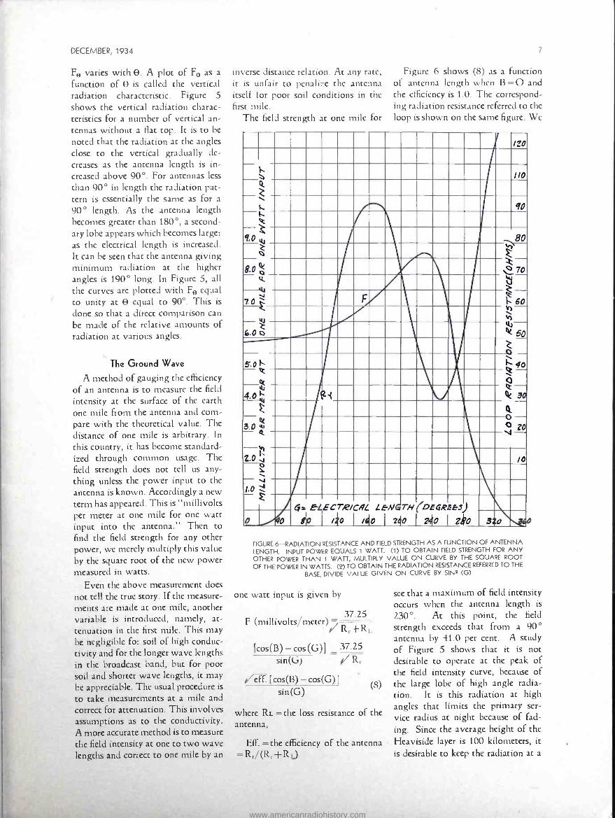
The field strength at one mile for
Figure 6 shows (8) as a function of antenna length when B =0 and the efficiency is 1.0. The correspond- ing radiation resistance referred to the loop is shown on the same figure. We
r 120
//0 Q.
V. 90
e - t 0 W .80
2 o F
8.0 ó 70 11 ú
7 F h 60
W h - 6.Oó
W 1k 50
Z o - 5.0Q Q 40 - .
Q 4_0 (2I 30
Z
3 .04
4 O
V20 -h 2.0 /O 0 a
60 £
db E ECT,F/CAL
/40 I mlo
LE-NGTH
I ?d0 I
( DEGREE3)
2t0 1 Zko 0 /40 3 o .,
FIGURE 6- RADIATION RESISTANCE AND FIELD STRENGTH AS A FUNCTION OF ANTENNA LENGTH. INPUT POWER EQUALS 1 WATT. (1) TO OBTAIN FIELD STRENGTH FOR ANY OTHER POWER THAN 1 WATT, MULTIPLY VALUE ON CURVE BY THE SQUARE ROOT
OF THE POWER IN WATTS. (4) TO OBTAIN THE RADIATION RESISTANCE REFERRED TO THE
BASE, DIVIDE VALUE GIVEN ON CURVE BY SIN2 (G)
one watt input is given by
37.25 F (millivolts/meter)
[cos(B) - cos (G)] 37.25
sin(G) Rr
[cos(B)-cos(G)] sin(G)
(8)
where RL the loss resistance of the antenna,
Eff. = the efficiency of the antenna = Rr /(Rr+RL)
see that a maximum of field intensity occurs when the antenna length is
230 °. At this point, the field
strength exceeds that from a 90° antenna by 41.0 per cent. A study of Figure 5 shows that it is not desirable to operate at the peak of the field intensity curve, because of the large lobe of high angle radia- tion. It is this radiation at high angles that limits the primary ser- vice radius at night because of fad- ing. Since the average height of the Heaviside layer is 100 kilometers, it is desirable to keep the radiation at a
www.americanradiohistory.com

8 BROADCAST NEWS
minimum for values of O lying between 0° and 30 °. It is obvious from Figure 5 that a 190° antenna does this best. It will be noted that the field strength along the horizon is only 27.0 per cent greater than that obtained with a 90° antenna. Hence the primary reason for using such an antenna is not to increase the signal strength along the ground but to increase the distance to the fading zone.
It is of interest to examine the field strength at one mile as given by (8) when a flat top or capacity area is used. This case also covers the
the peaks are higher than the value obtained with a straight vertical 230° antenna. It would appear at first glance that it is always desirable to load an antenna at the top. Actually there are only a few antennas which yield better results by thus loading. For instance, a study of the vertical radiation charac- teristics shows without exception that a large secondary sky lobe is present when the antennas are oper- ated with such a value of B that the field intensity is maximum. The radiation characteristic is similar to the one on Figure 5 labelled "G =
/0
40 o III 1 -I--,
ZO %1 A --, mil-i=iry/
R=60
A A
5 1 //./
.
/ I
20 B°
lo I Co 0 /a101 I o V4o /60 /8c
FIGURE 7 -FIELD INTENSITY AT ONE MILE FOR 1 -WATT INPUT TO A LOADED ANTENNA
tuned capacity area. Figure 7 shows the field strength at one mile for one watt input as a function of the load- ing at the top of the antenna for a number of antenna heights. We see that loading at the top increases the field strength in every case. Some of
2300." Of course, if we are inter- ested in getting the largest ground wave and not interested in control- ling the sky wave, it might be desirable to use an antenna 120° high with 100° of loading. It should be pointed out that, for any
height antenna, with the loading adjusted at the top to give a vertical radiation characteristic which re- duces the sky wave at the high angles as well as does a simple 190° antenna, the field strength at one mile for one watt input is very nearly 7.75 millivolts per meter. Another factor to be considered is radiation resistance. If the radiation resistance is extremely low, the efficiency of the antenna may be ruined by the loss in the loading coil alone. For instance, if the antenna is 90° high, the best suppression of sky wave occurs when B =125°. Figure 3 shows that the correspond- ing radiation resistance is about 1.5 ohms at the loop or about 4.5 ohms at the base of the antenna. At this point, 2.0 ohms in the loading coil will reduce the efficiency to less than 70.0 per cent. It is also seen that a straight 190° antenna can be re- placed satisfactorily by an antenna 150° high with about 50° loading at the top.
The Ground System
Since the ground system plays an important part in the performance of an antenna, some general recom- mendations will be made here. The ground system should consist of buried radial wires. Where the antenna is of the order of one half wave length long, the maximum earth loss occurs at about 0.35 wave lengths from the antenna. It is important to have the ground system extend well beyond this point. If only a few radial wires are used, the current returning to the base of the antenna through the ground will flow in the earth itself, instead of in the buried wires provided to carry it. An efficient antenna system should have at least 100 radial wires. With ordinary methods of laying these buried wires, that is, digging trenches 1.5 to 2 feet deep and refilling after the wire is rolled out, the cost of such a system would become pro- hibitive. However, it is not neces- sary to bury the wires more than 6 to 12 inches below the surface. For depths of this order, the wire can be laid using a special wire laying plow consisting essentially of a straight blade with a pipe welded on the back. The blade is pulled
www.americanradiohistory.com
DECEMBER, 1934
through the ground and the wire is
fed from a red through the pipe. If the soil is not especially hard or rocky, the complete ground system
can be laid in a kw days
Departures from the Simple Theory
The above considerations have
all been made on the assump-
tion that the current is sinusoidally distributed. We have made ex-
tensive tests on towers used as
antennas and have found that the
current distribution departs seriously
from the sinusoidal, due to the fact
that the cross -section of the tower varies along the tower. It is rather a
formidable task to measure this cur- rent distribution on an actual tower. We have, however, measured the
distribution on small models oper-
ated at high frequencies. The results of these tests, as well as
extensive measurements on actual
towers, will he given at a later date.
One of these tests was made on a
tower 0.597 wave lengths high.
Instead of having a current dis-
tribution as shown by the curve on
the extreme right of Figure 2, it was
found that the current along the
antenna showed no tendency to cross through zero to negative values.
The measured distribution was as
shown in Figure 8. These departures
from the sinusoidal make it extreme-
ly difficult for the antenna designer
to control the radiation from the
antenna. It has been found that it is
most desirable to use a tower which has a constant cross section electri-
cally over its entire length.
General Recommendations The type of antenna system to
erect will depend a great deal on the
type of service and class of channel.
For a cleared channel station with a
power of 50 kilowatts or more, fad-
ing will he the most serious limita- tion on the service arca. In this case,
it is desirable to use an antenna giv- ing minimum sky wave at the angles
most likely to produce fading. For
this situation, the best antenna is the
190° antenna or its equivalent. For
stations on regional channels, this sane antenna 111.1r he used if no
Interference from another station on
the same channel is encountered in
the zone which svill be freed from fading 1w the use of this antenna.
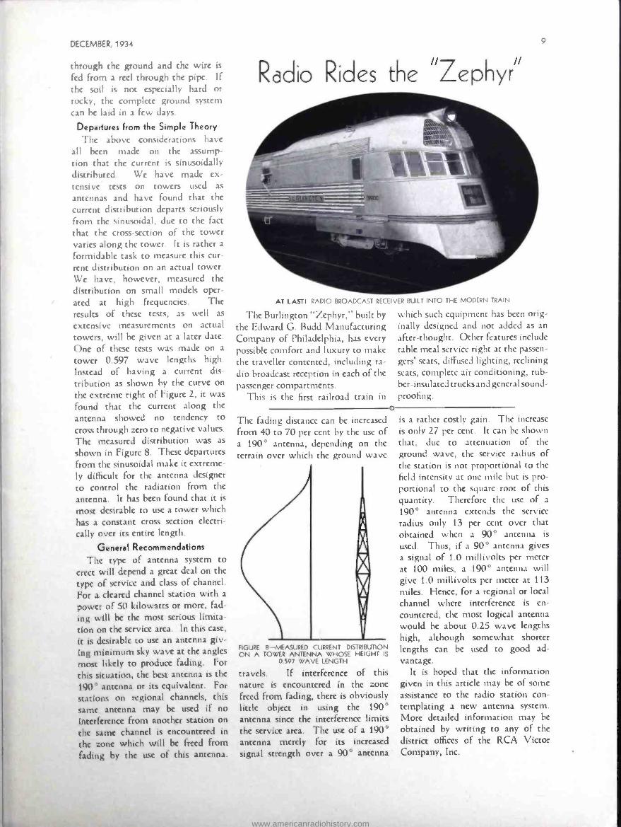
Radio Rides the "Zephyr"
AT LASTI RADIO BROADCAST RECEIVER BUILT INTO THE MODERN TRAIN
The Burlington "Zephyr," built by
the Edward G. Budd Manufacturing Company of Philadelphia, has every possible comfort and luxury to make the traveller contented, including ra-
dio broadcast reception in each of the
passenger compartments. This is the first railroad train in
The fading distance can be increased
from 40 to 70 per cent by the use of a 190° antenna, depending on the terrain over which the ground wave
o
FIGURE 8 -MEASURED CURRENT DISTRIBUTION ON A TOWER ANTENNA WHOSE HEIGHT IS
0.597 WAVE LENGTH
travels. If interference of this nature is encountered in the zone
freed from fading, there is obviously little object in using the 190° antenna since the interference limits the service area. The use of a 190° antenna merely for its increased
signal strength over a 90° antenna
9
which such equipment has been orig- inally designed and not added as an
after -thought. Other features include table meal service right at the passen-
gers' seats, diffused lighting, reclining seats, complete air conditioning, rub- ber- insulated trucks and general sound-
proofing.
is a rather costly gain. The increase
is only 27 per cent. It can be shown that, due to attenuation of the ground wave, the service radius of the station is not proportional to the
field intensity at one mile but is pro- portional to the square root of this quantity. Therefore the use of a
190° antenna extends the service radius only 13 per cent over that obtained when a 90° antenna is
used. Thus, if a 90° antenna gives a signal of 1.0 millivolts per meter at 100 miles, a 190 ° antenna will give 1.0 millivolts per meter at 113
miles. Hence, for a regional or local channel where interference is en-
countered, the most logical antenna would be about 0.25 wave lengths high, although somewhat shorter lengths can be used to good ad- vantage.
It is hoped that the information given in this article may be of some
assistance to the radio station con- templating a new antenna system. More detailed information may be
obtained by writing to any of the
district offices of the RCA Victor Company, Inc.
www.americanradiohistory.com

BROADCAST NEWS
The RCPT Rdcio Tube That Fell Out of the Stratosphere
A \D STILL WORKS!
A FRAGILE glass tube, which was picked up unscathed from a mass of unrecognizable
wreckage of the stratosphere balloon, perpetuates the memory of one of the most dramatic broadcasts in radio history.
It was one of the seven Radiotrons in the tiny 8 -watt, short -wave trans- mitter that enabled the world, sitting breathlessly by its radio, to listen to the voices of three men ten miles in the air fighting for their lives as their stratosphere balloon Explorer shot earthward as "fast as a man would fall if he jumped off a roof."
The tube, dropped with the equip- ment, survived the shock of the crash in a Nebraska cornfield, and remains in perfect working order, although the plate structure is slightly bent. This simple glass relic, reposing in the "radio museum" of the National Broadcasting Company in Radio City, represents not only a landmark in aeronautic history but in the his- tory of broadcasting.
It will recall to posterity the thrill- ing two -way conversation which a
BEFORE THE ASCENT
THE COMPACT LITTLE 8 -WATT TRANSMITTER THAT MADE HISTORY
AFTER THE CRASH FALLING OUT OF THE SKIES LIKE A METEOR, THIS MASS OF TWISTED WRECKAGE LANDED IN A NEBRASKA CORNFIELD. NOTE THE RCA RADIO TUBE STILL INTACT -
AND, AFTER TESTS, PROVEN STILL IN PERFECT OPERATING CONDITION
nation -wide radio audience heard from the time the great balloon took off near Rapid City, South Dakota, ripped open at an altitude of more than 60,000 feet, and continued until the last of three balloonists parachuted to safety, more than seven hours later.
When a 50 -foot gash suddenly halted the balloon's ascent at an alti- tude of 37,000 feet, Major William E. Kepner, commander, was heard to say :
"I don't know how long it will hold together, but there's nothing that we can do about it."
Then Captain Albert W. Stevens, observer, and Captain Orvil A. An- derson, two of the other occupants of the gondola, were heard discussing the grim details of the accident. "There's a big hole in the bottom ... she's go- ing back down again ... we're corn- ing down 400 feet a minute...."
www.americanradiohistory.com

DECEMBER, 1934 11
General Westover and others on the ground. From the War Department Building in Washington, the voices of these officials and others were flashed over NBC networks to short -wave transmitters, which in turn shot them out into the air to be picked up in the stratosphere, where they penetrated the air -tight metal ball in which the fliers were sealed.
Even if all the equipment on the balloon had been demolished and the fliers had perished, posterity, none the less, would have a complete record of their ascent and descent, thanks to the little transmitter.
It was the second time in the his- tory of wireless that the National Broadcasting Company had brought to world radio listeners exclusive broadcasts from the stratosphere. The first time was in November, 1933, when Settle and Fordney made an as- cent of 61,237 feet from Akron, Ohio.
PREPARING FOR ASCENT
MAJOR w. E. KEPNER (LEFT) AND CAPTAIN A. W. STEVENS, SHOWN INSIDE THEIR STRATO- SPHERE GONDOLA, TRYING OUT THE SPECIAL NBC TRANSMITTER AND RECEIVER WHICH KEPT
THEM IN CONSTANT TWO -WAY COMMUNI- CATION WITH THE GROUND DURING THEIR
TRIP TO THE STRATOSPHERE
The world listened breathlessly as one of the three airmen asked another :
"What's the highest you ever jumped without oxygen ?"
"About 24,000 feet," came the answer.
Even after the balloonists leaped one by one out of the falling gondola and parachuted safely to earth, the carrier wave of the radio transmitter remained on the air until the balloon itself crashed.
The twisted and battered radio equipment, which now occupies a
prominent place in the "radio mu- seum," enabled not only the listeners to get their information on the ascent first -hand from the three airmen them- selves, hut also made it possible for the intrepid trio to get the advice and encouragement of General Lejeune,
THE MOMENT THE GONDOLA HIT
1 IS THE STRATOSPHERE BALLOON AS IT CRASHED TO EARTH, 2 AND 3 ARE THE PARA- CHUTES OF TWO OF THE STRATOSPHERE EXPLORERS (THE THIRD FLIER'S PARACHUTE IS BEYOND RANGE OF THE CAMERA). NOTE THE SHREDS OF THE DISINTEGRATED BALLOON FLOATING IN MID -AIR DIRECTLY ABOVE THE CRASHED GONDOLA
www.americanradiohistory.com

BROADCAST NEWS
The Type OP -4 Portable Broadcast
Speech input Equipment By A. N. CURTISS, Radio Engineer, RCA Victor
l YOU were building a portable broadcast amplifier, what features
would you incorporate in its gen-
eral design? How much gain should
it have? Should it be adaptable to AC operation by the addition of the
proper power supply? These questions
and many others have been asked of competent operators who have had
considerable experience in remote
pick -up programs.
The result of this general question- naire and the general advance in tubes
and circuit design have been com- bined in a new RCA Victor Portable
Broadcast Amplifier, to be known as
the OP -4.
The general purpose of the ampli- fier is for remote pick -up of outside
programs such as football games,
outdoor concerts, political and social
meetings and all the other important affairs that may happen outside the
studio. It may also be used as a semi-
permanent installation from locations such as hotel ball rooms where dance
A. N. CURTISS, RCA VICTOR
programs are picked up regularly several times a week.
Because we are entering a period of high -quality pick -up and transmission, it is rather important that this ampli- fier be within this class. Telephone
lines are being improved; studio equipment and transmitters are al-
ready in the high -quality field, so it is
FIGURE 1- CHASSIS OF THE AMPLIFIER-CONTROL. UNIT (REAR VIEW)
necessary that an amplifier for remote pick -up be of the same high quality type as the rest of the station equip- ment. The OP -4 amplifier has a use-
ful frequency range from 40 to 12,000 cycles and is essentially flat from 60 to 8,000 cycles. Its volume range is
such that it will handle a Velocity Microphone, or the new Type 50 -A Inductor Microphone which has been
developed particularly for use with the OP -4 for outside pick -up work.
General Specifications
Two carrying cases enclose the
complete amplifier. The amplifier carrying case has a detachable cover, which may be removed by opening
the catches, two on each side. Fig-
ure 2 shows the front of the amplifier
after the cover has been removed.
The amplifier case has a copper shield,
which encloses the amplifier in a com-
plete electrostatic shield. The battery
supply is carried in a separate battery
box and contains an "A" battery of the lightweight aircraft type and four "45" -volt "B" batteries. Space is
also arranged in the battery box for
three Inductor Type Microphones
(50 -A), a set of spare tubes, three
microphone cables (30 feet each) and
one power cable (10 feet long). There
is also sufficient space to carry a small
amount of tools and a pair of head-
phones if so desired. The battery box and the carrying case for the amplifier are cases similar in size and approxi- mately 201 z inches long, 15 inches
high and 81 z inches deep.
These cases, when complete with equipment, weigh approximately 50
pounds each.
One radical departure has been
made in the design of this amplifier.
The conventional heavy wooden case
has been discarded, and a lighter
www.americanradiohistory.com

DECEMBER, 1934
FIGURE 2 -THE AMPLIFIER -CONTROL UNIT (FRONT VIEW)
wooden case lined inside and out with a heavy gray fiber is used. The change to this type of case was par- tially necessitated by the increased weight in the amplifier. Because of a
much higher gain, and low level mix- ing, it was necessary to shield and double shield vital parts of the circuit. The fiber construction was suggested and designed by a trunk company that has been building fiber trunks for department stores for years. Based on their experience in the rough handling of these trunks, it is felt that this new construction will easily prove itself in
the field. Another change is the departure
from the conventional black color for all panels. The cases are a battleship gray and the front panel of the am- plifier is finished with a new durable wrinkled gray finish. All the parcs behind the panel are finished in silver - gray opalescent.
Reducing weight of the amplifier presented a considerable problem in
this high -gain amplifier. The tube boxes are fabricated from sheet steel
for shielding, but all the other parts are made out of aluminum or duralumin.
Electrical Specifications
The amplifier has an overall gain from input to output, including mixers, of 92 db. The undistorted output level is plus 6 db. or 50 milliwatts.
The input is provided with three channels, using 250 -ohm balanced
H" pads for mixers in each channel. The output matches into a 500 - ohm line.
The OP -4 amplifier utilizes the latest types of Radiotrons to give better performance in gain and fre- quency response. The first stage uses
an RCA -77 as a tetrode and is re- sistance coupled to the second stage, another RCA -77 used as a tetrode. This second stage is also resistance coupled to the output stage which uses an RCA -41 as a triode. The master gain control is used in the grid circuit of the second stage. The output transformer feeds into a 500 - ohm line output plug through two key switches. There are two output plugs provided, regular and emer- gency. A key switch controls each output and a four db. pad may be
13
inserted in the line through this same key switch. A phone jack amply pro- tected against shorting the output lines is provided for monitoring.
A volume indicator meter is tied directly across the output and with its attenuator will handle levels from minus 10 db. to plus 8 db. The switch itself varies in 2 db. steps from minus 8 to plus 6 db. The in- dividual mixers as well as the master gain control will attenuate 38 db. in
2 db. steps. The mixers and the master volume control are mounted on a separate sub -panel which is held to the main panel by three thumb screws. By removing these screws the mixers and master control may be
easily removed, the cover taken off,
and the units serviced without any difficulty.
Other mechanical features which should be mentioned are the double rubber suspension used on the input stages so that all shock noises are eliminated. As may be seen from Figure 3, the amplifier and plug panel on the rear of the amplifier are one assembly. Referring back to the sec-
ond figure, it may be seen that the main panel is held in the carrying case by four thumb screws, one in
each corner. A handle on the front of the amplifier facilitates removal. When the four thumb screws are loosened, the amplifier and plug panel slides out on its feet. The tubes are
then readily accessible as well as the rest of the amplifier. All parts are
easily serviceable, which is an impor- (Continued on Page 29)
FIGURE 3 -REAR VIEW OF_THE AMPLIFIER -CONTROL UNIT, SHOWING CONVENIENT FLUSH OUTLET RECEPTACLES
www.americanradiohistory.com
14
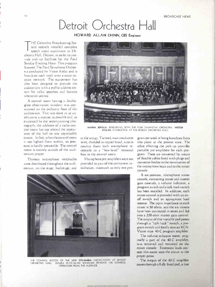
Detroit Orchestra Hall HOWARD ALLAN CHINN, CBS Engineer
THE Columbia Broadcasting Sys- tem recently installed complete speech input equipment in Or-
chestra Hall, Detroit, in order to pro- vide pick -up facilities for the Ford Sunday Evening Hour. This program features The Ford Symphony Orches- tra conducted by Victor Kolar and is
broadcast each week over a coast -to- coast network. The equipment has also been designed to provide the auditorium with a public -address sys- tem for talks, speeches and lectures whenever desired.
A control room having a double - glass observation window was con- structed on the orchestra floor of the auditorium. This was done in as un- obtrusive a manner as possible and, as evidenced by the accompanying pho- tograph, the addition of a radio con- trol room has not altered the appear- ance of the hall to any appreciable extent. In fact, when the control room is not lighted from within, its pres- ence is hardly noticeable. The control room is entirely outside of the audi- torium proper.
Thirteen microphone receptacles were distributed throughout the audi- torium, on the stage, backstage, and
BROADCAST NEWS
MARIA 1ERITZA, REHEARSING WITH THE FORD SYMPHONY ORCHESTRA, VICTOR KOLAR, CONDUCTOR, AT THE DETROIT ORCHESTRA HALL
in the wings. Twisted, two- conductor wire, shielded in copper braid, runs in conduit from each microphone re- ceptacle to a "low- level" terminal box in the control room.
Microphone pre- amplifiers were not provided as part of the permanent in- stallation, inasmuch as only one pro-
THE CONTROL BOOTH OF THE NEW COLUMBIA INSTALLATION AT DETROIT
ORCHESTRA HALL. DOUBLE PLATE-GLASS WINDOWS SEPARATE THE CONTROL OPERATORS FROM THE AUDIENCE
gram per week is being broadcast from this point at the present time. The office effecting the pick -up provides portable pre -amplifiers for each pro- gram. These are connected by means of flexible cables fitted with plugs and connector bodies to the termination of the microphone leads and to the mixer console.
A six -position, microphone mixer console, containing mixer and master gain controls, a volume indicator, a program switch and a talk -back switch has been installed. In addition, each mixer control is provided with an on- off switch and an appropriate load resistor. The input impedance to each mixer is 50 ohms, and the six mixers have been connected in series and fed into a 250 -ohm master gain control. The output of this variable pad passes through a "talk- back" switch, a pro- gram switch and finally into an RCA - Victor type 40 -C program amplifier.
The volume indicator meter, orig- inally a part of the 40 -C amplifier, was removed and mounted on the mixer console. Extension leads con- nect this meter into the circuit at the proper point.
The output of the 40 -C amplifier passes through a 6 db. fixed pad, a line
www.americanradiohistory.com

DECEMBER, 1934 15
SPEECH INPUT" EQUIPMENT
ORCHESTRA HALL --DETROIT
M /XER CONSOLE
PRE AMP rM
a
4.1
LOADAES/STÖR SOn
m
I
I
I
CONTROL C /?CU /T ONLY
TALK BACK E:1-x- C
25012
TB SW /N
--IV 200/200n
200n
switch, and then to the line connecting Orchestra Hall with the CBS network.
In addition to providing programs to the radio line, the 40 -C amplifier supplies two RCA -Victor type
/LOAD RES /S TOR -/S n
LOUD TO PA
SPEAKERS
tric /5n
- '
R MON /TOR SPAR
TALK BACK SPAR
TAGE PHONES
ti -I R F-
#/5n x 5óOñ PAge2
AA 4/948 PA #1
AA 4/948
CUE SW IN
PGA/ AMP 40-C
600
I 2 _---{ vc F-
2 C
SOO n
200/500 n
VC VOLUME CONTROL C- CO /L E - EQUALIZER SW- SW /TCH R -RELAY
ACK -.-- TW /S T LOCK
INTERIOR OF COLUMBIA'S NEW CONTROL ROOM AT DETROIT ORCHESTRA HALL --
RCA VICTOR EQUIPPED
CUE L /NE
UZI x 1
PGML LIE
AA- 4194 -B monitoring amplifiers. One of these units is used to energize two RCA -Victor type UZ-4209 loud- speakers, one of which is placed in the control room for monitoring purposes and the other mounted backstage for use in connection with the talk -back circuit. The output of this monitor amplifier also connects to a circuit leading to the stage, where it may be used to feed a pair of headphones for an auditor at this point.
The second monitor amplifier ener- gizes four RCA Photophone loud- speakers, having type MI -1425 speaker units, connected to type MI -477 horns. These loudspeakers, which are mounted behind valances in the upper boxes on each side of the stage, serve as a public- address system when it is desired to use the speech input equip- ment as such.
Provisions were made for the in- stallation of public- address loud- speakers in any one or all of three lo- cations in the auditorium. High -level audio and loudspeaker field supply outlets are provided in the upper boxes to the right and the left of the stage and over and back of the proscenium arch. The wiring from these outlets is brought in conduit to a "high- level" terminal box in the control room.
The "talk- back" equipment con- sists of a two -button carbon micro- phone in the control room, a suitable input transformer and a volume con- trol. This equipment is wired through a switch and an associated relay so that the occupants of the control room
(Continued on Page 32)
www.americanradiohistory.com

BROADCAST NEWS
LET'S GET ACQUAINTED
RCA VICTOR TRANSCRIPTIONS IN THE MAKING
A RECORDING SESSION IN THE WORLD -FAMOUS "CHURCH STUDIO" AT CAMDEN, N. J. THE CHARAC- TERS, LEFT TO RIGHT, ARE MATHILDE HARDING, PIANIST; FRANK CHASE, OF NBC PRODUCTION DEPART-
MENT, OSCAR J. CLAIR, PIPE ORGAN TECHNICIAN; CHARLES SOOY, RECORDING ENGINEER FOR RCA
VICTOR; AND IRENE HARDING, ORGANIST. THE UNUSUAL ORGAN -PIANO DUOS PRODUCED BY THE
HARDING SISTERS HAVE GAINED WIDESPREAD POPULARITY AMONG THE LISTENING PUBLIC. THE
VELOCITY MICROPHONE IS USED TO MAKE THESE HIGH FIDELITY RECORDINGS
KOA, NBC
ROBERT H. OWEN, engineer in
charge ofstation KOA at Denver, Colo., visited the NBC studios at
"Radio City," New York, during the week of October 14th, and was es-
corted on a tour through the "works" by Ray Guy, NBC Radio Facilities Engineer. Probably Ray Guy was trying to reciprocate for the ride over the mountain tops surrounding Den- ver during his visit out there in June and July.
NBC
William Duttera, NBC Radio En- gineer, is very busy on the directional antenna at Raleigh, S. C.
William Fitch, NBC Radio Engi- neer, has spent the last few months covering the middle West in one of the NBC engineering cars, giving the RCA Víctor 75 -B Measuring Set a
good workout. Lester Looney, NBC Radio Engi-
neer, has been dividing his time be-
tween Washington, D. C., and Cleve-
land, Ohio, during the past few months, making high fidelity adjust- ments on NBC transmitters.
WTIC
J. C. Randall, Plant Manager of WT1C, Hartford, Conn., having completed an extensive program of studio facilities expansion which was started early in June, is off on a hard earned vacation in the Adirondack Mountains to do a little deer hunting. Let's hope the boys at WTIC will enjoy the venison.
WBEN, WHEC, WGR
Other broadcast engineers seem to have taken advantage of the hunting season for their vacations. Among these are R. J. Kingsley of WBEN, M. H. Clarke of WHEC, and Karl B. Hoffman of WGR.
WLVA
Station WLVA of Lynchburg, Virginia, suffered a major catastrophe on November 8th, when fire de-
stroyed their Main Street studios.
Due to the quick wit and ingenuity of A. E. Heiser, Station Engineer, programs were fed to the transmitter from remote points, thus avoiding loss of time on the air.
WHBF
Station WHBF, Rock Island, Illi- nois, has purchased a new RCA Vic- tor 250 -W transmitter for opera- tion at 100 watts.
WCFL
Station WCFL of the Chicago Federation of Labor, which for several years has been operating at 1500 watts with an RCA Type 1 -B transmitter and speech input equipment, is replac- ing this installation with one of the new RCA Víctor Type 5 -C all AC operated 5 KW sets, at their new site near Downers Grove, Illinois. Con- struction work on their new building is progressing rapidly and the new station will probably be on the air shortly after January 1, 1935. This new installation boasts a 530 -foot half -wave vertical radiator.
www.americanradiohistory.com

DECEMBER, 1934
BROADCASTI \G PERSO \ALITIES
WDOD
Joe Eiselein, chief engineer of WDOD in Chattanooga which is
owned by Earl Winger and Norman Thomas, claims that his new half wave vertical radiator has practically doubled his signal at one mile. This improvement was accomplished merely by changing from their old antenna system to the new. Doubling the signal intensity at one mile is
equivalent to quadrupling the power of the transmitter.
WMAZ
E. K. Cargill and George Rankin, manager and engineer respectively of WMAZ in Macon, Ga., are devoting most of their time at present to the installation of their new 1000 -watt transmitter and 3/8 wave vertical radiator. It is expected that the sta- tion will be in operation shortly after the first of the year.
WDAE
L. S. Mitchell, manager of WDAE in Tampa, is quite technical minded and is probably one of the few radio station managers in the country who is willing to stay up nights helping his engineer making adjustments and changes in the transmitter. William Pharr Moore, engineer of that station, is responsible for all the technical operations.
WIOD
Radio Station WIOD has already started construction of their new studios in the News Tower on Bis-
cayne Boulevard in Miami. The studios will be housed in a new section being added to the roof of the fourth floor of the building directly behind the tower. RCA Victor studio equipment including the new Induc- tor Microphone will be used in the studios. The owners have spared no expense in working out what is con- sidered to be the last word in
studio design.
Jesse H. Jay, manager of Station WIOD, is busily engaged in working out details for the opening of their new studios in the News Building. It is expected that the studios will be
17
J. E. ADAMS, CHIEF CONTROL OPERATOR AT WFBC, IN THE CONTROL ROOM WHICH NOW INCLUDES AN RCA VICTOR 41 -B PREAMPLIFIER, A NEW 4- CHANNEL MIXER, AND
A VELOCITY MICROPHONE
dedicated during the early part of January when a nation -wide hook -up of the NBC will be fed from Miami.
Milton C. Scott, chief engineer of Station WIOD, is using a new RCA Victor type OP -4 outside pickup amplifier for temporary studio equip- ment while his present studio equip- ment is being combined with new equipment and moved to this station's new studios.
The International Radio Club will hold its annual meeting in Miami on January 7, 8, and 9. Headquarters will be at the Miami Biltmore Hotel. Elaborate plans have been made and it is expected that the party will be
the greatest affair that has ever been
known to radio broadcasting. The dedication of WIOD's new studios will constitute part of the program.
WMBR Frank King, manager of WMBR
in Jacksonville, Florida, has done an excellent job in building up the popularity of that station since it was moved from Tampa. Mr. King is
planning big things for his new station, but won't tell us all about them just yet.
WDBO
Colonel George Johnson, owner of WDBO in Orlando, Florida, is quite proud of his composite radio station which has just been increased to one kilowatt. The entire station including studios and transmitter is very well appointed, having been entirely de- signed and constructed by his chief engineer, Mr. J. E. Yarbrough.
KWCR
Station KWCR at Cedar Rapids, Iowa, has installed one of the new RCA Victor Type 1 -D transmitters, putting this station in a class by itself west of the Mississippi River, with "High Fidelity" performance.
WOC
A new RCA Victor ET -4250 trans- mitter (250 watts) and speech input equipment have been purchased for
the new WOC station at Davenport, Iowa.
www.americanradiohistory.com

BROADCAST NEWS
WTAR Goes H Fidelity By J. L. GRETHER, Technical Director and Chief Engineer, WTAR
JULIUS L. GRETHER, TECHNICAL DIRECTOR AND CHIEF ENGINEER, WTAR. ORDINARILY PRETTY EASY TO GET ALONG WITH, BUT THEY CALLED HIM OUT OF BED TO TAKE THIS PICTURE, JUST AFTER A 36 -HOUR STRETCH INSTALLING
NEW EQUIPMENT
STARTING out early in 1923 as amateur station 3GY, with an outfit built up by some of the
radio -inclined members of the staff of the Reliance Electric Company, then the largest and most thriving electrical contractors and dealers in
the Virginia Tidewater, there gradu- ally came into being Virginia's pioneer broadcasting station WTAR. The first regular program was put on the air on September 21, 1923, using a composite 15 -watt transmitter, equipped with the almost -forgotten UV-202 power Radiotrons, and sin- gle- button carbon microphones. The station achieved immediate popular- ity, however, and in less than two months was forced to increase its power to 100 watts, by insistent public demand for stronger signals. Another composite transmitter con- sisting of two UV -203 -A oscillator tubes, modulated by two more UV- 203-A's, and fed by the well -known 7 -A amplifier, was placed in opera- tion early in December of 1923. Since the owners of the station were the leading battery dealers for Nor- folk, this transmitter was empowered by storage batteries, both for filament and plate. The 1000 -volt bank of "B" batteries was the main item of interest in the transmitter power room, and the bane of existence to the oper- ators, who had to keep them serviced!
Under the leadership of Jack Light, station manager, WTAR rapidly progressed in spite of the vicissitudes
STUDIO A (20 BY 36 FEET), LOOKING TOWARD CONTROL ROOM. RADIO STATION WTAR, NORFOLK, VA.
JOHN C. PEFFER, ASSISTANT CHIEF ENGINEER, WTAR- A 6 -FOOT HUSKY, IN A SERIOUS MOOD
of early - day broadcasting, and in 1926 installed its first master- oscillator power -amplifier transmitter, using 500 watts, with two UV -204 -A amplifiers and two UV -204 -A mod- ulators. When the demand for higher percentages of modulation began to be felt in the early days of the Federal Radio Commission, the modulator was modified to use two UV- 851's, and a 50 -watt speech amplifier was added to drive the grids. This per- mitted about 55 per cent modulation and materially increased the range of the station. This transmitter remained in use, with minor changes and im- provements, until the necessity arose for maintaining the carrier frequency within plus or minus 50 cycles, whereupon plans were begun for an entire new station.
New Site The new transmitter site was
chosen in the fall of 1930, some five miles out in the country from the thickly populated city area, and work began immediately on the construc- tion of a suitable building and the two 150 -foot steel towers. A crystal - control transmitter, using low -level modulation and a water- cooled linear
www.americanradiohistory.com
DECEMBER, 1934
"Class B" R. F. amplifier, with ca- pacity coupling to the antenna for harmonic reduction, was installed. New speech input equipment was built by the engineering staff and was all completed before the arrival of the transmitter. During one of the coldest and nastiest spells of the winter of 1930 -'31 a six -wire cage antenna with six - wire cage lead - in was built, and it was while this part of the job was going on that the entire staff learned all about polar exploring. It was necessary to keep two blow torches going all the time to solder the joints, one inside the building and one outside. When the torch in use got too cold to vaporize the gas, it was exchanged for the hot torch inside, and the work went on.
The first crystal -controlled trans- mitter was officially dedicated on May 30, 1931, operating with 500
19
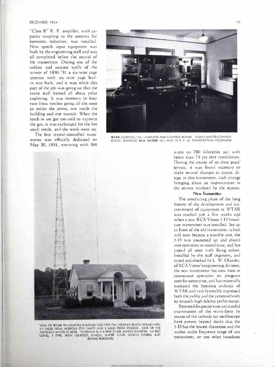
WTAR, NORFOLK, VA.- AMPLIFIER AND CONTROL BOARD. STUDIO MASTER CONTROL ROOM, SHOWING RCA VICTOR 33,, AND 78 R. P. M. TRANSCRIPTION EQUIPMENT
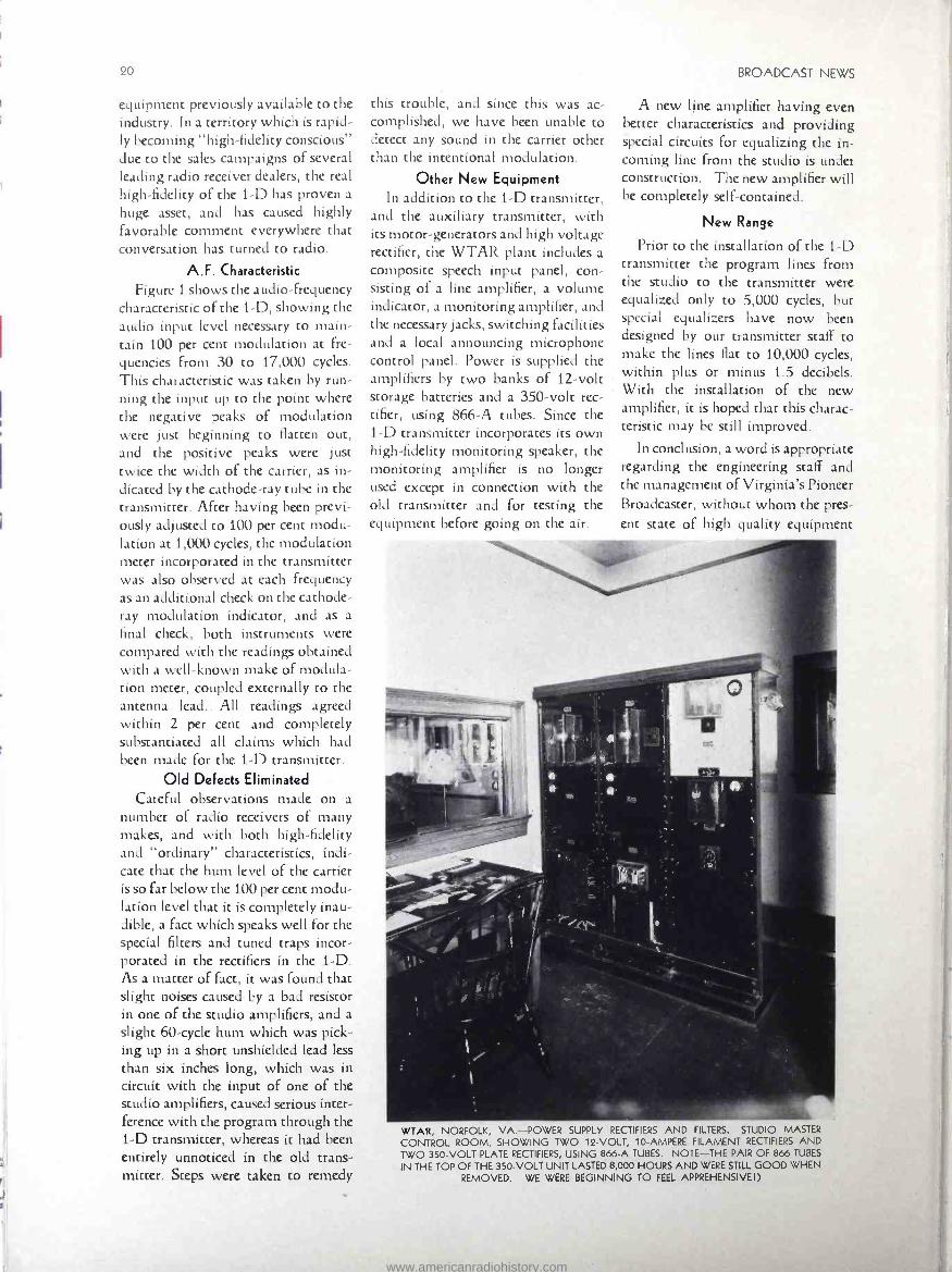
VIEW OF WTAR TRANSMITTER BUILDING, LOCATED ON VIRGINIA BEACH BOULEVARD,
1.7 MILES FROM NORFOLK CITY LIMITS AND S MILES FROM STUDIOS. ONE OF THE
ANTENNA MASTS IN REAR. ANTENNA IS A 6 -WIRE CAGE, 8 -INCH DIAMETER. 140 FEET
LONG, T TYPE, WITH 134 -FOOT, 2 -INCH, 6 -WIRE CAGE LEAD -IN (VISIBLE JUST
BEHIND BUILDING)
watts on 780 kilocycles and with better than 75 per cent modulation. During the course of its three years' service, it was found necessary co
make several changes in circuit de- sign in this transmitter, each change bringing about an improvement in the service rendered by the station.
New Transmitter
The concluding phase of the long history of the development and im- provement of equipment at WTAR was reached just a few weeks ago when a new RCA Victor 1 -D broad- cast transmitter was installed. Set up in front of the old transmitter, which will now become a standby unit, the 1 -D was connected up and placed into operation in record time, and has passed all tests with flying colors. Installed by the staff engineers, and tuned and checked by L. W. Olander, of RCA Victor's engineering division, the new transmitter has now been in continuous operation on program tests for some time, and has materially increased the listening audience of WTAR and very favorably impressed both the public and the personnel with its smooth high -fidelity performance.
Repeated frequency runs and careful examination of the wave -form by means of the cathode ray oscilloscope have proven beyond doubt that the 1 -D has the lowest distortion and the widest audio frequency range of any transmitter, or any other broadcast
www.americanradiohistory.com
20 BROADCAST NEWS
equipment previously available to the industry. In a territory which is rapid- ly becoming "high- fidelity conscious" due to the sales campaigns of several leading radio receiver dealers, the real high -fidelity of the 1 -D has proven a
huge asset, and has caused highly favorable comment everywhere that conversation has turned to radio.
A.F. Characteristic Figure 1 shows the audio- frequency
characteristic of the 1 -D, showing the audio input level necessary to main- tain 100 per cent modulation at fre- quencies from 30 to 17,000 cycles.
This characteristic was taken by run- ning the input up to the point where the negative peaks of modulation were just beginning to flatten out, and the positive peaks were just twice the width of the carrier, as in- dicated by the cathode -ray rube in the transmitter. After having been previ- ously adjusted to 100 per cent modu- lation at 1,000 cycles, the modulation meter incorporated in the transmitter was also observed at each frequency as an additional check on the cathode - ray modulation indicator, and as a
final check, both instruments were compared with the readings obtained with a well -known make of modula- tion meter, coupled externally to the antenna lead. All readings agreed within 2 per cent and completely substantiated all claims which had been made for the 1 -D transmitter.
Old Defects Eliminated Careful observations made on a
number of radio receivers of many makes, and with both high -fidelity and "ordinary" characteristics, indi- cate that the hum level of the carrier is so far below the 100 per cent modu- lation level that it is completely inau- dible, a fact which speaks well for the special filters and tuned traps incor- porated in the rectifiers in the 1 -D. As a matter of fact, it was found that slight noises caused by a bad resistor in one of the studio amplifiers, and a
slight 60 -cycle hum which was pick- ing up in a short unshielded lead less than six inches long, which was in circuit with the input of one of the studio amplifiers, caused serious inter- ference with the program through the 1 -D transmitter, whereas it had been entirely unnoticed in the old trans- mitter. Steps were taken to remedy
this trouble, and since this was ac- complished, we have been unable to detect any sound in the carrier other chan the intentional modulation.
Other New Equipment In addition to the 1 -D transmitter,
and the auxiliary transmitter, with its motor- generators and high voltage rectifier, the WTAR plant includes a
composite speech input panel, con- sisting of a line amplifier, a volume indicator, a monitoring amplifier, and the necessary jacks, switching facilities and a local announcing microphone control panel. Power is supplied the amplifiers by two banks of 12 -volt storage batteries and a 350 -volt rec- tifier, using 866 -A tubes. Since the 1 -D transmitter incorporates its own high- fidelity monitoring speaker, the monitoring amplifier is no longer used except in connection with the old transmitter and for testing the equipment before going on the air.
A new line amplifier having even better characteristics and providing special circuits for equalizing the in- coming line from the studio is under construction. The new amplifier will be completely self- contained.
New Range
Prior to the installation of the 1 -D transmitter the program lines from the studio to the transmitter were equalized only to 5,000 cycles, but special equalizers have now been designed by our transmitter staff to make the lines flat to 10,000 cycles, within plus or minus 1.5 decibels. With the installation of the new amplifier, it is hoped that this charac- teristic may be still improved.
In conclusion, a word is appropriate regarding the engineering staff and the management of Virginia's Pioneer Broadcaster, without whom the pres- ent state of high quality equipment
-
WTAR, NORFOLK, VA. -POWER SUPPLY RECTIFIERS AND FILTERS. STUDIO MASTER
CONTROL ROOM, SHOWING TWO 12 -VOLT, 10- AMPERE FILAMENT RECTIFIERS AND TWO 350 -VOLT PLATE RECTIFIERS, USING 866.A TUBES. NOTE -THE PAIR OF 866 TUBES
IN THE TOP OF THE 350 -VOLT UNIT LASTED 8,000 HOURS AND WERE STILL GOOD WHEN
REMOVED. WE WERE BEGINNING TO FEEL APPREHENSIVE I)
www.americanradiohistory.com

DECEMBER, 1934
THE NEW RCA VICTOR TYPE 1 -D TRANSMITTER WHICH PUTS WTAR IN THE "HIGH FIDELITY" CLASS
would never have been possible. The station is owned by Norfolk News- papers, Inc., the directors of which appointed Campbell Arnoux, former manager of KTHS, in Hot Springs National Park, as general manager of the station early in 1934. He suc-
ceeded Jack Light, who had carried the station through its early career to become a leading 500 -watt broad- caster, and who then became assistant manager, in charge of studio opera- tions. Himself a pioneer in the broad-
casting held, having brought two high -power stations out of the woods to become leaders in their territory, Mr. Arnoux proved himself a friend
indeed to the engineering department, demanding better performance and setting higher standards of operation. Not only were the standards set, but the equipment to achieve them was
made available. This has been of the greatest value in providing an incen-
tive to the entire engineering staff to make every improvement possible,
and, once made, to keep all equipment
operating at the peak of perfection.
+2
Ó O
_
ñ 9
21
Much credit is due those members of the engineering staff whose tireless efforts have made the achievement of these plans possible and without whose assistance the writer would have been severely handicapped in the completion of the many items of special equipment. Headed by John C. Peffer, assistant chief engineer, the staff is composed of Robert L. Ken- nedy, and William L. Davis, senior and junior plant engineers, respec- tively, and Myrle M. Harrison, con- trol operator in charge of studio production; Trafton Robertson, an- nouncer and control operator, and Gordon R. Kerr, announcer in charge of commercial continuity department.
In addition to the above, the com- mercial department boasts a large staff of salesmen, continuity writers, program arrangers and stenographers.
New Standards With the incentive which the ex-
cellent frequency characteristics of the 1 -D transmitter are bound to give the engineering department of any sta- tion, the broadcasting art as a whole will greatly benefit, for audio equip- ment must be brought up to the standard set by the 1 -D, and when this has been done and every station has become "high- fidelity" through- out, the manufacturers of all receivers will be forced to come through with real wide -range equipment, capable of ten -thousand -cycle reproduction. Then true and natural transmission, reception and reproduction of high - grade programs will be a reality to the vast listening public. The rapid strides which radio broadcasting has made in the past will then be as nothing compared to the pace possi- ble in its new seven -league boots.
]o too
1-i di
FIGURE 1 -AUDIO FREQUENCY CHARACTERISTICS OF RCA VICTOR TYPE 1 -D TRANSMITTER
AT WTAR, NORFOLK, VIRGINIA, OCTOBER 15th, 1934
FRGgIfCMÇY iu.. C,CCL$..
www.americanradiohistory.com

22 BROADCAST NEWS
Dic
TFIAT all the power plants in the world have not yet produced the equivalent of one -millionth of a
gallon of electricity? A million kilo- watt hours, used at 110 volts, represents less than 1- 15,000 of a grain. (Everyday Science and Me- chanics. )
That the RCA Victor Company has just produced an A. C. operated Amateur Communication Receiver, Model ACR -136 -a 7 -tube Super- heterodyne, with 460 K. C. inter- mediate frequency and a range of 540 to 18,000 K. C., continuous in three bands? The bands are changed by a switch on the front panel, and a full electro- dynamic loudspeaker is a
built -in feature, although 'phones may be plugged in.
Dinner in the Clouds
That on the sixty -fourth floor of the 70 -story RCA Building in Radio City, New York, there is a restaurant where 25 waiters and 25 cooks and helpers serve about 700 persons daily?
That there is an unsolved mystery in the transmission of sound made by
meteors? The fact that it is heard the instant the meteor is seen forces the conclusion that the sound is trans- mitted in some way other than air waves, for ordinary sound waves would take several minutes to travel the distance. (Popular Science.)
That with the addition of Chicago there are now six large cities in the RCA domestic radio -telegraph service with three more soon to be added? The cities are New York, Chicago, San Francisco, Boston, New Orleans and Washington. Those next to be
added are Los Angeles, Detroit and Seattle.
That RCA Radio Tubes respond to a million impulses a second, whereas a stopwatch, generally thought to be
the ultimate in precision and accuracy, functions only on tenth -of -a- second intervals?
you know? By W. S. FITZPATRICK, RCA Institutes
W. S. FITZPATRICK, THE "RADIO RIPLEY"
That a short story containing every known sound in the English language was read by a New Yorker, a Cali- fornian, a Bostonian, a Texan, a
Georgian, an Englishman and a
Frenchman, in a unique NBC -WEAF network broadcast?
Modern Magic That the accomplishment of RCA
Victor in producing a new Victor record of Caruso, re- recording the voice of that famous singer with the modern "fidelity" method and elim- inating the "tinny" accompaniment of the original recording, caused a reader to ask Science and Mechanics how it was done? In giving the pro- cedure the editor's reply stated that it was as much a musical feat as an electrical one.
That, excluding the photo- electric cell, there are some 300 uses for the three or more element vacuum tube for other than communication pur- poses, according to J. Kenneth Whit - teker, Chief Instructor at the New York school of RCA Institutes, who is preparing a book on the subject? Recognizing radio reception and transmission as "communication," and further eliminating the 250 or so applications of the photo cell, Mr. Whitteker's 300 other uses are being looked forward to with interest.
That an NBC release dated Oc- tober 31 gave thumb -nail sketches of 28 announcers of the New York NBC studios? It is noted that two of the recent additions attained their places without prior experience, one is a former NBC page, three studied law, three theology and two medi- cine. Three are former newspaper writers. Two are actors, six are singers and six are musicians. Three are listed as bachelors. (A condition or just another profession ?) Ed.
Pictures by Radio
That messages, maps and pictures transmitted by radio are reproduced on paper at the rate of a full letter - sized sheet every eight minutes, by an improved fac- simile receiver per- fected by RCA Victor engineers?
That the Kennelly -Heaviside layer, as the electrified region has been called for years, is now more often referred to as the Ionosphere? (Radio World.)
That an important recent develop- ment is the RCA emergency marine transmitter which operates from a
12 -volt battery, obviating the neces- sity of the elaborate 60 -cell storage battery equipment, with great saving in space and less maintenance at- tention?
That a new Department of Com- merce book gives an official list de- tailing frequencies, power and call letters of all short -wave stations throughout the world?
That a radio receiver has been
developed that picks up enough energy to turn a small motor at high speed?
That the biggest stars in radio are heard on the sparkling new NBC pro- gram, "Radio City Party," Saturday night, 9 to 9.30 E. S. T.? Crossley statistics give this program a rating of 14.2, which means that it ranks among the first twenty leaders on the air -most of which are old- estab- lished programs.
www.americanradiohistory.com
DECEMBER, 1934 23
That because of the tall RCA structure, it and other buildings, as well as persons, in Radio City and the surrounding area in New York City, are protected from lightning? Its high steel frame and plumbing system make the building the best possible safeguard against lightning because the energy of the bolt is di- vided and subdivided by it.
That NBC radio pack transmitters have become standard equipment at the annual National Horse Show? This year's show at New York in November is the second at which spectators learn official results im- mediately through a transmitter car- ried by an NBC observer in the arena. Heretofore announcements were not made until long after the contestants left the ring.
Small But Efficient
That the RCA Victor Lapel Velocity Microphone has a frequency range extending from 80 to 7000 cycles with an output level the same as a standard Velocity microphone at four feet?
That 3,000,000 old radio tubes per year were sold as new until RCA de- veloped the non -refillable sealed car- ton to put the racketeer "on the spot "?
That the new RCA Victor 16 mm. Sound Movie Camera is only as big as a derby hat, can be used for "news reel" type of shots, where the camera- man describes the action directly into the built -in "mike," or with an ex- tension microphone for "on- stage" sound? Portable RCA Victor Sound Movie 16 mm. projectors are also available so that you can show these films or "rental" subjects right in your own home.
That United States has 43 per cent of the world's radio sets? Statistics just compiled by the Department of Commerce gives the radio census of the United States as 18,500,000 sets
as compared to a world total of 42,540,239. Europe has 18,594,605. (Scientific American.)
That the seven means of trans- mitting signals at sea are : radio,
Hags, semaphore, lights, rockets, whistles and bells?
World -Wide Wireless
That a new map of the world showing the R.C.A. Communications network of radio- telegraph and radio telephone systems, just compiled for distribution, is of scientific interest in noting how the circuits spread from New York and San Francisco to all parts of the world?
That government experts find the distance between Washington and California has increased by forty feet since 1926, when the last check was made?
Short Waves in Surgery
That Marconi in an article about the use of short radio waves in surgical operations states three great advantages in that the loss of blood is reduced, which leaves the surgeon a clear field, and the method reduces the shock to the patient's nervous system, greatly enhancing the pros- pects of rapid recovery unattended by the dangers of relapse?
That portable radio telephone sending and receiving sets, weighing 16 pounds, complete with batteries and antenna, are used in fighting fires by the U. S. Forest Service? Radio has proved extremely valuable for rapid communication during out- breaks of fire. (kadio World.)
That photo -electric cells play an important part in the operation of the world's largest underwater ve- hicle tunnel in England? The tunnel, incidentally, is a half mile longer than New York's Holland Tunnel. (Mod- ern Mechanix.)
World -Wide Program
That radio broadcasting scored another point when, with the use of a self -constructed radio receiving set, run by an old auto dynamo driven with a wooden wheel propelled by
human power, 300 miles from the nearest habitation, a man in Mpweto, Belgian Congo, Africa, listened to an NBC broadcast and gave to officials of that isolated place the news of their King's death, ten days before it reached there officially?
That the use of cellophane for coin wrappers enables the money to be counted without unwrapping the rolls?
That an Australian radio amateur named Pollock has established 2 -way voice communication with other amateurs in each of the six continents of the world, using a power of less than ten watts? (kadio World.)
That a contract for installation of short -wave radio -telegraph equipment on thirteen Standard Fruit and Steam- ship Company vessels has been receiv- ed by the Radiomarine Corporation of America? This will provide direct and constant communication between the ships and their home -office ports, even over distances of several thou- sand miles.
That, according to Popular Sci- ence, the language most intelligible over the telephone is Italian and the one conveying the most ideas in the shortest time is French?
Even the Orchestra
That for each act in the perform- ance at the Radio City Music Hall in New York, members of the orchestra change into uniforms fitting the setting or spirit of the act?
That at the Brooklyn Navy Yard there is a switching engine run by stored steam? The engine is charged with a 200 -pound pressure of steam from a stationary plant. It operates without loss of pulling power until the pressure falls below 50 pounds, which does not occur for several hours.
That the average span of life has increased from 20 years, in Queen Elizabeth's time, to the present 58 years for men and 61 for women?
That to make an artificial lake the size of Lake Erie all the power of Niagara Falls would be needed for years and all the pumps now in the United States would work for a life- time on the project? (Science and Mechanics.)
That nearing completion in one of the big NBC studios in Radio City, is an unusual pipe organ with three keyboards of 61 notes each, 20 pedals magnetically operating 1034 pipes, and 400 wires to hook up the stops in scores of combinations, which will produce an almost unlimited variety of effects and which will be heard over the air at an early date?
www.americanradiohistory.com

BROADCAST NEWS
Recent Police Radio Installations
THE transmitter of the new Police
Radio installation at Norfolk, Va., is located in the penthouse
on top of the National Bank of Com- merce building. The control point is
the First Precinct Headquarters build- ing at Cove and Court Streets. The control room has been specially pre-
pared for dispatching, in being iso-
lated with Cellatex on the walls and ceiling, and rubber tile on the floor.
The radio dispatcher's desk and files
are kept in this room, and the room has direct telephone connection with the police PBX board.
The transmitter is an RCA Victor type ET -5004. Ten AR- 5006 -A car receivers were installed, one in the car
By C. T. ANSON, RCA Victor Engineer
POLICE CHIEF H. W. CHURN, OF SUFFOLK, VA.
of Col. Charles B. Borland (Chief), three in cruisers at large, and six in scout cars assigned to the six districts
SLPiLMHLR 1>ì:
- 1
4 5 6 7
In 11 12 13 14 IS
18 19 20 2122 14 ': 26 27 28 29
CAPTAIN F. KEENAN, OF THE ROSELLE, N. J., POLICE DEPARTMENT AT THE MICRO-
PHONE OF THE RCA VICTOR POLICE RADIO TRANSMITTER
into which the city is divided. In ad- dition to the car receivers, six station - house receivers, AR -5024, have been installed -one at each of the sergeants' desks in the first, second, third, fourth and sixth precincts, and one in fire -
alarm headquarters.
The total coverage required at Norfolk was thirty -seven square miles, in an oblong shape, with the trans- mitter located at one end. The trans- mitting antenna is 220 feet above the street and, in several tests, coverage in excess of fifteen miles has been ob- tained. In addition to the three time - test calls per hour put out, the calls per day average between 60 and 100 - the higher figure being reached during week -ends.
Fifteen officers of the force success- fully paged their examinations for third -class radio telephone operators' licenses. Of these fifteen, three have been definitely assigned to dispatching duty. In addition to the officers, there are four men of the Bureau of Elec- trical Affairs, of which William Walsh is the Superintendent, who passed their examinations for licenses, and these four men are charged with the maintenance of the equipment.
The transmitter operates on 33.1 megacycles. The equipment went into operation officially September 16th, at 7 A. M., and in addition to the 72 time calls, 75 calls were handled by
the cars in the first twenty -four hours of operation. It is understood that the radio- equipped cars are now han- dling better than 75 per cent of the work previously handled by the pa- trol wagons, and, of course, doing it much faster.
Police Installation at Suffolk, Va.
The antenna is suspended from a
cypress pole mounted on the rear of the City Hall building, and guyed
near the top. The whole structure is
117 feet above ground. With this an-
tenna, commercially usable signals are obtained in an eight -mile radius. The RCA Víctor type ET -5004 trans- mitter is located near the sergeant's
www.americanradiohistory.com

DECEMBER, 1934 25
"TERRA-WAVE" ANTENNA MAST INSTALLED AT SUFFOLK, VA.
desk, with an operator's control box on the same table. As at Norfolk, the room in which the transmitter and control box are located was specially prepared for dispatching purposes -in other words, s3und- proofed.
The transmitter operates on 37.1 megacycles. Two type AR- 5006 -A car receivers were installed -one in
the Buick car of Chief H. W. Churn, and the other in a Ford touring car.
Suffolk is a city of 17,000 people. The radius of the city is approximately one and three -quarters miles.
Five men, including the chief, suc- cessfully took the examination for third -class radio telephone operators' licenses.
"Terra- Wave" Successful in
Danville, Virginia
Since early in 1934 the Police Radio Station W3XZ, located in Danville, Virginia, has been rendering an excel- lent account of itself. This RCA Victor installation is operated on a
frequency of 33,100 KC and it has the distinction of being the first police radio installation in the state of Virginia.
During the brief period it has already been in operation, this instal- lation has performed many useful tasks, including saving life, prevent- ing crime, and apprehending crimi- nals and fugitives from justice. Members of the Police Department in Danville praise the equipment very highly and feel that it has already proven indispensable.
Roselle, New Jersey, Police Praise
RCA Victor Equipment
Chief of Police B. M. Avery, of Roselle, N. J., states that while his officers and men deserve just praise for the excellent results they have been achieving lately in suppressing crime and bringing criminals to justice, he is highly appreciative of the RCA equipment, the installation of which marked a new chapter in the police routine in Roselle.
The police radio equipment at Roselle consists of an RCA Victor "Terra- Wave" transmitter, Type ET -5004, and four police receivers in automobiles. Captain F. Keenan is in
charge of the transmitting station at police headquarters.
Other New Installations
Other recent installations of RCA Victor "Terra- Wave" equipment in-
clude New City, New York, for the Rockland County Police, Scarsdale,
New York, and Clairton, Pennsyl- vania.
CHIEF OF POLICE B. M. AVERY, OF ROSELLE, N. J. (STANDING), AND OFFICER WILLIAM WOODRUFF SEATED IN AN RCA VICTOR RADIO -EQUIPPED POLICE CAR)
www.americanradiohistory.com
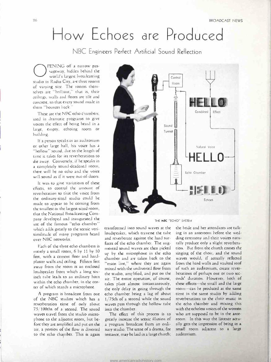
I low Echoes are Proc BROADCAST NEWS
uced NBC Engineers Perfect ArtiFicial Sound Reflection
OPENING off a narrow pas- sageway, hidden behind the world's largest broadcasting
studio in Radio City, are three rooms of varying size. The rooms them- selves are "brilliant," that is, their ceilings, walls and floors are tile and concrete, so that every sound made in
them "bounces back."
These are the NBC echo chambers, used in dramatic programs to give voices the effect of being heard in a
large, empty, echoing room or building.
If a person speaks in an auditorium or other large hall, his voice has a
"hollow" sound, due to the length of time ít takes for its reverberations to die away. Conversely, if he speaks in
a completely sound -deadened room, there will be no echo and the voice will sound as if it were out -of- doors.
It was to give variations of these effects, to control the amount of reverberation so that the voice from the ordinary -sized studio could be
made to appear to be coming from the smallest or the largest -sized room, that the National Broadcasting Com- pany developed and inaugurated the use of the famous "echo chamber" which adds greatly to the scenic veri- similitude of many programs heard over NBC networks.
Each of the three echo chambers is
merely a small room, 6 by 11 by 10
feet, with a cement floor and hard - plaster walls and ceiling. Fifteen feet away from the room is an enclosed loudspeaker from which a long six - inch tube leads to an ordinary horn within the echo chamber, in the cen- ter of which stands a microphone.
A program is broadcast from one of the NBC studios which has a
reverberation time of only about 75/ 100chs of a second. The sound waves travel from the studio micro- phone to the adjacent room, but be- fore they are amplified and put on the air, a portion of the flow is diverted to the echo chamber. This is again
Control
Sound
Tunnel
Natural Voice
Echo Chamber
THE NBC "ECHO" SYSTEM
transformed into sound waves at the loudspeaker, which traverse the tube and reverberate against the hard sur- faces of the echo chamber. The aug- mented sound waves are then picked up by the microphone in the echo chamber and are taken back to the "main line," where they are again mixed with the undiverted flow from the studio, amplified, and put on the air. The entire operation, of course, takes place almost instantaneously, the only delay in going through the echo chamber being a lag of about 1 /75th of a second while the sound waves pass through the hollow tube into the chamber.
The effect of this process is to greatly increase the scenic illusion of a program broadcast from an ordi- nary studio. The scene of a drama, for instance, may be laid in a large church;
II 1).
the bride and her attendants are talk- ing in an anteroom before the wed- ding ceremony and their voices natu- rally produce only a slight reverbera- tion. But from the church comes the singing of the choir, and the sound waves would, if actually reflected from the hard walls and vaulted roof of such an auditorium, create rever- berations of perhaps one or two sec-
onds' duration. However, both of these effects -the small and the large room -can be produced at the same time in the same studio by adding reverberations to the choir music in the echo chamber and mixing this with the echoless voices of the women who are supposed to be in the ante- room. In this way the listener actu- ally gets the impression of being in a
small room adjacent to a large auditorium.
www.americanradiohistory.com

DECEMBER, 1934 27
In a recent Eno Crime Clues broad- cast over an NBC -WEAF network, the characters mounted the stairs from the lower floor of a barn to a large, bare upper room. As they opened the door, the sound waves were diverted through the echo chamber and an ef- fect of space and bareness was ob- tained which could only have been produced physically by the actual prog- ress of the characters from the semi - sound proofed studio into one of large size with hard -surfaced walls and ceiling.
Little more than a year ago the first echo chamber was put into use in the NBC studios, then located on Fifth Avenue, New York. The engineering department, under its chief, O. B.
Hanson, continued to conduct experi- ments, and when the new Radio City studios were built many improve- ments and refinements were incor- porated in the echo chambers as a re- sult of these daily scientific researches.
0
BROADCASTING CARACAS (Continued from Page 3)
The C. A. Almacen Americano, which operates the "Broadcasting Caracas " - organization, as well as he-
ing local distributors for the RCA Victor Company, Inc., runs regular RCA Victor programs twice a week, designed to assist their dealers through- out the surrounding territory; in fact, each program is directed to one of these dealers. These special programs are on the air Tuesdays from 9 to 9.30 P.M., Caracas time (9.28 to 9.58 Eastern Standard time), and on Saturdays from 8.30 to 9 P.M., Caracas time (8.58 to 9.28 Eastern Standard time). In addition to this, the signature every half -hour through- out the operating day includes the phrase, "RCA Victor Distributors."
Mr. Albert Lopez, the young chief engineer of "Broadcasting Caracas," began his career in the Lee DeForest laboratories in the United States, and in 1924, when the sound -movie in- dustry was first awakening, he was active in the development of sound equipment. He is a member of the Institute of Radio Engineers, and was recently appointed president of the Venezuelan Radio Club.
The entire organization of "Broad- casting Caracas" is proud of owning
"Acorn" Tube For Rddio Experimenters
ARADICALLY new type of ra- dio tube, resembling an acorn in size and shape, for use by
amateurs and experimenters in ultra- high frequency, or micro -wave recep- tion and transmission, has been an- nounced by the Amateur Radio Divi- sion of the RCA Radiotron Company.
Amateur radio experimenters, who have been credited with being the first to open up the practicable possibilities of short waves, are now exploring the possibilities of the extremely short, micro -waves which are similar in some ways to light rays because they seem to reach out only as far as the eye can see. Comparatively little is
yet known about the micro -waves, and they offer an attractive field for research and experimentation which the new acorn type tube should advance.
0
their RCA Victor transmitter equip- ment, and feel that regardless of price,
it is the best investment that they could have made.
A very complete and interesting il- lustrated booklet entitled, "Interest- ing Facts About Venezuela and Broadcasting Caracas," may be had upon written request to these stations. Probably every question that the broadcast listener might ask concern- ing YV1RC and YV2RC has been
answered within its covers, and this booklet might well serve as a guide to the management of other stations con- templating the production of a similar booklet.
In announcing the new device, the RCA Radiotron Company empha- sizes that it has been developed for amateur and experimental use, and is
in no way to be considered as a substi- tute for use in conventional types of receivers. The tube, which has been designated by the number RCA -955, is a heater- cathode triode which may be used as an amplifier, detector, or oscillator at frequencies up to 600 megacycles, or about half a meter in wave -length. The new tube is the only triode capable of operating at ultra -high frequencies and it is there- fore indispensable for use in the 2 t 2 -
meter and lower wave - length bands. Although the "955" is not espe-
cially designed to be a transmitting tube, it may be used as such just as other receiving tubes are used in trans- mitters by amateurs. When used for this purpose, sufficient power output is usually obtainable to cover the line- of -sight transmission distances which are generally reached by micro -wave transmissions. Because of its ex- tremely small size, the acorn -type tube is especially suited for use in portable radio equipment where con- servation of space and weight is
important. The essential characteristics of the
955 acorn -type tube are :
Heater Voltage . . . .
Heater Current . .
Maximum Plate Voltage Grid Voltage . .
Maximum Plate Current Mutual Conductance . .
Amplification Factor . .
Plate Resistance . . .
6.3 volts 0.16 amp. 180 volts 5 volts 4.5 milliamps. 2,000 micromhos 25 12,500 ohms
www.americanradiohistory.com

WFBC Gets a dew 1-
f<P0 DC A;1 NE.W
D Transmitter By BEN ADLER, RCA Victor Sales Engineer
SHORTLY after the first of August, one of the most im- portant parts of the Piedmont
Section in South Carolina was threat- ened with the possibility of having to get along without daytime radio re-
ception. This was brought about when the transmitter of WFBC which serves Greenville and its en- virons was demolished by fire. The tense situation was relieved by the quick and decisive action of the owners which placed Mr. Charlie Peace's signature on a contract cover- ing the purchase of a shiny new one kilowatt transmitter from the RCA Víctor Company, Inc.
Started by Phone Call
A telephone call to Radio Head- quarters started the grinding of quartz crystals for WFBC's frequency and at the same time gathered the many intricate components of the 1 -D transmitter into a single express shipment which was on its way to Greenville almost before the ink had dried on the contract. The compli- cated details of preparing the equip- ment for shipment were carried out with such precision and rapidity that one would consider the operation analogous to a huge machine in Camden remotely controlled from Mr. Peace's desk in Greenville.
Immediate Preparations
While the equipment was en route, all preparations were being made at the transmitter building in Greenville to expedite placement of the equipment on the air and the re- sumption of service. R. H. Lingle, Jr., engineer of WFBC, supervised the construction work. With the aid of blue prints and instructions sent from Radio Headquarters by air mall, he was able to have everything in complete readiness for the trans- mitter when it arrived.
The design of the type 1 -D trans- mitter is such that a minimum of external connections is required. A. C. power supply, audio input and antenna and ground connections are the only ones necessary. A reduction in the number of connections has
R. H. LINGLE, JR., CHIEF ENGINEER OF WFBC, AT THE CONTROLS OF THE NEW RCA VICTOR TYPE 1 -D TRANSMITTER, RECENTLY INSTALLED AT GREENVILLE, S. C.
been brought about by improved design which eliminates water con- nection, monitoring loudspeaker con- nection, external power supply from rotating machinery and others. The new transmitter at WFBC utilizes air - cooled tubes throughout, has no ro- tating machinery, has self -contained high fidelity monitoring loudspeaker and cathode -ray modulation indicator.
Because of this simplicity of design it was possible to place the trans - mitter into actual operation within a very few hours after the equipment arrived on the scene. Actual program service was resumed before the crystal ovens had time to reach their exact operating temperature.
Power Increase Granted
Just before the fire at Greenville the Federal Communications Commis- sion granted WFBC an increase in power to 1000 watts day and 250 watts night, together with a change in frequency to 1300 K. C. The new equipment was installed to operate under the new conditions granted by
the Commission. A tremendous im- provement in coverage has been
brought about by the changes. More widespread coverage to-
gether with improved performance
from the new equipment has greatly enhanced the value of this station to the public, making it one of the out- standing broadcasting mediums in the Carolinas. Higher fidelity, includ- ing better frequency response and lower audio harmonic content, has rendered the transmitter capable of doing justice to the very fine studios WFBC has always been able to boast of.
Special Lines
The lines connecting the studios in the Imperial Hotel to the transmitter building located in the suburbs of Greenville have been carefully equal- ized. They feed into an RCA Victor type 40 -C amplifier at the trans- mitter. The output of this amplifier is connected to the audio input leads of the transmitter which connect in successive stages to the highly efficient class "B" modulator capable of delivering approximately 1000 watts of audio power to modulate the last radio stage of the transmitter.
The operation of the new WFBC is
under the direction of B. H. Peace, Jr., Manager, and Beverly Whitmire, Assistant Manager. Mr. Peace is
closely associated with the Greenville News Piedmont Company, owners.
www.americanradiohistory.com
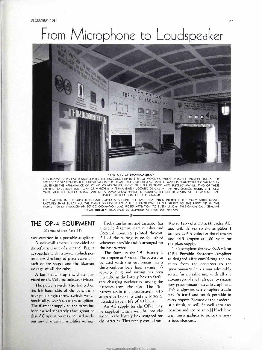
DECEMBER, 1934
From Microphone to Loudspeaker
"THE ABC OF BROADCASTING"
THIS DRAMATIC DISPLAY DEMONSTRATES THE PROGRESS. STEP BY STEP, OF VOICE OR MUSIC FROM THE MICROPHONE AT THE BROADCAST STATION TO THE LOUDSPEAKER IN THE HOME. THE CATHODE -RAY OSCILLOGRAPH IS EMPLOYED TO GRAPHICALLY ILLUSTRATE THE APPEARANCE OF SOUND WAVES WHICH HAVE BEEN TRANSFORMED INTO ELECTRIC WAVES. TWO OF THESE
EXHIBITS HAVE BEEN BUILT, ONE OF WHICH IS A PERMANENTLY LOCATED DISPLAY AT THE NBC STUDIOS, RADIO CITY, NEW YORK, AND THE OTHER FORMS PART OF A ROAD SHOW WHICH IS TOURING THE UNITED STATES AT THE PRESENT TIME.
UNDER THE DIRECTION OF H. P. KASNER.
THE CAPTION IN THE UPPER LEFT -HAND CORNER SETS FORTH THE FACT THAT "RCA VICTOR IS THE ONLY RADIO MANU- FACTURER THAT BUILDS ALL THE RADIO EQUIPMENT FROM THE MICROPHONE IN THE STUDIO TO THE RADIO SET IN THE
HOME." ONLY THROUGH PERFECT CO- ORDINATION AND PROPER ATTENTION TO EVERY LINK IN THIS CHAIN CAN GENUINE "HIGH FIDELITY" PROGRAMS BE DELIVERED AT THEIR DESTINATION
THE OP -4 EQUIPMENT (Continued from Page 13)
tant criterion in a portable amplifier. A volt -milliameter is provided on
the left -hand side of the panel, Figure 2, together with its switch which per- mits the checking of plate current in
each of the stages and the filament voltage of all the tubes.
A lamp and lamp shield are pro- vided on theVolume Indicator Meter.
The power switch, also located on the left -hand side of the panel, is a
four -pole single -throw switch which breaks all power leads to the amplifier. The filament supply to the tubes has been carried separately throughout so
that AC operation may be used with- out any changes in amplifier wiring.
o
Each transformer and capacitor has a circuit diagram, part number and electrical constants printed thereon. All of the wiring is neatly cabled wherever possible and is arranged for the best service.
The drain on the "A" battery is
one ampere at 6 volts. The battery to be used with this equipment has a
thirty -eight- ampere hour rating. A separate plug and wiring has been provided in the battery box to facili- tate charging without removing the batteries from the box. The "B" battery drain is approximately .015 ampere at 180 volts and the batteries intended have a life of 40 hours.
An AC supply for the OP -4 may be supplied which will fit into the space in the battery box assigned for the batteries. This supply works from
105 to 125 volts, 50 to 60 cycles AC, and will deliver to the amplifier 1
ampere at 6.3 volts for the filaments and .015 ampere at 180 volts for the plate supply.
Thiscompletesthe new RCAVictor OP -4 Portable Broadcast Amplifier as designed after considering the an- swers from the operators to the questionnaires. It is a unit admirably suited for portable use, with all the advantages of the high -quality system now predominant in studio amplifiers. This equipment is a complete studio rack in itself and yet is portable in
every respect. Because of the modern- istic finish, it will fit well into any location and not be an odd black box with queer gadgets to incite the mys- terious elements.
www.americanradiohistory.com
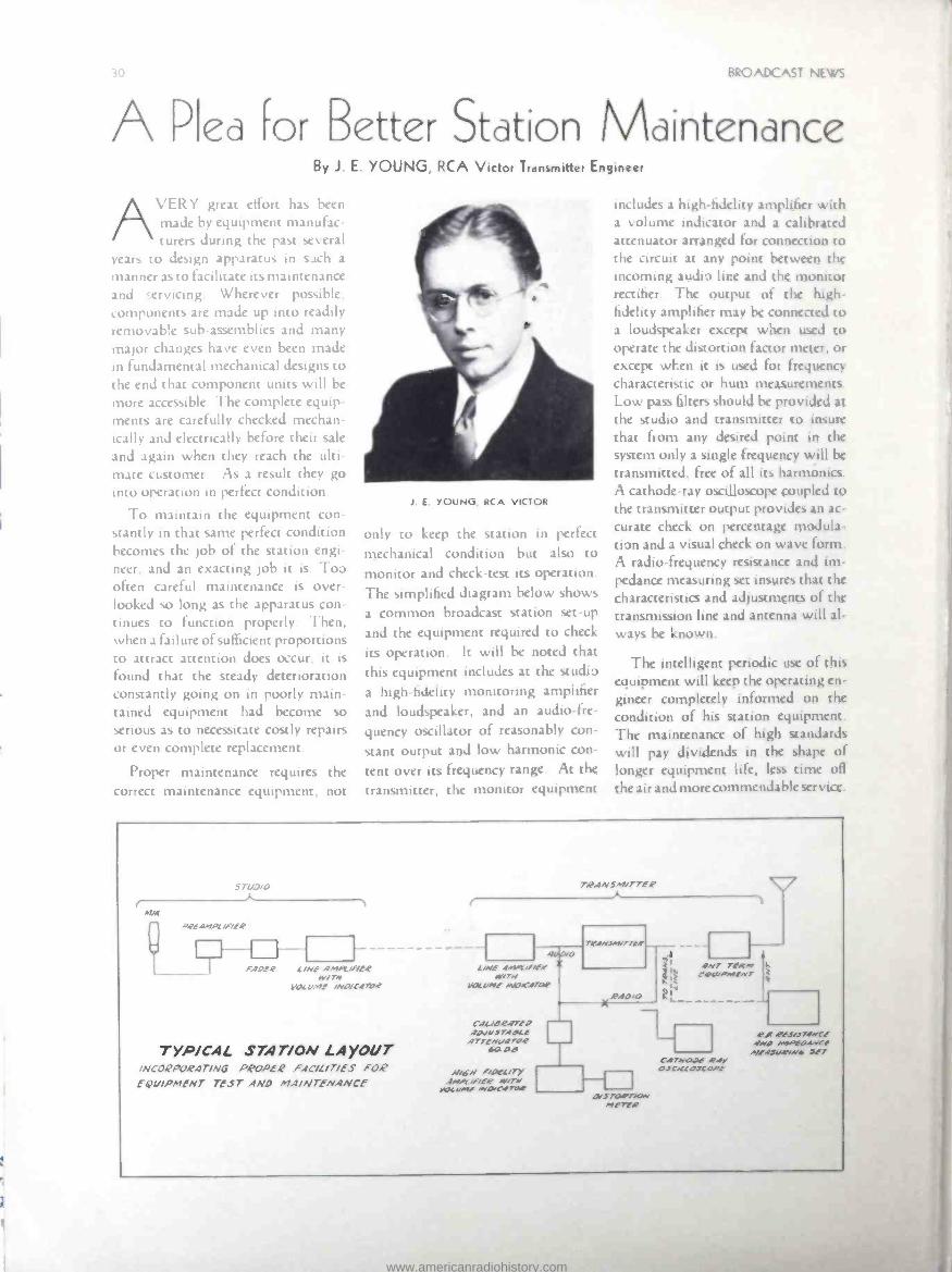
BRO ADC AS '
A Pled For Better Station Maintenance By J E YOUNG, RCA Victor Tranwmttl, Engineer
A\'I R'ï grist effort has been made by equipment manufac- turers during the past several
tears to design apparatus in such a
manner as to facilitate its maintenance and ervicing Wherever possible, components are made up into readily removah!e sub -assemblies and many major changes have even been made In fundamental mechanical designs co
the end that component units will he
more accessible The complete equip- ments are carefully checked mechan- ically and electrically before their sale
and again when they reach the ulti- mate customer. As a result they go into operation In perfect condition.
To maintain the equipment con- stantly in that same perfect condition becomes the µ1b of the station engi- neer, and an exacting job it is Too often careful maintenance is over- looked so lung as the apparatus con- tinues to function properly. Then, when a failure of sufficient proportions to attract attention does occur, it is
found that the steady deterioration constantly going on in poorly main- tained equipment had become so serious as to necessitate costly repairs or even complete replacement.
Proper maintenance requires the correct maintenance equipment, not
1 E YOUNG, RCA VICTOR
only to keep the station in perfect
mechanical condition but also to monitor and check -test its operation.
The simplified diagram below shows
a common broadcast station set -up
and the equipment required to check
its operation. It will he noted that this equipment includes at the studio
a high -fidelity monitoring amplifier
and loudspeaker, and an audio -fre-
quency oscillator of reasonably con-
stant output and low harmonic con-
tent over its frequency range. At the
transmitter, the monitor equipment
includes a high-fidelity amplifier with a volume indicator and a calibrated attenuator arranged for connection ro the circuit at any point between the incoming audio lire and the monitor rectifier. The output of the high -
fidelity amplifier may be conne:ted w a loudspeaker except when used w operate the distortion factor meter, or except wEen it is used for frequency characteristic or hum measurements Luw pass filters should he provided at the studio and transmitter to insure that from any desired point in the system only a single frequency will he
transmitted, free of all its harmonics. A cathode -ray oscilloscope coupled tu the transmitter output provides an ac-
curate check on percentage modula -
tion and a visual check on wave form. A radio - frequency resistance and im- pedance measuring set insures that the characteristics and adjustments of the transmission line and antenna will al-
ways he known.
The intelligent periodic use of this equipment will keep the operating en- gineer completely informed on the condition of his station equipment. The maintenance of high standards will pay dividends in the shape of longer equipment life, less time off
the air and mure (online ndahke service.
57Z'J /O
o4E.4MP[ iF/E4
i40_°R L/NE 4NKt/F/b? W/TN
l . L ,,ter /NO/C4704
TYP /CAL STAT /ON LAYOUT /NCOQPORAT /NG PROPER FAC /l /7 /ES FOR EQv /PMENT TEST ANO MA /NTENANCE
TQAN5M/TTER
L NE 445.1./EiEf N17N
pcvMf /4O.áITAf
CAL iGE.i7f 9 AOvsTlace ArreNuoroe saos
N/+ r/pfL/ry 4.//1is/E4 N/TN
yOCwf ,10/ c4rpP
TQINYIiTTE.f
RIO /O
tii 1
%<1 4N7 TEMA, A
vil fO(//IMEN7 t Á4
L
C47NO4E 4.4y OSC/L[OJCPPE
.215 70PTiCA` ME TEE.
4 f 4'ES.174NCf 4N0 /M9fO4NCE
A7f4S4/N(, 3E7
www.americanradiohistory.com

DECEMBER, 1934
British Television Commission Visits
C dmcen, \. J.
BRITISH TELEVISION COMMISSION HEADED BY LORD SELSDON LEFT TO RIGHT: MR. LITTLE, BRITISH GENERAL POST OFFICE; E. T. CUNNINGHAM, PRESIDENT RCA VICTOR COMPANY, F. W. PHILLIPS, UNDER SECRETARY, GENERAL POST OFFICE, DAVID SARNOFF, PRESIDENT RADIO CORPORATION OF AMERICA, LORD SELSDON, COLONEL A. S. ANGWIN, CHIEF ENGINEER, GENERAL POST OFFICE NOEL ASHBRIDGE, ASSISTANT CHIEF
ENGINEER, BRITISH BROADCASTING SYSTEM
DISTINGUISHED VISITORS ENJOY TOUR THROUGH "RADIO HEADQUARTERS"
ADISTINGUISHED group of British engineers headed by Lord Selsdon visited the
Camden laboratories of the RCA Victor Company today accompanied by Mr. DavidSarnoff, President of the Radio Corporation of America, and Mr. E. T. Cunningham, President of the RCA Victor Company. The Com- mission, which was appointed by the British General Post Office, under whose jurisdiction are all communi- cations services, is hereto make a study of television progress in this country.
The visitors included, besides Lord Selsdon, the Chairman, F. W. Phil-
SEE
IMPORTANT NOTICE ON
PAGE 32
-DON'T FAIL TO FILL OUT AND MAIL THE COUPON
lips, Under Secretary, British General Post Office; Colonel A. S. Angwin, Chief Engineer, General Post Office; Noel Ashbridge, Assistant Chief En- gineer ache British Broadcasting Sys- tem. While here, the group viewed the experimental television laborato- ries of the RCA Victor Company un- der the guidance of W. R. G. Baker, Vice President and General Manager, and Dr. V. K. Zworykin. Later they inspected the new radio facsimile pic- ture transmission apparatus and some of the "Magic Brain" radio factories.
www.americanradiohistory.com

DETROIT ORCHESTRA HALL
(Continued from Page 15)
can, during rehearsals, cut the program coming from the stage, energize the talk -back microphone, and converse with the performers by means of the loudspeaker located backstage. When the switch operating the talk -back circuit is thrown to the talk -back po- sition, relays simultaneously discon- nect the monitor speaker in the control booth, connect the talk -back speaker located backstage, disconnect the stage microphone and connect the talk -back microphone to the program amplifier. This sequence of events prevents any
possibility of an audio frequency feed- back between loudspeakers and micro- phones.
The function of the program switch previously mentioned is to connect the input of the program amplifier, and hence the monitor amplifiers and their attendant loudspeakers, either to the output of the stage microphones or to a cue circuit, from which the "air" program preceding or succeed- ing the auditorium presentation may be heard. The incoming line, upon which the cue is received, is provided with a suitable matching coil and a
variable pad, as indicated in the block diagram.
IMPORTANT NOTICE to Our Readers
Duc to the increased circulation of BROADCAST NEWS, we wish to an- nounce our new distribution policy. Hereafter, one copy only of BROADCAST NEWS will be mailed direct from "Radio Headquarters" to every Broadcast Station in the United States.
Members of the personnel of each station may obtain individual copies through- out 1935 upon written request to the local RCA Victor District Office, as listed herewith. Changes of address should be included.
We trust that our present readers will understand the necessity for this new system of distribution and will cooperate by communicating directly with our District Offices, as we do not wish any interested persons to miss an issue.
Paid subscriptions will of course continue to be honored. 1- EASTERN DIsTRIcr -T. A. Smith, Manager, 153 E. 24th St., New York City
Maine Connecticut Maryland Vermont New York North Carolina (Broadcast) New Hampshire Puerto Rico West Virginia Massachusetts New Jersey Delaware Rhode Island Pennsylvania Virginia
2- CENTRAI. DISTRICT -H. C. Vance, Manager, 111 North Canal St., Chicago, Ill. North Dakota Iowa South Dakota Minnesota Nebraska Illinois Wisconsin Indiana Missouri
Kentucky Ohio Michigan Kansas City (Kansas)
3- WESTERN DISTRICT -W. H. Beltz, Manager, 235 Montgomery St., San Francisco, Calif.
Alaska (Police) Montana Wyoming
Washington Oregon California Idaho
Nevada Hawaii (Police) Utah Arizona
4- SOUTHWESTERN DISTRICT -W. M. Witty, Mgr., Santa Fe Bldg., Dallas, Texas
Texas Louisiana Kansas Oklahoma (Except New Orleans) (Except Kansas City) Arkansas Colorado New Mexico
5- SOUTHEASTERN DISTRICT-B. Adler, Mgr., 144 Walton St., N. W., Atlanta, Ga.
Tennessee South Carolina North Carolina Georgia
(Police) Alabama
Mississippi Florida New Orleans (La.)
BROADS/1ST NEWS COUPON Date RCA VICTOR Co., INC.
(Address to your local District Office)
I wish to be placed on your mailing list CO regularly receive BROADCAST NEWS as issued during 1935, without charge.
I am connected wich Station , located at..
in the capacity of
BROADCAST NEWS
The various component circuit ele- ments which go toward making up the completed circuit connect to each other through jacks which, when nor- mally closed, complete the circuit in the desired manner. This is clearly shown in the accompanying block diagram of the equipment layout. This arrangement provides a jack strip free from patchcords during all nor- mal operations. However, in the event of the failure of any circuit ele- ment, it may be jumped out cf the circuit by a patchcord, or a similar element may be "patched" into the circuit. The liberal use of "normal through" jacks provides for maxi- mum flexibility, minimum of pro- gram interruptions, and for ease in locating defective equipment.
The control room contains a single rack of equipment, a mixer console, a
talk -back microphone and regular tele- phone facilities. The monitor speaker, an RCA UZ -4209, is mounted at one end of the room behind a large baffle. The talk -back loudspeaker, previously mentioned, is mounted backstage in the wings in a similar manner.
As is seen in the photograph, the equipment mounted on the rack con- sists of a meter panel at the top, an RCA Victor 40 -C program amplifier immediately underneath, then a panel carrying the volume controls and matching coils, next a "low- level" jack strip, followed by a "high- level" jack strip, below which are mounted the two RCA Victor AA- 4194 -B
monitor amplifiers. At the very bot- tom of the rack is mounted a panel which carries the terminal block strips, to which all wiring cables are brought.
A detail of construction, which is
commonly employed in the assembly
of such speech input equipment racks,
is the use of terminal blocks at the
base of the rack.
In order to facilitate wiring from the mixer console to the rack and to the various wall boxes, a trench was
provided under the floor of the control room for the various wires and cables.
The entire equipment was assembled,
wired and tested in New York City,
crated and shipped to Detroit, and
placed in operation in a little more
than an hour's time after arrival.
www.americanradiohistory.com

0
THE LATEST ADDITIO\ TO U \CLE SAM'S \AVY
irr Alm r 4: i .
t,. lit
1
MINIENIO r.. -
U. S. S. "TUSCALOOSA"-A PRODUCT OF CAMDEN, NEW JERSEY
IN ADDITION TO THE RADIO COMMUNICATION EQUIPMENT, THE RCA VICTOR COMPANY, INC., ;UPPLIED THE U. S. S.
"TUSCALOOSA" WI TH SPECIALLY DESIGNED SOUND MOTION PICTURE EOU! ?MENT, AND THE ANTENAPLEX SYSTEM
(FOR MULTIPLE BROADCAST RECEIVERS). CHIEF RADIOMAN ALLAN SINCLAIR, U. S. N. R., OF THE RCA VICTOR TEST
DEPARTMENT, WENT OUT IN THE TUSCALOOSA AS OPERATOR ON HER TRIAL TRIP TO ROCKLAND, MAINE
D
1
1
www.americanradiohistory.com
A CHRISTMAS PRESENT FOR YOU ONE WHICH WILL LAST THROUGHOUT 1935
SEE fA
IMPORTANT NOTICE
ON PAGE 32
- FILL OUT AND
MAIL THE COUPON
Form 9157 itq IjIi
www.americanradiohistory.com