bracing tilt-up panels · 79 meadow burke braces are designed for use with the meadow burke brace...
TRANSCRIPT
77
www.MeadowBurke.com 877-518-7665 MB1109
Tilt-Up Manual
���
���
���
�� �
!��F
�����
BRACING TILT-UP PANELS
www.MeadowBurke.com 877-518-7665
Tilt-Up Manual
78
A tilt-up panel is not a completed wall immediately upon
lifting. Braces are necessary to resist wind forces until
permanent connections are made.
A number of variables will effect the amount of force Meadow
Burke braces must resist. The amount of lateral pressure on
newly erected tilt-up panels will vary with wind velocity, the
surface area of the panel and the presence or absence of
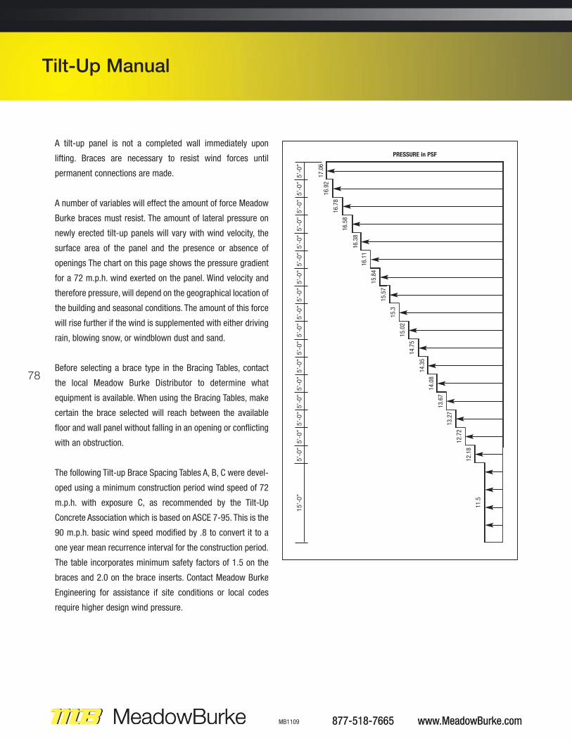
openings The chart on this page shows the pressure gradient
for a 72 m.p.h. wind exerted on the panel. Wind velocity and
therefore pressure, will depend on the geographical location of
the building and seasonal conditions. The amount of this force
will rise further if the wind is supplemented with either driving
rain, blowing snow, or windblown dust and sand.
Before selecting a brace type in the Bracing Tables, contact
the local Meadow Burke Distributor to determine what
equipment is available. When using the Bracing Tables, make
certain the brace selected will reach between the available
floor and wall panel without falling in an opening or conflicting
with an obstruction.
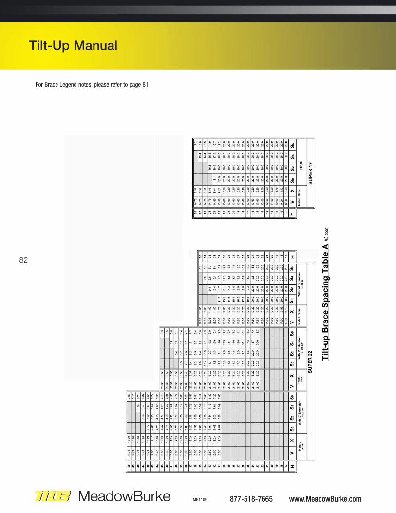
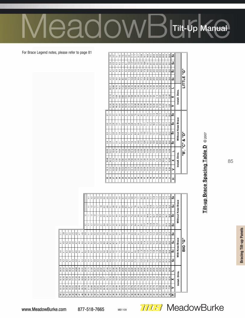
The following Tilt-up Brace Spacing Tables A, B, C were devel-
oped using a minimum construction period wind speed of 72
m.p.h. with exposure C, as recommended by the Tilt-Up
Concrete Association which is based on ASCE 7-95. This is the
90 m.p.h. basic wind speed modified by .8 to convert it to a
one year mean recurrence interval for the construction period.
The table incorporates minimum safety factors of 1.5 on the
braces and 2.0 on the brace inserts. Contact Meadow Burke
Engineering for assistance if site conditions or local codes
require higher design wind pressure.
877-518-7665 www.MeadowBurke.com MB1109
Tilt-Up Manual
5’-0”
5’-0”
5’-0”
5’-0”
5’-0”
5’-0”
5’-0”
5’-0”
5’-0”
5’-0”
5’-0”
5’-0”
5’-0”
5’-0”
5’-0”
5’-0”
5’-0”
15’-0”
17.06
PRESSURE in PSF
16.92
16.78
16.58
16.38
16.11
15.84
15.57
15.3
15.02
14.75
14.35
14.08
13.67
13.27
12.72
12.18
11.5
877-518-7665 www.MeadowBurke.com
Tilt-Up Manual
79
Meadow Burke braces are designed for use with the Meadow Burke Brace Badger, Slam Anchor, Super Bolt, M-B Brace Bolt, or
with cast-in-place B-75, BI-75 and BG-75 coil inserts only. The use of other types of inserts may reduce the capacity of the
bracing system and therefore should not be used. In order to develop the full capacity of the brace inserts, the inserts must be
embedded in concrete with 2,500 psi minimum concrete compressive strength, 5 inch minimum embedment and located 1 foot
minimum from all concrete edges. Lesser embedments or lower concrete strengths will reduce the capacity of the brace insert and
may reduce the allowable brace spacings shown in the tables or on the panel erection details. Meadow Burke does not recommend
the use of expansion type inserts for attaching tilt-up braces and assumes no responsibility if used.
To achieve the spacings shown in the brace tables or on the panel erection details, the braces must be anchored to a concrete floor
slab, footing or deadman with sufficient area, weight and strength to resist the applied brace loads. The braces are designed for
attachment at top of floor slab elevation unless noted otherwise on the details. The floor slab has not been checked or designed by
Meadow Burke. Using floor slabs, footings or deadmen of insufficient size or strength may result in failure of the brace system before
the design wind load is reached. It is the users responsibility to have a qualified professional engineer design the floor slab, footing
or deadman to insure that they are adequate to anchor the braces for this application. To assist the engineer, the applied design
concentric brace load as determined by Meadow Burke Engineering for each brace is indicated on the panel detail sheets.
The brace information shown herein reflects spacings for the resistance of wind load only. The effect of construction live loads, soil
backfill loads, vertical and lateral loads, etc., have not been considered in the design of the brace tables or brace information shown
on the erection details. It is the responsibility of others to determine the effect of such loads and provide additional bracing as required
to support the panels.
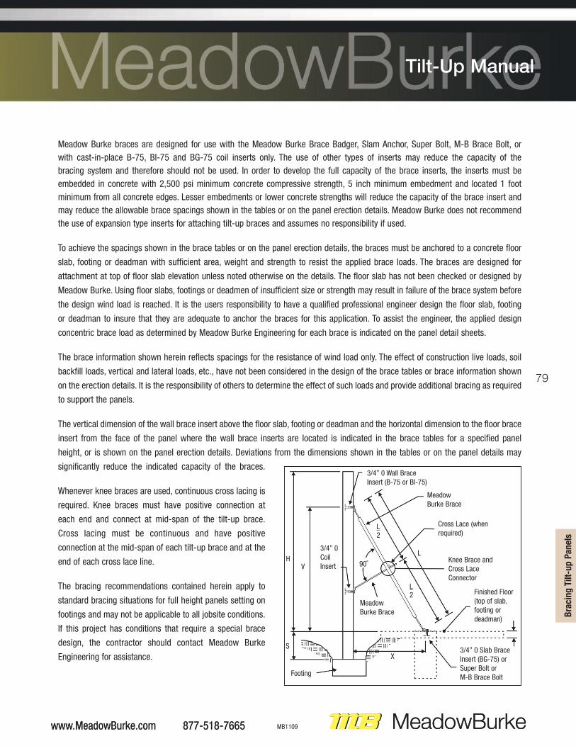
The vertical dimension of the wall brace insert above the floor slab, footing or deadman and the horizontal dimension to the floor brace
insert from the face of the panel where the wall brace inserts are located is indicated in the brace tables for a specified panel
height, or is shown on the panel erection details. Deviations from the dimensions shown in the tables or on the panel details may
significantly reduce the indicated capacity of the braces.
Whenever knee braces are used, continuous cross lacing is
required. Knee braces must have positive connection at
each end and connect at mid-span of the tilt-up brace.
Cross lacing must be continuous and have positive
connection at the mid-span of each tilt-up brace and at the
end of each cross lace line.
The bracing recommendations contained herein apply to
standard bracing situations for full height panels setting on
footings and may not be applicable to all jobsite conditions.
If this project has conditions that require a special brace
design, the contractor should contact Meadow Burke
Engineering for assistance.
www.MeadowBurke.com 877-518-7665 MB1109
Tilt-Up Manual
���
���
���
�� �
!��F
�����
3/4” 0 Wall BraceInsert (B-75 or BI-75)
MeadowBurke Brace
Knee Brace andCross LaceConnector
Finished Floor (top of slab, footing or deadman)
Cross Lace (whenrequired)
MeadowBurke Brace
Footing
HV 90˚
L2
3/4” 0CoilInsert
L2
X
L
S3/4” 0 Slab BraceInsert (BG-75) orSuper Bolt or M-B Brace Bolt
www.MeadowBurke.com 877-518-7665
Tilt-Up Manual
80
BRACING GUIDELINES
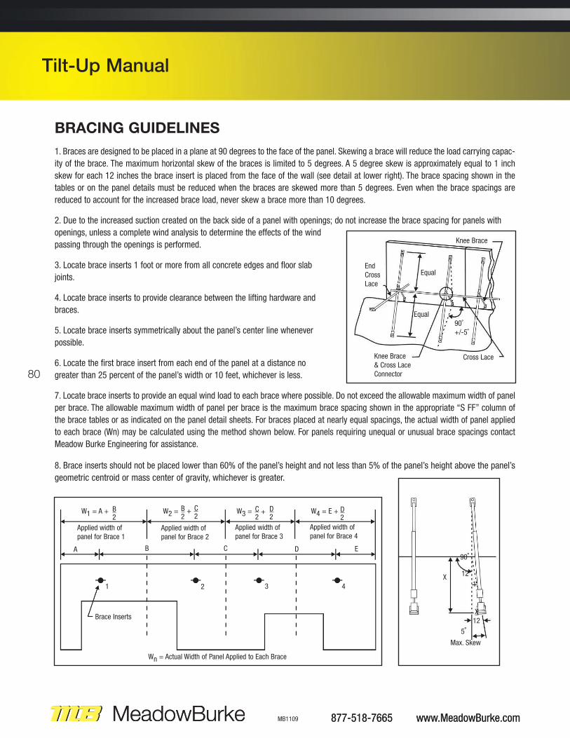
1. Braces are designed to be placed in a plane at 90 degrees to the face of the panel. Skewing a brace will reduce the load carrying capac-
ity of the brace. The maximum horizontal skew of the braces is limited to 5 degrees. A 5 degree skew is approximately equal to 1 inch
skew for each 12 inches the brace insert is placed from the face of the wall (see detail at lower right). The brace spacing shown in the
tables or on the panel details must be reduced when the braces are skewed more than 5 degrees. Even when the brace spacings are
reduced to account for the increased brace load, never skew a brace more than 10 degrees.
2. Due to the increased suction created on the back side of a panel with openings; do not increase the brace spacing for panels with
openings, unless a complete wind analysis to determine the effects of the wind
passing through the openings is performed.
3. Locate brace inserts 1 foot or more from all concrete edges and floor slab
joints.
4. Locate brace inserts to provide clearance between the lifting hardware and
braces.
5. Locate brace inserts symmetrically about the panel’s center line whenever
possible.
6. Locate the first brace insert from each end of the panel at a distance no
greater than 25 percent of the panel’s width or 10 feet, whichever is less.
7. Locate brace inserts to provide an equal wind load to each brace where possible. Do not exceed the allowable maximum width of panel
per brace. The allowable maximum width of panel per brace is the maximum brace spacing shown in the appropriate “S FF” column of
the brace tables or as indicated on the panel detail sheets. For braces placed at nearly equal spacings, the actual width of panel applied
to each brace (Wn) may be calculated using the method shown below. For panels requiring unequal or unusual brace spacings contact
Meadow Burke Engineering for assistance.
8. Brace inserts should not be placed lower than 60% of the panel’s height and not less than 5% of the panel’s height above the panel’s
geometric centroid or mass center of gravity, whichever is greater.
877-518-7665 www.MeadowBurke.com MB1109
Tilt-Up Manual
Knee Brace
EndCrossLace
Cross Lace
Equal
Equal
Knee Brace & Cross LaceConnector
90˚+/-5˚
Max. Skew
5˚
90˚
X12
X12
1
W1 = A +
Applied width ofpanel for Brace 1
Applied width ofpanel for Brace 2
Applied width ofpanel for Brace 3
Applied width ofpanel for Brace 4
W2 = W3 = W4 = E +
Brace Inserts
Wn = Actual Width of Panel Applied to Each Brace
A B C D E
B2
C2
D2
D2
B +2
C +2
1 2 3 4
877-518-7665 www.MeadowBurke.com
Tilt-Up Manual
81
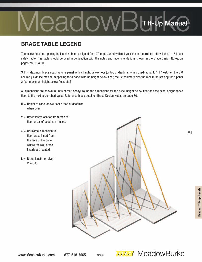
BRACE TABLE LEGEND
The following brace spacing tables have been designed for a 72 m.p.h. wind with a 1 year mean recurrence interval and a 1.5 brace
safety factor. The table should be used in conjunction with the notes and recommendations shown in the Brace Design Notes, on
pages 78, 79 & 80.
SFF = Maximum brace spacing for a panel with a height below floor (or top of deadman when used) equal to “FF” feet. [ie., the S 0
column yields the maximum spacing for a panel with no height below floor, the S2 column yields the maximum spacing for a panel
2 foot maximum height below floor, etc.]
All dimensions are shown in units of feet. Always round the dimensions for the panel height below floor and the panel height above
floor, to the next larger chart value. Reference brace detail on Brace Design Notes, on page 80.
H = Height of panel above floor or top of deadman
when used.
V = Brace insert location from face of
floor or top of deadman if used.
X = Horizontal dimension to
floor brace insert from
the face of the panel
where the wall brace
inserts are located.
L = Brace length for given
V and X.
www.MeadowBurke.com 877-518-7665 MB1109
Tilt-Up Manual
���
���
���
�� �
!��F
�����
www.MeadowBurke.com 877-518-7665
Tilt-Up Manual
82
877-518-7665 www.MeadowBurke.com MB1109
Tilt-Up Manual
877-518-7665 www.MeadowBurke.com
Tilt-Up Manual
For Brace Legend notes, please refer to page 81

83
www.MeadowBurke.com 877-518-7665 MB1109
Tilt-Up Manual
���
���
���
�� �
!��F
�����
www.MeadowBurke.com 877-518-7665
Tilt-Up Manual
For Brace Legend notes, please refer to page 81
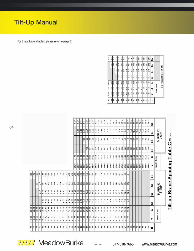
84
877-518-7665 www.MeadowBurke.com MB1109
Tilt-Up Manual
877-518-7665 www.MeadowBurke.com
Tilt-Up Manual
For Brace Legend notes, please refer to page 81
85
www.MeadowBurke.com 877-518-7665 MB1109
Tilt-Up Manual
���
���
���
�� �
!��F
�����
www.MeadowBurke.com 877-518-7665
Tilt-Up Manual
For Brace Legend notes, please refer to page 81
86
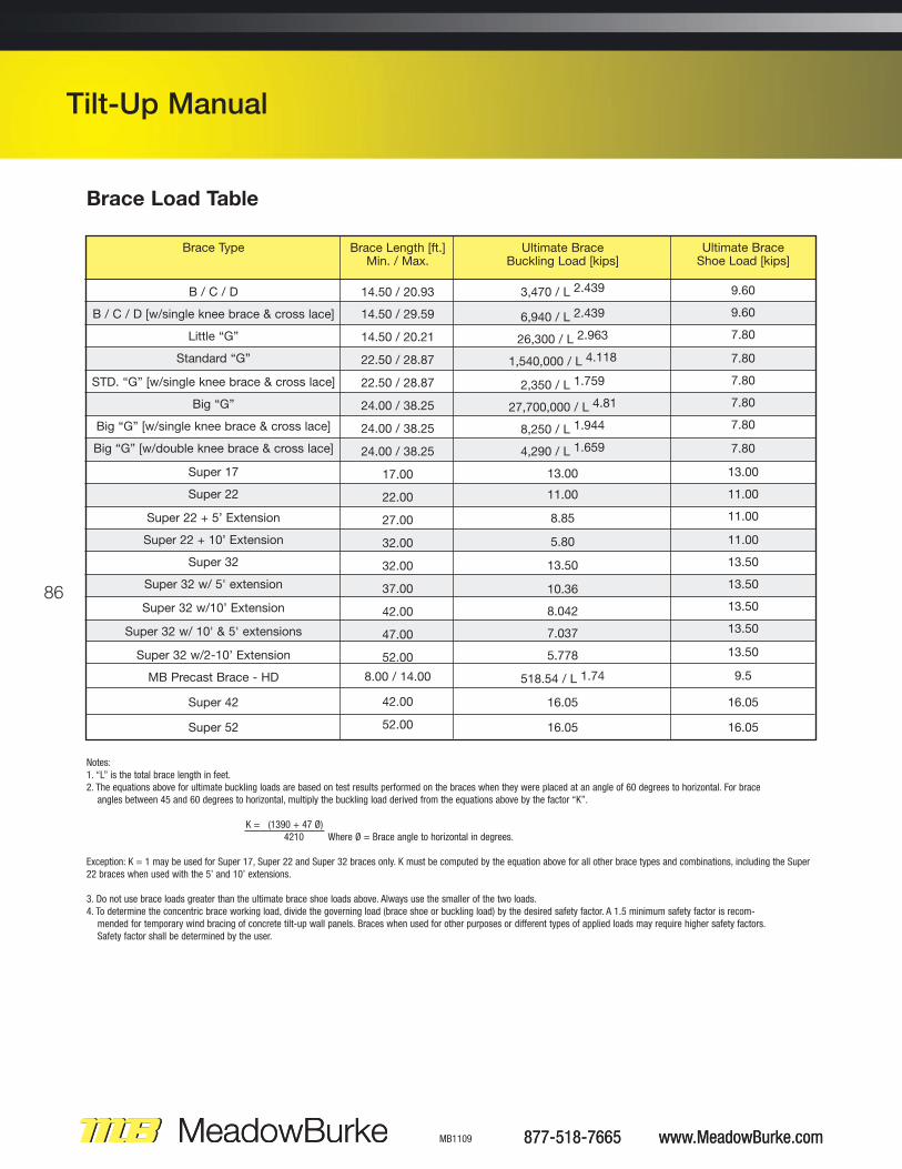
Notes:1. “L” is the total brace length in feet.2. The equations above for ultimate buckling loads are based on test results performed on the braces when they were placed at an angle of 60 degrees to horizontal. For brace angles between 45 and 60 degrees to horizontal, multiply the buckling load derived from the equations above by the factor “K”.
K = (1390 + 47 Ø)4210 Where Ø = Brace angle to horizontal in degrees.
Exception: K = 1 may be used for Super 17, Super 22 and Super 32 braces only. K must be computed by the equation above for all other brace types and combinations, including the Super22 braces when used with the 5’ and 10’ extensions.
3. Do not use brace loads greater than the ultimate brace shoe loads above. Always use the smaller of the two loads.4. To determine the concentric brace working load, divide the governing load (brace shoe or buckling load) by the desired safety factor. A 1.5 minimum safety factor is recom-mended for temporary wind bracing of concrete tilt-up wall panels. Braces when used for other purposes or different types of applied loads may require higher safety factors. Safety factor shall be determined by the user.
877-518-7665 www.MeadowBurke.com MB1109
Tilt-Up Manual
Brace Load Table
Brace Length [ft.]Min. / Max.
14.50 / 20.93
14.50 / 29.59
14.50 / 20.21
22.50 / 28.87
22.50 / 28.87
24.00 / 38.25
24.00 / 38.25
24.00 / 38.25
17.00
22.00
27.00
32.00
32.00
37.00
42.00
47.00
52.00
8.00 / 14.00
42.00
52.00
Brace Type
B / C / D
B / C / D [w/single knee brace & cross lace]
Little “G”
Standard “G”
STD. “G” [w/single knee brace & cross lace]
Big “G”
Big “G” [w/single knee brace & cross lace]
Big “G” [w/double knee brace & cross lace]
Super 17
Super 22
Super 22 + 5’ Extension
Super 22 + 10’ Extension
Super 32
Super 32 w/ 5' extension
Super 32 w/10’ Extension
Super 32 w/ 10' & 5' extensions
Super 32 w/2-10’ Extension
MB Precast Brace - HD
Super 42
Super 52
Ultimate BraceBuckling Load [kips]
3,470 / L 2.439
6,940 / L 2.439
26,300 / L 2.963
1,540,000 / L 4.118
2,350 / L 1.759
27,700,000 / L 4.81
8,250 / L 1.944
4,290 / L 1.659
13.00
11.00
8.85
5.80
13.50
10.36
8.042
7.037
5.778
518.54 / L 1.74
16.05
16.05
Ultimate BraceShoe Load [kips]
9.60
9.60
7.80
7.80
7.80
7.80
7.80
7.80
13.00
11.00
11.00
11.00
13.50
13.50
13.50
13.50
13.50
9.5
16.05
16.05
877-518-7665 www.MeadowBurke.com
Tilt-Up Manual
87
www.MeadowBurke.com 877-518-7665 MB1109
Tilt-Up Manual
���
���
���
�� �
!��F
�����
TILT-UP BRACING HARDWARE
www.MeadowBurke.com 877-518-7665
Tilt-Up Manual
88
MEADOW BURKE BRACES
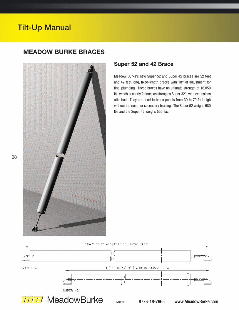
Super 52 and 42 Brace
Meadow Burke's new Super 52 and Super 42 braces are 52 feet
and 42 feet long, fixed-length braces with 18'' of adjustment for
final plumbing. These braces have an ultimate strength of 16,050
lbs which is nearly 2 times as strong as Super 32's with extensions
attached. They are used to brace panels from 39 to 79 feet high
without the need for secondary bracing. The Super 52 weighs 680
lbs and the Super 42 weighs 550 lbs.
877-518-7665 www.MeadowBurke.com MB1109
Tilt-Up Manual
877-518-7665 www.MeadowBurke.com
Tilt-Up Manual
89
www.MeadowBurke.com 877-518-7665 MB1109
Tilt-Up Manual
���
���
���
�� �
!��F
�����
MEADOW BURKE BRACES
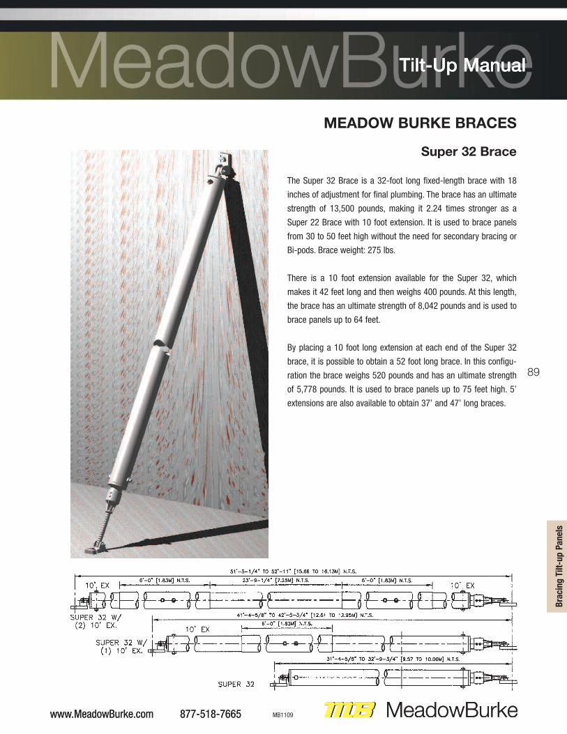
Super 32 Brace
The Super 32 Brace is a 32-foot long fixed-length brace with 18
inches of adjustment for final plumbing. The brace has an ultimate
strength of 13,500 pounds, making it 2.24 times stronger as a
Super 22 Brace with 10 foot extension. It is used to brace panels
from 30 to 50 feet high without the need for secondary bracing or
Bi-pods. Brace weight: 275 lbs.
There is a 10 foot extension available for the Super 32, which
makes it 42 feet long and then weighs 400 pounds. At this length,
the brace has an ultimate strength of 8,042 pounds and is used to
brace panels up to 64 feet.
By placing a 10 foot long extension at each end of the Super 32
brace, it is possible to obtain a 52 foot long brace. In this configu-
ration the brace weighs 520 pounds and has an ultimate strength
of 5,778 pounds. It is used to brace panels up to 75 feet high. 5’
extensions are also available to obtain 37’ and 47’ long braces.
www.MeadowBurke.com 877-518-7665
Tilt-Up Manual
90
877-518-7665 www.MeadowBurke.com MB1109
Tilt-Up Manual
877-518-7665 www.MeadowBurke.com
Tilt-Up Manual
MEADOW BURKE BRACES
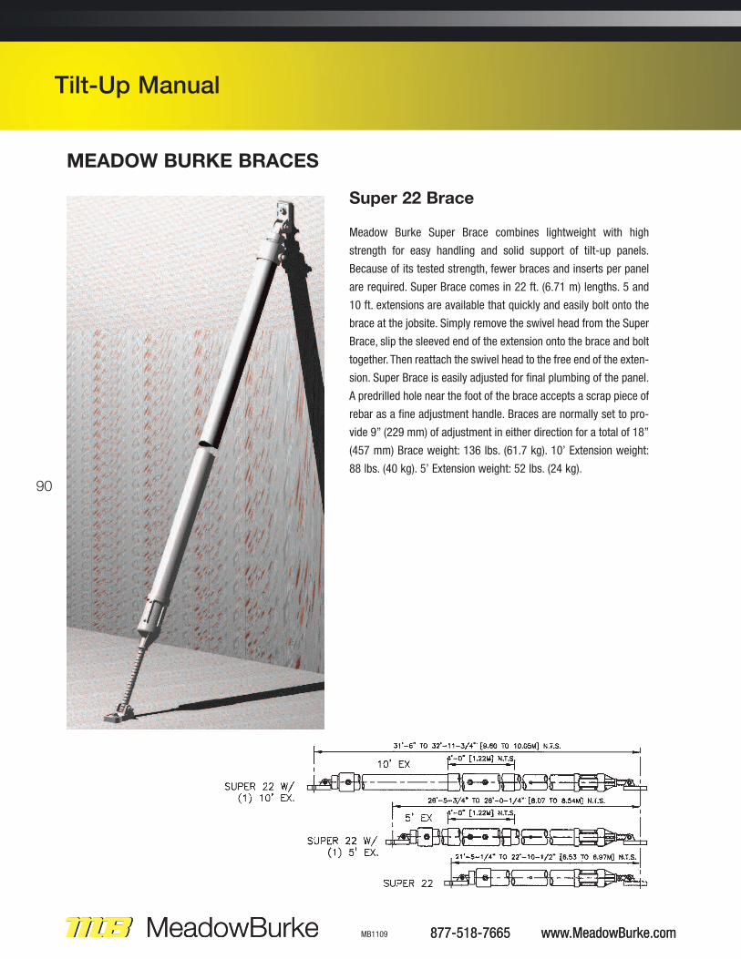
Super 22 Brace
Meadow Burke Super Brace combines lightweight with high
strength for easy handling and solid support of tilt-up panels.
Because of its tested strength, fewer braces and inserts per panel
are required. Super Brace comes in 22 ft. (6.71 m) lengths. 5 and
10 ft. extensions are available that quickly and easily bolt onto the
brace at the jobsite. Simply remove the swivel head from the Super
Brace, slip the sleeved end of the extension onto the brace and bolt
together. Then reattach the swivel head to the free end of the exten-
sion. Super Brace is easily adjusted for final plumbing of the panel.
A predrilled hole near the foot of the brace accepts a scrap piece of
rebar as a fine adjustment handle. Braces are normally set to pro-
vide 9” (229 mm) of adjustment in either direction for a total of 18”
(457 mm) Brace weight: 136 lbs. (61.7 kg). 10’ Extension weight:
88 lbs. (40 kg). 5’ Extension weight: 52 lbs. (24 kg).
91
www.MeadowBurke.com 877-518-7665 MB1109
Tilt-Up Manual
���
���
���
�� �
!��F
�����
www.MeadowBurke.com 877-518-7665
Tilt-Up Manual
MEADOW BURKE BRACES
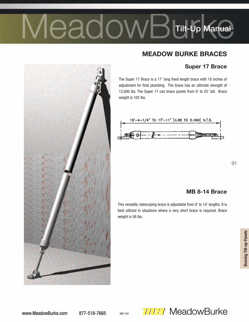
Super 17 Brace
The Super 17 Brace is a 17’ long fixed length brace with 18 inches of
adjustment for final plumbing. The brace has an ultimate strength of
13,000 lbs. The Super 17 can brace panels from 9’ to 25’ tall. Brace
weight is 105 lbs.
MB 8-14 Brace
This versatile, telescoping brace is adjustable from 8’ to 14’ lengths. It is
best utilized in situations where a very short brace is required. Brace
weight is 58 lbs.

92
877-518-7665 www.MeadowBurke.com MB1109
Tilt-Up Manual
COIL INSERTS
Meadow Burke’s Brace Inserts have been an industry standard for the past three decades. These solid bolted connections haveproven the strength and security of this system on thousands of job sites around the country.
For unshakable reliability the Meadow Burke Coil System is an excellent choice.
B-75 WALL BRACE INSERT3/4” diameter coil insert height is 1/2” less than panel thickness. Available in 1/2”increments from 5” through 12”.
Yellow Easy-See Cap has antennae to make locatinginserts quicker and easier.
Clear plastic feetobscure insert on theback side of the panel.
0.262 Dia.
Conc. Thick.in inches
5”
5-1/2”
6”
6-1/4”
6-1/2”
7”
7-1/4”
7-1/2”
8”
8-1/4”
8-1/2”
9”
9-1/4”
9-1/2”
10”
10-1/2”
11”
11-1/4”
11-1/2”
12”
WORKING LOADS IN LBS. IN 2500 PSICONCRETE, 2.0:1 SAFETY FACTOR
Face Shear
8,200
10,150
10,150
10,150
10,150
10,150
10,150
10,150
10,150
10,150
10,150
10,150
10,150
10,150
10,150
10,150
10,150
10,150
10,150
10,150
FaceTension
7,800
9,625
10,150
10,150
10,150
10,150
10,150
10,150
10,150
10,150
10,150
10,150
10,150
10,150
10,150
10,150
10,150
10,150
10,150
10,150
ItemNumber
B75050
B75055
B75060
B75062
B75065
B75070
B75072
B75075
B75080
B75082
B75085
B75090
B75092
B75095
B75100
B75105
B75110
B75112
B75115
B75120
0.262 Dia.
Clearplastic feet
Yellow Easy-SeeCap has antennaeto make locatinginserts quicker andeasier.
4-3/4”
Conc. Thick.in inches
Inverted
WORKING LOADS IN LBS. IN 2500 PSICONCRETE, 2.0:1 SAFETY FACTOR
Face Shear
10,150
FaceTension
9,625
ItemNumber
BII75
BII-75 INVERTED WALL
BRACE INSERT3/4” diameter coil insert - Available in size shown only.
The minimum edge distance required to obtain the rated loadsfor face applications is 12 inches.
93
www.MeadowBurke.com 877-518-7665 MB1109
Tilt-Up Manual
���
���
���
�� �
!��F
�����
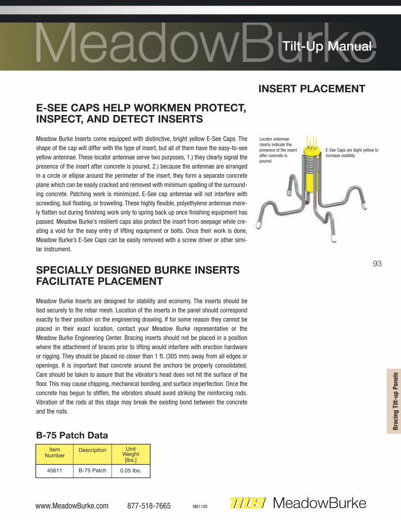
E-SEE CAPS HELP WORKMEN PROTECT,INSPECT, AND DETECT INSERTS
Meadow Burke Inserts come equipped with distinctive, bright yellow E-See Caps. The
shape of the cap will differ with the type of insert, but all of them have the easy-to-see
yellow antennae. These locator antennae serve two purposes, 1.) they clearly signal the
presence of the insert after concrete is poured, 2.) because the antennae are arranged
in a circle or ellipse around the perimeter of the insert, they form a separate concrete
plane which can be easily cracked and removed with minimum spalling of the surround-
ing concrete. Patching work is minimized. E-See cap antennae will not interfere with
screeding, bull floating, or troweling. These highly flexible, polyethylene antennae mere-
ly flatten out during finishing work only to spring back up once finishing equipment has
passed. Meadow Burke’s resilient caps also protect the insert from seepage while cre-
ating a void for the easy entry of lifting equipment or bolts. Once their work is done,
Meadow Burke’s E-See Caps can be easily removed with a screw driver or other simi-
lar instrument.
SPECIALLY DESIGNED BURKE INSERTS FACILITATE PLACEMENT
Meadow Burke Inserts are designed for stability and economy. The inserts should be
tied securely to the rebar mesh. Location of the inserts in the panel should correspond
exactly to their position on the engineering drawing. If for some reason they cannot be
placed in their exact location, contact your Meadow Burke representative or the
Meadow Burke Engineering Center. Bracing inserts should not be placed in a position
where the attachment of braces prior to lifting would interfere with erection hardware
or rigging. They should be placed no closer than 1 ft. (305 mm) away from all edges or
openings. It is important that concrete around the anchors be properly consolidated.
Care should be taken to assure that the vibrator’s head does not hit the surface of the
floor. This may cause chipping, mechanical bonding, and surface imperfection. Once the
concrete has begun to stiffen, the vibrators should avoid striking the reinforcing rods.
Vibration of the rods at this stage may break the existing bond between the concrete
and the rods.
INSERT PLACEMENT
Locator antennaeclearly indicate thepresence of the insertafter concrete ispoured.
E-See Caps are bight yellow toincrease visibility.
B-75 Patch Data
Description
B-75 Patch
ItemNumber
45611
UnitWeight[lbs.]
0.05 lbs.
94
877-518-7665 www.MeadowBurke.com MB1109
Tilt-Up Manual
877-518-7665 www.MeadowBurke.com
Tilt-Up Manual
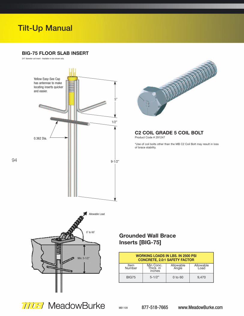
Grounded Wall Brace
Inserts [BIG-75]
Min Conc. Thick. ininches
5-1/2”
WORKING LOADS IN LBS. IN 2500 PSICONCRETE, 2.0:1 SAFETY FACTOR
Allowable Load
9,470
AllowableAngle
0 to 60
ItemNumber
BIG75
BIG-75 FLOOR SLAB INSERT3/4” diameter coil insert - Available in size shown only.
Yellow Easy-See Caphas antennae to makelocating inserts quickerand easier.
0.362 Dia.
1/2”
5”
9-1/2”
C2 COIL GRADE 5 COIL BOLT Product Code # 291247
*Use of coil bolts other than the MB C2 Coil Bolt may result in loss
of brace stability.
Allowable Load
0˚ to 60˚
Min. 5-1/2”
95
www.MeadowBurke.com 877-518-7665 MB1109
Tilt-Up Manual
���
���
���
�� �
!��F
�����
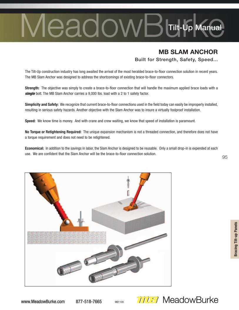
MB SLAM ANCHORBuilt for Strength, Safety, Speed...
The Tilt-Up construction industry has long awaited the arrival of the most heralded brace-to-floor connection solution in recent years.
The MB Slam Anchor was designed to address the shortcomings of existing brace-to-floor connectors.
Strength: The objective was simply to create a brace-to-floor connection that will handle the maximum applied brace loads with a
single bolt. The MB Slam Anchor carries a 9,000 lbs. load with a 2 to 1 safety factor.
Simplicity and Safety: We recognize that current brace-to-floor connections used in the field today can easily be improperly installed,
resulting in serious safety hazards. Another objective with the Slam Anchor was to insure a virtually foolproof installation.
Speed: We know time is money. And with crane and crew waiting, we know that speed of installation is paramount.
No Torque or Retightening Required: The unique expansion mechanism is not a threaded connection, and therefore does not have
a torque requirement and does not need to be retightened.
Economical: In addition to the savings in labor, the Slam Anchor is designed to be reusable. Only a small drop-in is expended at each
use. We are confident that the Slam Anchor will be the brace-to-floor connection solution.
www.MeadowBurke.com 877-518-7665
Tilt-Up Manual
96
877-518-7665 www.MeadowBurke.com MB1109
Tilt-Up Manual
877-518-7665 www.MeadowBurke.com
Tilt-Up Manual
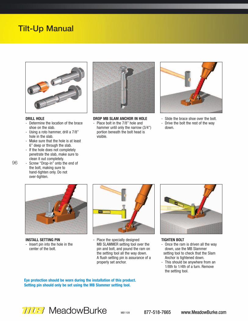
DRILL HOLE- Determine the location of the brace shoe on the slab.
- Using a roto hammer, drill a 7/8” hole in the slab.
- Make sure that the hole is at least 6” deep or through the slab.
- If the hole does not completely penetrate the slab, make sure to clean it out completely.
- Screw “Drop-in” onto the end of the bolt, making sure to hand-tighten only. Do not over-tighten.
DROP MB SLAM ANCHOR IN HOLE- Place bolt in the 7/8” hole and hammer until only the narrow (3/4") portion beneath the bolt head is visible.
- Slide the brace shoe over the bolt.- Drive the bolt the rest of the way down.
INSTALL SETTING PIN- Insert pin into the hole in the center of the bolt.
- Place the specially designed MB SLAMMER setting tool over the pin and bolt, and pound the ram on the setting tool all the way down. A flush setting pin is assurance of a properly set anchor.
TIGHTEN BOLT- Once the ram is driven all the way down, use the MB Slammer setting tool to check that the Slam Anchor is tightened down.
- This should be anywhere from an 1/8th to 1/4th of a turn. Remove the setting tool.
Eye protection should be worn during the installation of this product.
Setting pin should only be set using the MB Slammer setting tool.
97
www.MeadowBurke.com 877-518-7665 MB1109
Tilt-Up Manual
���
���
���
�� �
!��F
�����
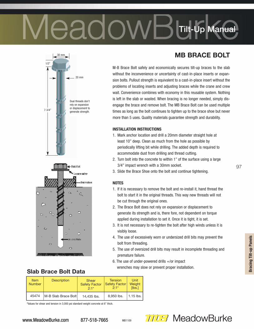
MB BRACE BOLT
M-B Brace Bolt safely and economically secures tilt-up braces to the slab
without the inconvenience or uncertainty of cast-in-place inserts or expan-
sion bolts. Pullout strength is equivalent to a cast-in-place insert without the
problems of locating inserts and adjusting braces while the crane and crew
wait. Convenience combines with economy in this reusable system. Nothing
is left in the slab or wasted. When bracing is no longer needed, simply dis-
engage the brace and remove bolt. The MB Brace Bolt can be used multiple
times as long as the bolt continues to tighten up to the brace shoe but never
more than 5 uses. Quality materials guarantee strength and durability.
INSTALLATION INSTRUCTIONS
1. Mark anchor location and drill a 20mm diameter straight hole at
least 10” deep. Clean as much from the hole as possible by
periodically lifting bit while drilling. The added depth is required to
accommodate dust from drilling and thread cutting.
2. Turn bolt into the concrete to within 1” of the surface using a large
3/4” impact wrench with a 30mm socket.
3. Slide the Brace Shoe onto the bolt and continue tightening.
NOTES
1. If it is necessary to remove the bolt and re-install it, hand thread the
bolt to start it in the original threads. This way new threads will not
be cut through the original ones.
2. The Brace Bolt does not rely on expansion or displacement to
generate its strength and is, there fore, not dependent on torque
applied during installation to set it. Once it is tight, it is set.
3. It is not necessary to re-tighten the bolt after high winds unless it is
visibly loose.
4. The use of excessively worn or undersized drill bits may prevent the
bolt from threading.
5. The use of oversized drill bits may result in incomplete threading and
premature failure.
6. The use of under-powered drills +/or impact
wrenches may slow or prevent proper installation.Slab Brace Bolt Data
ItemNumber
45474
Description
M-B Slab Brace Bolt
ShearSafety Factor
2:1*
14,435 lbs.
TensionSafety Factor
2:1*
8,950 lbs.
UnitWeight[lbs.]
1.15 lbs.
*Values for shear and tension in 3,000 psi standard weight concrete at 6” thick.
Dual threads don’trely on expansionor displacement to generate strength.
20 mm
1/2”
30 mm
7-3/4”
www.MeadowBurke.com 877-518-7665
Tilt-Up Manual
98
877-518-7665 www.MeadowBurke.com MB1109
Tilt-Up Manual
877-518-7665 www.MeadowBurke.com
Tilt-Up Manual
SUPER BOLT
Super Bolt safely and economically secures tilt-up braces to the slab with-
out the inconvenience or uncertainty of cast-in-place inserts or expansion
bolts. Super Bolt penetrates through the slab to engage the concrete at top
and bottom in a vise like grip. Pullout strength is equivalent to a cast-in-
place insert without the problems of locating inserts and adjusting braces
while the crane and crew wait. Convenience combines with economy in
this reusable system.
Nothing is left in the slab or wasted. When bracing is no longer needed,
simply disengage the brace, pry up the wedge and lift out. The entire sys-
tem can be used over and over again. Quality materials guarantee strength
and durability. The bolt section is a high tensile strength steel forging. The
wedge is high strength cast ductile iron. Together they provide consistent
safety and dependability.
INSTALLATION INSTRUCTIONS
1. Mark anchor location on floor and drill a 1-1/4” diameter straight
hole through concrete floor slab.
2. Insert bolt through hole until eccentric head is below bottom of
slab. Rotate until head is opposite brace shoe slot.
3. Insert wedge into hole adjacent to bolt on side of bolt that is
stamped “WEDGE. Align ear on wedge to slot in brace shoe.
4. Drive wedge through hole to where ear contacts concrete, causing
the eccentric head of the bolt to shift under bottom of slab.
5. Slide brace shoe tight against the bolt, assemble the washer and
hand tighten the nut.
6. Using an electric impact wrench and Burke deep well socket, fully
torque tighten the nut eliminating all slack in the assembly. This
ensures proper engagement of the eccentric head on the bolt with
the underside of the concrete floor slab.
Super Bolt Data
ItemNumber
45SBS
45SBL
Description
Minimum/MaximumFloor Thickness
3-1/2” to 7-1/2” Thick
5-1/2” to 11-1/2” Thick
Length
11-5/8”
15-1/2”
UnitWeight[lbs.]
3.2 lbs.
3.3 lbs.
Length
Wedge
Washer
Nut
Nut Lock
99
www.MeadowBurke.com 877-518-7665 MB1109
Tilt-Up Manual
���
���
���
�� �
!��F
�����
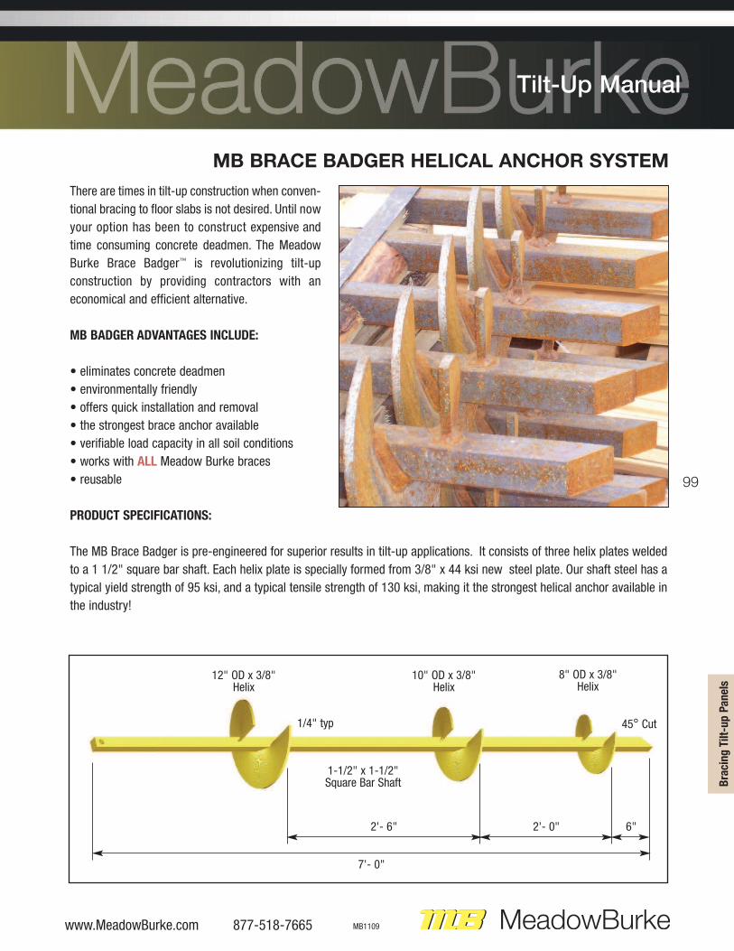
MB BRACE BADGER HELICAL ANCHOR SYSTEM
There are times in tilt-up construction when conven-
tional bracing to floor slabs is not desired. Until now
your option has been to construct expensive and
time consuming concrete deadmen. The Meadow
Burke Brace Badger™ is revolutionizing tilt-up
construction by providing contractors with an
economical and efficient alternative.
C������������D�����AD�B����
• eliminates concrete deadmen
• environmentally friendly
• offers quick installation and removal
• the strongest brace anchor available
• verifiable load capacity in all soil conditions
• works with �BB Meadow Burke braces
• reusable
F�E������F��A�A���AED��
The MB Brace Badger is pre-engineered for superior results in tilt-up applications. It consists of three helix plates welded
to a 1 1/2" square bar shaft. Each helix plate is specially formed from 3/8" x 44 ksi new steel plate. Our shaft steel has a
typical yield strength of 95 ksi, and a typical tensile strength of 130 ksi, making it the strongest helical anchor available in
the industry!
12" OD x 3/8"Helix
1/4" typ
1-1/2" x 1-1/2"Square Bar Shaft
45° Cut
6"2'- 0"2'- 6"
7'- 0"
10" OD x 3/8"Helix
8" OD x 3/8"Helix
100
877-518-7665 www.MeadowBurke.com MB1109
Tilt-Up Manual
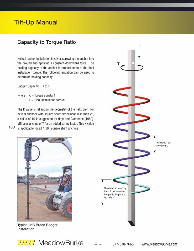
Capacity to Torque Ratio
Helical anchor installation involves screwing the anchor into
the ground and applying a constant downward force. The
holding capacity of the anchor is proportionate to the final
installation torque. The following equation can be used to
determine holding capacity.
Badger Capacity = K x T
where K = Torque constant
T = Final installation torque
The K value is reliant on the geometry of the helix pier. For
helical anchors with square shaft dimensions less than 2",
a value of 10 is suggested by Hoyt and Clemence (1989).
MB uses a value of 7 for an added saftey factor. This K value
is applicable for all 1.50" square shaft anchors.
F
T
Blade pitch per revolution, p
The distance moved bythe hub per revolutionis equal to the pitch, ptypically 3"
Typical MB Brace Badger
Installation
101
www.MeadowBurke.com 877-518-7665 MB1109
Tilt-Up Manual
���
���
���
�� �
!��F
�����
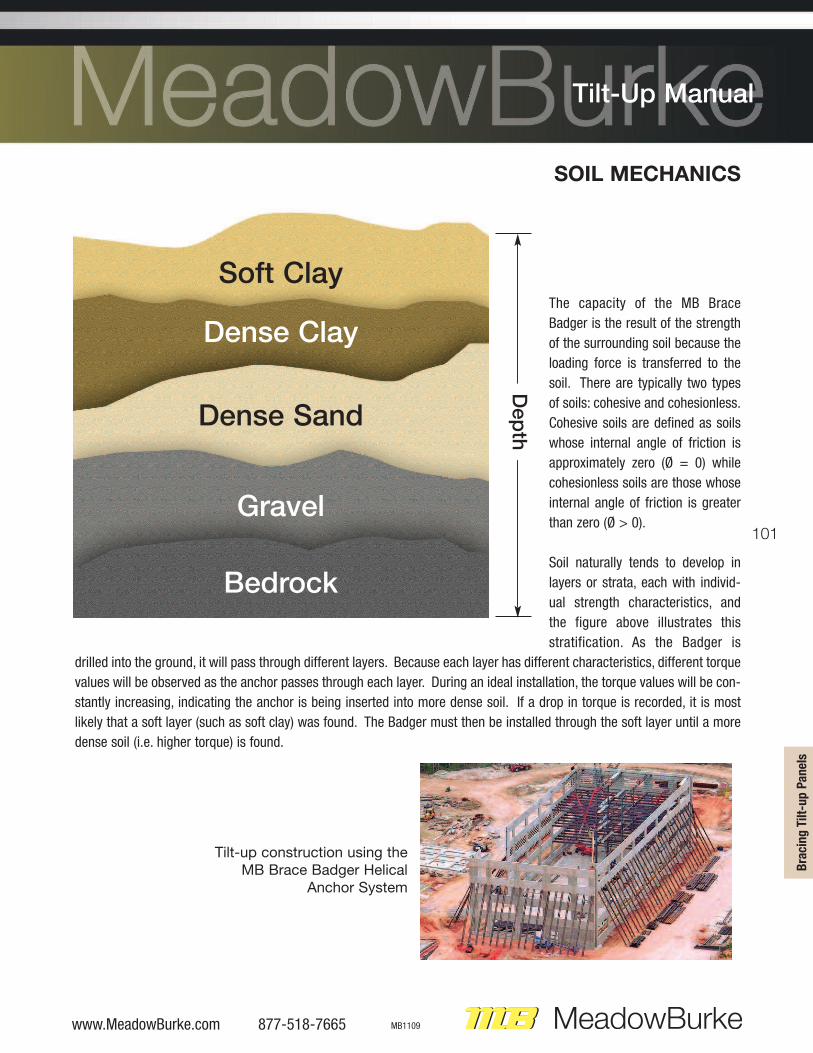
SOIL MECHANICS
The capacity of the MB Brace
Badger is the result of the strength
of the surrounding soil because the
loading force is transferred to the
soil. There are typically two types
of soils: cohesive and cohesionless.
Cohesive soils are defined as soils
whose internal angle of friction is
approximately zero (Ø = 0) while
cohesionless soils are those whose
internal angle of friction is greater
than zero (Ø > 0).
Soil naturally tends to develop in
layers or strata, each with individ-
ual strength characteristics, and
the figure above illustrates this
stratification. As the Badger is
drilled into the ground, it will pass through different layers. Because each layer has different characteristics, different torque
values will be observed as the anchor passes through each layer. During an ideal installation, the torque values will be con-
stantly increasing, indicating the anchor is being inserted into more dense soil. If a drop in torque is recorded, it is most
likely that a soft layer (such as soft clay) was found. The Badger must then be installed through the soft layer until a more
dense soil (i.e. higher torque) is found.
Soft Clay
Dense Sand
Dense Clay
Gravel
Bedrock
Depth
Tilt-up construction using the
MB Brace Badger Helical
Anchor System

102
877-518-7665 www.MeadowBurke.com MB1109
Tilt-Up Manual
Installation
A variety of rotary hydraulic equipment can be used to install the MB Brace
Badger including but not limited to: skidsteers, excavators, and boom mounted
utility trucks.
The installer should maintain a continuous downward pressure on the MB Brace
Badger to avoid auguring during installation.
Throughout the installation of each MB Brace Badger the torque is continuously
monitored and recorded. There is a direct relationship between installation
torque and Badger capacity. Continuous monitoring and recording of torque
throughout installation gives a profile of the soil conditions. Please see page 11
for field installation log.
A 5' extension can be added to install the Badger deeper to reach the stronger soils and the required load capacity. After
the Badger is installed, Badger Connector is bolted to the top of the Badger. The Super Brace shoe is removed and the Doka
rod of the Super Brace is bolted between the ears of the connector. To remove the Badger, simply reverse the hydraulic motor
and back it out of the ground. It is ready for immediate reuse.
Installation Requirements
1) Installation is performed by a MB Brace Badger Systems trained installer.
2) Using a hydraulic drive head, Brace Badgers (Item #580002) are installed to a torque of 2,400 ft-lbs. If the minimum
required torque is not achieved with a single anchor. Please contact Meadow Burke engineering for assistance.
A 5' extensions (Item #580006) may be added until the torque minimum requirement is achieved. It is recommended
that preliminary soil logs at the site be obtained to help predict project requirements. In softer soils with Standard
Penetration Test (SPT) blow counts (N) less than 10, an extension may be required. Installation in rocky soils with blow
counts (N) greater than 30 is not recommended. Also, frozen soils may require pre-auguring so that the anchor can reach
below the frost line.
3) Maximum allowable installation torque is 7,000 ft-lbs.
4) Records of required installation torque for each Badger is required. Please see page 11 for field installation log.
5) Badgers to be installed in-line with the axis of the brace (+/- 5º).
6) Welding, cutting, or any modification of the Badger or its components is prohibited.
7) MB Badger Connector (item #580004) must be used for brace connection. To connect to brace, remove brace shoe and
reuse 5/8" bolt for connector. Connector to Badger requires one 3/4"Ø x 3 1/2" grade 5 bolt.
�������DE���1) The contractor shall locate all the subsurface structures and utilities. Any subsurface structure or utility in the vicinity of the Badger locations shall be clearly marked.
Horizontal Clearance of anchor from any subsurface structure or utility shall be no less than 5'-0" at the depth of the utility. Installation of Badgers underneath utilities or subsurface structures is strictly prohibited.
2) Do not use damaged or worn Brace Badgers. Failure to inspect and replace damaged anchors may result in anchor failure.3) The contractor is to undergo preventive measures to mitigate soil erosion adjacent to installed anchors.4) Any changes resulting from actual installation conditions of the Badger requires that the contractor contact Meadow Burke Engineering for further assistance to deter
mine adequacy of anchor system.
103
www.MeadowBurke.com 877-518-7665 MB1109
Tilt-Up Manual
���
���
���
�� �
!��F
�����
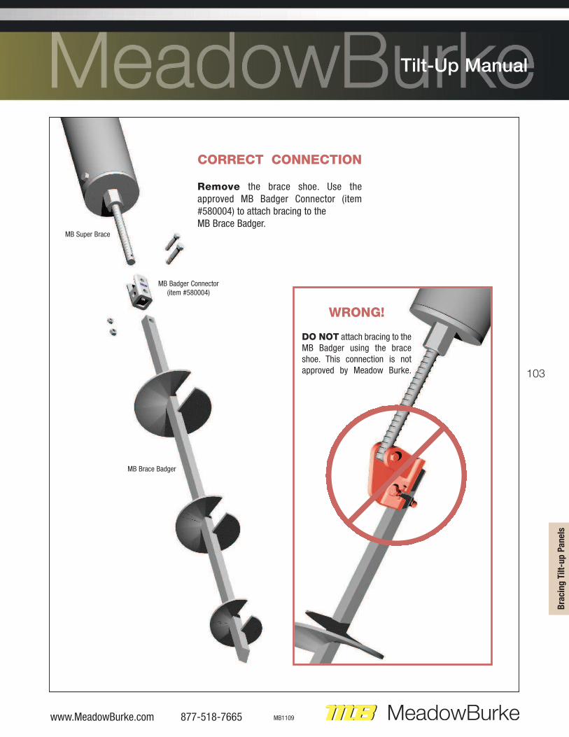
WRONG!
DO NOT attach bracing to theMB Badger using the braceshoe. This connection is notapproved by Meadow Burke.
CORRECT CONNECTION
Remove the brace shoe. Use theapproved MB Badger Connector (item#580004) to attach bracing to the MB Brace Badger.
MB Badger Connector(item #580004)
MB Brace Badger
MB Super Brace
104
877-518-7665 www.MeadowBurke.com MB1109
Tilt-Up Manual
NOTES