mb form cover 09 - meadow burke
TRANSCRIPT

MeadowBurke®
Forming Technical Manual

35 –
44
1 –
1469
– 8
215
– 2
021
– 2
829
– 3
445
– 5
253
– 6
263
– 6
883
– 8
889
– 9
1
3
MeadowBurke®Forming Technical Manual
www.MeadowBurke.com
MB1018
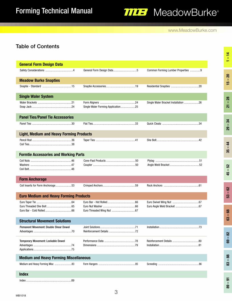
Safety Considerations ......................................4 General Form Design Data................................5 Common Forming Lumber Properties ..............9
Snaptie - Standard ........................................15 Snaptie Accessories........................................19 Residential Snapties ......................................20
Waler Brackets ..............................................21 Snap Jack ......................................................24
Form Aligners ................................................24 Single Waler Forming Application....................25
Single Waler Bracket Installation ....................26
Panel Ties ......................................................30 Flat Ties..........................................................33 Quick Cleats ..................................................34
General Form Design Data
Meadow Burke Snapties
Single Waler System
Panel Ties/Panel Tie Accessories
Coil Inserts for Form Anchorage......................53 Crimped Anchors ............................................59 Rock Anchors ................................................61
Form Anchorage
Medium and Heavy Forming Misc ..........................83 Form Hangers ........................................................85 Screeding ..............................................................86
Medium and Heavy Forming Miscellaneous
Pencil Rod ......................................................36 Coil Ties..........................................................38
Taper Ties ......................................................41
She Bolt..........................................................42
Coil Nuts ........................................................46 Washers ........................................................47 Coil Bolt..........................................................48
Cone-Fast Products ........................................50 Coupler ..........................................................50
Plylag ............................................................51 Angle Weld Bracket ........................................52
Light, Medium and Heavy Forming Products
Euro Taper Tie ................................................64 Euro Threaded She Bolt ..................................65 Euro Bar - Cold Rolled ....................................66
Euro Bar - Hot Rolled......................................66 Euro Nut Washer ............................................66 Euro Threaded Wing Nut ................................67
Euro Swivel Wing Nut ....................................67 Euro Angle Weld Bracket ................................67
Euro Medium and Heavy Forming Products
Pemanent Movement: Double Shear Dowel Advantages ....................................................70
Joint Solutions................................................71 Reinforcement Details ....................................72
Installation......................................................73
Structural Movement Solutions
Temporary Movement: Lockable Dowel Advantages ....................................................74 Applications....................................................75
Performance Data ..........................................78 Dimensions ....................................................79
Reinforcement Details ....................................80 Installation......................................................81
Formtie Accessories and Working Parts
Index ..............................................................89
Index
Table of Contents

MeadowBurke®Forming Technical Manual
www.MeadowBurke.com
MB10184
raTed LoadS
It is apparent from the Table that the safety factor applied to a given product
is a variable depending on the degree of hazard involved in the application of
the product. The user of the products in this publication must determine the
applicable safety factor for the products as a function of its use as described
in the Table.
Product load ratings are based on the ultimate strength of the metal. Safe
working loads displayed in this publication are approximate minimum values.
Due to the variety of applications, the responsibility of selecting appropriate
safety factors is up to the user of the product. Any recalculation of safe work-
ing loads due to a change in the approximate minimum safety factor should
include a careful analysis of all hardware used in the application and the antic-
ipated concrete strength involved. If any doubt, contact a Meadow Burke
Service Center for clarification.
ProdUCT LiaBiLiTy
Meadow Burke stresses that the products in this publication are to be used by
experienced workers with competent supervision. If an end user does not have
qualified and experienced workers or installers, or does not have the technical
expertise in the application of the product or does not know the consequences
from improper use of the product; do not use the product without consulting a
Meadow Burke Service Center.
Worn WorKinG ParTS
It is the responsibility of the user to continually inspect working parts and
hardware for wear. If wear is present, the product should be discarded. Do not
attempt to straighten bent bolts; they should be scrapped. Discard any bolts
known to have been used at loads of 70% or more of ultimate capacity.
WeLdinG
Since it is impossible to control field conditions, Meadow Burke does not guar-
antee any product that has been altered in any way after
leaving its factory of origin. This includes any type of welding or
bending. Do not weld any Meadow Burke product without the
assurance from a qualified engineer that the weld is in a non-critical area.
Welding can cause embrittlement at the load point and greatly reduce load car-
rying capacity.
CAUTIO N: It is extremely important for the user of Meadow Burke
products to evaluate product applications, determine the appropriate mini-
mum safe working loads and control all field conditions to prevent loads in
excess of the determined minimum safe working loads.
WARNING: Improper application or faulty installation of any product
displayed in this publication can cause hazardous conditions that can result in
serious injury or death.
Meadow Burke recommends that provisions outlined in the American Concrete Institute publication, “Recommended Practice for Concrete Formwork” (ACI 347),
be strictly adhered to by all persons and organizations working in the concrete construction industry. Meadow Burke also strongly advises that the safety factors
shown in the Minimum Safety Factors of Formwork Accessories Table be followed. If there are any unusual job site conditions, such as shock, impact, vibration,
etc., safety factors must be increased to ensure worker protection.
MiniMUM SafeTy faCTorS of forMWorK aCCeSSorieS
accessory Safety factor Type of ConstuctionForm Tie
Form Hangers Form Anchor Form Anchor
Insert Used as Form Tie
2:1 2:1 2:1 3:1
2:1
All formwork Supporting form, concrete weight and live loads
Supporting form weight and concrete pressure only Supporting form weight, concrete pressure, live loads and impact
Precast concrete panels used as formwork Heavy cantilever formwork
SafeTy ConSideraTion

MeadowBurke®Forming Technical Manual
www.MeadowBurke.com
MB1018
ProdUCT deSiGn
Meadow Burke reserves the right to change product designs and/or
product safe load ratings at any time without prior notice.
faCTorS affeCTinG LaTeraL PreSSUre on
forMWorK
WeiGHT of ConCreTe
The weight of concrete is a direct influence since hydrostatic pressure at any
point in a fluid is created by the weight of the superimposed fluid. Liquid
(hydrostatic) pressure is the same in all directions at a given depth in the fluid
and acts at right angles to any surface that confines it. If
concrete acted as a true liquid, the pressure would be equal to the
density of fluid times the depth, to the point at which the pressure was being
considered. However, concrete is a mixture of solids and water whose
behavior only approximates that of liquid for a limited time.
raTe of PLaCeMenT
The average rate of rise of the concrete in the form is referred to as the rate
of placement. The rate of placement has a primary effect on lateral pressure
and the maximum lateral pressure is proportional to the rate of placement, up
to a limit equal to the full fluid pressure. As the concrete
is being placed, the lateral pressure at a given point increases as the
concrete depth above the point increases. Finally, by consolidation and/or
stiffening, the concrete will support itself and will no longer cause lateral pres-
sure on the form.
ConCreTe ViBraTion
Internal vibration is a primary method of consolidating concrete in the form. It
results in temporary, local lateral pressures that are 10 to 20
percent greater than those caused by simple spading. Since internal vibrating
is an accepted common practice, forms should be designed to handle the
added pressures.
Revibration and external vibration are other types of vibration used in
certain types of construction. Revibration and external vibration methods pro-
duce higher lateral loads than the internal vibration process and require spe-
cially designed forms. External vibration (also referred to as form vibration) is
accomplished by attaching vibrators to the outside of the form. The form itself
is vibrated to hammer the form against the concrete. The frequency/ampli-
tude of external vibration must be regulated to consolidate the concrete but
not too strong to damage the form. Revibration is the process where a vibra-
tor is forced down through the upper placement into layers of concrete that
have stiffened or have nearly reached initial set. Localized lateral pressures,
up to 300 psf/ft of head of concrete, have been recorded using vigorous revi-
bration. Neither revibration nor external vibrations have been sufficiently
investigated to be expressed in a standard formula. Pressure formulae in this
publication are limited to concrete vibrated internally at the time of placement.
5
1 –
14
GeneraL forM deSiGn daTa

LaTeraL PreSSUre VaLUeS for forM deSiGn
VerTiCaL WaLL forMS
The American Concrete Institute Committee 347-04 (Chapter 2) has developed the formulas below for maximum lateral pressure on the form,
prescribed temperatures, rate of placement, vibration, concrete weight and slump. They are working formulas based on available data and are
recommended for form design. No claim is made for their theoretical precision.
Walls with Rate of Placement (R) not exceeding 7 ft/hr and wall height not exceeding 14 ft and columns:
p = (150 + 9,000R/T) CcCw ..................................................2.1
Maximum = wxh
Minimum = 600Cwpsf
Walls with Rate of Placement (R) not exceeding 7 ft/hr and wall heights exceeding 14 ft, and for
all walls with a placement rate of 7 to 15 ft/hr:
p = CwCc (150 + 43,400/T + 2,800R/T) ...............................2.2
Maximum = wxh
Minimum = 600Cwpsf
Where:
p = maximum lateral pressure (psf)
R = rate of placement (ft/hr)
T = temperature of the concrete
h = maximum height of fresh concrete
w = unit weight of concrete (pcf)
Cw = unit weight coefficient, 1.0 for w = 150 pcf
Cc = chemistry coefficient
6
MeadowBurke®Forming Technical Manual
www.MeadowBurke.com
MB1018
ConCreTe TeMPeraTUre
The temperature of the concrete at the time of placement has an important
influence on pressure due to the affect it has on the setting time of the con-
crete. At lower concrete temperatures, the concrete takes longer to stiffen, so
a greater depth of concrete can be placed before it becomes firm enough to
be self-supporting. The greater liquid head results in higher lateral pressures.
This is an important form design consideration when anticipating concrete
placement in cold weather, with fly ash replacement or when using retarding
admixtures.
oTHer VariaBLeS
There are numerous other variables that will affect the lateral pressure in the
form. Such things as the consistency of the concrete, the amount and location
of reinforcing steel, ambient temperature, pore water pressure, aggregate
size, placing procedures, type of cement, depth of placement, cross-section of
the form, smoothness of the form faces and permeability of the form can all
have an effect on the lateral pressure in the form. However, under normal con-
ditions and forming practices, the range of these variable effects is generally
small and is usually neglected.
On the other hand, the use of fly ash or other pozzolan as a cement
replacement at low ambient temperatures or with a retarding mixture can
have a significant effect on lateral pressure. Likewise, superplasticizing
admixtures and the retarders themselves can have a substantial effect on the
lateral pressure. These conditions must be given due consideration during the
form design process.
The formulae are applicable for internally vibrated structural concrete of nor-
mal weight and density, produced with Type I cement and containing no poz-
zolans or admixtures and with a slump of less than four inches. Good con-
crete placing procedures are assumed; for example, vibration is used for con-
solidation only and is limited to four (4) feet below the surface of the concrete.
The formulae assume that concrete “set” will occur as expected, usually in one
hour. Do not use design pressures in excess of w x h.
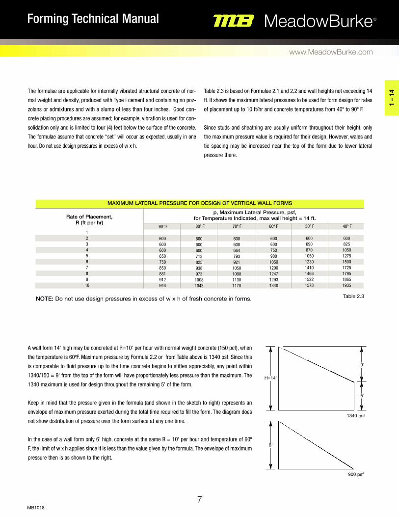
Table 2.3 is based on Formulae 2.1 and 2.2 and wall heights not exceeding 14
ft. It shows the maximum lateral pressures to be used for form design for rates
of placement up to 10 ft/hr and concrete temperatures from 40º to 90º F.
Since studs and sheathing are usually uniform throughout their height, only
the maximum pressure value is required for their design. However, wales and
tie spacing may be increased near the top of the form due to lower lateral
pressure there.
A wall form 14' high may be concreted at R=10' per hour with normal weight concrete (150 pcf), when
the temperature is 60ºF. Maximum pressure by Formula 2.2 or from Table above is 1340 psf. Since this
is comparable to fluid pressure up to the time concrete begins to stiffen appreciably, any point within
1340/150 = 9' from the top of the form will have proportionately less pressure than the maximum. The
1340 maximum is used for design throughout the remaining 5' of the form.
Keep in mind that the pressure given in the formula (and shown in the sketch to right) represents an
envelope of maximum pressure exerted during the total time required to fill the form. The diagram does
not show distribution of pressure over the form surface at any one time.
In the case of a wall form only 6' high, concrete at the same R = 10' per hour and temperature of 60º
F, the limit of w x h applies since it is less than the value given by the formula. The envelope of maximum
pressure then is as shown to the right.
noTe: Do not use design pressures in excess of w x h of fresh concrete in forms.
7
MeadowBurke®Forming Technical Manual
www.MeadowBurke.com
MB1018
1 –
14
1 2 3 4 5 6 7 8 9
10
600 600 600 650 750 850 881 912 943
MaXiMUM LaTeraL PreSSUre for deSiGn of VerTiCaL WaLL forMS
rate of Placement, r (ft per hr)
p, Maximum Lateral Pressure, psf, for Temperature indicated, max wall height = 14 ft.
600 600 600 713 825 938 973 1008 1043
600 600 664 793 921 1050 1090 1130 1170
90º F 80º F 70º F 60º F 50º F 40º F
600 600 750 900 1050 1200 1247 1293 1340
600 690 870
1050 1230 1410 1466 1522 1578
600 825 1050 1275 1500 1725 1795 1865 1935
9'
H=14'
5'
1340 psf
6'
900 psf
Table 2.3
8
MeadowBurke®Forming Technical Manual
www.MeadowBurke.com
MB1018
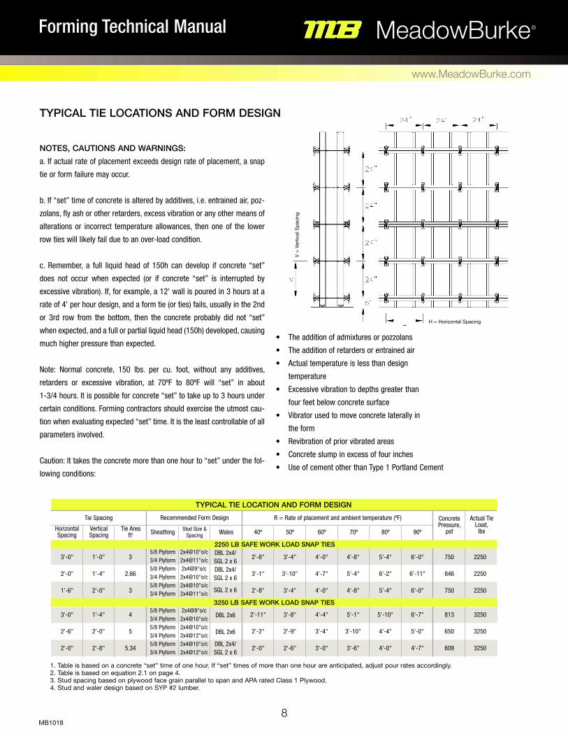
noTeS, CaUTionS and WarninGS:
a. If actual rate of placement exceeds design rate of placement, a snap
tie or form failure may occur.
b. If “set” time of concrete is altered by additives, i.e. entrained air, poz-
zolans, fly ash or other retarders, excess vibration or any other means of
alterations or incorrect temperature allowances, then one of the lower
row ties will likely fail due to an over-load condition.
c. Remember, a full liquid head of 150h can develop if concrete “set”
does not occur when expected (or if concrete “set” is interrupted by
excessive vibration). If, for example, a 12' wall is poured in 3 hours at a
rate of 4' per hour design, and a form tie (or ties) fails, usually in the 2nd
or 3rd row from the bottom, then the concrete probably did not “set”
when expected, and a full or partial liquid head (150h) developed, causing
much higher pressure than expected.
Note: Normal concrete, 150 lbs. per cu. foot, without any additives,
retarders or excessive vibration, at 70ºF to 80ºF will “set” in about
1-3/4 hours. It is possible for concrete “set” to take up to 3 hours under
certain conditions. Forming contractors should exercise the utmost cau-
tion when evaluating expected “set” time. It is the least controllable of all
parameters involved.
Caution: It takes the concrete more than one hour to “set” under the fol-
lowing conditions:
• The addition of admixtures or pozzolans
• The addition of retarders or entrained air
• Actual temperature is less than design
temperature
• Excessive vibration to depths greater than
four feet below concrete surface
• Vibrator used to move concrete laterally in
the form
• Revibration of prior vibrated areas
• Concrete slump in excess of four inches
• Use of cement other than Type 1 Portland Cement
TyPiCaL Tie LoCaTion and forM deSiGnR = Rate of placement and ambient temperature (ºF) Concrete
Pressure, psf
Actual Tie Load,
lbs90º80º70º60º50º40º
Recommended Form DesignTie Spacing
WalesStud Size & SpacingSheathingTie Area
ft2Vertical Spacing
Horizontal Spacing
3'-0"
2'-0"
1'-6"
3'-0"
2'-6"
2'-0"
1'-0"
1'-4"
2'-0"
1'-4"
2'-0"
2'-8"
3
2.66
3
4
5
5.34
DBL 2x4/ SGL 2 x 6 DBL 2x4/ SGL 2 x 6
SGL 2 x 6
DBL 2x6
DBL 2x6 DBL 2x4/
SGL 2 x 6
2'-8"
3'-1"
2'-8"
2'-11"
2'-2"
2'-0"
3'-4"
3'-10"
3'-4"
3'-8"
2'-9"
2'-6"
4'-0"
4'-7"
4'-0"
4'-4"
3'-4"
3'-0"
4'-8"
5'-4"
4'-8"
5'-1"
3'-10"
3'-6"
5'-4"
6'-2"
5'-4"
5'-10"
4'-4"
4'-0"
6'-0"
6'-11"
6'-0"
6'-7"
5'-0"
4'-7"
750
846
750
813
650
609
2250
2250
2250
3250
3250
3250
5/8 Plyform 3/4 Plyform 5/8 Plyform 3/4 Plyform 5/8 Plyform 3/4 Plyform
5/8 Plyform 3/4 Plyform 5/8 Plyform 3/4 Plyform 5/8 Plyform 3/4 Plyform
2x4@10"o/c 2x4@11"o/c 2x4@9"o/c 2x4@10"o/c 2x4@10"o/c 2x4@11"o/c
2x4@9"o/c 2x4@10"o/c 2x4@10"o/c 2x4@12"o/c 2x4@10"o/c 2x4@12"o/c
1. Table is based on a concrete “set” time of one hour. If “set” times of more than one hour are anticipated, adjust pour rates accordingly. 2. Table is based on equation 2.1 on page 4. 3. Stud spacing based on plywood face grain parallel to span and APA rated Class 1 Plywood. 4. Stud and waler design based on SYP #2 lumber.
TyPiCaL Tie LoCaTionS and forM deSiGn
V =
Vert
ical
Spa
cing
H = Horizontal Spacing
2250 LB Safe WorK Load SnaP TieS
3250 LB Safe WorK Load SnaP TieS
9
MeadowBurke®Forming Technical Manual
www.MeadowBurke.com
MB1018
1 –
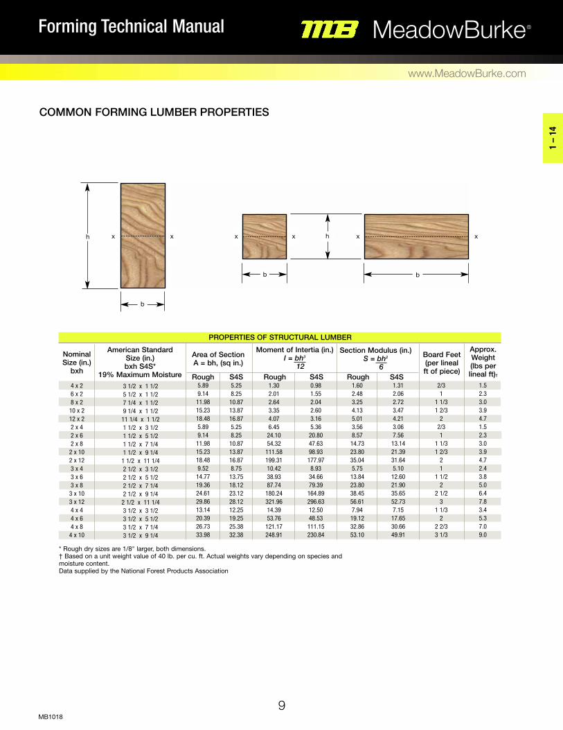
14* Rough dry sizes are 1/8" larger, both dimensions. † Based on a unit weight value of 40 lb. per cu. ft. Actual weights vary depending on species and moisture content. Data supplied by the National Forest Products Association
CoMMon forMinG LUMBer ProPerTieS
3 1/2 x 1 1/2 5 1/2 x 1 1/2 7 1/4 x 1 1/2 9 1/4 x 1 1/2
11 1/4 x 1 1/2 1 1/2 x 3 1/2 1 1/2 x 5 1/2 1 1/2 x 7 1/4 1 1/2 x 9 1/4
1 1/2 x 11 1/4 2 1/2 x 3 1/2 2 1/2 x 5 1/2 2 1/2 x 7 1/4 2 1/2 x 9 1/4
2 1/2 x 11 1/4 3 1/2 x 3 1/2 3 1/2 x 5 1/2 3 1/2 x 7 1/4 3 1/2 x 9 1/4
ProPerTieS of STrUCTUraL LUMBer
american Standard Size (in.) bxh S4S*
19% Maximum Moisture
area of Section a = bh, (sq in.)
2/3 1
1 1/3 1 2/3
2 2/3 1
1 1/3 1 2/3
2 1
1 1/2 2
2 1/2 3
1 1/3 2
2 2/3 3 1/3
nominal Size (in.)
bxh
4 x 2 6 x 2 8 x 2
10 x 2 12 x 2 2 x 4 2 x 6 2 x 8
2 x 10 2 x 12 3 x 4 3 x 6 3 x 8
3 x 10 3 x 12 4 x 4 4 x 6 4 x 8
4 x 10
5.89 9.14
11.98 15.23 18.48 5.89 9.14
11.98 15.23 18.48 9.52
14.77 19.36 24.61 29.86 13.14 20.39 26.73 33.98
5.25 8.25 10.87 13.87 16.87 5.25 8.25 10.87 13.87 16.87 8.75 13.75 18.12 23.12 28.12 12.25 19.25 25.38 32.38
1.30 2.01 2.64 3.35 4.07 6.45
24.10 54.32 111.58 199.31 10.42 38.93 87.74 180.24 321.96 14.39 53.76 121.17 248.91
approx. Weight (lbs per lineal ft)†
Board feet (per lineal ft of piece)
rough S4S
Moment of intertia (in.) I = bh3 12
Section Modulus (in.) S = bh2
6
0.98 1.55 2.04 2.60 3.16 5.36 20.80 47.63 98.93 177.97 8.93 34.66 79.39 164.89 296.63 12.50 48.53 111.15 230.84
1.60 2.48 3.25 4.13 5.01 3.56 8.57 14.73 23.80 35.04 5.75 13.84 23.80 38.45 56.61 7.94 19.12 32.86 53.10
1.31 2.06 2.72 3.47 4.21 3.06 7.56 13.14 21.39 31.64 5.10 12.60 21.90 35.65 52.73 7.15 17.65 30.66 49.91
1.5 2.3 3.0 3.9 4.7 1.5 2.3 3.0 3.9 4.7 2.4 3.8 5.0 6.4 7.8 3.4 5.3 7.0 9.0
rough S4S S4Srough
h
b
x x x x x x
b b
h

10
MeadowBurke®Forming Technical Manual
www.MeadowBurke.com
MB1018
Safe Spacing ( l ) in Inches of Supports for Plywood Sheathing Continuous Over Four or More Supports ∅max = l/360, but not to exceed 1/16"
Sanded thickness, panel grain parallel to span
Pressure or Load
(lbs per sq ft) Sanded Thickness, face Grain Perpendicular to SpanSanded Thickness, face Grain Parallel to SpanfS = 72 psi fb = 1930 psi ee = 1500000 psi e = 1650000 psi
1/2 in. 5/8 in. 3/4 in. 1 in. 1/2 in. 5/8 in. 3/4 in. 1 in.31 29 27 26 25 24 21 20 18 16 15 14 13 13
24 22 21 20 19 18 15 13 12 11 10 10 9 8
26 24 23 22 21 20 18 15 14 13 12 11 10 10
21 19 18 17 15 15 13 12 11 10 9 8 8 7
75 100 125 150 175 200 300 400 500 600 700 800 900
1000
14 13 12 11 10 10 8 7 7 6 5 4 4 3
16 14 13 12 11 11 9 8 7 7 6 5 4 4
21 19 19 17 15 15 12 11 10 9 8 7 6 5
28 26 24 23 22 21 19 17 14 13 12 11 11 10
TaBLe BaSed on aPa raTed PLyWood CLaSS 1
forM LoadinG in PoUndS/SQ. fooT for inCreMenTaL SLaB THiCKneSS*
*Values above include 50 psf live load for construction loads. Formwork dead load is not included.
100 115 125 135 150
Concrete Weight
(lbs per sq ft)
Slab Thickness
6 in. 8 in. 10 in. 12 in. 14 in. 16 in.4 in.2 in.67 70 71 73 75
84 89 92 95
100
100 108 113 118 125
117 127 134 140 150
134 146 155 163 175
150 165 175 185 200
167 185 196 208 225
184 204 217 230 250
forM LoadinG daTa
SpacingSpacing
Spacing
Sanded thickness, panel grain perpendicular to span.
SpacingSpacing
Spacing

Spacing
Safe Spacing ( l ) in Inches of Supports for Joists, Studs, etc. Single Span
11
MeadowBurke®Forming Technical Manual
www.MeadowBurke.com
MB1018
1 –
14
equivalent Uniform Load (lbs per lineal ft)
nominal Size of S4S Lumber
fb (psi) =
e = 1,600,000 psi
2 x 4 2 x 6 2 x 8 2 x 10 3 x 6 4 x 4 4 x 8 2 x 12
∅max = l/360, but not to exceed 1/4"
SiMPLe SPanSiMPLe SPan SinGLe-PLy WaLeS
975 156 131 118 103 92 84 78 73 69 65 62 59 57 55 53 51 50 48 47 46 45 44 43 42 41 40 39 39 38 37
1050 135 113 102 88 79 72 66 62 58 55 53 51 49 47 45 44 42 41 40 39 38 37 36 36 35 34 34 33 32 32
1200 112 94 78 68 61 55 51 48 45 43 41 39 37 36 35 34 33 32 31 30 29 29 28 27 27 26 26 25 25 24
1250 91 73 61 52 47 43 39 37 35 33 31 30 29 28 27 26 25 24 24 23 23 22 22 21 21 20 20 19 19 19
1500 58 46 40 36 32 30 27 26 24 23 22 21 20 19 19 18 17 17 16 16 16 15 15 15 14 14 14 13 13 13
100 200 300 400 500 600 700 800 900
1000 1100 1200 1300 1400 1500 1600 1700 1800 1900 2000 2100 2200 2300 2400 2500 2600 2700 2800 2900 3000
1250 104 86 75 68 61 55 51 48 45 43 41 39 37 36 35 34 33 32 31 30 29 29 28 27 27 26 26 25 25 24
1500 77 61 54 49 45 43 40 39 37 35 33 32 31 30 29 28 27 26 25 25 24 24 23 22 22 22 21 21 20 20
1200 139 117 105 98 93 85 78 73 69 65 62 60 57 55 53 52 50 49 47 46 45 44 43 42 41 40 40 39 38 38
1. All values based on 2005 NDS for S.Y.P. #2 Cd = 1.45, CM_b = 0.85 (1.0 for 2 x 10 & 2 x 12), CM_V = 0.97, CM_e = 0.9 2. Multi-spans continuous over 3 spans or 4 supports. 3. ∅max = l/360, does not to exceed 1/4" 4. All values based on worst case of deflection, bending or shear. 5. All values above bold line are controlled by deflection. Bending and shear govern below.

12
MeadowBurke®Forming Technical Manual
www.MeadowBurke.com
MB1018
∅max = l/360, but not to exceed 1/4"Spacing
Spacing
SpacingSafe Spacing ( l ) in Inches of Supports for Joists, Studs, etc. Continuous Over Three or More Supports
equivalent Uniform Load (lbs per lineal ft)
nominal Size of S4S Lumber
fb (psi) =
e = 1,600,000 psi
2 x 4 2 x 6 2 x 8 2 x 10 3 x 6 4 x 4 4 x 8 2 x 12
MULTi-SPan SinGLe-PLy WaLeS
975 183 154 133 115 103 94 87 81 77 73 69 66 64 61 59 57 56 54 53 51 50 49 47 45 44 43 42 40 39 38
1050 158 133 114 98 88 80 74 69 65 62 59 57 54 52 51 49 47 46 45 43 41 40 38 37 36 35 34 33 32 32
1200 131 107 88 76 68 62 57 53 50 48 46 44 42 40 39 38 37 35 35 34 32 31 30 29 28 27 27 26 25 25
1250 107 83 68 59 52 48 44 41 39 37 35 34 32 31 30 29 28 27 26 25 24 23 23 22 21 21 20 20 19 19
1500 72 57 47 41 36 33 31 29 27 26 24 23 22 21 20 19 18 17 17 16 15 15 14 14 13 13 13 12 12 12
100 200 300 400 500 600 700 800 900
1000 1100 1200 1300 1400 1500 1600 1700 1800 1900 2000 2100 2200 2300 2400 2500 2600 2700 2800 2900 3000
1250 121 102 88 76 68 62 57 53 50 48 46 44 42 40 39 38 37 35 35 34 33 32 31 31 30 29 29 28 28 27
1500 94 76 66 60 56 51 47 44 41 39 37 36 34 33 32 31 30 29 28 28 27 26 26 25 25 24 24 23 23 22
1200 163 137 123 115 104 95 88 82 77 73 70 67 64 62 60 58 56 54 53 52 50 49 48 47 46 45 44 44 43 42
MULTi-SPan SinGLe WaLeS ConTinoUS oVer 3-SPanS or 4 SUPPorTS
1. All values based on 2005 NDS for S.Y.P. #2 Cd = 1.45, CM_b = 0.85 (1.0 for 2 x 10 & 2 x 12), CM_V = 0.97, CM_e = 0.9 2. Multi-spans continuous over 3 spans or 4 supports. 3. ∅max = l/360, does not to exceed 1/4" 4. All values based on worst case of deflection, bending or shear. 5. All values above bold line are controlled by deflection. Bending and shear govern below.
13
MeadowBurke®Forming Technical Manual
www.MeadowBurke.com
MB1018
1 –
14
Spacing
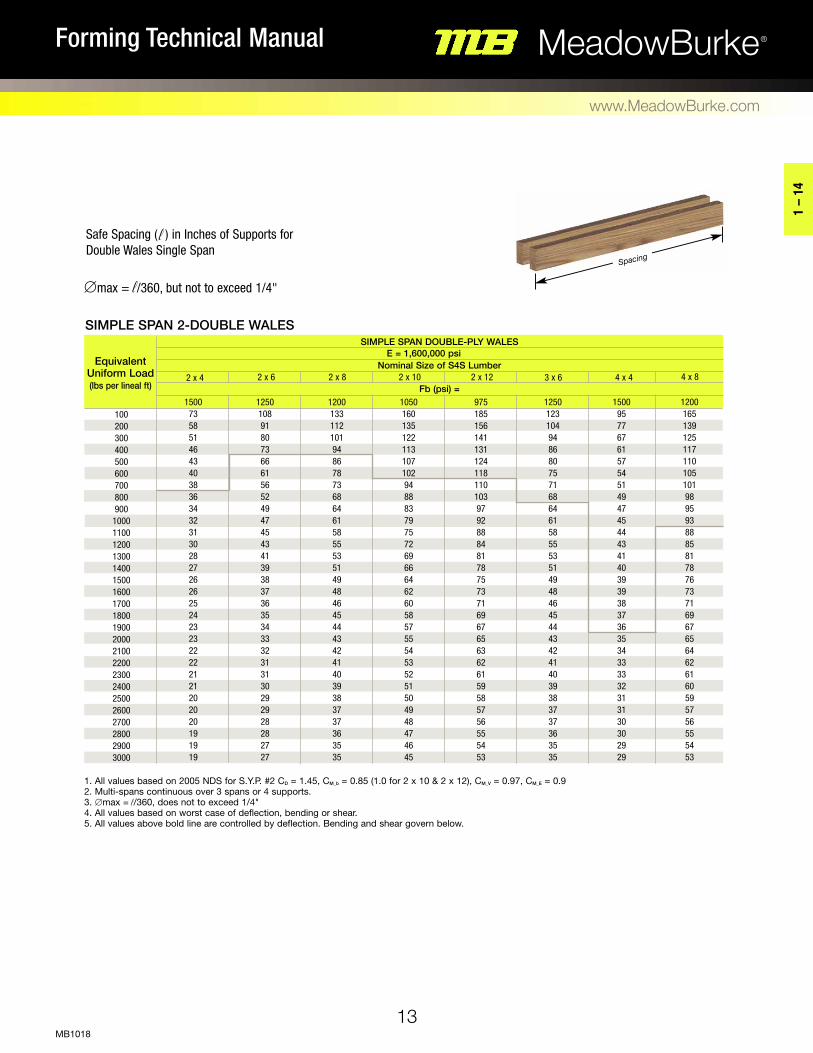
Safe Spacing ( l ) in Inches of Supports for Double Wales Single Span
∅max = l/360, but not to exceed 1/4"
equivalent Uniform Load (lbs per lineal ft)
nominal Size of S4S Lumber
fb (psi) =
e = 1,600,000 psi
2 x 4 2 x 6 2 x 8 2 x 10 3 x 6 4 x 4 4 x 8 2 x 12
SiMPLe SPan doUBLe-PLy WaLeS
975 185 156 141 131 124 118 110 103 97 92 88 84 81 78 75 73 71 69 67 65 63 62 61 59 58 57 56 55 54 53
1050 160 135 122 113 107 102 94 88 83 79 75 72 69 66 64 62 60 58 57 55 54 53 52 51 50 49 48 47 46 45
1200 133 112 101 94 86 78 73 68 64 61 58 55 53 51 49 48 46 45 44 43 42 41 40 39 38 37 37 36 35 35
1250 108 91 80 73 66 61 56 52 49 47 45 43 41 39 38 37 36 35 34 33 32 31 31 30 29 29 28 28 27 27
1500 73 58 51 46 43 40 38 36 34 32 31 30 28 27 26 26 25 24 23 23 22 22 21 21 20 20 20 19 19 19
100 200 300 400 500 600 700 800 900
1000 1100 1200 1300 1400 1500 1600 1700 1800 1900 2000 2100 2200 2300 2400 2500 2600 2700 2800 2900 3000
1250 123 104 94 86 80 75 71 68 64 61 58 55 53 51 49 48 46 45 44 43 42 41 40 39 38 37 37 36 35 35
1500 95 77 67 61 57 54 51 49 47 45 44 43 41 40 39 39 38 37 36 35 34 33 33 32 31 31 30 30 29 29
1200 165 139 125 117 110 105 101 98 95 93 88 85 81 78 76 73 71 69 67 65 64 62 61 60 59 57 56 55 54 53
SiMPLe SPan 2-doUBLe WaLeS
1. All values based on 2005 NDS for S.Y.P. #2 Cd = 1.45, CM_b = 0.85 (1.0 for 2 x 10 & 2 x 12), CM_V = 0.97, CM_e = 0.9 2. Multi-spans continuous over 3 spans or 4 supports. 3. ∅max = l/360, does not to exceed 1/4" 4. All values based on worst case of deflection, bending or shear. 5. All values above bold line are controlled by deflection. Bending and shear govern below.

14
MeadowBurke®Forming Technical Manual
www.MeadowBurke.com
MB1018
Safe Spacing ( l ) in Inches of Supports for Double Wales Continuous Over Three or More Spans
∅max = l/360, but not to exceed 1/4"
Spacing
Spacing
Spacing
nominal Size of S4S Lumber
fb (psi) =
e = 1,600,000 psi
2 x 4 2 x 6 2 x 8 2 x 10 3 x 6 4 x 4 4 x 8 2 x 12
MULTi-SPan doUBLe-PLy WaLeS
975 217 183 165 154 145 133 123 115 109 103 98 94 90 87 84 81 79 77 75 73 71 69 68 66 65 64 63 61 60 59
1050 188 158 143 133 125 114 105 98 93 88 84 80 77 74 72 69 67 65 64 62 61 59 58 57 55 54 53 52 51 51
1200 156 131 119 107 96 88 81 76 71 68 65 62 59 57 55 53 52 50 49 48 47 46 45 44 43 42 41 40 40 39
1250 127 107 96 83 74 68 63 59 55 52 50 48 46 44 43 41 40 39 38 37 36 35 34 34 33 32 32 31 31 30
1500 91 72 63 57 52 47 44 41 38 36 35 33 32 31 30 29 28 27 26 26 25 24 24 23 23 22 22 21 21 20
100 200 300 400 500 600 700 800 900
1000 1100 1200 1300 1400 1500 1600 1700 1800 1900 2000 2100 2200 2300 2400 2500 2600 2700 2800 2900 3000
1250 144 121 110 102 96 88 81 76 71 68 65 62 59 57 55 53 52 50 49 48 47 46 45 44 43 42 41 40 40 39
1500 112 94 83 76 70 66 63 60 58 56 53 51 49 47 45 44 43 41 40 39 38 37 37 36 35 34 34 33 33 32
1200 193 163 147 137 129 123 119 115 109 104 99 95 91 88 85 82 80 77 75 73 71 70 68 67 65 64 63 62 61 60
MULTi-SPan doUBLe WaLeS ConTinUoUS oVer 3-SPanS or 4 SUPPorTS
1. All values based on 2005 NDS for S.Y.P. #2 Cd = 1.45, CM_b = 0.85 (1.0 for 2 x 10 & 2 x 12), CM_V = 0.97, CM_e = 0.9 2. Multi-spans continuous over 3 spans or 4 supports. 3. ∅max = l/360, does not to exceed 1/4" 4. All values based on worst case of deflection, bending or shear. 5. All values above bold line are controlled by deflection. Bending and shear govern below.
equivalent Uniform Load (lbs per lineal ft)

Meadow Burke Snapties
15 –
20
15
MeadowBurke®Forming Technical Manual
www.MeadowBurke.com
MB1018

16
MeadowBurke®Forming Technical Manual
www.MeadowBurke.com
MB1018
ST-4 SNAPTIE - STOCK ST-4 SNAPTIE - NON STOCK
The ST-4 Standard Snaptie has hex heads, anti-turn deformations and 1" breakback.
A 1/2" breakback is available on special order. The Snaptie is available equipped with
either plastic spreader cones or loose metal washers.
NOTE: The plastic cones, furnished from high impact polystyrene, are available in the
sizes 1x1, 1x1-1/2 and 1x2. Cones are preferred over a loose washer tie since it covers
the break back portion of the tie. Such guarantee of break back is not available with the
loose washer tie. When removed the plastic cone also provides a better cavity for grout-
ing purposes. Attempting to breakback any tie, before the concrete has been allowed
to properly set, may result in the entire tie turning freely in the wall, making the normal
breakback procedure no longer possible. Washer style snapties should be removed
before 24 hours of concrete pour.
To Order, Specify: quantity, type, L&W, wall thickness, plastic cone or metal washer and breakback.
ST-3 SNAPTIE - HEAVY
The ST-3 Heavy Snaptie incorporates all of the same design features of the standard
snaptie but is fabricated from high carbon steel to produce a higher safe working load.
It is available with plastic cones or loose metal washers.
To Order, Specify: quantity, type, L&W, wall thickness, plastic cone or metal washer and breakback. (L&W = Lumber & Wedge)
SAFE WORKING LOADTYPE SWL
(lbs)ST-4 2,250
Safe working load is based on an approximate 2:1safety factor.
SAFE WORKING LOADTYPE SWL
(lbs)ST-3 3,250
Safe working load is based on an approximate 2:1safety factor.
L&WWall
1" x 1" Plastic Cone
L&WBreakback
L&WWall
Metal Washer
L&WBreakback

15 –
20
17
MeadowBurke®Forming Technical Manual
www.MeadowBurke.com
MB1018
SNAPTIE & LOOPTIE dON’TS • Do not climb on Snapties or Looptie in the form. • Do not over-tighten the tie wedges. This can cause severe pre-loading and premature failure. • Do not place concrete in just one area of the form and allow it to exceed the design pour rate. • Do not attempt to move the concrete laterally in the form with a vibrator.
• Do not drop the wet concrete more than 30" when placing into the form. This will result in aggregate segregation and unnecessary dangerous impact loading. • Do not install bent or damaged ties. • Do not allow Snaptie or Looptie ends to remain in the wall beyond 24 hours. Remove the breakback portion of the tie as soon as reasonably possible. • Do not skip or omit any studs or wales. This will likely cause a premature form failure. • Do not weld Snapties to any object.
SAFE WORKING LOADTYPE SWL
(lbs)ST-5 250
Safe working load is based on an approximate 2:1safety factor.
SNAPTIE WATErSEAL
All Meadow Burke Snapties are available with a neoprene washer to aid in preventing moisture seepage along the tie wire.
Specify this feature when ordering a snaptie product.
ST-5 SNAPTIE – THrEAdEd ONE ENd
The ST-5 Threaded One End Snaptie has hex heads and is manufactured with 1/4"-20 threads x 2” length on one end and a standard hot forged head on the
opposite end. This tie has a metal washer and is used when walls have a variable thickness. A small channel can be installed on either end and then used
as a welding tie.
ST-6 SNAPTIE – NAIL POINT The ST-6 Nail Point Snaptie has hex heads and is designed to have the
nail point driven into the formwork and secured with a fence staple. The
tie is available with either a plastic spreader cone or a loose metal wash-
er. The plastic cone snaptie is furnished with a standard 1" breakback
and the loose metal washer application has a 1/2" breakback.
To Order, Specify: quantity, type, L&W, wall thickness, plastic cone or metal washer.
Breakback
Breakback
L & W Wall Thickness
Standard 3"
Staple
SAFE WORKING LOADTYPE SWL
(lbs)ST-6 250
Safe working load is based on an approximate 2:1safety factor.

Breakback
18
MeadowBurke®Forming Technical Manual
www.MeadowBurke.com
MB1018
ST-7 SNAPTIE – HOOKEd
The ST-7 Hooked Snaptie has hex heads and is designed to attach formwork to a
structural beam. The hook end of the tie fits over the flange of the beam and should be
tack-welded on the underside of the beam flange for added security. Hooked snapties
are available with plastic cone or loose metal washer.
To Order, Specify: quantity, type, plastic cone or metal washer, length, flange thickness and form thickness L&W. ST-9 SNAPTIE – SPANdrEL PLATE
The ST-9 Spandrel Plate snaptie has hex heads and is manufactured with a 16 gauge
steel plate with four 1/8” nail holes for nailing direct to formwork. This tie used similarly
as the ST-6 nail-point tie. Available with metal washers or plastic cones.
To Order, Specify: quantity and type, L+W, and A. ST-15 STEEL WEdGE
The ST-15 Steel Wedge accommodates either standard or heavy snapties and is
designed with sufficient strength to distribute the form loads to the wales.
To Order, Specify: quantity and type.
Caution: The safe working load of the Steel Wedge can be affected by the position of the
wedge on the tie end. Reference Steel Wedge Assembly Precautions that follow.
Tie LengthL & W
SAFE WORKING LOADTYPE SWL
(lbs)ST-16 250
Safe working load is based on an approximate 2:1safety factor.
Tack weld
SAFE WORKING LOADTYPE SWL
(lbs)ST-9 250
Safe working load is based on an approximate 2:1safety factor.
7L+W ABreakback
SAFE WORKING LOADTYPE SWL
(lbs)ST-15 3,250
Safe working load is based on an approximate 2:1safety factor.
15 –
20
19
MeadowBurke®Forming Technical Manual
www.MeadowBurke.com
MB1018
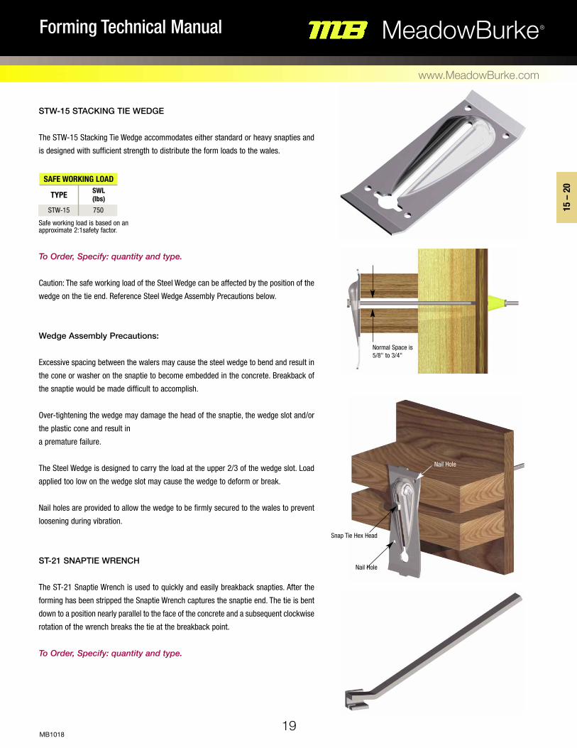
Normal Space is 5/8" to 3/4"
Snap Tie Hex Head
Nail Hole
Nail Hole
STW-15 STACKING TIE WEdGE
The STW-15 Stacking Tie Wedge accommodates either standard or heavy snapties and
is designed with sufficient strength to distribute the form loads to the wales.
To Order, Specify: quantity and type.
Caution: The safe working load of the Steel Wedge can be affected by the position of the
wedge on the tie end. Reference Steel Wedge Assembly Precautions below.
Wedge Assembly Precautions:
Excessive spacing between the walers may cause the steel wedge to bend and result in
the cone or washer on the snaptie to become embedded in the concrete. Breakback of
the snaptie would be made difficult to accomplish.
Over-tightening the wedge may damage the head of the snaptie, the wedge slot and/or
the plastic cone and result in
a premature failure.
The Steel Wedge is designed to carry the load at the upper 2/3 of the wedge slot. Load
applied too low on the wedge slot may cause the wedge to deform or break.
Nail holes are provided to allow the wedge to be firmly secured to the wales to prevent
loosening during vibration.
ST-21 SNAPTIE WrENCH
The ST-21 Snaptie Wrench is used to quickly and easily breakback snapties. After the
forming has been stripped the Snaptie Wrench captures the snaptie end. The tie is bent
down to a position nearly parallel to the face of the concrete and a subsequent clockwise
rotation of the wrench breaks the tie at the breakback point.
To Order, Specify: quantity and type.
SAFE WORKING LOADTYPE SWL
(lbs)STW-15 750
Safe working load is based on an approximate 2:1safety factor.
20
MeadowBurke®Forming Technical Manual
www.MeadowBurke.com
MB1018
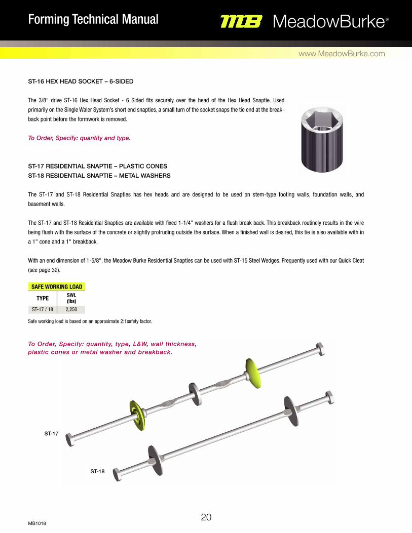
ST-18
ST-17
ST-16 HEX HEAd SOCKET – 6-SIdEd
The 3/8" drive ST-16 Hex Head Socket - 6 Sided fits securely over the head of the Hex Head Snaptie. Used
primarily on the Single Waler System’s short end snapties, a small turn of the socket snaps the tie end at the break-
back point before the formwork is removed.
To Order, Specify: quantity and type. ST-17 rESIdENTIAL SNAPTIE – PLASTIC CONES ST-18 rESIdENTIAL SNAPTIE – METAL WASHErS
The ST-17 and ST-18 Residential Snapties has hex heads and are designed to be used on stem-type footing walls, foundation walls, and
basement walls.
The ST-17 and ST-18 Residential Snapties are available with fixed 1-1/4" washers for a flush break back. This breakback routinely results in the wire
being flush with the surface of the concrete or slightly protruding outside the surface. When a finished wall is desired, this tie is also available with in
a 1" cone and a 1" breakback.
With an end dimension of 1-5/8", the Meadow Burke Residential Snapties can be used with ST-15 Steel Wedges. Frequently used with our Quick Cleat
(see page 32).
To Order, Specify: quantity, type, L&W, wall thickness, plastic cones or metal washer and breakback.
SAFE WORKING LOADTYPE SWL
(lbs)ST-17 / 18 2,250
Safe working load is based on an approximate 2:1safety factor.

21
21 –
28
MeadowBurke®Forming Technical Manual
www.MeadowBurke.com
MB1018
Single Waler System

22
MeadowBurke®Forming Technical Manual
www.MeadowBurke.com
MB1018
SINGLE WALER SYSTEM
The Meadow Burke Single Waler System is an economical, modern wall
forming method designed for use on straight, battered, curved and round-
ed walls and with various beam forms.
Whether your forming needs are for a four-foot knee wall or a twelve-foot
retaining wall, the Single Waler System can accommodate all of your hand-
set light forming requirements.
The complete System includes:
• Plastic cone or loose metal washer snapties
with 4-3/4" ends
• Single Waler Bracket
• Form Aligner Clamp for strongbacks
• Snap Jack for walls over 8' high
• Form Aligner
See Page 25 for typical installation sequence.
ST-10 SNAP BRACKET
The ST-10 Snap Bracket is the key element of the Single Waler System. It is fabricated
from heavy gauge steel and cadmium-plated for high corrosion resistance. This
versatile bracket can be installed horizontally, vertically or even inverted with a 2x4
kicker plate. The Snap Bracket uses 4-3/4" L&W snapties and its sliding wedge has a
5/8" adjustment range for minor lumber variation.
The brackets can be installed before or after the wales have been placed and have a
unique waler alignment feature not available on other brackets. Nailing the bracket
and/or wedge to the wales is not required, but nail holes are provided and strategically
placed, if needed.
To Order, Specify: quantity and type.
ST-11 FORM ALIGNER CLAMP The ST-11 Form Aligner Clamp provides the Single Waler System with a fast and easy way to attach 2x4 strongbacks to the form. The galvanized clamp can be installed ver-tically or horizontally at any point on the form. To Order, Specify: quantity and type.
23
21 –
28
MeadowBurke®Forming Technical Manual
www.MeadowBurke.com
MB1018
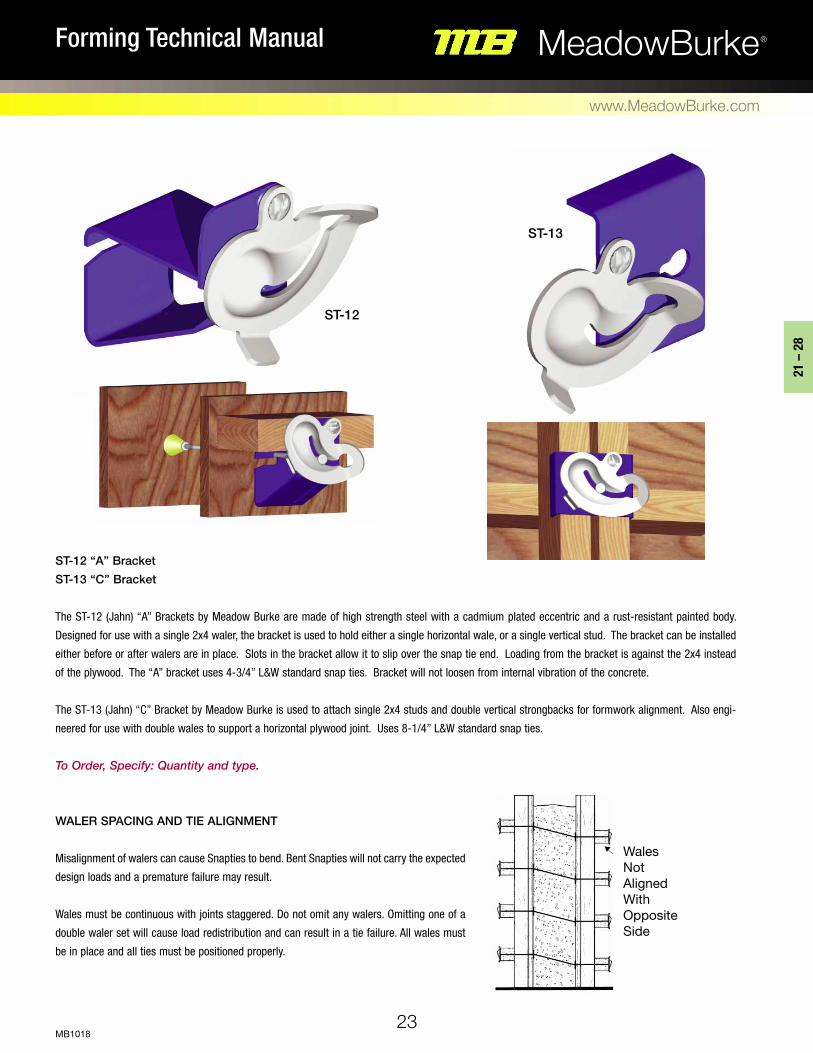
WALER SPACING AND TIE ALIGNMENT
Misalignment of walers can cause Snapties to bend. Bent Snapties will not carry the expected
design loads and a premature failure may result.
Wales must be continuous with joints staggered. Do not omit any walers. Omitting one of a
double waler set will cause load redistribution and can result in a tie failure. All wales must
be in place and all ties must be positioned properly.
Wales Not Aligned With Opposite Side
ST-12 “A” Bracket
ST-13 “C” Bracket
The ST-12 (Jahn) “A” Brackets by Meadow Burke are made of high strength steel with a cadmium plated eccentric and a rust-resistant painted body.
Designed for use with a single 2x4 waler, the bracket is used to hold either a single horizontal wale, or a single vertical stud. The bracket can be installed
either before or after walers are in place. Slots in the bracket allow it to slip over the snap tie end. Loading from the bracket is against the 2x4 instead
of the plywood. The “A” bracket uses 4-3/4” L&W standard snap ties. Bracket will not loosen from internal vibration of the concrete.
The ST-13 (Jahn) “C” Bracket by Meadow Burke is used to attach single 2x4 studs and double vertical strongbacks for formwork alignment. Also engi-
neered for use with double wales to support a horizontal plywood joint. Uses 8-1/4” L&W standard snap ties.
To Order, Specify: Quantity and type.
ST-12
ST-13
24
MeadowBurke®Forming Technical Manual
www.MeadowBurke.com
MB1018
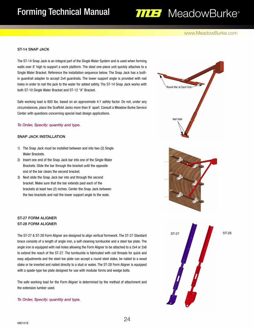
ST-14 SNAP JACK
The ST-14 Snap Jack is an integral part of the Single Waler System and is used when forming
walls over 8' high to support a work platform. The steel one-piece unit quickly attaches to a
Single Waler Bracket. Reference the installation sequence below. The Snap Jack has a built-
in guardrail adapter to accept 2x4 guardrails. The lower support angle is provided with nail
holes in order to nail the jack to the waler for added safety. Ths ST-14 Snap Jack works with
both ST-10 Single Waler Bracket and ST-12 “A” Bracket.
Safe working load is 800 lbs. based on an approximate 4:1 safety factor. Do not, under any
circumstances, place the Scaffold Jacks more than 8' apart. Consult a Meadow Burke Service
Center with questions concerning special load design applications.
To Order, Specify: quantity and type. SNAP JACK INSTALLATION
1) The Snap Jack must be installed between and into two (2) Single
Waler Brackets.
2) Insert one end of the Snap Jack bar into one of the Single Waler
Brackets. Slide the bar through the bracket until the opposite
end of the bar clears the second bracket.
3) Next slide the Snap Jack bar into and through the second
bracket. Make sure that the bar extends past each of the
brackets at least two (2) inches. Center the Snap Jack between
the two brackets and nail the lower support angle to the wale.
ST-27 FORM ALIGNER
ST-28 FORM ALIGNER
The ST-27 & ST-28 Form Aligner are designed to align vertical formwork. The ST-27 Standard
brace consists of a length of angle iron, a self-cleaning turnbuckle and a steel toe plate. The
angle iron is equipped with nail holes allowing the Form Aligner to be attached to a 2x4 or 2x6
to extend the reach of the ST-27. The turnbuckle is fabricated with coil threads for quick and
easy adjustments and the steel toe plate can accept a round steel stake, be nailed to a wood
stake or be inverted and nailed directly to a stud or wales. The ST-28 Form Aligner is equipped
with a spade-type toe plate designed for use with modular forms and wedge bolts.
The safe working load for the Form Aligner is determined by the method of attachment and
the extension lumber used.
To Order, Specify: quantity and type.
Round Bar at Each End
Nail Hole
ST-28ST-27

25
21 –
28
MeadowBurke®Forming Technical Manual
www.MeadowBurke.com
MB1018
SINGLE WALER FORMING APPLICATION
Gang Drilling Plywood
Gang drilling is a quick and economical way to prepare plywood for the single waler
forming application. Simply stack the plywood and drill the tie holes with a 5/8" drill
bit. The System works equally well with 5/8" or 3/4" plywood. The wedge take-up in
the bracket will compensate for thedifference in plywood thickness.
Common Spacing Layouts
4'
8"1-3/4"
1-3/4"
3/4"3/4"
14-1/4"
14-1/4"
16"
16"
16"
16"
16"
16"
16"
16"
16"
8"
4'
12"12"12"12" 24"24"
Maximum allowed form pressure is 4'-0" per hour at 70º F. Recommended 9/16" drill bit for form hole. Plywood thickness for this diagram is 3/4". Standard waler spacing is 16".
12 Holes You can minimize the amount of ties required with this standard spacing layout. You can also eliminate the need of a starter plate on 8' walls. Note: For l/360 deflection, use 12" waler spacing.
14 Holes This pattern is required for walls over 8' or when pan-els are to be attached to a kicker plate with inverted brackets. With this panel layout, the top waler is used to start the next tier of panels.

Wall Form Over 8ft. High • Single or Double 2x4 strongbacks with support clamps fastened to every other walerprovides a stable alignment for walls over 10 ft. • Nail a waler to top of last waler at plywood joint. • Nail aligner brace to vertical strongback at 1/3 height from top of form. • Only one side needed for bracing. • Form aligner brace spacing at 6 ft. on center.
Wall Form 8 ft. High • Attach strong- backs vertically to full height of form. • Use proper spacing to engage next row of ties, while attaching waler with form aligner clamps. • Easily attach plywood and secure with wrench head snapties and single waler forming brackets.
26
MeadowBurke®Forming Technical Manual
www.MeadowBurke.com
MB1018
SINGLE WALER BRACKET INSTALLATION
Wall Height Considerations
Snaptie spacing is dependent upon form pressure and the type of forming used. Below are a
few typical wall form spacing diagrams for various wall heights with pertinent notes for each
height.
Wall Form 4 ft. High • Install 4'x8' plywood horizontally. Attach 2x4 walers with horizontal tie-spacing of 2'-0" on center.
27
21 –
28
MeadowBurke®Forming Technical Manual
www.MeadowBurke.com
MB1018
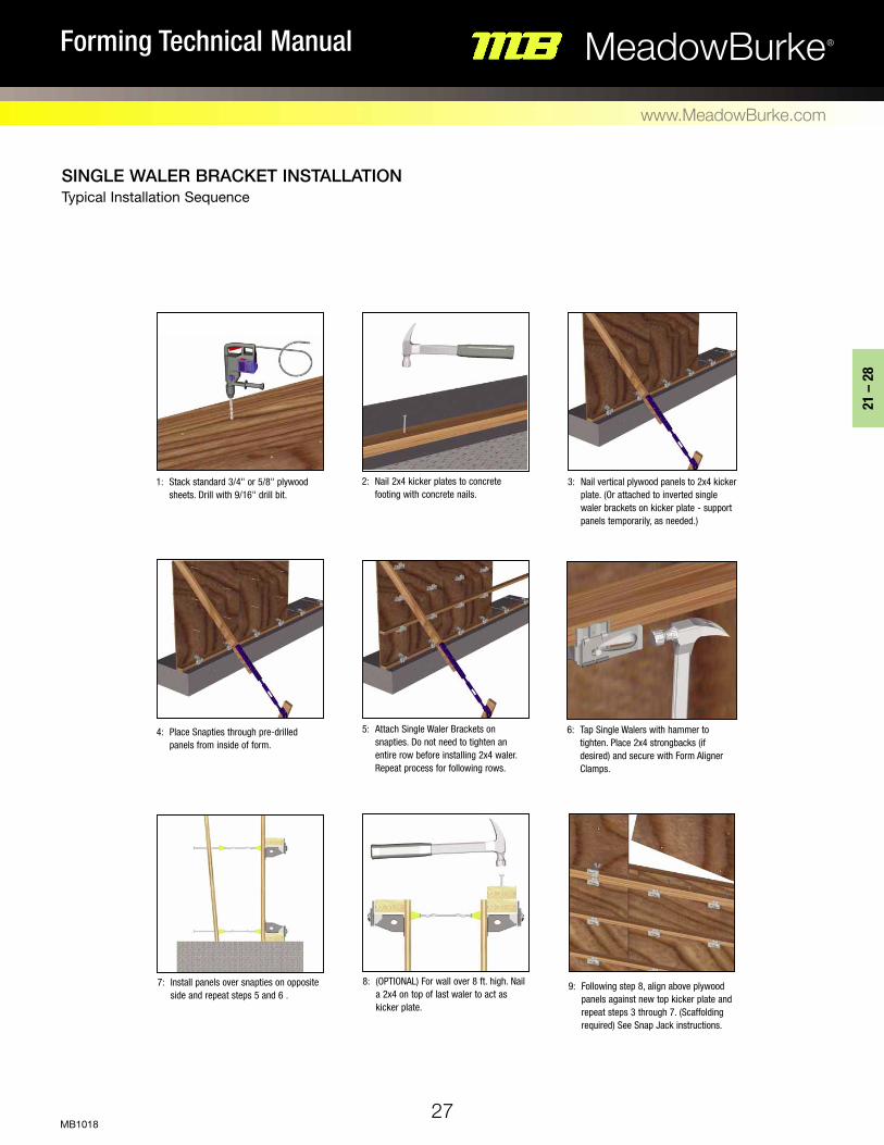
SINGLE WALER BRACKET INSTALLATION Typical Installation Sequence
7: Install panels over snapties on opposite side and repeat steps 5 and 6 .
8: (OPTIONAL) For wall over 8 ft. high. Nail a 2x4 on top of last waler to act as kicker plate.
9: Following step 8, align above plywood panels against new top kicker plate and repeat steps 3 through 7. (Scaffolding required) See Snap Jack instructions.
4: Place Snapties through pre-drilled panels from inside of form.
5: Attach Single Waler Brackets on snapties. Do not need to tighten an entire row before installing 2x4 waler. Repeat process for following rows.
6: Tap Single Walers with hammer to tighten. Place 2x4 strongbacks (if desired) and secure with Form Aligner Clamps.
1: Stack standard 3/4" or 5/8" plywood sheets. Drill with 9/16" drill bit.
2: Nail 2x4 kicker plates to concrete footing with concrete nails.
3: Nail vertical plywood panels to 2x4 kicker plate. (Or attached to inverted single waler brackets on kicker plate - support panels temporarily, as needed.)

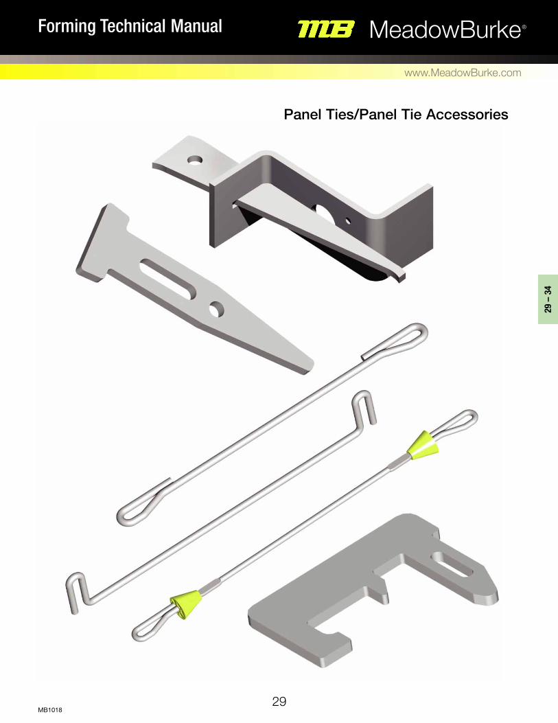
Panel Ties/Panel Tie Accessories
29
29 –
34
MeadowBurke®Forming Technical Manual
www.MeadowBurke.com
MB1018

30
MeadowBurke®Forming Technical Manual
www.MeadowBurke.com
MB1018
ST-23 LOOP TIE – STANDARD
ST-24 LOOP TIE – HEAVY
The ST-23 & ST-24 Loop Tie is designed for use with modular
forming systems. It is available in standard and heavy versions
and is supplied with 2-1/8" ends to accept the standard modular
form wedge bolt. The ST-23 Standard and ST-24 Heavy Loop Ties
come with a 1" breakback and without spreaders.
ST-25 GANG TIE – STANDARD ST-26 GANG TIE – HEAVY
The fabrication and use of the ST-25 & ST-26 Gang Tie is similar
to the Loop Tie, except the end dimension has been increased to
4-15/16". The longer end dimension is designed to accept the
typical modular forming gang wedge bolt. The longer end dimen-
sion allows the gang tie to be broken back before the formwork
is stripped.
To Order, Specify: quantity, type and wall thickness.
To Order, Specify: quantity, type and wall thickness.
To Order, Specify: quantity, type and wall thickness.
ST-29 LOOP TIE – PLASTIC CONE
ST-30 LOOP TIE – PLASTIC CONE H/D
The ST-29 & ST-30 Plastic Cone Loop Ties are similar to the stan-
dard Loop Ties, but are equipped with 1" plastic spreader cones
and 1" breakback.
SAFE WORKING LOAD
TYPE SWL (lbs)
ST-23 STD. ST-24 HVY.
2,250 3,000
Safe working load is based on an approximate 2:1safety factor.
SAFE WORKING LOAD
TYPE SWL (lbs)
ST-25 STD. ST-26 HVY.
2,250 3,000
Safe working load is based on an approximate 2:1safety factor.
SAFE WORKING LOAD
TYPE SWL (lbs)
ST-29 STD. ST-30 HVY.
2,250 3,000
Safe working load is based on an approximate 2:1safety factor.
1-1/8"1/4" 1-1/8"
Wall + 0.25"2" 2"
1-1/8" 1-1/8"Wall + 0.25"
2" 2"
Foreground panel omitted for clarity
Please refer to Snaptie & Looptie Don’ts on Page 15

31
29 –
34
MeadowBurke®Forming Technical Manual
www.MeadowBurke.com
MB1018
SB-1 STRONGBACK TIE
The SB-1 Strongback Tie is designed for use in conjunction with a Waler
Holder to attach the wales and double vertical strongbacks to modular
forms. Strongback Ties are available in three lengths to accommodate
various lumber combinations, as noted in the table.
Lumber Dimension Overall Length2x4 Wales plus 2x4
Strongbacks 2x4 Wales plus 2x6
Strongbacks 2x6 Wales plus 2x6
Strongbacks
9-3/4"
11-5/8"
13-1/2"
WT-1 WALER TIE
The WT-1 Waler Tie is similar to the Strongback Tie but has its ends
turned 90° to each other. This allows the use of a Waler Holder to attach
double wales to the modular form. The Waler Tie is available in two
lengths to accommodate 2x4 and 2x6 double horizontal wales.
Lumber Dimension Overall Length
Double 2x4 Wales
Double 2x6 Wales
6-3/16"
8-1/32"
BT-1 BASE TIE
The BT-1 Base Tie is designed to span two opposite modular forms and
the enclosed wall thickness at the bottom of the form and maintain the
proper wall dimension.
To Order, Specify: quantity, type and overall length.
To Order, Specify: quantity, type and overall length.
To Order, Specify: quantity, type and wall thickness.
Wall Thickness
Overall Length
Overall Length
1-5/32"1-5/32"

32
MeadowBurke®Forming Technical Manual
www.MeadowBurke.com
MB1018
FT-15 WEDGE BOLT
The FT-15 Wedge Bolt is designed to be used in pairs to securely
attach and hold adjacent modular forms and a loop tie together. To Order, Specify: quantity and type.
GW-16 GANG WEDGE BOLT
The GW-16 Gang Wedge Bolt is designed to hold adjacent mod-
ular forms together in combination with a Gang Tie. This provides
a means of tie breakback prior to form removal. To Order, Specify: quantity and type.
WH-1 WALER HOLDER
The WH-1 Waler Holder is designed to attach to a modular form with
a Waler Tie and securely support and tie double wales to the form. To Order, Specify: quantity and type.
Foreground panel omitted for clarity

33
29 –
34
MeadowBurke®Forming Technical Manual
www.MeadowBurke.com
MB1018
FT-4 FLAT TIE – TYPE M - STANDARD FT-4 FLAT TIE – TYPE M - HEAVY
The FT-4 Flat Tie Type M is similar in design, construction and use to the Standard (FT-1) Flat Tie, but has ends that are 5/8" shorter. Type M Flat Ties
are available in standard and heavy versions and have a 1/4" breakback.
FT-1 FLAT TIE – STANDARD FT-1 FLAT TIE – HEAVY
The FT-1 Flat Tie is designed for use on most standard modular forming systems. Both the Standard and Heavy versions utilize Wedge Bolts to
secure the formwork. Standard and Heavy Flat Ties are available in lengths 6" to 36" in 2" increments. Breakback is 1/4". Other lengths available on
special order.
FT-3 FLAT TIE – DUO - STANDARD FT-3 FLAT TIE – DUO - HEAVY
The FT-3 Duo Flat Tie is similar to the Standard Flat Tie (above) in design and use, but has two slot holes outboard of the breakback point. This feature
allows for the combination use of modular and wood formingelements. Duo Flat Ties are available in standard and heavy versions and have a normal
SAFE WORKING LOAD
TYPE SWL (lbs)
FT-1 STD. FT-1 HVY.
2,250 3,000
Safe working load is based on an approximate 2:1safety factor.
SAFE WORKING LOAD
TYPE SWL (lbs)
FT-3 STD. FT-3 HVY.
2,250 3,000
Safe working load is based on an approximate 2:1safety factor.
SAFE WORKING LOAD
TYPE SWL (lbs)
FT-4 STD. FT-4 HVY.
2,250 3,000
Safe working load is based on an approximate 2:1safety factor.
Tie LengthWall Thickness
Breakback
To Order, Specify: quantity, type and wall thickness.
To Order, Specify: quantity, type and wall thickness.
To Order, Specify: quantity, type and wall thickness.
Tie LengthWall Thickness
Breakback
Tie LengthWall Thickness
Breakback
34
MeadowBurke®Forming Technical Manual
www.MeadowBurke.com
MB1018
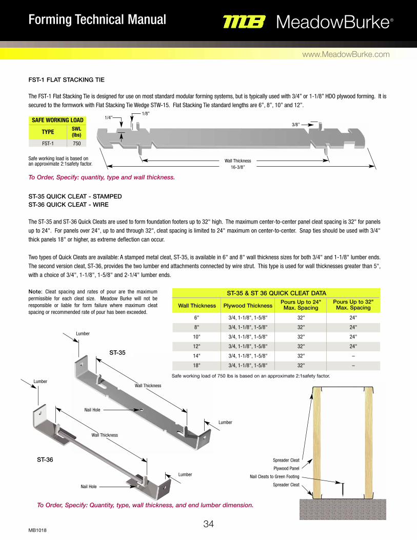
ST-35 QUICK CLEAT - STAMPED ST-36 QUICK CLEAT - WIRE The ST-35 and ST-36 Quick Cleats are used to form foundation footers up to 32" high. The maximum center-to-center panel cleat spacing is 32" for panels up to 24". For panels over 24", up to and through 32", cleat spacing is limited to 24" maximum on center-to-center. Snap ties should be used with 3/4" thick panels 18" or higher, as extreme deflection can occur. Two types of Quick Cleats are available: A stamped metal cleat, ST-35, is available in 6" and 8" wall thickness sizes for both 3/4" and 1-1/8" lumber ends. The second version cleat, ST-36, provides the two lumber end attachments connected by wire strut. This type is used for wall thicknesses greater than 5", with a choice of 3/4", 1-1/8", 1-5/8" and 2-1/4" lumber ends.
Note: Cleat spacing and rates of pour are the maximum permissible for each cleat size. Meadow Burke will not be responsible or liable for form failure where maximum cleat spacing or recommended rate of pour has been exceeded.
Nail Hole
Nail Hole
Wall Thickness
ST-35
ST-36 Spreader Cleat
Plywood Panel
Nail Cleats to Green Footing
Spreader Cleat
Lumber
Lumber
Wall Thickness
Lumber
Lumber
To Order, Specify: Quantity, type, wall thickness, and end lumber dimension.
Safe working load of 750 lbs is based on an approximate 2:1safety factor.
Wall Thickness Plywood ThicknessPours Up to 24" Max. Spacing
Pours Up to 32" Max. Spacing
6"
8"
10"
12"
14"
18"
3/4, 1-1/8", 1-5/8"
3/4, 1-1/8", 1-5/8"
3/4, 1-1/8", 1-5/8"
3/4, 1-1/8", 1-5/8"
3/4, 1-1/8", 1-5/8"
3/4, 1-1/8", 1-5/8"
32"
32"
32"
32"
32"
32"
24"
24"
24"
24"
–
–
ST-35 & ST 36 QUICK CLEAT DATA
FST-1 FLAT STACKING TIE The FST-1 Flat Stacking Tie is designed for use on most standard modular forming systems, but is typically used with 3/4” or 1-1/8” HDO plywood forming. It is secured to the formwork with Flat Stacking Tie Wedge STW-15. Flat Stacking Tie standard lengths are 6”, 8”, 10” and 12”.
SAFE WORKING LOAD
TYPE SWL (lbs)
FST-1 750
Safe working load is based on an approximate 2:1safety factor.
16-3/8”
1/4”
Wall Thickness
To Order, Specify: quantity, type and wall thickness.
1/8”
3/8”

Light, Medium and Heavy Forming Products
35
35 –
44
MeadowBurke®Forming Technical Manual
www.MeadowBurke.com
MB1018

36
MeadowBurke®Forming Technical Manual
www.MeadowBurke.com
MB1018
ST-19 PANEL LOCK TIE The ST-19 Panel Lock Tie is used in conjunction with a Steel Wedge to
quickly and securely lock adjacent form panel 2x4 studs together. The
standard length is 3-1/2" with other lengths available on special order. To Order, Specify: quantity, type and length. RD-24 PENCIL ROD The RD-24 Mild steel Pencil Rod is available in 1/4" diameter cut to 10',
20' or other specified length or in coils of approximately 600 feet (100
lbs.). 3/8" and 1/2" Pencil Rod are also available on special order.
To Order, Specify: quantity, type and diameter. RC-22 FORM CLAMP
The RC-22 Form Clamp is designed for use with the Pencil Rod, above, or
other similar mild steel bar. The clamp is available in three sizes to accept
1/4", 3/8" and 1/2" diameters. The Form Clamp is especially useful when
unusual forming conditions exist, such as battered walls or walls of vary-
ing thickness.
The safe working load of the Form Clamp is dependent on the setscrew
being properly tightened and the pencil rod being bent 90° at the back of
the clamp.
To Order, Specify: quantity, type and number.
SAFE WORKING LOAD
TYPE WIRE SIZE SWL (lbs)
RC-22 RC-22 RC-22
1/4" 3/8" 1/2"
NUMBER
1 2 3
1,125 2,250 3,750
Safe working load is based on an approximate 2:1safety factor.
Rod Tightener
Allow 9" Allow 4" Bend Rod
at 90º
Rod Clamp Rod Clamp

37
35 –
44
MeadowBurke®Forming Technical Manual
www.MeadowBurke.com
MB1018
RD-27 PLASTIC TUBING
The RD-27 Plastic Tubing is available for use when pencil rod must be
removed from set concrete. The tubing is cut to size and slipped over the
pencil rod to act as a sleeve to aid in the rod removal process. Plastic
Tubing is stocked in 1/4", 3/8", 1/2", 3/4" and 1" diameters in 5'
lengths.
To Order, Specify: quantity, type and diameter.
RD-25 PENCIL ROD TIGHTENER
The RD-25 Pencil Rod Tightener is used in conjunction with the pencil
rod/form clamp assembly to draw the formwork into position and hold it
securely while the rod clamp set screw is tightened. The Tightener is avail-
able in 1/4", 3/8" and 1/2" diameters to match the pencil rod diameter
being used.
To Order, Specify: quantity, type and diameter.
38
MeadowBurke®Forming Technical Manual
www.MeadowBurke.com
MB1018
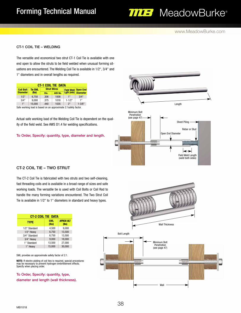
CT-1 COIL TIE – WELDING
The versatile and economical two strut CT-1 Coil Tie is available with one
end open to allow the struts to be field welded when unusual forming sit-
uations are encountered. The Welding Coil Tie is available in 1/2", 3/4" and
1" diameters and in overall lengths as required.
Actual safe working load of the Welding Coil Tie is dependent on the qual-
ity of the field weld. See AWS D1.4 for welding specifications.
To Order, Specify: quantity, type, diameter and length.
CT-2 COIL TIE – TWO STRUT The CT-2 Coil Tie is fabricated with two struts and two self-cleaning,
fast threading coils and is available in a broad range of sizes and safe
working loads. The versatile tie is used with Coil Bolts or Coil Rod to
handle the many forming variations encountered. The Two Strut Coil
Tie is available in 1/2" to 1" diameters in standard and heavy types.
Coil Bolt Diameter
Tie SWL (lbs)
Strut WiresAISI No.Dia.
Open End Diameter
Field Weld Lgth (min)
1/2" 3/4" 1"
6,750 9,000
15,000
.306
.375
.440
1008 1018 1035
1" 1-1/2"
2"
3/4" 1"
1-3/8"Safe working load is based on an approximate 2:1safety factor.
TYPE SWL (lbs)
APROX ULT (lbs)
1/2" Standard 1/2" Heavy
3/4" Standard 3/4" Heavy 1" Standard
1" Heavy
4,500 6,750 6,750 9,000
13,500 15,000
9,000 13,500 13,500 18,000 27,000 30,000
SWL provides an approximate safety factor of 2:1. NOTE: If electro-plating of coil ties is required, special procedures may be necessary to prevent hydrogen embrittlement effects. Specify when placing order.
To Order, Specify: quantity, type, diameter and length (wall thickness).
Rebar or Stud
Sheet Piling
Open End Diameter
Field Weld Length (weld both sides)
Bolt Length
Minimum Bolt Penetration
(see page 47)
Minimum Bolt Penetration
(see page 47)
Length
Wall Thickness
Wall
CT-2 COIL TIE DATA
CT-1 COIL TIE DATA

CAUTION: When pouring walls over 8' high, consider using the next higher load rated coil tie for additional safety factor. Form pressures tend to be greater than expected or planned when pouring higher walls. See Page 4 for additional safety information.
To Order, Specify: quantity, type, diameter, standard or heavy, tie length, wall thickness and setback. NOTE: To determine length, subtract two times the setback from the wall thickness.
39
35 –
44
MeadowBurke®Forming Technical Manual
www.MeadowBurke.com
MB1018
CT-2/CT-4 Coil Ties - Cone Fast The CT-2/CT-4 Coil Ties - Cone Fast are fabricated with longer coils that extend
beyond the ends of the struts to allow threaded plastic cones to be attached to
the Coil Tie. The cones provide a spreader function for the tie as well as a specific
setback. They also act as a centering guide when attaching the coil bolts during
setup.
Cone-Fast Coil Tie recesses left by the plastic cones provide an architectural
effect on the face of the concrete and the setback places the tie back away from
the concrete surface to reduce surface corrosion staining.
Two strut CT-2 Coil Tie - Cone Fast is available in 1/2", 3/4", and 1" standard
and heavy types. The four strut CT-4 Coil Tie - Cone Fast version is available
in 1" and 1-1/4" standard and 1-1/4" heavy.
Safe working loads of the Coil Tie - Cone-Fast are the same as the comparable
Two Strut and Four Strut Coil Ties. For additional safety information, refer to
page 4.
CT-4 COIL TIE – FOUR STRUT
The CT-4 Coil Tie - Four Strut is similar in form and use to the Coil Tie - Two
Strut, but has two additional struts to develop higher load capacities. Coil
Tie - Four Strut is available in 1" diameter standard, 1-1/4" standard and
1-1/4" heavy configurations.
CT-4 COIL TIE DATA
TYPE SWL (lbs)
1" Standard 1-1/4" Standard 1-1/4" Heavy
18,000 27,000 30,000
APROX ULT (lbs)
36,000 54,000 60,000
Safe working load is based on an approximate 2:1safety factor. NOTE: If electro-plating of coil ties is required, special procedures may be necessary to prevent hydrogen embrittlement effects. Specify when placing order.
To Order, Specify: quantity, type, diameter, standard or heavy and length (wall thickness).
Bolt Length
Wall
Bolt Length
Wall
Wall Thickness
Minimum Bolt Penetration (see page 47)
Minimum Bolt Penetration (see page 47)
Setback
CC-6 (page 48)
Tie Lengh=Wall Thickness minus 2 x setback
Tie Length
40
MeadowBurke®Forming Technical Manual
www.MeadowBurke.com
MB1018
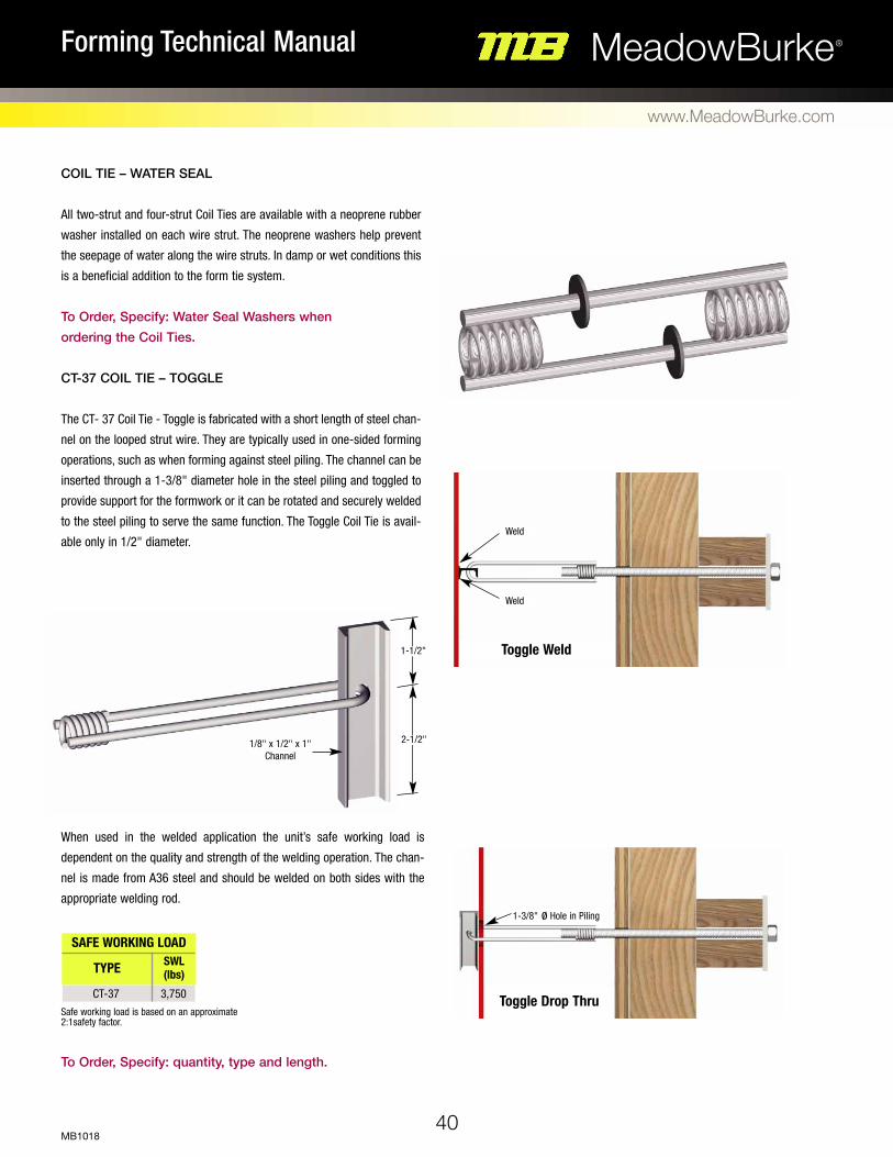
COIL TIE – WATER SEAL
All two-strut and four-strut Coil Ties are available with a neoprene rubber
washer installed on each wire strut. The neoprene washers help prevent
the seepage of water along the wire struts. In damp or wet conditions this
is a beneficial addition to the form tie system.
To Order, Specify: Water Seal Washers when ordering the Coil Ties.
CT-37 COIL TIE – TOGGLE The CT- 37 Coil Tie - Toggle is fabricated with a short length of steel chan-
nel on the looped strut wire. They are typically used in one-sided forming
operations, such as when forming against steel piling. The channel can be
inserted through a 1-3/8" diameter hole in the steel piling and toggled to
provide support for the formwork or it can be rotated and securely welded
to the steel piling to serve the same function. The Toggle Coil Tie is avail-
able only in 1/2" diameter.
When used in the welded application the unit’s safe working load is
dependent on the quality and strength of the welding operation. The chan-
nel is made from A36 steel and should be welded on both sides with the
appropriate welding rod.
To Order, Specify: quantity, type and length.
SAFE WORKING LOAD
TYPE SWL (lbs)
CT-37 3,750Safe working load is based on an approximate 2:1safety factor.
1/8" x 1/2" x 1" Channel
1-1/2"
1-3/8" ø Hole in Piling
Weld
Weld
Toggle Weld
Toggle Drop Thru
2-1/2"

41
35 –
44
MeadowBurke®Forming Technical Manual
www.MeadowBurke.com
MB1018
HD-9 TAPER TIE
The HD-9 Taper Tie manufactured from hi-strength steel with one size coil thread at one end and tapering to a smaller size coil thread at
the opposite end. The coil thread provides fast erection and stripping and the taper allows the tie to be easily extracted from the concrete. A
light bond preventing grease will help facilitate tie removal. The reusable tie is equipped with a square end for wrench turning capability and a hammer end
to aid in the extraction process. Standard sizes are shown in the Table, other lengths are available on special order.
3/4"
1"
1-1/4"
1-1/2"
34, 43, 52
30, 36, 42, 48, 54, 60
30, 36, 42, 48, 54, 60
30, 36, 42, 48, 54, 60
HD-9 TAPER TIE DATA
Large End Length (Inches)
11"
11"
11"
11"
7,500
18,000
34,000
50,000
Small End TSafe Working
Load (lbs)S
1/2"
3/4"
1"
1-1/4"
2 1/2"
6 1/2"
6 1/2"
6 1/2"
Safe working load is based on an approximate 2:1safety factor.
Length (Specify)
STaper LengthT
Hammer Point
Wall Thickness
To Order, Specify: quantity, type, diameter at each end, and length.

42
MeadowBurke®Forming Technical Manual
www.MeadowBurke.com
MB1018
HD-20 SHE BOLT
The HD-20 She Bolt is a heavy-duty, reusable form tie system furnished with external coil threads at one end and internal coil threads at the other.
Several inside rods are available for use with the She Bolt to tie formwork. They can also be effectively used with various form anchors to support
cantilevered forms. Like the Taper Tie, the She Bolt is furnished with a square end for wrench turning capability. Removal is enhanced by greasing
the embedded portion of the she bolt.
Outside Dia.
3/4"
1"
1-1/4"
1-1/2"
Inside Rod Dia.
A B CSafe
Working Load (lbs)
S T Standard Lengths (L)
1/2"
5/8"
3/4"
1"
1"
1"
1"
1"
1/2"
1/2"
3/4"
3/4"
1-1/2"
1-1/2"
2"
2"
2-3/4"
2-3/4"
4"
4"
10"
10"
10"
10"
20", 24"
20", 24"
20", 24"
24", 30"
9,000
12,000
18,000
37,500
Safe working load is based on an approximate 2:1safety factor.
HD-20 SHE BOLT DATA
C
LS
Wall Thickness
Inside Rod (see page 41)
Setback
TA
B
D
To Order, Specify: quantity, type, outside diameter, inside rod diameter, and length.
43
35 –
44
MeadowBurke®Forming Technical Manual
www.MeadowBurke.com
MB1018
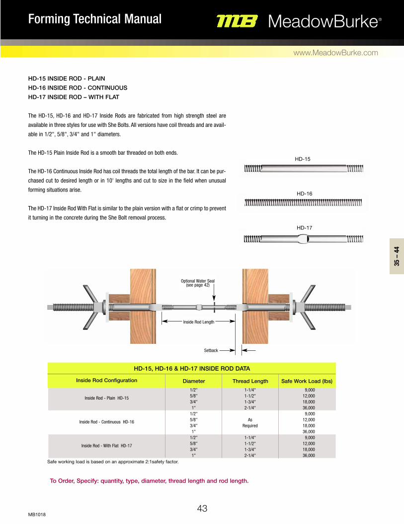
HD-15 INSIDE ROD - PLAIN HD-16 INSIDE ROD - CONTINUOUS HD-17 INSIDE ROD – WITH FLAT
The HD-15, HD-16 and HD-17 Inside Rods are fabricated from high strength steel are
available in three styles for use with She Bolts. All versions have coil threads and are avail-
able in 1/2", 5/8", 3/4" and 1" diameters.
The HD-15 Plain Inside Rod is a smooth bar threaded on both ends.
The HD-16 Continuous Inside Rod has coil threads the total length of the bar. It can be pur-
chased cut to desired length or in 10' lengths and cut to size in the field when unusual
forming situations arise.
The HD-17 Inside Rod With Flat is similar to the plain version with a flat or crimp to prevent
it turning in the concrete during the She Bolt removal process.
Inside Rod Configuration Diameter Thread Length Safe Work Load (lbs)9,000
12,000 18,000 36,000
9,000 12,000 18,000 36,000
9,000 12,000 18,000 36,000
Inside Rod - Plain HD-15
Inside Rod - Continuous HD-16
Inside Rod - With Flat HD-17
HD-15, HD-16 & HD-17 INSIDE ROD DATA
1/2" 5/8" 3/4" 1"
1/2" 5/8" 3/4" 1"
1/2" 5/8" 3/4" 1"
1-1/4" 1-1/2" 1-3/4" 2-1/4"
As
Required
1-1/4" 1-1/2" 1-3/4" 2-1/4"
Inside Rod Length
Optional Water Seal (see page 42)
Setback
HD-15
HD-16
HD-17
To Order, Specify: quantity, type, diameter, thread length and rod length.
Safe working load is based on an approximate 2:1safety factor.
44
MeadowBurke®Forming Technical Manual
www.MeadowBurke.com
MB1018
Safe working load is based on an approximate 2:1safety factor. NOTE: If setting-pin hole is required, it must be specified when ordering.
To Order, Specify: quantity, type, diameter and length.
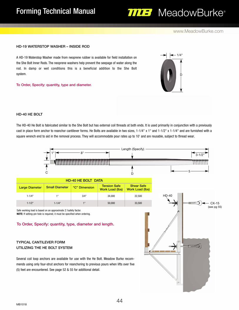
HD-19 WATERSTOP WASHER – INSIDE ROD
A HD-19 Waterstop Washer made from neoprene rubber is available for field installation on
the She Bolt Inner Rods. The neoprene washers help prevent the seepage of water along the
rod. In damp or wet conditions this is a beneficial addition to the She Bolt
system.
To Order, Specify: quantity, type and diameter.
HD-40 HE BOLT
The HD-40 He Bolt is fabricated similar to the She Bolt but has external coil threads at both ends. It is used primarily in conjunction with a previously
cast in place form anchor to reanchor cantilever forms. He Bolts are available in two sizes, 1-1/4" x 1" and 1-1/2" x 1-1/4" and are furnished with a
square wrench end to aid in the removal process. They will accommodate pour rates up to 10' and are reusable, subject to thread wear.
1-1/4"
1-1/2"
Large Diameter
22,500
33,500
Small Diameter
1"
1-1/4"
TYPICAL CANTILEVER FORM UTILIZING THE HE BOLT SYSTEM
Several coil loop anchors are available for use with the He Bolt. Meadow Burke recom-
mends using only four-strut anchors for reanchoring to previous pours when lifts over five
(5) feet are encountered. See page 52 & 55 for additional detail.
3/4"
1"
34,000
50,000
“C” Dimension Tension Safe Work Load (lbs)
Shear Safe Work Load (lbs)
Length (Specify)
DC
1"
5
CX-15 (see pg 55)
HD-40
8"3-1/2"
D
1/4"
HD-40 HE BOLT DATA
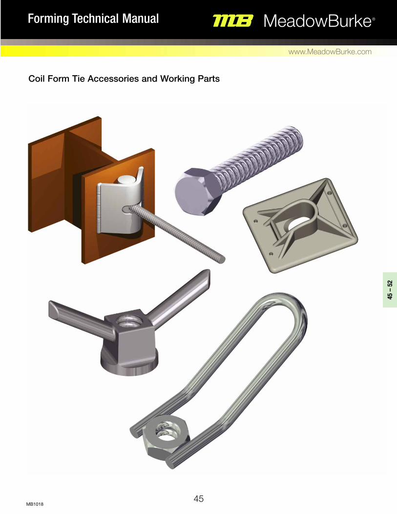
Coil Form Tie Accessories and Working Parts
45
45 –
52
MeadowBurke®Forming Technical Manual
www.MeadowBurke.com
MB1018

CN-5 Coil NuT – STANdARd
The CN-5 Standard Coil Nut
is manufactured from hex stock
and is available in 1/2"
through 1-1/2" diameters.
Dimensions are displayed in
the Table.
Note: In order to achieve the published safe working loads of Coil Bolts, Coil Rods, etc. when using the Standard Coil Nut; two (2) Standard Coil Nuts tightly locked together are required. To Order, Specify: quantity, type and diameter.
CN-25 Coil NuT – HeAvy
The CN-25 Heavy Coil Nuts
are manufactured from hex stock
like the Standard Coil Nut
but is of sufficient length
to develop the safe working
loads required for medium and heavy
form tying systems. To Order, Specify: quantity, type and diameter.
CN-25 Coil NuT - HeAvy dATA
diameter Flat Width (W)
Height (H)
Safe Work load (lbs)
CN-27 HANdle Coil NuT
The CN-27 Handle Coil Nut is fabricated by welding a substantial wire loop
to a Standard Coil Nut. The unit is designed to provide quick tightening and
release functions without the need of a wrench.
To Order, Specify: quantity, type and diameter.
CN-5 Coil NuT - STANdARd dATA
diameter Flat Width (W)
Height (H)
Safe Work load (lbs)
H
1/2"
3/4"
3/4"
1"
1-1/4"
1-1/2"
7/8"
1-1/8"
1-1/4"
1-5/8"
2"
2-3/8"
1/2"
5/8"
3/4"
1"
1-1/4"
1-1/2"
6,000
12,000
12,000
18,000
27,000
40,000
1/2"
3/4"
1"
1-1/4"
1-1/2"
7/8"
1-1/8"
1-5/8"
2"
2-3/8"
1"
1-1/2"
2"
2-1/2"
3"
9,000
18,000
38,000
56,000
68,000
H
W
46
MeadowBurke®Forming Technical Manual
www.MeadowBurke.com
MB1018
Safe working load is based on an approximate 2:1safety factor.
Safe working load is based on an approximate 2:1safety factor.
Safe working load is based on an approximate 2:1safety factor.
1/2"
3/4"
1"
1-1/4"
Coil Rod diameter
4,500
9,000
18,000
27,000
Safe Work load (lbs)
CN-27 HANdle Coil NuT dATA
5-1/4"
2"
W

D
1-3/8"
47
45 –
52
MeadowBurke®Forming Technical Manual
www.MeadowBurke.com
MB1018
CN-29 Coil WiNg NuT
The CN-29 Coil Wing Nuts are furnished with coil thread and are available in 1/2" through 1-1/2"
diameters. The ductile iron Coil Wing Nut offers high strength, speedy tightening and release.
To Order, Specify: quantity, type and diameter.
CW-4 FlAT WASHeR
The CW-4 Flat Washers are manufactured from high carbon flat steel plate and are designed to provide
the required bearing against the form members. Flat Washers are available in many sizes in both
standard and heavy versions. Refer to the Table for dimensions and safe working loads. To Order, Specify: quantity, type, standard or heavy and bolt diameter.
1/2"
3/4"
7/8"
1"
1-1/4"
1-1/2"
2-3/8"
2-1/2"
2-3/4"
3"
2-3/4"
2-3/4"
diameter d
1-3/8"
1-3/4"
1-3/4"
2"
2-1/4"
2-7/8"
9,000
18,000
18,000
38,000
52,000
80,000
l Safe Work load (lbs)
5"
5-7/8"
6"
6"
6-5/8"
6-3/4"
1-1/4"
1-1/4"
1-5/8"
1-5/8"
1-5/8"
1-7/8"
H W
1/2"
3/4"
1"
Hd-27 Coil NuT WASHeR dATAThread diameter
Safe Work load (lbs)d
3-3/4"
3-3/4"
5"
4,500
9,000
18,000
1/2"
3/4"
1"
1-1/4"
1-1/2"
1/2"
3/4"
1"
1-1/4"
1-1/2"
1/4 x 4 x 5
1/2 x 5 x 5
3/4 x 7 x 7
3/4 x 7 x 7
3/4 x 7 x 7
Standard Washer Heavy Washer
1/4 x 3 x 4
1/4 x 4 x 5
1/2 x 5 x 5
1/2 x 5 x 5
3/4 x 5 x 5
CN-29 Coil WiNg NuT dATA
CW-4 FlAT WASHeR dATA
Safe working load is based on an approximate 2:1safety factor.
Safe working load is based on an approximate 2:1safety factor.
Bolt dia. Size Bolt dia. Size
W
D
H
L
Hd-27 Coil NuT WASHeR
The HD-27 Coil Nut Washer is a one-piece ductile
iron unit that features both nut and washer. Coil
Nut Washers are available in 1/2", 3/4" and 1" coil
thread diameters and can be used with any coil
thread product with compatible diameter.
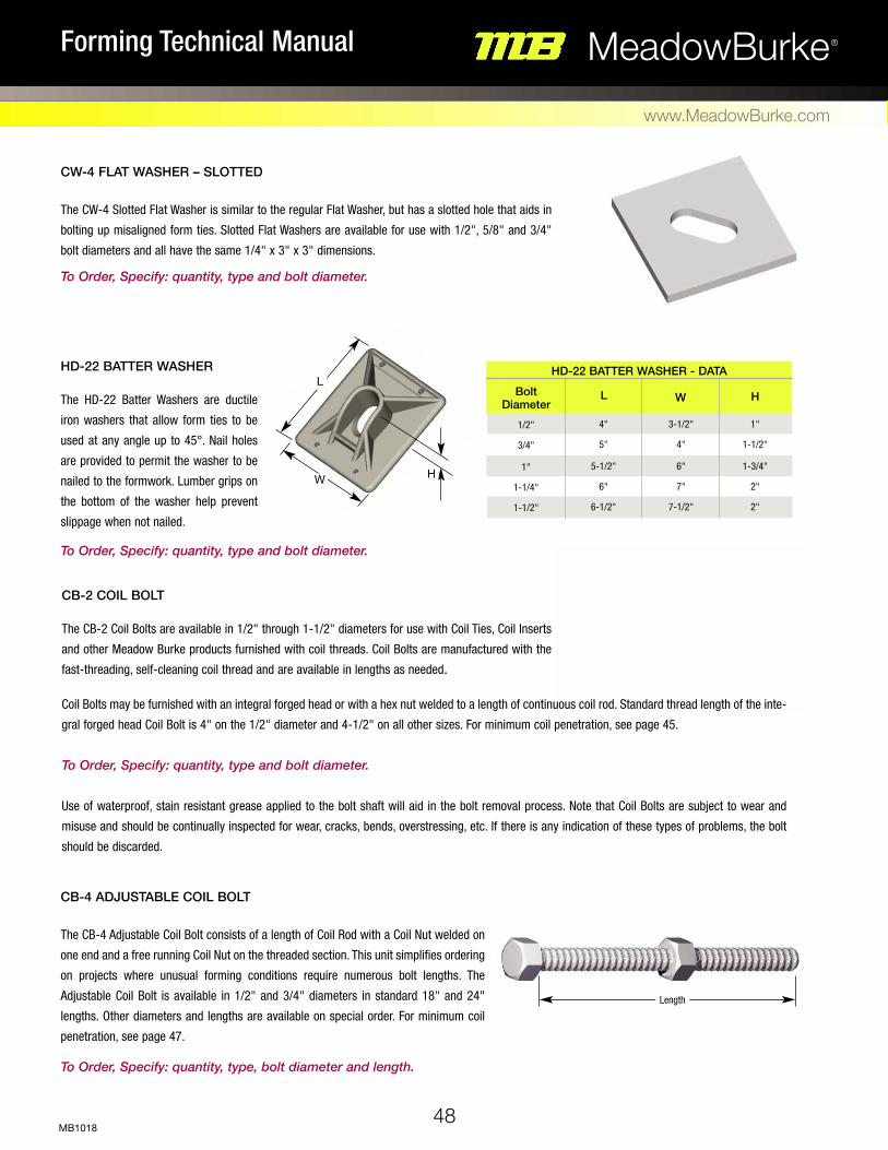
CB-4 AdJuSTABle Coil BolT
The CB-4 Adjustable Coil Bolt consists of a length of Coil Rod with a Coil Nut welded on
one end and a free running Coil Nut on the threaded section. This unit simplifies ordering
on projects where unusual forming conditions require numerous bolt lengths. The
Adjustable Coil Bolt is available in 1/2" and 3/4" diameters in standard 18" and 24"
lengths. Other diameters and lengths are available on special order. For minimum coil
penetration, see page 47. To Order, Specify: quantity, type, bolt diameter and length.
CW-4 FlAT WASHeR – SloTTed
The CW-4 Slotted Flat Washer is similar to the regular Flat Washer, but has a slotted hole that aids in
bolting up misaligned form ties. Slotted Flat Washers are available for use with 1/2", 5/8" and 3/4"
bolt diameters and all have the same 1/4" x 3" x 3" dimensions. To Order, Specify: quantity, type and bolt diameter.
CB-2 Coil BolT
The CB-2 Coil Bolts are available in 1/2" through 1-1/2" diameters for use with Coil Ties, Coil Inserts
and other Meadow Burke products furnished with coil threads. Coil Bolts are manufactured with the
fast-threading, self-cleaning coil thread and are available in lengths as needed.
Hd-22 BATTeR WASHeR
The HD-22 Batter Washers are ductile
iron washers that allow form ties to be
used at any angle up to 45°. Nail holes
are provided to permit the washer to be
nailed to the formwork. Lumber grips on
the bottom of the washer help prevent
slippage when not nailed. To Order, Specify: quantity, type and bolt diameter.
Coil Bolts may be furnished with an integral forged head or with a hex nut welded to a length of continuous coil rod. Standard thread length of the inte-
gral forged head Coil Bolt is 4" on the 1/2" diameter and 4-1/2" on all other sizes. For minimum coil penetration, see page 45.
To Order, Specify: quantity, type and bolt diameter.
Use of waterproof, stain resistant grease applied to the bolt shaft will aid in the bolt removal process. Note that Coil Bolts are subject to wear and
misuse and should be continually inspected for wear, cracks, bends, overstressing, etc. If there is any indication of these types of problems, the bolt
should be discarded.
1/2"
3/4"
1"
1-1/4"
1-1/2"
1"
1-1/2"
1-3/4"
2"
2"
Bolt diameter Wl
4"
5"
5-1/2"
6"
6-1/2"
3-1/2"
4"
6"
7"
7-1/2"
H
48
MeadowBurke®Forming Technical Manual
www.MeadowBurke.com
MB1018
Hd-22 BATTeR WASHeR - dATAL
H
Length
W

Coil BolT (CoNT.) MiNiMuM Coil PeNeTRATioN
1/2"
3/4"
1"
1-1/4"
1-1/2"
Coil Rod diameter
CR-4 Safe Work load (lbs)
CR-3 Safe Work loads (lbs)
---
12,000
24,000
36,000
54,000
9,000
18,000
38,000
56,000
68,000
CB-2 & CB-4 Coil BolT PeNeTRATioN dATA
Minimum Coil Penetration
3"
1-1/2" diameter
Treads per inch 3-1/2
1-1/4" diameter
56,000 40,000Tension68,000
Shear45,000
Minimum Coil Penetration
3"Treads per inch
3-1/2Treads per inch
3-1/2
Minimum Coil Penetration
2-1/2"Treads per inch
4-1/2
Minimum Coil Penetration
2-1/2"
Minimum Coil Penetration
2"
Treads per inch 6
Min. Root Area Square Inches .1385
Min. Root Area Square Inches .3080
Min. Root Area Square Inches .5410
Min. Root Area Square Inches .9160
Min. Root Area Square Inches 1.3890
1" diameter
25,00038,000
3/4" diameter
12,00018,000
1/2" diameter over 6"
6,0009,000
CR-3 Coil Rod - STANdARd CR-4 Coil Rod – Hi-STReNgTH
The CR-3 and CR-4 Coil Rods are manufactured from quality high-grade steel with
a full-length coil thread. It is available in 1/2" to 1-1/2" diameters cut to length or
in 10' or 12' lengths for field cutting. CR-3 Standard Coil Rod comes in 10' lengths and
CR-4 Hi-Strength Coil Rod is furnished in 12' lengths. Longer lengths are
available on special order. Coil Rod can be used with numerous other coil-threaded prod-
ucts to fashion an adjustable tie, an emergency tie, embedded as an adjustable anchor-
age, etc.
Note: 1/2" and 5/8" dia. is available only as CR-4 Hi-Strength Coil Rod. Coil Rod
requires two Standard Coil Nuts or one Heavy Coil Nut to develop the safe working loads
shown. Minimum coil penetration applies; see coil penetration warning above.
To Order, Specify: quantity, type, bolt diameter and length.
ShearShear TensionTensionTension ShearShearTension
WARNiNg: Minimum coil penetration is extremely important and must be adhered to when threading Coil Bolts into other coil-threaded prod-ucts. Safe working loads are dependent on maintaining the appropriate minimum coil penetration; failure to do so can lead to a premature fail-ure of the coil and compromise worker safety. Refer to the Table for safe working loads and minimum coil penetration lengths.
49
45 –
52
MeadowBurke®Forming Technical Manual
www.MeadowBurke.com
MB1018
CR-3 & CR-4 Coil Rod dATA
Safe working load is based on an approximate 2:1safety factor.
Safe working load is based on an approximate 2:1safety factor.

Hd-32 SToP CouPleR
The HD-32 Stop Coupler has coil threads tapped from each end creating a stop in the middle. Coil Rods or Inside Rods must be threaded to the
internal stop in order to achieve the listed safe working loads. To Order, Specify: quantity, type and thread diameter.
1/2"
3/4"
1"
9,000
18,000
38,000
Thread diameter ld
3/4"
1-1/16"
1-1/2"
2-1/2"
3"
4-1/2"
Safe Work load (lbs)
1/2"
1/2"
1/2"
3/4"
3/4"
1"
1-1/4"
1-1/4"
1-1/4"
1-1/4"
1-3/4"
1-3/4"
2-1/8"
2-3/8"
Bolt diameter lSetback
1"
1-1/2"
2"
1"
2"
2"
2"
1-3/8"
1-7/8"
2-3/8"
2-1/2"
2-1/2"
2-1/2"
2-1/2"
d
CC-6 CoNe-FAST CoNeS
The CC-6 Cone-Fast Cones are designed with inter-
nal coil threads to engage the protruding coils of the
Cone-Fast Coil Tie and provide a positive form
spreader action.
Cone-Fast Cones are stocked in all Cone-Fast Coil
Tie diameters. Reference the Table for cone dimen-
sions and setback. To Order, Specify: quantity, type, bolt diameter and setback.
CW-7 CoNe WReNCH
The CW-7 Cone Wrench is available in sizes corresponding to the Cone-Fast
Cones (above) to facilitate the removal of the cones from the concrete. To Order, Specify: quantity, type and bolt diameter.
50
MeadowBurke®Forming Technical Manual
www.MeadowBurke.com
MB1018
Cut away showing stop
CC-6 CoNe-FAST CoNeS dATA
Hd-32 SToP CouPleR dATA
Safe working loads are based on an approximate 2:1 safety factor.
D
L
L
D

CT-4 Coil Rod CouPleR
The CT-4 Coil Rod Coupler is a special four or six strut coil tie used in conjunction with Coil Rod to satisfy unusual forming conditions or variations. It is
available in 1/2", 3/4" and 1" diameters in the lengths shown in the Table.
To Order, Specify: quantity, type, diameter, and length.
CT-20 PlylAg
The CT-20 Plylag is designed to firmly attach wales and/or strongbacks
to modular forms or to provide an attachment method for coil threaded
products. The Plylag is available in 1/2" diameter. To Order, Specify: quantity, type and length.
Safe working load is based on an approximate 2:1safety factor.
1/2"
3/4"
1"
9,000
18,000
38,000
diameter length (l)Struts
4
4
6
8"
8"
10"
Safe Work load (lbs)
51
45 –
52
MeadowBurke®Forming Technical Manual
www.MeadowBurke.com
MB1018
CT-4 Coil Rod CouPleR dATA
Safe working load is based on an approximate 2:1safety factor.
L
B
L
Minimum Embedment is 30
Diameters
2-3/4"
1/2"
1/2"
1/2"
1/2"
diameter
6-1/4"
6-3/4"
9-3/4"
14-3/4"
length (l)
3-1/2"
4"
7"
12"
B
3,000
3,000
3,000
3,000
Safe Work load (lbs)
CT-20 PlylAg dATA

Hd-24 ANgle Weld BRACkeT
The HD-24 Angle Weld Bracket is designed to provide adjustability for one-sided forming applications. The bracket is available in 1/2", 3/4" and 1" thread
diameters and allows for 110° of maximum swing. The bracket can be welded to any steel construction member using proper welding techniques. The safe
loads displayed in the Table are approximate and are dependent on the quality of the weld. HD-24 Angle Weld Brackets are fabricated with ASTM A36 steel. To Order, Specify: quantity, type and thread diameter.
52
MeadowBurke®Forming Technical Manual
www.MeadowBurke.com
MB1018
0º
15º
30º
45º
55º
Angle
1/2"
3/4"
1"
1/4"
1/4"
1/2"
Thread diameter H
2-3/4"
2-3/4"
3"
9,000
18,000
32,000
W Safe Work load (lbs)
5"
5"
5"
3-1/4"
4-1/2"
6"
T d
Note: Load reduction factors due to angular loads on the Angle Weld Bracket can be figured as follows:
1) Select the appropriate angle.
2) Locate the corresponding load reduction factor in the Table.
3) Multiply the safe working load by the reduction factor.
Hd-24 ANgle Weld BRACkeT dATA
Hd-24 loAd ReduCTioN
Safe working load is based on an approximate 2:1safety factor.
1.000
0.966
0.866
0.707
0.500
Factor
WeldAngle Weld Bracket
55º Maximum
0º SWL
30º
45º
(.707 x SWL)
(.866 x SWL)
D
W
H
T
Coil Threaded Pivot Bar
Load
NoTe: HD-24 Angle Weld Bracket includes weld bracket
& pivot bar. Coil rod has to be ordered separately.

Coil Form Anchorage
53
53 –
62
MeadowBurke®Forming Technical Manual
www.MeadowBurke.com
MB1018
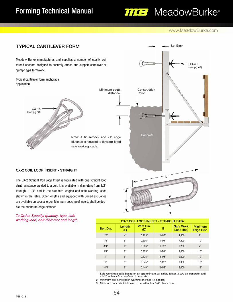
TyPICAL CANTILEvER FORM
54
MeadowBurke®Forming Technical Manual
www.MeadowBurke.com
MB1018
1/2"
1/2"
3/4"
3/4"
1"
1"
1-1/4"
1-1/8"
1-1/4"
1-5/8"
1-3/4"
2-1/8"
2-1/8"
2-1/2"
4,500
7,200
6,200
9,000
9,000
9,000
12,000
Bolt Dia. BWire Dia.
(D)Length
(L)Minimum Edge Dist.
4"
6"
4"
6"
6"
8"
8"
7"
10"
7"
10"
10"
13"
13"
0.225"
0.306"
0.306"
0.375"
0.375"
0.375"
0.440"
Safe Work Load (lbs)
Meadow Burke manufactures and supplies a number of quality coil
thread anchors designed to securely attach and support cantilever or
“jump” type formwork. Typical cantilever form anchorage application
CX-2 COIL LOOP INSERT - STRAIGHT
The CX-2 Straight Coil Loop Insert is fabricated with one straight loop
strut resistance welded to a coil. It is available in diameters from 1/2"
through 1-1/4" and in the standard lengths and safe working loads
shown in the Table. Other lengths and equipped with Cone-Fast Cones
are available on special order. Minimum spacing of inserts shall be dou-
ble the minimum edge distance. To Order, Specify: quantity, type, safe working load, bolt diameter and length.
1. Safe working load is based on an approximate 2:1 safety factor, 3,000 psi concrete, and a 1/2" setback from surface of concrete. 2. Minimum coil penetration warning on Page 47 applies. 3. Minimum concrete thickness = L + setback + 3/4" clear cover.
CX-2 COIL LOOP INSERT - STRAIGHT DATA
B
D
L
Note: A 6" setback and 21" edge distance is required to develop listed safe working loads.
Set Back
Minimum edge distance
CX-15 (see pg 53)
Construction Point
Concrete
HD-40 (see pg 42)

CX-4 COIL LOOP INSERT – FLARED
The CX-4 Flared Coil Loop Insert is manufactured with a flared loop strut
resistance welded to a coil. It is available in diameters from 3/4" through
1-1/2" and in the lengths and safe working loads shown for lifts up to 5'.
Minimum spacing of inserts shall be double the minimum edge distance. To Order, Specify: quantity, type, safe working load, bolt diameter and length.
55
53 –
62
MeadowBurke®Forming Technical Manual
www.MeadowBurke.com
MB1018
C
LW
DB
Flare Type Bolt Diameter Insert Length
(L)Safe Work Load (Tension) (lbs)
Concrete Strength PSI
B Coil Length (C)
Wire Diameter (D)
Flare Spread (W)
Minimum Edge Distance
Parallel Parallel Parallel Parallel Double Double Double Double Double Double
1" 1"
1-1/4" 1-1/4"
1" 1"
1-1/4" 1-1/4" 1-1/2" 1-1/2"
12" 12" 12" 12" 12" 12" 12" 12" 12" 12"
18,000 27,000 18,000 32,000 18,000 27,000 18,000 32,000 18,000 32,000
2,000 2,000 2,000 2,000 2,000 2,000 2,000 2,000 2,000 2,000
2-1/8" 2-1/2" 2-1/2" 2-1/2" 2-1/8" 2-1/2" 2-1/2" 2-1/2" 2-3/4" 2-3/4"
2-1/16" 2-1/16" 2-5/16" 2-5/16" 2-1/16" 2-1/16" 2-5/16" 2-5/16" 2-9/16" 2-9/16"
.375"
.440"
.375"
.440"
.375"
.440"
.375"
.440"
.375"
.440"
5 -1/2" 5-3/4" 5-3/4" 5-3/4" 5-1/2" 5-3/4" 5-3/4" 5-3/4" 5-3/4" 5-3/4"
15" 15" 15" 15" 15" 15" 15" 15" 15" 15"
E
1-1/4"
1-1/2"
5-3/4"
CX-6 COIL LOOP INSERTS - DOUBLE FLARED DATA
C
TOP vIEW DOUBLE PARALLEL
D
L
B
W E E
1. Safe working load is based on an approximate 2:1 safety factor, 3,000 psi concrete, and a 1/2" setback from surface of concrete. 2. Minimum coil penetration warning on Page 47 applies. 3. Minimum concrete thickness = L + setback + 3/4" clear cover.
1. Safe working load is based on an approximate 2:1 safety factor, 3,000 psi concrete, and a 1/2" setback from surface of concrete. 2. Minimum coil penetration warning on Page 47 applies. 3. Minimum concrete thickness = L + setback + 3/4" clear cover.
CX-6 COIL LOOP INSERT – DOUBLE FLARED
The CX-6 Double Flared Coil Loop Insert has two flared loop struts resistance welded
to the coil. It is available in the diameters, lengths and safe working loads displayed
in the Table. This insert is well suited for low strength concrete applications and can
easily accommodate 5' to 7-1/2' lifts. This insert can be ordered with straight loops.
Minimum spacing of inserts shall be double the minimum edge distance.
To Order, Specify: quantity, type, safe working load, bolt diameter and length.
Bolt Diameter
Insert Lgth (L)
Safe Work Load (Tension) (lbs) B Coil Length
(C)Concrete Strength
PSIWire Diameter
(D)Flare Spread
(W) Minimum Edge Distance
3/4" 3/4" 1" 1" 1" 1"
1-1/4" 1-1/4" 1-1/2"
6" 9" 9" 9"
12" 12" 12" 12" 12"
13" 13" 15" 15" 15" 15" 15" 15" 15"
9,000 9,000 9,000
13,500 9,000
13,500 9,000
15,000 15,000
2,000 2,000 2,000 2,000 2,000 2,000 2,000 2,000 2,000
3-1/2" 5-1/2" 5-1/2" 5-3/4" 5-1/2" 5-3/4" 5-3/4" 5-3/4" 5-3/4"
1-3/4" 1-3/4" 2-1/8" 2-1/2" 2-1/8" 2-1/2" 2-1/2" 2-1/2" 2-3/4"
1-3/4" 1-3/4" 2-1/16" 2-1/16" 2-1/16" 2-1/16" 2- 5/16" 2-5/16" 2-9/16"
.375"
.375"
.375"
.440"
.375"
.440"
.375"
.440"
.440"
CX-4 COIL LOOP INSERTS - FLARED DATA
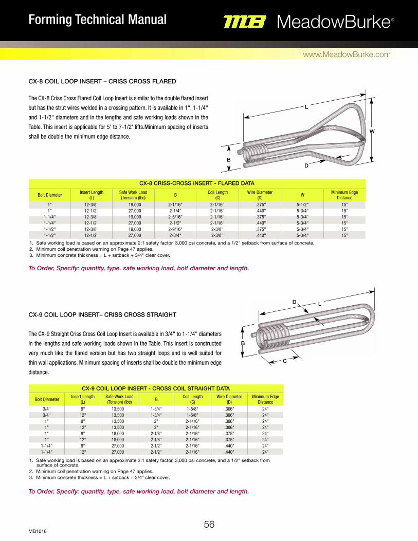
56
MeadowBurke®Forming Technical Manual
www.MeadowBurke.com
MB1018
1. Safe working load is based on an approximate 2:1 safety factor, 3,000 psi concrete, and a 1/2" setback from surface of concrete. 2. Minimum coil penetration warning on Page 47 applies. 3. Minimum concrete thickness = L + setback + 3/4" clear cover.
CX-9 COIL LOOP INSERT– CRISS CROSS STRAIGHT
The CX-9 Straight Criss Cross Coil Loop Insert is available in 3/4" to 1-1/4" diameters
in the lengths and safe working loads shown in the Table. This insert is constructed
very much like the flared version but has two straight loops and is well suited for
thin wall applications. Minimum spacing of inserts shall be double the minimum edge
distance.
To Order, Specify: quantity, type, safe working load, bolt diameter and length.
To Order, Specify: quantity, type, safe working load, bolt diameter and length.
The CX-8 Criss Cross Flared Coil Loop Insert is similar to the double flared insert
but has the strut wires welded in a crossing pattern. It is available in 1", 1-1/4"
and 1-1/2" diameters and in the lengths and safe working loads shown in the
Table. This insert is applicable for 5' to 7-1/2' lifts.Minimum spacing of inserts
shall be double the minimum edge distance.
CX-8 COIL LOOP INSERT – CRISS CROSS FLARED
Bolt Diameter Insert Length (L)
Safe Work Load (Tension) (lbs) B Coil Length
(C)Wire Diameter
(D) W Minimum Edge Distance
1" 1"
1-1/4" 1-1/4" 1-1/2" 1-1/2"
12-3/8" 12-1/2" 12-3/8" 12-1/2" 12-3/8" 12-1/2"
19,000 27,000 19,000 27,000 19,000 27,000
2-1/16" 2-1/4" 2-5/16" 2-1/2" 2-9/16" 2-3/4"
2-1/16" 2-1/16" 2-1/16" 2-1/16" 2-3/8" 2-3/8"
.375"
.440"
.375"
.440"
.375"
.440"
5-1/2" 5-3/4" 5-3/4" 5-3/4" 5-3/4" 5-3/4"
15" 15" 15" 15" 15" 15"
CX-8 CRISS-CROSS INSERT - FLARED DATA
Bolt Diameter Insert Length (L)
Safe Work Load (Tension) (lbs)
Minimum Edge DistanceB Coil Length
(C)Wire Diameter
(D)3/4" 3/4" 1" 1" 1" 1"
1-1/4" 1-1/4"
9" 12" 9"
12" 9"
12" 9"
12"
13,500 13,500 13,500 13,500 18,000 18,000 27,000 27,000
24" 24" 24" 24" 24" 24" 24" 24"
1-3/4" 1-3/4"
2" 2"
2-1/8" 2-1/8" 2-1/2" 2-1/2"
1-5/8" 1-5/8"
2-1/16" 2-1/16" 2-1/16" 2-1/16" 2-1/16" 2-1/16"
.306"
.306"
.306"
.306"
.375"
.375"
.440"
.440"
CX-9 COIL LOOP INSERT - CROSS COIL STRAIGHT DATA
L
L
D
D
C
B
W
B
1. Safe working load is based on an approximate 2:1 safety factor, 3,000 psi concrete, and a 1/2" setback from surface of concrete. 2. Minimum coil penetration warning on Page 47 applies. 3. Minimum concrete thickness = L + setback + 3/4" clear cover.
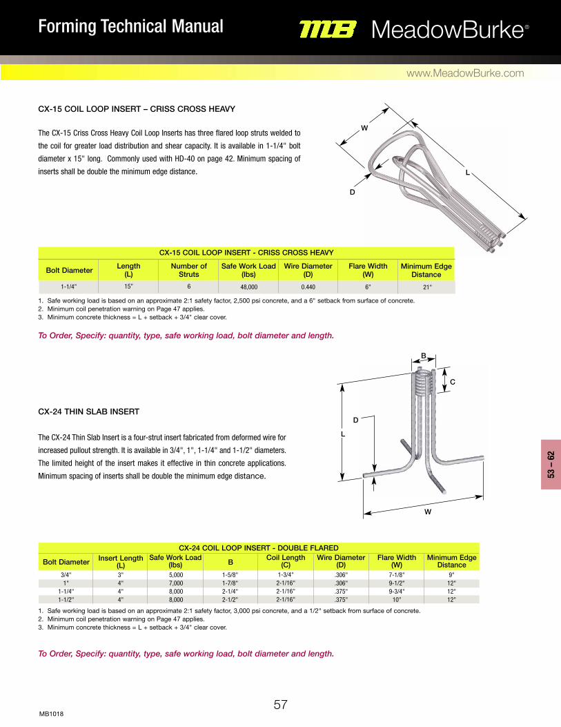
57
53 –
62
MeadowBurke®Forming Technical Manual
www.MeadowBurke.com
MB1018
CX-15 COIL LOOP INSERT – CRISS CROSS HEAvy
The CX-15 Criss Cross Heavy Coil Loop Inserts has three flared loop struts welded to
the coil for greater load distribution and shear capacity. It is available in 1-1/4" bolt
diameter x 15" long. Commonly used with HD-40 on page 42. Minimum spacing of
inserts shall be double the minimum edge distance.
CX-15 COIL LOOP INSERT - CRISS CROSS HEAvy
Bolt Diameter Length (L)
Number of Struts
Safe Work Load (lbs)
Wire Diameter (D)
Flare Width (W)
Minimum Edge Distance
CX-24 THIN SLAB INSERT
The CX-24 Thin Slab Insert is a four-strut insert fabricated from deformed wire for
increased pullout strength. It is available in 3/4", 1", 1-1/4" and 1-1/2" diameters.
The limited height of the insert makes it effective in thin concrete applications.
Minimum spacing of inserts shall be double the minimum edge distance.
1. Safe working load is based on an approximate 2:1 safety factor, 2,500 psi concrete, and a 6" setback from surface of concrete. 2. Minimum coil penetration warning on Page 47 applies. 3. Minimum concrete thickness = L + setback + 3/4" clear cover.
1. Safe working load is based on an approximate 2:1 safety factor, 3,000 psi concrete, and a 1/2" setback from surface of concrete. 2. Minimum coil penetration warning on Page 47 applies. 3. Minimum concrete thickness = L + setback + 3/4" clear cover.
D
B
W
C
L
Bolt Diameter Insert Length (L)
Safe Work Load (lbs) B Coil Length
(C)Wire Diameter
(D)Flare Width
(W)Minimum Edge
Distance3/4" 1"
1-1/4" 1-1/2"
3" 4" 4" 4"
5,000 7,000 8,000 8,000
1-5/8" 1-7/8" 2-1/4" 2-1/2"
1-3/4" 2-1/16" 2-1/16" 2-1/16"
.306"
.306"
.375"
.375"
7-1/8" 9-1/2" 9-3/4"
10"
9" 12" 12" 12"
CX-24 COIL LOOP INSERT - DOUBLE FLARED
D
W
L
To Order, Specify: quantity, type, safe working load, bolt diameter and length.
To Order, Specify: quantity, type, safe working load, bolt diameter and length.
1-1/4” 15” 6 48,000 0.440 6" 21"

B
58
MeadowBurke®Forming Technical Manual
www.MeadowBurke.com
MB1018
1. Safe working load is based on an approximate 2:1 safety factor, 3,000 psi concrete, and a 1/2" setback from surface of concrete. 2. Minimum coil penetration warning on Page 47 applies. 3. Minimum concrete thickness = L + setback + 3/4" clear cover. To Order, Specify: quantity, type, safe working load, bolt diameter and length.
1. Safe working load is based on an approximate 2:1 safety factor, 3,000 psi concrete, and a 1/2" setback from surface of concrete. 2. Minimum coil penetration warning on Page 47 applies. 3. Minimum concrete thickness = L + setback + 3/4" clear cover. To Order, Specify: quantity, type, safe working load, bolt diameter and length.
CX-28 COIL WINGNUT INSERT
The CX-28 Coil Wingnut Insert is designed for use in thin slabs or small sections to
attach secondary items or they can be used as nut on a length of Coil Rod in forming
applications. Refer to the chart for diameters, dimensions and safe working loads.
Minimum spacing of inserts shall be double the minimum edge distance.
Bolt Diameter Insert Length (L)
Width (W)
Safe Work Load (Tension) (lbs) B Coil Length
(C)Wire Diameter
(D)Minimum Edge
Distance1/2" 3/4" 3/4" 1" 1"
2-1/4" 2-1/4" 3-1/2" 2-1/2" 4-1/2"
4-1/8" 5" 6" 6" 6"
1,900 4,000 6,800 4,000 9,500
1-1/4" 1-5/8" 1-3/4"
2" 2"
1-1/8" 1-5/8"
2" 2" 2"
.225"
.262"
.306"
.306"
.306"
4" 5" 6" 5" 8"
CX-28 COIL WINGNUT INSERT DATA
9,000
12,000
15,000
12,000
18,000
18,000
18,000
27,000
CT-2 & CT-4 COIL TIE INSERT DATAInsert Type
Minimum Edge Distance
Wire Diameter (D)BSafe Work Load
(Tension) (lbs)Coil Length
(C)Insert Length
(L)Bolt Diameter
CT-2 COIL TIE INSERT – TWO STRUT CT-4 COIL TIE INSERT – FOUR STRUT
The versatile CT-2 and CT-4 Coil Ties are often used as inserts and are very effective in
reanchoring applications. The accompanying Table lists numerous standard sizes to fit a
broad range of applications. Other lengths are available, contact a Meadow Burke repre-
sentative for additional information. Minimum spacing of inserts shall be double the min-
imum edge distance.
CT-2
CT-2
CT-2
CT-4
CT-4
CT-4
CT-4
CT-4
3/4"
1"
1-1/4"
3/4"
1"
1"
1-1/4"
1-1/4"
6"
6"
8"
6"
8"
12"
8"
12"
8"
10"
10"
10"
10"
10"
10"
15"
1-5/8"
2-3/8"
2-1/2"
1-5/8"
2-1/16"
2-1/16"
2-1/2"
2-1/2"
1-3/4"
2-1/16"
2-1/16"
2-1/16"
2-1/16"
2-1/16"
2-1/16"
2-1/16"
.375"
.440"
.440"
.375"
.375"
.375"
.440"
.440"
L
W
L
L
D
D
D
C
B
B
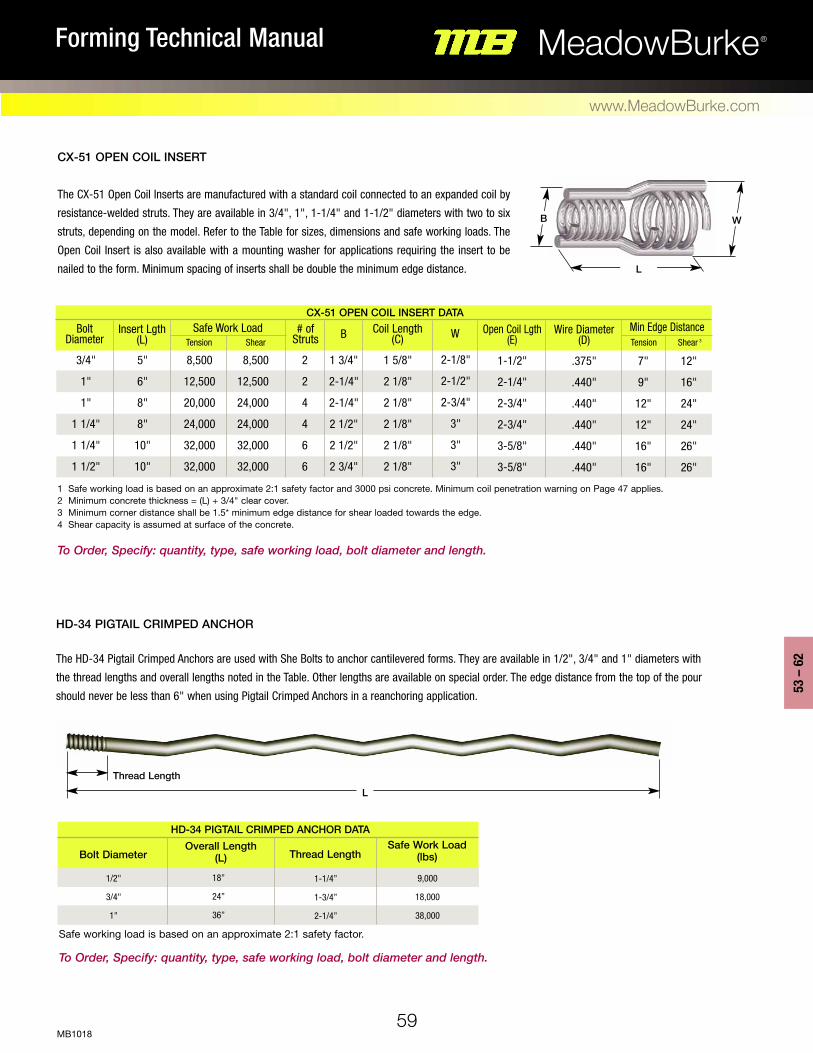
59
53 –
62
MeadowBurke®Forming Technical Manual
www.MeadowBurke.com
MB1018
1 Safe working load is based on an approximate 2:1 safety factor and 3000 psi concrete. Minimum coil penetration warning on Page 47 applies. 2 Minimum concrete thickness = (L) + 3/4" clear cover. 3 Minimum corner distance shall be 1.5* minimum edge distance for shear loaded towards the edge. 4 Shear capacity is assumed at surface of the concrete. To Order, Specify: quantity, type, safe working load, bolt diameter and length.
Safe working load is based on an approximate 2:1 safety factor. To Order, Specify: quantity, type, safe working load, bolt diameter and length.
HD-34 PIGTAIL CRIMPED ANCHOR
The HD-34 Pigtail Crimped Anchors are used with She Bolts to anchor cantilevered forms. They are available in 1/2", 3/4" and 1" diameters with
the thread lengths and overall lengths noted in the Table. Other lengths are available on special order. The edge distance from the top of the pour
should never be less than 6" when using Pigtail Crimped Anchors in a reanchoring application.
1-1/4”
1-3/4”
2-1/4”
Bolt Diameter
9,000
18,000
38,000
Overall Length (L)
1/2"
3/4"
1"
18”
24”
36”
Thread LengthSafe Work Load
(lbs)
5"
6"
8"
8"
10"
10"
8,500
12,500
20,000
24,000
32,000
32,000
8,500
12,500
24,000
24,000
32,000
32,000
1 5/8"
2 1/8"
2 1/8"
2 1/8"
2 1/8"
2 1/8"
2
2
4
4
6
6
.375"
.440"
.440"
.440"
.440"
.440"
2-1/8"
2-1/2"
2-3/4"
3"
3"
3"
1 3/4"
2-1/4"
2-1/4"
2 1/2"
2 1/2"
2 3/4"
1-1/2"
2-1/4"
2-3/4"
2-3/4"
3-5/8"
3-5/8"
7"
9"
12"
12"
16"
16"
12"
16"
24"
24"
26"
26"
3/4"
1"
1"
1 1/4"
1 1/4"
1 1/2"
CX-51 OPEN COIL INSERT DATA
HD-34 PIGTAIL CRIMPED ANCHOR DATA
Tension Shear Tension Shear 3W Open Coil Lgth
(E)Min Edge DistanceCoil Length
(C)# of
Struts BSafe Work Load Wire Diameter (D)
Insert Lgth (L)
Bolt Diameter
WB
L
Thread LengthL
CX-51 OPEN COIL INSERT
The CX-51 Open Coil Inserts are manufactured with a standard coil connected to an expanded coil by
resistance-welded struts. They are available in 3/4", 1", 1-1/4" and 1-1/2" diameters with two to six
struts, depending on the model. Refer to the Table for sizes, dimensions and safe working loads. The
Open Coil Insert is also available with a mounting washer for applications requiring the insert to be
nailed to the form. Minimum spacing of inserts shall be double the minimum edge distance.

60
MeadowBurke®Forming Technical Manual
www.MeadowBurke.com
MB1018
Safe working load is based on an approximate 2:1 safety factor.
HD-35 RADIUSED CRIMPED ANCHOR
The HD-35 Radiused Crimped Anchor is similar to the Pigtail Crimped Anchor but is
manufactured with a large radius to provide greater working loads in thin wall sections.
10"
12"
14"
4"
6"
8"
Bolt Diameter Overall Length (E)
1/2"
3/4"
1"
24"
30"
42"
Width (D) Radius (F)Safe Work Load
(lbs)
9,000
19,000
37,500
HD-35 RADIUSED CRIMPED ANCHOR DATA
D
F
R
E
CX-61
CX-62
CX-63
To Order, Specify: quantity, type, safe working load, bolt diameter and length.
To Order, Specify: quantity, type, bolt diameter, “L,” “W” and “R” dimension (if applicable).
WL
W
W
L
L
CX-61 Four Strut Coil Insert – Pigtail Crimped Anchor CX-62 Four Strut Coil Insert – Straight CX-63 Four Strut Coil Insert – Radiused
The CX-61, CX-62 and CX-63 Special inserts can be manufactured to meet your unusual forming requirements, and are often used as alter-
natives for cantilever formwork. The CX-61 is made using four pigtail crimped struts resistance welded to a coil. The CX-62 and CX-63 are made using
coil rod bent into a specified configuration. These products are made to order.
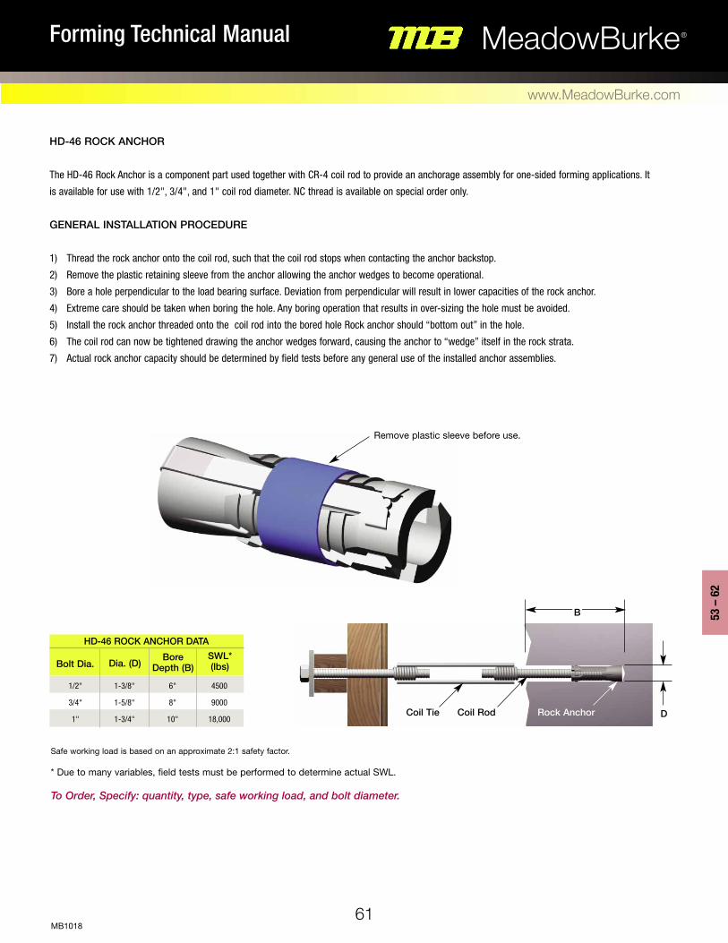
61
53 –
62
MeadowBurke®Forming Technical Manual
www.MeadowBurke.com
MB1018
Safe working load is based on an approximate 2:1 safety factor. * Due to many variables, field tests must be performed to determine actual SWL. To Order, Specify: quantity, type, safe working load, and bolt diameter.
D
B
Rock AnchorCoil RodCoil Tie
HD-46 ROCk ANCHOR
The HD-46 Rock Anchor is a component part used together with CR-4 coil rod to provide an anchorage assembly for one-sided forming applications. It
is available for use with 1/2", 3/4", and 1" coil rod diameter. NC thread is available on special order only.
GENERAL INSTALLATION PROCEDURE
1) Thread the rock anchor onto the coil rod, such that the coil rod stops when contacting the anchor backstop.
2) Remove the plastic retaining sleeve from the anchor allowing the anchor wedges to become operational.
3) Bore a hole perpendicular to the load bearing surface. Deviation from perpendicular will result in lower capacities of the rock anchor.
4) Extreme care should be taken when boring the hole. Any boring operation that results in over-sizing the hole must be avoided.
5) Install the rock anchor threaded onto the coil rod into the bored hole Rock anchor should “bottom out” in the hole.
6) The coil rod can now be tightened drawing the anchor wedges forward, causing the anchor to “wedge” itself in the rock strata.
7) Actual rock anchor capacity should be determined by field tests before any general use of the installed anchor assemblies.
Bolt Dia. Dia. (D) Bore Depth (B)
SWL* (lbs)
HD-46 ROCk ANCHOR DATA
Remove plastic sleeve before use.
1/2"
3/4"
1"
1-3/8"
1-5/8"
1-3/4"
6"
8"
10"
4500
9000
18,000


Euro Medium and Heavy Forming Products
63
63 –
68
MeadowBurke®Forming Technical Manual
www.MeadowBurke.com
MB1018

64
MeadowBurke®Forming Technical Manual
www.MeadowBurke.com
MB0118
12.5"
12.5"
15 mm
15 mm
0.813" to 705"
1" to 0.705"
12.5"
12.5"
18,750
18,750
Product Number taper dimension oa Lengthtaper
Length t sthread diameter
36"
42"
48"
54"
60"
36"
42"
48"
54"
60"
66"
MBETA1536
MBETA1542
MBETA1548
MBETA1554
MBETA1560
MBETB1536
MBETB1542
MBETB1548
MBETB1554
MBETB1560
MBETB1566
11"
17"
23"
29"
35"
11"
17"
23"
29"
35"
41"
safe Work Load (lbs)
Euro taPEr tiE
The Euro Threaded Taper Ties manufactured from high strength steel are used in forming applications, where complete removal of the forming system is
required. The tie features a unique thread which allows fast installation and stripping of the accessories. Available metric thread sizes are 15 mm
and 20 mm with different taper, taper length and overall length of the tie. Standard sizes are shown in the table below, other lengths are available on special
order.
15 MM Euro tHrEadEd taPEr tiEs
13"
13"
20 mm
20 mm
1" to 0.905"
1-1/4" to 0.905"
13"
13"
32,500
32,500
Product Number taper dimension oa Lengthtaper
Length t sthread diameter
16"
22"
28"
34"
16"
22"
28"
34"
safe Work Load (lbs)
20 MM Euro tHrEadEd taPEr tiEs
MB = Meadow Burke A/B = 1" to 0.905" / 1-1/4" to 0.905" E = Euro 20 = Thread Diameter T = Taper Tie 42 = OA Length
To Order, Specify: quantity, type, safe working load, bolt diameter, taper dimension & length, and overall length.
MB = Meadow Burke A/B = 0.813" to 0.705" / 1" to 0.705" E = Euro 15 = Thread Diameter T = Taper Tie 36 = OA Length
To Order, Specify: quantity, type, safe working load, bolt diameter, taper dimension & length, and overall length.
MBETA2042
MBETA2048
MBETA2054
MBETA2060
MBETB2042
MBETB2048
MBETB2054
MBETB2060
42"
48"
54"
60"
42"
48"
54"
60"
Overall Length
T Taper Length S
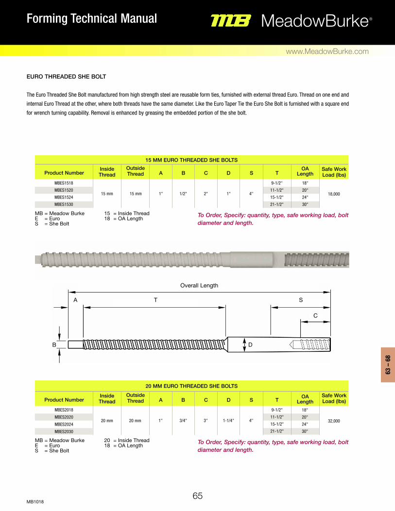
65
63 –
68
MeadowBurke®Forming Technical Manual
www.MeadowBurke.com
MB1018
15 mm 15 mm 1" 1/2" 2" 1" 4"
1" 3/4" 3" 1-1/4" 4"
18,000
Product Number a B C d s toa
Lengthinside thread
outside thread
safe Work Load (lbs)
Euro tHrEadEd sHE BoLt
The Euro Threaded She Bolt manufactured from high strength steel are reusable form ties, furnished with external thread Euro. Thread on one end and
internal Euro Thread at the other, where both threads have the same diameter. Like the Euro Taper Tie the Euro She Bolt is furnished with a square end
for wrench turning capability. Removal is enhanced by greasing the embedded portion of the she bolt.
15 MM Euro tHrEadEd sHE BoLts
20 mm 20 mm 32,000
Product Number a B C d s t oa Length
inside thread
outside thread
safe Work Load (lbs)
20 MM Euro tHrEadEd sHE BoLts
18"
20"
24"
30"
MB = Meadow Burke 15 = Inside Thread E = Euro 18 = OA Length S = She Bolt
MB = Meadow Burke 20 = Inside Thread E = Euro 18 = OA Length S = She Bolt
18"
20"
24"
30"
9-1/2"
11-1/2"
15-1/2"
21-1/2"
9-1/2"
11-1/2"
15-1/2"
21-1/2"
MBES2018
MBES2020
MBES2024
MBES2030
MBES1518
MBES1520
MBES1524
MBES1530
To Order, Specify: quantity, type, safe working load, bolt diameter and length.
To Order, Specify: quantity, type, safe working load, bolt diameter and length.
Overall Length
TA S
C
DB

66
MeadowBurke®Forming Technical Manual
www.MeadowBurke.com
MB0118
Euro Bar – Hot roLLEd
Meadow Burke’s Euro Bar – Hot rolled is made of high strength steel and has two flat sides in its thread pattern. It is compatible with all Euro Threaded products,
and the flat sides provides a self-cleaning feature to the bar. Standard stocking length of the bar is 19'-0", but shorter lengths are available upon request.
Euro Nut WasHEr
The Euro Threaded Nut Washer features a washer base to distribute the applied loads over the form members, and helps to reduce the number of loose working
parts used on the production site. It is compatible with the cold rolled and hot rolled Euro Threaded Bar. See table for dimensions.
Euro Bar – CoLd roLLEd
Meadow Burke’s Euro Bar – Cold rolled is made of high strength steel and available in 15 mm and 20 mm sizes. The bar is fully rolled with Euro thread. A 2.5
thread pitch, ensures a fast intallation and stripping process. Standard stocking length of the bar is 20'-0" but shorter lengths are available upon request.
Product Number oa Lengththread diameter safe Work Load (lbs)
Euro Bar - CoLd roLLEd
15 mm
20 mm
MBEC15240
MBEC20240
20'-0"
20'-0"
20,000
32,000
MB = Meadow Burke 15 = Thread Diameter E = Euro C = Cold Rolled
To Order, Specify: quantity, type, safe working load, bolt diameter and length.
Product Number oa Lengththread diametersafe Work Load (lbs)
Euro Bar - Hot roLLEd
19'-0"
19'-0"
22,400
39,200
MB = Meadow Burke H = Hot Rolled E = Euro 15 = Thread Diameter
To Order, Specify: quantity, type, safe working load, bolt diameter and length.
Product Number a b c dthread diameter
safe Work Load (lbs)
Euro Nut WasHEr
4"
4"
2"
2"
1-3/8"
1-5/8"
1-3/16"
1-7/16"
22,400
39,200
MB = Meadow Burke NW = Nut Washer E = Euro 15 = Thread Diameter
To Order, Specify: quantity, type, safe working load, and bolt diameter.
MBEH15236
MBEH20236
15mm
20mm
15 mm
20 mm
MBENW15
MBENW20 B
A
C
D

D
W
H
T
67
63 –
68
MeadowBurke®Forming Technical Manual
www.MeadowBurke.com
MB1018
Euro sWiVEL WiNG Nut
The Euro Threaded Swivel Wing Nut features a heavy dudy washer based with ribs, to reduce the number of loose working parts used on the production
site. It is compatible with the cold rolled and hot rolled Euro Threaded Bar. See table for dimensions.
Euro aNGLE WELd BraCKEt
The Euro Angle Weld Bracket is designed to provide adjustability for one-sided forming applications. The bracket is available in 15 mm and 20 mm threaded
diameters and allows for a 110º of maximum swing. The bracket can be welded to any steel construction member using proper welding techniques. The safe
working loads in the table are approximate, and are dependent on the quality of the weld
Euro tHrEadEd WiNG Nut
Euro Threaded Wing Nut is compatible with the cold rolled and hot rolled Euro Threaded Bar. See table for dimensions.
Product Number a b c dthread diameter
safe Work Load (lbs)
Euro sWiVEL WiNG Nut
15 mm
20 mm
MBESWN15
MBESWN20
4-11/16"
4-11/16"
2-3/8"
2-3/8"
1-3/8"
1-5/8"
1-3/16"
1-7/16"
22,400
39,200
To Order, Specify: quantity, type, safe working load and bolt diameter.
Product Number a b c dthread diameter
safe Work Load (lbs)
Euro tHrEadEd WiNG Nut
15 mm
20 mm
MBETWN15
MBETWN20
3-9/16"
3-9/16"
2-3/8"
2-3/8"
1-3/8"
1-5/8"
1-3/16"
1-7/16"
22,400
39,200
0º
15º
30º
45º
55º
angle
Euro aNGLE Load rEduCtioN
1.000
0.966
0.866
0.707
0.500
Factor
Product Number W H t dthread diameter
safe Work Load (lbs)
Euro aNGLE WELd BraCKEt
15 mm
20 mm
MBEAWB15
MBEAWB20
5"
5"
4-1/2"
6"
1/4"
3/8"
2-3/4"
3"
22,400
39,200
MB = Meadow Burke AWB = Angle Weld Bracket E = Euro 15 = Thread Diameter To Order, Specify: quantity, type, safe working load and bolt diameter.
MB = Meadow Burke E = Euro
SWN = Swivel Wing Nut 15 = Thread Diameter
To Order, Specify: quantity, type, safe working load and bolt diameter.
MB = Meadow Burke E = Euro
TWN = Threaded Wing Nut 15 = Thread Diameter
0º SWL
30º
45º
(.707 x SWL)
(.866 x SWL)
Load
WeldEuro
Threaded Pivot Bar
Note: Euro Angle Weld Bracket includes weld bracket and pivot bar. Euro rod must be ordered separately.
B
C
A
D
A
C
D
B

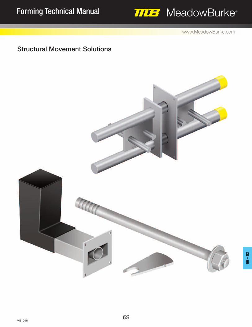
69
69 –
82
MeadowBurke®Forming Technical Manual
www.MeadowBurke.com
MB1016
Structural Movement Solutions

70
PERMANENT MOVEMENT SOLUTION: BURKE DOUBLE SHEAR DOWEL
MeadowBurke®Forming Technical Manual
www.MeadowBurke.com
MB1016
The Burke Double Shear Dowel System offers signifi-cant advantages over conventional structural move-ment methods. The two part assembly is a simplesolution that allows longitudinal and/or Lateral move-ment in building joints. The Burke Double Shear Dowelconsists of a sleeve and dowel component.
Quick installation eliminates the need for formwork pen-etration or concrete protrusions. The easy accurate placement process ensures proper dowel alignment, which is essential for effective movement.
Our shear connectors are manufactured from duplex stainless steel toensure a high degree of corrosion resistance with no requirement for additionalprotection.
BURKE DOUBLE SHEAR DOWEL ASSEMBLY
The Burke Double Shear Dowel is the original two-part, double dowel, shear loadconnector. The dowel component allows longitudinal movement within the sleeve.The connector is available in 10 standard sizes with design capacities from approximately 4.500 kips to more than 213 kips. The Burke Dou-ble Shear Dowel easily accommodates joint widths up to 2-3/8”. Larger jointscan be accommodated using special dowels.
BURKE DOUBLE SHEAR DOWEL – FQ
The Burke Double Shear Dowel–FQ shear load connector utilizes the same dowel(male) component as the Burke Double Shear Dowel in conjunction with a sleevecomprising a rectangular box sleeve to allow lateral movement in addition to thelongitudinal movement. There are nine standard sizes withdesign capacities from approximately 7.8 kips to more than 213 kips.
Double Shear Dowel–FQ allowing rotation
Double Shear Dowel–FQ Connectors
Slab Movement inOpposite Directions
Double Shear Dowel–FQ allowingmovement in two directions

71
69 –
82
MeadowBurke®Forming Technical Manual
www.MeadowBurke.com
MB1016
End Cap
Cross Dowels
End Plate with Nail Holes
LongitudinalMovement
Guide Tube
Web Plate
Dowel Bar
DOUBLE SHEAR DOWEL
Sleeve within Rectangular Box Section
Longitudinal Movement
Lateral Movement or Rotation
DOUBLE SHEARDOWEL–FQ
Smooth Dowel
Keyed Joint
Double Columns
Corbel Support
Double Shear Dowel andDouble Shear Dowel – FQ
Double Shear Dowel andDouble Shear Dowel – FQ
Double Shear Dowel andDouble Shear Dowel – FQ
Double Shear Dowel andDouble Shear Dowel – FQ
Conventional Joints - Floor Slab Floor Slab / Elevated Floor Slab
Wall
Structural Movement Joint
Floor to Wall Connection
OUR PROVEN SOLUTIONAccommodating movement during transmission of trans-verse forces may be accommodated in many ways.Double Shear Dowels provide a proven method to replacedowelled or keyed joints in most cases. The Double ShearDowel connectors can be used for movement joints in floorslabs, suspended slabs, and keyed joints in walls. Theyare also ideal for eliminating the need for double columnswhile opening up a valuable space. They are also an effective solution for costly cast-in-place corbel systems.Corbel support can be eliminated totally while maintainingstructural movement. The unique design of the DoubleShear Dowel provides significant load improvement oversmooth dowels. The example below shows the compari-son between one DSD/DSDFQ 130 and six traditionalsmooth round dowels.
COMPARISON OF PERFORMANCE with Plain Dowels @ 5,000 psi
One Shear Load Connector 130 Design Capacity 45.5 kips
Six Dowel Bars 1.25" DiaDesign Capacity 44.4 kips
15.75" Thick Slab withJoint Width of 0.75"
One MB DSD 130
Six 1.25" DiaDowel Bars
Dowel Dia inches2 2 x 1.375 6 x 1.25
Area of Dowels inches2 2.969 7.5
Design Capacity( kip) 55.31 52.14

72
REINFORCEMENT DETAILS
MeadowBurke®Forming Technical Manual
www.MeadowBurke.com
MB1016
225
202
180
157
135
112
90
67
45
22
0
DSD 450DSD 400DSD 150DSD 130DSD 100DSD 75DSD 65DSD 50DSD 30DSD 25
0.393" 0.787" 1.181" 1.574" 1.968" 2.362"
Burke Double Shear Dowel FRd design capabilities (kips) for various joint widths(mm) at the maximum slab thickness(inch) in 4000 psi concrete
F Rd
(kip
s)
REINFORCEMENT DETAILS
Local reinforcement is required around each connector to guarantee that the forces aretransferred between the connectors and the concrete. Correct detailing in accordance withappropriate design codes and the recommendations provided here will ensure BurkeDouble Shear Dowels attain their full capacity.
The tables show proposals for the type and spacing of the main reinforcement, together withdetails of reinforcement above and below the connectors.
Longitudinalreinforcement
above connectors
Longitudinalreinforcement
below connectorsMain
reinforcementeach side of connector
Main reinforcementeach side of connector
Based on 3000 psi, maximum slab depth, .787" joint width Number of U Bars each side
2530506575
100130150400450
23345-----
-23345----
-----34679
------3457
DSD/DSDFQ #3 #4 #5 #6
#3 #4 #5 #6
#3 #4 #5 #6
#3 #4 #5 #6
Number of U Bars Top and Bottom
2530506575
100130150400450
23345-----
-23345----
-----34679
------3457
DSD/DSDFQ
Based on 3000 concrete, max slab depth & 0.787" joint
Based on 4000 psi, maximum slab depth, .787" joint width Number of U Bars each side
2530506575
100130150400450
3---------
23345-----
-23345----
----345---
DSD/DSDFQ
Number of U Bars Top and Bottom
2530506575
100130150400450
3---------
23345-----
-23345----
----345---
DSD/DSDFQ

73
INSTALLATION PROCEDURE
69 –
82
MeadowBurke®Forming Technical Manual
www.MeadowBurke.com
MB1016
The two-part assembly of all Burke shear connectors removes the need for drilling formwork on site, supportingdowel bars and fitting debonding sleeves and end caps, making the installation process both fast and accurate.
Notes:(i) Where deep concrete pours are proposed, the installation will require further consideration.
More robust fixing of the sleeve and dowel components will be necessary to avoid displacement during placing of the concrete.
Nail the sleeve component to the shuttering ensuring that the sleeve is correctly orientated forthe direction of the load. Check that theminimum spacing and edge distances are not ex-
ceeded. The label prevents debris from entering intothe sleeve aperture and should not be removed atthis stage.
Fix the local reinforcement in position around thedowel component together with any other reinforcement that is required, ensuring that thecorrect cover to the reinforcement is maintained. Pour the concrete to complete the installation of theshear connector.
When the concrete has achieved sufficient strength,strike the shuttering.
Position compressible joint filler of the appropriatewidth, for applications where movement is expected between the two sections of concrete.
Push the dowel component through the joint filler (ifapplicable) until it is fully located in the sleeve com-ponent. It may be necessary to tap the dowel com-ponent to overcome the dimple, which pinch holdsthe dowel in the sleeve and prevents dislocationwhen the concrete is vibrated.
Fix the local reinforcement in position around the sleeve component together with any otherreinforcement that is required, ensuring that thecorrect cover to the reinforcement is maintained.
2
53 4
1
6 7
Direction of Load

74
TEMPORARY MOVEMENT SOLUTION: BURKE LOCKABLE DOWEL
MeadowBurke®Forming Technical Manual
www.MeadowBurke.com
MB1016
REVOLUTIONIZING POST-TENSIONED PRECAST CONCRETE
The Burke Lockable Dowel has been designed for use at temporary move-
ment joints, most commonly found in post-tensioned concrete frames.
These dowels allow initial shrinkage of the concrete to take place and are
then locked in position with a mechanical plate and a controlled amount of
epoxy resin. The locked dowels continue to transfer shear, but prevent further
movement taking place.
ADVANTAGES
The use of Burke Lockable Dowels can save a significant amount of time and
materials over other construction methods. Concrete shrinkage has traditionally
been accommodated by leaving gaps in the slab called “pour strips” or “closure
strips.” These strips are filled once movement has stabilized, however until
they are filled the slabs must be shored, restricting site access and delaying
site progress. Gaps in the slab also create a hazard for site workers, use
additional formwork and leave the soffit face marked.
Lockable Dowels improve site access, minimize formwork requirements and
accelerate the rate of construction. With a Lockable Dowel, there is
less requirement for the slabs to be shored or a support corbel to be
constructed, as shear load is transferred by the dowel. The time saved by early
removal of slab props can be significant.
A Lockable Dowel also provides many advantages over the site-assembled
arrangement of carbon steel reinforcing bar, galvanized or plastic ducting, vent
tubes and a non-specific grout, which is sometimes used by contractors.
In addition, engineers have found the Burke Lockable Dowel to be the
preferred design solution for pin-ended joints. Although it is customary for prac-
tical reasons to use U-bars or other rebar continuity systems at these
connections, these options do not truly act as hinges and so rotation of the slab
under load can induce cracking at the wall-to-slab interface with
potential integrity issues.
The Lockable Dowel is closer to a true pin-ended joint and, being manufactured
from stainless steel, provides additional corrosion protection over systems using
carbon steel reinforcement.

75
APPLICATIONS
69 –
82
MeadowBurke®Forming Technical Manual
www.MeadowBurke.com
MB1016
Preliminary Pour Using theBurke Lockable Dowel
Finished Slab Using the Burke Lockable Dowel
Traditional Pour Strip
In most cases, Burke Lockable Dowels can be used to replace pour strips at temporary movement joints in post-tensioned concrete frames. Burke Lockable
Dowels and DSD Shear Load Connectors are available for use at slab joints and retaining / core walls.
SLAB-TO-SLAB
Burke Lockable Dowel
Proven performance Minimal material usage
Various site-assembled components
Unreliable performance, additional construction materials used and support corbel required
SLAB-TO-WALL
Burke Lockable Dowel
Improved site access Reduced shoring timeSimple installationEliminates framework obstacles
Pour strip at wall-to-slab junction
Pour strip in slab
Burke Lockable Dowel
Proven performance Minimal material usageSimple installationImproved on-site safety
Additional formwork, trip hazard and restricted accessSlabs shored for several weeks
Restricted accessSlabs shored for several weeks

76
MeadowBurke®Forming Technical Manual
www.MeadowBurke.com
MB1016
RANGE OF LOCKABLE DOWELS
A Lockable Dowel allows initial shrinkage of the
concrete to take place and then, after a predetermined
time period (generally 30 to 90 days), is locked in position
with a mechanical plate and a controlled amount of epoxy
resin. The range comprises three products; ESDQ-L20,
HLDQ-L30 and ESDQ-L20W.
SLAB-TO-SLAB LOCKABLE DOWELS
ESDQ-L20
The dowel component is manufactured from 30mm
diameter stainless steel; one end is threaded with a fixed
nut and washer, and the other features a series of grooves
to accept the Locking Plate. The cylindrical sleeve which
accepts the dowel component is contained within a
box-section to allow lateral, longitudinal and some
rotational movement. The epoxy resin is poured into the
L-shaped void former. This product has a design capacity of
almost two quarts.
SLAB-TO-WALL LOCKABLE DOWEL
ESDQ-L20W
The dowel component is manufactured from 30mm
diameter stainless steel, but is shorter than the ESDQ-L20
dowel. One end of the dowel is designed to thread into the
stainless steel Burke SKS24 Threaded Anchor cast into the
face of the concrete and the other end features a series
of grooves to accept the Locking Plate. The sleeve
component is the same as used in the ESDQ-L20. See pages
6-9 for full technical details.
HLDQ-L30
The HLDQ-L30 is a high load Lockable Dowel with a
design capacity of up to 30.6 kips.
ESDQ-L20for Slab-to-Slab
Locking Plate
Dowel Component
Dowel Component
SKS24 Threaded Anchorsupplied with a nailing plate
Sleeve Component featuringvoid former supplied withlabel on nailing plate
Sleeve Component featuringvoid former supplied withlabel on nailing plate
Sleeve Component featuringvoid former supplied withlabel on nailing plate
Dowel Component
Locking Plate
Locking Plate
ESDQ-L20Wfor Slab-to-Wall
HLDQ-L30for Slab-to-Slab

SLAB-TO-WALLAPPLICATION
77
EPOXY RESIN
Each dowel is locked after a pre-determined time period (generally 3-4 weeks) with a high quality, two-
part epoxy resin. The resin is mixed and poured into the L-shaped void former. Each dowel
requires 1,500g of resin which can be supplied either in a single can for one application or bulk pack-
aging for locking multiple dowels.
69 –
82
MeadowBurke®Forming Technical Manual
www.MeadowBurke.com
MB1016
“The Burke Lockable Dowel is a very clean sys-tem compared to pour strips. Pour strips are anightmare! Pour strips are a mess with all theshoring, safety concerns, cables, cleaning, fill up,and conduit problems. Any extra money spenton the Lockable Dowel is well worth the benefit.The Lockable Dowel saved about 3 weeks withthis project. The Lockable Dowel is so clean noone noticed there was a pour strip.
If you have encountered pour strips before, theLockable Dowel is a no brainer.
You would be crazy not to use it!“
Mahmoud FarawiSkanska USARaleigh, NC
Two-part Epoxy Resinsupplied with:
ESDQ-L20ESDQ-L20WHLDQ-L30
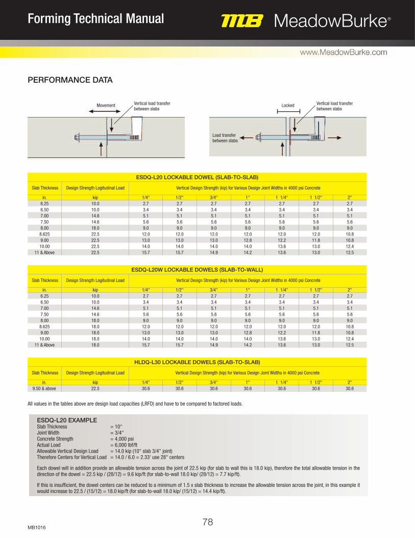
78
PERFORMANCE DATA
MeadowBurke®Forming Technical Manual
www.MeadowBurke.com
MB1016
ESDQ-L20 EXAMPLESlab Thickness = 10"Joint Width = 3/4"Concrete Strength = 4,000 psiActual Load = 6,000 lbf/ftAllowable Vertical Design Load = 14.0 kip (10" slab 3/4" joint)Therefore Centers for Vertical Load = 14.0 / 6.0 = 2.33' use 28" centers
Each dowel will in addition provide an allowable tension across the joint of 22.5 kip (for slab to wall this is 18.0 kip), therefore the total allowable tension in the direction of the dowel = 22.5 kip / (28/12) = 9.6 kip/ft (for slab-to-wall 18.0 kip/ (28/12) = 7.7 kip/ft).
If this is insufficient, the dowel centers can be reduced to a minimum of 1.5 x slab thickness to increase the allowable tension across the joint, in this example itwould increase to 22.5 / (15/12) = 18.0 kip/ft (for slab-to-wall 18.0 kip/ (15/12) = 14.4 kip/ft).
Slab Thickness Design Strength Logitudinal Load Vertical Design Strength (kip) for Various Design Joint Widths in 4000 psi Concrete
in.6.256.507.007.508.00
8.6259.00
10.0011 & Above
kip10.010.014.614.618.022.522.522.522.5
1/4"2.73.45.15.69.0
12.013.014.015.7
1/2"2.73.45.15.69.012.013.014.015.7
3/4"2.73.45.15.69.012.013.014.014.9
1"2.73.45.15.69.0
12.012.814.014.2
1 1/4"2.73.45.15.69.012.012.213.613.6
1 1/2"2.73.45.15.69.012.011.813.013.0
2"2.73.45.15.69.010.810.812.412.5
ESDQ-L20 LOCKABLE DOWEL (SLAB-TO-SLAB)
Slab Thickness Design Strength Logitudinal Load Vertical Design Strength (kip) for Various Design Joint Widths in 4000 psi Concrete
in.6.256.507.007.508.00
8.6259.00
10.0011 & Above
kip10.010.014.614.618.018.018.018.018.0
1/4"2.73.45.15.69.0
12.013.014.015.7
1/2"2.73.45.15.69.012.013.014.015.7
3/4"2.73.45.15.69.012.013.014.014.9
1"2.73.45.15.69.0
12.012.814.014.2
1 1/4"2.73.45.15.69.012.012.213.613.6
1 1/2"2.73.45.15.69.012.011.813.013.0
2"2.73.45.15.69.010.810.812.412.5
ESDQ-L20W LOCKABLE DOWELS (SLAB-TO-WALL)
Slab Thickness Design Strength Logitudinal Load Vertical Design Strength (kip) for Various Design Joint Widths in 4000 psi Concrete
in.9.50 & above
kip22.5
1/4"30.6
1/2"30.6
3/4"30.6
1"30.6
1 1/4"30.6
1 1/2"30.6
2"30.6
HLDQ-L30 LOCKABLE DOWELS (SLAB-TO-SLAB)
Movement Locked
Load transferbetween slabs
Vertical load transferbetween slabs
Vertical load transferbetween slabs
All values in the tables above are design load capacities (LRFD) and have to be compared to factored loads.

79
DIMENSIONS
69 –
82
MeadowBurke®Forming Technical Manual
www.MeadowBurke.com
MB1016
4"
ESDQ-L20 COMPONENTSDOWEL COMPONENT
SLEEVE COMPONENT
HLDQ-L30 COMPONENTSDOWEL COMPONENT
SLEEVE COMPONENT
ESDQ-L20W COMPONENTSSKS24 THREADED ANCHOR
SLEEVE COMPONENTDOWEL COMPONENT
EDGE DISTANCE AND SPACINGSFor connectors working at or near their maximum capacity, theminimum spacing should be 1.5 times the slab thickness. Wherethe design load of the connector could be used in a thinner slab,a spacing of 1.5 times the thinner slab thickness can be used.The minimum end distance is always 0.5 times the spacing.
1-3/16"1-1/4" Internal
Diameter 6-1/2"
5-1/2"
1-5/8"
4-1/16"
1-3/16"
10-1/2"M30x3.5mm
3-5/8"
6"
1-3/16"
10-1/2"
19"4-1/2"
18" 9-1/2"
1-1/4" Internal Diameter
6-1/2"
11"
Max 1-1/2" LateralMovement
5-1/2"
7" 1/4"1/4"
Max 1-1/2" LateralMovement
4-1/2"
1-1/4" Internal Diameter 6-1/2"
9-1/2"
1-1/2" LateralMovement 4"
4-1/2"
h
10" min.
min. 0.75h min. 1.5h
min. 0.75h min. 1.5h
7-1/2" min. 15" min.
ESDQ-L20 Minimum Edge Distance and Spacings
HLDQ-L30 Minimum Edge Distance and Spacings
ESDQ-L20W Minimum Edge Distance and Spacings
ESDQ-L20 EXAMPLESlab Thickness = 12"Joint Width = 1"Concrete Strength = 4,000 psiAllowable Load/Connector = 14.2 kip/ft(based on slabs 10" and above)Spacing for Max. Load 12" x 1.5 = 18"End Distance for Max. Load 18" x 0.5 = 9"Allowable Load/Foot = 14.2 kip/ (18/12) = 9.5 kip/ft
As an ESDQ L20 can be used in a 7" slab for a reduced allowable loadper connector of up to 9,500 lbf, the spacing can be based on a 7" slab.Therefore:Reduced Spacing 7" x 1.5 = 10-1/2"Reduced End Distance 10-1/2" x 0.5 = 5-1/4"Allowable Load/Foot 9.5 kip/ (10-1/2"/12) = 10.8 kip/ft

Longitudinal reinforcement
above connector
Longitudinal reinforcement
below connector
Longitudinal reinforcement
below connector
Longitudinal reinforcement
above connector
Main reinforcementeach side
Longitudinal reinforcement
above connector
Longitudinal reinforcement
below connector
Longitudinal reinforcement
above connector
Longitudinal reinforcement
below connector
ESDQ-L20
HLDQ-L30
SKS24 Threaded Anchor,Part of ESDQ-L20W
Lockable DowelReference
No. of U-bars each Side
ESDQ-L20HLDQ-L30
#424
#5–3
OPTIONS FOR MAIN REINFORCEMENT
Lockable DowelReference
No. of Bars Top and Bottom
ESDQ-L20HLDQ-L30
#422
#5–2
OPTIONS FOR LONGITUDINAL REINFORCEMENT
ESDQ-L20
HLDQ-L30
THREADED ANCHORReinforcement around the Burke Threaded Anchor should be a minimum#4, installed at maximum 8" vertical and horizontal centers.
Main reinforcementeach side
80
REINFORCEMENT DETAILS
Local reinforcement is required around each Burke Lockable Dowel to guarantee that the forces are transferred between the connectors and the con-crete. Correct detailing in accordance with appropriate design codes and therecommendations provided here will ensure the dowels attain their full capacity.
The tables show the main reinforcement required, together with details of reinforcement above and below the connectors. Although only the sleeve com-ponents are illustrated, the same reinforcement is required around the dowelcomponent.
MeadowBurke®Forming Technical Manual
www.MeadowBurke.com
MB1016
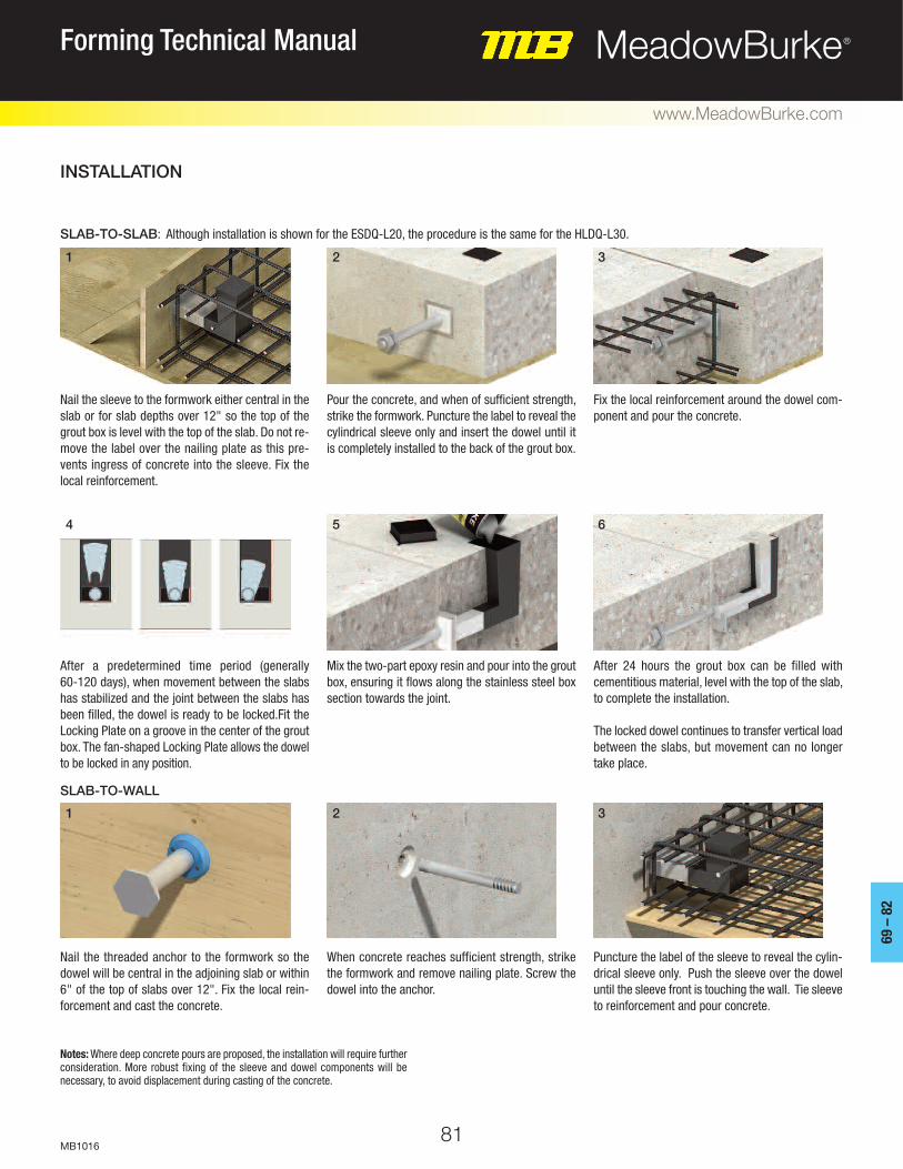
81
INSTALLATION
69 –
82
MeadowBurke®Forming Technical Manual
www.MeadowBurke.com
MB1016
SLAB-TO-SLAB: Although installation is shown for the ESDQ-L20, the procedure is the same for the HLDQ-L30.
SLAB-TO-WALL
Notes: Where deep concrete pours are proposed, the installation will require furtherconsideration. More robust fixing of the sleeve and dowel components will be necessary, to avoid displacement during casting of the concrete.
Nail the sleeve to the formwork either central in theslab or for slab depths over 12" so the top of thegrout box is level with the top of the slab. Do not re-move the label over the nailing plate as this pre-vents ingress of concrete into the sleeve. Fix thelocal reinforcement.
Pour the concrete, and when of sufficient strength,strike the formwork. Puncture the label to reveal thecylindrical sleeve only and insert the dowel until itis completely installed to the back of the grout box.
Fix the local reinforcement around the dowel com-ponent and pour the concrete.
After a predetermined time period (generally 60-120 days), when movement between the slabshas stabilized and the joint between the slabs hasbeen filled, the dowel is ready to be locked.Fit theLocking Plate on a groove in the center of the groutbox. The fan-shaped Locking Plate allows the dowelto be locked in any position.
Mix the two-part epoxy resin and pour into the groutbox, ensuring it flows along the stainless steel boxsection towards the joint.
After 24 hours the grout box can be filled with cementitious material, level with the top of the slab,to complete the installation.
The locked dowel continues to transfer vertical loadbetween the slabs, but movement can no longertake place.
Nail the threaded anchor to the formwork so thedowel will be central in the adjoining slab or within6" of the top of slabs over 12". Fix the local rein-forcement and cast the concrete.
When concrete reaches sufficient strength, strikethe formwork and remove nailing plate. Screw thedowel into the anchor.
Puncture the label of the sleeve to reveal the cylin-drical sleeve only. Push the sleeve over the doweluntil the sleeve front is touching the wall. Tie sleeveto reinforcement and pour concrete.
2 3
64 5
32
1
1

Medium and Heavy Forming Miscellaneous
83
83 –
88
MeadowBurke®Forming Technical Manual
www.MeadowBurke.com
MB1018

84
MeadowBurke®Forming Technical Manual
www.MeadowBurke.com
MB1018
TIE HOLE PLUGS
Tie Hole Plugs are plastic plugs available in 9/16" and 13/16" diameters used to tem-
porarily fill holes in the formwork plywood.
To Order, Specify: quantity, type and diameter.
CP-2 COIL SETTING PLUG – PLASTIC
The CP-2 Coil Setting Plugs are available in 1/2", 3/4" and 1" diameters. They are effec-
tively used to set inserts in the form by nailing the plug to the form face and then
threading the coil insert onto the plug. The reusable plugs are easily removed from the
concrete after the form has been stripped. The Coil Setting Plug can also be used as a
temporary cap when another pour will be made at a later time.
CS-8 & CS-9 STEEL STAKES
The CS-8 and CS-9 are fabricated from quality steel round bar. They are available in
3/4" and 7/8" diameters, with or without nail holes, in the standard lengths of 18", 24",
30", 36", 42" and 48".
1/2"
3/4"
1"
Diameter
1/2"
3/4"
3/4"
Set Back
2-1/4"
3-1/4"
4-3/4"
Length
1-3/8"
2"
2"
A
CP-2 COIL SETTING PLUG DATA
CS-8
CS-9
Type
3/4"
7/8"
Diameter
CS-8 & CS-9 STEEL STAKE DATA
Safe working load is based on an approximate 2:1 safety factor. To Order, Specify: quantity, type and diameter.
A
Length
Set Back
To Order, Specify: quantity, type and diameter.

85
83 –
88
MeadowBurke®Forming Technical Manual
www.MeadowBurke.com
MB1018
HF-12 SNAP TIE HANGER - STANDARD
HF-14 SNAP TIE HANGER - HEAVY
The HF-12 & HF-14 Snap Tie Hangers are manufactured the same as normal snap ties and are then bent
to fit specific beam dimensions. Metal washers or plastic spreader cones space the soffit in proper posi-
tion. The hangers are furnished with a 1/2" breakback to allow the tie to be broken back from the face
of the concrete. Snap Tie hangers are available in standard and heavy versions for use with light 2x4
type of forming.
HF-16 WIRE BEAM SADDLE WITH PLATE HANGER
The HF-16 Wire Beam Saddle Hangers are fixed-length hangers suitable for light slab construction. They
are fabricated to specific job requirements and are available in standard and heavy versions for 2x4 or 2x6
joist lumber. These hangers are designed for use with lumber joist material and should not be used to sup-
port metal joist applications.
HF-18 COIL SADDLE HANGER
The HF-18 Coil Saddle Hanger is manufactured the same as a typical Coil Tie and then bent to the dimen-
sions of a specific beam width. Coil Saddle Hangers are available in 1/2", 3/4" and 1" diameters and in
lengths per job requirement. Minimum coil penetration warning on Page 45 applies.
TYPE HF-12-Std. HF-14-Hvy.
SWL in (lbs) 1,500/side 2,000/side
HF-12 & HF-14 SNAP TIE HANGER DATA
TYPE HF-16-Std. HF-16-Hvy.
WIRE #7 #4
SWL in (lbs) 1,000/side 1,500/side
HF-16 WIRE BEAM SADDLE DATA
Safe working load is based on an approximate 2:1 safety factor. To Order, Specify: quantity, type, beam width, beam depth, concrete cover, and lumber and wedge dimension.
Safe working load is based on an approximate 2:1 safety factor. To Order, Specify: quantity, type, standard or heavy, beam width, total drop and joist material.
Coil Bolt Dia. 1/2" 3/4" 1"
SWL in (lbs) 2,250/side 5,625/side 7,500/side
HF-18 COIL SADDLE HANGER DATA
Safe working loads based on an approximate 2:1 safety factor. To Order, Specify: quantity, type, standard or heavy, beam width, total drop and joist material.
F
F
D
E
D
F
D
J
E = Lumber & Wedge
D = Beam Depth + Concrete Cover
Not recommended for use on horizontal steel shoring - no warranty or guaran-tees apply.
TYPE HF-18 HF-18 HF-18

86
MeadowBurke®Forming Technical Manual
www.MeadowBurke.com
MB1018
CX-32 SCREED CHAIR – ADJUSTABLE
CH-37 PIPE HOLDER
The CX-32 Screed Chair – Adjustable, is available in 1/2" diameter x (2-1/2", 3-1/2", 5-1/2") heights
for slabs from 4" up to 11-1/2" and a 3/4" diameter x 5-1/2" height for slabs from 9-1/2" up to 16".
The CH-37 Pipe Holder, is available in 1/2" or 3/4" diameter for use with screed chairs to obtain proper
slab heights. To adjust the chair and pipe holder height for grade, hold the pipe holder stationary while
turning the chair up or down.
CX-31 SCREED CHAIR – ADJUSTABLE W/BASE
The CX-31 Screed Chair – Adjustable with Sand Plates, is the same as the CX-32 but with Sand Plates
welded to the bottom for use on sand, fill dirt, vapor barrier, or other soft supporting materials. Use
with CH-37 Pipe Holder. Table above also applies to the CX-31 Screed Chair.
To Order, Specify: quantity, type, number, diameter, height or length.
CX-33 SCREED CHAIR – METAL DECK
The CX-33 Screed Chair – Metal Deck, is a modified CX-32 flattened to fit low profile and span
across steel deck corrigations. Available in both 1/2" and 3/4" diameter.
To Order, Specify: quantity, type, diameter, height or length .
CX-32 SCREED CHAIR & CH-37 PIPE HOLDER DATACH-37 Pipe #
CX-32 Chair #
Slab Thickness
Minimum0
1
2
3
4
5
1
1
2
3
4
4
3-1/2"
4-1/2"
5-1/2"
7-1/2"
9-1/2"
13-1/2"
4-1/2"
5-1/2"
7-1/2"
11-1/2"
13-1/2"
16-1/2"
Maximum
All slab heights shown are based on 1" ID pipe (1-1/16" OD) Warning: Products shown above are not intended to support mechanical screeding machines. For manual screed operations only. To Order, Specify: quantity, type, number, diameter, height or length.
CH-37
CX-32
1/2" x 2-1/2"
1/2" x 2-1/2"
1/2" x 3-1/2"
1/2" x 5-1/2"
3/4" x 5-1/2"
3/4" x 5-1/2"
1/2" x 1-1/2"
1/2" x 3"
1/2" x 4"
1/2" x 6"
3/4" x 8"
3/4" x 12"
Screed Chair Size
Pipe Holder Size
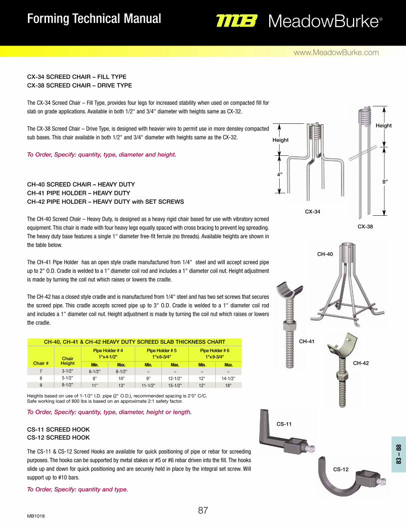
87
87
83 –
88
MeadowBurke®Forming Technical Manual
www.MeadowBurke.com
MB1018
Heights based on use of 1-1/2" I.D. pipe (2" O.D.), recommended spacing is 2'0" C/C. Safe working load of 800 lbs is based on an approximate 2:1 safety factor. To Order, Specify: quantity, type, diameter, height or length.
CX-34 SCREED CHAIR – FILL TYPE CX-38 SCREED CHAIR – DRIVE TYPE The CX-34 Screed Chair – Fill Type, provides four legs for increased stability when used on compacted fill for slab on grade applications. Available in both 1/2" and 3/4" diameter with heights same as CX-32. The CX-38 Screed Chair – Drive Type, is designed with heavier wire to permit use in more densley compacted sub bases. This chair available in both 1/2" and 3/4" diameter with heights same as the CX-32. To Order, Specify: quantity, type, diameter and height.
CH-40 SCREED CHAIR – HEAVY DUTY CH-41 PIPE HOLDER – HEAVY DUTY CH-42 PIPE HOLDER – HEAVY DUTY with SET SCREWS The CH-40 Screed Chair – Heavy Duty, is designed as a heavy rigid chair based for use with vibratory screed equipment. This chair is made with four heavy legs equally spaced with cross bracing to prevent leg spreading. The heavy duty base features a single 1" diameter free-fit ferrule (no threads). Available heights are shown in the table below. The CH-41 Pipe Holder has an open style cradle manufactured from 1/4" steel and will accept screed pipe up to 2" O.D. Cradle is welded to a 1” diameter coil rod and includes a 1" diameter coil nut. Height adjustment is made by turning the coil nut which raises or lowers the cradle. The CH-42 has a closed style cradle and is manufactured from 1/4" steel and has two set screws that secures the screed pipe. This cradle accepts screed pipe up to 3" O.D. Cradle is welded to a 1" diameter coil rod and includes a 1" diameter coil nut. Height adjustment is made by turning the coil nut which raises or lowers the cradle.
CS-11 SCREED HOOK CS-12 SCREED HOOK The CS-11 & CS-12 Screed Hooks are available for quick positioning of pipe or rebar for screeding purposes. The hooks can be supported by metal stakes or #5 or #6 rebar driven into the fill. The hooks slide up and down for quick positioning and are securely held in place by the integral set screw. Will support up to #10 bars. To Order, Specify: quantity and type.
Chair #
7 8 9
Chair Height
3-1/2" 5-1/2" 8-1/2"
6-1/2" 8" 11"
8-1/2" 10" 13"
– 9"
11-1/2"
– 12-1/2" 15-1/2"
– 12" 12"
– 14-1/2"
18"
CH-40, CH-41 & CH-42 HEAVY DUTY SCREED SLAB THICKNESS CHART
Pipe Holder # 4 1"x4-1/2"
Min. Max.
Pipe Holder # 5 1"x6-3/4"
Min. Max.
Pipe Holder # 6 1"x9-3/4"
Min. Max.
CS-11
CH-41
CH-42
CH-40
CX-34
CX-38
CS-12
8”
Height
4”
Height

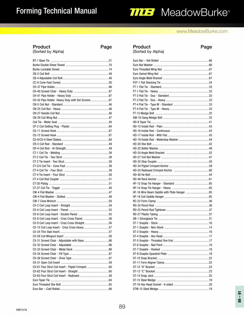
89
89 –
91
MeadowBurke®Forming Technical Manual
www.MeadowBurke.com
MB1018
Product Page (Sorted by Alpha) Euro Bar – Hot Rolled ................................................................66 Euro Nut Washer ........................................................................66 Euro Threaded Wing Nut ............................................................67 Euro Swivel Wing Nut ................................................................67 Euro Angle Weld Bracket ............................................................67 FST-1 Flat Stacking Tie ..............................................................34 FT-1 Flat Tie - Standard..............................................................33 FT-1 Flat Tie - Heavy ..................................................................33 FT-3 Flat Tie - Duo - Standard ....................................................33 FT-3 Flat Tie - Duo - Heavy ........................................................33 FT-4 Flat Tie - Type M - Standard ..............................................33 FT-4 Flat Tie - Type M - Heavy....................................................33 FT-15 Wedge Bolt ......................................................................32 GW-16 Gang Wedge Bolt ............................................................32 HD-9 Taper Tie............................................................................41 HD-15 Inside Rod - Plain ............................................................43 HD-16 Inside Rod - Continuous ..................................................43 HD-17 Inside Rod - With Flat ......................................................43 HD-19 Inside Rod - Waterstop Washer........................................44 HD-20 She Bolt ..........................................................................42 HD-22 Batter Washer..................................................................48 HD-24 Angle Weld Bracket ........................................................52 HD-27 Coil Nut Washer ..............................................................47 HD-32 Stop Coupler....................................................................50 HD-34 Pigtail Crimped Anchor ....................................................59 HD-35 Radiused Crimped Anchor ..............................................60 HD-40 He Bolt ............................................................................44 HD-46 Rock Anchor ....................................................................61 HF-12 Snap Tie Hanger - Standard ............................................85 HF-14 Snap Tie Hanger - Heavy ................................................85 HF-16 Wire Beam Saddle with Plate Hanger ..............................85 HF-18 Coil Saddle Hanger ..........................................................85 RC-22 Form Clamp ....................................................................36 RD-24 Pencil Rod ......................................................................36 RD-25 Pencil Rod Tightener ........................................................37 RD-27 Plastic Tubing ..................................................................37 SB-1 Strongback Tie ..................................................................31 ST-1 Snaptie - Stock ..................................................................16 ST-1 Snaptie - Non-Stock ..........................................................14 ST-3 Snaptie - Heavy..................................................................16 ST-4 Snaptie - Hex Head ............................................................17 ST-5 Snaptie - Threaded One End ..............................................17 ST-6 Snaptie - Nail Point ............................................................18 ST-7 Snaptie - Hooked ..............................................................18 ST-9 Snaptie-Spandrel Plate ......................................................18 ST-10 Snap Bracket....................................................................22 ST-11 Form Aligner Clamp..........................................................22 ST-12 “A” Bracket ......................................................................23 ST-13 “C” Bracket ......................................................................23 ST-14 Snap Jack ........................................................................25 ST-15 Steel Wedge ....................................................................19 ST-16 Hex Head Socket - 6-sided ..............................................20 STW-15 Steel Wedge ..................................................................19
Product Page (Sorted by Alpha) BT-1 Base Tie ............................................................................31 Burke Double Shear Dowel ........................................................70 Burke Lockable Dowel ................................................................74 CB-2 Coil Bolt ............................................................................48 CB-4 Adjustable Coil Bolt ............................................................48 CC-6 Cone-Fast Cones) ..............................................................50 CH-37 Pipe Holder ......................................................................86 CH-40 Screed Chair - Heavy Duty ..............................................87 CH-41 Pipe Holder - Heavy Duty ................................................87 CH-42 Pipe Holder -Heavy Duty with Set Screws........................87 CN-5 Coil Nut - Standard............................................................46 CN-25 Coil Nut - Heavy ..............................................................46 CN-27 Handle Coil Nut................................................................46 CN-29 Coil Wing Nut ..................................................................47 Coil Tie - Water Seal ..................................................................40 CP-2 Coil Setting Plug - Plastic ..................................................84 CS-11 Screed Hook ....................................................................87 CS-12 Screed Hook ....................................................................87 CS-8/CS-9 Steel Stakes..............................................................84 CR-3 Coil Rod - Standard ..........................................................49 CR-4 Coil Rod - Hi-Strength........................................................49 CT-1 Coil Tie - Welding ..............................................................38 CT-2 Coil Tie - Two Strut ............................................................38 CT-2 Tie Insert - Two Strut ..........................................................58 CT-2/4 Coil Tie - Cone-Fast ........................................................39 CT-4 Coil Tie - Four Strut ..........................................................39 CT-4 Tie Insert - Four Strut ........................................................58 CT-4 Coil Rod Coupler ................................................................51 CT-20 Plylag ..............................................................................51 CT-37 Coil Tie - Toggle ..............................................................40 CW-4 Flat Washer ......................................................................47 CW-4 Flat Washer - Slotted ........................................................48 CW-7 Cone Wrench ....................................................................50 CX-2 Coil Loop Insert - Straight ..................................................54 CX-4 Coil Loop Insert - Flared ....................................................55 CX-6 Coil Loop Insert - Double Flared ........................................55 CX-8 Coil Loop Insert - Criss Cross Flared. ................................56 CX-9 Coil Loop Insert - Criss Cross Straight................................56 CX-15 Coil Loop Insert - Criss Cross Heavy ................................57 CX-24 Thin Slab Insert ................................................................57 CX-28 Coil Wingnut Insert ..........................................................58 CX-31 Screed Chair - Adjustable with Base ................................86 CX-32 Screed Chair - Adjustable ................................................86 CX-33 Screed Chair - Metal Deck ..............................................86 CX-34 Screed Chair - Fill Type ....................................................87 CX-38 Screed Chair - Drive Type ................................................87 CX-51 Open Coil Insert ..............................................................59 CX-61 Four Strut Coil Insert - Pigtail Crimped ............................60 CX-62 Four Strut Coil Insert - Straight ........................................60 CX-63 Four Strut Coil Insert - Radiused ......................................58 Euro Taper Tie ............................................................................64 Euro Threaded She Bolt ..............................................................65 Euro Bar – Cold Rolled................................................................66

90
MeadowBurke®Forming Technical Manual
www.MeadowBurke.com
MB1018
Product Page (Sorted by Alpha) ST-17 Residential Snaptie ..........................................................20 ST-18 Residential Snaptie ..........................................................20 ST-19 Panel Lock Tie ..................................................................36 ST-21 Snaptie Wrench ................................................................19 ST-23 Loop Tie - Standard..........................................................30 ST-24 Loop Tie - Heavy ..............................................................30 ST-25 Gang Tie - Standard ........................................................30 ST-26 Gang Tie - Heavy..............................................................30 ST-27 Form Aligner Braces ........................................................24 ST-28 Form Aligner Braces ........................................................24 ST-29 Loop Tie - Plastic Cone ....................................................30 ST-30 Loop Tie - Plastic Cone H/D..............................................30 ST-32 Masonry Beam Clamp - Standard ....................................28 ST-33 Masonry Beam Clamp - Heavy with Brace ......................28 ST-35 Quick Cleat - Stamped ....................................................34 ST-36 Quick Cleat - Wire ............................................................34 Tie Hole Plugs ............................................................................84 WT-1 Waler Tie ..........................................................................31 WH-1 Waler Holder ....................................................................32
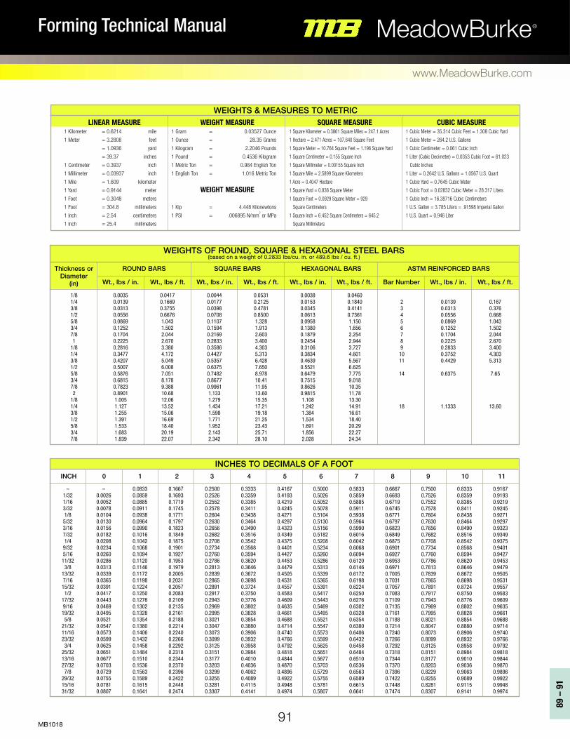
91
89 –
91
MeadowBurke®Forming Technical Manual
www.MeadowBurke.com
MB1018
LINEAR MEASURE 1 Kilometer = 0.6214 mile
1 Meter = 3.2808 feet
= 1.0936 yard
= 39.37 inches
1 Centimeter = 0.3937 inch
1 Millimeter = 0.03937 inch
1 Mile = 1.609 kilometer
1 Yard = 0.9144 meter
1 Foot = 0.3048 meters
1 Foot = 304.8 millimeters
1 Inch = 2.54 centimeters
1 Inch = 25.4 millimeters
WEIGHT MEASURE 1 Gram = 0.03527 Ounce
1 Ounce = 28.35 Grams
1 Kilogram = 2.2046 Pounds
1 Pound = 0.4536 Kilogram
1 Metric Ton = 0.984 English Ton
1 English Ton = 1.016 Metric Ton
WEIGHT MEASURE
1 Kip = 4.448 Kilonewtons
1 PSI = .006895 N/mm2 or MPa
SQUARE MEASURE 1 Square Kilometer = 0.3861 Square Miles = 247.1 Acres
1 Hectare = 2.471 Acres = 107,640 Square Feet
1 Square Meter = 10.764 Square Feet = 1.196 Square Yard
1 Square Centimeter = 0.155 Square Inch
1 Square Millimeter = 0.00155 Square Inch
1 Square Mile = 2.5899 Square Kilometers
1 Acre = 0.4047 Hectare
1 Square Yard = 0.836 Square Meter
1 Square Foot = 0.0929 Square Meter = 929
Square Centimeters
1 Square Inch = 6.452 Square Centimeters = 645.2
Square Millimeters
CUBIC MEASURE 1 Cubic Meter = 35.314 Cubic Feet = 1.308 Cubic Yard
1 Cubic Meter = 264.2 U.S. Gallons
1 Cubic Centimeter = 0.061 Cubic Inch
1 Liter (Cubic Decimeter) = 0.0353 Cubic Foot = 61.023
Cubic Inches
1 Liter = 0.2642 U.S. Gallons = 1.0567 U.S. Quart
1 Cubic Yard = 0.7645 Cubic Meter
1 Cubic Foot = 0.02832 Cubic Meter = 28.317 Liters
1 Cubic Inch = 16.38716 Cubic Centimeters
1 U.S. Gallon = 3.785 Liters = .91598 Imperial Gallon
1 U.S. Quart = 0.946 Liter
WEIGHTS & MEASURES TO METRIC
Thickness or Diameter
(in) Wt., lbs / in. Wt., lbs / in. Wt., lbs / in. Wt., lbs / in.Wt., lbs / ft. Wt., lbs / ft. Wt., lbs / ft. Bar Number Wt., lbs / ft.
ROUND BARS SQUARE BARS HEXAGONAL BARS ASTM REINFORCED BARS
0.0035 0.0139 0.0313 0.0556 0.0869 0.1252 0.1704 0.2225 0.2816 0.3477 0.4207 0.5007 0.5876 0.6815 0.7823 0.8901 1.005 1.127 1.255 1.391 1.533 1.683 1.839
0.0417 0.1669 0.3755 0.6676 1.043 1.502 2.044 2.670 3.380 4.172 5.049 6.008 7.051 8.178 9.388 10.68 12.06 13.52 15.06 16.69 18.40 20.19 22.07
0.0044 0.0177 0.0398 0.0708 0.1107 0.1594 0.2169 0.2833 0.3586 0.4427 0.5357 0.6375 0.7482 0.8677 0.9961 1.133 1.279 1.434 1.598 1.771 1.952 2.143 2.342
0.0531 0.2125 0.4781 0.8500 1.328 1.913 2.603 3.400 4.303 5.313 6.428 7.650 8.978 10.41 11.95 13.60 15.35 17.21 19.18 21.25 23.43 25.71 28.10
0.0038 0.0153 0.0345 0.0613 0.0958 0.1380 0.1879 0.2454 0.3106 0.3834 0.4639 0.5521 0.6479 0.7515 0.8626 0.9815 1.108 1.242 1.384 1.534 1.691 1.856 2.028
0.0460 0.1840 0.4141 0.7361 1.150 1.656 2.254 2.944 3.727 4.601 5.567 6.625 7.775 9.018 10.35 11.78 13.30 14.91 16.61 18.40 20.29 22.27 24.34
2 3 4 5 6 7 8 9
10 11
14
18
0.0139 0.0313 0.0556 0.0869 0.1252 0.1704 0.2225 0.2833 0.3752 0.4429
0.6375
1.1333
0.167 0.376 0.668 1.043 1.502 2.044 2.670 3.400 4.303 5.313
7.65
13.60
WEIGHTS OF ROUND, SQUARE & HEXAGONAL STEEL BARS (based on a weight of 0.2833 lbs/cu. in. or 489.6 lbs / cu. ft.)
INCH 0 1 2 3 4 5 6 7 8 9 10 11
– 1/32 1/16 3/32 1/8
5/32 3/16 7/32 1/4
9/32 5/16 11/32 3/8
13/32 7/16 15/32 1/2
17/32 9/16 19/32 5/8
21/32 11/16 23/32 3/4
25/32 13/16 27/32 7/8
29/32 15/16 31/32
– 0.0026 0.0052 0.0078 0.0104 0.0130 0.0156 0.0182 0.0208 0.0234 0.0260 0.0286 0.0313 0.0339 0.0365 0.0391 0.0417 0.0443 0.0469 0.0495 0.0521 0.0547 0.0573 0.0599 0.0625 0.0651 0.0677 0.0703 0.0729 0.0755 0.0781 0.0807
0.0833 0.0859 0.0885 0.0911 0.0938 0.0964 0.0990 0.1016 0.1042 0.1068 0.1094 0.1120 0.1146 0.1172 0.1198 0.1224 0.1250 0.1276 0.1302 0.1328 0.1354 0.1380 0.1406 0.1432 0.1458 0.1484 0.1510 0.1536 0.1563 0.1589 0.1615 0.1641
0.1667 0.1693 0.1719 0.1745 0.1771 0.1797 0.1823 0.1849 0.1875 0.1901 0.1927 0.1953 0.1979 0.2005 0.2031 0.2057 0.2083 0.2109 0.2135 0.2161 0.2188 0.2214 0.2240 0.2266 0.2292 0.2318 0.2344 0.2370 0.2396 0.2422 0.2448 0.2474
0.2500 0.2526 0.2552 0.2578 0.2604 0.2630 0.2656 0.2682 0.2708 0.2734 0.2760 0.2786 0.2813 0.2839 0.2865 0.2891 0.2917 0.2943 0.2969 0.2995 0.3021 0.3047 0.3073 0.3099 0.3125 0.3151 0.3177 0.3203 0.3299 0.3255 0.3281 0.3307
0.3333 0.3359 0.3385 0.3411 0.3438 0.3464 0.3490 0.3516 0.3542 0.3568 0.3594 0.3620 0.3646 0.3672 0.3698 0.3724 0.3750 0.3776 0.3802 0.3828 0.3854 0.3880 0.3906 0.3932 0.3958 0.3984 0.4010 0.4036 0.4062 0.4089 0.4115 0.4141
0.4167 0.4193 0.4219 0.4245 0.4271 0.4297 0.4323 0.4349 0.4375 0.4401 0.4427 0.4453 0.4479 0.4505 0.4531 0.4557 0.4583 0.4609 0.4635 0.4661 0.4688 0.4714 0.4740 0.4766 0.4792 0.4818 0.4844 0.4870 0.4896 0.4922 0.4948 0.4974
0.5000 0.5026 0.5052 0.5078 0.5104 0.5130 0.5156 0.5182 0.5208 0.5234 0.5260 0.5286 0.5313 0.5339 0.5365 0.5391 0.5417 0.5443 0.5469 0.5495 0.5521 0.5547 0.5573 0.5599 0.5625 0.5651 0.5677 0.5703 0.5729 0.5755 0.5781 0.5807
0.5833 0.5859 0.5885 0.5911 0.5938 0.5964 0.5990 0.6016 0.6042 0.6068 0.6094 0.6120 0.6146 0.6172 0.6198 0.6224 0.6250 0.6276 0.6302 0.6328 0.6354 0.6380 0.6406 0.6432 0.6458 0.6484 0.6510 0.6536 0.6563 0.6589 0.6615 0.6641
0.6667 0.6693 0.6719 0.6745 0.6771 0.6797 0.6823 0.6849 0.6875 0.6901 0.6927 0.6953 0.6971 0.7005 0.7031 0.7057 0.7083 0.7109 0.7135 0.7161 0.7188 0.7214 0.7240 0.7266 0.7292 0.7318 0.7344 0.7370 0.7396 0.7422 0.7448 0.7474
0.7500 0.7526 0.7552 0.7578 0.7604 0.7630 0.7656 0.7682 0.7708 0.7734 0.7760 0.7786 0.7813 0.7839 0.7865 0.7891 0.7917 0.7943 0.7969 0.7995 0.8021 0.8047 0.8073 0.8099 0.8125 0.8151 0.8177 0.8203 0.8229 0.8255 0.8281 0.8307
0.8333 0.8359 0.8385 0.8411 0.8438 0.8464 0.8490 0.8516 0.8542 0.8568 0.8594 0.8620 0.8646 0.8672 0.8698 0.8724 0.8750 0.8776 0.8802 0.8828 0.8854 0.8880 0.8906 0.8932 0.8958 0.8984 0.9010 0.9036 0.9063 0.9089 0.9115 0.9141
0.9167 0.9193 0.9219 0.9245 0.9271 0.9297 0.9323 0.9349 0.9375 0.9401 0.9427 0.9453 0.9479 0.9505 0.9531 0.9557 0.9583 0.9609 0.9635 0.9661 0.9688 0.9714 0.9740 0.9766 0.9792 0.9818 0.9844 0.9870 0.9896 0.9922 0.9948 0.9974
INCHES TO DECIMALS OF A FOOT
1/8 1/4 3/8 1/2 5/8 3/4 7/8 1
1/8 1/4 3/8 1/2 5/8 3/4 7/8 2
1/8 1/4 3/8 1/2 5/8 3/4 7/8
Innovating Concrete Constructionwww.MeadowBurke.com
TAMPA 6467 S. Falkenburg Road Riverview, FL 33578 (877) 518-7665 ENGINEERING (813) 280-8900
ARIZONA PHOENIX 501 N. 37th Dr. Suite 106-109 Phoenix, AZ 85009 (602) 455-0717 (800) 817-9698 FAX: (602) 455-0719 CALIFORNIA ANAHEIM 3611 East La Palma Ave. Suite A Anaheim, CA 92806 (714) 632-6651 (800) 804-6565 FAX: (714) 632-9412 FLORIDA TAMPA 6467 S Falkenburg Rd Riverview, FL 33578 (813) 248-1945 (800) 282-7213 FAX: (877) 568-8296 GEORGIA ATLANTA 3080 N. Lanier Parkway Decatur, GA 30034 (404) 378-3175 (800) 241-5662 FAX: (404) 373-1804
ILLINOIS CHICAGO (513) 942-0268 (866) 773-0536 FAX: (877) 311-0452 NEW JERSEY PALISADES PARK 269 Commercial Ave. Palisades Park, NJ 07650 (201) 242-8989 (800) 207-7778 FAX: (201) 242-8860 NORTH CAROLINA CHARLOTTE 3401-A Woodpark Blvd. Charlotte NC 28206 (704) 376-9192 (800) 376-9192 FAX: (855) 760-3966 OREGON PORTLAND 155 SE Hazel Dell Way Canby, OR 97013 (888) 232-9991 FAX: (503) 266-8934
PENNSYLVANIA HAZLETON 565 Oak Ridge Road Hazle Township, PA 18202 540-376-3287 (800) 550-0060 TEXAS SAN ANTONIO 8521 FM 1976 Converse TX 78109 (210) 658-4671 (800) 323-6896 FAX: (210) 658-8312 TEXAS FT. WORTH 7000 Will Rogers Blvd. Ft. Worth, TX 76140 (817) 293-9641 (800) 993-9641 FAX: (817) 293-8081 WASHINGTON AUBURN 3416 B Street, Suite B Auburn, WA 98001 (877) 289-2113 FAX: (877) 439-1965
SERVICE & DISTRIBUTION CENTERS CORPORATE
MB0319 MeadowBurke®