boss titolo 32 bold - carel
TRANSCRIPT

Sottotitolo 32 ligthsottotitolo
Titolo 32 bold
Connected
bossThe complete range for mobile-ready local supervision

with built-in Wi-Fi, accessible from all mobile devices
Energy saving & system optimisation Algorithms for analysis and comparison, developed exploiting CAREL’s experience, to facilitate and guide users in optimising energy consumption.
Secure data & browsing HTTPS protocol for secure data transfer over the web from boss to an external device.Customised operating system to guarantee system reliability.
Intuitive & customisable interface All the information is available to the user in just a few simple clicks, including system configuration and device management.
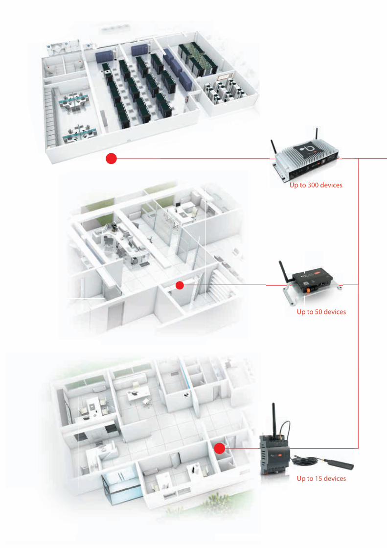
Supervisors for small,medium and large sites
• Completely browsable from mobile devices, from commissioning to daily access for system maintenance;
• Built-in Wi-Fi to create a network and allow the supervisor to be accessed from the user’s devices without requiring other network infrastructure.
range
• Built-in 4G modem on boss-micro for sending emails / instant messages / SMS without needing to use the building’s IT infrastructure to connect to the Internet

boss always in your pocketResponsive web pages offer the possibility to access all boss pages for both programming and everyday operations using mobile devices. The graphics automatically to the device they are displayed on (computers with different screen resolutions, tablets, smartphones), minimising the need for the user to resize the pages and scroll the contents.
centralised managementboss permits automatic data and alarm synchronisation with RemotePRO, so as to keep the situation on all connected systems under control from just one interface. Centralised system management also increases reliability, through alarm analysis and scheduling of service. It also allows increased energy efficiency by comparing energy consumption and performance between the different sites and identifying possible cost reduction actions.
remote serviceAccess to typical operating system functions, such as printer driver installation, copying files, etc. is also available via a web interface, another first for a supervisory system. This means that remote service operations can be performed by authorised personnel without needing to travel on site, as is required with other supervisory systems.

Bacnet™/Modbus®/SNMP
BMS
Bac
net™
/Mod
bus®/SNMP
Bac
net™
/Mod
bus®/SNMP
Bacnet™/M
odbu
s®/SNMP
Bacnet™/M
odbus®/SNMP
Bac
net™
/Mod
bus®/SNMP
GTW0000WT0
c.pCo
ir33
GTW0000WT0
c.pCo
ir33
Management of Modbus®, BACnet™ and SNMP protocols for third-party device integration.
Protocols and connectivity
Third-party device integrationManagement of these three protocols offers high potential for integration with third-party devices. The SNMP manager and BACnet™ Client protocols, available both in MS/TP and IP modes, as well as the Modbus® protocol in RS485 and TCP modes, offer the possibility to interact
Integration into BMS systemsIn addition to Client mode, the SNMP, BACnet™ and Modbus® protocols are also available on boss in Server mode, the BACnet™ protocol is also available on boss in TCP/IP Slave mode, allowing boss to be integrated into a higher-level BMS, sharing the values of interest for overall building management (e.g. unit status, alarm status, ON/OFF controls,...)
Wireless field connectivityIf Modbus RTU devices cannot be connected directly to the boss/boss-mini RS485 network due to installation constraints, these can be integrated into the boss system via its Wi-Fi network, using the WiFi-Modbus gateways (GTW0000WT0). Nonetheless, when a wired connection is available, this is the preferred option due to its reliability.
with the widest range of devices on the HVAC/R market

System optimisation functions
DEW POINT BROADCASTShare the dew point
This is used to optimise activation of the anti-sweat heaters on the refrigeration units connected to boss, and consequently reduce
power consumption. Connected to a room temperature and humidity probe, boss calculates the dew point in the area and sends the value to the entire network of connected units.
LOGICAL DEVICE/GROUNDLogical devices & logical variables
This is used to create new “virtual” variables and devices on boss, and then manage these as if they were real variables or devices, created based
on physical variables on the existing network devices.
GEO - LIGHTINGOptimised management of lights based on outside light
This is used to optimise switch-on and switch-off of outdoor lights based on site latitude and longitude, thus
knowing the time when the sun rises and sets.
ENERGYConsumption control and management
Allows users to monitor system energy consumption using graphs and reports, and then implement actions aimed at reducing waste or
fixing any faults highlighted.
KPIPerformance index
Allows users to analyse the thermodynamic behaviour of the individual units connected to boss, defining for each,
or for groups of units, the minimum and maximum operating thresholds for different variables, creating dashboards to identify which units are operating outside of the optimum conditions.
SAFE RESTORESafe compressor rack restart
This is used to manage safe and optimum compressor rack restart following a fault, in the event of specific compressor rack conditions putting
all the connected refrigeration units in safety mode.
ALGORITHM PROCustomised logic
This is used to create additional customised logic using the Java programming language, so as to increase interaction between boss and the
connected devices.
SMART HIGH PURGEOptimised free cooling on HVAC units
The air-conditioning system can be started before sunrise using calculations based on system enthalpy (inside and outside), so as to fully exploit free
cooling.
FLOATING SUCTIONOptimised suction pressure
This is used to optimise - in real time - the compressor rack working set point, thus reducing power consumption,
by analysing the duty cycle of the connected cabinets. Based on cabinet cooling demand, the plug-in increases or decreases the compressor rack set point.
PARAMETER CONTROLParameter control
This is used to monitor all fundamental parameter setting actions on the units connected to the supervisor, for example the set point,
performed either using boss or directly on the unit, and then activate restore logic, sending alerts when such occur.
HVAC SMART STARTOptimised air-conditioning ON/OFF
This is used to optimise activation, shutdown and set point change on HVAC units based on the ambient information acquired by boss, such as inside
and outside temperature, system inertia, occupancy and air quality.
USAGE BALANCEROptimised unit capacity managementBy reading the room temperature and
humidity probes, the average values can be calculated so as to determine the actual capacity required and optimise and balance the operating cycles of
the various units installed (**)

Up to 300 devices
Up to 50 devices
Up to 15 devices

Optimisation of retail systemsIn addition to all the functions of a standard supervisor, boss all includes functions for
managing refrigeration units and interaction between units, meaning not only is the
system controlled, but also optimised in terms of thermodynamic performance and
energy consumption.
CAREL’s extensive and in-depth knowledge of these applications has also led to the
development of user interfaces that are configured based on the type of user (i.e.
installer, maintenance personnel, system manager) and the type of use, so as ensure
simpler and faster commissioning.
Refrigeration applications
Up to 300 devices
Up to 50 devices
Up to 15 devices

Optimisation of HVAC systemsThe high level of configurability, the possibility to customise maps and the availability
of BACnet, SNMP and Modbus standard protocols for communication over the
Ethernet network, make boss suitable for numerous HVAC applications.
The supervisor can also interface with other BMS systems, for example in large
buildings where the main BMS manages those systems that are not included among
the functions handled by boss (security, fire safety,…).
In this case, boss manages the HVAC systems, providing specific data that create
added value for the end customer, and then sharing with the main BMS only
the information needed to understand system status.
Air-conditioning applications

With the c.web tool, system status and the main variables relating to each controller can be represented using customised graphics. Indeed c.web offers several powerful features, such as the creation of vectorial images that can adapt to all screen sizes on both desktop and mobile devices without losing resolution, the possibility to develop customised animated widgets in just a few clicks, and the reusability of graphic libraries developed for one project inside another.
User interfaces that can be customised according to the way in which information is managed by different users
Customised graphics

boss boss mini boss micro
No moving mechanical devices for heat dissipation, thus allowing installation in various different equipment rooms and other spaces, allowing installation even in unfavourable technical environments.
The same hardware is suitable for all applications
Desktop
Wall-mounted
DIN rail

VGAFIELD LAN C NO NC C NO NC C NO NC POWER12 Vdc
INGN
D
1
2
3
4
1 2 321
121110 13 14 19 818
8
9
16 1715
12 2
31
2
31
2
1
21
3
4 6 75
2
340
145
77
100,94 100,94202
120,20
453
89,43
94,50
120,20
100,94
120,20
boss mini
boss
Dimensions and key
Key1. ON/OFF status LED2. Alarm status LED3. Digital input status LED4. RS485 status LED (1, 2)5. relay status LED (1, 2, 3)6. µSD port7. USB ports (1, 2)8. Two antennas9. Earth10. FIELD Ethernet
11. LAN Ethernet12. USB ports (1, 2, 3, 4)13. Display port14. VGA port15. Digital inputs16. RS485 line (1, 2)17. Relay outputs (1, 2, 3)18. Power supply19. ON/OFF button

76b 6a 5 4
312 10
1
2
11 98
70 60
110
45
DO
1D
O2
Vdc
DI1
GN
D
I/O
G G0
2LAN FIELD
SD
24V~/24V20VA/9W
1314
8911
15
16
10
1 7
12
3 5
2 6
4
boss micro
Key1. Alarm status LED2. ON/OFF status LED3. USB host port4. LAN Ethernet5. FIELD Ethernet6a: RS485 Serial non opto-isolated6b: RS485 Serial opto-isolated
7. Power supply8. Digital outputs +24Vdc (1, 2, 3)9. µHDMI port10. SD port11. Temporary IP enable button12. wi-fi antenna (*)
(*) only in the models prepared
Key1. Power supply connector [G(+), G0(-)] 24Vac/Vdc2. LED power-on (green)3. uSD-card reader for backup/recovery function4. Ethernet signal Led
5. Reset button and Enable temporary IP6. Standard HOST USB port, type A connector, for upgrading FW and downloading log fi les7. External relay command and free contact digital input8. RS485 serial opto-isolated9. RS485 serial not opto-isolated10. FIELD Ethernet11. LAN Ethernet12. Faston for shield ethernet port earth connection13. 2G/3G/4G Antenna connector (*)14. Wi-Fi Antenna connector (*)15. LED synoptic16. SIM connector (*)(*) depending on the model

Code produit
P/N Description Maximum number of
devices controlled/variables logged
BMEST**RS0 boss-mini Monitoring System Standard Capacity - Headless 30/300BMEST**RE0 boss-mini Monitoring System Standard Capacity - Headless 50/500BMEST**LE0 boss-mini Monitoring System Extended Capacity - Wi-Fi / Video Output 50/500BMHST**XS0 boss Monitoring System Standard Capacity 100/1500BMHST**XE0 boss Monitoring System Extended Capacity 300/3500BMBST00RP0 Boss-Micro Monitoring System Wired 15/150BMBST00FP0 Boss-Micro Monitoring System Wireless Wi-Fi 15/150BMBST00GP0 Boss-Micro Monitoring System Wireless 4G EMEA 15/150BMBST00CP0 Boss-Micro Monitoring System Wireless 4G China 15/150BMBST00BP0 Boss-Micro Monitoring System Wireless 4G Australia & South America 15/150BMBST00MP0 Boss-Micro Monitoring System Wireless Wi-Fi and 4G EMEA 15/150BMBST00NP0 Boss-Micro Monitoring System Wireless Wi-Fi and 4G China 15/150BMBST00DP0 Boss-Micro Monitoring System Wireless Wi-Fi and 4G Australia & South America 15/150
Code accessoires
P/N Description PGTA00TRX0 Power supply for boss-micro DIN rail - 110-230 Vac / 24 VdcBMBSTEWA00 3 m extension cable for remote Wi-Fi antennaBMBSTEGA00 3 m extension cable for remote 4G antennaBMEST01P00 Credit for 1 Boss-mini Plug-inBMEST03P00 Credit for 3 Boss-mini Plug-insBMESTDNA0K DIN rail mounting bracket kit for boss-miniBMESTPWA00 Power supply for boss-mini / boss micro multi-country plug - 110-230 Vac / 24 VdcPGTA00TRF0 Power supply for boss-mini DIN rail - 110-230 Vac / 24 VdcBMESTRLA00 Boss-mini / boss-micro relay expansion moduleBMHST01P00 Credit for 1 Boss Plug-InBMHST03P00 Credit for 3 Boss Plug-InBMHST05P00 Credit for 5 Boss Plug-InBMHSTDNA0K DIN rail mounting bracket kit for bossBMHSTMDA00 UMTS modem for sending SMS on boss / boss-mini

Functionality
Funzionalità boss (BMHS*****0)
boss-mini (BMEST****0)
boss-micro (BMBST****0)
HA
RDW
ARE
Integrated Wi-Fi connectivity to mobile devices YES YES (depending on the model)Video output VGA/Display Port micro HDMI
(depending on the model)
NO
Double Ethernet port (separation of LAN / Internet connections)
Yes
Integrated backup memory expansion Yes (uSD) YES already inserted in BMEST**LE0 models
Yes (uSD)
Embedded RS485 ports 2 opto-isolated 1 opto-isolated 1 not opto-isolated
1 opto-isolated 1 not opto-isolated
Integrated digital input Yes NO YesTemporary IP address / reset button NO Yes YesIntegrated digital outputs 3 relays with changeover
contacts N.O./N.C.3 voltage outputs 24
Vdc2 voltage outputs 24
VdcUSB host ports 6 (2 front and 4 rear) 1 1Status LEDs 8 front (status and I/O) 2 front (status) 8 front (status, I/0,
wireless signal)Possibility to connect external USB peripherals Yes NO (not necessary)Power supply 100-240 V ~ 50-60Hz
(power supply module input)
24 Vdc 24 Vac/Vdc
SOFT
WA
RE
Minimum variable sampling time 5 sec 30 sec 30 secMaximum number of devices and variables that can be logged 300/3500 50/500 15/150All pages responsive YesGraphic customisation with HTML5 / SVG technology (using c.web tool)
Yes
Web connection with encrypted protocol (HTTPS) YesThird-party device integration Yes (using device creator tool)Modbus TCP/IP / RTU client protocol YesData synchronisation with RemotePRO Yes (cost 1 plug-in credit)BACnet client Protocol (MSTP and TCP/IP) Yes (cost 1 plug-in credit)BACnet server Protocol (TCP/IP) Yes (cost 1 plug-in credit)Modbus RTU or TCP/IP server protocol Yes (cost 1 plug-in credit)XML server protocol Yes (cost 1 plug-in credit)XML push protocol YesSNMP Manager protocol YesMQTT protocol: YesSNMP Agent protocol YesCustom logic development by customer Yes (cost 1 plug-in credit)Logical devices / logical variables Yes (cost 1 plug-in credit)Performance index (cost 1 plug-in credit) Yes Yes NOEnergy consumption control and management Yes (cost 1 plug-in credit)Suction pressure optimisation Yes (cost 1 plug-in credit)Parameter control (cost 1 plug-in credit) Yes Yes NOCompressor rack safe restart (cost 1 plug-in credit) Yes Yes NODew point broadcast Yes (cost 1 plug-in credit)HVAC unit free cooling optimisation Yes (cost 1 plug-in credit)Air-conditioning on/off optimisation Yes (cost 1 plug-in credit)Optimised lighting management based on outside light Yes (cost 1 plug-in credit)Optimised unit capacity management (cost 1 plug-in credit) YesMaximum number of extra functions that can be enabled (plug-ins)
20 4 2
Send email YesSend instant messages (Telegram) YesSend SMS YesManual and/or automatic reports in CSV and PDF format YesScheduled activity management YesLanguages available Italian, English, German, French, Spanish, Portuguese, Russian, Turkish,
Chinese, Polish, Danish, Swedish, Japanese, Hungarian, Dutch, Korean

CAREL INDUSTRIES HQsVia dell’Industria, 11 35020 Brugine - Padova (Italy)[email protected]
HygroMatik GmbHLise-Meitner-Straße 324558 Henstedt-Ulzburg - [email protected]
RECUPERATORVia Valfurva 1320027 Rescaldina (MI), [email protected]
Headquarters
CAREL Asiawww.carel.hk
CAREL Australiawww.carel.com.au
CAREL Central & Southern Europewww.carel.com
CAREL Czech & SlovakiaCAREL spol. s.r.o.www.carel.cz
CAREL Deutschlandwww.carel.de
CAREL Chinawww.carel-china.com
CAREL Francewww.carelfrance.fr
CAREL Koreawww.carel.kr
CAREL Ibéricawww.carel.es
CAREL IrelandFarrahVale Controls & Electronics Ltd.www.carel.ie
CAREL Italywww.carel.it
CAREL Indiawww.carel.in
CAREL Japanwww.carel-japan.com
CAREL Mexicanawww.carel.mx
CAREL Middle Eastwww.carel.ae
CAREL Nordicwww.carelnordic.se
CAREL PolandAlfaco Polska Sp z o.o.www.carel.pl
CAREL Russiawww.carelrussia.com
For more information
To the best of CAREL INDUSTRIES S.p.A. knowledge and belief, the information contained herein is accurate and reliable as of the date of publication. However, CAREL INDUSTRIES S.p.A. does not assume any liability whatsoever for the accuracy and completeness of the information presented without guarantee or responsibility of any kind and makes no representation or warranty, either expressed or implied. A number of factors may affect the performance of any products used in conjunction with user’s materials all of which must be taken into account by the user in producing or using the products. The user should not assume that all necessary data for the proper evaluation of these products are contained herein and is responsible for the appropriate, safe and legal use, processing and handling of CAREL’s products. The Information provided herein does not relieve the user from the responsibility of carrying out its own tests, and the user assumes all risks and liabilities related to the use of the products and/or information contained herein. © 2021 CAREL INDUSTRIES S.p.A. All rights reserved.
CAREL South Africawww.carel.com
CAREL Sud Americawww.carel.com.br
CAREL Thailandwww.carel.co.th
CAREL TurkeyCFM Sogutma ve Otomasyon San. Tic. Ltd.www.carel.com.tr
CAREL U.K.www.careluk.com
CAREL U.S.A.www.carelusa.com
CAREL Ukrainawww.carel.ua
CAREL CanadaEnersol Inc.www.enersol.ca
+30
0011
0EN
- 3.
0 - 1
1.05
.202
1