bondstrand ld - seekpartfile.seekpart.com/keywordpdf/2010/12/30/20101230141828816.pdf · procedures...
TRANSCRIPT
Bondstrand LD®
Large Diameter Piping and Duct for Industrial and Environmental Applications
Fiberglass - Composite Pipe Group
713/690-7777 • Fax 713/690-2842 • www.ameron.com
Large Diameter Fiberglass Pipe Systems .......................... 2
Introduction .............................................................. 2Materials................................................................... 2Reinforcement.......................................................... 2Physical & Mechanical Properties............................ 2Typical Wall Laminate............................................... 4Engineering Guidelines for Designing Fittings & Joints......................................5
Joining Systems........................................................6Instructions for Butt & Strap Joints...........................7FRP Flange Details 150lb Drilling..............................9Recommended Bolt Torque in Foot Pounds.............9Inspection, Handling & Storage ..............................10Instructions for Underground Installation................11
Trenching.............................................................11Bedding, Backfilling & Compaction ....................11Pipe Sleeving at Rigid Penetrations ....................12Soil Types ............................................................12Classes of Trench Conditions..............................13
Fiberglass Duct Systems....................................................14Materials..................................................................14Physical & Mechanical Properties...........................14System Design ........................................................15Round Ventilating Duct Properties ..........................15Shipping & Installation of Reinforced Plastic Duct..16Corrosion Resistance Guide ...................................17
Limitations in Service......................................................... 19
Safety Recommendations ................................................. 19
Important Notice ................................................................ 19
Table of Contents
2
Surface veil shall be Type “C” glass monofilament surfacing mat with silane finish andstyrene soluble binder. When required, a synthetic veil such as Nexus may be used in lieuof “C” type surfacing veil. The interior layer shall be chopped strand glass fibers orchopped strand mat of a commercial grade having a coupling agent which providessuitable bond between the glass and resin. The continuous rovings for the structuralportion of the pipe shall be the continuous filament Type “E” glass having a couplingagent compatible with resin system used. A resin-rich post coat containing ultravioletscreening agent may be applied to pipe exterior surface.
Introduction This specification covers the materials of construction, physical properties and theprocedures used in the manufacture of Bondstrand LD filament wound piping andduct systems. The fittings are to be mitered filament wound or hand lay up fittings.The joining of the pipe and fittings shall be gasketed, flanged or butt and strapunless otherwise agreed to between purchaser and Ameron.
Materials
Physical & MechanicalProperties
APPLICABLE STANDARDSRTRP Filament Wound Pipe ASTM-D-2996Nuclear RTRP Pipe Standards ASME Case Code 1792FRP Products NBS PS15-69FRP Machine Made Pipe ASTM-D-2310Method for Determining FRP Pipe Dimensions ASTM D-3567Water Transmission Pipe AWWA - C950, 1995
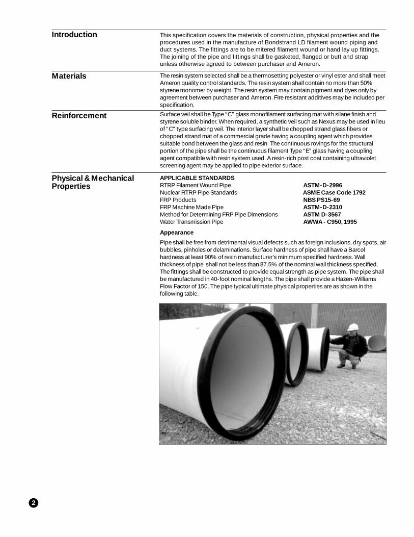
Appearance
Pipe shall be free from detrimental visual defects such as foreign inclusions, dry spots, airbubbles, pinholes or delaminations. Surface hardness of pipe shall have a Barcolhardness at least 90% of resin manufacturer’s minimum specified hardness. Wallthickness of pipe shall not be less than 87.5% of the nominal wall thickness specified.The fittings shall be constructed to provide equal strength as pipe system. The pipe shallbe manufactured in 40-foot nominal lengths. The pipe shall provide a Hazen-WilliamsFlow Factor of 150. The pipe typical ultimate physical properties are as shown in thefollowing table.
Reinforcement
The resin system selected shall be a thermosetting polyester or vinyl ester and shall meetAmeron quality control standards. The resin system shall contain no more than 50%styrene monomer by weight. The resin system may contain pigment and dyes only byagreement between purchaser and Ameron. Fire resistant additives may be included perspecification.
3
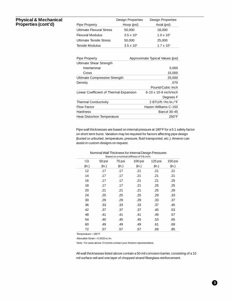
Pipe wall thicknesses are based on internal pressure at 180OF for a 5:1 safety factoron short term burst. Variation may be required for factors affecting pipe design(buried or unburied, temperature, pressure, fluid transported, etc.). Ameron canassist in custom designs on request.
Pipe Property Approximate Typical Values (psi)Ultimate Shear Strength
Interlaminar 5,000Cross 15,000
Ultimate Compressive Strength 25,000Density .070
Pound/Cubic InchLinear Coefficient of Thermal Expansion 6-10 x 10-6 inch/inch
Degrees FThermal Conductivity 2 BTU/ft.2/hr./in./°FFlow Factor Hazen-Williams C-150Hardness Barcol 30-45Heat Distortion Temperature 250°F
Physical & MechanicalProperties (cont’d)
Nominal Wall Thickness for Internal Design PressuresBased on a nominal stiffness of 5 lb.in/in.
I.D. 50 psi 75 psi 100 psi 125 psi 150 psi(in.) (in.) (in.) (in.) (in.) (in.)12 .17 .17 .21 .21 .2114 .17 .17 .21 .21 .2116 .17 .17 .21 .21 .2518 .17 .17 .21 .25 .2520 .21 .21 .21 .25 .2924 .25 .25 .25 .29 .3330 .29 .29 .29 .33 .3736 .33 .33 .33 .37 .4542 .37 .37 .37 .45 .5348 .41 .41 .41 .49 .5754 .45 .45 .45 .53 .6560 .49 .49 .49 .61 .6972 .57 .57 .57 .69 .85
Temperature = 180°F
Allowable Strain = 0.0020 in./in.
Note: For sizes above 72 inches contact your Ameron representative.
Design Properties Design PropertiesPipe Property Hoop (psi) Axial (psi)
Ultimate Flexural Stress 50,000 18,000
Flexural Modulus 3.5 x 10⁶ 1.0 x 10⁶
Ultimate Tensile Stress 50,000 25,000
Tensile Modulus 3.5 x 10⁶ 1.7 x 10⁶
All wall thicknesses listed above contain a 50 mil corrosion barrier, consisting of a 10mil surface veil and one layer of chopped strand fiberglass reinforcement.
4
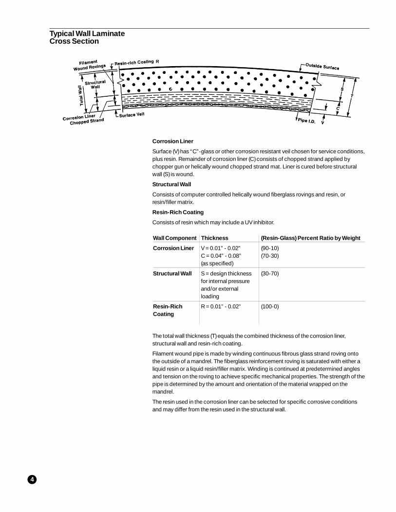
Corrosion Liner
Surface (V) has “C”-glass or other corrosion resistant veil chosen for service conditions,plus resin. Remainder of corrosion liner (C) consists of chopped strand applied bychopper gun or helically wound chopped strand mat. Liner is cured before structuralwall (S) is wound.
Structural Wall
Consists of computer controlled helically wound fiberglass rovings and resin, orresin/filler matrix.
Resin-Rich Coating
Consists of resin which may include a UV inhibitor.
The total wall thickness (T) equals the combined thickness of the corrosion liner,structural wall and resin-rich coating.
Filament wound pipe is made by winding continuous fibrous glass strand roving ontothe outside of a mandrel. The fiberglass reinforcement roving is saturated with either aliquid resin or a liquid resin/filler matrix. Winding is continued at predetermined anglesand tension on the roving to achieve specific mechanical properties. The strength of thepipe is determined by the amount and orientation of the material wrapped on themandrel.
The resin used in the corrosion liner can be selected for specific corrosive conditionsand may differ from the resin used in the structural wall.
Typical Wall LaminateCross Section
Wall Component Thickness (Resin-Glass) Percent Ratio by Weight
Corrosion Liner (90-10)(70-30)
Structural Wall (30-70)
Resin-Rich (100-0)Coating
V = 0.01” - 0.02”C = 0.04” - 0.08”(as specified)
S = design thicknessfor internal pressureand/or externalloading
R = 0.01” - 0.02”
R
5
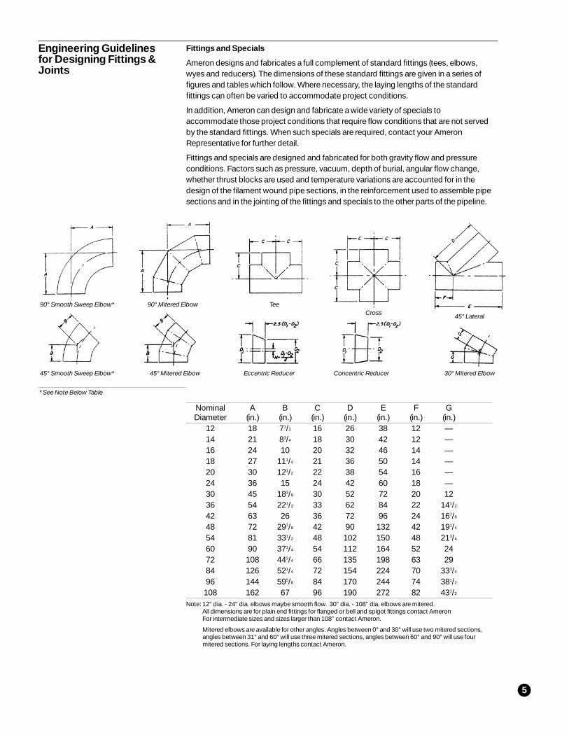
Fittings and Specials
Ameron designs and fabricates a full complement of standard fittings (tees, elbows,wyes and reducers). The dimensions of these standard fittings are given in a series offigures and tables which follow. Where necessary, the laying lengths of the standardfittings can often be varied to accommodate project conditions.
In addition, Ameron can design and fabricate a wide variety of specials toaccommodate those project conditions that require flow conditions that are not servedby the standard fittings. When such specials are required, contact your AmeronRepresentative for further detail.
Fittings and specials are designed and fabricated for both gravity flow and pressureconditions. Factors such as pressure, vacuum, depth of burial, angular flow change,whether thrust blocks are used and temperature variations are accounted for in thedesign of the filament wound pipe sections, in the reinforcement used to assemble pipesections and in the jointing of the fittings and specials to the other parts of the pipeline.
Nominal A B C D E F GDiameter (in.) (in.) (in.) (in.) (in.) (in.) (in.)
12 18 71/2 16 26 38 12 —14 21 83/4 18 30 42 12 —16 24 10 20 32 46 14 —18 27 111/4 21 36 50 14 —20 30 121/2 22 38 54 16 —24 36 15 24 42 60 18 —30 45 183/8 30 52 72 20 1236 54 221/2 33 62 84 22 141/2
42 63 26 36 72 96 24 167/8
48 72 297/8 42 90 132 42 191/4
54 81 331/2 48 102 150 48 213/4
60 90 371/4 54 112 164 52 2472 108 443/4 66 135 198 63 2984 126 521/4 72 154 224 70 333/4
96 144 595/8 84 170 244 74 381/2
108 162 67 96 190 272 82 431/2
Note: 12” dia. - 24” dia. elbows maybe smooth flow. 30” dia. - 108” dia. elbows are mitered.All dimensions are for plain end fittings for flanged or bell and spigot fittings contact AmeronFor intermediate sizes and sizes larger than 108” contact Ameron.
Mitered elbows are available for other angles. Angles between 0° and 30° will use two mitered sections,angles between 31° and 60° will use three mitered sections, angles between 60° and 90° will use fourmitered sections. For laying lengths contact Ameron.
Engineering Guidelinesfor Designing Fittings &Joints
90° Smooth Sweep Elbow* 90° Mitered Elbow Tee
45° Smooth Sweep Elbow* 45° Mitered Elbow Eccentric Reducer Concentric Reducer 30° Mitered Elbow
Cross 45° Lateral
* See Note Below Table
6
Joining Systems
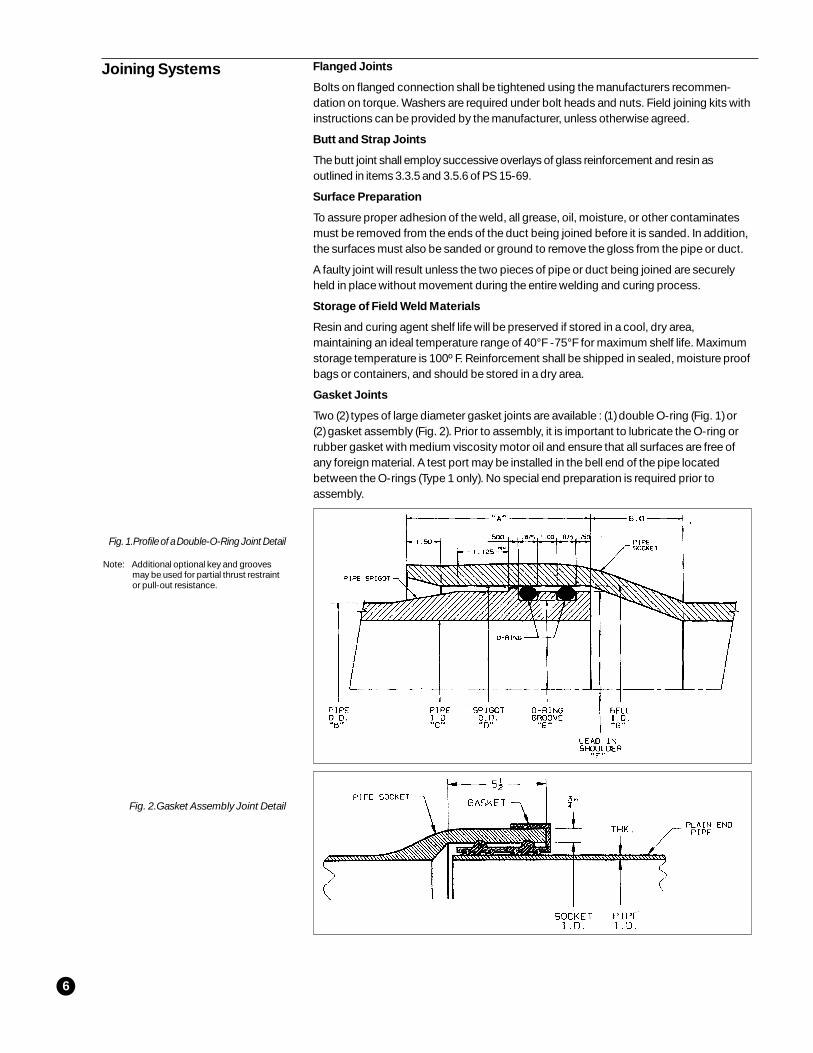
Fig. 1.Profile of a Double-O-Ring Joint Detail
Note: Additional optional key and groovesmay be used for partial thrust restraintor pull-out resistance.
Fig. 2.Gasket Assembly Joint Detail
Flanged Joints
Bolts on flanged connection shall be tightened using the manufacturers recommen-dation on torque. Washers are required under bolt heads and nuts. Field joining kits withinstructions can be provided by the manufacturer, unless otherwise agreed.
Butt and Strap Joints
The butt joint shall employ successive overlays of glass reinforcement and resin asoutlined in items 3.3.5 and 3.5.6 of PS 15-69.
Surface Preparation
To assure proper adhesion of the weld, all grease, oil, moisture, or other contaminatesmust be removed from the ends of the duct being joined before it is sanded. In addition,the surfaces must also be sanded or ground to remove the gloss from the pipe or duct.
A faulty joint will result unless the two pieces of pipe or duct being joined are securelyheld in place without movement during the entire welding and curing process.
Storage of Field Weld Materials
Resin and curing agent shelf life will be preserved if stored in a cool, dry area,maintaining an ideal temperature range of 40°F -75°F for maximum shelf life. Maximumstorage temperature is 100º F. Reinforcement shall be shipped in sealed, moisture proofbags or containers, and should be stored in a dry area.
Gasket Joints
Two (2) types of large diameter gasket joints are available : (1) double O-ring (Fig. 1) or(2) gasket assembly (Fig. 2). Prior to assembly, it is important to lubricate the O-ring orrubber gasket with medium viscosity motor oil and ensure that all surfaces are free ofany foreign material. A test port may be installed in the bell end of the pipe locatedbetween the O-rings (Type 1 only). No special end preparation is required prior toassembly.
7
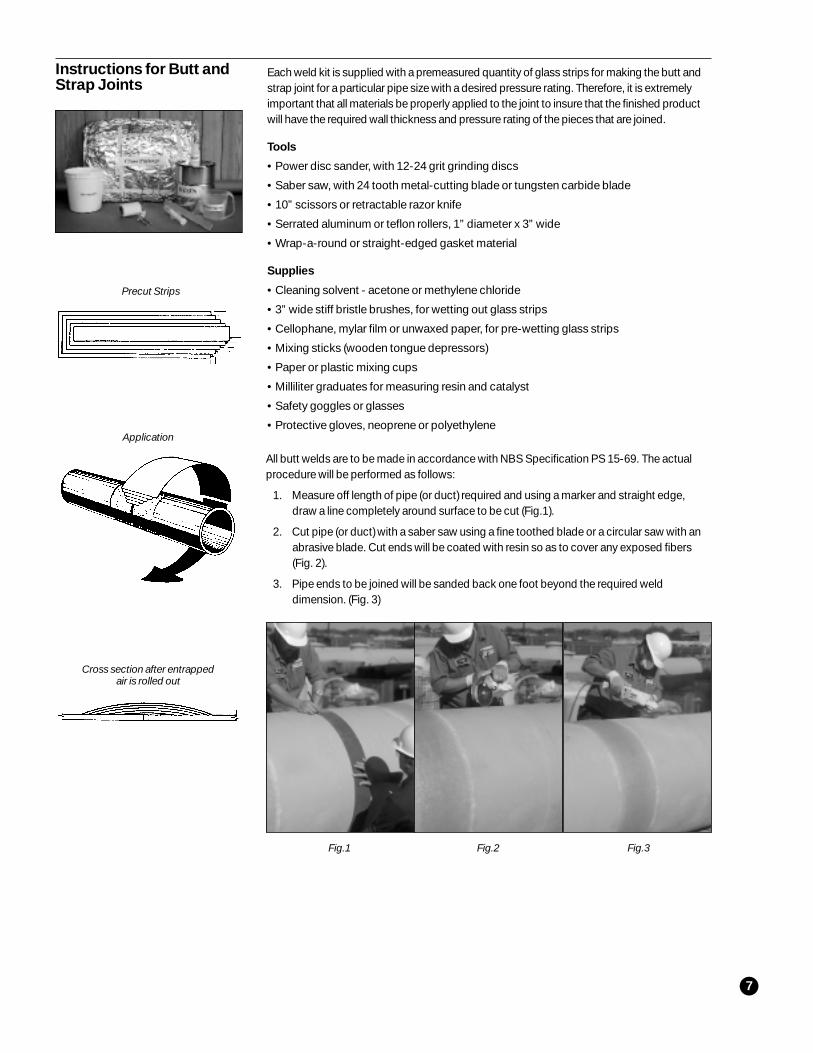
All butt welds are to be made in accordance with NBS Specification PS 15-69. The actualprocedure will be performed as follows:
1. Measure off length of pipe (or duct) required and using a marker and straight edge,draw a line completely around surface to be cut (Fig.1).
2. Cut pipe (or duct) with a saber saw using a fine toothed blade or a circular saw with anabrasive blade. Cut ends will be coated with resin so as to cover any exposed fibers(Fig. 2).
3. Pipe ends to be joined will be sanded back one foot beyond the required welddimension. (Fig. 3)
Each weld kit is supplied with a premeasured quantity of glass strips for making the butt andstrap joint for a particular pipe size with a desired pressure rating. Therefore, it is extremelyimportant that all materials be properly applied to the joint to insure that the finished productwill have the required wall thickness and pressure rating of the pieces that are joined.
Tools
• Power disc sander, with 12-24 grit grinding discs
• Saber saw, with 24 tooth metal-cutting blade or tungsten carbide blade
• 10” scissors or retractable razor knife
• Serrated aluminum or teflon rollers, 1” diameter x 3” wide
• Wrap-a-round or straight-edged gasket material
Supplies
• Cleaning solvent - acetone or methylene chloride
• 3” wide stiff bristle brushes, for wetting out glass strips
• Cellophane, mylar film or unwaxed paper, for pre-wetting glass strips
• Mixing sticks (wooden tongue depressors)
• Paper or plastic mixing cups
• Milliliter graduates for measuring resin and catalyst
• Safety goggles or glasses
• Protective gloves, neoprene or polyethylene
Instructions for Butt andStrap Joints
Precut Strips
Application
Cross section after entrappedair is rolled out
Fig.1 Fig.2 Fig.3
8
7. A serrated roller is then used to smooth the weld and remove any air bubbles that mayhave been trapped beneath the weld when applied (Fig.7).
8. The joint should be made in steps not to exceed 1/4 inch thickness. The outer surfaceof each strip should be lightly sanded prior to the next being applied.
9. An inside weld, consisting of 2 layers of chopped strand mat may be used in largerdiameter pipe.
10. A final gel coat is applied after the weld has taken its initial cure (Fig. 8).
Instructions for Butt andStrap Joints (cont’d)
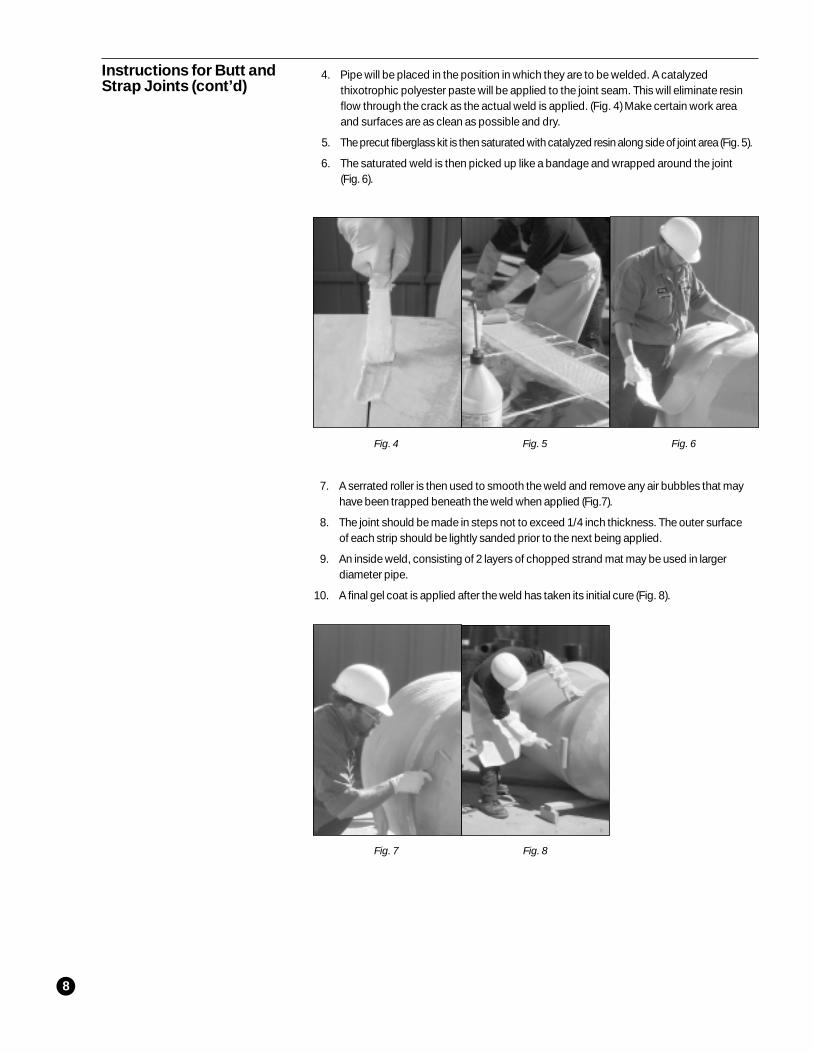
4. Pipe will be placed in the position in which they are to be welded. A catalyzedthixotrophic polyester paste will be applied to the joint seam. This will eliminate resinflow through the crack as the actual weld is applied. (Fig. 4) Make certain work areaand surfaces are as clean as possible and dry.
5. The precut fiberglass kit is then saturated with catalyzed resin along side of joint area (Fig. 5).
6. The saturated weld is then picked up like a bandage and wrapped around the joint(Fig. 6).
Fig. 4 Fig. 5 Fig. 6
Fig. 7 Fig. 8
9
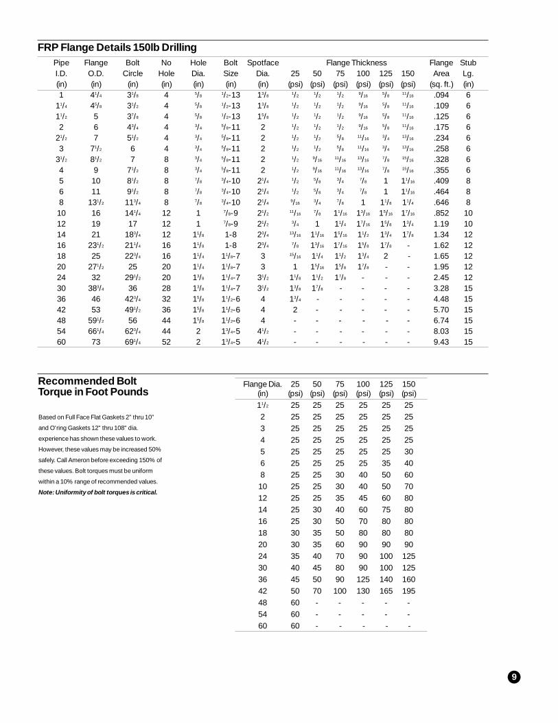
Flange Dia. 25 50 75 100 125 150(in) (psi) (psi) (psi) (psi) (psi) (psi)11/2 25 25 25 25 25 252 25 25 25 25 25 253 25 25 25 25 25 254 25 25 25 25 25 255 25 25 25 25 25 306 25 25 25 25 35 408 25 25 30 40 50 6010 25 25 30 40 50 7012 25 25 35 45 60 8014 25 30 40 60 75 8016 25 30 50 70 80 8018 30 35 50 80 80 8020 30 35 60 90 90 9024 35 40 70 90 100 12530 40 45 80 90 100 12536 45 50 90 125 140 16042 50 70 100 130 165 19548 60 - - - - -54 60 - - - - -60 60 - - - - -
Recommended BoltTorque in Foot Pounds
Pipe Flange Bolt No Hole Bolt Spotface Flange Thickness Flange StubI.D. O.D. Circle Hole Dia. Size Dia. 25 50 75 100 125 150 Area Lg.(in) (in) (in) (in) (in) (in) (in) (psi) (psi) (psi) (psi) (psi) (psi) (sq. ft.) (in)1 41/4 31/8 4 5/8
1/2-13 13/81/2
1/21/2
9/165/8
11/16 .094 611/4 45/8 31/2 4 5/8
1/2-13 13/81/2
1/21/2
9/165/8
11/16 .109 611/2 5 37/8 4 5/8
1/2-13 15/81/2
1/21/2
9/165/8
11/16 .125 62 6 43/4 4 3/4
5/8-11 2 1/21/2
1/29/16
5/811/16 .175 6
21/2 7 51/2 4 3/45/8-11 2 1/2
1/25/8
11/163/4
13/16 .234 63 71/2 6 4 3/4
5/8-11 2 1/21/2
5/811/16
3/413/16 .258 6
31/2 81/2 7 8 3/45/8-11 2 1/2
9/1611/16
13/167/8
15/16 .328 64 9 71/2 8 3/4
5/8-11 2 1/29/16
11/1613/16
7/815/16 .355 6
5 10 81/2 8 7/83/4-10 21/4
1/25/8
3/47/8 1 11/16 .409 8
6 11 91/2 8 7/83/4-10 21/4
1/25/8
3/47/8 1 11/16 .464 8
8 131/2 113/4 8 7/83/4-10 21/4
9/163/4
7/8 1 11/8 11/4 .646 810 16 141/4 12 1 7/8-9 21/2
11/167/8 11/16 13/16 15/16 17/16 .852 10
12 19 17 12 1 7/8-9 21/23/4 1 11/4 17/16 15/8 13/4 1.19 10
14 21 183/4 12 11/8 1-8 23/413/16 11/16 15/16 11/2 13/4 17/8 1.34 12
16 231/2 211/4 16 11/8 1-8 23/47/8 13/16 17/16 15/8 17/8 - 1.62 12
18 25 223/4 16 11/4 11/8-7 3 15/16 11/4 11/2 13/4 2 - 1.65 1220 271/2 25 20 11/4 11/8-7 3 1 15/16 15/8 17/8 - - 1.95 1224 32 291/2 20 13/8 11/4-7 31/2 11/8 11/2 17/8 - - - 2.45 1230 383/4 36 28 13/8 11/4-7 31/2 13/8 17/8 - - - - 3.28 1536 46 423/4 32 15/8 11/2-6 4 13/4 - - - - - 4.48 1542 53 491/2 36 15/8 11/2-6 4 2 - - - - - 5.70 1548 591/2 56 44 15/8 11/2-6 4 - - - - - - 6.74 1554 661/4 623/4 44 2 13/4-5 41/2 - - - - - - 8.03 1560 73 691/4 52 2 13/4-5 41/2 - - - - - - 9.43 15
FRP Flange Details 150lb Drilling
Based on Full Face Flat Gaskets 2” thru 10”
and O’ring Gaskets 12” thru 108” dia.
experience has shown these values to work.
However, these values may be increased 50%
safely. Call Ameron before exceeding 150% of
these values. Bolt torques must be uniform
within a 10% range of recommended values.
Note: Uniformity of bolt torques is critical.
10
Storage
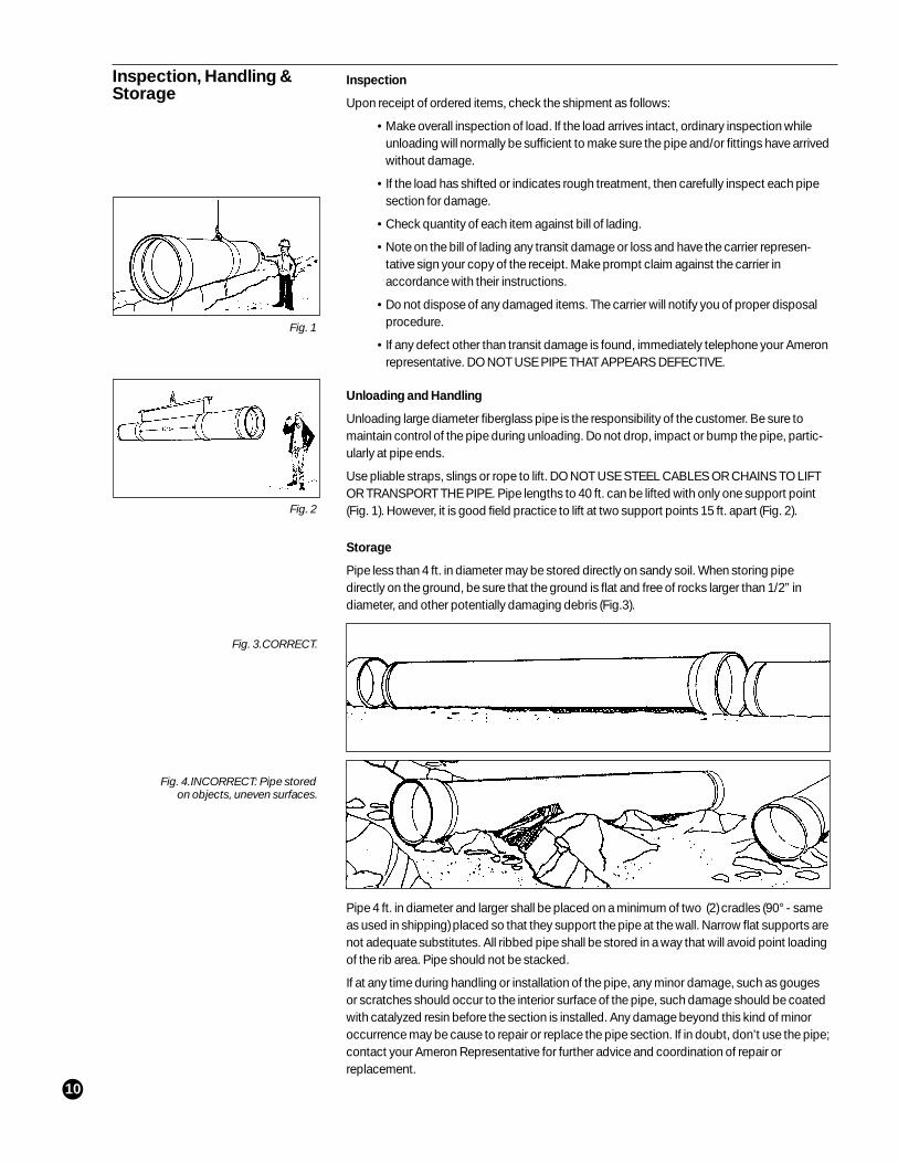
Pipe less than 4 ft. in diameter may be stored directly on sandy soil. When storing pipedirectly on the ground, be sure that the ground is flat and free of rocks larger than 1/2” indiameter, and other potentially damaging debris (Fig.3).
Pipe 4 ft. in diameter and larger shall be placed on a minimum of two (2) cradles (90° - sameas used in shipping) placed so that they support the pipe at the wall. Narrow flat supports arenot adequate substitutes. All ribbed pipe shall be stored in a way that will avoid point loadingof the rib area. Pipe should not be stacked.
If at any time during handling or installation of the pipe, any minor damage, such as gougesor scratches should occur to the interior surface of the pipe, such damage should be coatedwith catalyzed resin before the section is installed. Any damage beyond this kind of minoroccurrence may be cause to repair or replace the pipe section. If in doubt, don’t use the pipe;contact your Ameron Representative for further advice and coordination of repair orreplacement.
Inspection
Upon receipt of ordered items, check the shipment as follows:
• Make overall inspection of load. If the load arrives intact, ordinary inspection whileunloading will normally be sufficient to make sure the pipe and/or fittings have arrivedwithout damage.
• If the load has shifted or indicates rough treatment, then carefully inspect each pipesection for damage.
• Check quantity of each item against bill of lading.
• Note on the bill of lading any transit damage or loss and have the carrier represen-tative sign your copy of the receipt. Make prompt claim against the carrier inaccordance with their instructions.
• Do not dispose of any damaged items. The carrier will notify you of proper disposalprocedure.
• If any defect other than transit damage is found, immediately telephone your Ameronrepresentative. DO NOT USE PIPE THAT APPEARS DEFECTIVE.
Inspection, Handling &Storage
Unloading and Handling
Unloading large diameter fiberglass pipe is the responsibility of the customer. Be sure tomaintain control of the pipe during unloading. Do not drop, impact or bump the pipe, partic-ularly at pipe ends.
Use pliable straps, slings or rope to lift. DO NOT USE STEEL CABLES OR CHAINS TO LIFTOR TRANSPORT THE PIPE. Pipe lengths to 40 ft. can be lifted with only one support point(Fig. 1). However, it is good field practice to lift at two support points 15 ft. apart (Fig. 2).
Fig. 1
Fig. 2
Fig. 4.INCORRECT: Pipe storedon objects, uneven surfaces.
Fig. 3.CORRECT.
11
This recommended practice describes procedures for installing fiberglass reinforcedthermosetting resin pipe produced by Ameron. Piping can support large earth loads andtraffic without excessive deflection through a combination of the pipe’s stiffness and themobilization of lateral passive soil forces. Proper installation techniques in accordancewith the type of burial classification recommended by Ameron’s Engineering Departmentinsures that the necessary passive soil pressure at the sides of the pipe will be developedand maintained.
To achieve proper installation, trenches should be dug to at least 12 inches below the pipebase bedding, and the backfilling and bedding shall be maintained in accordance with thisspecification. Description and identification procedures for suitable backfill materials arefound under Soil Types (pg. 13) and type of burial classifications are described underClasses of Trench Conditions (pg. 14).
Attention is called to the following list of specifications and methods:
ASTM D-698 Moisture-Density Relations of SoilsASTM D-883 Nomenclature Relations of SoilsASTM D-2310 Reinforced Thermosetting Resin Plastic PipeASTMD-2412 External Loading Properties of Plastic Pipe by Parallel Plate LoadingASTM D-2487-66T Tentative Method for Classification of soils for Engineering PurposesASTM D-2487-66T Description of Soils (Visual Manual Procedure)
Instructions forUnderground Installation
Trenching
Trench Width - The width of the trench at any point should be sufficient to provideadequate room for joining the pipe in the ditch with bell holes permissible at the joints. Thepipe O.D. plus 24 inches per side is the normal trench width for large pipe diameters.
Trench Contour - The trench bottom should be continuous, relatively smooth, shapedand compacted in accordance with the bedding and backfilling classification specified.Where ledge rock, hardpan, large rocks, timbers or other foreign materials areencountered, it is advisable to pad the trench bottom using sand or compacted finegrained soils at least 6 inches thick.
Unstable Trench Conditions - Where an unstable soil condition is encountered such asmay be caused by excavation below ground water, the bottom of the trench must bestabilized before laying the pipe. This can usually be accomplished by lowering the watertable at least 12 inches below grade with well-points, shoring the sides, overexcavatingthe bottom material, and replacing with a mixture of sand and coarse gravel or crushedstone or by a combination of the above methods. In the case where shoring or sheeting isrequired, the width of the trench need only be sufficient to provide adequate workingroom. When shoring or sheeting is to be removed, the backfill should be placed andcompacted as the sheeting is being pulled to avoid the occurrence of voids beneath thesheeting. Should soft plastic soil incapable of supporting pipe and pavement beencountered when the excavation is opened, it should be removed and replaced withsuitable material—preferably granular—to a depth that will provide a firm, stable bedding.If dewatering is required, the use of well points is recommended.
Bedding, Backfilling & Compaction
Bedding Grade - The pipe should be uniformly and continuously supported over its entirelength on firm, stable material. Blocking should not be used to change pipe grade or tointermittently support pipe across excavated sections.
Backfilling - Pipe is installed in a wide range of subsoils. These soils should be not onlystable but also applied in such a manner as to physically shield the pipe from damage.Attention should be given to local pipe laying experience which may indicate solutions toparticular pipe bedding problems. Backfill materials according to the requirements underSoil Types (pg. 13) with a particle size of 1/2 inch or less should be used to surround thepipe; it should be placed in layers. Each soil layer should be sufficiently compacted touniformly develop lateral passive soil forces during the backfill operation.
Compaction - Both the bedding and backfill must be compacted to the specified percentof its maximum density as described in Methods D-698. Care should be taken when
12
compacting sidefill to avoid shifting the pipe. During compaction the moisture content of thebackfill material should be within 2 percent of its optimum in accordance with Methods D-698Test for Moisture-Density Relations Soils using 5.5 lb. rammer and 12 inch drop. In caseswhere soil test data are not available, the required moisture for satisfactory compaction ofclay soils may be determined by checking the least amount necessary to hand roll a sampleinto a 1/8” round thread. Vibratory methods are preferred for compaction. The compactionwithin 6 inches to 18 inches of the pipe is usually done with hand tampers. After the side fillshave been compacted to required density, a 12 inch layer of the same material should beplaced over the top of the pipe and lightly tamped. Excessive tamping of this top layer shouldbe avoided as it may result in distortion of the pipe. In wide, deep trenches, lightweight tractorpowered track-mounted equipment of less than 5 psi pressure is permitted at least 24 inchesaway from the pipe and not across the pipe until 4 ft. of overburden is compacted. Wetpuddling or water flooding for consolidating the backfill is not recommended, since this maylead to trapped air cavity around the perimeter of the pipe. Water addition may be used toobtain the optimum compaction of the backfill material.
Lateral Pipe Deflection During Backfillng - Compacting each soil layer by means of amechanical tamper, or similar tool will produce an inward horizontal eccentricity in the pipe.This lateral displacement during compaction is acceptable provided it does not exceed 7percent of the nominal pipe inside diameter. If over 7 percent horizontal eccentricity isencountered, the compaction density should be decreased to 85 percent of the ModifiedProctor maximum dry density, and also notify Ameron of this condition. Less eccentricity isexpected and allowable in the joint area due to the increased stiffness with an additional wallthickness. Pipe strutting to produce a prescribed increased vertical deflection prior to pipebackfilling is sometimes used.
Pipe Sleeving at Rigid Penetrations
The optimum sleeve length shall be at least one nominal pipe diameter. The clearancebetween the O.D. of the pipe and I.D. of the sleeve shall be at least 3 inches. The use of a lowdensity filler such as flexible foam, treated rags, or equivalent at the end of the sleevebetween it and the pipe will prevent the trench fill from entering the sleeve.
Soil Types
A soil is considered stable if it provides dependable support to the pipe and undergoes onlyslight volume change with variation in its moisture content. The ability of a soil to providesupport depends upon its resistance to consolidation and its shear strength. In general,coarse grained soils are considered stable. In ASTM D-2487- 66T, these are defined as soilsof which 50 percent or less pass U.S. Standard No. 200 sieve. The particle passing throughNo. 200 sieve is about the smallest size visible to the naked eye.
Using the group symbols of ASTM D-2487-66T (under Soil Classification Symbols, pg. 14),the following are considered stable backfill: GW, GP, GM, GC, SW, SP, provided thatmaximum particle size is not greater than 1/2 inch.
In terms of overall use, gravel with fines and sand are the best backfill material for pressurepipe. Sand or gravel mixed with silts or clays, in which the sand or gravel constitutes at least50 percent of the mixture, is also suitable. Certain soils should not be used as backfillmaterial; these include highly organic soils, identified by odor or spongy feel, and fat, highlyplastic expansive clay. Frozen soil should not be placed in contact with the pipe.
Field Identification of Soils
Gravel - Minimum grain size 1/4 inch.
Sand - Individual grains visible to the naked eye with maximum particle size about 0.25 inch.Fine sand displays dilitancy and is nonplastic. Note: To test for dilitancy, place pat of moistsoil on palm of hand. If the soil displays dilitancy, water will appear at the surface of the pat onshaking and disappear when the pat is compressed by the fingers.
Silt - Individual grains difficult to see with the naked eye. May be slightly plastic. Displaysdilitancy. Easily washed from fingers. Low dry strength.
Lean Clay - Individual grains difficult to see with the naked eye. Dry lumps have moderate tohigh strength. Can be rolled into a 1/8 inch thread having low to moderate strength. Does notdisplay dilitancy.
Instructions forUnderground Installation(cont’d)
13
Fat Clay - Shows no or very slow dilitancy and should not be used unless mixed withcoarse grained material. Has high dry strength. Has soapy feel and shiny streak results iffingernail is run over damp surface. Can be rolled into 1/8 inch threads having relativelyhigh strength.
Soil Classification Symbols
GW - Well-graded gravel, gravel-sand mixtures, little or no fines.
GP - Poorly graded gravel, gravel-sand mixtures, little or no fines.
GM - Silty gravel, poorly graded gravel-sand-silt mixtures.
GC - Clay gravel, poorly graded gravel-sand-clay mixtures.
SW - Well-graded sands, gravelly sands, little or no fines.
SP - Poorly graded sands, gravelly sands, little or no fines.
SM - Silty sands, poorly graded sand-silt mixtures.
Classes of Trench Conditions
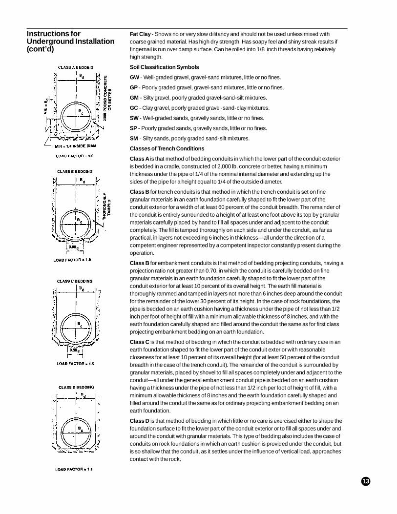
Class A is that method of bedding conduits in which the lower part of the conduit exterioris bedded in a cradle, constructed of 2,000 lb. concrete or better, having a minimumthickness under the pipe of 1/4 of the nominal internal diameter and extending up thesides of the pipe for a height equal to 1/4 of the outside diameter.
Class B for trench conduits is that method in which the trench conduit is set on finegranular materials in an earth foundation carefully shaped to fit the lower part of theconduit exterior for a width of at least 60 percent of the conduit breadth. The remainder ofthe conduit is entirely surrounded to a height of at least one foot above its top by granularmaterials carefully placed by hand to fill all spaces under and adjacent to the conduitcompletely. The fill is tamped thoroughly on each side and under the conduit, as far aspractical, in layers not exceeding 6 inches in thickness—all under the direction of acompetent engineer represented by a competent inspector constantly present during theoperation.
Class B for embankment conduits is that method of bedding projecting conduits, having aprojection ratio not greater than 0.70, in which the conduit is carefully bedded on finegranular materials in an earth foundation carefully shaped to fit the lower part of theconduit exterior for at least 10 percent of its overall height. The earth fill material isthoroughly rammed and tamped in layers not more than 6 inches deep around the conduitfor the remainder of the lower 30 percent of its height. In the case of rock foundations, thepipe is bedded on an earth cushion having a thickness under the pipe of not less than 1/2inch per foot of height of fill with a minimum allowable thickness of 8 inches, and with theearth foundation carefully shaped and filled around the conduit the same as for first classprojecting embankment bedding on an earth foundation.
Class C is that method of bedding in which the conduit is bedded with ordinary care in anearth foundation shaped to fit the lower part of the conduit exterior with reasonablecloseness for at least 10 percent of its overall height (for at least 50 percent of the conduitbreadth in the case of the trench conduit). The remainder of the conduit is surrounded bygranular materials, placed by shovel to fill all spaces completely under and adjacent to theconduit—all under the general embankment conduit pipe is bedded on an earth cushionhaving a thickness under the pipe of not less than 1/2 inch per foot of height of fill, with aminimum allowable thickness of 8 inches and the earth foundation carefully shaped andfilled around the conduit the same as for ordinary projecting embankment bedding on anearth foundation.
Class D is that method of bedding in which little or no care is exercised either to shape thefoundation surface to fit the lower part of the conduit exterior or to fill all spaces under andaround the conduit with granular materials. This type of bedding also includes the case ofconduits on rock foundations in which an earth cushion is provided under the conduit, butis so shallow that the conduit, as it settles under the influence of vertical load, approachescontact with the rock.
Instructions forUnderground Installation(cont’d)
14
The generic term “Glass-fiber-reinforced plastic” can refer to many plastic materials.The plastic duct construction covered in this section is confined to glass-fiberreinforced thermosetting polyester fabricated to the Department of CommerceVoluntary Standard NBS PS 15-69
The choice of composite materials is the responsibility of the design engineer whosechoice should include considerations of both the corrosives encountered and the fireretardancy required.
Ameron duct can be manufactured to have a flame spread rating of 25 or less asmeasured in accordance with ASTM E-84-69 “Standard Method of Test for SurfaceBurning Characteristics of Building Materials”.
Materials
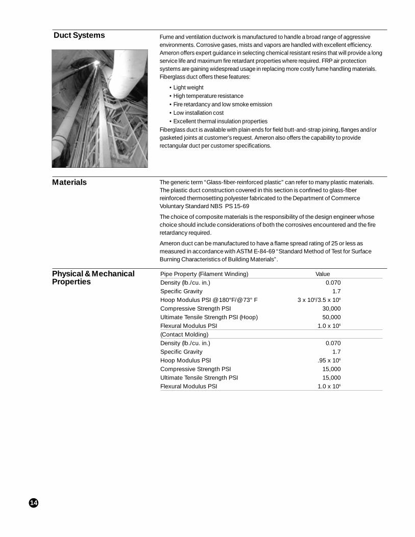
Fume and ventilation ductwork is manufactured to handle a broad range of aggressiveenvironments. Corrosive gases, mists and vapors are handled with excellent efficiency.Ameron offers expert guidance in selecting chemical resistant resins that will provide a longservice life and maximum fire retardant properties where required. FRP air protectionsystems are gaining widespread usage in replacing more costly fume handling materials.Fiberglass duct offers these features:
• Light weight• High temperature resistance• Fire retardancy and low smoke emission• Low installation cost• Excellent thermal insulation properties
Fiberglass duct is available with plain ends for field butt-and-strap joining, flanges and/orgasketed joints at customer’s request. Ameron also offers the capability to providerectangular duct per customer specifications.
Duct Systems
Pipe Property (Filament Winding) ValueDensity (lb./cu. in.) 0.070Specific Gravity 1.7Hoop Modulus PSI @ 180°F/@ 73° F 3 x 10⁶/3.5 x 106
Compressive Strength PSI 30,000Ultimate Tensile Strength PSI (Hoop) 50,000Flexural Modulus PSI 1.0 x 10⁶
(Contact Molding)Density (lb./cu. in.) 0.070Specific Gravity 1.7Hoop Modulus PSI .95 x 106
Compressive Strength PSI 15,000Ultimate Tensile Strength PSI 15,000Flexural Modulus PSI 1.0 x 10⁶
Physical & MechanicalProperties
15
System Design
I.D. Wall Allowable Allowable Flange Flange Bolt Bolt No. ofThickness Vacuum2 Pressure2 Dia. Thickness Circle Hole Bolt
(Min.) (O.D.) Dia. Dia. Holes
(in) (in) (in. of water) (in. of water) (in) (in) (in) (in) (in)
2 0.125 405 750 63/81/4 5 7/16 4
3 0.125 405 500 73/81/4 6 7/16 4
4 0.125 210 410 83/81/4 7 7/16 4
6 0.125 64 350 103/81/4 9 7/16 8
8 0.125 30 180 123/81/4 11 7/16 8
10 0.125 16 340 143/83/8 13 7/16 12
12 0.125 9 280 163/83/8 15 7/16 12
14 0.125 7 220 183/83/8 17 7/16 12
16 0.125 6 290 203/81/2 19 7/16 16
18 0.125 5 240 223/81/2 21 7/16 16
20 0.125 5 190 243/81/2 23 7/16 20
24 0.187 9 140 283/81/2 27 7/16 20
30 0.187 7 100 343/81/2 33 7/16 28
36 0.187 5 70 403/81/2 39 7/16 32
42 0.250 10 120 463/85/8 45 7/16 36
48 0.250 9 100 543/85/8 52 9/16 44
54 0.250 7 80 603/85/8 58 9/16 44
60 0.250 6 60 663/85/8 64 9/16 52
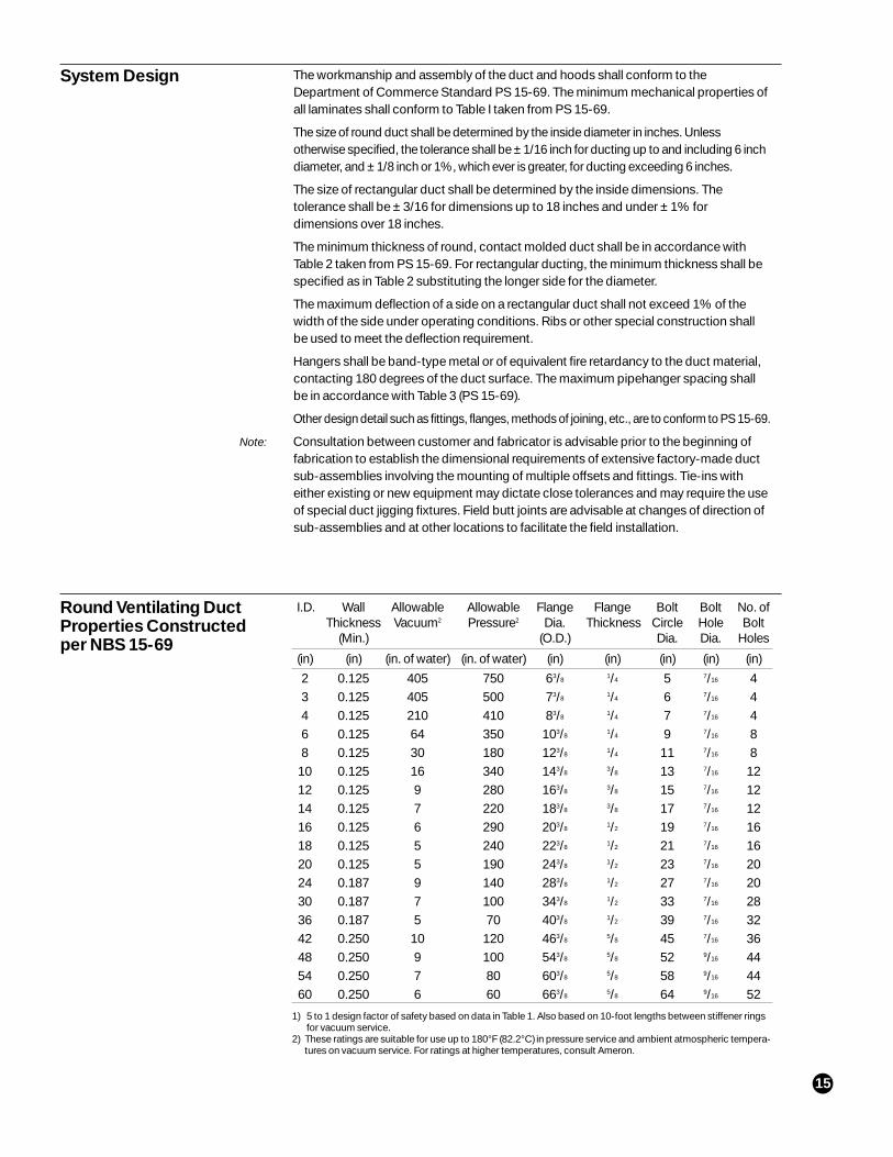
1) 5 to 1 design factor of safety based on data in Table 1. Also based on 10-foot lengths between stiffener ringsfor vacuum service.
2) These ratings are suitable for use up to 180°F (82.2°C) in pressure service and ambient atmospheric tempera-tures on vacuum service. For ratings at higher temperatures, consult Ameron.
Round Ventilating DuctProperties Constructedper NBS 15-69
The workmanship and assembly of the duct and hoods shall conform to theDepartment of Commerce Standard PS 15-69. The minimum mechanical properties ofall laminates shall conform to Table I taken from PS 15-69.
The size of round duct shall be determined by the inside diameter in inches. Unlessotherwise specified, the tolerance shall be ± 1/16 inch for ducting up to and including 6 inchdiameter, and ± 1/8 inch or 1%, which ever is greater, for ducting exceeding 6 inches.
The size of rectangular duct shall be determined by the inside dimensions. Thetolerance shall be ± 3/16 for dimensions up to 18 inches and under ± 1% fordimensions over 18 inches.
The minimum thickness of round, contact molded duct shall be in accordance withTable 2 taken from PS 15-69. For rectangular ducting, the minimum thickness shall bespecified as in Table 2 substituting the longer side for the diameter.
The maximum deflection of a side on a rectangular duct shall not exceed 1% of thewidth of the side under operating conditions. Ribs or other special construction shallbe used to meet the deflection requirement.
Hangers shall be band-type metal or of equivalent fire retardancy to the duct material,contacting 180 degrees of the duct surface. The maximum pipehanger spacing shallbe in accordance with Table 3 (PS 15-69).
Other design detail such as fittings, flanges, methods of joining, etc., are to conform to PS 15-69.
Consultation between customer and fabricator is advisable prior to the beginning offabrication to establish the dimensional requirements of extensive factory-made ductsub-assemblies involving the mounting of multiple offsets and fittings. Tie-ins witheither existing or new equipment may dictate close tolerances and may require the useof special duct jigging fixtures. Field butt joints are advisable at changes of direction ofsub-assemblies and at other locations to facilitate the field installation.
Note:
16
Installation
Recommended Practicesfor Shipping & Installationof Reinforced Plastic Ductas Described in ProductStandard PS15-69
Shipping
The purpose of these recommended standard practices is to serve as a supplement toProduct Standard PS 15-69. These recommendations include dimensional tolerancesof duct sub-assemblies which are fabricated by the manufacturer prior to shipment.They also serve as a guide for shipping, installation, and use of reinforced plasticchemical resistant ducting.
Chemical resistant fiberglass reinforced plastic duct is used to handle corrosive gasesand vapors which are encountered in industrial processes. Contained herein areminimum standards of materials, construction and workmanship deemed necessary toinsure minimum fire hazard in the operation of these systems.
Because of the light weight of FRP the chief determinants of the overall dimensions of thesub-assemblies will be the dimensional shipping limitations and the access passagedimensions at the installation site. The overall dimensions of the sub-assemblies shall bedetermined by the requirements of both the manufacturer and the customer.
The manufacturer shall protect all flange faces, small diameter duct, and the more fragileappurtenances of the sub-assemblies, with padding between pieces of duct in order toprevent one piece from impacting with another, and by crating or other means for shipment.
Upon arrival at the installation site, the duct shall be carefully examined by the customer fordamage in transit. If damage has occurred, a claim shall be filed with the carrier by thecustomer.
Duct and sub-assemblies shall be unloaded with care and stored in a location wherethey will be free from damage. Impact of a tool or other heavy object may result infracture of the inner lining and affect the service life of the duct.
Large sub-assemblies shall be supported during unloading to prevent excessivedeflection and overstressing.
The duct should not pass through fire walls or fire-rated floors. When penetrating a fire-ratedshaft wall or fire partition, the opening shall be protected by fire dampers. Duct shall not beinstalled in concealed spaces other than fire-rated shafts.
Manifolded systems shall be limited to 50,000 cfm capacity, except when engineeringconsiderations necessitate larger manifolded systems. Such systems shall be designed bya registered engineer.
Flexible Connections
Vibration isolation between ductwork and air-moving equipment can be accomplished byflexible connections at the inlet and discharge of the equipment.
All hoods and air-moving equipment (AME) which are part of the system shall have flamespread rating equal to the material of the duct system. Design and workmanship shall meetphysical requirements consistent with PS 15-69.
Fire Protection
Automatic protection shall be provided at the duct intake, hood, canopy and the immediateareas thereof to quickly extinguish source fires. Sensing elements provided at these afore-mentioned sources shall be arranged to shut down the blower system. This automatic shutdown shall be waived if fire control can be improved through continued operation.
Identification
Fiberglass reinforced plastic duct components shall be identified as to the manufac-turer, type of material and flame spread rating.
17
Polyester Vinyl Ester% Concentration % Concentration
Substance @ Max. Temperature °F @ Max. Temperature °FACIDSAcetic Acid 2 170 10 200Acetic Acid 25 170 25 200Acetic Acid 50 125 75 150Benzene Sulfuric 30 75 Sat. 200Benzoic Sat. 170 Sat. 200Chloracetic NR NR 50 150Chromic 5 75 10 80*Fluoboric Sat. 75 20 180Fluosilicic 25 75 25 100Formic NR NR 50 100Hydrobromic 50 150 50 150Hydrochloric 20 150 10 200Hydrochloric 30 150 20 200Hydrochloric 37 100 37 100*Hydrofluoric NR NR 10 100Hypochlorous 10 75 10 150Hypochlorous 20 75 20 120Lactic Sat. 160 Sat. 200Nitric 5 160 5 150Nitric 10 80 10 120Oxalic Sat. 80 Sat. 200Perchloric NR NR 10 150Perchloric NR NR 30 80Phosphoric - - 10 200Phosphoric - - 25 200Phosphoric 85 130 85 200Phthalic Sat. 100 Sat. 200Sulfuric 25 150 25 180Sulfuric NR NR 50 180Sulfurous NR NR Sat. 100Tannic Sat. 170 Sat. 200Tartaric Sat. 170 Sat. 200
ALKALIESAmmonium Hydroxide 3 75 5 130Ammonium Hydroxide NR NR 10 120Ammonium Hydroxide NR NR 20 100Ammonium Bicarbonate 15 130 50 150Ammonium Carbonate NR NR 50 100*Calcium Hydroxide 25 170 10 160Magnesium Carbonate Sat. 160 Sat. 180Potassium Hydroxide NR NR 25 150Sodium Carbonate 20 75 20 160*Sodium Hydroxide NR NR 5 150*Sodium Hydroxide NR NR 10 150*Sodium Hydroxide NR NR 25 120Trisodium Phosphate NR NR Sat. 200
GASES & VAPORSCarbon Dioxide - 200 - 200Carbon Monoxide - 160 - 200Chlorine Dry - 140 - 200Chlorine Wet - NR - 200Hydrogen Chloride Dry - 75 - 200
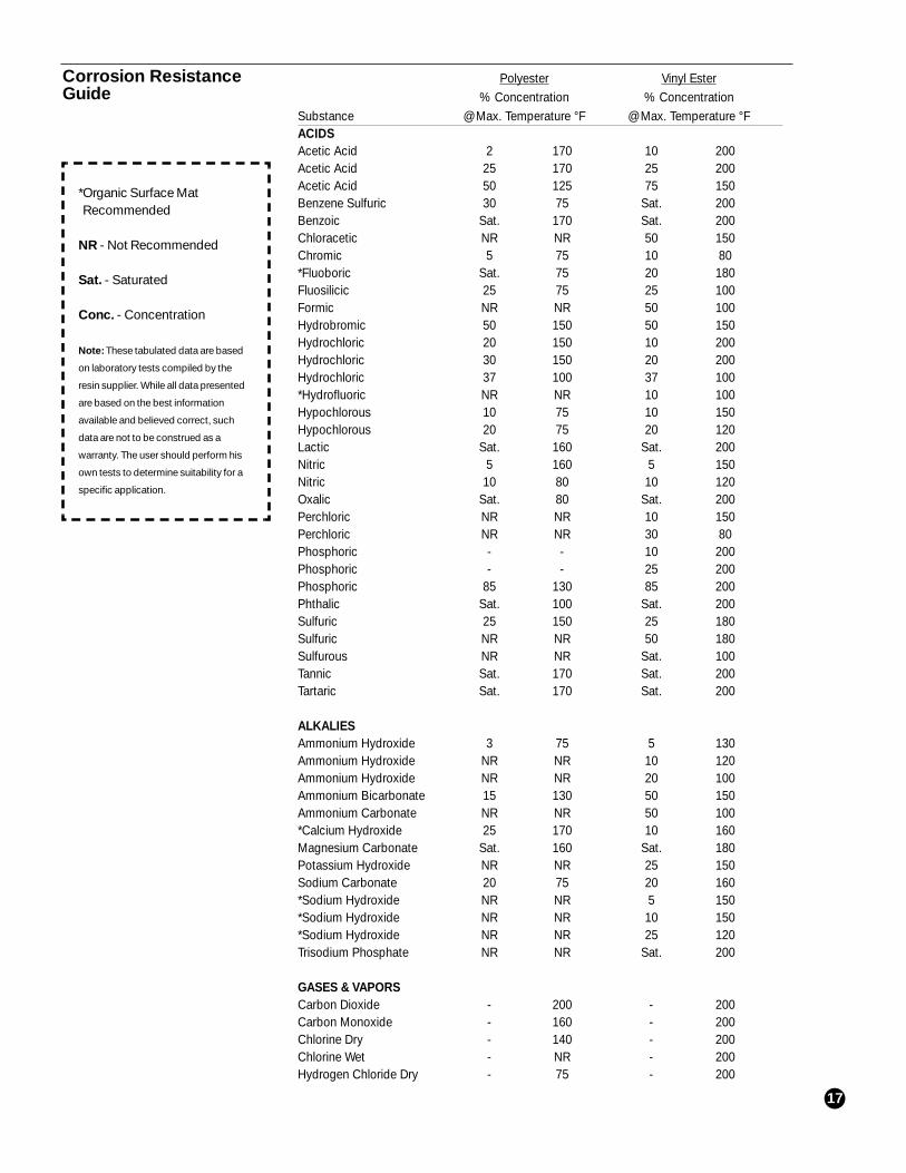
Corrosion ResistanceGuide
*Organic Surface MatRecommended
NR - Not Recommended
Sat. - Saturated
Conc. - Concentration
Note: These tabulated data are based
on laboratory tests compiled by the
resin supplier. While all data presented
are based on the best information
available and believed correct, such
data are not to be construed as a
warranty. The user should perform his
own tests to determine suitability for a
specific application.
18
Polyester Vinyl Ester% Concentration % Concentration
Substance @ Max. Temperature °F @ Max. Temperature °FHydrogen Sulfide - 140 - 170Sulfur Dioxide - 75 - 200Sulfur Trioxide - 75 - 200
SALTSAluminum Sulfate Sat. 170 Sat. 200Aluminum Nitrate 60 150 10 200Ammonium Sulfate Sat. 170 Sat. 200Calcium Chloride Sat. 170 Sat. 200Chromium Sulfate - - Sat. 170*Cupric Chloride Sat. 170 Sat. 200*Cupric Cyanide - - Sat. 200*Cupric Nitrate Sat. 170 Sat. 200*Cupric Sulfate Sat. 140 Sat. 200*Cuprous Sulfate Sat. 170 Sat. 200Ferric Nitrate Sat. 170 Sat. 200Ferrous Chloride Sat. 170 Sat. 200Lead Acetate Sat. 170 Sat. 150Lead Chloride - - Sat. 200Lead Nitrate - - Sat. 200Magnesium Carbonate Sat. 150 Sat. 150Magnesium Chloride Sat. 170 Sat. 200Magnesium Nitrate Sat. 150 Sat. 200Mercuric Chloride Sat. 170 Sat. 200Mercurous Chloride Sat. 170 Sat. 200Nickel Nitrate Sat. 170 Sat. 200Nickel Sulfate Sat. 170 Sat. 200Potassium Chloride Sat. 170 Sat. 200Potassium Dichromate Sat. 170 Sat. 200Potassium Ferrocyanide Sat. 170 Sat. 200Potassium Nitrate Sat. 170 Sat. 200Potassium Permanganate Sat. 170 Sat. 200Sodium Acetate Sat. 170 Sat. 200Sodium Chloride Sat. 170 Sat. 200Sodium Nitrate Sat. 170 Sat. 200Stannic Chloride Sat. 170 Sat. 180Zinc Chloride Sat. 170 Sat. 200
ORGANIC CHEMICALSAcetone/Water NR NR 10 100Carbon Tetrachloride NR NR 100 100Diethyl Ether NR NR 100 75Diethyl Phthalate NR NR 100 80Ethanol 95 80 100 75Ethylene Chloride NR NR 100 75Gasoline 100 75 100 75Kerosene 100 75 100 75Perchlorethylene 100 75 100 80Sour Crude Oil 100 120 100 200Xylene 100 75 100 200
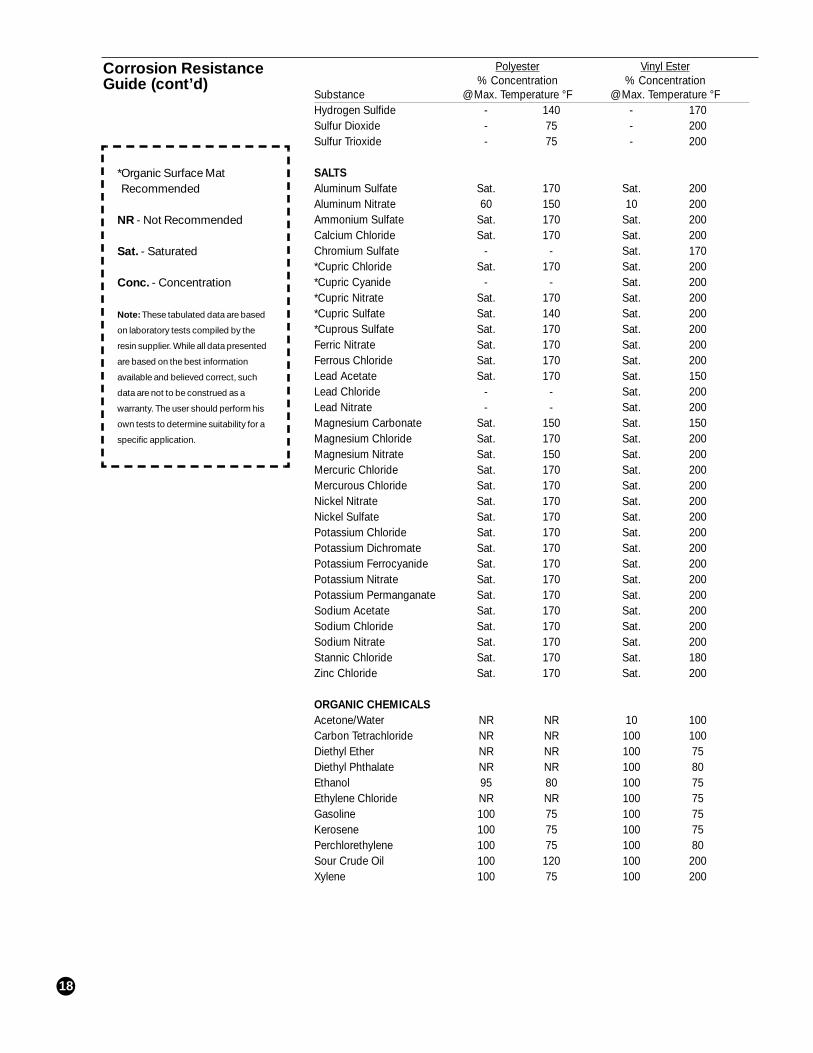
Corrosion ResistanceGuide (cont’d)
*Organic Surface MatRecommended
NR - Not Recommended
Sat. - Saturated
Conc. - Concentration
Note: These tabulated data are based
on laboratory tests compiled by the
resin supplier. While all data presented
are based on the best information
available and believed correct, such
data are not to be construed as a
warranty. The user should perform his
own tests to determine suitability for a
specific application.
19
Important Notice This literature and the information and recommendations it contains are based on data reasonably believed to bereliable. However, such factors as variations in environment, application or installation, changes in operatingprocedures, or extrapolation of data may cause different results. Ameron makes no representation or warranty,express or implied, including warranties of merchantability or fitness for purpose, as to the accuracy, adequacyor completeness of the recommendations or information contained herein. Ameron assumes no liabilitywhatsoever in connection with this literature or the information or recommendations it contains. Product specifi-cations are subject to change.
Engineering Controls:
• A fabrication area should be set up in which to perform as much of thefabrication work as is practical or possible.
• Ventilation of the work area should be controlled. This can be done by meansof fans or dust collectors.
• Work area should be kept clean, including floor or other horizontal surfaces.Rinsing with water or sweeping with brushes or brooms (using floor sweep)is recommended. Never use compressed air to clean area or to remove dustfor personal cleaning. Brushes should be used to remove residue fromtapered surfaces.
Personal Protection:
• Barrier cream should be applied to the skin in areas which may be exposedto shavings prior to beginning work.
• Clean clothes should be worn each day. Do not wear clothing that has notbeen laundered to begin a work shift. More frequent changing may berequired by conditions.
• Long sleeved shirts or worksuits should be used. Tape should be used atsleeve opening.
• Cotton or flannel shirts under workshirts may be worn to prevent rubbing ofskin at opening of worksuit.
• Gloves with elastic cuff should be worn at all times. Replace worn orcontaminated gloves as necessary. Gloves with flared, stiff cuffs act as agathering funnel for shavings.
• Pant legs should be worn outside work boots. If necessary for safetypurposes, the pant legs can be taped to fit closely to the boot. Over-the-calfsocks can be used to prevent chafing of the boot on the skin.
• Wristbands and watches should be removed to prevent rubbing or accumu-lation of particles on skin underneath the band.
• Dust masks and face shields should be used as necessary and practical.Contact points with the skin should be kept free of dust to prevent dust frombeing imbedded into skin from movement of the mask during normal use.
Personal Hygiene:
• Wash exposed skin with soap solution (liquid soap preferred) and cool water.
• Use washcloth with “brushing” motion to remove dust or fibers. Do notscrub the skin. This could result in the fibers being imbedded into the skin.
• Rinse thoroughly with clean, cold water.
• Apply lotion or cream to skin (non-detergent formulas such as baby lotion) tosoothe irritation or prevent further immediate irritation.
Safety Recommendations
Limitations in Service The duct system shall only be used in the environment for which it was designed.
The manufacturer’s recommendation on support spacing usually allows for the weightof a certain amount of corrosive condensate in the duct. If corrosive condensation islikely to build up at a low point in the system beyond that used in the design calculation,drains should be provided to allow for its removal.
If the system is designed to allow for a graded vacuum requirement, as determined bythe flow characteristics, provision shall be made to prevent an interruption of flowwhich would result in the entire system being placed under maximum vacuum.Otherwise, the entire system shall be designed for the maximum vacuum.

20
Notes

21
FIBERGLASS - COMPOSITE PIPE GROUP - HEADQUARTERS
P.O. Box 801148 • Houston, TX 77280 • Tel: (713) 690-7777 • Fax: (713) 690-2842 • http://www.ameron.com
EuropeAmeron B.V.J.F. Kennedylaan 74191 MZ GeldermalsenThe NetherlandsTel: +31 345 587 587Fax: +31 345 587 [email protected]
AmericasP.O. Box 878Burkburnett, TX 76354Tel: (940) 569-1471Fax: (940) 569-2764
Centron InternationalP.O. Box 490600 FM 1195 SouthMineral Wells, Texas 76068Tel: (940) 325-1341Fax: (940) 325-9681http://www.centrongre.com
AsiaAmeron (Pte) Ltd.No. 7A, Tuas Avenue 3Singapore 639407Tel: 65 861 6118Fax: 65 862 1302/861 [email protected]
© 2000 Ameron • FP875 (11/00) • Printed in U.S.A. • 5M [3005]