bondstrand 2400 series
TRANSCRIPT
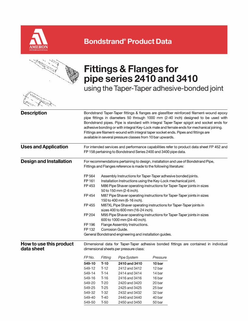
Series 2400 FiberglassPipe and Fittings
using Key-Lock® mechanical joint, Double O-ring or Taper/ Taper adhesive joint
Uses and applications Saltwater and seawater lines
Brackish water lines Fire protection systems
Potable water lines
Waste water and sewage systems Drainage systems Oil field reinjection systems
Crude oil transmission lines
Temporary pipelines Electrical conduit
General industrial service for mildly corrosive liquids
Performance Laminate meets requirements of API Specification 15LR. Pipe wall design using a 124 N/mm
2 hydrostatic design basis (Procedure B.) with a 0.5 service
factor. Liner thickness: 0.5 mm. Maximum operating temperature: 120°C (250°F) ASTM D-2310 Classification: RTRP-11FW (or RTRP-11 FE as applicable). This system is designed to provide minimal 4:1 safety factor in accordance with ASTM D-1599.
Description Pipe
Filament-wound fiberglass reinforced epoxy pipe with Key-Lock
male and female or Double O-Ring male and female mechanical joint or Taper/ Taper male and female adhesive joint.
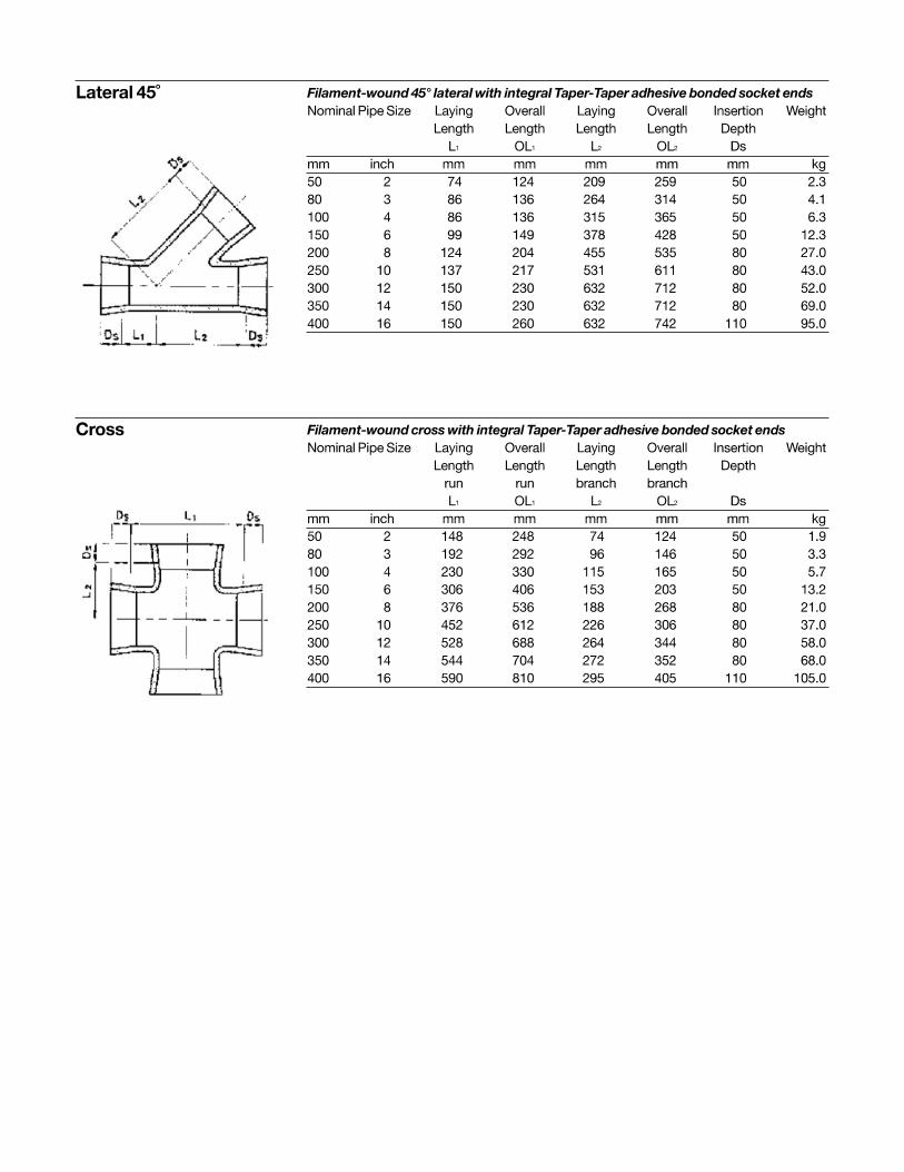
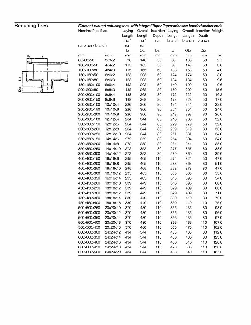
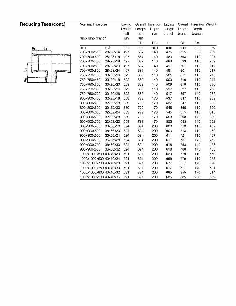
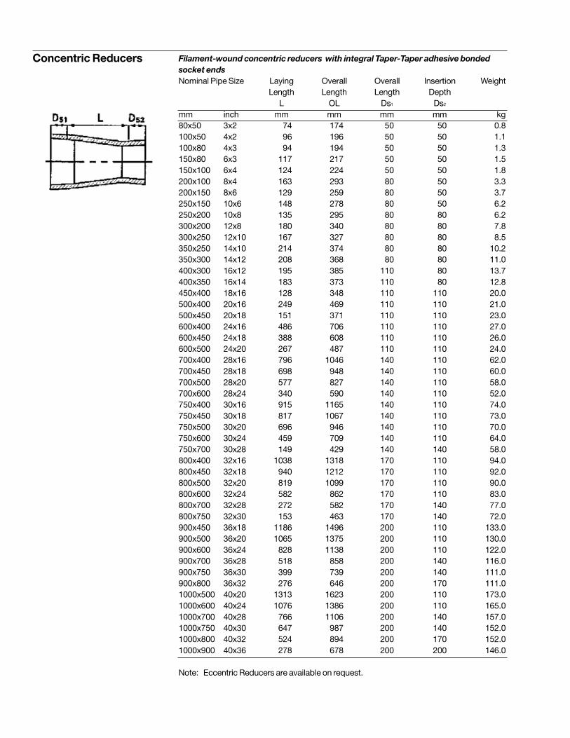
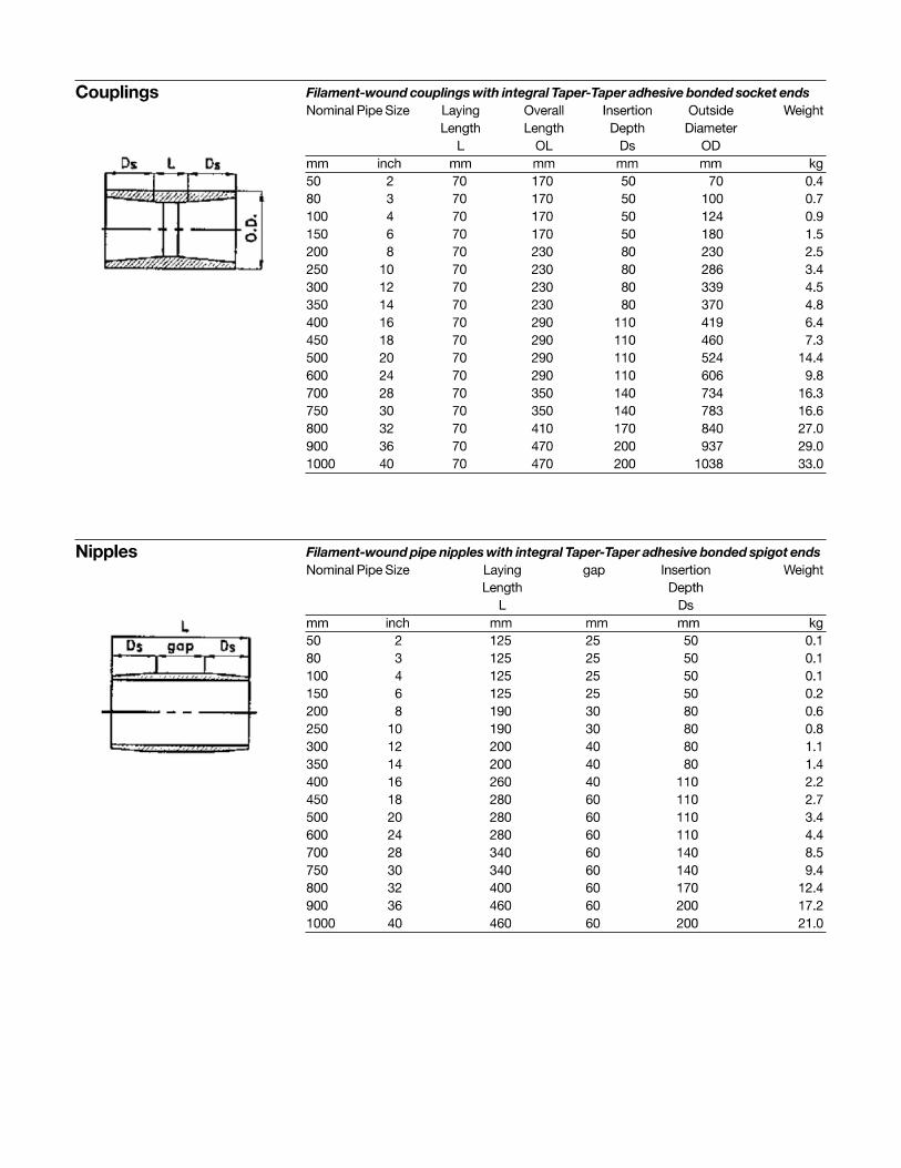
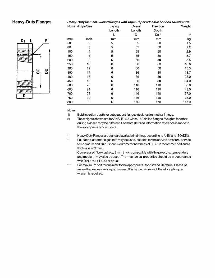
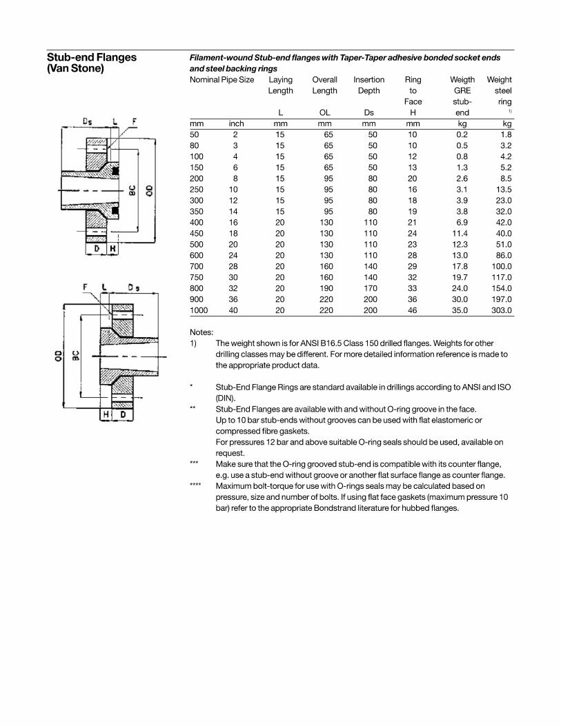
Fittings Standard filament-wound couplings, 45° and 90° Elbows, Tees and Reducing Tees, Concentric Reducers, Flanges* and Nipples. Special fittings are available on request.
* Flanges are available with the following drillings : ANSI B16.5 Class 150 and 300, DIN, ISO & JIS. Other drilling patterns are available on request.
For dimensional data and standard configurations for fittings, please refer to respective Fitting Guides.
Optional, the system can be supplied conductive - Bondstrand 2400C or Fireproofing 2400-FP. For Conductive ASTM D-2310 Classification: RTRP-11AW for pipes or RTRP-11AE as applicable
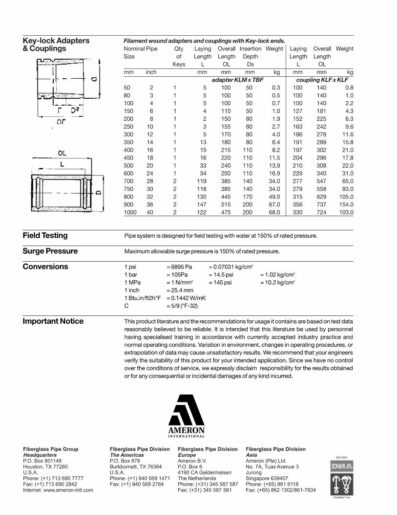
Joining systems Key-Lock
integral filament-wound male and female or Double O-Ring male and female
mechanical joint assembled with locking keys. Hydrostatic seal by means of an elastomeric O-ring. Taper/ Taper integral filament-wound male and female adhesive bonded joint.
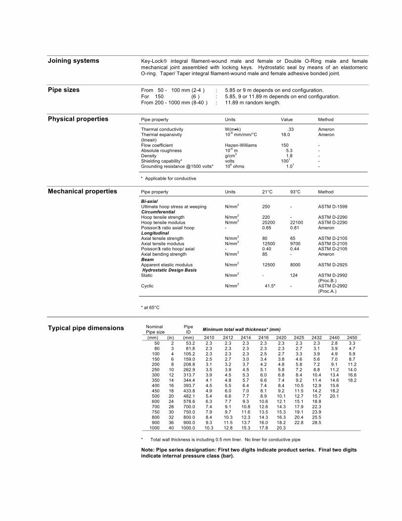
Pipe sizes From 50 - 100 mm (2-4 ) : 5.85 or 9 m depends on end configuration. For 150 (6 ) : 5.85, 9 or 11.89 m depends on end configuration. From 200 - 1000 mm (8-40 ) : 11.89 m random length.
Physical properties Pipe property Units Value Method
Thermal conductivity W(m k) .33 Ameron Thermal expansivity 10
-6 mm/mm/°C 18.0 Ameron
(lineair)Flow coefficient Hazen-Williams 150 - Absolute roughness 10
-6 m 5.3 -
Density g/cm3
1.8 - Shielding capability* volts 100
1 -
Grounding resistance @1500 volts* 106
ohms 1.01
-
* Applicable for conductive
Mechanical properties Pipe property Units 21°C 93°C Method
Bi-axial Ultimate hoop stress at weeping N/mm
2 250 - ASTM D-1599
Circumferential Hoop tensile strength N/mm
2 220 - ASTM D-2290
Hoop tensile modulus N/mm2
25200 22100 ASTM D-2290 Poisson?s ratio axial/ hoop - 0.65 0.81 Ameron Longitudinal Axial tensile strength N/mm
2 80 65 ASTM D-2105
Axial tensile modulus N/mm2
12500 9700 ASTM D-2105 Poisson?s ratio hoop/ axial - 0.40 0.44 ASTM D-2105 Axial bending strength N/mm
2 85 - Ameron
Beam Apparent elastic modulus N/mm
2 12500 8000 ASTM D-2925
Hydrostatic Design Basis Static N/mm
2 - 124 ASTM D-2992
(Proc.B.) Cyclic N/mm
2 41.5* - ASTM D-2992
(Proc.A.)
* at 65°C
Typical pipe dimensions NominalPipe size
PipeID
Minimum total wall thickness* (mm)
(mm) (in) (mm) 2410 2412 2414 2416 2420 2425 2432 2440 2450 50 2 53.2 2.3 2.3 2.3 2.3 2.3 2.3 2.3 2.8 3.3 80 3 81.8 2.3 2.3 2.3 2.3 2.3 2.7 3.1 3.9 4.7
100 4 105.2 2.3 2.3 2.3 2.5 2.7 3.3 3.9 4.9 5.9 150 6 159.0 2.5 2.7 3.0 3.4 3.8 4.6 5.6 7.0 8.7 200 8 208.8 3.1 3.2 3.7 4.2 4.8 5.8 7.2 9.1 11.2 250 10 262.9 3.5 3.9 4.5 5.1 5.8 7.2 8.8 11.2 14.0 300 12 313.7 3.9 4.5 5.3 6.0 6.8 8.4 10.4 13.4 16.6 350 14 344.4 4.1 4.8 5.7 6.6 7.4 9.2 11.4 14.6 18.2 400 16 393.7 4.5 5.5 6.4 7.4 8.4 10.5 12.9 15.6 450 18 433.8 4.9 6.0 7.0 8.1 9.2 11.5 14.2 18.2 500 20 482.1 5.4 6.6 7.7 8.9 10.1 12.7 15.7 20.1 600 24 578.6 6.3 7.7 9.3 10.6 12.1 15.1 18.8 700 28 700.0 7.4 9.1 10.8 12.6 14.3 17.9 22.3 750 30 750.0 7.9 9.7 11.6 13.5 15.3 19.1 23.9 800 32 800.0 8.4 10.3 12.3 14.3 16.3 20.4 25.5 900 36 900.0 9.3 11.5 13.7 16.0 18.2 22.8 28.5
1000 40 1000.0 10.3 12.8 15.3 17.8 20.3
* Total wall thickness is including 0.5 mm liner. No liner for conductive pipe
Note: Pipe series designation: First two digits indicate product series. Final two digits indicate internal pressure class (bar).
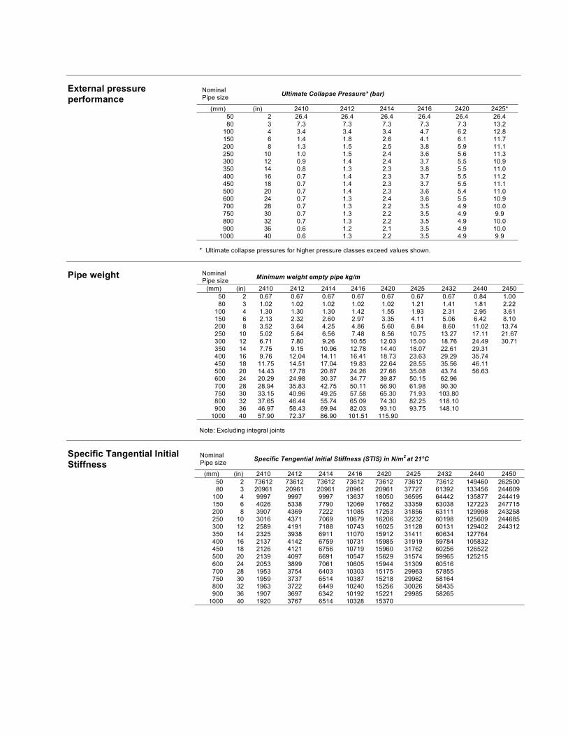
External pressure performance
NominalPipe size
Ultimate Collapse Pressure* (bar)
(mm) (in) 2410 2412 2414 2416 2420 2425* 50 2 26.4 26.4 26.4 26.4 26.4 26.4 80 3 7.3 7.3 7.3 7.3 7.3 13.2
100 4 3.4 3.4 3.4 4.7 6.2 12.8 150 6 1.4 1.8 2.6 4.1 6.1 11.7 200 8 1.3 1.5 2.5 3.8 5.9 11.1 250 10 1.0 1.5 2.4 3.6 5.6 11.3 300 12 0.9 1.4 2.4 3.7 5.5 10.9 350 14 0.8 1.3 2.3 3.8 5.5 11.0 400 16 0.7 1.4 2.3 3.7 5.5 11.2 450 18 0.7 1.4 2.3 3.7 5.5 11.1 500 20 0.7 1.4 2.3 3.6 5.4 11.0 600 24 0.7 1.3 2.4 3.6 5.5 10.9 700 28 0.7 1.3 2.2 3.5 4.9 10.0 750 30 0.7 1.3 2.2 3.5 4.9 9.9 800 32 0.7 1.3 2.2 3.5 4.9 10.0 900 36 0.6 1.2 2.1 3.5 4.9 10.0
1000 40 0.6 1.3 2.2 3.5 4.9 9.9
* Ultimate collapse pressures for higher pressure classes exceed values shown.
Pipe weight NominalPipe size
Minimum weight empty pipe kg/m
(mm) (in) 2410 2412 2414 2416 2420 2425 2432 2440 2450 50 2 0.67 0.67 0.67 0.67 0.67 0.67 0.67 0.84 1.00 80 3 1.02 1.02 1.02 1.02 1.02 1.21 1.41 1.81 2.22
100 4 1.30 1.30 1.30 1.42 1.55 1.93 2.31 2.95 3.61 150 6 2.13 2.32 2.60 2.97 3.35 4.11 5.06 6.42 8.10 200 8 3.52 3.64 4.25 4.86 5.60 6.84 8.60 11.02 13.74 250 10 5.02 5.64 6.56 7.48 8.56 10.75 13.27 17.11 21.67 300 12 6.71 7.80 9.26 10.55 12.03 15.00 18.76 24.49 30.71 350 14 7.75 9.15 10.96 12.78 14.40 18.07 22.61 29.31 400 16 9.76 12.04 14.11 16.41 18.73 23.63 29.29 35.74 450 18 11.75 14.51 17.04 19.83 22.64 28.55 35.56 46.11 500 20 14.43 17.78 20.87 24.26 27.66 35.08 43.74 56.63 600 24 20.29 24.98 30.37 34.77 39.87 50.15 62.96 700 28 28.94 35.83 42.75 50.11 56.90 61.98 90.30 750 30 33.15 40.96 49.25 57.58 65.30 71.93 103.80 800 32 37.65 46.44 55.74 65.09 74.30 82.25 118.10 900 36 46.97 58.43 69.94 82.03 93.10 93.75 148.10
1000 40 57.90 72.37 86.90 101.51 115.90
Note: Excluding integral joints
Specific Tangential Initial Stiffness
NominalPipe size
Specific Tengential Initial Stiffness (STIS) in N/m2at 21°C
(mm) (in) 2410 2412 2414 2416 2420 2425 2432 2440 2450 50 2 73612 73612 73612 73612 73612 73612 73612 149460 262500 80 3 20961 20961 20961 20961 20961 37727 61392 133456 244609
100 4 9997 9997 9997 13637 18050 36595 64442 135877 244419 150 6 4026 5338 7790 12069 17652 33359 63038 127223 247715 200 8 3907 4369 7222 11085 17253 31856 63111 129998 243258 250 10 3016 4371 7069 10679 16206 32232 60198 125609 244685 300 12 2589 4191 7188 10743 16025 31128 60131 129402 244312 350 14 2325 3938 6911 11070 15912 31411 60634 127764 400 16 2137 4142 6759 10731 15985 31919 59784 105832 450 18 2126 4121 6756 10719 15960 31762 60256 126522 500 20 2139 4097 6691 10547 15629 31574 59965 125215 600 24 2053 3899 7061 10605 15944 31309 60516 700 28 1953 3754 6403 10303 15175 29963 57855 750 30 1959 3737 6514 10387 15218 29962 58164 800 32 1963 3722 6449 10240 15256 30026 58435 900 36 1907 3697 6342 10192 15221 29985 58265
1000 40 1920 3767 6514 10328 15370
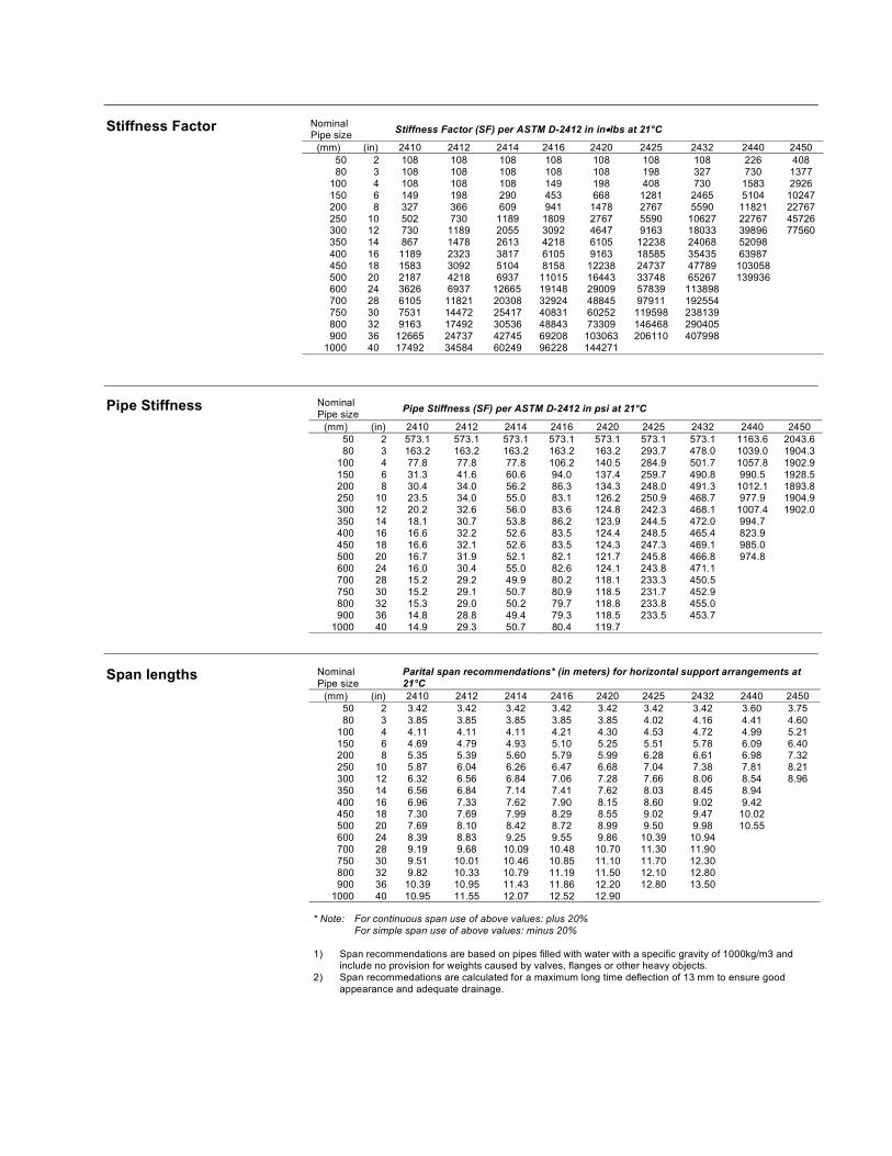
Stiffness Factor Nominal
Pipe size Stiffness Factor (SF) per ASTM D-2412 in in lbs at 21°C
(mm) (in) 2410 2412 2414 2416 2420 2425 2432 2440 2450
50 2 108 108 108 108 108 108 108 226 408 80 3 108 108 108 108 108 198 327 730 1377
100 4 108 108 108 149 198 408 730 1583 2926 150 6 149 198 290 453 668 1281 2465 5104 10247 200 8 327 366 609 941 1478 2767 5590 11821 22767 250 10 502 730 1189 1809 2767 5590 10627 22767 45726 300 12 730 1189 2055 3092 4647 9163 18033 39896 77560 350 14 867 1478 2613 4218 6105 12238 24068 52098 400 16 1189 2323 3817 6105 9163 18585 35435 63987 450 18 1583 3092 5104 8158 12238 24737 47789 103058 500 20 2187 4218 6937 11015 16443 33748 65267 139936 600 24 3626 6937 12665 19148 29009 57839 113898 700 28 6105 11821 20308 32924 48845 97911 192554 750 30 7531 14472 25417 40831 60252 119598 238139 800 32 9163 17492 30536 48843 73309 146468 290405 900 36 12665 24737 42745 69208 103063 206110 407998
1000 40 17492 34584 60249 96228 144271
Pipe Stiffness NominalPipe size
Pipe Stiffness (SF) per ASTM D-2412 in psi at 21°C
(mm) (in) 2410 2412 2414 2416 2420 2425 2432 2440 2450 50 2 573.1 573.1 573.1 573.1 573.1 573.1 573.1 1163.6 2043.6 80 3 163.2 163.2 163.2 163.2 163.2 293.7 478.0 1039.0 1904.3
100 4 77.8 77.8 77.8 106.2 140.5 284.9 501.7 1057.8 1902.9 150 6 31.3 41.6 60.6 94.0 137.4 259.7 490.8 990.5 1928.5 200 8 30.4 34.0 56.2 86.3 134.3 248.0 491.3 1012.1 1893.8 250 10 23.5 34.0 55.0 83.1 126.2 250.9 468.7 977.9 1904.9 300 12 20.2 32.6 56.0 83.6 124.8 242.3 468.1 1007.4 1902.0 350 14 18.1 30.7 53.8 86.2 123.9 244.5 472.0 994.7 400 16 16.6 32.2 52.6 83.5 124.4 248.5 465.4 823.9 450 18 16.6 32.1 52.6 83.5 124.3 247.3 469.1 985.0 500 20 16.7 31.9 52.1 82.1 121.7 245.8 466.8 974.8 600 24 16.0 30.4 55.0 82.6 124.1 243.8 471.1 700 28 15.2 29.2 49.9 80.2 118.1 233.3 450.5 750 30 15.2 29.1 50.7 80.9 118.5 231.7 452.9 800 32 15.3 29.0 50.2 79.7 118.8 233.8 455.0 900 36 14.8 28.8 49.4 79.3 118.5 233.5 453.7
1000 40 14.9 29.3 50.7 80.4 119.7
Span lengths NominalPipe size
Parital span recommendations* (in meters) for horizontal support arrangements at 21°C
(mm) (in) 2410 2412 2414 2416 2420 2425 2432 2440 2450 50 2 3.42 3.42 3.42 3.42 3.42 3.42 3.42 3.60 3.75 80 3 3.85 3.85 3.85 3.85 3.85 4.02 4.16 4.41 4.60
100 4 4.11 4.11 4.11 4.21 4.30 4.53 4.72 4.99 5.21 150 6 4.69 4.79 4.93 5.10 5.25 5.51 5.78 6.09 6.40 200 8 5.35 5.39 5.60 5.79 5.99 6.28 6.61 6.98 7.32 250 10 5.87 6.04 6.26 6.47 6.68 7.04 7.38 7.81 8.21 300 12 6.32 6.56 6.84 7.06 7.28 7.66 8.06 8.54 8.96 350 14 6.56 6.84 7.14 7.41 7.62 8.03 8.45 8.94 400 16 6.96 7.33 7.62 7.90 8.15 8.60 9.02 9.42 450 18 7.30 7.69 7.99 8.29 8.55 9.02 9.47 10.02 500 20 7.69 8.10 8.42 8.72 8.99 9.50 9.98 10.55 600 24 8.39 8.83 9.25 9.55 9.86 10.39 10.94 700 28 9.19 9.68 10.09 10.48 10.70 11.30 11.90 750 30 9.51 10.01 10.46 10.85 11.10 11.70 12.30 800 32 9.82 10.33 10.79 11.19 11.50 12.10 12.80 900 36 10.39 10.95 11.43 11.86 12.20 12.80 13.50
1000 40 10.95 11.55 12.07 12.52 12.90
* Note: For continuous span use of above values: plus 20% For simple span use of above values: minus 20%
1) Span recommendations are based on pipes filled with water with a specific gravity of 1000kg/m3 and include no provision for weights caused by valves, flanges or other heavy objects.
2) Span recommedations are calculated for a maximum long time deflection of 13 mm to ensure good appearance and adequate drainage.
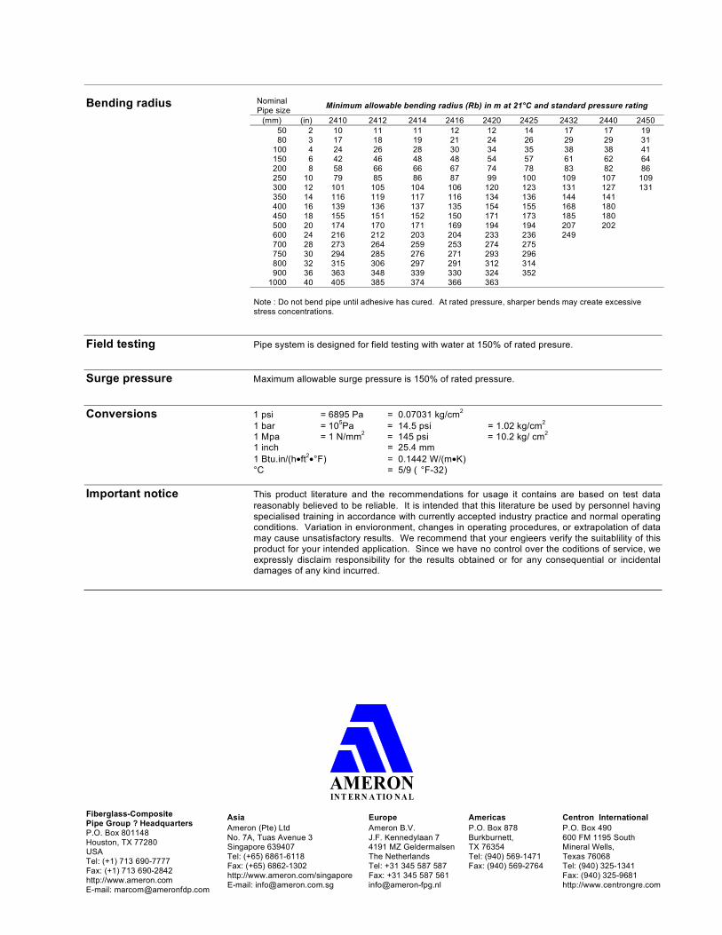
Bending radius Nominal
Pipe size Minimum allowable bending radius (Rb) in m at 21°C and standard pressure rating
(mm) (in) 2410 2412 2414 2416 2420 2425 2432 2440 2450 50 2 10 11 11 12 12 14 17 17 19 80 3 17 18 19 21 24 26 29 29 31
100 4 24 26 28 30 34 35 38 38 41 150 6 42 46 48 48 54 57 61 62 64 200 8 58 66 66 67 74 78 83 82 86 250 10 79 85 86 87 99 100 109 107 109 300 12 101 105 104 106 120 123 131 127 131 350 14 116 119 117 116 134 136 144 141 400 16 139 136 137 135 154 155 168 180 450 18 155 151 152 150 171 173 185 180 500 20 174 170 171 169 194 194 207 202 600 24 216 212 203 204 233 236 249 700 28 273 264 259 253 274 275 750 30 294 285 276 271 293 296 800 32 315 306 297 291 312 314 900 36 363 348 339 330 324 352
1000 40 405 385 374 366 363
Note : Do not bend pipe until adhesive has cured. At rated pressure, sharper bends may create excessive stress concentrations.
Field testing Pipe system is designed for field testing with water at 150% of rated presure.
Surge pressure Maximum allowable surge pressure is 150% of rated pressure.
Conversions 1 psi = 6895 Pa = 0.07031 kg/cm2
1 bar = 105Pa = 14.5 psi = 1.02 kg/cm
2
1 Mpa = 1 N/mm2
= 145 psi = 10.2 kg/ cm2
1 inch = 25.4 mm
1 Btu.in/(h ft2
°F) = 0.1442 W/(m K) °C = 5/9 ( °F-32)
Important notice This product literature and the recommendations for usage it contains are based on test data reasonably believed to be reliable. It is intended that this literature be used by personnel having specialised training in accordance with currently accepted industry practice and normal operating conditions. Variation in envioronment, changes in operating procedures, or extrapolation of data may cause unsatisfactory results. We recommend that your engieers verify the suitablility of this product for your intended application. Since we have no control over the coditions of service, we expressly disclaim responsibility for the results obtained or for any consequential or incidental damages of any kind incurred.
AMERONIN T ER N A TIO N A L
Fiberglass-Composite Pipe Group ? Headquarters P.O. Box 801148 Houston, TX 77280 USATel: (+1) 713 690-7777 Fax: (+1) 713 690-2842 http://www.ameron.com E-mail: [email protected]
Asia
Ameron (Pte) Ltd No. 7A, Tuas Avenue 3 Singapore 639407 Tel: (+65) 6861-6118 Fax: (+65) 6862-1302 http://www.ameron.com/singapore E-mail: [email protected]
Europe
Ameron B.V. J.F. Kennedylaan 7 4191 MZ Geldermalsen The Netherlands Tel: +31 345 587 587 Fax: +31 345 587 561 [email protected]
Americas
P.O. Box 878 Burkburnett, TX 76354 Tel: (940) 569-1471 Fax: (940) 569-2764
Centron International
P.O. Box 490 600 FM 1195 South Mineral Wells, Texas 76068 Tel: (940) 325-1341 Fax: (940) 325-9681 http://www.centrongre.com
AMERON INTERNATIONAL
Bondstrand Guide SpecificationFIBERGLASS - COMPOSITE PIPE GROUP
Bondstrand 2400 Pipe & FittingsFiberglass reinforced thermosetting epoxyresin pipe for plant piping in general service
Scope This specification defines the reinforced thermosetting resin (RTR) piping system to be used in those sections of Plant Piping-General Services calling for fiberglass piping systems.
Reference, References are made to other standards and tests which are a part of this section as modified.
Quality Assurance Where conflict exists between the requirements of this specification and listed references, the specification shall prevail.
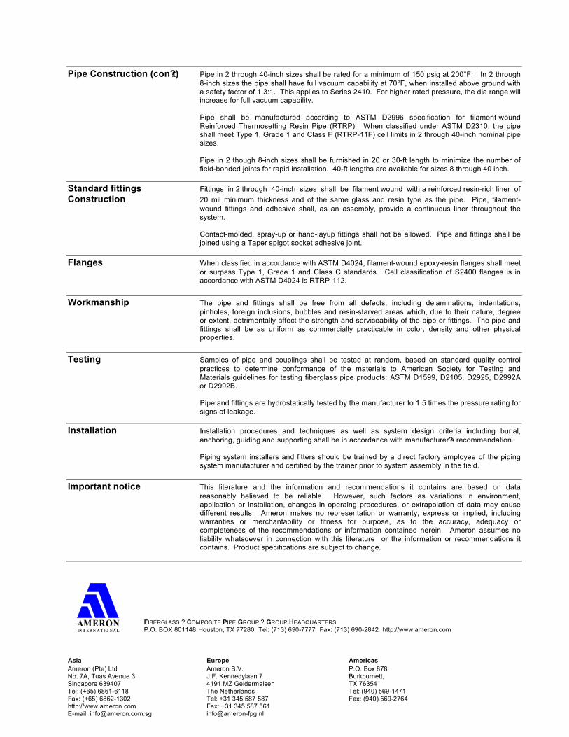
Physical properties Pipe property Units Value Method
Thermal conductivity W(m k) .33 Ameron Thermal expansivity 10
-6 mm/mm/°C 18.0 Ameron
(linear)Flow coefficient Hazen-Williams 150 - Absolute roughness 10
-6 m 5.3 -
Density g/cm3
1.8 -
* Applicable for conductive
Mechanical properties Pipe property Units 21°C 93°C Method
Bi-axial Ultimate hoop stress at weeping N/mm
2 250 - ASTM D-1599
Circumferential Hoop tensile strength N/mm
2 220 - ASTM D-2290
Hoop tensile modulus N/mm2
25200 22100 ASTM D-2290 Poisson?s ratio axial/ hoop - 0.65 0.81 Ameron Longitudinal Axial tensile strength N/mm
2 80 65 ASTM D-2105
Axial tensile modulus N/mm2
12500 9700 ASTM D-2105 Poisson?s ratio hoop/ axial - 0.40 0.44 ASTM D-2105 Axial bending strength N/mm
2 85 - Ameron
Beam Apparent elastic modulus N/mm
2 12500 8000 ASTM D-2925
Hydrostatic Design Basis Static N/mm
2 - 124 ASTM D-2992
(Proc.B.) Cyclic N/mm
2 41.5* - ASTM D-2992
(Proc.A.)
* at 65°C
Performance Pipe shall be manufactured according to ASTM D2996 Specification for RTRP. When classified
Requirements under ASTM D2310, the pipe shall meet Type I, Grade I and Class F (RTRP - 11F) cell limits in 2 through 40 nominal pipe sizes.
Pipe Construction The structural wall of fiberglass pipe in 2 through 40-inch sizes shall have continuous glass fibers wound at a 54¾ helical angle in a matrix of aromatic amine cured epoxy resin.
The integral, reinforced resin-rich liner shall consist of C-glass and a resin/hardener system identical to that of the structural wall, and shall have a 20 mil nominal thickness. Non-reinforced pure resin-type corrosion barriers (liners) shall not be allowed due to their potential for severe fracturing during transportation, installation and operation of the pipe.
Pipe Construction (con?t) Pipe in 2 through 40-inch sizes shall be rated for a minimum of 150 psig at 200°F. In 2 through
8-inch sizes the pipe shall have full vacuum capability at 70°F, when installed above ground with a safety factor of 1.3:1. This applies to Series 2410. For higher rated pressure, the dia range will increase for full vacuum capability.
Pipe shall be manufactured according to ASTM D2996 specification for filament-wound Reinforced Thermosetting Resin Pipe (RTRP). When classified under ASTM D2310, the pipe shall meet Type 1, Grade 1 and Class F (RTRP-11F) cell limits in 2 through 40-inch nominal pipe sizes.
Pipe in 2 though 8-inch sizes shall be furnished in 20 or 30-ft length to minimize the number of field-bonded joints for rapid installation. 40-ft lengths are available for sizes 8 through 40 inch.
Standard fittings Fittings in 2 through 40-inch sizes shall be filament wound with a reinforced resin-rich liner of
Construction 20 mil minimum thickness and of the same glass and resin type as the pipe. Pipe, filament-wound fittings and adhesive shall, as an assembly, provide a continuous liner throughout the system.
Contact-molded, spray-up or hand-layup fittings shall not be allowed. Pipe and fittings shall be joined using a Taper spigot socket adhesive joint.
Flanges When classified in accordance with ASTM D4024, filament-wound epoxy-resin flanges shall meet or surpass Type 1, Grade 1 and Class C standards. Cell classification of S2400 flanges is in accordance with ASTM D4024 is RTRP-112.
Workmanship The pipe and fittings shall be free from all defects, including delaminations, indentations, pinholes, foreign inclusions, bubbles and resin-starved areas which, due to their nature, degree or extent, detrimentally affect the strength and serviceability of the pipe or fittings. The pipe and fittings shall be as uniform as commercially practicable in color, density and other physical properties.
Testing Samples of pipe and couplings shall be tested at random, based on standard quality control practices to determine conformance of the materials to American Society for Testing and Materials guidelines for testing fiberglass pipe products: ASTM D1599, D2105, D2925, D2992A or D2992B.
Pipe and fittings are hydrostatically tested by the manufacturer to 1.5 times the pressure rating for signs of leakage.
Installation Installation procedures and techniques as well as system design criteria including burial, anchoring, guiding and supporting shall be in accordance with manufacturer?s recommendation.
Piping system installers and fitters should be trained by a direct factory employee of the piping system manufacturer and certified by the trainer prior to system assembly in the field.
Important notice This literature and the information and recommendations it contains are based on data reasonably believed to be reliable. However, such factors as variations in environment, application or installation, changes in operaing procedures, or extrapolation of data may cause different results. Ameron makes no representation or warranty, express or implied, including warranties or merchantability or fitness for purpose, as to the accuracy, adequacy or completeness of the recommendations or information contained herein. Ameron assumes no liability whatsoever in connection with this literature or the information or recommendations it contains. Product specifications are subject to change.
FIBERGLASS ? COMPOSITE PIPE GROUP ? GROUP HEADQUARTERS
P.O. BOX 801148 Houston, TX 77280 Tel: (713) 690-7777 Fax: (713) 690-2842 http://www.ameron.com
Asia
Ameron (Pte) Ltd No. 7A, Tuas Avenue 3 Singapore 639407 Tel: (+65) 6861-6118 Fax: (+65) 6862-1302 http://www.ameron.com E-mail: [email protected]
Europe
Ameron B.V. J.F. Kennedylaan 7 4191 MZ Geldermalsen The Netherlands Tel: +31 345 587 587 Fax: +31 345 587 561 [email protected]
Americas
P.O. Box 878 Burkburnett, TX 76354 Tel: (940) 569-1471 Fax: (940) 569-2764
AMERONIN T ERN ATIO N A L