bodywork interface - scaniaedisp/bwm... · • program, save and reuse function connec tions in...
TRANSCRIPT

22:10-019 Issue 2.1 en
Bodywork interface
DescriptionA more detailed description of the electric bodywork interface is found in the docu-ment Installation instructions.
DescriptionBodywork interfaceThe electrical system in Scania vehicles is based on a number of control units that communicate with each other via a common network.
To use existing technology, a bodywork interface is provided which uses traditional (+24 V and ground) and analogue signals. The bodywork interface consists of a num-ber of connections which carry the electrical signals and functions that are available to bodywork.
The basic range in the Scania bodywork interface is presented in this document.
BCI (Bodywork Communication Interface)Scania recommends that a bodywork control unit with functionality with variant code 5837A is ordered as an option. The bodywork control unit provides the follow-ing if 5837A is added:
• An expanded range and selection options regarding signals and functions
• The option of programming a number of outputs with optional signals
• The possibility of remotely controlling certain vehicle functions and access to conditional output signals.
• The possibility of using expansion units to extend the bodywork interface. The expansion unit can, for example, be fitted on the bodywork to minimise the rout-ing of cables into the cab.
• Program, save and reuse function connections in BICT (Bodywork Interface Con-figuration Tool).
• 5837A also provides the possibility of selecting additional functionality, such as, Automatic neutral and Remote engine start.
-GB 1 (19)© Scania CV AB 2015, Sweden
Bodywork interfaceEXT switch
315
587
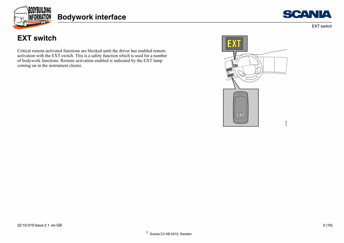
EXT switchCritical remote-activated functions are blocked until the driver has enabled remote activation with the EXT switch. This is a safety function which is used for a number of bodywork functions. Remote activation enabled is indicated by the EXT lamp coming on in the instrument cluster.
© Scania CV AB 2015, Sweden
22:10-019 Issue 2.1 en-GB 2 (19)
Bodywork interfacePreparations from the factory
1
34
5
2
2
350
180
Preparations from the factory
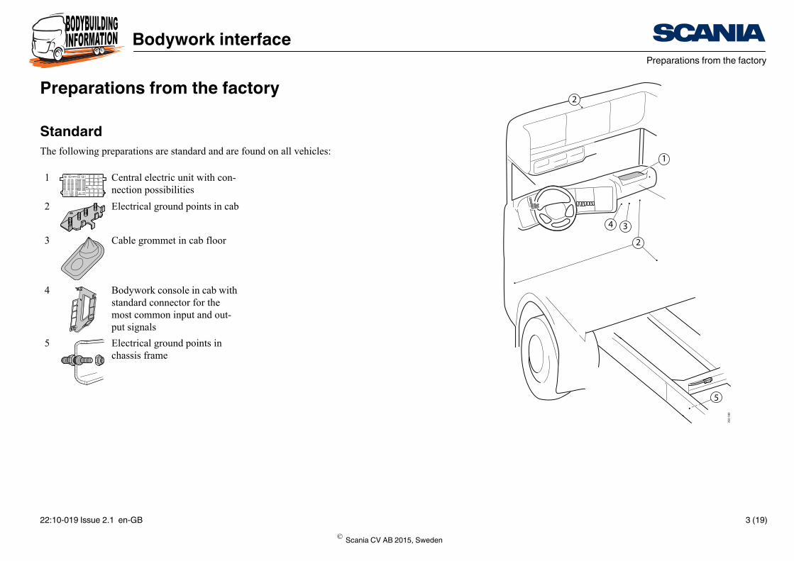
StandardThe following preparations are standard and are found on all vehicles:
1 Central electric unit with con-nection possibilities
2 Electrical ground points in cab
3 Cable grommet in cab floor
4 Bodywork console in cab with standard connector for the most common input and out-put signals
5 Electrical ground points in chassis frame
© Scania CV AB 2015, Sweden
22:10-019 Issue 2.1 en-GB 3 (19)
Bodywork interfacePreparations from the factory
ss for instrument hes
cable harness in ding junction box
cab when the vehi-red)
cable harness from e
cable harness in
nt supply in cab
13
350
184
7
1214
6
11
8
9
10
15
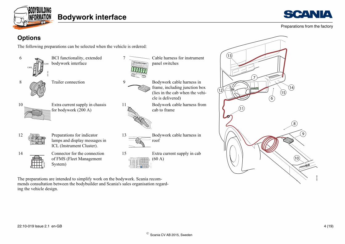
OptionsThe following preparations can be selected when the vehicle is ordered:
The preparations are intended to simplify work on the bodywork. Scania recom-mends consultation between the bodybuilder and Scania's sales organisation regard-ing the vehicle design.
6 BCI functionality, extended bodywork interface
7 Cable harnepanel switc
8 Trailer connection 9 Bodywork frame, inclu(lies in the cle is delive
10 Extra current supply in chassis for bodywork (200 A)
11 Bodywork cab to fram
12 Preparations for indicator lamps and display messages in ICL (Instrument Cluster).
13 Bodywork roof
14 Connector for the connection of FMS (Fleet Management System)
15 Extra curre(60 A)
C493
C259
350
182
1 2 3 4 5 6 7
344
957
350
185
© Scania CV AB 2015, Sweden
22:10-019 Issue 2.1 en-GB 4 (19)
Bodywork interfaceChassis conditions
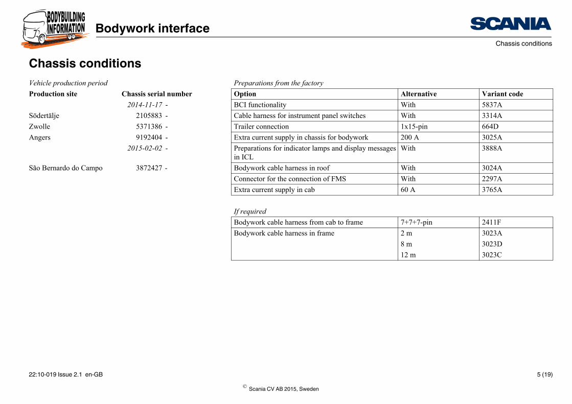
the factoryAlternative Variant codeWith 5837A
instrument panel switches With 3314A
1x15-pin 664D
ly in chassis for bodywork 200 A 3025A
ndicator lamps and display messages With 3888A
arness in roof With 3024A
connection of FMS With 2297A
ly in cab 60 A 3765A
arness from cab to frame 7+7+7-pin 2411F
arness in frame 2 m 3023A
8 m 3023D
12 m 3023C
Chassis conditionsVehicle production period Preparations fromProduction site Chassis serial number Option
2014-11-17 - BCI functionality
Södertälje 2105883 - Cable harness for
Zwolle 5371386 - Trailer connection
Angers 9192404 - Extra current supp
2015-02-02 - Preparations for iin ICL
São Bernardo do Campo 3872427 - Bodywork cable h
Connector for the
Extra current supp
If requiredBodywork cable h
Bodywork cable h
© Scania CV AB 2015, Sweden
22:10-019 Issue 2.1 en-GB 5 (19)
Bodywork interfaceGrounding
314
997
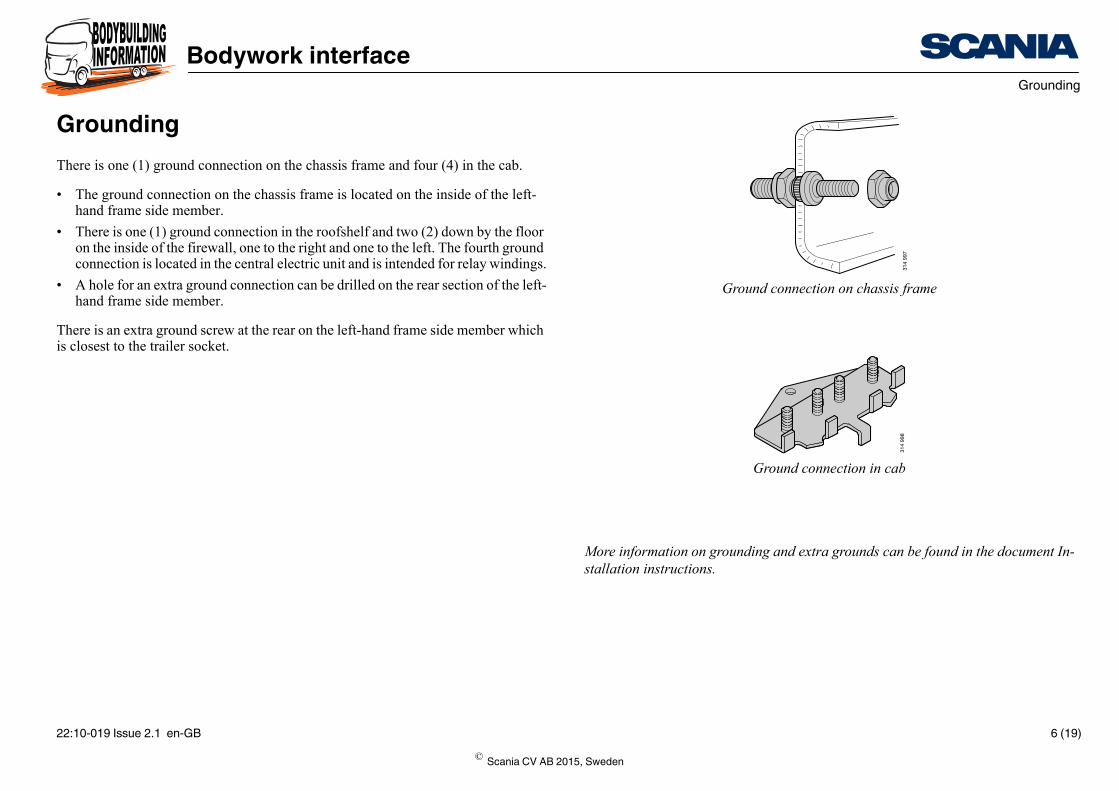
Ground connection on chassis frame
314
998
Ground connection in cab
More information on grounding and extra grounds can be found in the document In-stallation instructions.
GroundingThere is one (1) ground connection on the chassis frame and four (4) in the cab.
• The ground connection on the chassis frame is located on the inside of the left-hand frame side member.
• There is one (1) ground connection in the roofshelf and two (2) down by the floor on the inside of the firewall, one to the right and one to the left. The fourth ground connection is located in the central electric unit and is intended for relay windings.
• A hole for an extra ground connection can be drilled on the rear section of the left-hand frame side member.
There is an extra ground screw at the rear on the left-hand frame side member which is closest to the trailer socket.
© Scania CV AB 2015, Sweden
22:10-019 Issue 2.1 en-GB 6 (19)
Bodywork interfaceCurrent supply
314
999
315
013
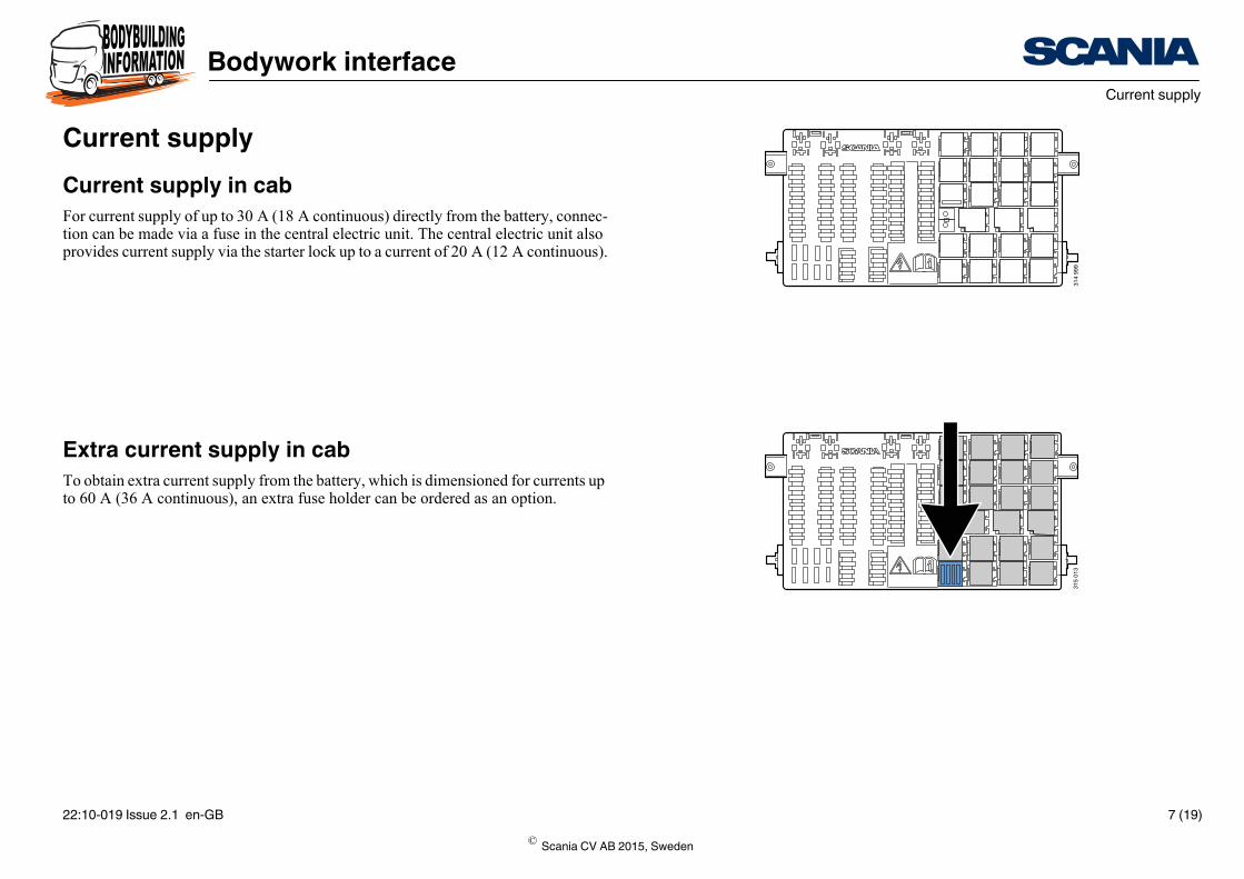
Current supplyCurrent supply in cabFor current supply of up to 30 A (18 A continuous) directly from the battery, connec-tion can be made via a fuse in the central electric unit. The central electric unit also provides current supply via the starter lock up to a current of 20 A (12 A continuous).
Extra current supply in cabTo obtain extra current supply from the battery, which is dimensioned for currents up to 60 A (36 A continuous), an extra fuse holder can be ordered as an option.
© Scania CV AB 2015, Sweden
22:10-019 Issue 2.1 en-GB 7 (19)
Bodywork interfaceCurrent supply
338
694
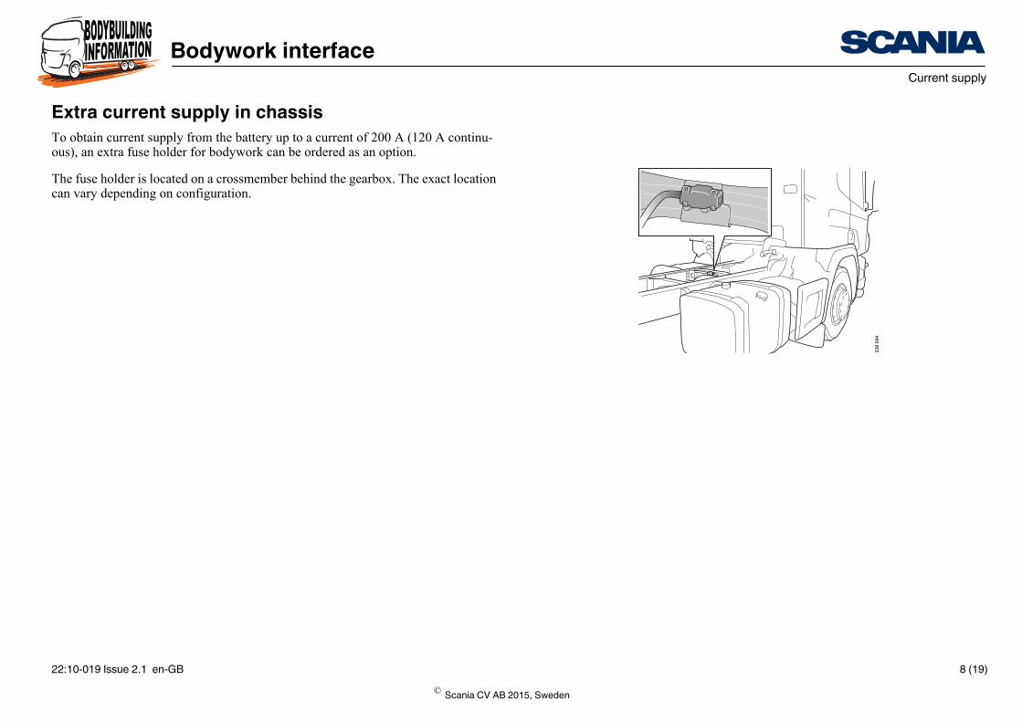
Extra current supply in chassisTo obtain current supply from the battery up to a current of 200 A (120 A continu-ous), an extra fuse holder for bodywork can be ordered as an option.
The fuse holder is located on a crossmember behind the gearbox. The exact location can vary depending on configuration.
© Scania CV AB 2015, Sweden
22:10-019 Issue 2.1 en-GB 8 (19)
Bodywork interfaceCentral electric unit
315
016
15
34
2
315
485
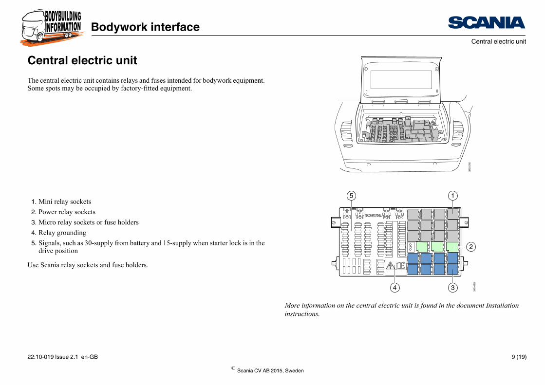
More information on the central electric unit is found in the document Installation instructions.
Central electric unitThe central electric unit contains relays and fuses intended for bodywork equipment. Some spots may be occupied by factory-fitted equipment.
1. Mini relay sockets
2. Power relay sockets
3. Micro relay sockets or fuse holders
4. Relay grounding
5. Signals, such as 30-supply from battery and 15-supply when starter lock is in the drive position
Use Scania relay sockets and fuse holders.
© Scania CV AB 2015, Sweden
22:10-019 Issue 2.1 en-GB 9 (19)
Bodywork interfaceBodywork console
315
486
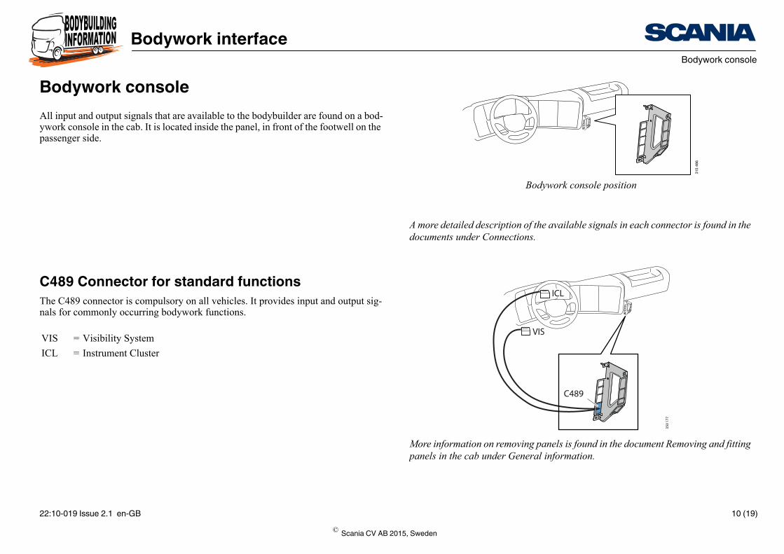
Bodywork console position
A more detailed description of the available signals in each connector is found in the documents under Connections.
C489
ICL
VIS
350
177
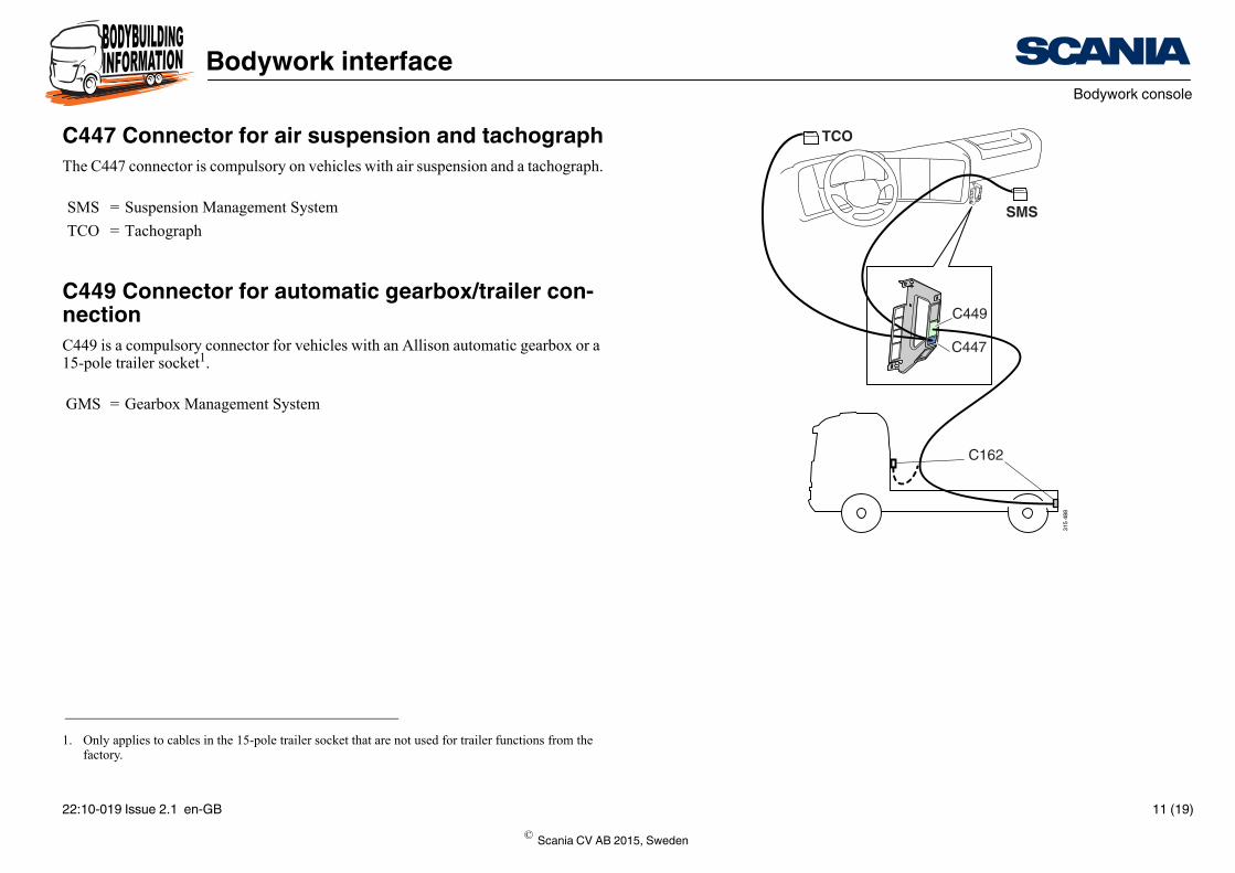
More information on removing panels is found in the document Removing and fitting panels in the cab under General information.
Bodywork consoleAll input and output signals that are available to the bodybuilder are found on a bod-ywork console in the cab. It is located inside the panel, in front of the footwell on the passenger side.
C489 Connector for standard functionsThe C489 connector is compulsory on all vehicles. It provides input and output sig-nals for commonly occurring bodywork functions.
VIS = Visibility System
ICL = Instrument Cluster
© Scania CV AB 2015, Sweden
22:10-019 Issue 2.1 en-GB 10 (19)
Bodywork interfaceBodywork console
C447
TCO
SMS
C449
C162
315
488
C447 Connector for air suspension and tachographThe C447 connector is compulsory on vehicles with air suspension and a tachograph.
C449 Connector for automatic gearbox/trailer con-nectionC449 is a compulsory connector for vehicles with an Allison automatic gearbox or a 15-pole trailer socket1.
SMS = Suspension Management System
TCO = Tachograph
1. Only applies to cables in the 15-pole trailer socket that are not used for trailer functions from the factory.
GMS = Gearbox Management System
© Scania CV AB 2015, Sweden
22:10-019 Issue 2.1 en-GB 11 (19)

Bodywork interfaceBodywork console
More information is found in the document Driver information from bodywork under Electrical system.
C493
C259
C234
ICL 2
BCI
350
178
C493 and C259 Connectors for extended functional-ityWith BCI functionality, extended functionality is provided on connectors C493 and C259.
C234 Indications in ICL for bodywork functionsC234 is used to present status from the bodywork in ICL2. The following functions can be activated in ICL.
• Indicator lamps
• Acoustic indications
• Display messages
ICL2 = Instrument Cluster
© Scania CV AB 2015, Sweden
22:10-019 Issue 2.1 en-GB 12 (19)
Bodywork interfaceBodywork cable harness from cab to frame
C494
C486
C487
C488 344
954
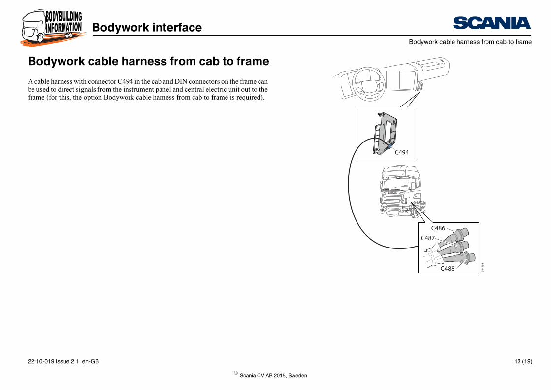
Bodywork cable harness from cab to frameA cable harness with connector C494 in the cab and DIN connectors on the frame can be used to direct signals from the instrument panel and central electric unit out to the frame (for this, the option Bodywork cable harness from cab to frame is required).
© Scania CV AB 2015, Sweden
22:10-019 Issue 2.1 en-GB 13 (19)
Bodywork interfaceBodywork cable harness in frame including junction box
326
964
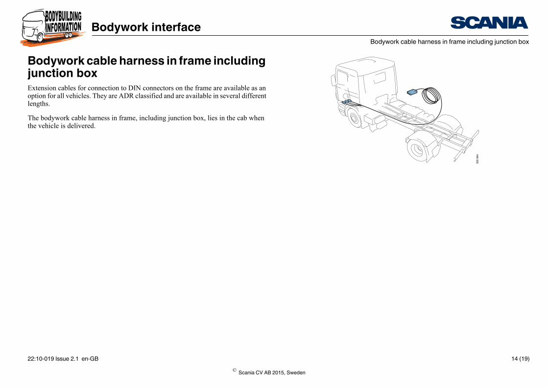
Bodywork cable harness in frame including junction boxExtension cables for connection to DIN connectors on the frame are available as an option for all vehicles. They are ADR classified and are available in several different lengths.
The bodywork cable harness in frame, including junction box, lies in the cab when the vehicle is delivered.
© Scania CV AB 2015, Sweden
22:10-019 Issue 2.1 en-GB 14 (19)
Bodywork interfaceCable grommet in cab floor
315
584
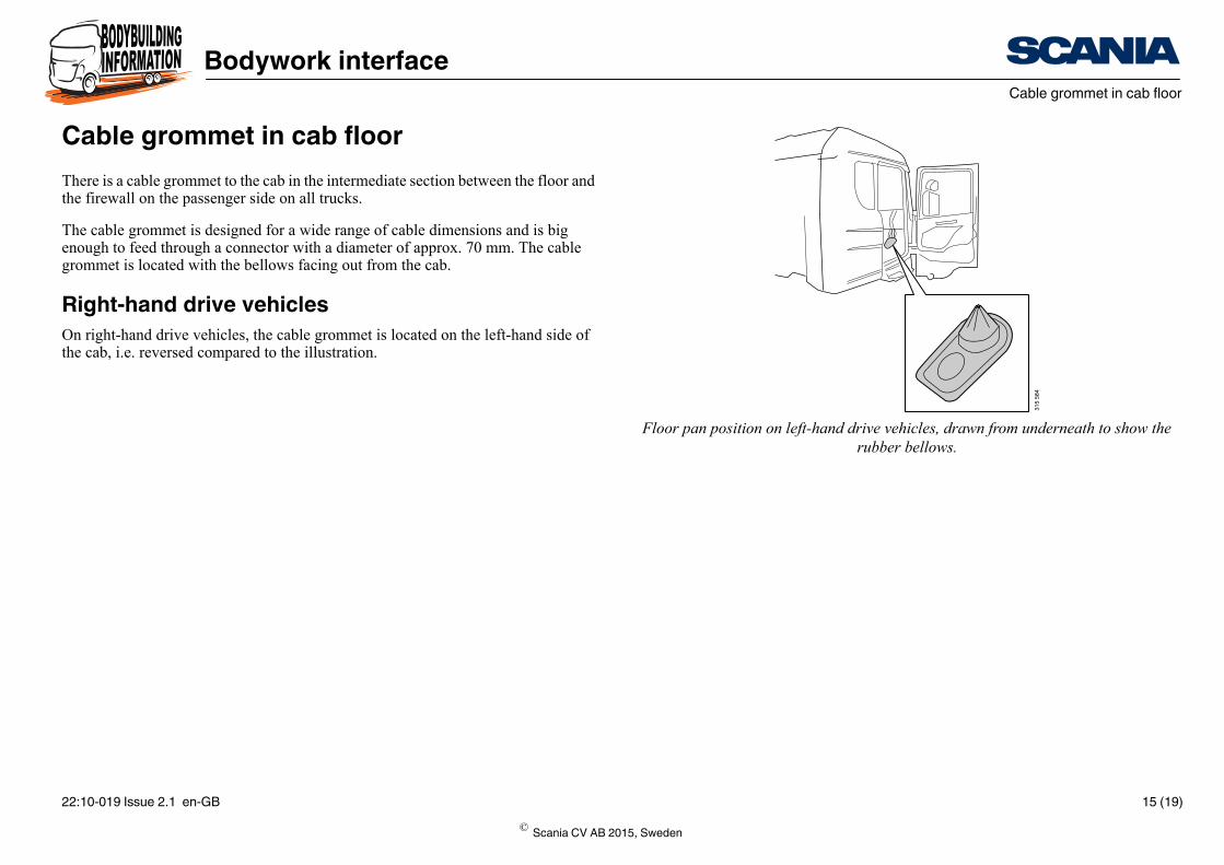
Floor pan position on left-hand drive vehicles, drawn from underneath to show the rubber bellows.
Cable grommet in cab floorThere is a cable grommet to the cab in the intermediate section between the floor and the firewall on the passenger side on all trucks.
The cable grommet is designed for a wide range of cable dimensions and is big enough to feed through a connector with a diameter of approx. 70 mm. The cable grommet is located with the bellows facing out from the cab.
Right-hand drive vehiclesOn right-hand drive vehicles, the cable grommet is located on the left-hand side of the cab, i.e. reversed compared to the illustration.
© Scania CV AB 2015, Sweden
22:10-019 Issue 2.1 en-GB 15 (19)

Bodywork interfaceSwitches
More information on switches can be found in the document Switches for bodybuild-ers
SwitchesSwitches in instrument panelThe space available for bodywork switches in the instrument panel depends on the type of instrument panel and the amount of equipment fitted at the factory.
Cables for connecting additional switches must normally be installed by the body-builder. Prepared cables with connectors for four (4) bodywork switches are availa-ble as an option.
Switches in roofshelfIt is possible to fit switches in the roofshelf depending on what equipment has been fitted at the factory. A cable harness with 10 conductors to the roofshelf, which can be used for connecting the switches, is available as an option.
Switch symbolsThe switches have illuminated symbols which can be connected to a dimmer function for background lighting of switches in the instrument panel.
© Scania CV AB 2015, Sweden
22:10-019 Issue 2.1 en-GB 16 (19)
Bodywork interfaceIndications in ICL for bodywork functions
ICL 2
315
586
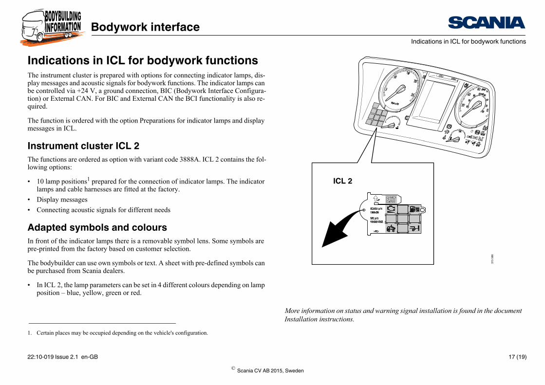
More information on status and warning signal installation is found in the document Installation instructions.
Indications in ICL for bodywork functionsThe instrument cluster is prepared with options for connecting indicator lamps, dis-play messages and acoustic signals for bodywork functions. The indicator lamps can be controlled via +24 V, a ground connection, BIC (Bodywork Interface Configura-tion) or External CAN. For BIC and External CAN the BCI functionality is also re-quired.
The function is ordered with the option Preparations for indicator lamps and display messages in ICL.
Instrument cluster ICL 2The functions are ordered as option with variant code 3888A. ICL 2 contains the fol-lowing options:
• 10 lamp positions1 prepared for the connection of indicator lamps. The indicator lamps and cable harnesses are fitted at the factory.
• Display messages
• Connecting acoustic signals for different needs
Adapted symbols and coloursIn front of the indicator lamps there is a removable symbol lens. Some symbols are pre-printed from the factory based on customer selection.
The bodybuilder can use own symbols or text. A sheet with pre-defined symbols can be purchased from Scania dealers.
• In ICL 2, the lamp parameters can be set in 4 different colours depending on lamp position – blue, yellow, green or red.
1. Certain places may be occupied depending on the vehicle's configuration.
© Scania CV AB 2015, Sweden
22:10-019 Issue 2.1 en-GB 17 (19)

Bodywork interfaceCable harness as option
More information on different cable harnesses for bodywork can be found in the doc-ument Installation instructions.
Cable harness as optionIt is possible to select different cable harnesses from the factory to facilitate work on the bodywork.
© Scania CV AB 2015, Sweden
22:10-019 Issue 2.1 en-GB 18 (19)

Bodywork interfaceExternal CAN, CAN bodywork interface
More information on the CAN interface is found in the CAN bodywork interface doc-ument.
External CAN, CAN bodywork interfaceOne of the main advantages of the bodywork interface is that it allows connection to the vehicle's CAN interface via the bodywork control unit. This enables the body-builder to control functionality by reading information (output signals from the vehi-cle) and sending information (input signals to the vehicle).
Connection point of External CAN for bodywork is done via connector C493. Exter-nal CAN is part of the BCI functionality option and can be ordered from the factory.
Information sent from the vehicle via External CAN includes not only the signals in the existing connectors but also much more. By using the External CAN interface, connections, especially those with multiple functions, can be simplified.
Most functions can be controlled via External CAN.
C137 ConnectorThe FMS standard is an open, common interface developed by several truck manu-facturers. FMS (Fleet Management System).
Connector C137 is located under the central electric unit in the instrument panel.
© Scania CV AB 2015, Sweden
22:10-019 Issue 2.1 en-GB 19 (19)