blue solar pwm pro setup and monitoring software · pdf fileblue solar pwm pro setup and...
TRANSCRIPT

Blue Solar PWM Pro setup and monitoring software
Manual
EN
Appendix


EN
Appendix

Contents
1. Region and language settings 2 2. Download the software 2 3. UnRAR the software 2 4. Install the software 3 5. Install and configure the USB driver 3 6. Establishing communication 7 7. Other settings 12 8. Monitoring more than one controller 18

EN
Appendix
1. Region and language settings (Control Panel > Clock, Language and Region) Different language windows systems have a different character format, therefore the region and language settings must be set to “United States” resp. “English (United States) – US”. These settings can be found under “Region and Language” on the Control Panel of the computer.
2. Download the software Download the software to your PC from the Victron Energy site.
3. UnRAR the software Use WinZip or RarZilla Free Unrar.
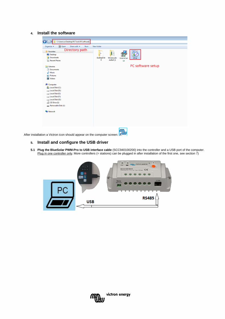
4. Install the software
After installation a Victron icon should appear on the computer screen:
5. Install and configure the USB driver
5.1 Plug the BlueSolar PWM-Pro to USB interface cable (SCC940100200) into the controller and a USB port of the computer. Plug in one controller only. More controllers (= stations) can be plugged in after installation of the first one, see section 7)

EN
Appendix
5.2 Install the USB driver
5.3 Configure (Control Panel > Device Manager > Ports (COM and LPT)
In the Device Manager, double click on the port attributed to the interface cable (XR21B1411). Remember the Port number (in this example it is COM3): it will be needed later (in section 5.1 and 5.5). The properties must be set as shown below:

5.4 Check the box RS-485
Logging in
5.5 Click the “Solar Station Monitor” icon 5.6 The Log in screen will pop up
When logging in as administrator, settings of the controller can be changed and a password is needed. The default password is “111111”. When logging in as guest, settings cannot be changed no password is needed.

EN
Appendix
5.7 After logging in the following screen will appear:

6. Establishing communication with one controller only 6.1 Click the menu “Communication (C)” in the menu bar of the screen shown in section 5.3.
The dialog box “Serial Port Setting” will appear. Enter the correct Port number (see section 3.3) and the correct Baud rate (115200). The Port number must appear under “Configuration” on the right hand side of the dialog box. If needed, click on “Device Manager” to set the correct Data Bits, Stop Bits and Parity. Press “Add”. Press “Update” and close the dialog box.
EN
Appendix
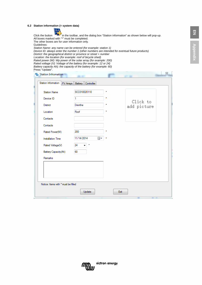
6.2 Station information (= system data)
Click the button in the toolbar, and the dialog box “Station information” as shown below will pop-up. All boxes marked with “*” must be completed. The other boxes are for user information only. Guidelines: Station Name: any name can be entered (for example: station 1) Device ID: always enter the number 1 (other numbers are intended for eventual future products) District: the geographical district or province or street + number Location: the location (for example: roof of bicycle shed) Rated power (W): Wp power of the solar array (for example: 200) Rated voltage (V): Voltage of the battery (for example: 12 or 24) Battery capacity Ah): the capacity of the battery (for example: 60) Press “Update”.
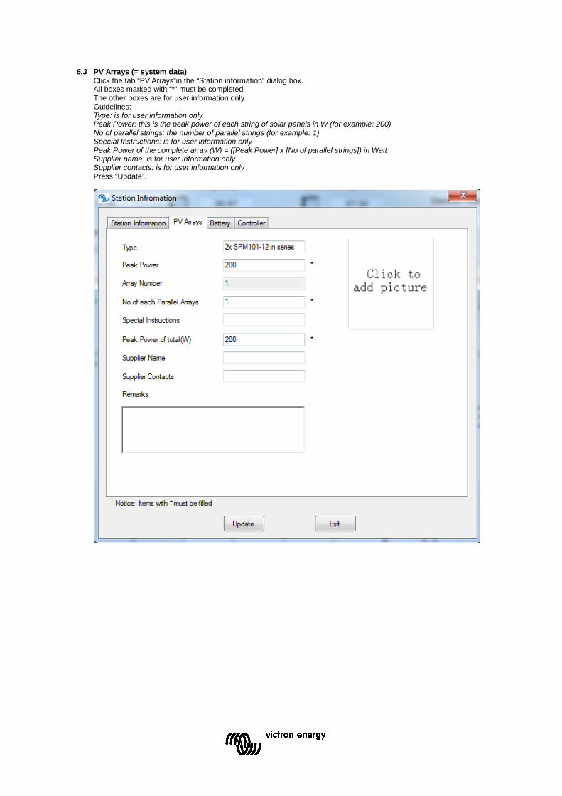
6.3 PV Arrays (= system data) Click the tab “PV Arrays”in the “Station information” dialog box. All boxes marked with “*” must be completed. The other boxes are for user information only. Guidelines: Type: is for user information only Peak Power: this is the peak power of each string of solar panels in W (for example: 200) No of parallel strings: the number of parallel strings (for example: 1) Special Instructions: is for user information only Peak Power of the complete array (W) = ([Peak Power] x [No of parallel strings]) in Watt Supplier name: is for user information only Supplier contacts: is for user information only Press “Update”.

EN
Appendix
6.4 Battery (= system data) Click the tab “Battery” in the “Station information” dialog box. Guidelines: Type: is for user information only (for example: USER, SEALED, GEL, FLOODED) Battery capacity (Ah): already done in tab: “Station information” (section 5.2) Specifications: is for user information only (for example: BAT412550100) Voltage of each battery: is for user information only (for example: 12V) Number of each parallel battery: is for user information only Supplier name: is for user information only (for example: Victron Energy) Supplier contacts: is for user information only Press “Update”.

6.5 Controller (= system data) Click the tab “Controller” in the “Station information” dialog box. Guidelines: Device ID: already done in tab: “Station information” Monitor period: is for user information only Specifications: is for user information only (for example: 12/24V-10A) Rated power: is for user information only (for example: 200) Supplier name: is for user information only (for example: Victron Energy) Supplier Contacts: is for user information only Allow Communication: must be on Port: Select the COM port (for example: COM5). This COM port must be the same as selected in section 3.3 and 4.1 Press “Update” and close the dialog box.

EN
Appendix
6.6 Monitoring (M): Real-time monitoring
Click the button in the toolbar, or Monitoring (M) and the real-time monitoring interface is displayed in the display section of main interface. To start real time monitoring, click the button “Start monitor”.

7 Other settings 7.1 System (F)
[Log Off] To log off from the monitoring software. [User Switch] To switch from Administrator to Guest or from Guest to Administrator. [Change Password] Change Password for the monitoring software. [Add Station] Monitor additional stations. See section 7. [Print Setup] For printing the “Real Time Curve” [Print Preview(V)] For previewing the print of the “Real Time Curve” [Exit(X)] Exit/End the monitoring software
7.2 View(V)
[Tool Bar(T)] Shows or hides the toolbar
Tool Bar [Station Explorer] Shows or hides the Station Explorer on the left side of the screen
[Messages Window] Shows or hides the Messages Window on the bottom of the screen.
7.3 Communication (C)
[Serial port setting] See 5.1
7.4 Parameter (P) [Device Parameters]
[Real Time Clock] Configuring and setting of the internal clock of the Solar Charge Controller
Press “Read” to see the date and time setting of the controller. The date and time setting can be modified by pressing “Update” after setting the correct date and time.

EN
Appendix
[Device Parameter setting] Setting of the internal and external temperature limits. [Device ID Setting]
The ID must be set to “1”
[Control Parameter] Battery settings

The table below shows the list of battery related parameters that can be modified.
Parameter Default setting
Battery type Gel Sealed (AGM)
Flooded User defined
Battery capacity (Ah) 200Ah 1~9999
Temperature compensation coefficient -3mV/°C per 2V cell 0~9
Rated voltage (system voltage) Auto 12V/24V
Over voltage load disconnect 16.0V 9~17V
Charge limit (highest charge voltage including temp. compensation) 15.0V 9~17V
Over voltage load reconnect 15.0V 9~17V
Equalize charge —— 14.6V 14.8V 9~17V
Boost charge (absorption charge) 14.2V 14.4V 14.6V 9~17V
Float charge 13.8V 13.8V 13.8V 9~17V
Boost trigger voltage (starts new charge cycle) 13.2V 9~17V
Low voltage load reconnect 12.6V 9~17V
Under voltage warning reset 12.2V 9~17V
Under voltage warning 12.0V 9~17V
Low voltage load disconnect (nominal value at 25°C) 11.1V 9~17V
Discharge limit (lowest low voltage load disconnect including temp.
compensation) 10.6V 9~17V
Equalize duration —— 2 hrs. 2 hrs. 0~3 hrs.
Boost/absorption duration 2 hrs. 2 hrs. 2 hrs. 0~3 hrs. Multiply voltages by 2 for a 24V system Press “Read” to see the current settings Press “Update” to save the (modified) settings Press “Export Settings” to save settings in a file for later use in another controller Press “Import Settings” to restore the saved settings or import saved settings into another controller
[Load Configuration] Configuration of the Load output

EN
Appendix
Option 1: Manual Control When the load output is set on Manual Control (default setting), the output can be switched ON or OFF with the orange button on the Charge Controller. The low voltage cut-off is also operational. Option 2: Light ON/OFF This is a simple load output ON/OFF option, based on the input voltage of the controller (= output voltage of the solar array).
• When, at dusk, the input voltage of the Controller becomes lower than the light ON voltage (default 0.50 V), the load output is switched on.
• When, at dawn, the input voltage of the Controller becomes higher than the light OFF voltage (default 0.40 V), the load output is switched off.
• In order to prevent unwanted switching a confirmation time (Delay (m)) can be set: default 10 minutes, range 0 – 99 minutes. Option 3: Light ON+Timer This option allows for a pre-set ON-time after dusk and a pre-set OFF-time before dawn. The dusk and dawn switching moments and confirmation time are set as under option 2. The remaining parameters are set as follows:
• Night Time: initial setting of the night duration, the controller will subsequently adjust Night Time to the actual duration of the night.
• On Time 1: ON period after dusk. • On Time 2: ON period before dawn.
Option 4: Time control This option uses the internal clock (see section 6.5) to set one or two ON-time periods.
Press “Read” to see the current settings Press “Update” to save the (modified) settings Press “Export Settings” to save settings in a file for later use in another controller Press “Import Settings” to restore the saved settings or import saved settings into another controller
[System Configuration]
To regularly synchronize the time setting of the charge controller with the PC: choose “not”, every “5” or “10” days and press “SetUp” Temperature unit setting: choose “°C” or” °F” and press “SetUp”

[Device Information]
Press “Read” to display the station name, model, version and serial number
[Factory Operation]
Press Load Test “ON”or“OFF” to test the load output Press “Restore Default” to reset to factory settings Press “Clear Data” to clear all collected data
7.5 Monitoring (M) [Real time Monitoring] See 5.6 [Global Monitoring] Displays a list and status of all connected stations.
7.6 Maintenance (K)
[Export Data] “Export Data “Saves all data to file. [Import Data] “Import Data “Restores all data from file. [Maintenance Record] Text file to record maintenance events.
7.7 Help (H)
[About] There is no online help. See this manual for help

EN
Appendix
8 Monitoring more than one controller In order to keep track of each controller we strongly recommend connecting one controller at a time (by plugging in the interface cable), establish communication and configure it. After completion, proceed with the next controller. Each time, follow the procedure as outlined in section 3.1, 3.3, 5 and 6.

Victron Energy Blue Power Distributor: Serial number: Version : 01 Date : 12 January 2015
Victron Energy B.V. De Paal 35 | 1351 JG Almere PO Box 50016 | 1305 AA Almere | The Netherlands General phone : +31 (0)36 535 97 00 Customer support desk : +31 (0)36 535 97 03 Fax : +31 (0)36 535 97 40 E-mail : [email protected] www.victronenergy.com