surefire ag systems · 396-2861y1 pumpright fertilizer system for case ih pro 700 accucontrol pwm...
TRANSCRIPT

396-2861Y1 PumpRight Fertilizer System for Case IH Pro 700 AccuControl PWM Control 42 Revised 04/01/2015
Pro 700 AccuControl Setup for Liquid PWM Control
Your system may vary from the screens shown here. See the AFS AccuControl Rate
Controller Software Operating Guide for additional information about configuring your
system. The setup may not always happen in the order shown here.
1. Create an Operator (Toolbox > Oper)
2. Check GPS Status (Toolbox > GPS)
3. Create Implement (Toolbox > Impl)
4. Set up Product (Toolbox > Product)
5. Set up Container (Optional) (Toolbox > Container)
6. Basic Setup (Toolbox > AccuCtrl)
A. Select AccuCtrl Operation (Liquid)
B. Select AccuCtrl Installed (Yes)
C. Select Implement Type (Liquid Toolbar)
1
12
7. Implement Configuration (Toolbox > AccuCtrl >
Imp Config)
A. Press ‘Setup’
B. Select Drive Type (will be Hydraulic Drive)
C. Select Vehicle Type
D. Set Number of Drive Sections (A) Always = 1
E. Pump Type will be set at Centrifugal
F. Set Total Number of Rows (B)
G. Enter Row Width (C)
H. Enter Bar Distance in Inches (axle to knife) (D)
I. Measure Implement Right/Left Offset
J. Scroll down to Enter Rows per Drive Section (same as Total Number of Rows)
K. Press ‘Done’
8. Section Control Setup (If equipped with
Section Shutoff Valves) Toolbox > AccuControl > Section Control
A. Select Section Control (Yes)
B. Press ‘Setup’
C. Assign Module Serial Numbers
D. Assign Rows per Output (number of rows per
Section)
E. Select Control Polarity (Active On)
F. Select ‘Done’
9. Overlap/ Boundary Control (Toolbox > Overlap)
A. Turn Overlap Control and Boundary Control ON.
B. Adjust values as desired. Sure
Fire Ag S
ystem
s

396-2861Y1 PumpRight Fertilizer System for Case IH Pro 700 AccuControl PWM Control 43 Revised 04/01/2015
10. Liquid Drive Setup Toolbox > AccuControl > Liquid
Drive
A. Select Liquid Drive (Yes)
B. Press ‘Setup’
C. Assign Liquid Drive Serial Numbers
D. Select Drive Type (PWM)
E. Select Master Valve Type (NO)
F. Select Pump Disarm (No)
G. Select Sec Off Behavior (Turn Off)
H. Enter Drive Meter Cal Number (3000 pulses/gal for
electric systems; 2000 pulses/gal for hydraulic systems)
I. Press ‘Done’
11. Master Switch Box (If equipped with External Switch Box)
A. Select Master Sw Box (Yes or No)
B. Press ‘Setup’
C. Verify Serial Number
D. Select Foot Swiitch (if installed)
E. Press ‘Done’
12. Implement Switch (if installed)
A. Select Imp Switch (Yes)
B. Press ‘Setup’
C. Select Imp Switch Serial Number
D. Select Switch Polarity (Determine this by raising and lowering the implement and watch the Implement Status Arrow in Status/
Warning Area for proper operation.)
E. Press ‘Done’
13. Section Switch Box (If system is equipped with External Section Switch Box or desire Manual Valve Section Control through Run Screens).
A. Select Section Switch Box (Yes)
B. Press ‘Setup’
C. Select Config Mode (Auto)
D. Verify Sw Box Serial Number (if equipped)
If no external switchbox is installed, User Defined Windows can be assigned to a Run Screen (Toolbox>Layout).
AccuControl Setup for Liquid
Optional Master Switch Box and Foot Switch
2000
SureFire
Ag Sys
tems

396-2861Y1 PumpRight Fertilizer System for Case IH Pro 700 AccuControl PWM Control 44 Revised 04/01/2015
Create A LayoutGo to Toolbox>Layout
Select Current Layout and then select New.
Name the Layout. Under Run Screen select a screen.
In the white boxes consider adding the following items
to a Run Screen:
AccuControl Speed
Master Control
Liquid Op Mode
Liquid Control
Liq App Rate Scan Container
Liq Flow Rt Scan
Section Control
Overlap Ctrl Overlap Control
Clutch Control (may want this if the system has
electric section valves)
The Run Screen Layout is largely a matter of operator preference. Some of these items may be added to the
Left Hand Area if space is available there, or more than one Run Screen can be set up.
Valve Calibration
Work Condition > Valve Cal > Advanced Valve CalibrationThe electric pump systems typically run well with the following default settings. There is more variation in
hydraulic pump systems. The Valve Calibration procedure may give you the best settings for a hydraulic
pump system. It may also give some settings that don’t work well at times. Try the following default values as
a starting point and make adjustments as needed for your system.
See the pictures on the following pages for other values.
Additional Tips for Getting Started 1. Set the Flow Error Timeout at 30—45 seconds until you get the system adjusted and operating correctly. The default is 5 seconds. This may result in the application being shut down before you have a chance to see how it is operating. After the system is operating correctly, this can be set lower to give you a quicker warning if something is wrong. (Work Condition > Valve Cal > Advanced Calibration > Scroll down to 2nd page and Flow Error Timeout)2. Set the Fault Speed to Slow or Off until you get the system adjusted and operating correctly. The default is Normal. (Work Condition > Operate > Fault Speed) After the system is operating correctly, this can be set back to Normal. You can run this at Slow if the system gives too many Fault Warnings at Normal.3. See page 65 for instructions on running Liquid Cal for initial setup.
IntegralGain
Breakout DeadZone Integrator
Upper Limit
Integrator Lower Limit
Comparator Limit
Electric 0.5 3 2 100 -100 100
Hydraulic 0.2 10 2-3 100 -100 100
SureFire
Ag Sys
tems
396-2861Y1 PumpRight Fertilizer System for Case IH Pro 700 AccuControl PWM Control 45 Revised 04/01/2015
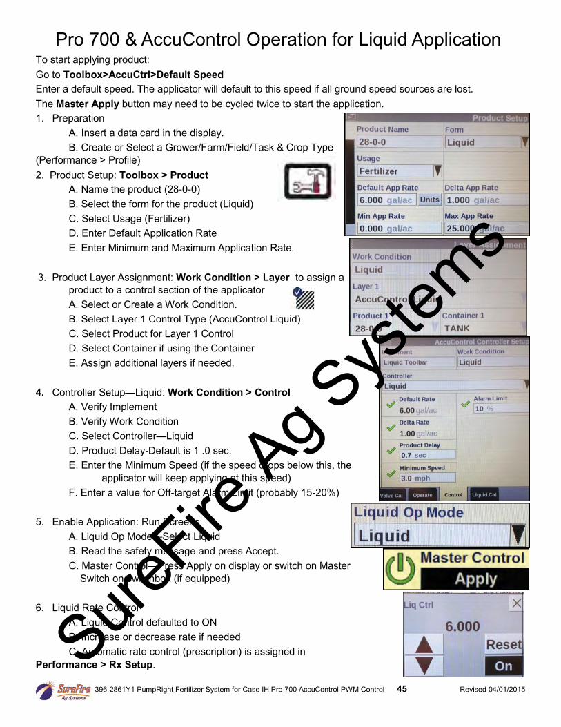
Pro 700 & AccuControl Operation for Liquid Application To start applying product:
Go to Toolbox>AccuCtrl>Default Speed
Enter a default speed. The applicator will default to this speed if all ground speed sources are lost.
The Master Apply button may need to be cycled twice to start the application.
1. Preparation
A. Insert a data card in the display.
B. Create or Select a Grower/Farm/Field/Task & Crop Type
(Performance > Profile)
2. Product Setup: Toolbox > Product
A. Name the product (28-0-0)
B. Select the form for the product (Liquid)
C. Select Usage (Fertilizer)
D. Enter Default Application Rate
E. Enter Minimum and Maximum Application Rate.
3. Product Layer Assignment: Work Condition > Layer to assign a
product to a control section of the applicator
A. Select or Create a Work Condition.
B. Select Layer 1 Control Type (AccuControl Liquid)
C. Select Product for Layer 1 Control
D. Select Container if using the Container
E. Assign additional layers if needed.
4. Controller Setup—Liquid: Work Condition > Control
A. Verify Implement
B. Verify Work Condition
C. Select Controller—Liquid
D. Product Delay-Default is 1 .0 sec.
E. Enter the Minimum Speed (if the speed drops below this, the
applicator will keep applying at this speed)
F. Enter a value for Off-target Alarm Limit (probably 15-20%)
5. Enable Application: Run Screens
A. Liquid Op Mode—Select Liquid
B. Read the safety message and press Accept.
C. Master Control—Press Apply on display or switch on Master
Switch on switchbox (if equipped)
6. Liquid Rate Control
A. Liquid Control defaulted to ON
B. Increase or decrease rate if needed
C. Automatic rate control (prescription) is assigned in
Performance > Rx Setup. SureFire
Ag Sys
tems

396-2861Y1 PumpRight Fertilizer System for Case IH Pro 700 AccuControl PWM Control 46 Revised 04/01/2015
Possible Run Screen Layout for system with 2 electric
section valves
Screen showing Flow Error Timeout set to 45 sec Work Condition > Valve Cal > Advanced Calibration > Scroll down to 2nd page and Flow Error Timeout)
Start with these Valve Cal settings
Work Condition > Valve Cal > Advanced Calibration
(For Hydraulic pumps)
Screen showing AccuControl Liquid Drive Setup
Toolbox > AccuCtrl > Lquid Drive Setup
To use default AccuCtrl speed, turn Radar off.
0.3
10
2
2000
SureFire
Ag Sys
tems
xx 0.18 TO 0.20

396-2861Y1 PumpRight Fertilizer System for Case IH Pro 700 AccuControl PWM Control 47 Revised 04/01/2015
Container Setup (Sample) Toolbox > Contnr
Fault Speed, Beeps, etc... Work Condition > Operate
Implement Setup (Sample) Toolbox > Impl
Your system setup may vary from the screenshots shown here. There may be other setup items that need to be completed for your system. Your system may not require all the setups shown here. See the manuals from Case IH for the Pro 700 display and for AFS AccuControl for more information about setup and operation of your system. If the suggested Valve Cal numbers don’t work, try running the Valve Calibration procedure at Work Condition > Valve Cal.
SureFire
Ag Sys
tems

396-2861Y1 PumpRight Fertilizer System for Case IH Pro 700 AccuControl PWM Control 48 Revised 04/01/2015
SureFire
Ag Sys
tems
IMPORTANT: SOFTWARE VERSION AND RATE & SECTION CONTROL MODULE UPDATES
Keep your software up-to-date. Go to Diagnostics > Version to see the Software Version number for each piece of software( esp. AccuControl). Check with your CASE(NH) dealer to see what the latest versions are. Also, check and update the software/firmware for the Field-IQ module (Diagnostics > CAN > Scroll to find Rate & Section Control Module). Have dealer update all this once a year. March 2017--Display and AccuControl version 30.16. Rate & Section Ctrl Module should be 3.19. Version 2.14 will NOT work.
For Initial Operation run Liquid Cal procedure described on page 65.

396-2861Y1 PumpRight Fertilizer System for Case IH Pro 700 AccuControl PWM Control 49 Revised 04/01/2015
G Trouble-shooting
Pump Will Not Turn
Turn hydraulics off, go to the SureFire PWM valve and use the manual override on top of the electric coil to manually open the valve (Manual Override UP = valve fully open. Push down on the red knob, turn a half turn to the left, it should come up. If you can’t push it down, it is probably packed with dirt and will need to be cleaned out.). Turn hydraulics on at a low flow only as the valve is 100% open. If the pump doesn’t turn, try hydraulic lever in opposite direction or reverse the hoses. Try a different remote. Does the pump turn? If pump is running now, your problem is electric / electronic. If the pump still does not turn, you have a hydraulic problem.
Electric / Electronic Problem
See the next 2 pages for additional
instructions:
1. Close manual override (lock down).
2. Verify hydraulics are on.
3. Make sure you have a Default Speed setup. Set Flow Error Timeout to 45 seconds.
4. Press Master Control-Apply to start pump.
5. Take a metal object and hold it next to thecoil. If the coil is working, you will feel themagnetic pull.
6. If no magnetic force is felt, disconnect thePWM valve connector and check voltage.You will need 7-13 volts to get hydraulicvalve to open.
7. If 7-13 volts is not present, checkharnesses and review control valve typesetup.
8. Go back to the 30-pin connector at theField-IQ Rate and Section Control Module.Check voltage between pins E1 & E2,should be between 7-13 volts while insection test after holding increase button.
9. If you cannot get voltage at pins E1 & E2,contact your Trimble dealer for furtherassistance.
Troubleshooting
Hydraulics Problem
1. Leave the manual override open on theSureFire valve.
2. Check the hose routings. The “P” port onthe SureFire valve should hook topressure. The “T” port is the return thatshould flow back to the tractor.
3. Try hoses in a different hydraulic remote.Inspect hydraulic connectors for damageor restrictions.
Hydraulic Manual Override Down - Normal Operation Up - Override, valve 100% open
SureFire
Ag Sys
tems

396-2861Y1 PumpRight Fertilizer System for Case IH Pro 700 AccuControl PWM Control 52 Revised 04/01/2015
Application Rate Fluctuates Inspect & clean pump inlet strainer. Strange flow rate fluctuations are very often due to an obstruction to the pump inlet. Inspect plumbing from tank to pump.
You need to determine if the fluctuation is caused by the controller sending fluctuating signals to the valve.
OR
1. Turn the system on in Manual mode and watch the flow in GPM.
2. Is the flow steady within a very small range? For example a fluctuation from 2.3 to 2.5 GPM would beconsidered normal. A fluctuation from 2-3 GPM is a problem. If only a small normal fluctuation is seen,skip steps 4-8 and proceed to “Application Rate Fluctuates in Field …….. “ below.
3. If there is a large fluctuation, observe the system flow. Is the discharge a steady stream; are the flowindicator balls floating steady?
4. If visually the flow is steady, but the display reports a fluctuation in GPM, inspect the flowmeter. Seesection B for flowmeter information.
5. If visually the flow is unsteady, the flowmeter is working correctly reporting a flow problem. Is the pumpturning steady or surging? If the pump is surging reduce the PWM gain in controller settings.
6. Look for any type of obstruction in the pump inlet. Clean the strainer. If continually plugging the strainerinvestigate fertilizer quality and necessary strainer size.
Troubleshooting G Trouble-shooting
Application Rate fluctuates in field, but flow in manual mode is stable. This problem indicates the PWM gain needs changed. The system is surging because the Control Module is “hunting” for the correct flow.
1. Go to Work Condition > Valve Cal > Advanced Calibration.
2. Change the settings by reducing the Integral gain.
Application Rate is slow to get to the Target Rate 1. You may need to increase the Gain setting. Go to Work Condition > Valve Cal > Advanced Calibration.
2. Change the settings by increasing the Integral gain.
No Flow shown on display but liquid is being pumped 1. Unplug flowmeter. With voltmeter, check for 12 volts between pins B&C of flowmeter connector (on main
harness PN 215223Y2). If 12 volts not present, inspect wiring harness and troubleshoot all connectionsper schematic (see Section D).
2. If 12 volts is present, then conduct a tap test. Go to setup and change the flow cal to 20. Have a secondperson watch GPM on the display while other person taps (use a short piece of wire or a paper clip)between pins A&C of flowmeter connector (on 215223Y2 harness). A flow value should show upindicating the wiring is not damaged.
3. If flow display responded to the tap test, your wiring to that point is good. If still not fixed, inspect adapterharness and test continuity per schematic (see Section D).
4. Replace flowmeter.SureFire
Ag Sys
tems

396-2860Y1 SureFire Tower for Case Pro 700 and AccuControl-PWM Control 65 Revised 03/31/2016
Addendum to 396-2860Y1 and 396-2861Y1 Setup and Troubleshooting the Pro 700 AccuControl Liquid PWM System (aka Intellivew IV Intellirate) Note to SureFire people: The Default speed setting that works on our test stand does not work when the tractor is not moving when the Pro 700 is plugged into a tractor that has Radar, Wheel, or GPS speed capability. This makes testing the system in a Run mode impossible without driving the tractor. Use the method below, instead. On our test stand, set the Default Speed to 0 (Toolbox > AccuCtrl > Default Speed > 0) before doing this.
To test the Pro 700 AccuControl on initial startup and in a troubleshooting situation, use the Liquid Cal mode. (Work Condition > Liquid Cal)
1. Set up the Toolbox > AccuControl configuration page so all AccuControl items are set.
2. Set up the Work Condition > Valve Cal > Advanced Calibration screen to match the settings shown in the manual forTower (3/3/2016 manual or later) or PumpRight systems. The Valve Calibrationprocedure is likely to give results that will not work. It may be fairly good exceptfor an Upper Integrator Limit that is too low, or it may have totally unworkablenumbers in Dead Zone and other fields.
3. Set the Flow Error Timeout (on page 2 of the Valve Calibration setup) to 45sec. This will let the system run for a while before it shuts down if it is notdetecting flow.
4. Go to Work Condition > Liquid Cal
5. If the Prime button does not show up here:
Home > Toolbox > AccuControl > Imp Config > Setup > Scroll down >Liquid Prime > Enabled. (Pressing the Prime button will run the pumpfor 10 seconds. To keep the pump running, press and hold the Prime button.)
6. To run the system from here with a simulated speed and target rate:
Liquid Op Mode > On Master Control > Apply > Next
7. Enter a Simulated Speed and Target Rate (these can be changed whilerunning in this mode to test other speeds or rates). Press Next.
8. Press Start to start the pump.System should run at Simulated Speedand Target Rate. Measured Outputshould count up as product is pumped.To see actual flow in gpm, you need toset up a Layout for the Left Area withLiq Flw Rt Scn. This is very usefulwhen diagnosing pump or systemissues. It needs to be in the Left Area
so you can see it while running in this mode. (Remember, when testing with water, the pressure will be much less than it will be with a fertilizer product. If the pressure is too low, all the rows may not flow because there may not be enough pressure to open all the check valves. Increase the rate until all rows are flowing.)
9. If the pump does not run here, perform the other troubleshooting tests for hydraulic or electric pumps. You can startthe system here and use a voltmeter to verify that there is PWM voltage at the EPD or hydraulic valve. (If it is notreading flow, it will quickly ramp up to maximum pump speed and shut off, giving a “Motor Stalled” error message.To make this happen more slowly, set the Integral Gain to 0.1 to allow time for diagnostic observation.)
10. If the pump runs and liquid is flowing but no flow is showing in the Liq Flw Rt Scn box, check for 12 v at theflowmeter connection (pins B & C) and do a tap test (pins A & C) to see if flow will register on the display (see note in#9 about setting Integral Gain).
11. If the pump runs, but is surging, lower the Integral Gain. If it is pumping, but getting to rate very slowly, raise this.
12. If the system has section valves, they should open when this test is started. If they don’t open, check theAccuControl Configuration setup (Toolbox > AccuControl > Section Control > Setup {should have green checkmarks,Control Polarity is Active On}). Check Section Sw Box Setup > Config Mode > Auto (should say Run Screen in upperright corner). Set up a Run Screen layout with Clutch Control 2X2 to have section switches on the display. Be sureBoundary Control and Overlap Control are ON (Toolbox > Overlap). If they still don’t open, check for constantvoltage (pins A&B) and signal voltage (pins B&C) at valve.
SureFire
Ag Sys
tems