bharat heavy electricals · pdf filetype of doc. technical ... purchaser bharat heavy...
TRANSCRIPT

E ; E
4 0
<:
U !a C
> g Q S a ~ 2 : e 2 g 5 % E g g g n a < gs 5 2 g 2;: 8 5 u g *
0 G " g 5 v c v
:; 8 9 g 2 cr - 5 2
E 8 =
BHARAT HEAVY ELECTRICALS LIMITED TRANSMISSION BUSINESS ENGINEERING MANAGEMENT
Prepared
A A
sd-
TBEM
NAME
SIGN
DATE
GROUP
DOCUMENT No.
CUSTOMER
PROJECT
CANo.
STATION
Checked
VK
sd-
W.O. No
Rev. NO. TB-343-558-037
POWER GRID CORPORATION OF INDIA LIMITED (POWERGRID)
*00KV, 6000MW, HVDC MULTI-TERMINAL NERIER- N W R INTERCONNECTOR-I PROJECT
C-61901R-S056-8lCA-IY3660 dated 22.11.2011 for on-shore Supplies C-61901R-S056-8lCA-IVl3662 dated 22.11.2011 for Services
AGRA, BISWANATH CHARIALI & ALIPURDUAR
Approved
RS
Sdl-
80014
0 1
TYPE OF DOC. TECHNICAL SPECIFICATION
CONTENTS
TITLE
VIDEO PROJECTION SYSTEM
Section
1
'2
3
1
Rev No.
Description
Scope, Technical Requirements & Bill of Quantity
Equipment Specification
General Technical Requirements-
Doc No. TR343-316-000
No. of Sheets
06
02
0 1
Copies
Date
2
, Altered
3
Distribution
1
\'*Q Checked
A BB
I 3 - A
\ Approved
n *I vised as per PGCIL comments dated
3 2 z 2 - 2 0 1 2 REVISION DETAILS
PGCIL TBEM
&800KV, 6000MW, HVDC MULTI-TERMINAL NERlER - NRIWR INTERCONNECTOR-I PROJECT
VIDEO PROJECTION SYSTEM
Doc. No. : TB-343-558437, Rev. 01
SECTION - 1
SCOPE, SPECIFIC TECHNICAL REQUIREMENTS AND QUANTITIES
1.1 SCOPE
This specification is intended to specify the requirements for design, engineering, manufacture, assembly, testing, supply, transport, installation and testing at site of Video Projection System along with its accessories as mentioned in this section and in various other sections of this specification. The equipment is required for f 800 KV, 6000 MW HVDC Multi-terminal System Package ccjmprising three Switchyards at Biswanath Chariali, Alipurduar & Agra.
In case of any conflict among the various sections of this specification, then the order of precedence shall be Section-1, Section-2 & then Section -3.
1.2 PROJECT DETAILS
The equipment is required for the following project
Project tile +_800KV, 6000MW, HVDC MULTI-TERMINAL NER/ER - NR/WR INTERCONNECTOR-I PROJECT
Owner1 Employer Power Grid Corporation of India Limited (POWERGRID)
Purchaser Bharat Heavy Electricals Limited (BHEL)
Refer Section - 3 for Project Details and General Specifications
1.3 SPECIFIC TECHNICAL REQUIREMENTS
1.3.1 The Video Projection System (VPS) shall provide comprehensive overview of the entire HVDC and AC system to facilitate control and monitoring of the station from operator work station (OWS).
1.3.2 The VPS shall have all the facilities for integrating multi- terminal parallel valve groups controls such that in future multi- terminal parallel valve groups at these converter stations shall be operated and monitored from common station operator desk & VPS. Station operator desk & Main VPS shall be located on First floor. Back up station Operator & Back up VPS shall be installed at Second Floor for AGRA. PGCIL has the freedom to decide the number of OWS to place on Main and standby operator desk respectively out of the total delivery made at AGRA.
1.3.3 The Video Projection system shall have interface with the following at each convertor station: a) Three (3) operator work station (OWS) for HVDC control with two monitors each. b) One (1) operator work station (OWS) for Building management system (BMS) with one
monitor. c) One (1) operator work station (OWS) for Existing Substation Automation System with one
monitor. d) Video Conferencing System. e) CCTV System
Page 2
UOOKV, 6000MW, HVDC MULTI-TERMINAL NEWER - NRIWR INTERCONNECTOR-1 PROJECT
VIDEO PROJECTION SYSTEM
Doc. No. : TB-343-558437, Rev. 01
1.3.4 Each OWS for HVDC control consists of two monitors (3840 * 1080 pixels in total). OWS for all other functions will have a single monitor, Each of their CPU will have two (2) Nos DVI-D output ports for its further use by VPS supplier.
1.3.5 Video output signal (Composite video/S-video signals) from the video conferencing system and Video output signal from CCTV system shall be made available for its use by the VPS supplier.VPS offered shall have adequate provision for Video-In signals.
1.3.6 UPS with a battery back-up of 30mins shall be available for VPS. The VPS supplier shall furnish the loads and other details for sizing this UPS. BHEL shall make the raw UPS power supply available near VPS at each floor. The arrangement to receive the raw UPS supply and it's further distribution shall be in the scope of VPS supplier. This shall include supply of distribution cables1 wires and distribution/ extension boards by the VPS supplier. The estimation of the distribution cables1 wires and number of distribution1 extension boards shall be done by the VPS supplier as per the site requirement.
1.3.7 The licensed software alongwith the server PC shall be supplied by the VPS supp!ier for each converter station.
1.3.8 The supply of all the special cables viz., DVI cables, STP cables, Network cables etc connecting all the offered equipments amongst themselves and with their source (OWS and Video conferencing equipment) is in the scope of VPS supplier. The length of special cables shall be evaluated by the VPS supplier as per the site requirement.
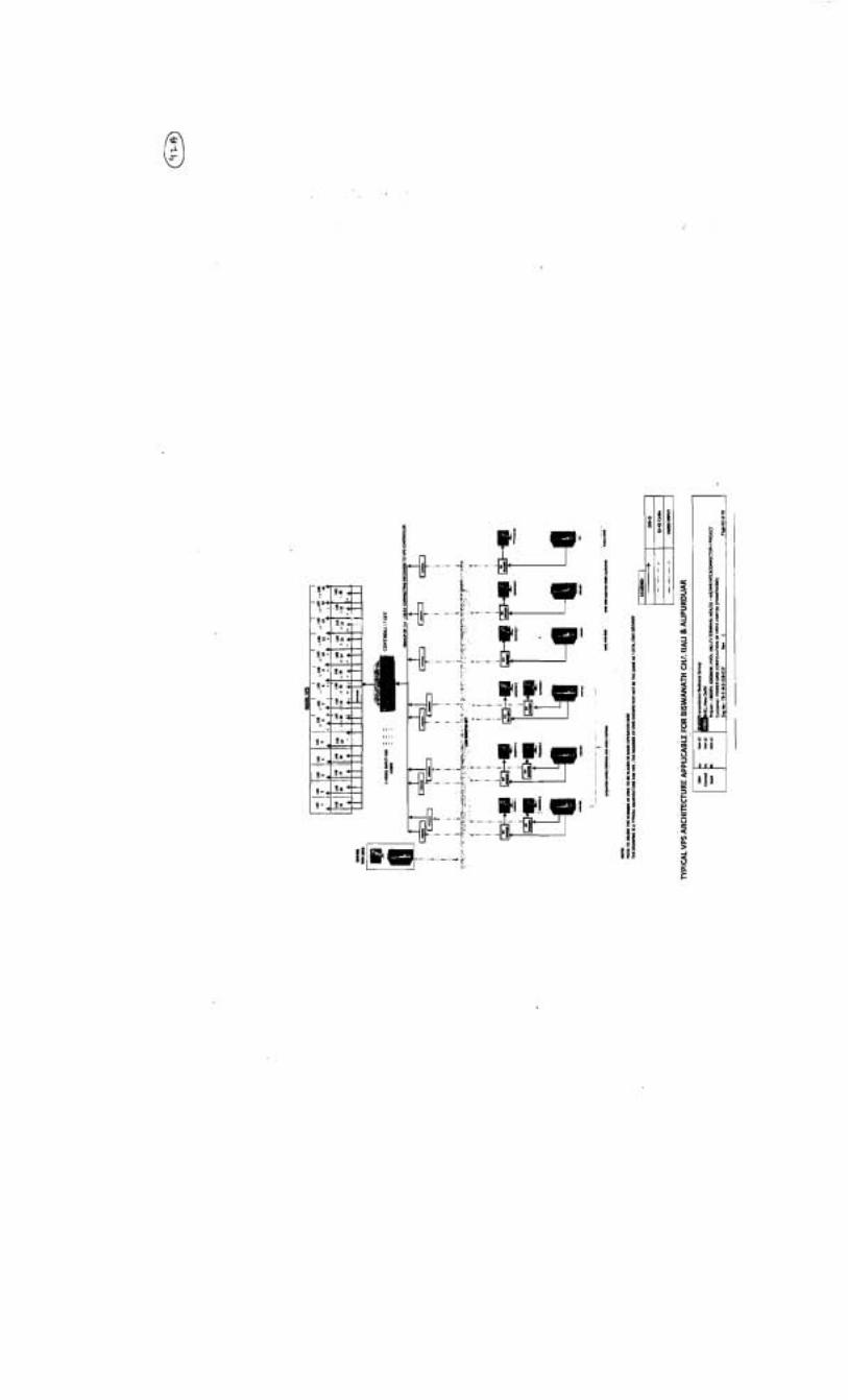
1.3.9 As per specification, the supplies shall include, but not limited to the following- 1. 67" Diagonal rear projection wall1 cube (14 x 2 configuration) 2. Encoder(s) 3. Decoder(s) 4. Server PC alongwith licensed sokKare 5. Network switch(s) 6. Controller(s) 7 . Mounting frame and pedestal 8. Distribution/ Extension Boards 9. All type of special and aux power cables and their connectors 10. Any other item required to complete the system.
Any equipment or accessory which may not have been specifically mentioned, but which is usual or is necessary for satisfactory and trouble free operation shall be within the scope of supply without any extra charge at contract stage.
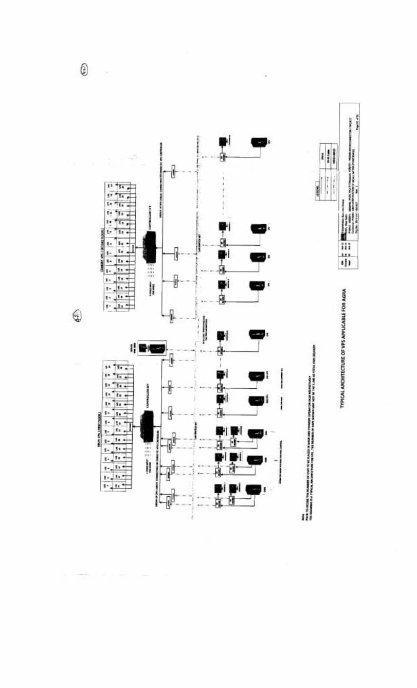
A tentative VPS architecture is attached for reference.
1.3.10 VPS supplier shall arrange the equipment, instruments, accessories, tools & tackles, distribution cables1 wires and distribution/ extension boards etc. required for the successful installation and commissioning of VPS at each station.
1.3.11 All spares shall be available at each station prior to commencement of trial operations.
- -
Page 3
*800KV, 6000MW, HVDC MULTI-TERMINAL NElUER - NRIWR INTERCONNECTOR-I PROJECT
VIDEO PROJECTION SYSTEM
Doc. No. : TB-343-558-037, Rev. 01
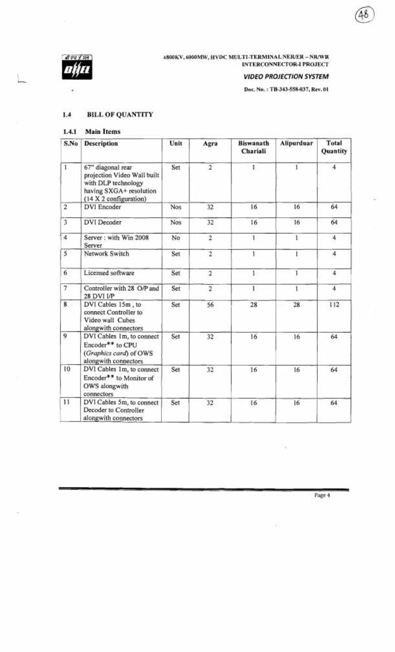
1.4 BILL OF QUANTITY
1.4.1 Main Items
Page 4
.
Alipurduar S.No Total Quantity
Unit Description
1
2
3
4
5
6
7
8
9
10
1 1
67" diagonal rear projection Video Wall built with DLP technology having SXGA+ resolution (14 X 2 configuration) DVI Encoder
DVI Decoder
Server : with Win 2008 Server Network Switch
Licensed software
Controller with 28 O/P and 28 DVI I/P DVI Cables 15m , to connect Controller to Video wall Cubes alongwith connectors DVI Cables lm, to connect Encoder* * to CPU (Graphics card) of OWS alongwith connectors DVI Cables 1 m, to connect Encoder* * to Monitor of OWS alongwith connectors DVI Cables 5m, to connect Decoder to Controller al~ngwith connectors
Set
Agra
Nos
Nos
No
Set
Set
Set
Set
Set
Set
Set
Biswanath Chariali
32
32
2
2
2
2
56
32
3 2
32
16
16
1
1
1
1
2 8
16
16
16
16
16
1
1
1
1
28
16
16
16
64
64
4
4
4
4
112
64
64
64
*800KV, 6000MW, HVDC MULTI-TERMINAL NERIER - N W R INTERCONNECTOR-1 PROJECT
Description Unit
VIDEO PROJECTION SYSTEM
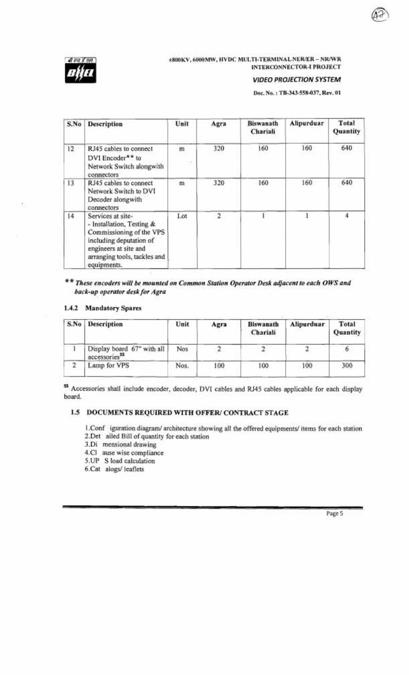
RJ45 cables to connect DVI Encoder* * to Network Switch alongwith connectors RJ45 cables to connect Network Switch to DVI Decoder alongwith connectors Services at site- - Installation, Testing & Commissioning of the VPS including deputation of engineers at site and arranging tools, tackles and equipments.
Doc. No. : TB-343-558437, Rev. 01
m
m
Lot
** These encoders will be mounted on Common Station Operator Desk adjacent to each OWS and back-up operator desk for Agra
1.4.2 Mandatory Spares
Total Quantity
Alipurduar Agra
Accessories shall include encoder, decoder, DVI cables and RJ45 cables applicable for each display board.
Biswanath Chariali
S.No
1
2
1.5 DOCUMENTS REQUIRED WITH OFFER1 CONTRACT STAGE
1 .Conf iguration diagram1 architecture showing all the offered equipmentsl items for each station 2.Det ailed Bill of quantity for each station 3 .Di mensional drawing 4.C1 ause wise compliance 5.UP S load calculation 6.Cat alogsl leaflets
Description
Display board 67" with all accessoriesSS Lamp for VPS
Alipurduar
2
100
Total Quantity
6
300
Unit
Nos
Nos.
Agra
2
100
Biswanath Chariali
2
100
*800KV, 6000MW, HVDC MULTI-TERMINAL NEWER - NR/WR INTERCONNECTOR-I PROJECT
VIDEO PROJECTION SYSTEM
Doc. No,. : TB-343-558-037, Rev. 01
7. Test certificatesftype testsf routine test plan as per relevant standard 8. Reference list of the projects where similar equipment for similar application is being used for
at least two years. 9. Installation & commissioning manuals and Operation & maintenance manuals.
1.6 INSPECTION
VPS supplier shall submit the FAT (Factory acceptance Test) and SAT (Site Acceptance Test) procedure for approval by BHELf Employer.
Page 6
*800KV, 6000MW, HVDC MULTI-TERMINAL NER/ER - NRJWR INTERCONNECTOR-I PROJECT
VIDEO PROJECTION SYSTEM
Doc. No. : TB-343-558-037, Rev. 01
SECTION -11
EQUIPMENT SPECIFICATION
2.1 This specification is intended to specify the requirements for design, engineering, manufacture, assembly, testing, supply, transport, installation and testing at site of a digital display system comprising of a state of the art Video Projection System (VPS) of high resolution with capabilities of multi-screen processing and multiple signal source switching with centralised controller.
The system shall have the following features:
The VPS supplier should quote specific Make and Model of the item being offered for VPS. Video Projection system (VPS) shall be of at least 2 ( R ) X14 ( C ) , each unit of 67" diagonal size built with DLP technology with SXGAf resolution of at least 1400X1050 pixel. Seams shall be less than 0.8mm.
a. Shall support PC Workstation, composite video, S-Video and TMDS digital RGB signal inputs.
b.Sh all support 24-bit true colour display. c. Shall have provision to connect 16 nos PCIWorkstation RGB wideband Video signals with
matrix switcher. d.Sh all have brightness of at least 600ANSI using single lamp and at least 1100 using dual lamp
and contrast ratio of minimum 1800:l.
2.3 The centralised controller shall support TCP/IP compatible single or multiple Ethernet interfaces. Back up VPS at Agra shall be similar to main VPS.
2.4 The main and back up VPS at Agra shall be at different floors (1st & 2nd floors). The similar provision for VPS, considering future upgradation of Biswanath Chariali & Alipurduar, shall be kept and shown in the relevant drawing.
2.5 Each Projection cube shall have dual lamp, with no mechanical movement during lamp switch (either of the lamp or of any other part like mirror or prism) over when one lamp fails. The average expected life shall be min 8000 hrs for each lamp. The lamps used should be variable power lamps to address the display at various required power levels.
If required, it should be possible to switch ON both the lamps simultaneously to get a brighter picture at least 1.2-1.4 times than with the single lamp. This may be required when both lamps are towards the end of their life and light of single lamp is not sufficient for projecting clear picture.
2.6 The VPS should have settings for brightness control to match the brightness of the various projection modules to get a fully uniform display wall.
2.7 The cube system should have rear access only for the maintenance purposes to avoid any misalignment of the screens in the front.
*800KV, 6000MW, HVDC MULTI-TERMINAL NERIER - NR/WR INTERCONNECTOR-I PROJECT
VIDEO PROJECTION SYSTEM
Doc. No. : TB-343-558-037, Rev. 01
2.8 It should be possible to combine individual cubes to form a large display wall by stacking more such cubes horizontally and vertically to make a big display and selecting the controller with the right optional cards without any additional costs of integration or any other mechanical costs.
2.9 The VPS supplier should have their own manufacturing facility in India for the completed final product with direct presence for after sales & support offices in India. The VPS supplier should have experience of supplying to 24x7 operations in a similar application in India.
2.10 Each cube should have diagnostic LED'S to aid in diagnosing any fault in the cubes.
2.1 1 Each VPS system of 2 (R) x 14 (C) shall be connected to a controller which will make it behave as one logical screen.
2.12 The controiler shall have at least 28 DVI inputs to be shown simultaneously
2.1 3 The controller should be integrated with real time network streaming decoder to provide mirror images of the workstations in the control room through the LAN in ReaI Time. The controller should be interfaced with the cubes with DVI outputs.
2.14 The real time network decoder should have RJ-45 as input for LAN and compatible with TCP/IP, UDP and DHCP. It should also have a decoding fiame rate of 1-30 fps adjustable. The color depth should be 24 bit with progressive scanning.
2.1 5 The decoder should offer a 4:3 aspect ratio output and should also support audio output.
2.16 The controller should be based on Windows XPNista to support 28 or more cubes.
2.17 Provision is required to be kept for back-up VPS room in the design at Biswanath Chariali & Alipurduar, so that it can be constructed later by Employer, when required.

SOOKV, 6000MW, HVDC MULTI-TERMINAL NEWER - NRIWR INTERCONNECTOR-I PROJECT
VIDEO PROlECflO N SYSTEM
Doc. No. : TB-343-558437, Rev. 01
SECTION3
GENERAL TECHNICAL REQUIREMENTS
Please refer Document TB-343-316-000 for General Technical Requirements
BHARAT HEAW ELECTRICAL. LIMITED TRANSMISSION BUSINESS ENGINEERING MANAGEMENT
1 TITLE
DOCUMENT No.
TYPE OF DOC.
~USTOMER I Powergrid Corporation of India Ltd.
TB-343-31 6-000
GENERAL TECHNICAL REQUIREMENTS- SECTION 3
- - -
+,IOOKV, 6000MW, HVDC MULTI-TERMINAL NEWER - N W R 1 P R O J E c T j INTERCONNECTOR-I PROJECT
Rev. NO.
DATE
GROUP
'TECHNICAL SPECIFICA'I'ION
LOA NO.
SIGN
02
06.04.1 1
TBEM
-
C-61901R-S056-8/NOA-II/3660 dated 21.3.2011 for Sup- plies & C-61901R-S056-8/NOA-IV/3662 dated 21.3.2011 for Services
R e v N o .
C o p i e s
Prepared
07.04.1 1
W.O. No
I I Check D a t e tered ed
07.04.1 1
8001 4
Distr ibut ion
1
Checked
A p p r o v e d
pzed
REVISION DETAILS
To
1
EM I TBMM I TBQM ( supplier
1 4
k800KV. 6000MW. HVDC MULTI-TERMINAL NEWER . N W R INTERCONNECTOR-I PROJECT
General Technical Requirements- Section 3 Doc . No . : TB-343-316-000 Rev . 02
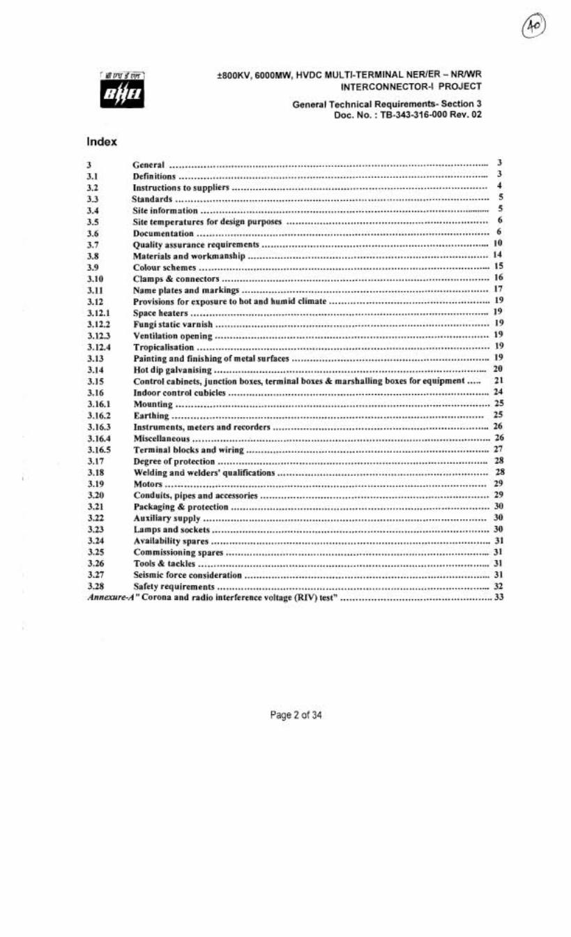
Index
3 General .................................................................................................... 3 3.1 Definitions ...................................................................................................... 3
.................................................................................... 3.2 Instructions to suppliers 4 3.3 Standards .................................................................................................. 5 3.4 Site information ................................................................................................ 5 3.5 Site temperatures for design purposes .................................................................. 6
................................................................................................ 3.6 Documentation 6 ........................................................................... 3.7 Quality assurance requirements 10
3.8 Materials and workmanship ............................................................................. 14 ................................................................................................ Colour schemes 15
........................................................................................ Clamps & connectors 16 ................................................................................. Name plates and markings 17
Provisions for exposure to hot and humid climate ..................................................... 19 .................................................................................................. Space heaters 19
.......................................................................................... Fungi static varnish 19
.......................................................................................... Ventilation opening 19 Tropicalisation ................................................................................................ 19 Painting and finishing of metal surfaces ................................................................ 19
.......................................................................................... Hot dip galvanising 20 Control cabinets. junction boxes. terminal boxes & marshalling boxes for equipment ..... 21
....................................................... ............................. Indoor control cubicles 24 Mounting .................................................................................................. 25 Earthing ...................................................................................................... 25
....................................................................... Instruments, meters and recorders 26 Miscellaneous .................................................................................................. 26 Terminal blocks and wiring .............................................................................. 27 Degree of protection ....................................................................................... 28 Welding and welders' qualifications .................................................................... 28 Motors .................................................................................................... 29 Conduits, pipes and accessories ......................................................................... 29 Packaging & protection ..................................................................................... 30 Auxiliary supply .......................................................................................... 30 Lamps and sockets ...................................................................................... 30 Availability spares ....................................................................................... 31 Commissio~ling spares .................................................................................... 31 Tools & tackles .............................................................................................. 31 Seismic force consideration ................................................................................ 31 Safety requirements ...................................................................................... 32
-A" Corona and radio interference vcltage (FUV) test" .................................................. 33
Page 2 of 34
f 800KV, 6000MW, HVDC MULTI-TERMINAL NERlER - N W R INTERCONNECTOR-I PROJECT
General Technical Requirements- Section 3 Doc. No. : TB-343-316-000 Rev. 02
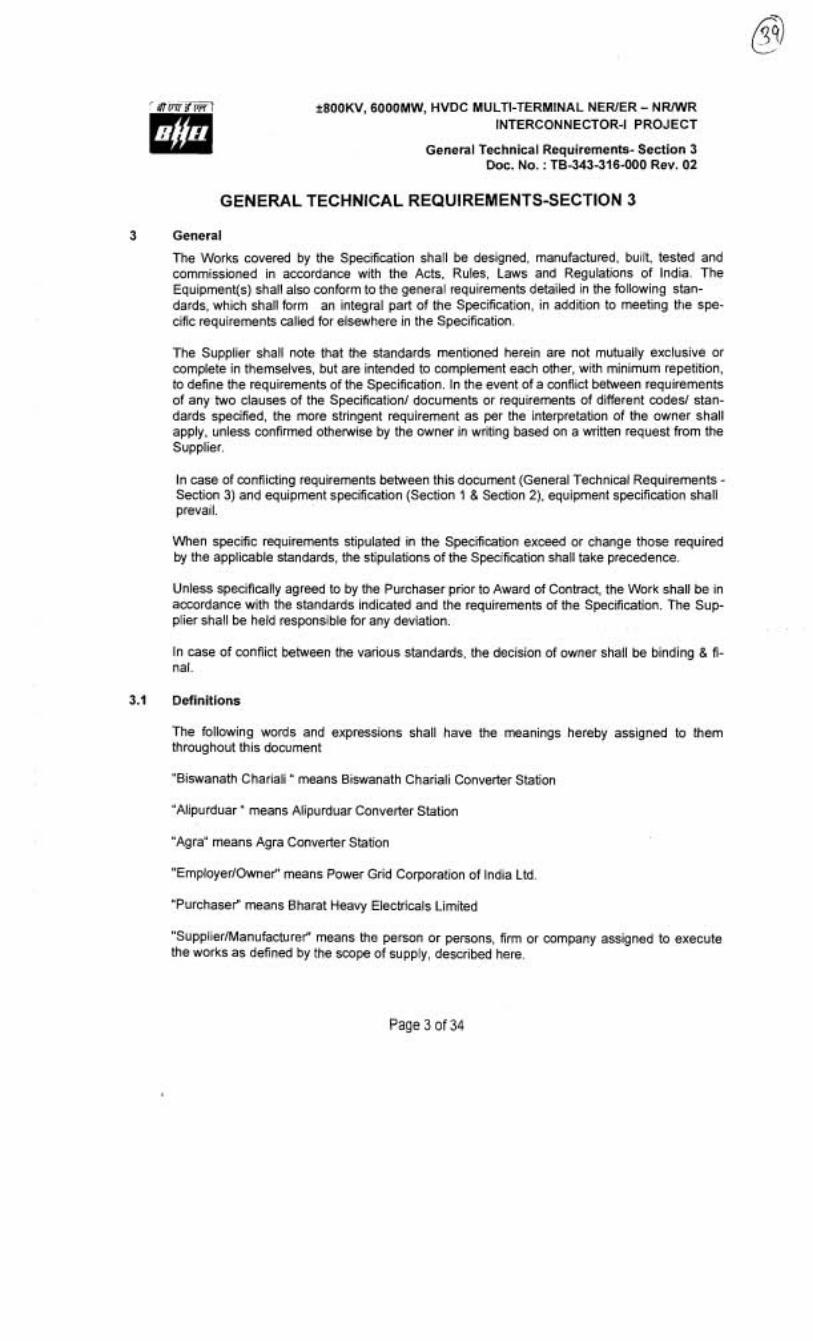
GENERAL TECHNICAL REQUIREMENTS-SEC'TION 3
3 General
The Works covered by the Specification shall be designed, manufactured, built, tested and commissioned in accordance with the Acts, Rules, Laws and Regulations of India. The Equipment(s) shall also conform to the general requirements detailed in the following stan- dards, which shall form an integral part of the Specification, in addition to meeting the spe- cific requirements called for elsewhere in the Specification.
The Supplier shall note that the standards mentioned herein are not mutually exclusive or complete in themselves, but are intended to complement each other, with minimum repetition, to define the requirements of the Specification. In the event of a conflict between requirements of any two clauses of the Specification1 documents or requirements of different codes1 stan- dards specified, the more stringent requirement as per the interpretation of the owner shall apply, unless confirmed otherwise by the owner in writing based on a written request from the Supplier.
In case of conflicting requirements between this document (General Technical Requirements - Section 3) and equipment specification (Section 1 & Section 2), equipment specification shall prevail.
When specific requirements stipulated in the Specification exceed or change those required by the applicable standards, the stipulations of the Specification shall take precedence.
Unless specifically agreed to by the Purchaser prior to Award of Contract, the Work shall be in accordance with the standards indicated and the requirements of the Specification. The Sup- plier shall be held responsible for any deviation.
In case of conflict between the various standards, the decision of owner shall be binding & fi- nal.
3.1 Definitions
The following words and expressions shall have the meanings hereby assigned to them throughout this document
"Biswanath Chariali " means Biswanath Chariali Converter Station
"Alipurduar " means Alipurduar Converter Station
"Agra" means Agra Converter Station
"EmployerlOwnet" means Power Grid Corporation of India Ltd
"Purchaser" means Bharat Heavy Electricals Limited
"SupplierlManufacturet" means the person or persons, firm or company assigned to execute the works as defined by the scope of supply, described here.
Page 3 of 34
+800KV, 6000MW, HVDC MULTI-TERMINAL NEWER - N W R INTERCONNECTOR-I PROJECT
General Technical Requirements- Section 3 Doc. No. : TB-343-316-000 Rev. 02
"Specification" refers to this document.
3.2 Instructions to Suppliers
The supplier should be approved by Power Grid. If not, it is the responsibility of the vendor to be assessed and approved by Power Grid, before placement of order by BHEL. Any cost in- volved in vendor assessment/approval must be borne by the vendor himself.
The supplier shall submit the technical requirements, data and information as per the technical data sheets provided in the appropriate clause of bid document.
Equipment furnished shall be complete in every respect with all mountings, fittings, fixtures and standard accessories normally provided with such equipment andlor needed for erection, completion and safe operation of the equipment as required by applicable codes though they may not have been specifically detailed in the Specifications unless included in the list of ex- clusions. Materials and components not specifically stated in the specification but which are necessary for commissioning and satisfactory operation of the switchyardlsubstation unless specifically excluded shall be deemed to be included in the scope of the specification and shall be supplied without any extra cost. All similar standard componentslparts of similar stan- dard equipment provided, shall be inter-changeable with one another.
The Supplier shall offer equipment whose similar equipment for similar applications have been in service for at least two years from the date of first stage bid opening (30-06-2009) and should have been type tested as per relevant standards.
The suppliers who have supplied 400 kV equipment rated for 40 kA earlier to POWERGRID, may supply 50 kA rated equipment subject to fulfilling specified requirements:
The supplier shall supply type tested (including special tests as per tech. specification) equip- ment and materials. The Employer shall accept the equipment type test reports under the fol- lowing conditions:
(i) Type test in accordance with the relevant specified standards
(ii)Type tests performed within five (5) years from the date of first stage bid opening (30-06- 2009)
(iii) The type tested equipment shall be of the same design, insulation class and rating as per the equipment offered under this contract
In the event that equipment furnished includes important modifications of, or significant depar- ture from, the designs of equipment on which type test report has been furnished or if there is evidence that the equipment does not comply with the requirements of the Specifications, the Supplier shall conduct the type test without any cost implication to the Purchaser. In the price bid, the type test charges shall be included and no separate type test charges shall be indi- cated by the supplier.
Acceptance of the type test reports shall be at the discretion of the Employer. All type tests
Page 4 of 34
+800KV, 6000MW, HVDC MULTI-TERMINAL NERlER - NRMlR INTERCONNECTOR-I PROJECT
General Technical Requirements- Section 3 Doc. No. : TB-343-316-000 Rev. 02
performed after the date of award of the Contract shall be witnessed by the Employer unless authority to proceed with the tests in his absence is received from the Employer in writing.
3.3 Standards
All equipment and materials, unless otherwise specifically required in the Specification, shall conform to latest revisions of the standards listed in the Specification, in force at the time of signing of the contract for this project.
Generally the standards listed in the specification are applicable in accordance with the spe- cific requirements of the technical section covering particular alternating current equipment or materials.
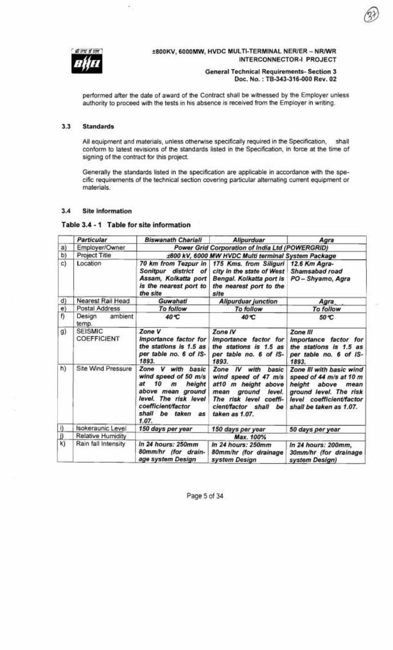
3.4 Site information
Table 3.4 - I Table for site information
Page 5 of 34
a) b) c)
d) e) 9
g)
h)
i) J) k)
Particular EmployerIOwner Project Title Location
Nearest Rail Head Postal Address Design ambient temp. SEISMIC COEFFICIENT
Site Wind Pressure
lsokeraunic Level Relative Humidity Rain fall Intensity
Biswanath Chariali I Alipurduar Agra Power Grid Corporation of India Ltd (POWERGRID)
a 0 0 kV, 6000 70 km from Tezpur in Sonitpur district of Assam, Kolkatb port is the nearest port to the site
Guwahati To follow
40 4:
Zone V Importance factor for the stations is 1.5 as per table no. 6 of IS- 1893. Zone V with basic wind speed of 50 m/s at 10 m height above mean ground level. The risk level coefficientlfactor shall be taken as 1.07. 150 days per year
M W HVDC Multi terminal 175 Kms. from Siliguri city in the state of West Bengal, Kolkaffa port is the nearest port to the site
Alipurduar junction To follow
40 4:
Zone IV Importance factor for the stations is 1.5 as per table no. 6 of IS- 1893. Zone IV with basic wind speed of 47 m/s atlO m height above mean ground level. The risk level coeffi- cientlfactor shall be taken as 1.07.
150 days per year Max. 100%
System Package 12.6 Km Agra- Shamsabad road PO - Shyamo, Agra
Aqra* . To follow
50 4:
Zone 111 Importance factor for the stations is 1.5 as per table no. 6 of IS- 1893. Zone 111 with basic wind speed of 44 m/s at 10 height above mean ground level. The risk level coefficientlfactor shall be taken as 1.07.
50 days per year
In 24 hours: 200mm, 30mm/hr (for drainage system Design)
In 24 hours: 250mm 8Omm/hr (for drain- age system Design
In 24 hours: 250mm 80mm/hr (for drainage system Design

f800KV, 6000MW, HVDC MULTI-TERMINAL NEWER - N W R INTERCONNECTOR-I PROJECT
General Technical Requirements- Section 3 Doc. No. : TB-343-316-000 Rev. 02
3.5 Site temperatures for design purposes
The Supplier shall assume the temperatures given below for the design of the works at the converter stations.
Table 3.5 - 2 Table for Site temperatures
3.6 Documentation
Description Site
Maximum dry bulb one hour average Maximum dry bulb 24 hour average Annual mean dry bulb temperature Minimum dry bulb one hour average Maximum wet bulb one hour avsrage Dry bulb temperature for low ambient condition Wet bulb temperature for low ambient condition
All technical description, specifications, literature, correspondence, prints, drawings, instruction manuals, test reports( both factory and site), progress photographs, booklets, schedules and all sup- plementary data or documents furnished in compliance with the requirements of the Contract, shall become the property of the Purchaserlowner and the costs shall be considered as in- cluded in the Contract price.
The Supplier shall be responsible for any time delay, misinterpretation, error and conflict during design, manufacturing, testing and erection of the Works resulting from non-compliance with the requirements of this Specification. . _., G. .
The Purchaserlowner shall have the right to make copies of any documents, data, reports, infor- mation etc. supplied by the Supplier in connection with the Works. The Purchaser1 owner shall not impart the information of these documents to any other manufacturer or competitor but he shall be free to use these for preparation of technical papers, reports etc.
C Agra
50 40 30 0 33 33 23
Temperature in deg
The Supplier shall submit consolidated list of all symbols used in any drawing, data and informa- tion under three separate headings namely Civil, Mechanical & Electrical. If symbols other than IS or IEC are used, the Supplier shall submit consolidated list of these symbols and their signifi- cance under a separate section.
Biswanath Chariali
40 40 30
. O 33 33 23
The Supplier is not required to supply detailed drawings whose purpose is manufacture only butin case such information is specifically asked for by the Purchaserlowner during evaluation of Bid, finalization of Contract, design review by Purchaserlowner his appointed Consultant or during execution of the Contract, the Supplier shall comply with the same.
Alipurduar
40 40 30 0 33 33 23
All drawings, documents manual etc. as specified in this section shall have to be provided sepa- rately for each station.
All documentation shall be in English language.
Requirements for submission of documents, information and data by the supplier
Page 6 of 34
f 800KV, 6000MW, HVDC MULTI-TERMINAL NEWER - N W R INTERCONNECTOR-I PROJECT
General Technical Requirements- Section 3 Doc. No. : TB-343-316-000 Rev. 02
General
The Supplier shall submit to the OwnerIPurchaser all documents in accordance with an approved schedule of submissions and shall submit any further information (in the form of drawings, docu- ments, manuals, literature, reports etc.) when asked by the OwnerlPurchaser while comment- inglapproving any drawingsldocuments etc. All applicable documents shall be provided for each converterlrepeater station separately.
The documents which are subject to the approval of the OwnerlPurchaser shall be identified by the Supplier with the stamp "FOR APPROVAL". All other documents shall be submitted to the OwnerIPurchaser for information and shall be identified by the Supplier with the stamp "FOR INFORMATION".
The sequence of submission of the documents shall be subject to the approval of the Employer. The sequence of submissions of all documents shall be such that the necessary information is available to enable the Employer to approve or comment the document.
The Supplier shall supply 5 hard copies of all drawings and documents. The final documentation for the project shall be supplied in nine sets of hard copies (three to each site) and nine sets of CDs to the Purchaser.
The entire plant documentation shall include all construction drawings, equipment specifications, designlstudy reports, O&M documents, factory test reports, etc. All the finallas built drawings shall be submitted in CAD format along with the complete final documentation.
In case a "SUBSEQUENT" revision of any document is made due to any reason whatsoever, a revi- sion of the same, highlighting the changes shall be resubmitted for the Employer's specific approval1 information. - I .I Documents for approval
Approved documents shall be considered as the working documents. However the Specification and connected documents shall prevail over these documents in case a decision is required on interpre- tation.
Documents for information
The Supplier shall not delay the Works pending the receipt by the supplier of the comments on documents submitted to the OwnerIPurchaser for information. However, the OwnerlPurchaser shall have the right to comment on all the documents submitted by the Supplier, when, in the opinion of the OwnerIPurchaser the document does not comply with the Contract or otherwise. The Supplier shall satisfactorily demonstrate that the information contained in the aforesaid document does meet the requirements of the Contract or revise the document in order that the information shall comply with the requirements of the Contract.
Drawings and data
General
The Supplier shall submit to the Owner/Purchaser all assembly and detail drawings of equipment,
Page 7 of 34
+800KV, 6000MW, HVDC MULTI-TERMINAL NERlER - N W R INTERCONNECTOR-I PROJECT
General Technical Requirements- Section 3 Doc. No. : TB-343-316-000 Rev. 02
station design, civil work, building, controls, protection, etc., as well as the corresponding computa- tion where necessary in order to establish to the satisfaction of the OwnerIPurchaser the Supplier's compliance with the requirements of the Contract.
Drawings, as set forth below shall be submitted to the OwnerIPurchaser and shall be completewith all information necessary for complete interpretation of the drawings by the Owner1 Purchaser. All drawings shall show the materials, dimensions, finish, fits, clearances, tolerances, bolting and such other information as is necessary to demonstrate to the Owner1 Purchaser that all items covered by the drawings are in compliance with the requirements of the Contract.
Drawings may consist of several sheets as required in order to provide for the degree of detail re- quired by the Employer, so that he may clearly understand such drawings.
Not later than 90 (ninety) days after completion of successful trial operation of the HVDC station, the Supplier shall supp!y copies of the last revision of all drawings produced for this project, stamped as "AS BUILT'.
The Supplier shall provide separate sets of drawings for each control cubicle. Typical drawings for similar cubicles shall fiat be accepted. If there are several cubicles per system, then one common bill of material and one system schematic diagram may be provided. Such system schematic dia- gram shall show the control scheme for the particular system in its entirety and shall be laid out on the minimum number of drawings sheets consistent with clarity and legibility.
The OwnerIPurchaser shall not accept typical drawings for control, protection and three-phase sche- matics, power circuits and single line diagrams. The Supplier shall supply complete set of such drawings for each system, even when drawings are duplicates.
. . .*
Inspections plans and documentation
The Supplier shall submit in required number copies for the Owner'sIPurchaser's approval an in- spection plan (quality plan) describing the inspection system indicating the inspections to be carried out and their sequence in the manufacturing stages.
The inspection plan shall be such that it can be related to the manufacturing program. The plan shall also include a description of the inspection methods employed with reference to the Supplier's writ- ten inspection procedures.
Separate inspection plans describing the inspection systems for equipment supplied by each sub-supplier, in the same form as that of the Supplier, shall be submitted for the approval of the OwnerIPurchaser.
In addition to the inspection plans referred to above, the Supplier shall submit complete and satis- factory evidence of possessing a working scheme assuring the control of all critical activities perti- nent to the assurance of quality, and objective evidence (by means of quality manuals and appropri- ate forms, etc.) of this capability to employ and maintain quality control to meet the required quality level of the manufacture and construction of the Works.
Supplier's Quality Control Program in the context of this Clause means the implementation of a qual- ity assurance program by means of which full conformance of material and workmanship to best
Page 8 of 34
2800KV, 6000MW, HVDC MULTI-TERMINAL NEWER - N W R INTERCONNECTOR-I PROJECT
General Technical Requirements- Section 3 Doc. No. : TB-343-316-000 Rev. 02
quality standards can be achieved effectively and economically by the Supplier's control and surveil- lance of all essential inspection operations, and periodic verification of the results of the manufacture of equipment and the assembly, erection and installation of equipment at the sites.
Required number of copies of all test reports, including those supplied by Sub-Suppliers, and shall be submitted to the OwnerlPurchaser for approval. The Supplier shall include in the report all addi- tional data required by the OwnerIPurchaser to permit a clear understanding of the reports.
All test reports shall be certified and shall contain the signature of the Inspector as having witnessed the test, unless such witnessing has been specifically waived by the Owner1 Purchaser. A certified test report shall be issued for each test.
lnstruction manuals and operating manuals
The Supplier shall provide lnstruction & Maintenance Manuals for each part of the Fiant and Equip- ment included in the Works and Operating Manuals for each Station.
The lnstruction Manuals and Operating Manuals shall be arranged in an organized library ade- quately cross referenced to facilitate issuing clauses of the manuals as required by the work i.e. erection instructions shall be required before operating & maintenance instructions.
All Manuals provided by the Supplier shall be fully detailed and specifically prepared for the Works and equipment provided. General manuals not specifically required for the work shall not be accept- able.
The instruction manuals shall at least contain:
a) A general description of all components b) Storage instructions c) Erection instructions d) Pre-commissioning Instruction : e) Material and part list. f) Design clearances and settings g) Complete sets of drawings as finally issued h) Operating Instructions: i) Routine and Preventive Maintenance instructions with material requirement for each site j) Preventive Maintenance Schedule. k) Replacement instruction for all equipment
The operation manuals shall at least contain: a) Operator oriented functional descriptions of the equipment. b) Operator oriented description of the protection and control systems c) Description of the equipment auxiliary systems d) Fault finding and diagnostic tools e) User software interface tools for modification/augmentation etc.
Notes:
The supplier may please note that all resubmissions must incorporate all comments given in the ear-
Page 9 of 34
f800KV, 6000MW, HVDC MULTI-TERMINAL NEWER - N W R INTERCONNECTOR-I PROJECT
General Technical Requirements- Section 3 Doc. No. : TB-343-316-000 Rev. 02
lier submission by the OwnerIPurchaser or adequate justification for not incorporating the same must be submitted failing which the submission of documents is likely to be returned.
If after the commissioning and initial operation of the substation, the instruction manuals require any modifications1 additionslchanges, the same shall be incorporated and the updated final instruction manuals shall be submitted by the Supplier to the OwnerlPurchaser.
The Supplier shall furnish to the OwnerIPilrchaser, catalogues of spare parts also.
3.7 Quality assurance requirements
Quality assurance programme
To ensure that the equipment and services under the scope of Contract, whether manufactured or performed at the Supplier's Works or at his Sub-supplier's premises or at the Purchaser's site or at any other place of Work, are in accordance with the specifications, the Supplier shall adopt a suit- able quality assurance programme to control such activities at all points, as necessary. Such pro- granme shall be outlined by the Supplier and shall be submitted by the supplier after the award of contract and finally accepted by the owner after discussions prior to commencement of manufactur- ing.
A quality assurance programme of the supplier shall generally cover the following:
Supplier's organisation structure for the management and implementation of the proposed quality assurance programme; Design and Documentation control system; Qualification data of Supplier's key personnel; The procedure for purchases of materials, parts components and selection of sub-supplier's services including vendor analysis, source inspection, incoming raw material inspection, verifi- cation of material purchased etc. System for shop manufacturing and site erection controls including process controls and fabri- cation and assembly control; Control of non-conforming items and system for corrective actions; Inspection and test procedure both for manufacture and field activities; Control of calibration and testing of measuring and testing equipment. System for quality audits; System for indication and appraisal of inspection status System for authorising release of manufactured product to the Purchaser System for maintenance of records; Furnishing of quality plans (QP)/inspection and test plan (ITP) for manufacturing and field ac- tivities detailing out the specific quality control procedure adopted for controlling the quality characteristics relevant to each item of equipmentlcomponent.
General requirements - Quality assurance
1. All services, materials, components and equipment covered under this specification shall be en- gineered, designed, procured, manufactured, erected, commissioned and tested at all the stgges, as per a comprehensive Quality Assurance Programme. It is the Supplier's responsibility to draw up and implement agreed programme for system as a whole as well as for individual equipment.
Page 10 of 34
-1800KV, 6000MW, HVDC MUCI-I-TERMINAL NEWER - N W R INTERCONNECTOR-I PROJECT
General Technical Requirements- Section 3 Doc. No. : TB-343-316-000 Rev. 02
The detailed Quality Plans for manufacturing and field activities shall be drawn up by the Supplier and shall be submitted to the Employer for approval.
The Supplier shall furnish with his bid a list of approved suppliers for the information of the Em- ployer.
Engineering and design quality Plan shall detail out the studies, overall detail design documenta- tion and communicating, defining interfaces and controlling changes. To achieve quality, reliability and schedule objectives that project shall be designed so that it meets performance requirements. Manufacturing Quality Plan shall detail out for all the components and equipment, various testslinspection, to be carried out as per the requirements of this Specification and standards mentioned therein and quality practices and procedures followed by Supplier's Quality Control Organisation, the relevant reference documents and standards, acceptance norms, inspection documents etc., during all stages of materials procurement, manufacture, assembly, and final testinglperformance testing.
3. Field Quality Plan shall detail out for all the equipment, the quality practices and procedures etc. to be followed by the Supplier's site Quality Control Organisation, during various stages of site ac- tivities from receipt of materialslequipment at site onwards.
4. The Supplier shall also furnish copies of the reference documentslplant standards1 acceptance normsltests and inspection procedure etc., as referred in Quality Plans along with respective Quality Plan. These Quality Plans and reference documentslstandards etc. shall be subject to Employer's approval without which manufacture shall not proceed. In these approved QPs, the Employer shall identify customer inspection points (CIP), tesffchecks which shall be carried out in presence of the Employer's Engineer or his authorised representative and beyond which the work shall not proceed without consent of Employer or his authorised representative in writing. All de- viations to specification, approved quality plans and applicable standards must be documented and referred to the Employer for approval and disposition.
5. No material shal! be dispatched ,from the manufacturer's works before the same is accepted subsequent to pre-dispatch final inspection including verification of records of all p'revious testslinspections by Employer's Engineer and 1 or his authorised representative, and duly author- ised for dispatch issuance of Material Inspection Clearance Certificate (MICC). Before making re- quest for issuance of IVIICC, the Supplier shall ensure that approval of type tests, data sheets, drawing etc. had already been obtained from Employer. All materials used or supplied shall be accompanied by valid materials certificates and tests and inspection reports. These certificates and reports shall indicate the sheet numbers or other such acceptable identification numbers of the material. The material certified shall also have the identification details stamped on it.
6. All welding and brazing shall be carried out as per procedure drawn and qualified in accordance with requirements of ASME section - IWBS-4870 or other International equivalent standard ac- ceptable to the Employer.
7. All the (sub)-Vendors proposed by the Supplier for procurement of bought out item list of which shall be drawn up by the Supplier and finalised with the Employer shall be subject to the Em- ployer's approval. Quality Plans of the successful vendors shall be discussed, finalised and ap- proved by the Employer and shall form part of the purchase order between the Supplier and the Vendor.
Page 11 of 34

2800KV, 6000MW, HVDC MULTI-TERMINAL NEWER - N W R INTERCONNECTOR-I PROJECT
General Technical Requirements- Section 3 Doc. No. : TB-343-316-000 Rev. 02
8. The Employer reserves the right to carry out quality audit and qualify surveillance of the systems and procedures of the Supplier's of their sub-Supplier's (sub-vendor's) quality management and control activities. The Supplier shall provide all necessary assistance to enable the Employer carry out such audit and surveillance.
9. As a part of quality assurance of engineering and design, the technical review meetings (TRMs) shall be conducted between the Employer andlor his consultants/representative and the Supplier andlor his subSupplier(s). The duration and cycle of such TRMs shall be as frequent and regular as required to meet the time schedules. The meetings shali be held at either at the Employer's office and/or at the ofke/manufacturing place of the Supplierlsub-Supplier or at any other place as agreed mutually.
10. The Supplier shall agree upon a schedule of submissions of documents concerning the Quality Assurance Program within two months of the effective date of the Contract. This schedule shall indicate the list of mutually agreed itemslequipment for which quality Plans shall be submit- ted by the Supplier and the last dates for the submissions. It shall be ensured by the Supplier that the submissions are so programmed that all relevant approvals are obtained from the Employer for these documents in a timely manner before the material induction and commencement of the manufacture for any equipment.
11. The documents that shall be submitted by the Supplier to the Employer for review and approval as per the agreed schedule include:
a) QA Manuals b) Quality Plans (Inspection & Test Plans) for all equipmenffmaterials manufactured in the Sup-
plier's works andlor in the sub-supplier's works c) Purchase Specifications for equipment procured from sub- Suppliers. d) Supplier's assessment reports of his sub-suppliers e) Field Quality Plans for all activities at site 9 Reference documents referred to in Quality Plan. g) Erection, commissioning, operation and maintenance manuals
12. QA Document Package
The Supp!ier shall submit the following Quality Assurance Documents to the Employer. These docu- ments shall be as per the approved Quality Plans for the concerned equipment. The documents shall include, but not limited to, the following:
a) Routine test reports & Acceptance test reports b) Type test reports c) Quality records etc. corresponding to items identified Quality Plan d) Inspection reports for Customer inspection points e) Reports on repairlmodification carried out to make the itemlequipment acceptable. 9 Non-destructive examination result reports including radiography interpretation reports, wher- M
ever applicable.
The above documents are required to be submitted in required number of copies within three weeks after dispatch of equipment.
Page 12 of 34

f800KV, 6000MW, HVDC MULTI-TERMINAL NEWER - N W R INTERCONNECTOR-I PROJECT
General Technical Requirements- Section 3 Doc. No. : TB-343-316-000 Rev. 02
lnspection and testing
1. In order to verify that all the manufacturing of equipment by the Supplier as well as materials & equipment being procured and provided by the Supplier are in complete conformance with the re- quirement of thecontract, the Employer andlor his duly authorized representative shall have ac- cess to the Supplier's premises or works at all reasonable times to inspect and examine the material, equipment and workman ship during its manufacture or installation. In addition to carry- ing out inspection the Employer andlor his authorized representativelConsuItant all carry out quality audit on the Supplier's Quality Assurance System and conduct quality surveillance to check conformance to quality procedurelpractice in general. The Supplier shall provide neces- sary facilities to carry out all the above activities at their works and the works of the sub- Suppli- ers.
2. The Supplier shall provide a detailed inspection schedule for those inspection stages identified as CIP and shall furnish updated schedules once every two months.
3. The Supplier shall give the Employerllnspector six(6) weeks written notice, by telex or by letter, of the tentative date any materiallequipmeni shall be ready for witness points, corresponding to Customer inspection points (CIP), when the Employerllnspector is based in India. Final confirma- tion shall be given at least 15 days in advance. The Employerllnspector, unless witnessing of the tests is waived, shall attend such tests, failing which the Supplier may proceed with the test which shall be deemed to have been made in the Inspector's presence. The Supplier shall forthwith for- ward to the Employer copies of duly certified test reports. Test reports of all tests corresponding to CIP performed in the supply shall be reviewed and approved, subject to satisfactory conduc- tion and successful passing of the test, by the Employer or his authorised representative (even if the witnessing of the test was waived).
. . 4. The Employer or his authorized representative shall, within fifteen (15) days from receipt of such reports, give notice in writing to the Supplier of any objection to any aspect of the test reports or any or all equipment and workmanship which in his opinion is not in conformance with the Con- tract. The Employer or his authorized representative shall advise his reasons for objections on completion and review of the activity. The Supplier shall give due consideration to such objec- t ion(~) and shall either make the modifications that may be necessary to overcome the said ob- jection(~) or shall confirm in writing giving reasons therein that no modifications are necessary to comply with the Contract. However, the Supplier may proceed with the worksldispatch even be- fore the receipt of written objection(s), if any, at his own cost & risk.
5. Whenever the Employer's inspection engineer undertakes the inspection, at a particular stage identified as Customer inspection point (CIP) in the Quality Plan, the acceptance of test re- portsltest results and the MlCC where applicable shall be given immediately after the test if the results, including those for previous points identified as per clause 9.6 are found to be in con- formity with the Contract. In case of any deviations, the Employerllnspector at his discretion may refer the matter to the Employer's main office, together with the manufacturer's comments, who in turn shall communicate his final decision regarding the acceptance or otherwise to the Supplier within fifteen (15) days of the receipt of such test reportslresults. In case the presence of the Ernployerllnspector is waived, the acceptance of test results and issuance by the Employer of Material Inspection Clearance certificate wherever applicable, shall be given within fifteen (1 5) days after receipt of test reportslresults for the CIP as well as for previous CIP's identified in the approved Quality Plan, provided such test reportsltest results are found to be in order. The Em-
Page 13 of 34
+800KV, 6000MW, HVDC MULTI-TERMINAL NERlER - NRWR INTERCONNECTOR-I PROJECT
General Technical Requirements- Section 3 Doc. No. : TB-343-316-000 Rev. 02
ployerllnspector shall at his discretion and based on the outcome of any inspection and the re- quirements of the contract, have the right to 'accept', 'accept as noted' or 'reject' any equip- mentlmaterial. The reasonslcomments in case of each ruling shall be communicated to the Sup- plier in writing.
6. In all cases where the contract provides for tests, whether at the premises of works of the Sup- plier or of any sub-supplier, the Supplier, except where otherwise specified, shall provide free of charge such items as labour, materials, electricity, fuel, water, apparatus and instruments as required to fulfil the requirements of the approved Quality Plan.
7. The inspection by Employerllnspector or waver of the presence of the Employerllnspector, issue of CIP clearance certificate and issue of Material Inspection clearance certificate (MICC) thereon shall in no way limit the liabilities and responsibilities of the Supplier in respect of the agreed qual- ity plans forming part of the contract. The Employer shall not be found to accept the mate- riallequipment if on further testing it is found to be not in compliance with the requirements of the contract. The Supplier shall include in all orders to his sub-Suppliers, the requirements for any equipment, being supplied by the sub- Supplier for incorporation in his equipment to be subjected to inspection and testing by the Employer or is authorised representative. Copies of such orders or purchase specifications, blanked for prices, shall be forwarded to the Employer.
8. The costs of all tests specified in the Contract together with the same for all tests facilities, test samples and such like shall be to the Supplier's account.
9. The Employerllnspector shall have complete, authority to reject, on behalf of the Employer, any material, equipment or parts thereof considered unsatisfactory and not in accordance with the Contract. Accept, accept as noted or reject materials, equipment or any components thereof shall not relieve the Supplier of any of his obligations under the Supplier, nor impose any liability whatsoever on the Employer.
10. The Employer shall have the right to have Inspectors on the Sites, on a regular basis or from time to time as required at his sole discretion to monitor the quality and the progress of the work. Generally the site inspection shall be as per the approved Field Quality Plans (FQPs) and the In- stallation & Operation Manual(s). All quality related documents and test results shall be a part of plant documentation.
3.8 Materials and workmanship
Where the specification does not contain references to workmanship, it is understood that the equip- ment shall be new, of the best quality and in accordance with the purpose for which they are in- tended.
In case where the equipment, materials or components are indicated in the specification as "similar" to any special standard, the owner shall decide upon the question of similarity. When required by the specification or when required by the Purchaser & owner the Supplier shall submit for approval, all the information concerning the materials or components to be used in manufacture. Machinery, equipment, materials and components supplied, installed or used without such approval shall rlin the risk of subsequent rejection, it being understood that the cost as well as the time delay associ- ated with the rejection shall be borne by the Supplier.
Page 14 of 34
f800KV, 6000MW, HVDC MULTI-TERMINAL NEWER - N W R INTERCONNECTOR-I PROJECT
General Technical Requirements- Section 3 Doc. No. : TB-343-316-000 Rev. 02
The design of the Works shall be such that installation, future expansions, replacements and gen- eral maintenance may be undertaken with a minimum of time and expenses. Each component shall be designed to be consistent with its duty and suitable factors of safety shall be used throughout the design.
All joints and fastenings shall be devised, constructed and documented so that the component parts shall be accurately positioned to fulfil their required function. In general, screw threads shall be standard metric threads. The use of other thread forms will only be permitted when prior approval has been obtained from the owner.
Whenever possible, all similar parts of the works shall be made to gauge and shall also be made in- terchangeable with similar parts. All spare parts shall also be made interchangeable and shall be made of the same materials and workmanship as the corresponding parts of the equipment supplied under the specification. All the equipment of the same type and rating shall be physically and electri- cally interchangeable.
All materials and equipment shall be installed in strict accordance with the manufacturer's recom- mendation(~). All factory assembled rotating machinery shall be checked for alignment and adjust- ments made as necessary. The spare equipment(s) shall be installed at designated locations and tested for healthiness.
The Supplier shall apply oil and grease of the proper specification as is necessary for the installation of the equipment. Lubricants used for installation purposes shall be drained out and the system flushed through where necessary in readiness for applying the lubricant required for operation. The Supplier shall apply all operational lubricants to the equipment installed by him. All insulating oil, lu- bricating material, grease and other consumables used in the Works1 Equipment shall be purchased in India unless the Supplier has any special requirement for the specific application for a type of oil or grease not available in India. If such is the case he shall declare in the proposal where such oil or grease or other consumables is available. In any case he shall identify equivalent'lndian makes and inform the Purchaser & owner of the name of at least two Indian suppliers before hand- ing over of the Works to the Purchaser. All consumables required upto operational acceptance shall be the part of supply scope of the Supplier.
The supplier shall perform all tests and inspection necessary to ensure that the material and work- manship conform to the approved design drawings and that such tests are adequate to demon- strate that the equipment shall comply with the requirements of the Specification & relevant stan- dards.The supplier shall test the component parts at his plant or his Sub- supplier's plant, prior to packaging and shipping, to determine that the performance requirements have been met. All testing shall be in accordance with the Standards related to the piece of work.
3.9 Colour schemes
The Supplier shall propose a colour scheme for the equipment for the approval of the Employer. The decision of the Employer shall be final. However, the finishing colour shall be RAL 7035 for indoor panels and RAL 7032 for outdoor panels. The scheme shall include:
- Finishing colour of Indoor equipment - Finishing colour of Outdoor equipment - Finishing colour of various auxiliary system equipment including piping - Finishing colour of various building items.
Page 15 of 34
k800KV1 6000MW1 HVDC MULTI-TERMINAL NEWER - N W R INTERCONNECTOR-I PROJECT
General Technical Requirements- Section 3 Doc. No. : TB-343-316-000 Rev. 02
- Finishing colour of all cubicles.
All steel structures, plates etc shall be painted with non-corrosive paint on a suitable primer. The galvanised structures in the switchyard shall not be painted. However galvanised structures in other areas may require painting for aesthetic reasons.
3.10 Clamps & connectors
i) All power clamps and connectors shall conform to IS: 5561, and/or IEC standard and shall be made of materials listed below:
a) For connecting ACSR conduc- I lors
Aluminium alloy casting, conforming to designa- tior, A6 of IS: 617 and shall be tested for all tests as per IS:617
b)
c)
ii) Equipment shall be supplied with the necessary terminals and connectors, as required by the ul- . *
h a t e design for the particular installation. The conductor terminations of equipment shall be ei- ther expansion, sliding or rigid type. The requirements regarding external corona and RIV as specified for any equipment shall include its terminal fittings and the equipment shall be factory tested with the connectors in position. In case ihe connector is not available then equivalent connector inay be used. If corona rings are required to meet these requirements they shall be considered as part of that equipment and included in the scope of Work.
d).l
d).2
iii) Where copper to aluminium connections are required, bi-metallic clamps shall be used, which have been properly designed to ensure that any deterioration of the connection is kept to a minimum and restricted to parts which are not current t shall be furnished to the Employer.
For connecting equipment ter- minals made of copper with ACSR conductors
For connecting G.I. Shield wire
iv) Low voltage connectors, grounding connectors and accessories for grounding all equipment as specified are also included in the scope of Work.
Bimetallic connectors made from aluminium alloy casting, conforming to designation A6 of IS 617 with 2 mm thick Bimetallic liner and shall be tested as per IS: 617. Galvanised mild steel
Bolts, nuts & Plain washers.
Spring washers for items 'a' to 'c'
v) No current carrying part of any clamp shall be less than 10 mm thick. All ferrous parts shall be hot dip galvanised. Copper alloy liner of minimum 2mm thickness shall be cast integral with aluminium body for Bi-metallic clamps. When copper alloy is not cast integral with aluminium body, a bimetallic washer or strip shall be used to meet the functional requirement.
Electro galvanized for sizes below M12, for others hot dip galvanised Electro-galvanised mild steel suitable for at least service condition-3 as per IS: 1573
vi) All casting shall be free from blow holes, surface blisters, cracks and cavities. All sparp edges and corners shall be blurred and rounded off.
Page 16 of 34
+800KV, 6000MW, HVDC MULTI-TERMINAL NEWER - N W R INTE RCONNECTOR-I PROJECT
General Technical Requirements- Section 3 Doc. No. : TB-343-316-000 Rev. 02
vii) Flexible connectors, braids or laminated straps made for the terminal clamps for bus posts shall be suitable for both expansion or through (fixedlsliding) type connection of IPS Aluminium tube as required. In both the cases the clamp height (top of the mounting pad to centre line of the tube) should be same.
viii) Clamp shall be designed to carry the same current as the conductor and the temperature rise shall be equal or less than that of the conductor at the specified ambient temperature. The rated current for which the clamplconnector is designed with respect to the specified reference ambi- ent temperature, shall also be indelibly marked on each component of the clamp/connector, ex- cept on the hardware.
ix) All current carrying parts shall be designed and manufactured to have minimum contact resis- tance.
x) TESTS
The following is the list of type tests. a) Temperature rise test (maximum temperature rise allowed is 35deg C over 50 deg C ambi- ent) b) Short time current test c) Dry corona and RIV test as per annexure-A d) Resistance test and tensile test
3.11 Name Plates and Markings
All equipment mounted on front and rear side as well as equipment mounted inside the panels . , . shall be provided with individual nameplates with equipment designati~.n wgraved. Also on the top
of each panel on front as well as rear side, large and bold nameplates shall be provided for circuit1 feeder designation.
All front mounted equipment shall also be provided at the rear with individual name plates engraved with tag numbers corresponding to the one shown in the panel internal wiring to facilitate easy trac- ing of the wiring.
All relays and other devices shall be clearly marked with manufacturer's name, manufacturer's type, serial number and electrical rating data.
Name Plates shall be made of non-rusting metal or 3-ply lamicoid. Name plates shall be black with white engraving lettering.
All the panels shall be provided with nameplate mounted inside the panel. Stainless steel name- plates shall be installed on all apparatus and on all major equipment components. For indoor cubicles, nameplates made of aluminium shall also be acceptable. Name plates shall be white with black engraved lettering and shall carry all the applicable information specified in the applicable items of the Standards, together with any other relevant information which may be required. For groups of smaller items for which this is not possible e.g. switch bays etc. a common name- plate with the title and special instructions on it shall be provided. No scratching, corrections or changes shall be allowed on nameplates. Main equipments like converter transformer, CBs, Reac-
Page 17 of 34

f800KV, 6000MW, HVDC MULTI-TERMINAL NEWER - N W R INTERCONNECTOR-I PROJECT
General Technical Requirements- Section 3 Doc. No. : TB-343-316-000 Rev. 02
tor, Filter gates etc shall have nameplates in Hindi also.
All equipment mounted on front and rear sides as well as equipment mounted inside the panels shall be provided with individual name plates with equipment designation engraved. Also on the top of each panel on front as well as rear sides large name plates with bold size lettering shall be provided for circuit I feeder I cubicle I box designation.
All front mounted equipment shall also be provided at the rear with individual name plates engraved with tag numbers corresponding to the one shown in the panel internal wiring to facilitate tracing of the wiring. The nameplates shall be mounted directly by the side of the respective equipment and shall not be hidden by the equipment wiring.
The nameplate inscription and size of nameplates and letters shall be submitted to the Employer for approval.
The nameplates of the apparatus shall include, at least, the information listed below, together with any othei- relevant information specified in the applicable standards:
a) A concise descriptive title of the equipment
b) Rating and circuit diagram reference numbers
c) Manufacturer's name, trade-mark, model type, serial number d) Instruction book number e) Year of manufacture
9 Total weight (for capacitor racks indicate weight, for capacitors indicate quantity of liquid)
g). Special instructions, if any, about storage, transportation, handling etc.
Each measuring instrument and meter shall be prominently marked with the quantity measured e.g. kV, A, MW etc. All relays and other devices shall be clearly marked with manufacturer's name, manufacturer's type, serial number and electrical rating data.
Danger plates and plates for phase colours shall be provided as per requirement. The Supplier shall devise a system to designate equipment and sub-systems. The nameplates1 labels displaying these designations shall be installed at appropriate locations. Wherever motion1 flow of fluids are in- volved, plates1 marks showing direction of motion1 flow shall also be provided.
Each main and auxiliary item of substation is to have permanently attached to it in a conspicuous position a rating plate of non-corrosive material upon which is to be engraved manufacturer's name, year of manufacture, equipment name, type or serial number together with details of the loading conditions under which the item of substation in question has been designed to operate, and such diagram plates as may be required by the Purchaser. The rating plate of each equipment shall be according to IEC requirement.
All such nameplates, instruction plates, rating plates of transformers, reactors, CB, CT, CVT, SA, Isolators, C & R panels and PLCC equipments shall be bilingual with Hindi inscription first followed by English. Alternatively two separate plates one with Hindi and the other with English inscriptions may be provided.
Page 18 of 34

f800KV, 6000MW, HVDC MULTI-TERMINAL NEWER - N W R INTERCONNECTOR-I PROJECT
General Technical Requirements- Section 3 Doc. No. : TB-343-316-000 Rev. 02
3.12 Provisions for Exposure to Hot and Humid Climate
Outdoor equipment supplied under the specification shall be suitable for service and storage under tropical conditions of high temperature, high humidity, heavy rainfall and environment favourable to the growth of fungi and mildew. The indoor equipments located in non-air conditioned areas shall also be of same type.
3.12.1 Space Heaters
The heaters shall be suitable for continuous operation at 240 V ac supply voltage & shall be con- nected to the supply through a fuse.
One or more heaters shall be provided, with thermostats or hygrostat, to prevent condensation in any compartment. The heaters shall be suitable to maintain the compartment temperature at ap- proximately1 0 deg. C, above the outside air temperature to prevent condensation.
Control cubicles installed in air-conditioned area need not be provided with space heaters. These cubicles shall, however, have space heaters in case of storage of cubicles for long duration.
3.12.2 Fungi Static Varnish
Besides the space heaters, special moisture and fungus resistant varnish shall be applied on parts which may be subjected or predisposed to the formation of fungi due to the presence or deposit of nutrient substances. The varnish shall not be applied to any surface of part where the treatment will interfere with the operation or performance of the equipment. Such surfaces or parts shall be pro- tected against the application of the varnish. . -
3.12.3 Ventilation Opening
In order to ensure adequate ventilation, compartments shall have ventilation openings provided with fine wire mesh of brass or galvanized steel to prevent the entry of insects and to reduce to a mini- mum the entry of dirt and dust. Outdoor compartment openings shall be provided with shutter type blinds.
3.12.4 Tropicalisation
The service building and bay kiosk shall be air-conditioned whereas the valve halls and indoor DC yard at Agra shall have ventilaticn system with positive pressure. All equipments shall, however, be suitable for installation in a tropical monsoon area having hot, humid climate and dry & dusty sea- sons with ambient conditions as specified. All control wiring, equipment and accessories shall be protected against fungus growth, condensation, vermin and other harmful effects due to a tropical environment.
3.13 Painting and finishing of metal surfaces
All sheet steel work shall be phosphated in accordance with the IS:6005 "Code of practice for phos-
Page 19 of 34
f800KV, 6000MW, HVDC MULTI-TERMINAL NEWER - NRMR INTERCONNECTOR-I PROJECT
General Technical Requirements- Section 3 Doc. No. : TB-343-316-000 Rev. 02
phating iron and steel"
Oil, grease, dirt and swarf shall be thoroughly removed by emulsion cleaning.
Rust and scale shall be removed by pickling with dilute acid followed by washing with running water rinsing with a slightly alkaline hot water and drying.
After phosphating, thorough rinsing shall be carried out with clean water followed by final rinsing with dilute dichromate solution and oven drying.
The phosphate coating shall be sealed with application of two coats of ready mixed, stoved type zinc chromate primer. The first coat may be "flash dried" while the second coat shall be stoved.
After application of the primer, two coats of finishing synthetic enamel paint shall be applied, each coat followed by stoving. The second finishing coat shall be applied after inspection of first coat of painting. The exterior colour of paint shall be of a slightly different shade to enable inspection of the painting.
A small quantity of finished paint shall be supplied for minor touching up required at site after installation of the panels.
In case the Supplier proposes to follow his own standard surface finish and protection procedures any other established painting procedures, like electrostatic painting etc., the procedure shall be submitted along with the Bids for Purchaser's review & approval. The Supplier shall use procedures for painting approved by the Employer during detailed Engineering.
3.14 Hot Dip Galvanising
The minimum weight of the zinc coating shall be 615 gml sq.m and minimum thickness of coating shall be 85 microns for all items thicker than 6 mm. For items less than 6 mm, requirements of coating thickness shall be as per relevant ASTM. For surfaces, which shall be embedded in con- crete, the zinc coating shall be 900-gm1sq.m .
The galvanized surfaces shall consist of a continuous and uniform thick coating of zinc, firmly ad- hering to the steel. The finished surface shall be clean and smooth and shall be free from defects like discoloured patches, bare spots, unevenness of coating, which is loosely attached to the steel globules, spiky deposits, blistered surfaces, flaking or peeling off, etc. The presence of any of these defects noticed on visual inspection shall render the material liable to rejection.
After galvanizing, no drilling or welding shall be performed on the galvanized parts of the equipment except the nuts may be rethreaded after galvanizing. Sodium dichromate treatment shall be pro- vided to avoid formation of white rust after hot dip galvanization.
The galvanized steel shall be subjected to six one-minute dips in copper sulphate solution as per 18-2633.
Sharp edges with radii less than 2.5 mm shall be able to withstand four immersions of the Standard Preece test. All other coatings shall withstand six immersions.
Page 20 of 34
2800KV, 6000MW, HVDC MULTI-TERMINAL NEWER - N W R INTERCONNECTOR-I PROJECT
General Technical Requirements- Section 3 Doc. No. : TB-343-316-000 Rev. 02
The following galvanizing tests should be performed as per relevant Indian Standards. Coating thickness Uniformity of zinc Adhesion test Mass of zinc coating
3.15 Control cabinets, junction boxes, terminal boxes & marshalling boxes for equipment
All types of boxes, cabinets etc. shall generally conform to & be tested in accordance with IS- 5039118-8623, IEC-60439, as applicable, and the clauses given below:
1. Enclosure for control cabinets, junction boxes, Marshalling boxes & terminal boxes shall be made of stainless steel or aluminium and shall be dust, water and vermin proof. The box shall be properly braced to prevent wobbling. There shall be sufficient reinforcement to provide level surfaces, resistance to vibrations and rigidity during transportation and installation.
2. The enclosures of the control cabinets, junction boxes, terminal boxes & marshalling boxes lo- cated outdoor shall provide a degree of protection of not less than IP 55 as per IS-13947:Part I One control cabinet, junction box, terminal box & marshalling box of each type shall be tested for the same.
3. Cabinetslboxes shall be freestanding floor-mounting type, wall mounting type, or pedestal mounting type as required. Equipments such as telephone exchange, Public address systems etc shall be kept inside cubicles.
4. Cabinets1 boxes shall be provided with double-hinged doors with padlocking arrangements. The distance between two hinges shall be adequate to ensure uniform sealing pressure against at- mosphere. The quality of the gasket shall be such that it does not get damagedlcracked during the operation of the equipment.
5. All doors, removable covers and plates shall be gasketed all around with suitably profiled EPDM gaskets. The gasket shall be tested in accordance with approved Quality Plan. Ven- tilating louvers, if provided, shall have screen and filters. The screen shall be fine wire mesh made of brass.
6. All boxes/cabinets shall be designed for :he entry of cables from the bottom by means of weatherproof and dust-proof connections. Boxes and cabinets shall be designed with generous clearances to avoid interference between the wiring entering from below and any terminal blocks or accessories mounted within the box or cabinet. A suitable horizontal cable gland plate positioned at least 150 mm above the base of the marshalling kiosklbox shall be provided for this purpose along with the proper blanking plates. Necessary number of cable glands shall be supplied and fitted on this gland plate. The gland shall project at least 25mm above gland plate to prevent entry of moisture in cable crutch. Gland plate shall have provision for some future glands to be provided later, if required. The glands shall be dust proof, screw on & double com- pression type and made of brass. The gland shall have provision for securing armour of the ca- ble separately and shall be provided with earthing tag. The glands shall conform to BS: 6121 and shall be nickel-plated.
Page 21 of 34
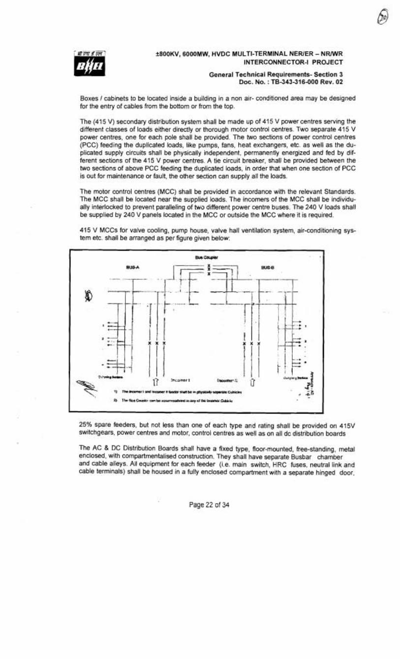
f800KVl 6000MW1 HVDC MULTI-TERMINAL NEWER - N W R INTERCONNECTOR-I PROJECT
General Technical Requirements- Section 3 Doc. No. : TB-343-316-000 Rev. 02
Boxes 1 cabinets to be located inside a building in a non air- conditioned area may be designed for the entry of cables from the bottom or from the top.
The (41 5 V) secondary distribution system shall be made up of 415 V power centres serving the different classes of loads either directly or thorough motor control centres. Two separate 41 5 V power centres, one for each pole shall be provided. The two sections of power control centres (PCC) feeding the duplicated loads, like pumps, fans, heat exchangers, etc. as well as the du- plicated supply circuits shall be physically independent, permanently energized and fed by dif- ferent sections of the 415 V power centres. A tie circuit breaker, shall be provided between the two sections of above PCC feeding the duplicated loads, in order that when one section of PCC is out for maintenance or fault, the other section can supply all the loads.
The motor control centres (MCC) shall be provided in accordance with the relevant Standards. The MCC shall be located near the supplied loads. The incomers of the MCC shall be individu- ally interlocked to prevent paralleling of twa different power centre buses. The 240 V loads shall be supplied by 240 V panels located in the MCC or outside the MCC where it is required.
415 V MCCs for valve cooling, pump house, valve hall ventilation system, air-conditioning sys- tem etc. shall be arranged as per figure given below:
25% spare feeders, but not less than one of each type and rating shall be provided on 415V switchgears, power centres and motor, control centres as well as on all dc distribution boards
The AC & DC Distribution Boards shall have a fixed type, floor-mounted, free-standing, metal enclosed, with compartmentalised construction. They shall have separate Busbar chamber and cable alleys. All equipment for each feeder (i.e. main switch, HRC fuses, neutral link and cable terminals) shall be housed in a fully enclosed compartment with a separate hinged door,
Page 22 of 34
+800KV, 6000MW, HVDC MULTI-TERMINAL NERlER - NRWR INTERCONNECTOR-I PROJECT
General Technical Requirements- Section 3 Doc. No. : TB-343-316-000 Rev. 02
such that fuse replacement, cable terminationlreplacement etc. are possible with complete safety, even if the Busbar and adjacent feeders are live. The connections from Busbar to the main switch shall be fully insulated/shrouded, and securely bolted. 'The partition between the feeder compartment and cable alley shall be non- metallic and shall be of such construction as to allow cable cores with lugs to be easily inserted in the feeder compartment for termination. Cable alley shall have no exposed live parts, and shall have no communication with Busbar chamber. The main switch shall be operated from outside, and shall be interlocked with the compartment door such that the latter can be opened only when the switch is OFF. However, it shall be possible to defeat this interlock and open and close the door with the switch ON. Bus- bar chamber shall be completely enclosed with metallic partitions. Bolted covers shall be pro- vided for access to horizontal and vertical Busbar and all joints, for repair and maintenance, which shall be feasible without disturbing the feeder compartment. Cable alley door shall pref- erably be hinged. The main switch shall have the facility of being pad- locked in both ON and OFF positions. The switch handle shall clearly indicate the position of main switch. The Sup- plier shall furnish suitable plugs to cover the cable openings in the partition between feeder compartment and cable alley, for at least 50% of the total number of feeders. The distribution boards shall have a degree of protection of at least IP52 as per IS-13947:Part 1.
All 415V switchgear (circuit breaker boards) shall be of single front type, with fully draw out cir- cuit breakers, which can be drawn out without having to unscrew any connections. The circuit breakers shall be mounted on rollers and guides for smooth movement between SERVICE, TEST and ISOLATED positions and for withdrawal from the Switchboard. Testing of the breaker shall be possible in the TEST position. Unless kept in OFF position it shall not be possible to withdraw the modules from service position or rack them into service position.
All outgoing feeders in distribution boards shall be through MCBsIMCCBs.
Circuit breakers shall be three pole air break horizontal draw out type and shall have inherent fault making and breaking capacities as specified. The circuit breakers which meet specified pa- rameter only after provision of releases or any other devices shall not be acceptable.
All circuit breakers shall be provided at least with 4 NO and 4 NC potentially free auxiliary con- tacts. These contacts shall be in addition to those required for internal mechanism of the breaker. Separate limit switches each having required number of contacts shall be provided in both 'SERVICE' & 'TEST' position of the breaker.
Control cabinets, junction boxes, Marshalling boxes and terminal boxes shall be made of sheet steel or aluminium enclosure.Sheet steel used shall be at least 2.0-mm thick cold rolled or 2.5 mm hot rolled. In case of aluminium enclosed box the thickness of aluminium shall be such that it provides adequate rigidity and long life as comparable with sheet sieel of specified thickness.
7. Earthing . The provision for earthing shall be generally as per requirements given in Clause 3.16.2
8. Tests
a) The Marshalling Kiosks shall be subject to routine tests as per IS: 5039
Page 23 of 34
+800KV, 6000MW, HVDC MULTI-TERMINAL NEWER - N W R INTERCONNECTOR-I PROJECT
General Technical Requirements- Section 3 Doc. No. : TB-343-316-000 Rev. 02
b) The following routine tests shall also be conducted:
i) Check for wiring
ii) Visual and dimension check
Marshalling kiosk shall be provided with danger plate and a diagram showing the numbering1 connection1 ferruling by pasting the same on the inside of the door.
Marshalling kiosk shall also be provided with incoming MCB and one 15 Amp interlocked switched socket in addition to the MCB required.
3.16 Indoor control cubicles
The control panel, cubicles and desks shall be in accordance with the relevant IEC standards and shall be installed in air-conditioned space. Indoor electronic cubicles shall not generally require fans for cooling in order to operate successfully and correctly at the maximum ambient temperature. However, if it is absolutely necessary to install fans etc. in cubicles for cooling then these shall be driven by the same dc supply as used for control, and necessary redundancy, failure alarm etc. shall be incorporated. Louvers in the doors and side panels shall be permitted, if required.
The control and relay panels shall be suitable for numerical relays o i modular type mounted in standard 19 inch racks located on the vertical front panel with rear doors for access or located on the front doors for front access type panels. Panels Cubicles shall be completely metal enclosed and shall be dust, moisture and vermin proof. The enclosure shall provide a degree of protection not less than IP 32 in accordance with IS-13947:Part I for cubicles located in air-conditioned areas. IP 31 may also be acceptable for these areas if the layout is arranged such that there is no possibility at all of any liquid entering the area. However, for ventilation reasons the cubicles may be provided with a ventilation hood at the top with a protection class of IP21.
Panels shall be free standing, floor mounting type and shall comprise structural frames enclosed completely with specially selected smooth finished, cold rolled sheet steel of thickness not less than 2.5 mm for weight bearing members of the cubicles such as base frame, front sheet and door frames, and 1.5 mm for sides, door top and bottom portions. There shall be sufficient reinforcement to provide level surfaces, resistance to vibration and rigidity during transportation and installation. The cubicles shall be provided with lifting lugs.
All doors, removable covers and plates shall be gasketed all around with neoprene gaskets. Ventila- tion louvers, if provided, shall have screens and filters. The screens shall be made of either brass or GI wire mesh with a graduation of 1 mm or less.
Design, material selection and workmanship shall be such as to result in a neat appearance, inside and outside with no welds rivets or bolt heads apparent from outside, with all exterior surfaces true and smooth. All cubicles located in any room shall be matched in appearance.
The Supplier along with anchor bolts and necessary hardware for mounting the cubicles shall furnish metal sills in the form of metal channels properly drilled. Panels shall have an additional rolled channel plinth at the bottom with a smooth bearing surface. The panels shall be fixed on channels with intervening layers of anti- vibration strips made of shock absorbing material, which shall be
Page 24 of 34
+800KV1 6000MW1 HVDC MULTI-TERMINAL NERlER - N W R INTERCONNECTOR-I PROJECT
General Technical Requirements- Section 3 Doc. No. : TB-343-316-000 Rev. 02
supplied by the Supplier.
Supplier's standard practice for control panels shall be acceptable to the Employer/Purchaser sub- ject to approval during detailed engineering and meeting all functional requirements of the specifica- tion.
3.16.1 Mounting
All equipment on and in panels shall be mounted and completely wired to the terminal blocks ready for external connections. The equipment on front of panel shall be mounted flush. No equipment shall be mounted on the doors.
Equipment shall be mounted such that removal and replacement can be accomplished individually without interruption of service to adjacent devices and are readily accessible without use of special tools. Terminal marking on the equipment shall be clearly visible.
The Supplier shall carry out cut out, mounting and wiring of the free issue items supplied by others, which are to be mounted in his panel in accordance with the corresponding equipment manufac- turet's drawings. Cut outs if any, provided for future mounting of equipment shall be properly blanked off with blanking plate.
The centre lines of switches, push buttons and indicating lamps shall be not less than 750mm from the bottom of the panel. The centre lines of relays, meters and recorders shall be not less than 450mm from the bottom of the panel
The centre lines of switches, push buttons and indicating lamps shall be matched to give a neat and uniform appearance. Like wise the top lines of all meters, relays and recorders etc. shall be matched.
No equipment shall be mounted on the doors.
At existing station, panels shall be matched with other panels in the control room in respect of dimensions, colour, appearance and arrangement of equipment (centre lines of switches, push buttons and other equipment) on the front of the panel.
3.16.2 Earthing
1) All panels shall be equipped with an earth bus securely fixed. Location of earth bus shall en- sure no radiation interference for earth systems ~inder various switching conditions of isolators and breakers. The material and the sizes of the bus bar shall be at least 25 X 6 sq. mm perfo- rated copper with threaded holes at a gap of 50mm with a provision of bolts and nuts for con- nection with cable armours and mounted equipment etc for effective earthing. When several panels are mounted adjoining each other, the earth bus shall be made continuous and neces- sary connectors and clamps for this purpose shall be included in the scope of supply of Sup- plier. Provision shall be made for extendirlg the earth bus bars to future adjoining panels on ei- ther side.
2) Provision shall be made on each bus bar of the end panels for connecting Substation earthing grid. Necessary terminal clamps and connectors for this purpose shall be included in the scope
Page 25 of 34

&800KV, 6000MW, HVDC MULTI-TERMINAL NEWER - NRWR INTERCONNECTOR-I PROJECT
General Technical Requirements- Section 3 Doc. No. : TB-343-316-000 Rev. 02
of supply of Supplier
3) All metallic cases of relays, instruments and other panel mounted equipment including gland plate, shall be connected to the earth bus by copper wires of size not less than 2.5 sq. mm. The colour code of earthing wires shall be green.
4) Looping of earth connections, which would result in loss of earth connection to other devices when the loop is broken, shall not be permitted. Earthing may be done in such a manner that no circulating current shall flow in the panel.
5) VT and CT secondary neutral or common lead shall be earthed at one place only at the terminal blocks where they enter the panel. Such earthing shall be made through links so that earthing may be removed from one group without disturbing continuity of earthing system for other groups.
6) An electrostatic discharge point shall be provided in each panel connected to earth bus via 1 Mega Ohm resistor.
3.16.3 Instruments, meters and recorders
Only digital displays and systems shall be provided. The requirements in this section are applicable to auxiliary systems only. All instruments, meters and recorders shall be enclosed in dust proof, moisture resistant, black finished cases and shall be suitable for tropical use. They shall be cali- brated to read directly the primary quantities. They shall be accurately adjusted and calibrated at the factory and shall have means of calibration, checking and adjustment at site.
3.1 6.4 Miscellaneous
1) 7he Supplier'shall submit all type and routine test certificates to the Employer & Purchaser for approval before dispatching the equipment. Control and relay panels shall also be subjected to the following tests: i) Mechanical operation test ii) Verification of degree of protection as per IS-I 3347:Part I iii) High voltage test iv) Electrical control, l nterlock and sequential operation test v) Verification of wiring as per approved schematic.
2) Plug Point: 240V, Single phase 50Hz, AC socket with switch suitable to accept 5 Amps and 15 Amps pin round standard Indian plug, shall be provided in the interior of each cubicle with ON- OFF switch.
3) Interior Lighting: Each panel shall be provided with a CFL lighting fixture rated for 240 Volts, single phase, 50 Hz supply for the interior illumination of the panel controlled by the respective panel door switch. Adequate lighting shall also be provided for the corridor in Duplex panels.
4) MC B's: Each panel shall be provided with necessary arrangements for receiving, distributing and isolating of DC and AC supplies for various control, signalling, lighting and space heater cir- cuits. The incoming and sub-circuits shall be separately provided with miniature circuit breakers (MCB).
Page 26 of 34
f800KV, 6000MW, HVDC MULTI-TERMINAL NEWER - N W R INTERCONNECTOR-I PROJECT
General Technical Requirements- Section 3 Doc. No. : TB-343-316-000 Rev. 02
5) Space Heater: Panels wherever required shall be provided with a space heater rated for 240V single phase, 50 Hz Ac supply for the internal heating of the panel to prevent condensation of moisture. The fittings shall be complete with thermostat and switch fuse IMCB unit.
3.16.5 Terminal blocks and wiring
All internal wiring to be connected to external equipment shall terminate on terminal blocks. Terminal blocks shall be 650 V grade and have 10 Amps. Continuous rating, moulded piece, com- plete with insulated barriers, stud type terminals, washers, nuts and lock nuts. Markings on the ter- minal blocks shall correspond to wire number and terminal numbers on the wiring diagrams. All terminal blocks shall have shrouding with transparent unbreakable material.
Disconnecting type terminal blocks for current transformer and voltage transformer secondary leads shall be provided. Also current transformer secondary leads shall be provided with short cir- cuiting and earthing facilities.
Spare terminals for Employer's use for upgrading to 6000 MW shall be provided wherever required. In addition, at least 20% spare terminals shall be provided on each panel and these spare terminals shall be uniformly distributed on all terminal blocks.
The terminal blocks shall be suitable for connecting the conductors of external cable on each side.
Terminal blocks shall be of (at least) 650V grade and have 10 amps continuous rating. These shall be moulded, complete with insulated barriers, stud type terminals, complete with washers, nuts and lock nuts. Screw clamp, overall insulated, insertion type, rail mounted terminals can be used in place of stud terminals with locking type. The terminal blocks shall be of reputed make subject to Employer's acceptance.
Terminal block design shall include a white fibre marking strip with clear" Gastic, Iclip-on terminal covers. Markings on the terminal strips shall correspond to wire numbers on the wiring diagrams.
Terminal blocks for current transformer and voltage transformer secondary leads shall be pro- vided with test links and isolating facilities. The current transformer secondary leads shall also be provided with short-circuiting and earthing facilities.
The conducting part in contact with the cable shall preferably be tinned or silver-plated however; nickel-plated copper shall also be acceptable. Insulating barriers shall be provided between the terminal blocks.
Manufacturer's standard practice for internal wiring of cubicles shall be acceptable to the Employer. However all external cabling requirements shall be strictly as per TS.
The Supplier shall furnish all wire, conduits and terminals for the necessary inter-phase electrical connections (where applicable) as well as between phases and common terminal boxes or control cabinets.
Page 27 of 34
+800KV, 6000MW, HVDC MUCl7-TERMINAL NEWER - N W R INTERCONNECTOR-I PROJECT
General Technical Requirements- Section 3 Doc. No. : TB-343-316-000 Rev. 02
3.17 Degree of protection
The enclosures of the control cabinets, Junction boxes and Marshalling boxes, panels etc. to be in- stalled as detailed here under:
The minimum requirements for panels are as follows:
lnstalled out door: IP- 55 lnstalled indoors in air-conditioned area: IP-32 lnstalled in covered area: IP-52 lnstalled indoors in non air-conditioned area where possibility of entry of water is limited: IP-41. For LT Switchgear (AC & DC distribution Boards): IP-52.
The degree of protection shall be in accordance with IS:13947 (Part-I) I IEC-947 (Part-I) I IS 12063 1 IEC 529. Type test report for degree of protection test, on each type of the box shall be submitted for approval
3.18 Welding and welders' qualifications
All welding shall be in accordance with the corresponding standards of the American Welding Soci- ety or the American Society of Mechanical Engineers. Welding shall comply with powergrid ap- proved quality plan.
Other standards to determine the quality of welding processes and qualifications of welders may be considered, provided that sufficient information is first submitted for the approval of the Employer.
Prior to the start of fabrication, the Supplier shall submit to the Employer for approval, a description of each of the welding procedures which he proposes to adopt, together with certified copies of re- ports of the results from tests made in accordance with these procedures.
The Supplier shall be responsible for the quality of the work performed by his welding organization. All welding operators shall be assigned to the work, including for repair of castings, shall pass the required tests for qualification of welding procedures. The Employer reserves the right to wit- ness the qualification tests for welding procedures and operators and the mechanical tests of the samples. If the lnspector so requires, the Supplier shall furnish to the lnspector certified copies of reports of the mechanical test results of the samples.
The Supplier shall bear all his own expenses in connection with the qualification tests. If the work of any operator at any time appears questionable, such operator shall be required to pass appro- priate re-qualification tests as specified by the lnspector and at the expense of the Supplier.
Strict measures for quality control shall be exercised throughout the EquipmenWorks. The Engi- neer may call for an adequate NDT test of the work of any operator, who, in his opinion, is not main- taining the required standard of workmanship. Should this NDT test prove defective, all work done by that operator, since his last test shall be tested at the Supplier's expense. If three or more of these tests prove defective, the operator shall be removed from the project.
A procedure for the repair of defects shall be submitted to the Employer for his approval prior to any
Page 28 of 34
+800KV, 6000MW, HVDC MULTI-TERMINAL NEWER - NRMlR INTERCONNECTOR-I PROJECT
General Technical Requirements- Section 3 Doc. No. : TB-343-316-000 Rev. 02
repairs being made.
3.19 Motors
All motors shall conform to IEC-60034-5 I IS Standard and with principal dimensions in accordance with IEC 60072-1 (1991), IEC 60072-2 (1990) and IEC 60072-3 (1994).
Motors rated 0.5 kW and above, and reversing motors, shall be rated 415 V, three phase, grounded neutral;
Motors rated below 0.5 kW shall be rated 240 V one phase;
All motors shall be designed to operate at full load dynamic conditions with a voltage range of varia- tion of +1 OOh, -20% and a frequency range variation of +5%,-10%. Motors shall also be designed to operate at 125% of the rated speed without mechanical damage, and to start with 80% of their rated voltage;
All motors shall be designed and rated for continuous operation at maximum ambient temperature of 50oC. The class of insulation shall be at least one class higher than used for defining the temperature rise of the motor;
Vertical motors rated 60 kW and above shall be provided with oil-lubricated self-cooled pivoted shoe-type thrust bearing. Vertical motors below 60 kW shall be provided with re- greasable anti-friction ball or roller bearings;
All anti-friction bearings shall be guaranteed to operate successfully for a minimum of 131,000 hours;
All bearings shall be quiet operating and statically and dynamically balanced;
All belts to be used shall be "\r' type and designed for the maximum power to be transmitted and for the maximum speed. The selection of the "V' belt drive for any application shall also be based on the nature of the load and the type of the driving unit. Belts installed outdoors shall be suitably pro- tected.
3.20 Conduits, pipes and accessories
The Supplier shall supply and install all rigid conduits, mild steel pipes, flexible conduits, hume pipes etc. including all necessary sundry materials, such as tees, elbows, check-nuts, bushings, reducers, enlargers, wooden plugs, coupling caps, nipples, gland sealing fittings, pull boxes etc. The size of the conduitlpipe shall be selected to limit the fill to a maximum of 40%. All conduitslpipes shall have their ends closed by caps until cables are pulled. After cables are pulled, the ends of conduitslpipes shall be sealed in an approved manner to prevent damage to threaded portions and en- trance of moisture and foreign materials.
PVC conduits shall be of high impact, heavy gauge (at least class 2) conduit conforming to BS-4607.
The outer surface of the steel conduits shall be coated with hot-dip zinc and chromate conversion coatings. The inner surface shall have silicone epoxy ester coating for easy cable pulling. Mild steel
Page 29 of 34
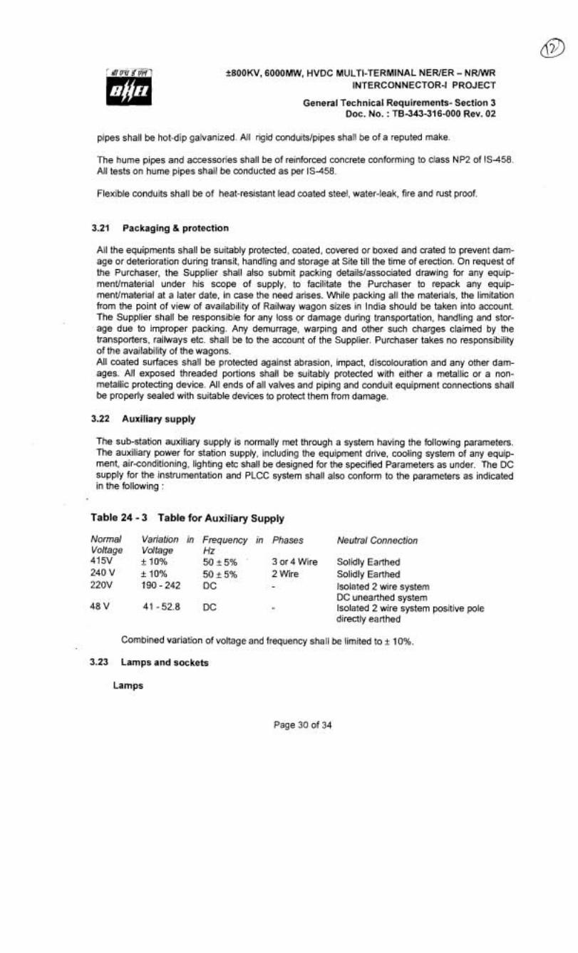
?800KV, 6000MW, HVDC MLILTI-TERMINAL NEWER - N W R INTERCONNECTOR-I PROJECT
General Technical Requirements- Section 3 Doc. No. : TB-343-316-000 Rev. 02
pipes shall be hot-dip galvanized. All rigid conduitslpipes shall be of a reputed make.
The hume pipes and accessories shall be of reinforced concrete conforming to class NP2 of 18-458. All tests on hume pipes shall be conducted as per 18-458.
Flexible conduits shall be of heat-resistant lead coated steel, water-leak, fire and rust proof.
3.21 Packaging & protection
All the equipments shall be suitably protected, coated, covered or boxed and crated to prevent dam- age or deterioration during transit, handling and storage at Site till the time of erection. On request of the Purchaser, the Supplier shall also submit packing detailslassociated drawing for any equip- menumaterial under his scope of supply, to facilitate the Purchaser to repack any equip- menumaterial at a later date, in case the need arises. While packing all the materials, the limitation from the point of view of availability of Railway wagon sizes in India should be taken into account. The Supplier shall be responsible for any loss or damage during transportation, handling and stor- age due to improper packing. Any demurrage, warping and other such charges claimed by the transporters, railways etc. shall be to the account of the Supplier. Purchaser takes no responsibility of the availability of the wagons. All coated surfaces shall be protected against abrasion, impact, discolouration and any other dam- ages. All exposed threaded portions shall be suitably protected with either a metallic or a non- metallic protecting device. All ends of all valves and piping and conduit equipment connections shall be properly sealed with suitable devices to protect them from damage.
3.22 Auxiliary supply
The sub-station auxiliary supply is normally met through a system having the following parameters. The auxiliary power for station supply, including the equipment drive, cooling system of any equip- ment, air-conditioning, lighting etc shall be designed for the specified Parameters as under. The DC supply for the instrumentation and PLCC system shall also conform to the parameters as indicated in the following :
Table 24 - 3 Table for Auxil iary Supply
Normal Variation in Frequency in Phases Neutral Connection Voltage Voltage Hz 41 5V + 10% 50 + 5% 3 or 4 Wire Solidly Earthed 240 V + 10% 50 + 5% 2 Wire Solidly Earthed 220V 190 - 242 DC Isolated 2 wire system
DC unearthed system 48 V 41 -52.8 DC Isolated 2 wire system positive pole
directly earthed
Combined variation of voltage and frequency shall be limited to + 10%.
3.23 Lamps and sockets
Lamps
Page 30 of 34

+800KV, 6000MW, HVDC MLILTI-TERMINAL NEWER - N W R INTERCONNECTOR-I PROJECT
General Technical Requirernents- Section 3 Doc. No. : TB-343-316-000 Rev. 02
All incandescent larnps shall use a socket base as per IS-1258, except in the case of signal lamps.
Sockets
All sockets (convenience outlets) shall be suitable to accept both 5 Amp & 15 Amp pin round Standard Indian plugs. They shall be switched sockets with shutters. Degree of pro- tection for outdoor switch sockets shall be IP55.
Hand Lamp
A 240 Volts, single Phase, 50 Hz AC plug point shall be provided in the interior of each cu- bicle with ON-OFF Switch for connection of hand larnps.
Switches and Fuses
Each panel shall be provided with necessary arrangements for receiving, distributing, isolating and fusing of DC and AC supplies for various control, signalling, lighting and space heater cir- cuits. The incoming and sub-circuits shall be separately provided with switchfuse units. Se- lection of the main and Sub-circuit fuse ratings shall be such as to ensure selective clearance of sub-circuit faults. Potential circuits for relaying and metering shall be protected by HRC fuses. All fuses shall be of HRC cartridge type conforming to IS9228 mounted on plug-in type fuse bases. Miniature circuit breakers with thermal protection and alarm contacts will also be accepted. All accessible live connection to fuse bases shall be adequately shrouded. Fuses shall have operation indicators for indicating blown fuse condition. Fuse carrier base shall have imprints of the fuse rating and voltage.
3.24 Availability spares
The Supplier shall supply the spare parts required to meet the specified guaranteed availability, and shall include such spare parts in the scope of supply. The detailed lists of spare parts to meet the guaranteed reliability & availability requirements shall be part of the contract documents. However if it is found during detailed engineering and/or Reliability & Availability prediction calculation that addi- tional spares are required to meet target values, the same shall be made available by the Supplier without any additional cost to the Employer.
3.25 Commissioning spares
The Supplier shall supply additional spares which he expects to consume duiing installation, testing and commissioning of the systems. The quantity of these spares shall be decided based on his pre- vious experience, such that site work shall not be hampered due to non-availability of these spares.
3.26 Tools & tackles
The Supplier shall also supply at each site one set of all special tools & tackles, testing equipment, handling equipment, etc. which are required by the Employer's maintenance staff to maintain the stations successfully.
3.27 Seismic force consideration
Page 31 of 34
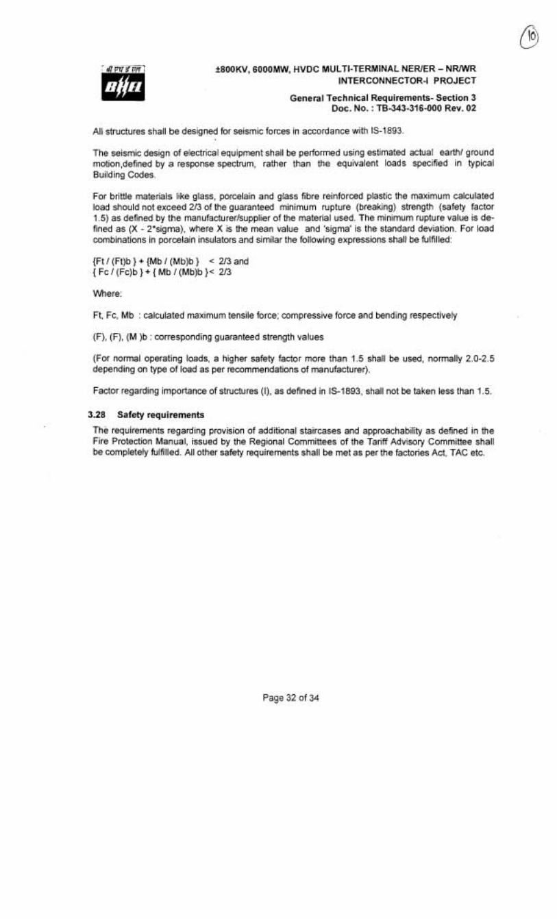
f 800KV, 6000MW, HVDC MULTI-TERMINAL NEWER - N W R INTERCONNECTOR-I PROJECT
General Technical Requirements- Section 3 Doc. No. : TB-343-316-000 Rev. 02
All structures shall be designed for seismic forces in accordance with IS-1893.
The seismic design of electrical equipment shall be performed using estimated actual earth1 ground motion,defined by a response spectrum, rather than the equivalent loads specified in typical Building Codes.
For brittle materials like glass, porcelain and glass fibre reinforced plastic the maximum calculated load should not exceed 213 of the guaranteed minimum rupture (breaking) strength (safety factor 1.5) as defined by the manufacturerlsupplier of the material used. The minimum rupture value is de- fined as (X - 2'sigma), where X is the mean value and 'sigma' is the standard deviation. For load combinations in porcelain insulators and similar the following expressions shall be fulfilled:
{Ft I (Ft)b } + {Mb I (Mb)b } < 213 and { Fc 1 (Fc)b } + { Mb 1 (Mb)b )< 213
Where:
Ft, Fc, Mb : calculated maximum tensile force; compressive force and bendirlg respectively
(F), (F), (M )b : corresponding guaranteed strength values
(For normal operating loads, a higher safety factor more than 1.5 shall be used, normally 2.0-2.5 depending on type of load as per recommendations of manufacturer).
Factor regarding importance of structures (I), as defined in IS-1893, shall not be taken less than 1.5.
3.28 Safety requirements
The requirements regarding provision of additional staircases and approachability as defined in the Fire Protection Manual, issued by the Regional Committees of the Tariff Advisory Committee shall be completely fulfilled. All other safety requirements shall be met as per the factories Act, TAC etc.
Page 32 of 34

f 800KV, 6000MW, HVDC MULTI-TERMINAL NERlER - N W R INTERCONNECTOR-I PROJECT
General Technical Requirements- Section 3 Doc. No. : TB-343-316-000 Rev. 02
ANNEXURE-A Corona and Radio Interference Voltage (RIV) Test
General
Unless otherwise stipulated, all equipment (except Auto Transformer & Shunt Reactor) to- gether with its associated connectors, where applicable, shall be tested for external corona both by observing the voltage level for the extinction of visible corona under falling power fre- quency voltage and by measurement of radio interference voltage (RIV). The test procedure shall be reviewed for different equipment during submission of MQPIITP.
Test Levels:
The test voltage levels for measurement of external RIV and for corona extinction voltage are listed under the relevant clauses of the specification.
Test Methods for RIV:
RIV tests shall be made according to measuring circuit as per International Special-Committee on Radio lnterference (CISPR) Publication 16-l(1993) Part -1. The measuring circuit shall preferably be tuned to frequency with 10% of 0.5 Mhz but other frequencies in the range of 0.5 MHz to 2 MHz may be used, the measuring frequency being recorded. The results shall be in microvolts.
Alternatively, RIV tests shall be in accordance with NEMA standard Publication No. 107-1 964, except otherwise noted herein.
In measurement of, RIV, temporary additional external corona shielding may be provided. In measurements of RIV only standard fittings of identical type supplied with the equipment and a simulation of the connections as used in the actual installation will be permitted in the vicinity within 3.5 meters of terminals.
Ambient noise shall be measured before and after each series of tests to ensure that there is no variation in ambient noise level. If variation is present, the lowest ambient noise level will form basis for the measurements. RIV levels shall be measured at increasing and decreasing voltages of 85%, loo%, 115% and 130% of the specified RIV test voltage for all equipment unless otherwise specified. The specified RIV test voltage for 400 kV, 220 kV is listed in the detailed specification together with maximum permissible RIV level in microvolts.
The metering instruments shall be as per CISPR recommendation or equivalent device so long as it has been used by other testing authorities.
The RIV measurement may be made with a noise meter. A calibration procedure of the fre- quency to which noise meter shall be tuned shall establish the ratio of voltage at the high volt- age terminal to voltage read by noise level meter.
Test Methods for Visible Corona
The purpose of this test is to determine the corona extinction voltage of apparatus, connectors etc. The test shall be carried out in the same manner as RIV test described above with the ex- ception that RIV measurements are not required during test and a search technique shall be used near the onset and extinction voltage, when the test voltage is raised and lowered to de- termine their precise values. The test voltage shall be raised to 130% of RIV test voltage and maintained there for five minutes. In case corona inception does not take place at 130 %, test
Page 33 of 34
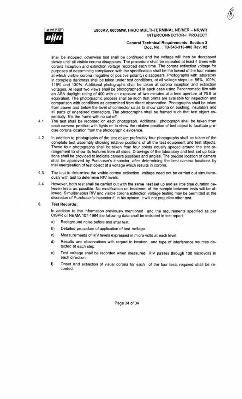
f800KV, 6000MW, HVDC MUCTI-TERMINAL NEWER - N W R INTERCONNECTOR-I PROJECT
General Technical Requirements- Section 3 Doc. No. : TB-343-316-000 Rev. 02
shall be stopped, otherwise test shall be continued and the voltage will then be decreased slowly until all visible corona disappears. The procedure shall be repeated at least 4 times with corona inception and extinction voltage recorded each time. The corona extinction voltage for purposes of determining compliance with the specification shall be the lowest of the four values at which visible corona (negative or positive polarity) disappears. Photographs with laboratory in complete darkness shall be taken under test conditions, at all voltage steps i.e. 85%, loo%, 115% and 130%. Additional photographs shall be taken at corona inception and extinction voltages. At least two views shall be photographed in each case using Panchromatic film with an ASA daylight rating of 400 with an exposure of two minutes at a lens aperture of f15.6 or equivalent. The photographic process shall be such that prints are available for inspection and comparison with conditions as determined from direct observation. Photographs shall be taken from above and below the level of connector so as to show corona on bushing, insulators and all parts of energised connectors. The photographs shall be framed such that test object es- sentially, fills the frame with no cut-off.
4.1 The test shall be recorded on each photograph. Additonal photograph shall be taken from each camera position with lights on to show the relative position of test object to facilitate pre- cise corona location from the photographic evidence.
4.2 In addition to photographs of the test object preferably four photographs shall be taken of the complete test assembly showing relative positions of all the test equipment and test objects. These four photographs shall be taken from four points equally spaced around the test ar- rangement to show its features from all sides. Drawings of the laboratory and test set up loca- tions shall be provided to indicate camera positions and angles. The precise location of camera shall be approved by Purchaser's inspector, after determining the best camera locations by trial energisation of test object at a voltage which results in corona.
4.3 The test to determine the visible corona extinction voltage need not be carried out simultane- ously with test to determine RIV levels.
4.4 However, both test shall be carried out with the same test set up and as little time duration be- tween tests as possible. No modification on treatment of the sample between tests will be al- lowed. Simultaneous RIV and visible corona extinction voltage testing may be permitted at the discretion of Purchaser's inspector if, in his opinion, it will not prejudice other test.
5. Test Records:
In addition to the information previously mentioned and the requirements specified as per ClSPR or NEMA 107-1964 the following data shall be included in test report:
a) Background noise before and after test.
b) Detailed procedure of application of test vo!tage.
c) Measurements of RIV levels expressed in micro volts at each level
d) Results and observations with regard to location and type of interference sources de- tected at each step.
e) Test voltage shall be recorded when measured RIV passes through 100 microvolts in each direction.
f) Onset and extinction of visual corona for each of the four tests required shall be re- corded.
Page 34 of 34