bell 412sp pilot training manual volume 1, revision...
TRANSCRIPT

COURSEWARE SUPPORT—HURST 8900 Trinity Blvd. Hurst, Texas 76053 (817) 276-7500 Fax (817) 276-7501
BELL 412 PILOT TRAINING MANUAL VOLUME 1
Record of Revision No. 1
This is a complete reprint of the Bell 412 Pilot Training Manual.
The portion of the text or figure affected by this revision is indicated by asolid vertical line in the margin. A vertical line adjacent to blank spacemeans that material has been deleted. In addition, each revised page ismarked “Revision 1” in the lower left or right corner.
The changes made in this revision will be further explained at theappropriate time in the training course.
FlightSafetyinternational
the best safety device in any aircraft is a well-trained crew. . .

FlightSafetyinternational
BELL 412PILOT
TRAININGMANUAL
VOLUME 1 — Operational Information
FlightSafety International, Inc.Marine Air Terminal, LaGuardia Airport
Flushing, New York 11371(718) 565-4100
www.flightsafety.com

Courses for the Bell 412 are taught at the followingFlightSafety learning center:
Fort Worth Bell Learning Center9601 Trinity BoulevardHurst, Texas 76053(817) 282-2557(800) 379-7413
Copyright © 1996 by FlightSafety International, Inc. All rightsreserved. Printed in the United States of America.
ii FOR TRAINING PURPOSES ONLY

iii
NOTICE
The material contained in this training manual is based on informationobtained from the aircraft manufacturer ’s Pilot Manuals andMaintenance Manuals. It is to be used for familiarization and trainingpurposes only.
At the time of printing it contained then-current information. In the eventof conflict between data provided herein and that in publications issuedby the manufacturer or the FAA, that of the manufacturer or the FAAshall take precedence.
We at FlightSafety want you to have the best training possible. Wewelcome any suggestions you might have for improving this manual orany other aspect of our training program.
FOR TRAINING PURPOSES ONLY
FOR TRAINING PURPOSES ONLY

VOLUME 1—OPERATIONAL INFORMATION
CONTENTS
EXPANDED CHECKLIST
Normal Procedures
Emergency/Malfunction Procedures
LIMITATIONS
MANEUVERS AND PROCEDURES
WEIGHT AND BALANCE
PERFORMANCE
CRM
MASTER WARNING SYSTEM
SYSTEMS REVIEW
Revision 1

The information normally contained in this chapter is
not applicable to this particular aircraft.
EXPANDED CHECKLISTSCONTENTS
Page
GENERAL INFORMATION............................................................ EC-1
Introduction.............................................................................. EC-1
Operating Limitations .............................................................. EC-1
Flight Planning......................................................................... EC-1
Preflight Check ........................................................................ EC-2
PREFLIGHT GENERAL—NORMAL PROCEDURES ............................................................... EC-4
Before Exterior Check ............................................................. EC-4
Exterior Check ......................................................................... EC-7
Interior Check ........................................................................ EC-23
FOR TRAINING PURPOSES ONLY EC-i
FlightSafety International
BELL 412 P I L O T T R A I N I N G M A N U A L

ILLUSTRATIONFigure Title Page
EC-1 Preflight Check Sequence ............................................... EC-3
FOR TRAINING PURPOSES ONLY EC-iii
FlightSafety International
BELL 412 P I L O T T R A I N I N G M A N U A L

EXPANDED CHECKLISTS
GENERAL INFORMATIONINTRODUCTIONThis section contains instructions and procedures for operating the helicopterfrom the planning stage, through actual flight conditions, to securing the he-licopter after landing.
Normal and standard conditions are assumed in these procedures. Pertinentdata in other sections is referenced when applicable.
The instructions and procedures contained herein are written for the purposeof standardization and are not applicable to all situations.
OPERATING LIMITATIONSThe minimum and maximum limits, and the normal and cautionary operat-ing ranges for the helicopter and its subsystems are indicated by instrumentmarkings and placards.
Anytime an operating limitation is exceeded, an appropriate entry shall bemade in the helicopter logbook. The entry shall state which limit was exceeded,the duration of time, the extreme value attained, and any additional informationessential in determining the maintenance action required.
These instrument markings and placards represent careful aerodynamic cal-culations that are substantiated by flight test data.
Refer to Limitations and Specifications chapter for a detailed explanation ofeach operating limitation.
FLIGHT PLANNINGEach flight should be planned adequately to ensure safe operations and to pro-vide the pilot with the data to be used during flight.
Essential weight and balance, and performance information should be com-piled as follows:
• Check type of flight to be performed and destination.
• Select appropriate performance charts (see Performance chapter).
Takeoff and Landing DataRefer to the RFM Limitations chapter for Takeoff and Landing Weight Limits,and to the Performance chapter for Takeoff and Landing Distance Information.
FOR TRAINING PURPOSES ONLY EC-1
FlightSafety International
BELL 412 P I L O T T R A I N I N G M A N U A L

Weight and BalanceDetermine proper weight and balance of the helicopter as follows:
• Consult the “Weight and Balance” section of the Rotocraft FlightManual for instructions (see Weight and Balance chapter of this manual).
• Compute takeoff and anticipated landing gross weight, check helicopter(CG) locations, and ascertain weight of fuel, oil, payload, etc.
• Check that loading limitations listed in the Limitations chapter havenot been exceeded.
PREFLIGHT CHECKThe pilot is responsible for determining whether the helicopter is in condi-tion for safe flight. Refer to Figure EC-1 for preflight check sequence.
NOTEThe pilot walkaround and interior checks are outlinedin the following procedures. The preflight check isnot intended to be a detailed mechanical inspection, butsimply a guide to help the pilot check the condition ofthe helicopter. It may be made as comprehensive asconditions warrant at the discretion of the pilot.
All areas checked shall include a visual check for ev-idence of corrosion, particularly when helicopter isflown near or over salt water or in areas of highindustrial emissions.
EC-2 FOR TRAINING PURPOSES ONLY Revision 1
FlightSafety International
BELL 412 P I L O T T R A I N I N G M A N U A L

FOR TRAINING PURPOSES ONLY EC-3
FlightSafety International
BELL 412 P I L O T T R A I N I N G M A N U A L
Figure EC-1. Preflight Check Sequence

PREFLIGHT GENERAL—NORMAL PROCEDURESBEFORE EXTERIOR CHECK
1. Flight Planning .................................................................... COMPLETED
2. Gross Weight and CG............................................................... COMPUTE
Refer to the Weight and Balance section in the Rotocraft Flight Manual.
3. Publications .............................................................................. CHECKED
4. Portable Fire Extinguishers ................................................... CONDITIONAND SECURITY
5. Fuel Sumps ..................................................................................... DRAIN
Samples as follows:
a. FUEL TRANS Switches................................................................. OFF
b. BOOST PUMP Switches ................................................................ OFF
c. FUEL Switches ............................................................................... OFF
EC-4 FOR TRAINING PURPOSES ONLY Revision 1
FlightSafety International
BELL 412 P I L O T T R A I N I N G M A N U A L
412SP, HP, EP 412

c. BAT BUS 1 Switch........................................................................... ON
d. Fuel Sump DrainButtons (left and right) —Aft/Middle/Forward .................... DEPRESS
6. Fuel Filters ...................................................................................... DRAIN
Before first flight of day, as follows:
a. BOOST PUMP Switches.................................................................. ON
b. FUEL Switches................................................................................. ON
Revision 1 FOR TRAINING PURPOSES ONLY EC-5
FlightSafety International
BELL 412 P I L O T T R A I N I N G M A N U A L
412SP, HP, EP 412

c. Fuel Filter (left and right) ....................................... DRAIN SAMPLES
d. FUEL Switches ............................................................................... OFF
e. BOOST PUMP Switches ................................................................ OFF
f. BAT BUS 1 Switch ......................................................................... OFF
g. Main and tail rotor blade tie down.....................REMOVE AND STOW
h. Pitot tube cover(s)..............................................REMOVE AND STOW
i. No. 1 and 2 engine air intake covers..................REMOVE AND STOW
EC-6 FOR TRAINING PURPOSES ONLY Revision 1
FlightSafety International
BELL 412 P I L O T T R A I N I N G M A N U A L
412SP, HP, EP 412
EXTERIOR CHECK
IF HELICOPTER HAS BEEN EXPOSED TO SNOWOR ICING CONDITIONS, SNOW AND ICE SHALLBE REMOVED PRIOR TO FLIGHT.
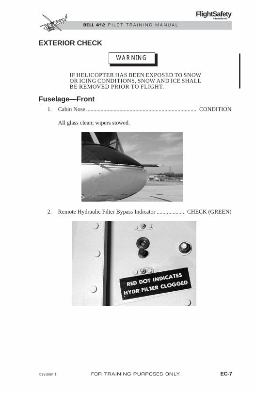
Fuselage—Front1. Cabin Nose ............................................................................ CONDITION
All glass clean; wipers stowed.
2. Remote Hydraulic Filter Bypass Indicator ................... CHECK (GREEN)
WARNING
Revision 1 FOR TRAINING PURPOSES ONLY EC-7
FlightSafety International
BELL 412 P I L O T T R A I N I N G M A N U A L

3. Circuit Breakers....................................................................... CHECK (IN)
Transmission ChipDetector Indicators ........................................................................ CHECK
4. Pitot Tube(s) ........................................................ COVER(S) REMOVED;
EC-8 FOR TRAINING PURPOSES ONLY Revision 1
FlightSafety International
BELL 412 P I L O T T R A I N I N G M A N U A L

UNOBSTRUCTED
5. Static Ports (left and right)........................................... UNOBSTRUCTED
6. Rotor Blade (forward) ................... CONDITIONS AND CLEANLINESS
Revision 1 FOR TRAINING PURPOSES ONLY EC-9
FlightSafety International
BELL 412 P I L O T T R A I N I N G M A N U A L

7. Cabin Nose Ventilators ................................................ UNOBSTRUCTED
8. Nose Compartment....................................................................... SECURE
9. Battery Vent and Drain Tubes...................................... UNOBSTRUCTED
10. Searchlight and Landing Light ................................................... STOWED
11. Antennas ...................................................................... CONDITION ANDSECURITY
EC-10 FOR TRAINING PURPOSES ONLY Revision 1
FlightSafety International
BELL 412 P I L O T T R A I N I N G M A N U A L

Fuselage—Cabin left side1. Copilot Door......................................... CONDITION AND OPERATION
Glass clean. Check security of emergency release handles.
..2.Position Lights...............................CONDITION
3. Passenger Door..................................... CONDITION AND OPERATION
Glass clean. Condition of pop-out windows.
Revision 1 FOR TRAINING PURPOSES ONLY EC-11
FlightSafety International
BELL 412 P I L O T T R A I N I N G M A N U A L

4. Landing Gear......................................................................... CONDITION
Handling wheels removed.
5. Passenger Step (if installed) .................... CONDITION AND SECURITY
Fuselage—Aft left side1. No. 1 Engine Compartment ........................................................... CHECK
2. No. 1 Engine Oil Level ........................... VERIFY ACTUAL PRESENCEOF OIL IN SIGHT GAGE
Visually check oil level and filler cap
3. N2 Governor Spring ................................................ CHECK CONDITION
4. Engine Fire Extinguisher ............................................... CHECK BOTTLEPRESSURE GAGE AND
TEMPERATURE RANGE
EC-12 FOR TRAINING PURPOSES ONLY
FlightSafety International
BELL 412 P I L O T T R A I N I N G M A N U A L

5. Combining Gearbox Filter ............................................. CHECK BYPASSINDICATOR RETRACTED
6. Oil Cooler Blower........................................................ UNOBSTRUCTED
7. Avionics Compartment .......................... SECURITY OF COMPONENTS8. Access Doors and Engine Cowling ........................................... SECURED
9. Rotor Blade (left) ............................. CONDITION AND CLEANLINESS
Revision 1 FOR TRAINING PURPOSES ONLY EC-13
FlightSafety International
BELL 412 P I L O T T R A I N I N G M A N U A L

10. Drain Lines ........................................................................... CLEAN ANDUNOBSTRUCTED
12. Engine Exhaust Ejectors ........................................ COVERS REMOVED;UNOBSTRUCTED
13. Oil Coolers................................................................... UNOBSTRUCTED
Tailboom1. Tailboom .............................................................................. CONDITION;
ACCESS COVERS SECURED
2. Tail Rotor Driveshaft Covers..................................................... SECURED
EC-14 FOR TRAINING PURPOSES ONLY Revision 1
FlightSafety International
BELL 412 P I L O T T R A I N I N G M A N U A L

Do not bend elevator trailing edge tab.
3. Elevator........................................................................ CONDITION ANDSECURITY
Check for spring condition by moving elevator toward the leading edgedown position.
4. Tail Rotor (90°) Gearbox ............................................. VERIFY ACTUALPRESENCE OF OIL
IN SIGHT GAGE
Visually check oil level. Check filler cap, and chip detector plug for security.
5. Tail Rotor Blade............................... CONDITION AND CLEANLINESS
6. Tail Rotor .......................................................... CONDITION AND FREEMOVEMENT ONFLAPPING AXIS
7. Tail Rotor Yoke ...................................... CONDITION OF STATIC STOP
Evidence of static stop contact damage (deformed static stop yield indicator).
CAUTION
Revision 1 FOR TRAINING PURPOSES ONLY EC-15
FlightSafety International
BELL 412 P I L O T T R A I N I N G M A N U A L

8. Rotor Blade (aft) .............................. CONDITION AND CLEANLINESS
9. Tail Skid....................................................................... CONDITION ANDSECURITY
10. Intermediate (42°) gearbox .......................................... VERIFY ACTUALPRESENCE OF OIL
IN SIGHT GAGE
Visually check oil level. Check filler cap and chip detector plug for security.
11. Elevator........................................................................ CONDITION ANDSECURITY
12. Tailboom................................................................................ CONDITION
EC-16 FOR TRAINING PURPOSES ONLY Revision 1
FlightSafety International
BELL 412 P I L O T T R A I N I N G M A N U A L

13. Baggage Compartment.............................................. CARGO SECURED;SMOKE DETECTOR
CONDITION;DOOR SECURED
Fuselage—Aft Right Side1. Rotor Blade (right) .................................................. REMOVE TIEDOWN
Visually check condition and cleanliness.
2. Aft Compartment ........................................................................... CHECKUNOBSTRUCTED
3. Tail Rotor Actuator ........................................................................ CHECK
Revision 1 FOR TRAINING PURPOSES ONLY EC-17
FlightSafety International
BELL 412 P I L O T T R A I N I N G M A N U A L

4. Engine Fire Extinguisher ............................................... CHECK BOTTLEPRESSURE GAGE AND
TEMPERATURE RANGE
5. Combining Gearbox Oil Level ..................................... VERIFY ACTUALPRESENCE OF OIL
IN SIGHT GAGE
6. Oil Cooler Blower........................................................ UNOBSTRUCTED
EC-18 FOR TRAINING PURPOSES ONLY Revision 1
FlightSafety International
BELL 412 P I L O T T R A I N I N G M A N U A L

7. No. 2 Engine Compartment ........................................................... CHECK
8. No. 2 Engine Oil Level ................................................ VERIFY ACTUALPRESENCE OF OIL
IN SIGHT GAGE
Visually check oil level and filler cap.
9. Access Doors andEngine Cowling......................................................................... SECURED
10. Fuel Filler .................................................................. VISUALLY CHECKQUANTITY; SECURED
Fuselage—Cabin Right Side1. Passenger Door ............................................................ CONDITION AND
OPERATION
Glass clean. Condition of pop-out windows.
Revision 1 FOR TRAINING PURPOSES ONLY EC-19
FlightSafety International
BELL 412 P I L O T T R A I N I N G M A N U A L
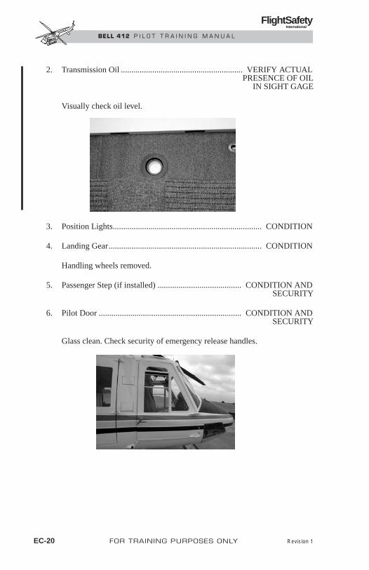
2. Transmission Oil .......................................................... VERIFY ACTUALPRESENCE OF OIL
IN SIGHT GAGE
Visually check oil level.
3. Position Lights....................................................................... CONDITION
4. Landing Gear......................................................................... CONDITION
Handling wheels removed.
5. Passenger Step (if installed) ........................................ CONDITION ANDSECURITY
6. Pilot Door .................................................................... CONDITION ANDSECURITY
Glass clean. Check security of emergency release handles.
EC-20 FOR TRAINING PURPOSES ONLY Revision 1
FlightSafety International
BELL 412 P I L O T T R A I N I N G M A N U A L

Cabin Top1. Hub and Sleeve Assembly ............................................................. CHECK
CONDITION
2. Swashplate, Support Assemblyand Collective Lever ...................................................................... CHECK
CONDITION
3. Main Rotor Pitch Links .................................................. SECURITY ANDCONDITION
4. Main Rotor Hub ................................................................... CHECK ANDGENERAL CONDITION
a. Mast Retaining Nut .............................................................. SECURED
b. Yoke Assembly ..................................................................CONDITION
Revision 1 FOR TRAINING PURPOSES ONLY EC-21
FlightSafety International
BELL 412 P I L O T T R A I N I N G M A N U A L
c. Pitch Horns..................................................................SECURITY ANDCONDITION
d. Elastomeric Bearings,Lead-Lag Dampers................................................ CHECK GENERAL
CONDITIONS
e. Blade Retention Bolts ............................................... SECURITY ANDPROPER LATCHING
f. Droop Restrainers ...................................................... SECURITY ANDCONDITION
g. Simple PendulumAbsorbers (if installed) ............................................. SECURITY AND
CONDITION
5. Rotor Blades .............................................................. VISUALLY CHECKCONDITION AND
CLEANLINESS
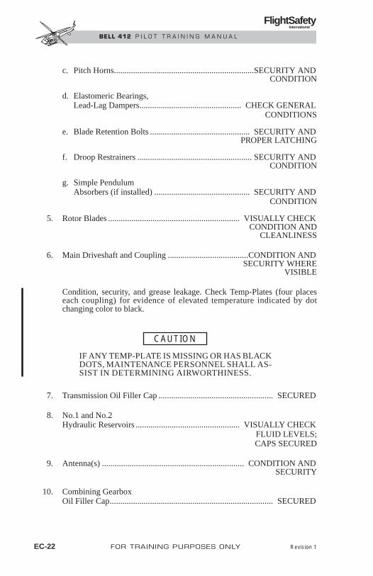
6. Main Driveshaft and Coupling ......................................CONDITION ANDSECURITY WHERE
VISIBLE
Condition, security, and grease leakage. Check Temp-Plates (four placeseach coupling) for evidence of elevated temperature indicated by dotchanging color to black.
IF ANY TEMP-PLATE IS MISSING OR HAS BLACKDOTS, MAINTENANCE PERSONNEL SHALL AS-SIST IN DETERMINING AIRWORTHINESS.
7. Transmission Oil Filler Cap ...................................................... SECURED
8. No.1 and No.2Hydraulic Reservoirs ................................................. VISUALLY CHECK
FLUID LEVELS;CAPS SECURED
9. Antenna(s) ................................................................... CONDITION ANDSECURITY
10. Combining GearboxOil Filler Cap............................................................................. SECURED
CAUTION
EC-22 FOR TRAINING PURPOSES ONLY Revision 1
FlightSafety International
BELL 412 P I L O T T R A I N I N G M A N U A L

11. Anticollision Light....................................................... CONDITION ANDSECURITY
12. No. 1 and No. 2Engine Air Intakes.................................................. COVERS REMOVED;
UNOBSTRUCTED
Check particle separator doors closed.
13. Engine and Transmission Cowling............................................ SECURED
14. Fresh Air Inlet Screen.................................................. UNOBSTRUCTED
15. Rotor Brake Reservoir Cap ...................................................... SECURITY
INTERIOR CHECK1. Cabin Interior.................................................................... CLEANLINESS
AND SECURITYOF EQUIPMENT
2. Cargo and Baggage(if applicable) ............................................................ CHECK SECURITY
3. Protective BreathingEquipment (if installed) ............................................... CONDITION AND
PROPERLY SERVICED
NOTEOpening or removing doors shifts helicopter centerof gravity and reduces VNE. Refer to Weight andBalance section in the Rotocraft Flight Manual (RFM)and t o Door s Open o r Removed i n t he RFMLimitations section.
4. Passenger Doors ........................................................................ SECURED
Go to the aircraft specific section of this chapter to complete checklist.
Revision 1 FOR TRAINING PURPOSES ONLY EC-23
FlightSafety International
BELL 412 P I L O T T R A I N I N G M A N U A L

NORMAL PROCEDURES—412SPCONTENTS
Page
INTERIOR CHECK ................................................................... NP-SP-1
Prestart Check ................................................................... NP-SP-1
Engine Starting .................................................................. NP-SP-5
Engine 1 Start .................................................................... NP-SP-5
Engine 2 Start .................................................................... NP-SP-8
False Start........................................................................ NP-SP-10
Systems Checks............................................................... NP-SP-11
BEFORE TAKEOFF ................................................................ NP-SP-21
Power Assurance Check.................................................. NP-SP-22
TAKEOFF................................................................................. NP-SP-23
IN-FLIGHT OPERATION ....................................................... NP-SP-24
Maneuvering with AFCS in SAS Mode.......................... NP-SP-24
Maneuvering with AFCS in ATT Mode.......................... NP-SP-24
BEFORE LANDING................................................................ NP-SP-24
AFTER LANDING .................................................................. NP-SP-25
ENGINE SHUTDOWN............................................................ NP-SP-26
AFTER EXITING HELICOPTER........................................... NP-SP-28
FOR TRAINING PURPOSES ONLY NP-SP-i
FlightSafety International
BELL 412 P I L O T T R A I N I N G M A N U A L

NORMAL PROCEDURES—412SP
INTERIOR CHECKPRESTART CHECK
1. Seat and Pedals ............................................................................. ADJUST
2. Seatbelt and Shoulder Harness............................................ FASTEN ANDADJUST
3. Shoulder Harness InertiaReel and Lock ................................................................................ CHECK
4. Directional Control Pedals......................................... CHECK FREEDOMOF MOVEMENT
Position for engine start.
5. Flight Controls..................................................... POSITION FOR START
Friction as desired.
6. Transmission ChipDetector Indicators......................................................................... CHECK
Reset if required.
7. Collective Switches .............................................................................. OFF
8. Lower Pedestal Circuit Breakers ............................................................. IN
9. Radio Equipment.................................................................................. OFF
10. COMPASS CONTROLSwitch(es) ............................................................................ MAG (SLAVE
POSITION)
11. FUEL INTCON Switch................................................................... NORM
12. FUEL TRANS Switches ...................................................................... OFF
13. BOOST PUMP Switches ..................................................................... OFF
14. FUEL XFEED Switch ..................................................................... NORM
15. ENGINE 1 and ENGINE 2 FUEL Switches........................................ OFF
Revision 1 FOR TRAINING PURPOSES ONLY NP-SP-1
FlightSafety International
BELL 412 P I L O T T R A I N I N G M A N U A L

16. PART SEP Switches ..........................................................................NORM
17. ENGINE 1 andENGINE 2 GOV Switches ............................................................... AUTO
18. HYDR SYS NO. 1 andNO. 2 Switches ...................................................................................... ON
19. STEP Switch (if installed) .................................................... AS DESIRED
20. FORCE TRIM Switch ............................................................ ON, COVERDOWN
21. Instruments ...................................................................... STATIC CHECK
22. STATIC SOURCESwitch (if installed) ............................................................................... PRI
23. APPROACH PLATE andMAP LIGHT Knob(s) .......................................................................... OFF
24. AUX SYS PITOT andSTATIC Switches (if installed)........................................................ NORM
25. Altimeter(s) ............................................................................................SET
26. Clock ....................................................................... SET AND RUNNING
27. FIRE EXT Switch ................................................................................ OFF
28. FIRE PULL Handles ........................................................ IN (FORWARD)
29. AFT DOME LIGHTRheostat and Switch............................................................................. OFF
30. PITOT STATICHEATERS Switch ................................................................................ OFF
31. WIPERS Switches................................................................................ OFF
32. CARGO RELEASESwitch (if installed) .............................................................................. OFF
33. HEATER Switch .................................................................................. OFF
34. AFT OUTLET Switch.......................................................................... OFF
NP-SP-2 FOR TRAINING PURPOSES ONLY Revision 1
FlightSafety International
BELL 412 P I L O T T R A I N I N G M A N U A L

35. VENT BLOWER Switch ..................................................................... OFF
36. EMERG LT Switch (if installed) ................................................. DISARM
37. STBY ATT Switch (if installed) ........................................................ TEST
Check standby attitude instrument light illuminates and OFF flag retractsmomentarily, then switch OFF.
38. WSHLD HEATSwitches (if installed)........................................................................... OFF
39. Overhead Circuit Breakers ...................................................................... IN
40. All LT Rheostats................................................................................... OFF
41. UTILITY LIGHT Switch..................................................................... OFF
42. POSITION Light.................................................................................. OFF
43. ANTI COLL Light................................................................................. ON
44. EMERG LOAD Switch.............................................................. NORMAL
45. NON-ESNTL BUS Switch.......................................... SPRING-LOADEDTO NORMAL
46. INV 1 and 2 Switches .......................................................................... OFF
47. GEN 1 and 2 Switches ......................................................................... OFF
NOTEIf external power is used—CONNECT (1,000 ampsmaximum). Check 27 ± 1 Volts DC; adjust powersource if required.
48. BATTERY Switches(BUS 1 and BUS 2) ............................................................................... ON
Check BATTERY caution light illuminates.
Revision 1 FOR TRAINING PURPOSES ONLY NP-SP-3
FlightSafety International
BELL 412 P I L O T T R A I N I N G M A N U A L

NOTETest operate all lights when night flights are plannedor anticipated. Accomplish light tests with externalpower connected or during engine runup.
49. ROTOR BRAKE Lights..................................................................... TEST
Pull brake ON and check that both caution lights illuminate; return to OFFand check lights extinguish.
NOTERotor brake shall be off at all times when enginesare running.
50. FIRE 1 and 2 WarningLights Test Button........................................................... PRESS TO TEST
51. BAGGAGE FIRE WarningLight Test Button ............................................................ PRESS TO TEST
Verify light flashes.
52. CYC CTR Caution Lights............................................... PRESS TO TEST
53. Caution Panel TEST Switch ................................................................ PNL
All segments extinguish except CAUTION PANEL.
54. Caution Panel TEST Switch ................................................................... LT
All segments illuminate.
55. Caution Panel RESET Button.......................................................... PRESS
MASTER CAUTION light extinguishes.
56. FUEL SYS Test Switch ......................................................... FWD TANK,THEN MID TANK
Note digital and needle indications.
57. FUEL SYS DIGITSTEST Button.................................................................................... PRESS
Digital display reads 888.
58. INV 1 and 2 Switches ............................................................................ ON
NP-SP-4 FOR TRAINING PURPOSES ONLY Revision 1
FlightSafety International
BELL 412 P I L O T T R A I N I N G M A N U A L

ENGINE STARTING
NOTEIf the helicopter has been cold soaked in ambienttemperatures of -18°C (0°F) or less, both throttles willbe difficult to move and follow through couplingmay be increased.
1. Throttles ..................................................................... ROTATE ENGINE 1THROTTLE FULL OPENTHEN BACK AGAINST
FLIGHT IDLE STOP
Actuate ENG 1 IDLE STOP release, roll engine 1 throttle to full closed,then apply friction as desired. Repeat procedure using engine 2 throttleand ENG 2 IDLE STOP release.
NOTEWhen either IDLE STOP release is activated, the ap-propriate idle stop plunger will not release if pressureis applied toward the closed position of the throttle.
Moderate frictions should be applied to overcome follow-through coupling between throttles.
2. RPM INCR/DECR Switch.........................................................DECR FOR8 SECONDS
NOTEEither engine may be restarted first; however, the fol-lowing procedure is provided for starting engine 1 first.
ENGINE 1 START1. Engine 1 FUEL TRANS Switch............................................................ ON
Check No. 1 FUEL TRANS caution light extinguished.
2. Engine 1 BOOST PUMP Switch........................................................... ON
Check No. 1 FUEL BOOST light extinguished.
3. Engine 1 FUEL Switch.......................................................................... ON
FUEL VALVE caution light will illuminate momentarily.
Revision 1 FOR TRAINING PURPOSES ONLY NP-SP-5
FlightSafety International
BELL 412 P I L O T T R A I N I N G M A N U A L
4. Engine 1 FUELPRESS Indicator ............................................................................ CHECK
5. Rotor............................................................................................... CLEAR
Prolonged exposure to ambient temperatures of 0°C(32°F) or less may freeze moisture in the engine fuelcontrol system. Monitor ENG RPM (N2) during coldweather starting for overspeed. If an overspeed ap-pears imminent, abort start and close throttle to theOFF position.
6. START Switch .............................................................. ENG 1 POSITION
Observe starter limitations
7. Engine 1 ENGINE OIL Pressure.......................................... INDICATING
8. Engine 1 Throttle................................................ OPEN TO IDLE AT 12%GAS PROD RPM(N1) MINIMUM
9. Engine 1 ITT....................................................................... MONITOR TOAVOID HOT START
Maximum ITT during start is 1090°C, not to exceed two seconds above960°C. If ITT continues to rise, abort start by activating idle stoprelease and rolling throttle fully closed. Starter should remain engageduntil ITT decreases. Do not attempt restart until corrective maintenancehas been accomplished.
NOTEIf engine fails to start, refer to False Start proce-dures, this section.
10. Collective Pitch ......................................................... LOWER AS ROTORRPM INCREASES
If stick centering indicator system is inoperative, groundoperation shall be conducted at 97% rotor rpm or above.
CAUTION
CAUTION
NP-SP-6 FOR TRAINING PURPOSES ONLY
FlightSafety International
BELL 412 P I L O T T R A I N I N G M A N U A L

NOTEOn side slopes greater than five degrees, disregard CYCCTR caution lights and position cyclic, as required.
11. Cyclic .................................................................................. POSITION ASNECESSARY
Position to extinguish CYC CTR caution lights.
NOTECYC CTR caution lights are inhibited between 95 and105% rotor rpm.
12. START Switch .............................................................. OFF AT 55% GASPROD RPM (N1)
13. GAS PROD..................................................... CHECK 61± 1% RPM (N1)
Check when throttle is on flight idle stop.
NOTEDuring extremely cold ambient temperatures, idlerpm will be high and the ENGINE, XMSN, and GEAR-BOX OIL pressures may exceed maximum limits forup to two minutes after starting. Warm up shall be con-ducted at 77 to 85% rotor rpm at flat pitch.
NOTEDo not increase ROTOR above 85% rpm until XMSNOIL temperature is above 15˚C.
14. Engine, Transmission andGearbox Oil Pressures.................................................................... CHECK
15. Engine 1 PART SEPOFF Caution Light......................................................................... CHECK
EXTINGUISHED
During rpm increase, any abnormal increase in one-per-rev vibration may indicate one or more mainrotor droop restrainers failed to disengage from staticposition. Verify proper operation prior to flight.
CAUTION
Revision 1 FOR TRAINING PURPOSES ONLY NP-SP-7
FlightSafety International
BELL 412 P I L O T T R A I N I N G M A N U A L

16. Engine 1 Throttle.............................................. INCREASE TO 77 to 85% ENG RPM (N2)
Friction as desired.
NOTEFor ground operation, maintain ROTOR RPM withinallowable range. Higher minimum ROTOR RPM re-duces blade flapping.
17. ROTOR RPM .............................. MAINTAIN 77 TO 85%, AS DESIRED
If external power is used, proceed to engine 2 start.If battery was used, proceed as follows:
18. GEN 1 Switch ........................................................................................ ON
19. AMPS 1 Indicator .......................................................................... CHECK
Check at or below 150 amps.
ENGINE 2 START1. Engine 2 FUEL TRANS Switch............................................................ ON
Check No. 2 FUEL TRANS caution light extinguished.
2. Engine 2 BOOST PUMP Switch........................................................... ON
Check No. 2 FUEL BOOST light out (FUEL XFEED caution light willilluminate momentarily).
3. Engine 2 FUEL Switch.......................................................................... ON
FUEL VALVE caution light will illuminate momentarily.
4. Engine 2 FUEL PRESS Indicator .................................................. CHECK
5. START Switch .............................................................. ENG 2 POSITION
Observe starter limitations.
CAUTION
NP-SP-8 FOR TRAINING PURPOSES ONLY Revision 1
FlightSafety International
BELL 412 P I L O T T R A I N I N G M A N U A L

6. Engine 2 ENGINE OIL Pressure.......................................... INDICATING
7. Engine 2 Throttle................................................ OPEN TO IDLE AT 12%GAS PROD RPM(N1) MINIMUM
8. Engine 2 ITT............................................................................. MONITOR
Observe ITT limitations.
9. START Switch .............................................................. OFF AT 55% GASPROD RPM (N1)
10. GAS PROD .................................................... CHECK 61± 1% RPM (N1)
Check when engine 2 throttle is on idle stop.
Ensure second engine engages as throttle is increased.A nonengaged engine indicates 10 to 15% higherENG rpm (N2) than the engaged engine and near zerotorque. If a nonengagement occurs, close the throt-tle of the nonengaged engine. When the nonengagedengine has stopped, shut down the engaged engine.
If a sudden (hard) engagement occurs, shut downboth engines. Maintenance action is required.
11. Engine 2 Throttle ................................................INCREASE SLOWLY TOMATCH ENGINE 1 N2 RPM
Monitor tachometer and torquemeter to verify the engagement ofsecond engine.
12. Engine 2 Engine Oil Pressure ........................................................ CHECK
13. ENG 2 PART SEPOFF Caution Light......................................................................... CHECK
EXTINGUISHED
NOTEIf external power was used—disconnect. GEN 1Switch—ON
CAUTION
CAUTION
Revision 1 FOR TRAINING PURPOSES ONLY NP-SP-9
FlightSafety International
BELL 412 P I L O T T R A I N I N G M A N U A L

14. GEN 2 Switch ......................................................................................... ON
BATTERY BUS 1 will switch OFF automatically.
NOTEOnly one BATTERY BUS switch (1 or 2) shouldremain on with both generators operating.
15. Caution Lights....................................................................... CHECK ALLEXTINGUISHED (EXCEPT AFCS)
16. Engine, Transmission andGearbox Oil Temperaturesand Pressures .................................................................. WITHIN LIMITS
17. AMPS 1 and 2 ................................................................ WITHIN LIMITS
NOTEAMPS 2 will indicate a higher load than AMPS 1until battery is fully charged.
18. Radios......................................................................... ON AS REQUIRED
19. ELT (if installed) ................................................................... CHECK FORINADVERTENT
TRANSMISSION
FALSE START
Attempted Engine Start With No Light OffWhen the engine fails to light off within 15 seconds after the throttle has beenopened to idle, the following action is recommended:
1. IDLE STOP Release .................................................................. ACTUATE
2. Throttle ........................................................................... FULLY CLOSED
3. Starter.................................................................................... DISENGAGE
4. FUEL Switch........................................................................................ OFF
5. BOOST PUMP Switch......................................................................... OFF
NP-SP-10 FOR TRAINING PURPOSES ONLY Revision 1
FlightSafety International
BELL 412 P I L O T T R A I N I N G M A N U A L

After GAS PROD RPM (N1) has decreased to zero, allow 30 seconds for fuelto drain from engine. Conduct a DRY MOTORING RUN before attemptinganother start.
Dry Motoring RunThe following procedure is used to clear an engine whenever it is deemed nec-essary to remove internally trapped fuel and vapor:
1. Throttle ........................................................................... FULLY CLOSED
2. BOOST PUMP Switch .......................................................................... ON
3. FUEL Switch ......................................................................................... ON
4. IGN Circuit Breaker ................................................................. PULL OUT
5. Starter ................................................................................. ENGAGE FOR15 SECONDS,
THEN DISENGAGE
6. FUEL Switch........................................................................................ OFF
7. BOOST PUMP Switch......................................................................... OFF
8. IGN Circuit Breaker..................................................................... PUSH IN
Allow the required cooling period for the starter before proceeding. Follownormal start sequence as described on preceding pages.
SYSTEMS CHECKS
Stick Centering Indicator Check
During extreme cold ambient temperatures limitcyclic movements until XMSN OIL temperaturereaches 15°C.
Do not displace cyclic more than 1.5 inches fromcenter to check the system. If CYC CTR cautionlights do not illuminate within the 1.5 inch dis-placement, the system is inoperative.
CAUTION
CAUTION
Revision 1 FOR TRAINING PURPOSES ONLY NP-SP-11
FlightSafety International
BELL 412 P I L O T T R A I N I N G M A N U A L
Do not displace cyclic beyond point at which CYCCTR caution light illuminates.
NOTECYC CTR caution lights are inhibited between 95 and105% ROTOR RPM.
1. Cyclic DISPLACE APPROX ....................................... 1.25 IN (31.7 MM)FORWARD, AFT,
LEFT AND RIGHT
Check CYC CTR caution light illuminates each time when displaced andextinguishes when centered.
Force Trim Check1. Flight Controls................................................................. FRICTION OFF;
COLLECTIVE LOCK REMOVED
2. Cyclic and Pedals ............................................. MOVE SLIGHTLY EACHDIRECTION TO CHECK
FORCE GRADIENTS
3. Cyclic FORCE TRIM Release Button............................................. PRESS
Check trim releases with button pressed; reengages when button is released.
4. FORCE TRIM Switch.......................................................................... OFF
Check trim disengages and FT OFF caution light illuminates.
5. FORCE TRIM Switch............................................... ON, COVER DOWN
Preliminary Hydraulic Check1. Throttles .............................................................................. SET TO IDLE
NOTEUncommanded control movement or motoring witheither hydraulic system off may indicate hydraulicsystem malfunction.
2. HYDR SYS NO. 1 Switch ............................................... OFF, THEN ON
NP-SP-12 FOR TRAINING PURPOSES ONLY Revision 1
FlightSafety International
BELL 412 P I L O T T R A I N I N G M A N U A L

3. HYDR SYS NO. 2 Switch ............................................... OFF, THEN ON
Engine Fuel Control Check1. Throttles (both)................................................................................... IDLE
Do not allow GAS PROD to decrease below 50%rpm (N1).
NOTEIn the vicinity of 8,000 feet pressure altitude, GASPROD RPM (N1) may not change significantly whenmanual fuel control is selected.
2. GOV Switch (engine 1 or 2) ...................................................... MANUAL
Observe a change in the GAS PROD RPM (N1) and GOV MANUALcaution light illuminates. Open respective throttle carefully to ensure GASPROD RPM (N1) responds upward, then return to flight idle position.Return GOV switch to AUTO. Check for a return to original GAS PRODRPM (N1) and GOV MANUAL caution light extinguishes. Check secondgovernor in like manner.
3. Throttles (both) ....................................................... INCREASE SLOWLYTO ABOVE 85% ROTOR RPM
Fuel Crossfeed and Interconnect Valve Check1. FUEL XFEED/INTCON
Test Switch ............................................................................. TEST BUS 1AND HOLD
NOTEAfter turning either boost pump off, FUEL BOOSTcaution light should illuminate on failed side only.
2. Engine 1 BOOST PUMP Switch ......................................................... OFF
Check engine 1 fuel pressure decreases, then returns to normal. (Thisindicates that the crossfeed valve has been opened by Bus No. 1 powerand that the check valve is functioning properly.) Return switch to ON.
CAUTION
Revision 1 FOR TRAINING PURPOSES ONLY NP-SP-13
FlightSafety International
BELL 412 P I L O T T R A I N I N G M A N U A L

3. FUEL INTCON Switch .................................................................... OPEN
Check FUEL INTCON caution light illuminates then extinguishes.(This indicates that the interconnect valve has been opened by Bus No. 1 power and that the valve is functioning properly.)
4. FUEL INTCON Switch ...................................................... OVRD CLOSE
Check FUEL INTCON caution light illuminates, then extinguishes.
5. FUEL XFEED/INTCONTest Switch ............................................................................. TEST BUS 2
AND HOLD
6. Engine 2 BOOSTPUMP Switch....................................................................................... OFF
Check engine 2 fuel pressure decreases, then returns to normal. Returnswitch to ON.
7. FUEL INTCON Switch .................................................................... OPEN
Check FUEL INTCON caution light illuminates then extinguishes. (Thisindicates that the interconnect valve has been opened by Bus No. 2 powerand that the valve is functioning properly.)
8. FUEL INTCON Switch................................................................... NORM
Check FUEL INTCON caution light illuminates, then extinguishes.
9. FUEL XFEED/INTCONTest Switch ...................................................................................... NORM
10. FUEL XFEED Switch ........................................................ OVRD CLOSE
11. Engine 1 BOOSTPUMP Switch....................................................................................... OFF
Check fuel pressure drops to zero on affected system. Return switch toON. Repeat procedure for engine 2 BOOST PUMP switch.
12. FUEL XFEED Switch ..................................................................... NORM
NP-SP-14 FOR TRAINING PURPOSES ONLY Revision 1
FlightSafety International
BELL 412 P I L O T T R A I N I N G M A N U A L

Electrical Systems Check1. DC VOLTS............................................................ CHECK 27 ± 1 VOLTS
2. AC VOLTS ................................................... CHECK 104 TO 122 VOLTS
3. AMPS 1 and 2.................................................. CHECK WITHIN LIMITS
4. GEN 1 and 2 Switches ......................................................................... OFF
5. EMERG LOAD Switch .................................................... EMERG LOAD
Check that the following items remain operational:
• One Helipilot
• One NAV-COM
• Panel Lights
• ICS Lights
• Essential Engine Instruments
• Essential Navigation Instruments
6. EMERG LOAD Switch.............................................................. NORMAL
7. GEN 1 and 2 Switches........................................................................... ON
8. INV 1 Switch........................................................................................ OFF
Check INVERTER 1 caution light illuminates. Check No. 1 and No. 2 ACVOLTS for indication that inverter 2 has assumed all AC loads. ReturnINV 1 switch to ON.
9. INV 2 Switch........................................................................................ OFF
Check INVERTER 2 caution light illuminates. Check No. 1 and No. 2 ACVOLTS for indication that inverter 1 has assumed all AC loads. ReturnINV 2 switch to ON.
10. EMERG LT Switch (if installed) ....................................................... TEST
Check all emergency lights illuminate. Switch to ARM; check lights dimto faint glow.
11. STBY ATT Switch (if installed) ............................................................ ON
Revision 1 FOR TRAINING PURPOSES ONLY NP-SP-15
FlightSafety International
BELL 412 P I L O T T R A I N I N G M A N U A L

AFCS Check
NOTEVerification of AFCS actuator centering is necessary.Failure of the actuators to center could result in reducedcontrol margins and abnormal control positions.
NOTEIf fast slaving is desired, center ADI roll trim knob,then push and hold VG FAST ERECT button until at-titude indicator displays zero degrees bank angle.Use of VG FAST ERECT button will disengage therespective helipilot.
1. Pilot and CopilotAttitude Indicators......................................................... ERECT AND SET
AS NECESSARY
If AFCS is left engaged in ATT mode during groundoperation, it can drive the cyclic stick to a control stop.
2. HP1 and HP2 Buttons............................................................................ ON
Observe ATT light illuminates, APIs center, and AFCS caution lightextinguishes.
NOTECYC CTR caution lights may illuminate momentar-ily during cyclic control checks.
Move cyclic forward, aft, right, left. Observe APIs do not move.
3. SYS 2 Button ............................................................. PRESS AND HOLD
Move cyclic forward, aft, right, left. Observe APIs do not move.
4. SYS 2 Button ............................................................................. RELEASE
5. Cyclic ATTDTRIM Switch.................................................... RIGHT FOR 2 SECONDS
THEN AFT FOR 2 SECONDS
Observe APIs move right, up.
WARNING
NP-SP-16 FOR TRAINING PURPOSES ONLY
FlightSafety International
BELL 412 P I L O T T R A I N I N G M A N U A L

6. SYS 2 Button ............................................................. PRESS AND HOLD
Observe SYS 2 actuators agree.
7. Cyclic FORCE TRIM Release Button............................................. PRESS
Observe APIs move to center.
8. SYS 2 Button ............................................................................. RELEASE
Observe SYS 1 actuators centered.
9. SAS/ATT Button.............................................................................. PRESS
Observe SAS light illuminates. Move cyclic right, left, forward and aft.Observe APIs move in corresponding direction. Displace right pedal, thenleft. Observe yaw API moves right, left.
10. SYS 2 Button ............................................................. PRESS AND HOLD
Move cyclic right, left, forward, and aft. Observe APIs move incorresponding direction.
11. SYS 2 Button ............................................................................. RELEASE
Engine Runup
If helicopter is sitting on ice or other slippery orloose surface, advance throttles slowly to preventrotation of helicopter.
1. Engine 1 Throttle .................................................................. FULL OPEN
2. ENG ..................................................................................STABILIZED AT95 ± 1% RPM (N2)
3. Engine 2 Throttle ................................................................... FULL OPEN
Check No. 1 engine increases 2% ENG RPM (N2) and both enginesstabilize at 97 ± 1% ENG RPM (N2).
CAUTION
FOR TRAINING PURPOSES ONLY NP-SP-17
FlightSafety International
BELL 412 P I L O T T R A I N I N G M A N U A L

4. RPM INCR/DECR Switch...................................................... FULL INCR
Check ENG does not exceed 101.5% RPM (N2). Set at 100% ENG RPM (N2).
Cabin Heater Check1. GAS PROD............................................................................ CHECK 75%
RPM (N1) MINIMUM(BOTH ENGINES)
2. Thermostat Knob ................................................................... FULL COLD
Do not operate heater above 21°C OAT.
HEATER switch shall be turned OFF when heated air-flow does not shut off after thermostat is turned tofull COLD, HEATER AIR LINE LIGHT illuminates,or CABIN HTR circuit breaker trips.
3. HEATER Switch.................................................................................... ON
4. VENT BLOWER Switch....................................................................... ON
5. Thermostat Setting ......................................................... INCREASE ANDOBSERVE HEATED
AIRFLOW
6. DEFOG Lever........................................................................................ ON
Check airflow is diverted from pedestal outlets to windshield nozzles.Return lever to OFF.
7. AFT OUTLET Switch ........................................................................... ON
Check airflow distributed equally between pedestal outlets and aft outlets.Return switch to OFF.
CAUTION
CAUTION
NP-SP-18 FOR TRAINING PURPOSES ONLY Revision 1
FlightSafety International
BELL 412 P I L O T T R A I N I N G M A N U A L

NOTEHeater operation affects performance. Refer to HoverCeiling and Rate of Climb charts for HEATER ONin section 4, Rotorcraft Flight Manual.
8. HEATER Switch................................................................... AS DESIRED
9. VENT BLOWER Switch...................................................... AS DESIRED
Hydraulic Systems Check
NOTEThe hydraulic systems check is to determine properoperation of the hydraulic actuators for each flight con-trol system. If abnormal forces, unequal forces, con-trol binding or motoring are encountered, it may be anindication of a malfunctioning flight control actuator.
1. FORCE TRIM Switch.......................................................................... OFF
2. Collective ............................................................................ FULL DOWN;FRICTION REMOVED
3. Rotor........................................................................... SET TO 100% RPM
4. Cyclic..................................................................................... CENTERED;FRICTION REMOVED
5. HYDR SYS NO. 1 Switch ................................................................... OFF
Check No. 1 HYDRAULIC caution light and MASTER CAUTION lightilluminate and system 1 pressure drops to zero.
6. Cyclic .................................................................................... CHECK FORNORMAL OPERATION
Move cyclic forward, aft, left and right approximately one inch. Center cyclic.
7. Collective ............................................................ CHECK FOR NORMALOPERATION
Increase collective control slightly (1 to 2 inches). Repeat 2 to 3 times, asrequired. Return to full down position.
FOR TRAINING PURPOSES ONLY NP-SP-19
FlightSafety International
BELL 412 P I L O T T R A I N I N G M A N U A L

8. Pedals.................................................................... DISPLACE SLIGHTLYLEFT AND RIGHT
Note an increase in force required to move pedal in each direction.
9. HYDR SYS No. 2 Switch .................................................................... OFF
Check hydraulic system 2 remains operational, and system 1 remains off.
10. HYDR SYS No. 1 Switch...................................................................... ON
Check NO. 1 HYDRAULIC caution light extinguishes, and system 1regains normal pressure. Check NO. 2 HYDRAULIC caution lightilluminates and system 2 pressure drops to zero.
11. Cyclic .................................................................. CHECK FOR NORMALOPERATIONS
Move cyclic forward, aft, left and right approximately 1 inch. Center cyclic.
12. Collective ............................................................ CHECK FOR NORMALOPERATION
Increase collective control slightly (1 to 2 inches). Repeat 2 to 3 times, asrequired. Return to full down position.
13. Pedals.................................................................... DISPLACE SLIGHTLYLEFT AND RIGHT
Note the pedals are now hydraulically boosted.
14. HYDR SYS No. 2 Switch...................................................................... ON
Check NO. 2 HYDRAULIC caution light extinguishes, system 2 pressurereturns to normal, and hydraulic system 1 remains operational.
15. Cyclic and Collective Friction...................................... SET AS DESIRED
16. FORCE TRIM Switch ........................................................................... ON
Both hydraulic systems shall be operational priorto takeoff.
NOTESystem 1 will normally operate 10 to 20°C cooler thansystem 2.
WARNING
NP-SP-20 FOR TRAINING PURPOSES ONLY
FlightSafety International
BELL 412 P I L O T T R A I N I N G M A N U A L

BEFORE TAKEOFF1. Engine, Gearbox,
Transmission, Hydraulic andElectrical Instruments ............................................ WITHIN OPERATING
RANGES
2. Caution and Warning Lights .......................................... EXTINGUISHED
Moderate friction shall be applied to overcome fol-low-through coupling between throttles.
3. Throttles ................................................................................. FULL OPEN
Adjust frictions.
4. ENG.................................................................................. 100% RPM (N2)FOR BOTH ENGINES
5. Flight Instruments................................................... CHECK OPERATIONAND SET
6. POSITION Lights ............................................................. AS REQUIRED
7. ANTI-COLL Light.................................................................. CHECK ON
8. PITOT-STATICHEATERS Switch.................................................................................. ON
Check ammeter for load indication. Leave ON in visible moisture whentemperature is below 4.4˚C (40˚F); turn OFF if not required.
9. Radio(s) ............................................................. CHECK FUNCTIONING
10. Cyclic Control.............................................. CENTERED OR SLIGHTLYINTO THE WIND
11. EMERGENCY COMM panel—(if installed)............................................................ CHECK FOR SINGLE
PILOT OPERATIONS
12. AFCS.............................................................................. SELECT ATT ORSAS MODE, AS DESIRED
WARNING
Revision 1 FOR TRAINING PURPOSES ONLY NP-SP-21
FlightSafety International
BELL 412 P I L O T T R A I N I N G M A N U A L

ATT mode shall be used during IFR flight; SAS mode recommended forground operation, hover, and takeoff.
13. FORCE TRIM Switch................................................ ON IN ATT MODE;AS DESIRED IN SAS MODE
14. STEP Switch (if installed) .................................................... AS DESIRED
15. Passenger Seat Belts ................................................................ FASTENED
16. All Doors ................................................................................... SECURED
POWER ASSURANCE CHECKPower assurance check should be performed daily.
Prolonged Ground Operation
NOTEFor prolonged ground operation, AFCS shall not beoperated in ATT mode.
Minimum rotor—97% RPM for ground operationwith stick centering indicator system inoperative.
NOTEMinimize blade flapping by maintaining highest rotorRPM (NR) within allowable range.
1. ROTOR RPM........................................................... 77–85% OR ABOVE,AS DESIRED
2. Cyclic ......................................................... POSITION AS NECESSARYTO EXTINGUISH CYC
CTR CAUTION LIGHTS
NOTEOn side slopes greater than five degrees, maintain 100%rotor RPM. CYC CTR caution lights are inhibited.
CAUTION
NP-SP-22 FOR TRAINING PURPOSES ONLY Revision 1
FlightSafety International
BELL 412 P I L O T T R A I N I N G M A N U A L

TAKEOFF
During lift-off to hover, any abnormal increase in one-per-rev vibration may indicate one or more mainrotor droop restrainers failed to disengage from staticposition. Verify proper operation prior to flight.
NOTEWhen AFCS is in ATT mode, the FORCE TRIM re-lease button should be depressed before lift-off (totrim actuators to center positions) and should be helduntil desired climbout attitude is attained.
1. ENG.................................................................................. 100% RPM (N2)
2. Area ................................................................................................ CLEAR
3. Hover Power ............................................ CHECK TORQUE REQUIREDTO HOVER AT FOURFEET SKID HEIGHT
NOTEDownwind takeoffs are not recommended since the pub-lished takeoff distance performance will not be realized.
During takeoff, pitch attitude must be adjusted com-mensurate with power application to prevent enter-ing the AVOID area of the Height-Velocity diagram.Torque shall not exceed 15% above IGE hover powerwhile accelerating to Takeoff Climbout Safety Speed.
4. Cyclic Control ............................................. APPLY FORWARD CYCLICTO ACCELERATE SMOOTHLY
5. Collective ................................................ ADJUST AS DESIRED AFTERREACHING VTOCS (45 KIAS)
6. Airspeed ......................................................... WITHIN LIMITS (60 KIASMINIMUM FOR IFR)
CAUTION
FOR TRAINING PURPOSES ONLY NP-SP-23
FlightSafety International
BELL 412 P I L O T T R A I N I N G M A N U A L

IN-FLIGHT OPERATION
NOTEWith the simple pendulum absorber kit, vibrationisolation is most effective in cruise flight at 97%ENG RPM (N2).
1. ENG....................................................................... 97 TO 100% RPM (N2)
2. Airspeed.......................................................................... WITHIN LIMITS
3. Engine, Gearbox, andTransmission Instruments............................................... WITHIN LIMITS
NOTEMaximum pitch attitude capability of standby atti-tude indicator is ±60°.
Refer to applicable operating rules for high altitudeoxygen requirements.
MANEUVERING WITH AFCS IN SAS MODEUse normal pilot control techniques.
MANEUVERING WITH AFCS IN ATT MODEPress cyclic FORCE TRIM release button and maneuver as desired. Releasebutton when desired attitude is reached. Helipilot will hold attitude until re-trimmed to new attitude. Attitude may also be adjusted with cyclic ATTD TRIMswitch.
For momentary attitude changes, manual cyclic movement may be used; how-ever, AFCS actuators may be saturated to limit authority when cyclic ismoved manually.
NOTEIn flight use of VG FAST ERECT button will disen-gage the respective helipilot and decouple the auto-matic flight control modes.
BEFORE LANDING1. Flight Controls ......................................................... ADJUST FRICTION,
AS DESIRED
NP-SP-24 FOR TRAINING PURPOSES ONLY Revision 1
FlightSafety International
BELL 412 P I L O T T R A I N I N G M A N U A L
2. AFCS.................................................................... ENGAGE ATT OR SASMODE, AS DESIRED
3. FORCE TRIM Switch................................................ ON IN ATT MODE;AS DESIRED
IN SAS MODE
4. Throttles ................................................................................. FULL OPEN
5. ENG.................................................................................. 100% RPM (N2)
6. Flight Path...................................................................... STAY CLEAR OFAVOID AREA OF HEIGHT
VELOCITY DIAGRAM
7. STEP Switch (if installed) .................................................... AS DESIRED
NOTEFor landing distance information in the event of en-gine failure during approach, refer to Section 4, RMP.
Run-on landings may result in roll oscillations whileon the ground. If this occurs, lowering collectivefull down or disengaging HP1 and HP2 will stop theoscillations.
AFTER LANDING1. Collective ............................................................................. FULL DOWN
2. Pedals...................................................................................... CENTERED
3. FORCE TRIM Switch ........................................................................... ON
4. AFCS....................................................................................... SAS MODE
Minimum rotor—97% RPM for ground operation withstick centering indicator system inoperative.
CAUTION
CAUTION
Revision 1 FOR TRAINING PURPOSES ONLY NP-SP-25
FlightSafety International
BELL 412 P I L O T T R A I N I N G M A N U A L
5. Stick Centering Check............................................................ COMPLETE
Center cyclic and friction as necessary to extinguish CYC CTR caution lights.
NOTEOn side slopes greater than five degrees, disregard CYCCTR caution lights and position cyclic, as required.
ENGINE SHUTDOWN1. HP1 and HP2 ........................................................................ DISENGAGE
Check helipilot lights extinguish and AFCS and MASTER CAUTIONlights illuminate.
2. Cyclic................................................................................... FRICTIONEDAS DESIRED
Maintain cyclic stick as near center as possible at all rotor speeds.
NOTEFor ground operation, maintain rotor RPM withinallowable range. Higher minimum rotor RPM reducesblade flapping.
3. Throttle....................................... REDUCE TO 77 TO 85% ROTOR RPM
4. ITT .................................................................................. STABILIZE FORONE MINUTE
5. ELT (if installed) ................................................................... CHECK FORINADVERTENT
TRANSMISSION
6. STBY ATTDSwitch (if installed) .............................................................................. OFF
7. EMERG LT Switch(if installed).................................................................................. DISARM
8. Engine Instruments......................................................... WITHIN LIMITS
9. IDLE STOPRelease Switch .............................................................. ENG 1 POSITION
NP-SP-26 FOR TRAINING PURPOSES ONLY Revision 1
FlightSafety International
BELL 412 P I L O T T R A I N I N G M A N U A L

10. Engine 1 Throttle .............................................................. FULL CLOSED
Check ITT and GAS PROD RPM (N1) decreasing.
11. BATTERY BUS 1 Switch...................................................................... ON
12. IDLE STOPRelease Switch .............................................................. ENG 2 POSITION
13. Engine 2 Throttle .............................................................. FULL CLOSED
Check ITT and GAS PROD RPM (N1) decreasing.
14. GEN 1 and 2 Switches ......................................................................... OFF
15. INV 1 and 2 Switches .......................................................................... OFF
16. Engine 1 and 2FUEL Switches .................................................................................... OFF
17. Engine 1 and 2 BOOSTPUMP Switches ................................................................................... OFF
18. Engine 1 and 2 FUELTRANS Switches ................................................................................. OFF
19. Radios................................................................................................... OFF
Do not use collective to slow rotor RPM. Use of col-lective to slow rotor can cause excessive flappingand/or coning.
20. Rotor Brake .......................................................................... AS DESIRED
Apply at or below 40% rotor rpm. Return to stowed position after mainrotor stops.
21. Pilot......................................................................... REMAIN AT FLIGHTCONTROLS UNTIL ROTOR
HAS COME TO ACOMPLETE STOP
22. Lighting andMiscellaneous Switches ....................................................................... OFF
WARNING
Revision 1 FOR TRAINING PURPOSES ONLY NP-SP-27
FlightSafety International
BELL 412 P I L O T T R A I N I N G M A N U A L

23. BATTERY BUS 1 andBUS 2 Switches.................................................................................... OFF
24. Collective Downlock ................................................................. SECUREDAS DESIRED
AFTER EXITING HELICOPTERIf conditions require, perform the following (refer to Manufacturer’s Data BHT-412-MD-2, Section 4, for additional information):
1. Check general condition of droop restraint system and verify that thedroop restraint arms are engaged in the lower detent of the cam window.
2. Install main rotor blade tiedown socks on blades and secure to mooring points.
3. Install tail rotor tiedown strap and secure to vertical fin.
4. Install exhaust covers, engine inlet protective plugs and pitot tube covers.
NP-SP-28 FOR TRAINING PURPOSES ONLY Revision 1
FlightSafety International
BELL 412 P I L O T T R A I N I N G M A N U A L

EMERGENCY/MALFUNCTIONPROCEDURES—412SP
CONTENTSPage
INTRODUCTION ...................................................................... EM-SP-1
DEFINITIONS ........................................................................... EM-SP-1
EMERGENCY PROCEDURES ................................................ EM-SP-9
Engine Fires ...................................................................... EM-SP-9
Smoke or Fumes in Cabin............................................... EM-SP-11
Baggage Compartment Fire............................................ EM-SP-12
Engine Failures ............................................................... EM-SP-12
Tail Rotor Failures .......................................................... EM-SP-15
Main Driveshaft Failure.................................................. EM-SP-20
MALFUNCTION PROCEDURES.......................................... EM-SP-21
Engine Hot Start ............................................................. EM-SP-21
Engine Restart in Flight .................................................. EM-SP-22
Engine Fuel Control Malfunctions ................................. EM-SP-24
Electrical Power Failures ................................................ EM-SP-28
Hydraulic System Failure ............................................... EM-SP-30
AUTOMATIC FLIGHT CONTROLS SYSTEM..................... EM-SP-31
AFCS Malfunctions ........................................................ EM-SP-31
Stick Centering Indicator Failure.................................... EM-SP-34
Cabin Heater Malfunction .............................................. EM-SP-34
Fuel Quantity Indications Malfunction........................... EM-SP-35
Static Port Obstruction.................................................... EM-SP-36
COMMUNICATIONS SYSTEM ............................................ EM-SP-36
Intercom Failure.............................................................. EM-SP-36
Communications Radio Failure ...................................... EM-SP-37
Revision 1 FOR TRAINING PURPOSES ONLY EM-SP-i
FlightSafety International
BELL 412 P I L O T T R A I N I N G M A N U A L

TABLESTables Title Page
EM-SP-1 Warning Lights .......................................... EM-SP-2
EM-SP-2 Caution Lights ........................................... EM-SP-3
FOR TRAINING PURPOSES ONLY EM-SP-iii
FlightSafety International
BELL 412 P I L O T T R A I N I N G M A N U A L

EMERGENCY/MALFUNCTIONPROCEDURES—412SP
INTRODUCTIONThe following procedures contain the indications of equipment or system fail-ure or malfunction, the use of emergency features of primary and back-up sys-tems, and appropriate warnings, cautions, and explanatory notes TableEM-SP-1 lists fault conditions and corrective actions required for illumina-tion of red warning lights. Table EM-SP-2 addresses malfunction proceduresassociated with yellow caution lights.
All corrective action procedures listed herein assume the pilot gives first pri-ority to aircraft control and a safe flight path.
The helicopter should not be operated following any emergency landing orshutdown until the cause of the malfunction has been determined and correctivemaintenance action taken.
DEFINITIONSThe following terms indicate the degree of urgency in landing the helicopter:
• Land as soon as possible—Land without delay at the nearest suitablearea (i.e. open field) at which a safe approach and landing is reason-ably assured.
• Land as soon as practical—The duration of the flight and landing siteare at the discretion of the pilot. Extended flight beyond the nearestapproved landing area is not recommended.
The following terms are used to describe the operating condition of a system,subsystem, assembly, or component:
• Affected—Fails to operate in the normal or usual manner.
• Normal—Operates in the intended or usual manner.
FOR TRAINING PURPOSES ONLY EM-SP-1
FlightSafety International
BELL 412 P I L O T T R A I N I N G M A N U A L

EM-SP-2 FOR TRAINING PURPOSES ONLY
FlightSafety International
BELL 412 P I L O T T R A I N I N G M A N U A L
Panel Fault Corrective Wording Condition Action
Fire indication in Pull illuminated FIRE PULL handle.No. 1 or No. 2 Select MAIN fire extinguisher. Close engine compart- throttle of affected engine. Select RE-ment. SERVE fire extinguisher if necessary.
Land as soon as possible.
Smoke in baggage Reduce power to minimum required.compartment. Land as soon as possible. Inspect
tailboom area for damage.
GAS PROD abnorm- Check ENG TORQUE, GAS PROD ally low, below 53 RPM (N1), ENG RPM (N2), and ITT.± 2% RPM on No.1 Adjust power and airspeed (65 KIAS).or No. 2 engine. Reset remaining ENG RPM (N2) to
normal range. Close throttle of af-fected engine. Refer to ENGINE FAIL-URES and RESTART IN FLIGHT pro-cedures. Land as soon as practical.
Transmission oil Reduce power. Land as soon aspressure below possible.limit.
Transmission oil Reduce power. Check XMSN OIL temperature temperature. If not within limits, landabove limit. as soon as possible.
Combining gear- Reduce power. Land as soon asbox oil pressure possible.below normal.
Combining gear- Reduce power. Check GEAR BOX box oil tempera- OIL temperature. If not within limits,ture above limit. land as soon as possible.
Battery case temp- BATTERY BUS 1 and BUS 2 switch erature above –OFF. Land as soon as practical.limit.
Battery shall not be used for engine start after illumination of BATTERYTEMP light. Battery shall be re-moved and serviced in accordance with manufacturer’s instructions prior to return to service.
Rotor brake lin- Check rotor brake handle fully ings not retracted. up in detent. If light remains on,
land as soon as possible.
WARNING
Table EM-SP-1. WARNING LIGHTS
XMSN OIL PRESS
XMSN OIL TEMP
BAGGAGE FIRE
ENG 1 OUT
ENG 2 OUT
FIRE 1 PULL
FIRE 2 PULL
ROTORBRAKE
C BOX OIL PRESS
C BOX OIL TEMP
BATTERY TEMP

FOR TRAINING PURPOSES ONLY EM-SP-3
FlightSafety International
BELL 412 P I L O T T R A I N I N G M A N U A L
Panel Fault Corrective Wording Condition Action
Engine oil pressure Shut down affected engine. Fuelbelow limit. INTCON switch—OPEN. Land as
soon as practical.
Failure of DC GEN FIELD and GEN RESET circuitgenerator. breakers—Check in. GEN switch
(affected generator)—RESET, then ON. If light remains on, turn GEN switch OFF.
If No. 2 generator failed:• BATTERY BUS 2 switch—OFF.• BATTERY BUS 1 switch—ON.
If nonessential bus power is required:• NON-ESNTL BUS switch—MANUAL.• DC AMPS—Monitor.
If both generators fail:
Do not select EMER LOAD at pres-sure altitudes above 5,000 feet. BothFUEL BOOST PUMPS will become inoperative, resulting in possible fuelstarvation.
EMER LOAD switch—As required. Land as soon as practical.
Particle separator Check ENG 1 (or 2) RPM and bypass door closed PART SEP circuit breakers in.or circuit breaker out. Ice and dust Move PART SEP switch to protection system OVRD ON.inoperative.
CAUTION
Table EM-SP-2. CAUTION LIGHTS
NO. 1 OILPRESSURE
NO. 2 OILPRESSURE
NO. 1 DCGENERATOR
NO. 2 DCGENERATOR
NO. 1 PARTSEP OFF
NO. 2 PARTSEP OFF

EM-SP-4 FOR TRAINING PURPOSES ONLY
FlightSafety International
BELL 412 P I L O T T R A I N I N G M A N U A L
Panel Fault Corrective Wording Condition Action
Fuel boost pump If practical, descend below 5,000 feetfailure has occurred. HP to prevent possible fuel starvation
if other boost pump fails.
NOTEIf either fuel boostpump fails and theFUEL XFEED switch If either BOOST PUMP fails, usable is in NORM position, fuel will be approximately 60 poundsthe crossfeed valve less than indicated.is opened automatically by a pressure FUEL INTCON switch – OPEN.switch, Land as soon as practical.allowing either boost pump to furnish fuel to both engines.
Fuel filter is partially Land as soon as practical.blocked.
Fuel level in left or Plan landing.right cells at or below 190 pounds.
(Less than 100 NOTE NOTElbs difference The FUEL LOW light Interconnect valve will open automatic-between No. 1 will not illuminate for ally when fuel level in opposite sidede-& No. 2 fuel the affected side creases to 190pounds (as indicated byquantities) when fuel quantity illumination of FUEL INTCON caution
indication malfunc- lights). This will allow the fuel quantitytion occurs. Refer to in the lower aft cells to equalize. ThisFUEL QUANTITY fuel will be available to both engines
INDICATION through either boost pump. If either MALFUNCTION. boost pump fails, usable fuel will be
approximately 60 pounds less thanindicated.
FUEL INTCON caution light can be ex-tinguished by placing FUEL INTCON switch to OPEN position.
(100 lbs or moredifference be- Possible fuel leak FUEL INTCON switch—OVRDtween No. 1 & in cells with lower CLOSE.No. 2 fuel quantity.quantities) Land as soon as possible.
CAUTION
Table EM-SP-2. CAUTION LIGHTS (Cont)
NO.1 FUELFILTER
NO. 2 FUELFILTER
FUEL LOW
NO. 1 FUELBOOST
NO. 2 FUELBOOST
FUEL LOW

FOR TRAINING PURPOSES ONLY EM-SP-5
FlightSafety International
BELL 412 P I L O T T R A I N I N G M A N U A L
Panel Fault Corrective Wording Condition Action
Engine governor in Torque, ITT, and rpm must be con -manual mode. trolled with throttle.
Metal particles Reduce power and shut down en-in engine oil. gine as soon as practical to mini-
mize engine damage. Land as soon as practical.
Fuel valve not prop- Check FUEL VALVE circuit breakererly seated or cir- in. Monitor aircraft instruments. Landcuit breaker out. as soon as practical. If on ground,
cycle FUEL switch.
Generator over- GEN switch—OFF.heating.
Caution panel Check MASTER CAUTION circuitinoperative. breaker in. Monitor aircraft instru-
ments. Land as soon as practical.
Failure of AC power Check both AC voltmeters to deter-inverter mine that remaining inverter auto-
matically assumed load for failed inverter.
Check INV PWR circuit breakers in.or Reengage HP1 or HP2. During IFR
flight, if both inverters fail, land as soon as practical; or continue flight under VFR, if desired.
EMER LOAD switch Place EMER LOAD switch in NORMAL EMER LOAD position, if electrical load shedding position. is not required.
External power re- Check external power door closed.ceptacle door open.
Passenger door(s) Check doors secured. or baggage com-partment door notsecured.
Table EM-SP-2. CAUTION LIGHTS (Cont)
NO. 1 GOVMANUAL
NO. 2 GOVMANUAL
NO. 1 ENGINECHIP
NO. 2 ENGINECHIP
NO. 1 FUELVALVE
NO. 2 FUELVALVE
NO. 1 GENOVHT
NO. 2 GENOVHT
INVERTER 2
INVERTER 1
INVERTER 2
CAUTIONPANEL
EXTERNALPOWER
DOOR LOCK

EM-SP-6 FOR TRAINING PURPOSES ONLY
FlightSafety International
BELL 412 P I L O T T R A I N I N G M A N U A L
Panel Fault Corrective Wording Condition Action
Both BATTERY Turn one BATTERY switch ON,switches/relays other OFF. If light remains on,in the same reverse BATTERY switchposition. positions.
Metal particle Reduce power. Land as soon as in combining practical.gearbox oil.
Metal particles in Reduce power. Land as soon as transmission oil practical.(one or more re--mote XMSN CHIPindicators tripped).
Metal particles in Land as soon as practical.42° or 90° gearboxoil.
Hydraulic pressure Verify fault and affected system frombelow limit or temper- gage readings. Turn off affected sysature above limit. tem. Land as soon as possible.
Fuel transfer pump Check FUEL TRANS circuit breakeror ejector pump is in. Check FUEL TRANS switch malfunction (no fuel is ON.transfer from lowerforward and middlecells to loweraft cell);
or If either TRANSFER PUMP fails, Check valve mal- usable fuel will be 25 pounds lessfunction allowing than indicated.fuel to leak from aft to mid cell afternormal transfer If light remains illuminated:is complete (total FUEL TRANS switch—OFF.fuel 800 poundsor less).
NOTEFUEL TRANS light Fuel trapped in mid cell is unusable will remain illum- and must be subtracted from total fuel nated after quantity quantity indication.indication malfunc-tion. Refer to FUELQUANTITY INDICA- Monitor MID TANK quantity periodi-TION MALFUNCTION. cally. Plan landing.
CAUTION
CAUTION
Table EM-SP-2. CAUTION LIGHTS (Cont)
BATTERY
CHIP C BOX
CHIP XMSN
CHIP 42/90 BOX
NO. 1 HYDRAULIC
NO. 1 FUEL TRANS
NO. 2 FUEL TRANS
NO. 2 HYDRAULIC
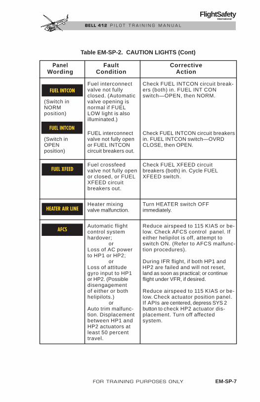
FOR TRAINING PURPOSES ONLY EM-SP-7
FlightSafety International
BELL 412 P I L O T T R A I N I N G M A N U A L
Panel Fault Corrective Wording Condition Action
Fuel interconnect Check FUEL INTCON circuit break-valve not fully ers (both) in. FUEL INT CON closed. (Automatic switch—OPEN, then NORM.
(Switch in valve opening isNORM normal if FUELposition) LOW light is also
illuminated.)
FUEL interconnect Check FUEL INTCON circuit breakers(Switch in valve not fully open in. FUEL INTCON switch—OVRD OPEN or FUEL INTCON CLOSE, then OPEN. position) circuit breakers out.
Fuel crossfeed Check FUEL XFEED circuitvalve not fully open breakers (both) in. Cycle FUELor closed, or FUEL XFEED switch. XFEED circuitbreakers out.
Heater mixing Turn HEATER switch OFFvalve malfunction. immediately.
Automatic flight Reduce airspeed to 115 KIAS or be-control system low. Check AFCS control panel. If hardover; either helipilot is off, attempt to
or switch ON. (Refer to AFCS malfunc-Loss of AC power tion procedures).to HP1 or HP2;
or During IFR flight, if both HP1 and Loss of attitude HP2 are failed and will not reset,gyro input to HP1 land as soon as practical; or continueor HP2. (Possible flight under VFR, if desired.disengagementof either or both Reduce airspeed to 115 KIAS or be-helipilots.) low. Check actuator position panel.
or If APIs are centered, depress SYS 2 Auto trim malfunc- button to check HP2 actuator dis-tion. Displacement placement. Turn off affectedbetween HP1 and system.HP2 actuators atleast 50 percenttravel.
Table EM-SP-2. CAUTION LIGHTS (Cont)
AFCS
FUEL XFEED
HEATER AIR LINE
FUEL INTCON
FUEL INTCON

EM-SP-8 FOR TRAINING PURPOSES ONLY
FlightSafety International
BELL 412 P I L O T T R A I N I N G M A N U A L
Panel Fault Corrective Wording Condition Action
Force trim Check FORCE TRIM switch ON and inoperative. FORCE TRIM circuit breaker in. Dur-
ing IFR flight if system remains in-operative, land as soon as practi-cal; or continue flight under VFR if desired. Pilot may increase cyclic friction to provide additional cyclic stabilization.
Cyclic not centered. Center cyclic.
Rotor rpm at or be- Adust collective pitch and/or RPMlow 95%. INCR—DECR switch as required.
or Refer to ENGINE FUEL CONTROLRotor rpm at or MALFUNCTION procedures.above 105%.
Table EM-SP-2. CAUTION LIGHTS (Cont)
FT OFF
RPM W/AUDIO
RPM W/O AUDIO
CYC CTR

EMERGENCY PROCEDURESENGINE FIRES
Indications• FIRE 1 PULL or FIRE 2 PULL handle illuminated
Engine Fire During StartProcedureAbort the start of an affected engine as follows:
1. Throttle......................................................................................... CLOSED
2. FUEL XFEED Switch ........................................................ OVRD CLOSE
3. BOOST PUMP Switch......................................................................... OFF
4. FUEL Switch........................................................................................ OFF
5. Appropriate FIREPULL Handle..................................................................................... PULL
6. FIRE EXT Switch............................................................................. MAIN
7. If FIRE warning light remains on more than 10 seconds:
FIRE EXT Switch ...................................................................... RESERVE
8. Complete Engine Shutdown
9. Exit Helicopter
Engine Fire During Takeoff or LandingProcedureThe primary concern for the pilot is safety of the passengers and crew. Thedecision whether to begin an approach, or continue the takeoff is based onlanding site availability. Proceed as follows:
1. Airspeed .................................................................... 45 KIAS MINIMUM
2. Collective..................................................................................... REDUCE(ALTITUDE PERMITTING)
3. Appropriate FIREPULL Handle..................................................................................... PULL
FOR TRAINING PURPOSES ONLY EM-SP-9
FlightSafety International
BELL 412 P I L O T T R A I N I N G M A N U A L

4. FIRE EXT Switch............................................................................. MAIN
5. If FIRE warning light remains on more than 10 seconds:
FIRE EXT Switch ...................................................................... RESERVE
6. ENG ............................................................................ SET AT 100% RPM(N2) IF POSSIBLE
7. Land as soon as possible
8. Complete engine shutdown
9. Exit helicopter
Engine Fire in FlightProcedureInitiate emergency descent immediately, if possible. Shut down affected en-gine as follows:
1. Collective .................................................................................... REDUCE(ALTITUDE PERMITTING)
2. Appropriate FIREPULL Handle .................................................................................... PULL
3. Throttle ........................................................................................ CLOSED
4. FIRE EXT Switch ............................................................................ MAIN
5. FUEL XFEED Switch ....................................................... OVRD CLOSE
6. BOOST PUMP Switch ........................................................................ OFF
7. FUEL Switch ....................................................................................... OFF
8. Fuel INTCON Switch ....................................................................... OPEN
9. If FIRE warning light remains on more than 10 seconds:
FIRE EXT Switch ...................................................................... RESERVE
10. ENG (unaffected engine) ............................................ SET AT 100% RPM(N2) IF POSSIBLE
11. Land as soon as possible
EM-SP-10 FOR TRAINING PURPOSES ONLY
FlightSafety International
BELL 412 P I L O T T R A I N I N G M A N U A L

If a landing site is not readily available, proceed as follows:
12. FIRE PULL Handle ................................................................................ IN
Provides fire protection for unaffected engine.
13. GEN Switch (affected engine) ............................................................. OFF
14. NON-ESNTL BUS Switch................................................... AS DESIRED
15. If No. 2 engine was shut down:
BATTERY BUS 2 Switch .................................................................... OFF
BATTERY BUS 1 Switch...................................................................... ON
After landing, proceed as follows:
16. Complete engine shut down
17. Exit helicopter
SMOKE OR FUMES IN CABIN
Indications• Smoke, toxic fumes, etc., in the cabin
Procedure1. VENT BLOWER Switch....................................................................... ON
2. Vents and Windows........................................................................... OPEN
3. If additional ventilation is required:
Airspeed ........................................................................... REDUCE TO 60KIAS OR LESS
Passenger Doors ................................................................................ OPEN
4. If time and altitude permit and the source is suspected to be electrical,attempt to identify and isolate the affected system.
5. Land as soon as possible
FOR TRAINING PURPOSES ONLY EM-SP-11
FlightSafety International
BELL 412 P I L O T T R A I N I N G M A N U A L

BAGGAGE COMPARTMENT FIRE
IndicationBAGGAGE FIRE warning light illuminates
Procedure1. Reduce power to minimum required.
2. Land as soon as possible.
3. Inspect tailboom area for damage.
ENGINE FAILURES
Single Engine FailureENG RPM (N2) of the normally operating engine is allowed to droop to 97%during transition from twin-engine operation to single engine operation.When the best rate-of-climb airspeed (70 KIAS) is obtained, ENG RPM (N2)should be increased to 100% if possible.
Flight can be continued on the remaining engine until a desirable landing siteis available. There are certain combinations of gross weight, altitude, and coldambient temperatures at which a single engine approach will result in the OEItorque limit being exceeded. A run-on landing at 20 to 30 KIAS is recommended.
Run-on landings may result in roll oscillations whileon the ground. If this occurs, lowering collectivefully down or disengaging HP1 and HP2 will stop theoscillations.
Loss of an engine while hovering at high gross weight and extremely cold con-ditions will most likely result in exceeding the OEI torque limit. If an over-torque is observed or suspected, an appropriate log book entry shall be made.Refer to Performance Charts in Section 4 of the RFM.
NOTEIf an engine restart is to be attempted, refer to ENGINERESTART in the Malfunction Procedures section.
Indications• ENG 1 OUT or ENG 2 OUT Warning Light illuminated
• GAS PROD below 53% rpm (N1) and decreasing
CAUTION
EM-SP-12 FOR TRAINING PURPOSES ONLY
FlightSafety International
BELL 412 P I L O T T R A I N I N G M A N U A L

• ENG below 85% rpm (N2) and decreasing
• ITT below 400°C and decreasing
• ENG 1 or ENG 2 OIL PRESSURE, DC GENERATOR, and PARTSEP OFF caution lights illuminated
Procedure
If corrective action is not initiated immediately, rotorrpm could decay excessively.
During cold weather operations, carefully monitortorque of the normal engine when one engine fails oris shut down in flight.
1. Collective..................................................................................... REDUCE
Reduce as required to maintain rotor rpm and power within OEI limits.
2. Airspeed ........................................................................................ 70 KIAS
3. RPM Switch ........................................................................ INCR; SET N2RPM AT 100%(IF POSSIBLE)
4. Throttle (affected engine)............................................................. CLOSED
5. BOOST PUMP Switch(affected engine)................................................................................... OFF
6. FUEL Switch (affected engine)............................................................ OFF
7. FUEL XFEED Switch ........................................................ OVRD CLOSE
8. Fuel INTCON Switch ....................................................................... OPEN
9. GEN Switch (affected engine) ............................................................. OFF
10. NON-ESNTL BUS Switch................................................... AS DESIRED
CAUTION
WARNING
FOR TRAINING PURPOSES ONLY EM-SP-13
FlightSafety International
BELL 412 P I L O T T R A I N I N G M A N U A L

11. If No. 2 engine failed:
BATTERY BUS 2 Switch .................................................................... OFF
BATTERY BUS 1 Switch...................................................................... ON
12. MASTER CAUTION Light ............................................................ RESET
13. Altitude ...................................................................... DESCEND BELOW5,000 FEET HP(IF POSSIBLE)
14. Land as soon as practical
Dual Engine FailureIndications
• ENG 1 OUT and ENG 2 OUT Warning Lights illuminated
• RPM Caution Light illuminated
• Rotor rpm Audio on
• GAS PROD below 53% rpm (N1) and decreasing (both engines)
• ENG below 85% rpm (N2) and decreasing (both engines)
• ITT below 400°C and decreasing (both engines)
• ENG 1 and ENG 2 OIL PRESSURE, DC GENERATOR, and PART SEPOFF Caution Lights illuminated
Procedure
If corrective action is not initiated immediately, rotorrpm could decay excessively.
1. Collective Pitch............................................................................ REDUCE
Establish autorotative glide at 70 to 90 KIAS.
WARNING
EM-SP-14 FOR TRAINING PURPOSES ONLY
FlightSafety International
BELL 412 P I L O T T R A I N I N G M A N U A L

NOTEAirspeed for best angle of glide in autorotation is 90KIAS, and airspeed for minimum rate of descent is70 KIAS. Autorotational rate of descent is a functionof airspeed and rotor rpm and is virtually unaffectedby gross weight and density altitude.
2. Accomplish autorotative landing
If time permits before landing, and a restart will not be attempted, proceedas follows:
3. Throttles (both) ............................................................................ CLOSED
4. FUEL Switches (both).......................................................................... OFF
5. BOOST PUMP Switches (both)........................................................... OFF
6. FUEL TRANS Switches (both) ........................................................... OFF
After landing, complete shutdown.
TAIL ROTOR FAILURESThe key to successful handling of a tail rotor emergency lies in the pilot’s abil-ity to quickly recognize the type of malfunction and to select the properemergency procedure. Following is a discussion of some types of tail rotormalfunctions and their probable effects.
Complete Loss of Tail Rotor ThrustIndicationsThis is a situation involving a break in the drive system, such as a severeddriveshaft, wherein the tail rotor stops turning and delivers no thrust. A fail-ure of this type in a powered flight will result in the nose of the helicopterswinging to the right (left side slip) and usually a roll of the fuselage. Nosedown attitude may also be present. The severity of the initial reaction will beaffected by airspeed, density altitude, gross weight, center of gravity, and powerbeing used.
Loss of T/R Thrust at HoverProcedureClose throttles immediately and make a hovering autorotation landing. Yawingcan be expected on touchdown.
FOR TRAINING PURPOSES ONLY EM-SP-15
FlightSafety International
BELL 412 P I L O T T R A I N I N G M A N U A L

Loss of T/R Thrust in ClimbThe degree of right yaw upon failure will be greater than that experienced inlevel flight due to the higher power and anti-torque settings.
ProcedureClose throttles and lower collective pitch immediately. Establish a glidespeed slightly above normal autorotation approach speed.
If a turn is required to reach a more desirable place to land or to align intothe wind, make it to the right if possible. A turn to the right can be more nearlystreamlined by the use of a little power.
Once aligned for landing, yaw can be controlled in the following manner.
Right Yaw
If the nose yaws right with power off, a pulse of up-collective will producemore friction in the mast thrust bearings, creating a left moment. The greaterthe input of the pulse, the more the response will be.
Do not allow rotor rpm to decay below minimum limits.
Moving the collective upward abruptly increases rotor loading. Do not holdthe collective up, as rotor rpm will decrease lower than desirable. It is essentialthat the collective be returned to the down position for autorotation. This cycleis one pulse. The pulse should be rapid (up and down) but should not be usedat low altitudes.
Left Yaw
If the nose yaws left with the power off, a slight addition of power should ar-rest it. Further increase in power results in more right yaw response.
Landing
Run-on landings may result in roll oscillations whileon the ground. If this occurs, lowering the collectivefully down or disengaging HP1 and HP2 will stop theoscillations.
During the final stages of the approach, a mild flare should be executed andall power to the rotor should be off. Maintain helicopter in a slight flare anduse the collective smoothly to execute a soft, slightly nose-high landing.Landing on the aft portion of the skids will tend to correct side drift. If heli-
CAUTION
WARNING
EM-SP-16 FOR TRAINING PURPOSES ONLY
FlightSafety International
BELL 412 P I L O T T R A I N I N G M A N U A L

copter starts to turn, move cyclic as necessary to follow the turn until heli-copter comes to a complete stop. This technique will, in most cases, result ina run-on type landing.
For zero ground speed landing, the deceleration andthe abrupt use of the collective may cause the nose toyaw left. Do not correct with the throttle. Although ap-plication of throttle will result in yawing to the right,addition of power is a very strong response measureand is too sensitive for the pilot to manage properly.Do not add power at this time. Slight yawing upontouchdown at zero ground speed may be expected.
Loss of T/R Thrust in Level Flight or DescentProcedureClose throttles and reduce the collective pitch immediately. Attain an airspeedslightly above the normal autorotative glide speed.
If altitude permits with airspeed above 60 KIAS, throttle and collective maybe gently applied to determine if some degree of powered flight can be re-sumed. If unacceptable yawing is experienced, re-enter autorotation and con-tinue descent to a landing.
The landing technique is the same as prescribed for the climb condition above.
Loss of Tail Rotor ComponentsThe loss of any tail rotor components will result in a forward center of grav-ity shift. Other than additional nose down pitching, this situation would bequite similar to complete loss of tail rotor thrust, as discussed above.
Tail Rotor Fixed Pitch FailuresIndicationsTail rotor pitch change control failures are characterized either by a lack ofdirectional response when a pedal is pushed or by locked pedals. If pedalscannot be moved with a moderate amount of force, do not attempt to apply amaximum effort, since a more serious malfunction could result.
Fixed Pitch Failure at HoverProcedureDo not close throttles unless a severe right yaw occurs. If pedals lock in anyposition at a hover, landing from a hover can be accomplished with greatersafety under power controlled flight rather than by closing throttles and en-tering autorotation.
CAUTION
FOR TRAINING PURPOSES ONLY EM-SP-17
FlightSafety International
BELL 412 P I L O T T R A I N I N G M A N U A L

Fixed Pitch Failure in FlightIf tail rotor fixed pitch failure occurs during climb (left pedal applied), cruise(approximately neutral pedals), and descent (right pedal applied), a descentand landing can be effected safely by use of power and throttle changes.
Procedure
If the helicopter is in a trimmed condition when the malfunction is discov-ered, engine power and airspeed should be noted and the aircraft flown to asuitable landing area.
Combinations of engine torque, rotor rpm, and airspeed will correct or ag-gravate yaw attitude and these should be adjusted as required to control yawduring landing.
Right Pedal Locked Forward of Neutral
Power should be reduced and ENG RPM (N2) maintained within the greenarc. This will help streamline the helicopter in flight. Right turns are easierthan left turns. Airspeed should be maintained at or above 60 KIAS.
Execute a normal to steep approach, adjusting the power as necessary to min-imize or prevent right yaw. Maintain ENG RPM (N2) and an airspeed of about60 KIAS during the initial part of the approach.
At 60 to 75 feet AGL and when the landing area can be made, start a slow de-celeration to arrive at the intended landing point with about 25 knots indi-cated airspeed.
At 2 to 5 feet AGL, slowly reduce throttle to overcome yaw effect and allowthe helicopter to settle. When aligned with the landing area, allow helicopterto touch down.
Run-on landings may result in roll oscillations whileon the ground. If this occurs, lowering the collectivefully down or disengaging HP1 and HP2 will stop theoscillations.
After ground contact, use the collective and throttle as necessary to maintainalignment with landing strip, and to minimize forward speed. If the helicopterstarts to turn, move the cyclic as necessary to follow the turn until the heli-copter comes to a complete stop.
CAUTION
EM-SP-18 FOR TRAINING PURPOSES ONLY
FlightSafety International
BELL 412 P I L O T T R A I N I N G M A N U A L
Left Pedal Locked Forward of Neutral
Reduce power and maintain ENG RPM (N2) within the green arc. Normal turnscan be safely made under these conditions, although the nose may be displacedto the left. Execute a shallow to normal approach.
On final approach, begin a slow deceleration so as to arrive at a point aboutfour to five feet above the intended touchdown area as effective translationallift is lost.
Apply collective pitch to stop the rate of descent and forward speed, and toalign the helicopter with the intended landing path. Allow helicopter to touchdown at near-zero ground speed, maintaining alignment with the throttle.
Pedals Locked in Neutral
Reduce power and maintain ENG RPM (N2) within the green arc. Normal turnscan be safely made under these conditions.
Execute a normal to steep approach, holding airspeed at 60 KIAS during theinitial part of the approach. Adjust power as necessary to minimize or pre-vent right yaw.
At 50 to 75 feet AGL and when the landing area can be made, start a decel-eration to arrive at the intended landing point with airspeed at 25 KIAS.
At 2 to 5 feet AGL, use throttle slowly as necessary to maintain alignmentwith the landing area and to control yaw; do not allow the helicopter to set-tle until alignment is assured, then touch down.
Run-on landings may result in roll oscillations whileon the ground. If this occurs, lowering the collectivefully down or disengaging HP1 and HP2 will stop theoscillations.
After ground contact, use collective and throttle as necessary to minimizeforward speed and to maintain alignment. Move the cyclic as necessary tofollow the turn until the helicopter has come to a complete stop.
CAUTION
FOR TRAINING PURPOSES ONLY EM-SP-19
FlightSafety International
BELL 412 P I L O T T R A I N I N G M A N U A L

Loss of Pitch Change Control LinkageIndicationsIn this type of failure, the pitch-change mechanism is broken at some pointand the tail rotor will assume a blade angle determined by the aerodynamicand counterbalance forces.
ProcedureThe corrective action procedures are described in Fixed Pitch Failures onthe previous page. The specific procedure to be used depends on the yawchange experienced.
MAIN DRIVESHAFT FAILURE
Failure of the main driveshaft to the transmissionwill result in the complete loss of power to the mainrotor. Although the cockpit indications for a drive-shaft failure are somewhat comparable to a dual en-gine failure, it is imperative that autorotative flightprocedures be established immediately. Failure toreact immediately to the LOW ROTOR RPM audiosignal, caution light and tachometer indication willresult in loss of control.
Indications• Left yaw
• Rapid decrease in ROTOR RPM
• Rapid increase in ENG RPM (N2)
• Illumination of rotor RPM caution light with audio
• Possible increase in noise due to:
• Overspeeding engine turbines
• Overspeeding combining gearbox
• Driveshaft breakage
WARNING
EM-SP-20 FOR TRAINING PURPOSES ONLY
FlightSafety International
BELL 412 P I L O T T R A I N I N G M A N U A L
Procedure1. Collective .......................................................................... AS REQUIRED
(TO ESTABLISHAUTOROTATIVE
DESCENT)
2. Airspeed ...............................................................ESTABLISH AIRSPEEDFOR MINIMUM RATE OF
DESCENT (70 KIAS) ORMAXIMUM GLIDE (90 KIAS)
3. Throttles .................................................................................... CLOSE (IFTIME PERMITS)
4. Controls .................................................................... AS REQUIRED FORAUTOROTATIVE LANDING
MALFUNCTION PROCEDURESENGINE HOT START
IndicationsA hot start is caused by excessive fuel in the combustion chamber and delayedfuel ignition. The result is flames emitting from the tail pipe and/or exces-sive ITT indication. Internal and external damage can result.
ProcedureAbort start of affected engine as follows:
1. Throttle ............................................................................ CLOSED (KEEPSTARTER ENGAGED)
2. FUEL Switch........................................................................................ OFF
3. BOOST PUMP Switch......................................................................... OFF
4. Starter................................................................................ CONTINUE TOENERGIZE UNTIL
ITT DECREASES
5. Complete shutdown
6. Exit helicopter and check for damage
If ITT limits for starting were exceeded, an appropriate entry shall bemade in the helicopter logbook. The entry shall state which limit wasexceeded, the duration of time, the extreme value attained, and anyadditional information essential in determining the maintenance actionrequired. Refer to the Engine Maintenance Manual for inspection
Revision 1 FOR TRAINING PURPOSES ONLY EM-SP-21
FlightSafety International
BELL 412 P I L O T T R A I N I N G M A N U A L

requirements.
ENGINE RESTART IN FLIGHTThe conditions which would warrant an attempt to restart the engine wouldprobably be a flameout, caused by a malfunction of the automatic mode ofthe fuel control unit. The decision to attempt an engine restart during flightis the pilot’s responsibility.
If the cause of engine failure is obviously mechani-cal as evidenced by abnormal sounds, do not attempta restart.
ProcedurePosition the controls of the affected engine to attempt restart as follows:
1. Throttle ........................................................................................ CLOSED
2. BOOST PUMP Switch ......................................................................... ON
3. FUEL XFEED Switch .................................................................... NORM
4. FUEL Switch ........................................................................................ ON
5. GOV Switch .............................................................................. MANUAL
6. GEN Switch ........................................................................................ OFF
OEI performance can be affected during generator-assisted start (with both BATTERY switches on).
7. For nonassisted battery start (if No. 1 engine failed):
BATTERY BUS 2 Switch(normal engine) .................................................................................... OFF
BATTERY BUS 1 Switch(affected engine) .................................................................................... ON
8. START Switch.................................................................................. ENG 1
CAUTION
CAUTION
EM-SP-22 FOR TRAINING PURPOSES ONLY
FlightSafety International
BELL 412 P I L O T T R A I N I N G M A N U A L

Observe starter limitations.
9. Engine Oil Pressure ................................................ INDICATING A RISE
When restarting an engine in manual fuel controlmode, carefully monitor ITT.
10. Throttle ..................................................... OPEN SLOWLY AT 12% GASPROD RPM (N1) UNTIL
ITT BEGINS TO RISE
NOTEDo not open throttle further until ITT and GAS PROD RPM(N1) stabilize.
11. START Switch.......................................................... CENTERED AT 55%GAS PROD RPM (N1)
When operating in manual fuel control mode, makeslow, smooth, coordinated throttle and collective move-ments to avoid compressor stall, overtemp, under-speed/overspeed, and possible drive train damage.
12. Throttle................................................................... INCREASE SLOWLY;ADJUST AS REQUIRED TO
CONTROL TORQUE, ITT,AND GAS PROD RPM (N1)
NOTEIf torque of affected engine is controlled slightly(approximately 4%) below torque of normal engine,rotor rpm will be governed within limits automati-cally by normal engine.
13. GEN Switches (both)............................................................................. ON
14. BATTERY BUS 2 Switch...................................................................... ON
CAUTION
CAUTION
FOR TRAINING PURPOSES ONLY EM-SP-23
FlightSafety International
BELL 412 P I L O T T R A I N I N G M A N U A L

15. Fuel TRANS Switch (affected engine).................................................. ON
16. Fuel INTCON Switch...................................................................... NORM
17. Land as soon as practical.
If restart was unsuccessful, secure the affected engine as prescribed in theSingle Engine Failure procedure.
ENGINE FUEL CONTROL MALFUNCTIONSComponents of each engine fuel control system subject to malfunction arethe manual fuel control unit, the automatic fuel control unit (containing thegas producer turbine governor), the power turbine governor, and the torquecontrol unit. In-flight determination of which component has malfunctionedis virtually impossible and is irrelevant to the required corrective action. Thepilot; therefore, is tasked with interpreting the abnormal indications only sofar as to determine which engine has been affected, and which way, in orderto perform the proper corrective action.
The primary indications of a fuel control failure usually will be a TORQUEsplit and an accompanying increase or decrease in ENG RPM (N2) and ROTORRPM. The indications of TORQUE, GAS PROD RPM (N1), and ITT gagesalone will not distinguish a high side failure from a low side failure. The tripletachometer must be checked for high or low ENG/ROTOR RPM indications.
NOTENormal deviation of ROTOR RPM from the governedsetting may occur when large collective changes aremade, but should not be confused with fuel control fail-ure unless a large steady-state torque split occurs.
The indications of a high side or a low side fuel control failure will vary inaccordance with the specific cause of failure and the total power demand atthe time of failure.
High Side Fuel Control FailureIf there is a low power demand (less than single engine power available) at thetime of high side failure, ROTOR RPM and ENG RPM (N2) of the affected en-gine will increase considerably above the governed value. TORQUE, ITT andGAS PROD RPM (N1) of the affected engine will also increase. As ENG RPM(N2) and ROTOR RPM increase above the governed value, the normal enginewill reduce power to keep itself from overspeeding and will indicate significantlylower TORQUE, ITT and GAS PROD RPM (N1) than the affected engine.
EM-SP-24 FOR TRAINING PURPOSES ONLY
FlightSafety International
BELL 412 P I L O T T R A I N I N G M A N U A L
If there is a high power demand (greater than single-engine power available)at the time of high side failure, ROTOR RPM and ENG RPM (N2) of the af-fected engine will surge initially, along with TORQUE, ITT and GAS PRODRPM (N1). As ENG RPM (N2) and ROTOR RPM increase, the normal enginewill reduce power to keep itself from overspeeding. The affected engine thentries to assume all of the load, which is beyond its capability, due to the highpower demand. ENG RPM (N2) of the affected engine (and ROTOR RPM) willthen decrease and rejoin the ENG RPM (N2) of the normal engine, stabiliz-ing at or slightly above the governed value as the normal engine adjustspower output to share the load.
Indications• High ENG RPM (N2) and rotor rpm, possibly with RPM caution light
• Definite TORQUE split (proportional to power demand)
• High GAS PROD RPM (N1), ITT and TORQUE on affected engine
• Return of ENG RPM (N2) and rotor rpm to governed value (if powerdemand is very high)
Procedure
If corrective action is not initiated immediately, ROTORRPM could overspeed excessively.
1. Collective........................................................ ADJUST AS NECESSARYTO MAINTAIN ROTOR RPM
2. Affected Engine ........................................................................ IDENTIFY
3. Throttle (affected engine) ................................. REDUCE TO MAINTAINTORQUE AT OR SLIGHTLY
BELOW TORQUE OFNORMAL ENGINE
4. Throttle Frictions............................................... TIGHTEN ON NORMALENGINE; REDUCE ON
AFFECTED ENGINE
5. Throttle (affected engine)............................................ REDUCE TO IDLE
6. GOV Switch (affected engine) ................................................... MANUAL
CAUTION
FOR TRAINING PURPOSES ONLY EM-SP-25
FlightSafety International
BELL 412 P I L O T T R A I N I N G M A N U A L

When operating in manual fuel control mode, makeslow, smooth, coordinated throttle and collectivemovements to avoid compressor stall, overtemp, un-derspeed/overspeed, and possible drive train dam-age.
8. Throttle (affected engine) ....................................... INCREASE SLOWLYADJUST AS REQUIRED
Adjust throttle and collective as required to maintain torque of affectedengine slightly below torque of normal engine.
9. MASTER CAUTION Light ............................................................ RESET
10. Land as soon as practical.
Low Side Fuel Control FailureIf there is a low power demand (less than single engine power available) atthe time of low side failure, ROTOR RPM and ENG RPM (N2) of the affectedengine will decrease and stabilize at or slightly below the governed value.TORQUE, ITT and GAS PROD RPM (N1) of the affected engine will also de-crease. As ROTOR RPM decreases, the normal engine will increase TORQUEoutput to assume the load. If power demand is near zero, there may not be asignificant TORQUE split.
If there is a high power demand (greater than single engine power available)at the time of low side failure, ROTOR RPM will decrease along with ENG RPM(N2), TORQUE, ITT, and GAS PROD RPM (N1) of the affected engine. AsROTOR RPM decreases, the normal engine will increase to maximum powerto assume the load, causing significant increases in TORQUE, ITT and GASPROD RPM (N1), while ENG RPM (N2) will remain below the governed value.
Indications• Low ENG RPM (N2) and ROTOR RPM (possibly with RPM caution light
and audio if power demand is in excess of single engine power available)
• TORQUE split (proportional to power demand)
• Low GAS PROD RPM (N1), ITT and TORQUE on affected engine
CAUTION
EM-SP-26 FOR TRAINING PURPOSES ONLY
FlightSafety International
BELL 412 P I L O T T R A I N I N G M A N U A L

Procedure
If corrective action is not initiated immediately, rotorrpm could decay excessively.
1. Collective........................................................ ADJUST AS NECESSARY TO MAINTAIN ROTOR RPM
2. Airspeed ........................................................................................ 65 KIAS
3. Affected Engine ........................................................................ IDENTIFY
4. Throttle Frictions............................................... TIGHTEN ON NORMALENGINE; REDUCE ON
AFFECTED ENGINE
5. Throttle (affected engine)............................................ REDUCE TO IDLE
6. GOV Switch (affected engine) ................................................... MANUAL
When operating in manual fuel control mode, makeslow, smooth, coordinated throttle and collective move-ments to avoid compressor stall, overtemp, under-speed/overspeed, and possible drive train damage.
7. Throttle (affected engine) ....................................... INCREASE SLOWLY
Adjust throttle and collective as required to maintain torque of affectedengine slightly below torque of normal engine.
8. MASTER CAUTION Light ............................................................ RESET
9. Land as soon as practical.
CAUTION
WARNING
FOR TRAINING PURPOSES ONLY EM-SP-27
FlightSafety International
BELL 412 P I L O T T R A I N I N G M A N U A L

Governor Actuator Failure (Full Increase)Indications
• ENG RPM (N2) and rotor rpm increase to approximately 101%
• RPM INCR/DECR switch inoperative
ProcedureIf this failure occurs during takeoff or landing, no immediate corrective ac-tion is necessary to complete either maneuver.
As soon as practical, roll back both throttles to maintain 97 to 100% ENG RPM(N2). Further adjustment of collective and throttles simultaneously will allowfull power at pilot’s discretion.
Land as soon as practical.
Governor Actuator Failure (Full Decrease)Published Flight Manual performance may not be attainable.
ELECTRICAL POWER FAILURES
DC Power FailureIndications
• DC GENERATOR caution light illuminates
• All lighting and avionics on the nonessential buses inoperative
Procedure1. GEN FIELD and GEN
RESET circuit breakers ............................................................ CHECK IN
2. GEN Switch (affected generator)................................. RESET, THEN ON
If a generator remains inoperative proceed as follows:
3. GEN Switch (affected generator)......................................................... OFF
4. MASTER CAUTION light.............................................................. RESET
5. If No. 2 generator failed:
BATTERY BUS 2 Switch .................................................................... OFF
BATTERY BUS 1 Switch...................................................................... ON
EM-SP-28 FOR TRAINING PURPOSES ONLY
FlightSafety International
BELL 412 P I L O T T R A I N I N G M A N U A L

6. NON-ESNTL BUS Switch ........................................................ MANUAL
7. DC AMPS ................................................................................. MONITOR
If load exceeds limit:
NON-ESNTL BUS Switch................................................... AS DESIRED
Switch off unnecessary equipment as required.
If both generators fail and neither will reset, proceed as follows:
Do not select EMERG LOAD at pressure altitudesabove 5,000 feet. Both fuel boost pumps will becomeinoperative, resulting in possible fuel starvation.
8. EMERG LOAD Switch ........................................................ AS DESIRED
NOTEA fully charged battery provides electrical power forapproximately 30 minutes under normal conditions.With EMERG LOAD switch in EMERG LOAD po-sition, the battery provides approximately 90 minutesof electrical power.
9. Land as soon as practical.
AC Power FailureIndications
• INVERTER 1 or 2 caution light illuminates
• Possible loss of power to certain AC instruments (with no INVERTERcaution light)
ProcedureIf either INVERTER caution light illuminates, proceed as follows:
1. AC VOLTS..................................................................................... CHECK
Check to determine that remaining inverter has assumed all AC loads.
2. INV PWR Circuit Breakers .................................................... CHECK IN
CAUTION
FOR TRAINING PURPOSES ONLY EM-SP-29
FlightSafety International
BELL 412 P I L O T T R A I N I N G M A N U A L

3. HP1 or HP2 Button (affected system) ....................................... PRESS TO REENGAGE HELIPILOT
If power is lost only to certain AC instruments, but INVERTER caution lightsremain out, proceed as follows:
1. AC FEEDERS CircuitBreakers (8 each) ...................................................................... CHECK IN
During IFR flight, if both inverters fail, land as soon as practical, or continueflight under VFR, if desired.
HYDRAULIC SYSTEM FAILUREThis helicopter has two independent hydraulic boost systems, both of whichsupply power to the flight control system for the main rotor. The tail rotorcontrol system is powered by system 1 only.
If a hydraulic system failure occurs shortly after the helicopter has been coldsoaked at or below –25°C (–13°F), some resistance may occur when thecyclic is near control position extremes. This resistance can be overcome byincreased pilot effort.
Indications• No. 1 or No. 2 HYDRAULIC caution light illuminated
• Abnormal (low, high, or fluctuating) hydraulic pressure in theaffected system
• Possible high temperature in affected system
• Increased pedal forces (if system 1 failed)
• Increased cyclic forces near control extremes (cold weather only)
ProcedureIf either hydraulic system fails, or if system temperature or pressure exceedslimits, proceed as follows:
Do not extend flight with failed hydraulic system. Thehelicopter is not controllable with both hydraulicsystems inoperative.
WARNING
EM-SP-30 FOR TRAINING PURPOSES ONLY
FlightSafety International
BELL 412 P I L O T T R A I N I N G M A N U A L

During cold weather operation, avoid high rates ofclimb. Make approaches and landings into the wind.Avoid extended hovering and do not hover with thewind coming from the aft left quadrant.
1. Affected System ................................................ IDENTIFY POSITIVELY
2. HYDR SYS Switch(affected system) .................................................................................. OFF
3. MASTER CAUTION Light ............................................................ RESET
4. Land as soon as possible
AUTOMATIC FLIGHT CONTROLS SYSTEMAFCS MALFUNCTIONSThe automatic flight control system can be affected by malfunctions of pilotor copilot attitude gyro, either inverter, or by other electrical malfunctions.Failure of the No. 1 hydraulic system will render yaw SAS inoperative butwill not affect pitch or roll SAS or ATT mode functions. Failure of No. 2 hy-draulic system will not affect AFCS.
If both helipilots are disengaged, the following procedures do not apply.
AFCS Fails to Engage or DisengagesIndications
• AFCS caution light illuminated
• HP1 or HP2 off (button not illuminated)
• Possible erratic API indications on HP1 or HP2
• Possible ATT flag displayed on pilot or copilot attitude indicator
• Possible illumination of INVERTER 1 or 2 caution light
NOTEIf inverter 1 or 2 fails, HP1 or HP2 will disengage,but can be reengaged by pressing the respective but-ton on the AFCS control panel.
WARNING
FOR TRAINING PURPOSES ONLY EM-SP-31
FlightSafety International
BELL 412 P I L O T T R A I N I N G M A N U A L

Procedure1. Airspeed .............................................. REDUCE TO 115 KIAS OR LESS
2. INV 1 and 2 Switches ............................................................................ ON
Check No. 1 and No. 2 INVERTER caution lights extinguished.
3. Pilot and Copilot’s ADIs .......................................... CHECK ATT FLAGSRETRACTED, INDICATORSFUNCTIONING PROPERLY
4. Check the following circuit breakers are in:
Do not attempt to reset any circuit breaker morethan once.
a. INV 1 PWR and INV 2 PWR
b. AC FEEDERS
c. NO. 1 and NO. 2 ESNTL BUS FEEDERS (on main DC)
d. AFCS (No. 1 and No. 2)
e. AFCS 26.5V (No. 1 and No. 2)
f. AFCS 115V (No. 1 and No. 2)
g. PILOT and CPLT ATTD SYS
5. HP1 or HP2 button(affected system) ....................................................................... PRESS TO
REENGAGE
If either helipilot will not reengage, or if abnormal control disturbance oc-curs, proceed as follows:
6. Affected Helipilot ................................................................. DISENGAGE
7. If IFR, land as soon as practical; or continue flight under VFR, if desired.
If both helipilots fail to reengage, proceed as follows:
8. Airspeed................................................................................ AS DESIRED
9. If IFR, land as soon as practical; or continue flight under VFR, if desired.
CAUTION
EM-SP-32 FOR TRAINING PURPOSES ONLY
FlightSafety International
BELL 412 P I L O T T R A I N I N G M A N U A L
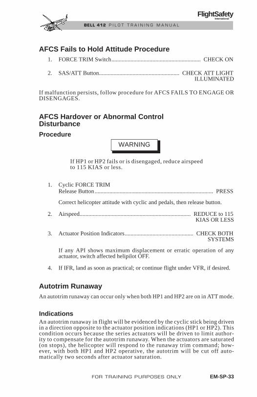
AFCS Fails to Hold Attitude Procedure1. FORCE TRIM Switch............................................................. CHECK ON
2. SAS/ATT Button....................................................... CHECK ATT LIGHTILLUMINATED
If malfunction persists, follow procedure for AFCS FAILS TO ENGAGE ORDISENGAGES.
AFCS Hardover or Abnormal ControlDisturbanceProcedure
If HP1 or HP2 fails or is disengaged, reduce airspeedto 115 KIAS or less.
1. Cyclic FORCE TRIMRelease Button ................................................................................. PRESS
Correct helicopter attitude with cyclic and pedals, then release button.
2. Airspeed............................................................................ REDUCE to 115 KIAS OR LESS
3. Actuator Position Indicators............................................... CHECK BOTHSYSTEMS
If any API shows maximum displacement or erratic operation of anyactuator, switch affected helipilot OFF.
4. If IFR, land as soon as practical; or continue flight under VFR, if desired.
Autotrim RunawayAn autotrim runaway can occur only when both HP1 and HP2 are on in ATT mode.
IndicationsAn autotrim runaway in flight will be evidenced by the cyclic stick being drivenin a direction opposite to the actuator position indications (HP1 or HP2). Thiscondition occurs because the series actuators will be driven to limit author-ity to compensate for the autotrim runaway. When the actuators are saturated(on stops), the helicopter will respond to the runaway trim command; how-ever, with both HP1 and HP2 operative, the autotrim will be cut off auto-matically two seconds after actuator saturation.
WARNING
FOR TRAINING PURPOSES ONLY EM-SP-33
FlightSafety International
BELL 412 P I L O T T R A I N I N G M A N U A L

Procedure1. Cyclic FORCE TRIM
Release Button..................................................... DEPRESS TO CENTERACTUATORS AND RETRIM
TO DESIRED ATTITUDE
2. Airspeed ......................................................................... REDUCE TO 115KIAS OR LESS
NOTEIt is preferable to turn HP2 off to retain yaw stabilization.
3. HP2 or HP1 .......................................................................................... OFF
4. APIs.................................................................................. MONITOR FORPROPER OPERATION
5. If IFR, land as soon as practical; or continue flight under VFR, if desired.
STICK CENTERING INDICATOR FAILURE
Indication• CYC CTR caution lights fail to illuminate when cyclic is displaced
1.5 inches or more from the center position while RPM caution lightis illuminated.
Procedure1. Maintain ROTOR between 97 and 100% rpm for ground operation before
beginning ENGINE SHUTDOWN procedures.
CABIN HEATER MALFUNCTIONA malfunction in the bleed-air heater controls may or may not cause heaterto become inoperative.
EM-SP-34 FOR TRAINING PURPOSES ONLY
FlightSafety International
BELL 412 P I L O T T R A I N I N G M A N U A L

Indications• HEATER AIR LINE caution light illuminates
• Heated air flow does not shut off when thermostat knob is turned tofull cold position
Procedure1. HEATER Switch...................................................... OFF IMMEDIATELY
2. CABIN HTR Circuit Breaker......................................... CHECK; IF OUT,DO NOT RESET
FUEL QUANTITY INDICATIONS MALFUNCTION
Indication• FUEL QTY indication goes to zero from a previously normal condi-
tion. (Possible power failure to the fuel signal conditioner.)
NOTEA power failure to the signal conditioner will disablethe FUEL LOW caution light and alter the FUELTRANS caution indication for affected fuel system.Refer to Table EM-SP-2.
Procedure1. FUEL QTY Circuit Breaker ........................................................RECYCLE
(AFFECTED SIDE)
2. FUEL INTCON Switch ......................................................................OPEN
NOTEAllow sufficient time for fuel levels to equalize.Approximate fuel loads may be obtained by dou-bling remaining fuel quantity indicated.
FOR TRAINING PURPOSES ONLY EM-SP-35
FlightSafety International
BELL 412 P I L O T T R A I N I N G M A N U A L
STATIC PORT OBSTRUCTION
Indication• Erratic readings from the AIRSPEED indicator, VERTICAL SPEED
indicator, and altimeter when operating helicopter in rain with theSTATIC SOURCE switch in PRI position
Procedure1. Windows and vents ...........................................................................CLOSE
2. HEATER Switch ....................................................................................OFF
2. STATIC SOURCE Switch...................................................................ALTN
NOTEThis procedure selects an alternate static source(cabin air) for pilot side instruments only.
COMMUNICATIONSINTERCOM FAILURE
Indication• Weak reception in headset
• No reception in headset
1. Check headset connection.
2. Verify volume and ICS controls set properly.
3. Cycle ICS circuit breaker out and in.
4. For single pilot operations only with Emergency Communications panelinstalled:
a. Plug headset into EMERGENCY COMM jack (above and behind pilotposition).
b. Select desired radio on copilot ICS panel.
c. Key selected radio with EMERGENCY COMM switch (on centerpedestal).
EM-SP-36 FOR TRAINING PURPOSES ONLY Revision 1
FlightSafety International
BELL 412 P I L O T T R A I N I N G M A N U A L
COMMUNICATIONS RADIO FAILURE
Indication• Weak reception in radio
• No reception in radio
Procedure1. Verify proper radio selected.
2. Verify volume properly adjusted.
3. Verify frequency properly set.
4. Cycle appropriate circuit breaker out and in.
Revision 1 FOR TRAINING PURPOSES ONLY EM-SP-37
FlightSafety International
BELL 412 P I L O T T R A I N I N G M A N U A L

LIMITATIONS AND SPECIFICATIONS
CONTENTS
Page
GENERAL OPERATING LIMITATIONS ..................................... LIM-1
Basis of Certification .............................................................. LIM-1
Type of Operation ................................................................... LIM-1
Required Equipment—AFCS ................................................. LIM-1
Required Equipment—IFR..................................................... LIM-1
Optional Equipment................................................................ LIM-2
FLIGHT CREW LIMITATIONS ..................................................... LIM-2
DOORS OPEN OR REMOVED ..................................................... LIM-2
WEIGHT AND CG LIMITATIONS ............................................... LIM-3
Weight Limits ......................................................................... LIM-3
Longitudinal Center-of-Gravity Limits .................................. LIM-3
Lateral Center-of-Gravity Limits............................................ LIM-3
LOADING LIMITATIONS.............................................................. LIM-3
Passenger Loading .................................................................. LIM-3
Internal Cargo Loading........................................................... LIM-5
CLIMB AND DESCENT LIMITATIONS....................................... LIM-5
ALTITUDE LIMITATIONS ............................................................ LIM-5
AMBIENT AIR TEMPERATURE LIMITATIONS ........................ LIM-5
HEIGHT-VELOCITY LIMITATIONS ........................................... LIM-7
MANEUVERING LIMITATIONS .................................................. LIM-7
SLOPE LANDING LIMITATIONS ............................................... LIM-7
ELECTRICAL LIMITATIONS ....................................................... LIM-7
Battery Limitations ................................................................. LIM-7
Generator Limitations............................................................. LIM-9
Engine Starter Limitations...................................................... LIM-9
Ground Power Starts............................................................... LIM-9
HEATER ........................................................................................ LIM-10
Revision 1 FOR TRAINING PURPOSES ONLY LIM-i
FlightSafety International
BELL 412 P I L O T T R A I N I N G M A N U A L

ROTOR BRAKE LIMITATIONS ................................................. LIM-10
FUEL AND OIL LIMITATIONS .................................................. LIM-10
Fuel ....................................................................................... LIM-10
Engine and Combining Gearbox Oil .................................... LIM-10
Transmission, Intermediate and Tail Rotor Gearbox Oil...... LIM-10
HYDRAULIC LIMITATIONS ...................................................... LIM-10
ENGINE RESTART LIMITATIONS ............................................ LIM-11
ENGINE TORQUE LIMITATIONS ............................................. LIM-11
Twin-Engine Operation ........................................................ LIM-11
AIRSPEED LIMITATIONS........................................................... LIM-11
AREAS, DIMENSIONS, WEIGHTS, AND CAPACITIES.......... LIM-16
Airframe ............................................................................... LIM-16
Main Rotor ........................................................................... LIM-16
Tail Rotor.............................................................................. LIM-16
Engine................................................................................... LIM-17
Transmission Rating ............................................................. LIM-17
Weights ................................................................................. LIM-17
Fuel ....................................................................................... LIM-17
Engine Oil............................................................................. LIM-17
Transmission Oil................................................................... LIM-17
Cargo Area............................................................................ LIM-18
Usable Cubage...................................................................... LIM-18
Cargo Door Opening ............................................................ LIM-18
Hoist Penalty Region............................................................ LIM-20
AHRS Alignment ................................................................. LIM-20
LIM-ii FOR TRAINING PURPOSES ONLY Revision 1
FlightSafety International
BELL 412 P I L O T T R A I N I N G M A N U A L

ILLUSTRATIONS
Figure Title Page
LIM-1 Gross Weight Center-of-Gravity Charts ...................... LIM-4LIM-2 Weight-Altitude-Temperature Limitations for Takeoff,
Landing, and In-Ground-Effect Maneuvers................ LIM-6
LIM-3 Height-Velocity Diagram (OEI) ................................... LIM-8LIM-4 Maximum Speed-Sideward and Rearward Flight,
Crosswind and Tailwind at a Hover ........................... LIM-13
LIM-5 Placards and Decals ..................................................... LIM-15
LIM-6 Inspection and Servicing ............................................ LIM-19
LIM-7 Longitudinal/Lateral C.G. Envelope for Hoist Operations .................................. LIM-21
Revision 1 FOR TRAINING PURPOSES ONLY LIM-iii
FlightSafety International
BELL 412 P I L O T T R A I N I N G M A N U A L

Revision 1 FOR TRAINING PURPOSES ONLY LIM-1
FlightSafety International
BELL 412 P I L O T T R A I N I N G M A N U A L
LIMITATIONS AND SPECIFICATIONS
GENERAL OPERATING LIMITATIONSCompliance with the limitations in this section is required by appropriate operating rules.
BASIS OF CERTIFICATIONThis helicopter is certified under FAR Part 29, Category “A” and “B.”
TYPE OF OPERATIONThe basic configured helicopter is approved as a fifteen-place helicopter andis certified for operation under day or night VFR and IFR non-icing conditions.
REQUIRED EQUIPMENT—AFCSAFCS shall be disengaged or operated in SAS mode during prolonged groundoperation, except as required for AFCS check.
Digital AFCS preflight test (level 1 minimum) shall be accomplished priorto first flight of the day or before planned flight into IMC.
REQUIRED EQUIPMENT—IFRIn addition to the basic equipment required for certification, the 412-705-006IFR Kit shall be installed and the following equipment shall be operationalfor IFR flight:
• Both helipilots HP 1 and HP 2 shall be engaged in ATT mode duringIFR flight.
• Heated pitot-static system
• Pilot windshield wiper
• 3-inch standby attitude indicator
• Two VHF communications radios
• Two navigation receivers with auxiliary equipment appropriate to in-tended IFR route of flight
• DME equipment
• ATC transponder
• Marker beacon receiver

• Pilot IVSI
• Force trim
• Roof window blackout curtains
OPTIONAL EQUIPMENTRefer to appropriate Flight Manual supplement(s) for additional limitations,procedures, and performance data with optional equipment installed.
FLIGHT CREW LIMITATIONSThe minimum flight crew consists of one pilot who shall operate the helicopterfrom the right crew seat. Refer to Section 1 of the Manufacturer’s Data forminimum crew weight.
The left crew seat may be used for an additional pilot when the approved dualcontrols and copilot instrument kits are installed.
DOORS OPEN OR REMOVEDHelicopter may be flown with doors open or removed only with Bell StandardInterior (412-705-501) or Bell Deluxe Interior (412-705-500) installed. Flightoperation is approved for following alternative configurations during VFRconditions only:
Symmetrical configurations:
• Both crew doors removed.
• Both sliding doors locked open or removed with both hinged panelsinstalled or removed.
Asymmetrical configurations:
• Cargo doors can be opened or closed asymmetrically, to a locked po-sition, with following restrictions:
• Two way communications between pilot and cabin crew member.
• All crew members and passengers are secured with an approvedrestraint.
NOTEOpening or removing doors shifts helicopter center-of-gravity and reduces VNE. Refer to the RFM,Manufacturer’s Data, and to Airspeed Limitations.
LIM-2 FOR TRAINING PURPOSES ONLY Revision 1
FlightSafety International
BELL 412 P I L O T T R A I N I N G M A N U A L

WEIGHT AND CG LIMITATIONSWEIGHT LIMITSMaximum gross weight for takeoff and landing is 11,600 pounds (5,262kilograms). The SP, HP and EP models, maximum gross weight for take-off and landing is 11,900 pounds (5,398 ki lograms).
Refer to Weight-Altitude-Temperature Limitations chart (Figure LIM-2) formaximum allowable weight for takeoff, landing, and IGE hover operation.
The minimum gross weight for flight is 6,400 pounds (2,903 kilograms).
The minimum combined crew weight at fuselage station 47.0 is 170pounds (77.1 kilograms).
LONGITUDINAL CENTER-OF-GRAVITY LIMITSLongitudinal center-of-gravity limits vary from station 130 to 144, depending ongross weight. Refer to the Gross Weight Center-of-Gravity Chart (Figure LIM-1).
LATERAL CENTER-OF-GRAVITY LIMITSLateral center-of-gravity limitations are 4.5 inches (114.3 millimeters) leftand right of the fuselage centerline for all gross weights.
LOADING LIMITATIONS
NOTERefer to the Weight and Balance section of theManufacturer’s Data for loading tables to be used inweight/CG computations.
PASSENGER LOADINGThe outboard facing seats should not be occupied unless at least four of theforward or aft facing passenger seats are occupied.
The above loading procedure does not apply if cargo or a combination of cargoand passengers are being transported. It shall then be the pilot’s responsibilityto ensure that the helicopter is properly loaded so that the entire flight is conducted within the limits of the Gross Weight Center-of-Gravity Charts(Figure LIM-1).
FOR TRAINING PURPOSES ONLY LIM-3
FlightSafety International
BELL 412 P I L O T T R A I N I N G M A N U A L

LIM-4 FOR TRAINING PURPOSES ONLY
FlightSafety International
BELL 412 P I L O T T R A I N I N G M A N U A L
13,000
12,000
11,000
10,000
9,0008,800
8,000
7,000
6,4006,000
GR
OS
S W
EIG
HT
—L
B
134130
11,900
135.1 141.4
132 144136 138 140 142
AFT LIMITFORWARD LIMIT
MINIMUM WEIGHT130.4
LONGITUDINAL C.G. FUSELAGE STA.—IN.ENGLISH UNITS
Figure LIM-1. Gross Weight Center-of-Gravity Charts
5,800
5,400
5,000
3,992
4,200
4,400
4,600
4,800
5,200
5,600
3,800
3,400
3,600
3,200
3,000
GR
OS
S W
EIG
HT
—K
ILO
GR
AM
S
5,3983,432 3,592
AFT LIMITFORWARD LIMIT
MINIMUM WEIGHT
3,4003,3003,250 3,350 3,650
3,658
3,450 3,500 3,550 3,6002,600
2,800 3,3122,9032,948
LONGITUDINAL C.G.~FUSELAGE STA.—MM.METRIC UNITS

INTERNAL CARGO LOADINGThe maximum allowable deck loading for cargo is 100 pounds per square foot(4.9 kg/100 sq cm). Deck mounted cargo tiedown fittings are provided andhave an airframe structural capacity of 1,250 pounds (567.0 kilograms) ver-tical and 500 pounds (226.8 kilograms) horizontal per fitting. Provisions forinstallation of cargo tiedown fittings are incorporated in the aft cabin bulk-head and transmission support structure and have an airframe structural ca-pacity of 1,250 pounds (567.0 kilograms) at 90 degrees to the bulkhead and500 pounds (226.8 kilograms) in any direction parallel to the bulkhead. Cargoshall be secured by an approved restraint method that will not impede accessto the cargo in the event of an emergency.
A second crewmember is required if cargo consists of flammable materials.Second crewmember shall have access throughout cabin to perform duties offire fighting and ventilating the cabin to remove smoke and toxic fumes inevent of emergency. Approved protective breathing equipment is required foreach crewmember when transporting flammable cargo in cabin.
Baggage compartment has a load limit of 400 pounds (181 kilograms), not toexceed 100 pounds per square foot (4.9 kg/100sq cm).
CLIMB AND DESCENT LIMITATIONSThe maximum IFR rate of climb or descent is 1,000 feet per minute.
The maximum IFR approach slope is 5 degrees.
ALTITUDE LIMITATIONSThe maximum operating pressure altitude is 20,000 feet (6,096 meters).
The maximum density altitude for takeoff, landing, and in-ground-effect ma-neuvers is 14,000 feet (4,267 meters). Refer to the Weight-Altitude-TemperatureLimitations Chart (Figure LIM-2).
Above 15,000 feet (4,572 meters) pressure altitude, restart shall be attemptedin manual fuel control mode only.
Below 15,000 feet (4,572 meters) pressure altitude, restart may be attemptedin either manual or automatic fuel control mode.
NOTERefer to applicable operating rules for high altitudeoxygen requirements.
AMBIENT AIR TEMPERATURE LIMITATIONSThe maximum sea level ambient air temperature for operation is +51.7° C(+125° F) and decreases with pressure altitude at the standard lapse rate of2° C (3.6° F) per 1,000 feet (305 meters) to 20,000 feet (6,096 meters).
Revision 1 FOR TRAINING PURPOSES ONLY LIM-5
FlightSafety International
BELL 412 P I L O T T R A I N I N G M A N U A L

LIM-6 FOR TRAINING PURPOSES ONLY
FlightSafety International
BELL 412 P I L O T T R A I N I N G M A N U A L
WEIGHT—ALTITUDE—TEMPERATURE LIMITATIONSFOR TAKEOFF, LANDING AND IN-GROUND EFFECT MANEUVERS
NOTE: ALLOWABLE GROSS WEIGHTS OBTAINED FROM THIS CHART MAY EXCEED CONTINUOUS HOVER CAPABILITY UNDER CERTAIN AMBIENT CONDITIONS. REFER TO HOVER CEILING CHARTS IN SECTION 4.
14,000 FT.DEN. ALT. LIMIT
10,900 LB
–40 –20 0 20 40 60 9 10 11 12 LB X 1000
4.0 4.5 5.0 5.4 KG X 1000OAT — °CCONDITIONS:
OAT—28° CPA—4,000 FT
MAXIMUMGROSS WEIGHT
LIMIT
MAX OAT
MINOAT
11.9
PR
ES
SU
RE
ALT
ITU
DE
—FT
.
SE
A LE
VE
L
2,00
04,
000
6,00
08,
000
10,0
0012
,000
14,0
00
Figure LIM-2. Weight-Altitude-Temperature Limitations for Takeoff, Landing, and In-Ground-Effect Maneuvers

Minimum ambient temperature for operation at all altitudes with engineoil pressure/temperature indicator 209-070-262-113 installed is –40°C(–40°F).
The minimum ambient temperature for operation at all altitudes with en-gine oil pressure/temperature indicator 209-070-262-109 installed is–34°C (–30°F).
NOTEDuring extremely cold ambient temperatures, idlerpm will be high and the ENGINE OIL pressuremay exceed maximum limits for up to two minutesafter starting.
NOTEEither engine oil pressure/temperature gage shallbe installed in pairs.
HEIGHT-VELOCITY LIMITATIONSThe height-velocity limitations are critical in the event of single enginefailure during takeoff, landing, or other operation near the surface (FigureLIM-3). The AVOID area of the Height-Velocity diagram defines thecombinations of airspeed and height above ground from which a safe sin-gle engine landing on a smooth, level, firm surface cannot be assured.
The Height-Velocity diagram is valid only when the Weight-Altitude-Temperature limitations are not exceeded (Figure LIM-2). The diagramdoes not define the conditions which assure continued flight following anengine failure nor the conditions from which a safe power-off landing canbe made.
MANEUVERING LIMITATIONSAerobatic maneuvers are prohibited.
SLOPE LANDING LIMITATIONSSlope landings are limited to side slopes not to exceed 10 degrees.
Revision 1 FOR TRAINING PURPOSES ONLY LIM-7
FlightSafety International
BELL 412 P I L O T T R A I N I N G M A N U A L

LIM-8 FOR TRAINING PURPOSES ONLY Revision 1
FlightSafety International
BELL 412 P I L O T T R A I N I N G M A N U A L
NOTE HELICOPTER CONFIGURATIONSHALL COMPLY WITH THE WEIGHT-ALTITUDE-TEMPERATURE LIMITS AS PRESENTED IN FIGURE 5-1 FOR HEIGHT-VELOCITY DIAGRAM TO BE VALID.
HEIGHT-VELOCITY DIAGRAMFOR SMOOTH, LEVEL, FIRM SURFACES
INDICATED AIRSPEED—KNOTS
0 10 20 30 40 VNE
60
AND ABOVE
100
110
114.3
120
90
80
70
50
40
30
20
10
0
4.9
140
AND ABOVE
340
360
380
400
300
320
240
120
100
80
60
40
016
20
280
260
375
220
200
180
160
SK
ID H
EIG
HT
AB
OV
E S
UR
VA
CE
—M
ET
ER
S
SK
ID H
EIG
HT
AB
OV
E S
UR
VA
CE
—F
EE
T
Figure LIM-3. Height-Velocity Diagram (OEI)
ELECTRICAL LIMITATIONSBATTERY LIMITATIONSThe maximum battery case temperature is 54.5° C (130° F), as indicatedby illumination of the BATTERY TEMP warning light.
The battery shall not be used for engine start afterillumination of BATTERY TEMP light. The bat-tery shall be removed and serviced in accordancewith manufacturer’s instructions prior to return toservice.
The minimum ambient temperature for battery start when battery andhelicopter have been cold soaked is –25° C (–13° F).
GENERATOR LIMITATIONS• Continuous operation — 0 to 75 amps
• Caution — 75 to 150 amps
NOTEDuring OEI operation electrical loads may haveto be reduced to remain below maximum continu-ous limits.
• Maximum continuous — 150 amps (each)
NOTET h e a m m e t e r n e e d l e m a y d e f l e c t f u l l s c a l e momentarily during generator-assisted start of thesecond engine.
ENGINE STARTER LIMITATIONSStarter energizing times shall be limited as follows:
• 30 seconds ON
• 60 seconds OFF
• 30 seconds ON
• 5 minutes OFF
WARNING
Revision 1 FOR TRAINING PURPOSES ONLY LIM-9
FlightSafety International
BELL 412 P I L O T T R A I N I N G M A N U A L

• 30 seconds ON
• 15 minutes OFF
GROUND POWER STARTS28-VDC ground power units for starting shall be limited to 1,000 amps maximum.
HEATERHeater shall not be operated when OAT is above 21° C (69.8° F).
ROTOR BRAKE LIMITATIONSEngine starts with rotor brake engaged are prohibited. Rotor brake applica-tion is limited to ground operation and shall not be applied until both enginesare shut down and rotor rpm has decreased to 40% NR or below.
FUEL AND OIL LIMITATIONS
NOTERefer to Manufacturer’s Data, Section 4, for lists ofapproved fuels, oils, and vendors.
FUELFuel conforming to ASTM D-1655 Type B, NATO F-40, or MIL-T-5624Grade JP-4 may be used at all ambient temperatures.
Fuel conforming to ASTM D-1655 Type A or A-1, NATO F-44, MIL-T-5624Grade JP-5 NATO F-34, or MIL-T-8 3133, Grade JP-8, limited to ambient tem-perature above –30° C (–22° F).
ENGINE AND COMBINING GEARBOX OIL
Oil conforming to PWA Specification No. 521 Type I and MIL-L-7808 maybe used at all ambient temperatures.
Oil conforming to PWA Specification No. 521 Type II and MIL-L-23699(NATO O-156), or DOD-L-85734 as limited to ambient temperatures above –40° C (–40° F).
TRANSMISSION, INTERMEDIATE AND TAIL ROTORGEARBOX OILOil conforming to DOD-L-85734AS (Turbine Oil 555), MIL-L-23699 (NATOO-156), or MIL-L-7808 may be used at all approved ambient temperatures.
NOTEDOD-L-85734AS or MIL-L-23699 is recommended.
LIM-10 FOR TRAINING PURPOSES ONLY Revision 1
FlightSafety International
BELL 412 P I L O T T R A I N I N G M A N U A L

HYDRAULIC LIMITATIONS
NOTERefer to RFM-Manufacturer’s Data, Section 4 for ap-proved fluids and vendors.
Hydraulic fluid type MIL-H-5606 (NATO H-515) shall be used at all ambi-ent temperatures.
Both hydraulic systems shall be operative prior to takeoff.
The helicopter is not controllable with both hydraulicboost systems inoperative.
ENGINE RESTART LIMITSAbove 15,000 feet (4,572 meters) pressure altitude, restart shall be attemptedin manual fuel control mode only.
Below 15,000 feet (4,572 meters) pressure altitude, restart may be attemptedin either manual or automatic fuel control mode.
ENGINE TORQUE LIMITSTWIN-ENGINE OPERATIONThe maximum allowable engine torque differential is 4% during normal op-eration. Refer to the Transmission Torque Limits.
AIRSPEED LIMITATIONSThe minimum IFR airspeed is 60 KIAS.
Basic VNE is 140 KIAS from sea level to 3,000 feet density altitude at allgross weights. VNE decreases for ambient conditions in accordance withairspeed limitations placard (Figure LIM-5).
The airspeed shall not exceed 105 KIAS (or placard VNE, if less) when op-erating above maximum continuous transmission torque 84% and 81% forSP, HP and EP.
VNE with only one helipilot/autopilot engaged is 115 KIAS (or placarded VNE,if less). If both helipilots/autopilots are disengaged, basic VNE applies.
WARNING
Revision 1 FOR TRAINING PURPOSES ONLY LIM-11
FlightSafety International
BELL 412 P I L O T T R A I N I N G M A N U A L

VNE, for steady state autorotation, is:
• 105 KIAS at or below 10,000 feet (3,048 meters) pressure altitude.
• 80 KIAS above 10,000 feet (3,048 meters) pressure altitude.
VNE with doors open or removed is 60 KIAS with energy attenuating pas-senger seats installed.
VNE with doors symmetrically open or removed is 100 KIAS with BellHelicopter Installed Blanket Interior (412-705-501) or Deluxe Interior(412-705-500).
The maximum allowable airspeed for sideward or rearward flight at or below3,000 feet HD is 35 knots. (See Figure LIM-4 for additional limitations.)
The maximum allowable tailwind or crosswind speeds for hover opera-tions at or below 3,000 feet HD is 35 knots. (See Figure LIM-4 for ad-ditional limitations.)
VNE with cargo doors opened asymmetrically is 80 KIAS.
VNE with cargo doors in transit or in an unlocked position is 60 KIAS.
VNE with doors symmetrically open or removed is 60 KIAS with BellHelicopter installed energy attenuating passenger seats (412-706-002).
NOTEAsymmetric door configuration is not authorizedwith energy attenuating seats installed.
Refer to the Critical Relative Wind Azimuths diagram in Section 4 of the RFM.
LIM-12 FOR TRAINING PURPOSES ONLY Revision 1
FlightSafety International
BELL 412 P I L O T T R A I N I N G M A N U A L

Revision 1 FOR TRAINING PURPOSES ONLY LIM-13
FlightSafety International
BELL 412 P I L O T T R A I N I N G M A N U A L
14 16 262422 3230282018 34 36 38
MAXIMUM ALLOWABLE WINDSPEED—35 KNOTS
14,000
12,000
10,000
8,000
6,000
4,000
2,000
0
DE
NS
ITY
ALT
ITU
DE
—F
EE
T
14,000 FT DENSITY ALTITUDELIMITED FOR IGE MANEUVERS
WIND LIMIT
Figure LIM-4. Maximum Speed-Sideward and Rearward Flight, Crosswind and Tailwind at a Hover (Sheet 1 of 2)

LIM-14 FOR TRAINING PURPOSES ONLY Revision 1
FlightSafety International
BELL 412 P I L O T T R A I N I N G M A N U A L
0°30°
90°95°
180°
270°
0°
45°
90°
105°
180°
270°
SEENOTE
1
SEENOTE
2
OGE
IGE
SEENOTE
2
SEENOTE
1
NOTES:1. PEDAL CRITICAL WIND AZIMUTH—HOVERING WITH THE RELATIVE WIND WITHIN THESE AZIMUTH ANGLES CAN RESULT IN THE FOLLOWING:A. INABILITY TO MAINTAIN HEADING DUE TO LARGE LEFT PEDAL REQUIREMENTS FOR CERTAIN WIND VELOCITIES.B. REDUCTION OF AVAILABLE LEFT PEDAL CONTROL WITH A DIRECTIONAL AFCS HARDOVER.2. LONGITUDINAL CYCLIC CRITICAL WIND AZIMUTH—AFT CYCLIC MAY BE LIMITED WITH LONGITUDINAL AFCS HARDOVER.
Figure LIM-4. Maximum Speed-Sideward and Rearward Flight, Crosswind and Tailwind at a Hover (Sheet 2 of 2)

Revision 1
FO
R T
RA
ININ
G P
UR
PO
SES
ON
LY
LIM
-15
FlightSafety
International
BE
LL 4
12
P
ILO
T T
RA
ININ
G M
AN
UA
L
OAT° C
0 2 4 6 8 10 12 14 16 18 20
137 — — — — — — — — — —
140 134 128 122 — — — — — — —
140 139 133 127 121 115 109 103 97 — —
140 140 140 133 127 121 115 109 103 96 91
140 140 140 140 131 124 118 112 106 100 94
140 140 140 138 133 127 121 115 108 102 96
140 139 134 129 124 120 115 110 106 101 97
134
51.7
40
20
0
–10
–20
–30
–40 129 124 120 116 111 107 102 98 94 90
AUTOROTATION VNE 85 KIAS ABOVE 10,000 FT.
INDICATED VNE KNOTS
PRESSURE ALTITUDE IN FTX11,000
DO NOT OPERATEHEATER ABOVE 21
DEG C OUT AIR TEMP
TWIN & 30 MIN OEL 100 8%2 1/2 MIN OEL 102.4%
BASIC FUEL CAP2148 LBS
WITH AUX FUEL KIT412-706-007
3212 LBS412-706-009
2389 LBS
DO NOT APPLY ROTOR BRAKEABOVE 40% RPM
THIS HELICOPTER MUST BE OPERATEDIN COMPLIANCE WITH THE OPERATING
LIMITATIONS SPECIFIED IN THE FAAAPPROVED ROTORCRAFT FLIGHT MAN
IN ALTN POSITION MAINTAIN INSTRUMENT ACCURACY BYCLOSING WINDOWS AIRVENTS AND TURNING HEATER OFF
Figure LIM-5. Placards and Decals
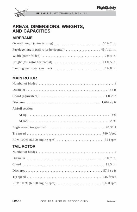
AREAS, DIMENSIONS, WEIGHTS, AND CAPACITIESAIRFRAMEOverall length (rotor turning) . . . . . . . . . . . . . . . . . . . . . . . . . . . . . . 56 ft 2 in.
Fuselage length (tail rotor horizontal) . . . . . . . . . . . . . . . . . . . . . . 45 ft 11 in.
Width (rotor folded) . . . . . . . . . . . . . . . . . . . . . . . . . . . . . . . . . . . . . . . . 9 ft 4 in.
Height (tail rotor horizontal) . . . . . . . . . . . . . . . . . . . . . . . . . . . . . . . 11 ft 5 in.
Landing gear tread (no load) . . . . . . . . . . . . . . . . . . . . . . . . . . . . . . . . 8 ft 8 in.
MAIN ROTORNumber of blades . . . . . . . . . . . . . . . . . . . . . . . . . . . . . . . . . . . . . . . . . . . . . . . . 4
Diameter . . . . . . . . . . . . . . . . . . . . . . . . . . . . . . . . . . . . . . . . . . . . . . . . . . . . . 46 ft
Chord (equivalent) . . . . . . . . . . . . . . . . . . . . . . . . . . . . . . . . . . . . . . . . . 1 ft 2 in
Disc area . . . . . . . . . . . . . . . . . . . . . . . . . . . . . . . . . . . . . . . . . . . . . . . 1,662 sq ft
Airfoil section:
At tip . . . . . . . . . . . . . . . . . . . . . . . . . . . . . . . . . . . . . . . . . . . . . . . . . . . . . 8%
At root . . . . . . . . . . . . . . . . . . . . . . . . . . . . . . . . . . . . . . . . . . . . . . . . . . . 23%
Engine-to-rotor gear ratio . . . . . . . . . . . . . . . . . . . . . . . . . . . . . . . . . . . 20.38:1
Tip speed . . . . . . . . . . . . . . . . . . . . . . . . . . . . . . . . . . . . . . . . . . . . . . . . 780 ft/sec
RPM 100% (6,600 engine rpm) . . . . . . . . . . . . . . . . . . . . . . . . . . . . . . 324 rpm
TAIL ROTORNumber of blades . . . . . . . . . . . . . . . . . . . . . . . . . . . . . . . . . . . . . . . . . . . . . . . . 2
Diameter . . . . . . . . . . . . . . . . . . . . . . . . . . . . . . . . . . . . . . . . . . . . . . . . . 8 ft 7 in.
Chord . . . . . . . . . . . . . . . . . . . . . . . . . . . . . . . . . . . . . . . . . . . . . . . . . . . . . 11.5 in.
Disc area . . . . . . . . . . . . . . . . . . . . . . . . . . . . . . . . . . . . . . . . . . . . . . . . . 57.8 sq ft
Tip speed . . . . . . . . . . . . . . . . . . . . . . . . . . . . . . . . . . . . . . . . . . . . . . . . 745 ft/sec
RPM 100% (6,600 engine rpm) . . . . . . . . . . . . . . . . . . . . . . . . . . . . . 1,660 rpm
LIM-16 FOR TRAINING PURPOSES ONLY Revision 1
FlightSafety International
BELL 412 P I L O T T R A I N I N G M A N U A L
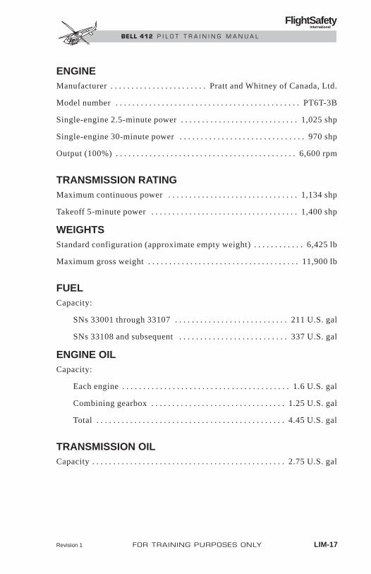
ENGINEManufacturer . . . . . . . . . . . . . . . . . . . . . . . Pratt and Whitney of Canada, Ltd.
Model number . . . . . . . . . . . . . . . . . . . . . . . . . . . . . . . . . . . . . . . . . . . . PT6T-3B
Single-engine 2.5-minute power . . . . . . . . . . . . . . . . . . . . . . . . . . . . 1,025 shp
Single-engine 30-minute power . . . . . . . . . . . . . . . . . . . . . . . . . . . . . . 970 shp
Output (100%) . . . . . . . . . . . . . . . . . . . . . . . . . . . . . . . . . . . . . . . . . . . 6,600 rpm
TRANSMISSION RATINGMaximum continuous power . . . . . . . . . . . . . . . . . . . . . . . . . . . . . . . 1,134 shp
Takeoff 5-minute power . . . . . . . . . . . . . . . . . . . . . . . . . . . . . . . . . . . 1,400 shp
WEIGHTSStandard configuration (approximate empty weight) . . . . . . . . . . . . 6,425 lb
Maximum gross weight . . . . . . . . . . . . . . . . . . . . . . . . . . . . . . . . . . . . 11,900 lb
FUELCapacity:
SNs 33001 through 33107 . . . . . . . . . . . . . . . . . . . . . . . . . . . 211 U.S. gal
SNs 33108 and subsequent . . . . . . . . . . . . . . . . . . . . . . . . . . 337 U.S. gal
ENGINE OILCapacity:
Each engine . . . . . . . . . . . . . . . . . . . . . . . . . . . . . . . . . . . . . . . . 1.6 U.S. gal
Combining gearbox . . . . . . . . . . . . . . . . . . . . . . . . . . . . . . . . 1.25 U.S. gal
Total . . . . . . . . . . . . . . . . . . . . . . . . . . . . . . . . . . . . . . . . . . . . . 4.45 U.S. gal
TRANSMISSION OILCapacity . . . . . . . . . . . . . . . . . . . . . . . . . . . . . . . . . . . . . . . . . . . . . . 2.75 U.S. gal
Revision 1 FOR TRAINING PURPOSES ONLY LIM-17
FlightSafety International
BELL 412 P I L O T T R A I N I N G M A N U A L

CARGO AREA
Length (overall) . . . . . . . . . . . . . . . . . . . . . . . . . . . . . . . . . . . . . . . . . . . 7 ft 8 in.
Width (floor level) . . . . . . . . . . . . . . . . . . . . . . . . . . . . . . . . . . . . . . . . . . . . . 8 ft
Height (maximum) . . . . . . . . . . . . . . . . . . . . . . . . . . . . . . . . . . . . . . . . . 4 ft 4 in.
USABLE CUBAGEMain cargo space . . . . . . . . . . . . . . . . . . . . . . . . . . . . . . . . . . . . . . . . . . 220 cu ft
Left side copilot/passenger seat space . . . . . . . . . . . . . . . . . . . . . . . . . 20 cu ft
Baggage compartment space . . . . . . . . . . . . . . . . . . . . . . . . . . . . . . . . . 28 cu ft
CARGO DOOR OPENINGHeight . . . . . . . . . . . . . . . . . . . . . . . . . . . . . . . . . . . . . . . . . . . . . . . . . . . . 4 ft 7 in.
Width (with hinged panel open) . . . . . . . . . . . . . . . . . . . . . . . . . . . . . . 7 ft 8 in.
Height above ground (approximate) . . . . . . . . . . . . . . . . . . . . . . . . . . 2 ft 6 in.
LIM-18 FOR TRAINING PURPOSES ONLY Revision 1
FlightSafety International
BELL 412 P I L O T T R A I N I N G M A N U A L

Revision 1 FOR TRAINING PURPOSES ONLY LIM-19
FlightSafety International
BELL 412 P I L O T T R A I N I N G M A N U A L
Figure LIM-6. Inspection and Servicing
SYSTEM MATERIAL
FUEL TURBINE FUEL JP-4JP-5JP-8
ENGINE OIL, Lubricating Oil:LEFT AND RIGHT MIL-L-7808POWER SECTIONS, MIL-L-23699AND COMBINING DOD-L-85734 ASGEARBOX
TRANSMISSION OIL Lubricating Oil:MIL-L-7808
MIL-L-23699DOD-L-85734 AS
INTERMEDIATE Lubricating Oil:GEARBOX MIL-L-7808
MIL-L-23699DOD-L-85734 AS
TAIL ROTOR Lubricating Oil:GEARBOX MIL-L-7808
MIL-L-23699DOD-L-85734 AS
HYDRAULIC SYSTEMS Hydraulic Fluid:MIL-L-5606
ROTOR BRAKE Hydraulic Fluid:MIL-L-5606
BATTERY Servicing by qualifiedbattery shop only
ENGINE FIRE EXTINGUISHERS Nitrogen and Freon(PORTABLE EXTINGUISHERS) (Monobromotrifluoromethane)

HOIST PENALTY REGIONPilot shall know C.G. at time of hoist operation to determine if C.G. is withinpenalty region of Hoist C.G. envelope (Figure LIM-7).
Each hoist operation performed is defined as an extension and retraction ofhoist cable while hovering with any weight attached.
Refer to BHT-412-FMS-7 or BHT-412-FMS-26 for Bell Helicopter approvedHoists.
THIS PENALTY IS VALID FOR ALL HOIST IN-STALLATIONS.
OPERATION IN PENALTY REGION AFFECTSAIRWORTHINESS LIMITATIONS OF ROTORCOMPONENTS (REFER TO BHT-412-MM).
LIMITATIONS OF ROTOR COMPONENTS (REFERTO BHT-412-MM).
AHRS ALIGNMENTTo perform in-flight/shipboard AHRS alignment, the following conditions mustbe met:
Pitch . . . . . . . . . . . . . . . . . . . . . . . . . . . . . . . . . . . . . . . . . . .Less than ±10°
Roll . . . . . . . . . . . . . . . . . . . . . . . . . . . . . . . . . . . . . . . . . . . . .Less than ±5°
Yaw Rate . . . . . . . . . . . . . . . . . . . . . . . . . . . . . . . . . . . . . . .Less than 1°/sec
Lateral and . . . . . . . . . . . . . . . . . . . . . . . . . . . . . . . . . . . . . .Less than 0.05gLongitudinal Acceleration
For a minimum of 30 seconds for attitude and heading to become valid.
WARNING
LIM-20 FOR TRAINING PURPOSES ONLY Revision 1
FlightSafety International
BELL 412 P I L O T T R A I N I N G M A N U A L

Revision 1
FO
R T
RA
ININ
G P
UR
PO
SES
ON
LY
LIM
-21
FlightSafety
International
BE
LL 4
12
P
ILO
T T
RA
ININ
G M
AN
UA
L
PENALTYREGION
VNE FOR HOIST OPERATIONS—60 KIAS
LATERAL—INCHES (MILLIMETERS)
FU
SE
LAG
E S
TAT
ION
—IN
CH
ES
(M
ILLI
ME
TE
RS
)
–7(–178)
143(3632)
142(3607)
141(3556)
140(3556)
139(3531)
138(3605)
137(3480)
136(3454)
135(3529)
134(3404)
133(3378)
132(3353)
–6(–152)
–5(–127)
–4(–102)
–3(–76)
–2(–51)
–1(–25)
0(0)
1(25)
2(51)
3(76)
4(102)
5(127)
6(152)
7(178)
Figure LIM-7. Longitudinal/Lateral C.G. Envelope for Hoist Operations

LIMITATIONS AND SPECIFICATIONS412SP
CONTENTSPage
POWERPLANT LIMITATIONS................................................ LIM-SP-1
INSTRUMENT MARKINGS .................................................... LIM-SP-2
FOR TRAINING PURPOSES ONLY LIM-SP-i
FlightSafety International
BELL 412 P I L O T T R A I N I N G M A N U A L

ILLUSTRATIONSFigure Title Page
LIM-SP-1 Instrument Markings ........................................ LIM-SP-2
FOR TRAINING PURPOSES ONLY LIM-SP-iii
FlightSafety International
BELL 412 P I L O T T R A I N I N G M A N U A L

LIMITATIONS AND SPECIFICATIONS412SP
POWERPLANT LIMITATIONS• Pratt and Whitney Aircraft of Canada, Ltd. PT6T-3B
NOTEOperation in 2-1/2 minute or 30-minute OEI range isintended for emergency use only, when one enginebecomes inoperative due to an actual malfunction.
Anytime an engine is operated in an OEI range, an entry shall be made in thehelicopter logbook detailing the extent of operation in excess of twin enginetakeoff power limits. This does not apply to approved ITT limits for starting.
FOR TRAINING PURPOSES ONLY LIM-SP-1
FlightSafety International
BELL 412 P I L O T T R A I N I N G M A N U A L
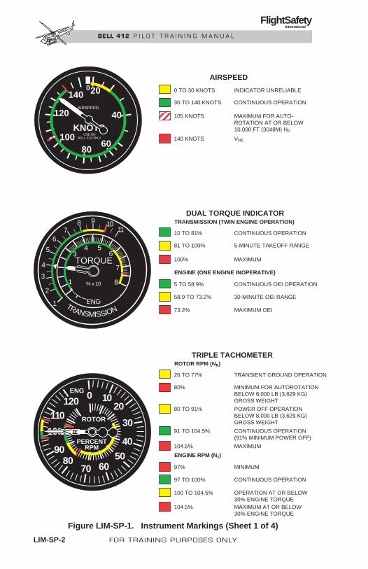
LIM-SP-2 FOR TRAINING PURPOSES ONLY
FlightSafety International
BELL 412 P I L O T T R A I N I N G M A N U A L
Figure LIM-SP-1. Instrument Markings (Sheet 1 of 4)
KNOTS
20
40
6080
100
120
140AIRSPEED
USE ONBELL 412 ONLY
0
TRANSMISSION ENG
TORQUE
43
56
7
81
1
2
3
4
5
67
8 9
% x 10
1011
ENG 0 1020
30
40
506070
8090
100
110120
ROTOR
PERCENTRPM
R
0 TO 30 KNOTS
AIRSPEED
30 TO 140 KNOTS
105 KNOTS
INDICATOR UNRELIABLE
CONTINUOUS OPERATION
MAXIMUM FOR AUTO-ROTATION AT OR BELOW 10,000 FT (3048M) HP
140 KNOTS VNE
10 TO 81%
DUAL TORQUE INDICATORTRANSMISSION (TWIN ENGINE OPERATION)
ENGINE (ONE ENGINE INOPERATIVE)
81 TO 100%
100%
CONTINUOUS OPERATION
5-MINUTE TAKEOFF RANGE
MAXIMUM
5 TO 58.9% CONTINUOUS OEI OPERATION
58.9 TO 73.2% 30-MINUTE OEI RANGE
73.2% MAXIMUM OEI
26 TO 77%
TRIPLE TACHOMETERROTOR RPM (NR)
ENGINE RPM (N2)
80%
80 TO 91%
TRANSIENT GROUND OPERATION
MINIMUM FOR AUTOROTATIONBELOW 8,000 LB (3,629 KG) GROSS WEIGHT
POWER OFF OPERATIONBELOW 8,000 LB (3,629 KG)GROSS WEIGHT
91 TO 104.5% CONTINUOUS OPERATION(91% MINIMUM POWER OFF)
104.5% MAXIMUM
97% MINIMUM
97 TO 100% CONTINUOUS OPERATION
100 TO 104.5% OPERATION AT OR BELOW30% ENGINE TORQUE
104.5% MAXIMUM AT OR BELOW30% ENGINE TORQUE
21

Revision 1 FOR TRAINING PURPOSES ONLY LIM-SP-3
FlightSafety International
BELL 412 P I L O T T R A I N I N G M A N U A L
Figure LIM-SP-1. Instrument Markings (Sheet 2 of 4)
01
23
% X 10RPM
456
78
9 0 12
3
45
678
910
1010
OIL
X 10T P
15
5
0– 5 0
246
8
°C PSI
FUELPSI
3040 50
2010 0
12%
GAS PRODUCER RPM (NI) EITHERGAGE MAY BE INSTALLED IN PAIRS
61%
61 TO 100.8%
MINIMUM FOR OPENING THROTTLEDURING START
FLIGHT IDLE RPM
CONTINUOUS OPERATION
100.8% MAXIMUM FOR TAKEOFF
100.8 TO 102.4% 2 1/2-MINUTE OEI RANGE
102.4% MAXIMUM OEI
15 TO 110°C
TRANSMISSION OIL TEMPERATURE
TRANSMISSION OIL PRESSURE
110°C
CONTINUOUS OPERATION
MAXIMUM
30 PSI MINIMUM FOR FLIGHT IDLE
30 TO 40 PSI FLIGHT IDLE RANGE
40 TO 70 PSI CONTINUOUS OPERATION
70 PSI MAXIMUM
4 PSI
FUEL PRESSURE
4 TO 35 PSI
35 PSI
MINIMUM
CONTINUOUS OPERATION
MAXIMUM
1
1INSTRUMENT PART NUMBER
212-075-037-101
01
23
% X 10RPM
456
78
9 0 12
3
45
678
910
12%
61%
61 TO 101.8%
MINIMUM FOR OPENING THROTTLEDURING START
FLIGHT IDLE RPM
CONTINUOUS OPERATION
101.8% MAXIMUM FOR TAKEOFF
101.8 TO 103.4% 2 1/2-MINUTE OEI RANGE
103.4% MAXIMUM OEI
1
INSTRUMENT PART NUMBER212-075-037-113

LIM-SP-4 FOR TRAINING PURPOSES ONLY
FlightSafety International
BELL 412 P I L O T T R A I N I N G M A N U A L
ENGINE OIL TEMPERATURE0°C MINIMUM
0 TO 115°C CONTINUOUS OPERATION
115°C MAXIMUM
ENGINE OIL PRESSURE40 PSI MINIMUM FOR FLIGHT IDLE
40 TO 80 PSI OPERATION BELOW 79% NI RPM
80 TO 115 PSI CONTINUOUS OPERATION
115 PSI MAXIMUM
0°C
COMBINING GEARBOX OIL TEMPERATURE
0 TO 115°C
MINIMUM
CONTINUOUS OPERATION
115°C MAXIMUM
40 PSI
COMBINING GEARBOX OIL PRESSURE
40 TO 60 PSI
MINIMUM FOR FLIGHT IDLE
OPERATION BELOW 94% NII RPM
60 TO 80 PSI CONTINUOUS OPERATION
80 PSI MAXIMUM
1015
OIL
X 10T P
15
5 °C PSI
0– 5 0
5
10
1010
OIL
X 10T P
15
5
0– 5 0
246
8
°C PSI
Figure LIM-SP-1. Instrument Markings (Sheet 3 of 4)

FOR TRAINING PURPOSES ONLY LIM-SP-5
FlightSafety International
BELL 412 P I L O T T R A I N I N G M A N U A L
AMMETER0 TO 75 AMPS CONTINUOUS OPERATION
75 TO 150 AMPS CAUTION
150 AMPS MAXIMUM
HYDRAULIC OIL TEMPERATURE
HYDRAULIC OIL PRESSURE
88°C MAXIMUM
600 PSI MINIMUM
600 TO 900 PSI CAUTION
900 TO 1100 PSI CONTINUOUS OPERATION
1100 PSI MAXIMUM
300 TO 765°C
INTERTURBINE TEMPERATURE (ITT)
765 TO 810°C
CONTINUOUS OPERATION
5-MINUTE TAKEOFF RANGE
810°C MAXIMUM FOR TAKEOFF
822°C MAXIMUM 30-MINUTE OEI
850°C MAXIMUM 21/2-MINUTE OEI
1090°C MAXIMUM FOR STARTING(2 SECONDS MAXIMUM ABOVE960°C)
AMPS1 2
X1000
1 1
22
3 3
0
9 10
8
7654
3ITT
°C X 100
OE
I
1015
OIL
X 10T P
15
5 °C PSI
0– 5 0
5
10
Figure LIM-SP-1. Instrument Markings (Sheet 4 of 4)

WEIGHT AND BALANCE
CONTENTSPage
GENERAL ....................................................................................... WB-1
CENTER OF GRAVITY (CG)......................................................... WB-1
Empty Weight CG................................................................... WB-1
Gross Weight CG .................................................................... WB-5
CG Limitations ....................................................................... WB-5
Calculating Helicopter CG...................................................... WB-5
Doors Open or Removed......................................................... WB-7
Optional Equipment and Kits ................................................. WB-7
LOADING THE HELICOPTER.................................................... WB-16
Cockpit and Cabin Loading.................................................. WB-16
Baggage Compartment Loading ........................................... WB-19
Fuel Loading......................................................................... WB-30
SAMPLE LOADINGPROBLEM (ENGLISH) ................................................................ WB-31
Required Equipment List...................................................... WB-31
APRIL 1999 FOR TRAINING PURPOSES ONLY WB-i
FlightSafety International
BELL 412 P I L O T T R A I N I N G M A N U A L

ILLUSTRATIONSFigure Title Page
WB-1 CG Reference Datum Lines .............................................. WB-2
WB-2 Helicopter Station Diagram .............................................. WB-4
WB-3 CG Limits ......................................................................... WB-5
WB-4 Actual Weight Record....................................................... WB-7
WB-5 Internal Fuel Tank Station Location ............................... WB-16
TABLESTable Title Page
WB-1 Door Weights and Moments ............................................ WB-9
WB-2 Pilot and Passenger Table of Moments........................... WB-10
WB-3 Internal Cargo Loading Table ......................................... WB-11
WB-4 Baggage Loading Table ................................................. WB-12
WB-5 Fuel Loading Table ......................................................... WB-14
WB-6 Fuel Loading Table—Lateral.......................................... WB-15
WB-7 Required Equipment List................................................ WB-20
APRIL 1999 FOR TRAINING PURPOSES ONLY WB-iii
FlightSafety International
BELL 412 P I L O T T R A I N I N G M A N U A L

WEIGHT AND BALANCE
GENERALProper weight and balance control to ensure that the helicopter CG is withinprescribed limits is essential. Failure to load the helicopter so that it is withinCG limits and then maintain helicopter CG within allowable limits during flightmay result in insufficient control capability and unsafe flight conditions.
Helicopter CG limits, both longitudinal and lateral, are provided in Section1, Limitations, of the RFM. Section 1, Weight and Balance, of the RMD pro-vides all necessary instructions and information for calculating helicopter CG.
Helicopter CG is expressed as a location, in inches or millimeters relative toa reference line, where all of the helicopter’s weight is centered. The Bell 412has two reference points, one for calculating longitudinal CG and one for cal-culating lateral CG.
The longitudinal CG reference line is the reference datum line which is lo-cated approximately 20 inches aft of the helicopter nose. The lateral CG ref-erence line is the centerline of the helicopter (Figure WB-1).
Longitudinal and lateral CG of the helicopter must fall within the allowableCG range listed in the Limitations section of the RFM for all phases of heli-copter flight.
All calculations to determine helicopter CG are based on the weight of itemsloaded on the helicopter and the item’s location in the helicopter in relationto the reference datum lines.
This chapter provides information regarding helicopter center of gravity andcockpit and cabin loading. Loading tables for pilot, passengers, cargo, and fuelare provided. A sample loading problem is provided to aid in flight planning.
APRIL 1999 FOR TRAINING PURPOSES ONLY WB-1
FlightSafety International
BELL 412 P I L O T T R A I N I N G M A N U A L

WB
-2FO
R T
RA
ININ
G P
UR
PO
SES
ON
LY
AP
RIL 1999
FlightSafety
International
BE
LL 4
12
P
ILO
T T
RA
ININ
G M
AN
UA
L
FUSELAGESTATIONS
0 23 166 243
47
22
22 23
34
34
19
1926
FS 138.00 BAGGAGECOMPARTMENT
84 IN.
26
26 26
0
23
8
8
1
2
1
2
87 117 139 156
PILOT SEAT
COPILOT OR PASSENGER SEAT
SEATS
LATERAL LOCATION (INCHES FROM G) OF HELICOPTER
LEGEND
LONGITUDINAL LOCATION (INCHES AFT OF REF DATUM) OF PERSONNEL
EXTERNAL CARGO
CENTERLINE
REFDATUM
Figure WB-1. CG Reference Datum Lines

CENTER OF GRAVITY (CG)EMPTY WEIGHT CGThe empty weight consists of the basic helicopter with required equipment,optional equipment kits, transmission and gearbox oils (not engine oils), hy-draulic fluid, unusable fuel, undrainable engine oil, and fixed ballast. The emptyweight center of gravity shall be adjusted within the limits of the applicableWeight Empty Center of Gravity chart in the Maintenance Manual.
GROSS WEIGHT CGIt shall be the pilot’s responsibility to ensure that the helicopter is properlyloaded so that the entire flight is conducted within the limits of the Gross WeightCenter of Gravity chart in the Limitations section of the Flight Manual. Thegross weight center of gravity may be calculated from the helicopter ActualWeight Record (historical records) and the Loading Tables shown in thischapter or in appropriate Flight Manual Supplements to assure safe loading.
Figure WB-2 presents fuselage station and buttock line data to aid in weightand balance computations.
CG LIMITATIONSLongitudinal and lateral CG range limits are shown in Figure WB-3. Allowablelongitudinal CG range decreases as helicopter gross weight increases. LateralCG range is constant for all gross weights.
APRIL 1999 FOR TRAINING PURPOSES ONLY WB-3
FlightSafety International
BELL 412 P I L O T T R A I N I N G M A N U A L
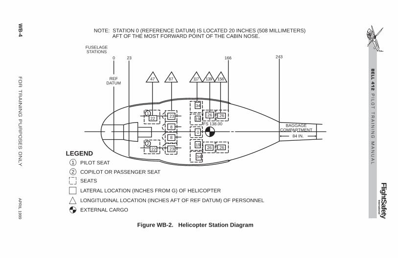
WB
-4FO
R T
RA
ININ
G P
UR
PO
SES
ON
LY
AP
RIL 1999
FlightSafety
International
BE
LL 4
12
P
ILO
T T
RA
ININ
G M
AN
UA
L
Figure WB-2. Helicopter Station Diagram
FUSELAGESTATIONS
NOTE: STATION 0 (REFERENCE DATUM) IS LOCATED 20 INCHES (508 MILLIMETERS) AFT OF THE MOST FORWARD POINT OF THE CABIN NOSE.
REFDATUM
0 23 166 243
47
22
22 23
34
34
19
1926
FS 138.00 BAGGAGECOMPARTMENT
84 IN.
26
26 26
0
23
8
8
1
2
1
2
87 117 139 156
PILOT SEAT
COPILOT OR PASSENGER SEAT
SEATS
LATERAL LOCATION (INCHES FROM G) OF HELICOPTER
LEGEND
LONGITUDINAL LOCATION (INCHES AFT OF REF DATUM) OF PERSONNEL
EXTERNAL CARGO

APRIL 1999 FOR TRAINING PURPOSES ONLY WB-5
FlightSafety International
BELL 412 P I L O T T R A I N I N G M A N U A L
Figure WB-3. CG Limits

CALCULATING HELICOPTER CG
GeneralThe helicopter’s actual CG is calculated by starting with a known helicopterempty weight and moment. The empty weight and moment are originally cal-culated by the manufacturer and are provided in the actual weight record sup-plied with the helicopter when delivered. When installed items are added orremoved from the helicopter, the actual weight record must be refigured toprovide a new empty weight (Figure WB-4).
CG FormulaThe CG of the helicopter, both longitudinal and lateral, is determined by math-ematical calculations using one of the formulas shown below:
Moment = Weight x Arm
Center of Gravity = Total MomentTotal Weight
Moment is an expression of exerted force and is calculated by multiplyingthe weight of an object by its Arm (distance from the reference datum line).For example, a 170-pound pilot sitting in the pilot seat (right seat) has a lon-gitudinal moment of, or exerts a force of, 7,990 inch-pounds (170 x 47) anda lateral moment of +3,740 inch-pounds (170 x 22) (Figure WB-1).
By adding the weights and moments of all fuel, persons, cargo, etc., to theempty weight and moment of the helicopter, the total weight and total mo-ment can be obtained. Then, by dividing the total moment by the total weight,the helicopter CG is easily calculated.
Normally, helicopter longitudinal CG should be calculated for takeoff, land-ing, and the most critical forward CG. Additionally, the Weight and Balancesection of the RMD requires computation of the helicopter’s longitudinal CGfor all cargo/baggage configurations and whenever weight is loaded into thebaggage compartment. Longitudinal CG should also be computed wheneverthe crew doors, hinged panel door, or passenger doors are removed or openfor flight.
Lateral CG should be calculated whenever loading or the use of optionalequipment, such as the rescue hoist, can affect lateral CG.
WB-6 FOR TRAINING PURPOSES ONLY APRIL 1999
FlightSafety International
BELL 412 P I L O T T R A I N I N G M A N U A L
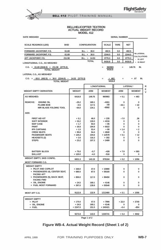
APRIL 1999 FOR TRAINING PURPOSES ONLY WB-7
FlightSafety International
BELL 412 P I L O T T R A I N I N G M A N U A L
DATE WEIGHED SERIAL NUMBER
BELLHELICOPTER TEXTRONACTUAL WEIGHT RECORD
MODEL 412
SCALE READINGS (LBS)
FORWARD JACKPOINT, F.S.
FORWARD JACKPOINT, F.S.
AFT JACKPOINT, F.S.
SKID CONFIGURATION SCALE TARE NET
TOTALLONGITUDINAL C.G., AS WEIGHED
LATERAL C.G., AS WEIGHED*
C.G. = 61.69 (2646.5) + 211.58 (3770.3)
C.G. = –30.0 (402.5) + 30.0 (2244.0) – 14.53 (3770.3)
TOTAL WEIGHT
TOTAL WEIGHT
= 960983 = 149.76 IN.6416.8
= + 463 = + .07 IN.6416.8
*IN LATERAL
CALCULATIONS
– IS LEFT
+ IS RIGHT
61.69
61.69
211.58
B.L. – 30.0
B.L. + 30.0
B.L. ± 14.53
402.5
2244.0
3770.3
6416.8
2244.0
3770.3
6416.8
0.0
0.0
0.0
0.0
402.5
LONGITUDINAL LATERAL*
WEIGHT ARM MOMENT ARM MOMENT
REVWEIGHT EMPTY DERIVATION
AS WEIGHED:
REMOVE: ENGINE OIL PLUMB BOB M/R BLADE FOLDING TOOL
ADD:
FIRST AID KITSOFT INTERIORMAP CASEPAINTIFR CURTAINSCREW SEATSPASSENGER SEATSHEADSETS (2)STEPS
BATTERY BLOCKBALLAST
WEIGHT EMPTY, SKID CONFIG.
MOST FORWARD C.G.
WEIGHT EMPTY + PILOT AND COPILOT + PASSENGERS (4), CENTER SEAT, FACING AFT + PASSENGERS (5), BACK SEAT, FACING FWD + OIL, ENGINE + FUEL MOST FORWARD
WEIGHT EMPTY + PILOT + OIL, ENGINE + FUEL
MOST AFT C.G.
6416.8 149.76 960983 + 0.1 + 463
–25.2–0.5
–64.0
169.1117.5134.1
–4261–59
–8582
0–44.1
0
0+ 22
0
+ 5.1+ 33.2+ 1.7
+ 30.9+ 1.5
+ 90.8+ 120.2
+ 2.6+ 23.2
Page 1 of 2
46.0130.050.0
194.953.454.4
104.6116.3107.3
+ 235+ 4316
+ 85+ 6022
+ 80+ 4940
+ 12578+ 302
+ 2489
–7.0000
+ 1.40
+ 0.100
.36000
+ 20
+ 1200
+ 75.0+ 120.0
–5.7–4.3
–428–516
+ 7.90
+ 5930
6831.3 143.19 978184 + 0.2 + 1056
+ 340.0+ 680.0
+ 850.0
+ 24.5+ 397.0
47.087.0
117.0
169.1139.9
+ 15980+ 59160
+ 99450
+ 4146+ 55540
00
0
00
00
0
00
9122.8 132.9 1212460 + 0.1 + 1056
+ 170.0+ 24.5
+ 2247.0
47.0169.1151.5
+ 7990+ 4146
+ 340421
+ 22.00
–0.4
+ 37400
–854
9272.8 143.5 1330741 + 0.4 + 3942
Figure WB-4. Actual Weight Record (Sheet 1 of 2)
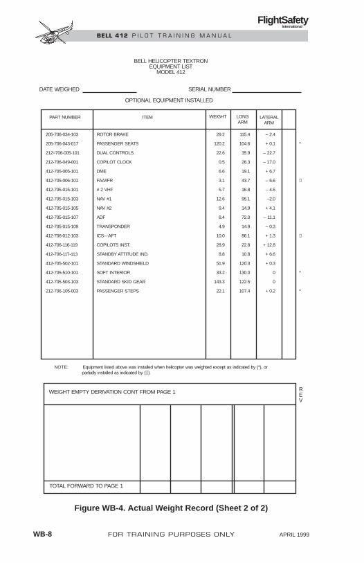
WB-8 FOR TRAINING PURPOSES ONLY APRIL 1999
FlightSafety International
BELL 412 P I L O T T R A I N I N G M A N U A L
BELL HELICOPTER TEXTRONEQUIPMENT LIST
MODEL 412
OPTIONAL EQUIPMENT INSTALLED
PART NUMBER ITEM WEIGHT LONGARM
LATERALARM
DATE WEIGHED SERIAL NUMBER
205-706-034-103
205-706-043-017
212=706-005-101
212-706-049-001
412-705-005-101
412-705-006-101
412-705-015-101
412-705-015-103
412-705-015-105
412-705-015-107
412-705-015-109
412-706-012-103
412-706-116-119
412-706-117-113
412-705-502-101
412-705-510-101
412-705-503-103
212-706-105-003
ROTOR BRAKE
PASSENGER SEATS
DUAL CONTROLS
COPILOT CLOCK
DME
FAA/IFR
# 2 VHF
NAV #1
NAV #2
ADF
TRANSPONDER
ICS—AFT
COPILOTS INST.
STANDBY ATTITUDE IND.
STANDARD WINDSHIELD
SOFT INTERIOR
STANDARD SKID GEAR
PASSENGER STEPS
*
Δ
Δ
*
*
29.2
120.2
22.6
0.5
6.6
3.1
5.7
12.6
9.4
8.4
4.9
10.0
28.9
8.8
51.9
33.2
143.3
22.1
115.4
104.6
35.9
26.3
19.1
43.7
16.8
95.1
14.9
72.0
14.9
86.1
22.8
10.8
120.3
130.0
122.5
107.4
– 2.4
+ 0.1
– 22.7
– 17.0
+ 6.7
– 6.6
– 4.5
–2.0
+ 4.1
– 11.1
– 0.3
+ 1.3
+ 12.8
+ 6.6
+ 0.3
0
0
+ 0.2
NOTE: Equipment listed above was installed when helicopter was weighted except as indicated by (*), or partially installed as indicated by (Δ).
WEIGHT EMPTY DERIVATION CONT FROM PAGE 1
TOTAL FORWARD TO PAGE 1
REV
Figure WB-4. Actual Weight Record (Sheet 2 of 2)

DOORS OPEN OR REMOVEDOpening or removing doors results in center of gravity changes. Door con-figuration shall be symmetrical for both sides of the fuselage. Table WB-1lists weight and moment adjustments which should be made in determiningthe gross weight and CG when a pair of doors are opened or removed.
OPTIONAL EQUIPMENT AND KITSThe installation of optional equipment on the helicopter affects helicopter CGin two ways.
After the installation of optional equipment, the empty weight and momentmust be recomputed and any adjustment made to ensure that the empty weightCG is within allowable limits of the maintenance manuals.
When certain optional equipment is installed, the helicopter’s CG must be cal-culated using the weight and balance information in the appropriate RFM sup-plement. This is particularly important for the external cargo hook, auxiliaryfuel, litter kit, rescue hoist, and any STC kits whose use might affect heli-copter CG.
APRIL 1999 FOR TRAINING PURPOSES ONLY WB-9
FlightSafety International
BELL 412 P I L O T T R A I N I N G M A N U A L
WEIGHT CHANGE ARM MOMENTDOOR CHANGECONFIGURATION (POUNDS) (INCHES) (IN.-LB)
Both crew doors removed –39.0 46.2 –1802Both hinged panels removed –20.4 85.0 –1734Both sliding doors removed –90.4 130.0 –11,752Both sliding doors full open 0 202.0 +6509
Table WB-1. DOOR WEIGHTS AND MOMENTS

LOADING THE HELICOPTEROnce the fuel requirements for the flight have been calculated, the pilotshould determine how the helicopter is loaded.
COCKPIT AND CABIN LOADINGA minimum crew weight of 170 pounds (77.1 kilograms) in the cockpit is re-quired. Except for the two aft passenger seats, crew and passengers may beloaded in any sequence without exceeding the gross weight center of gravitylimits approved for flight.
Refer to Table WB-2 for personnel weights and moments in English.
NOTEThe two aft outboard facing seats should not be oc-cupied unless at least four passengers are seated inthe forward or aft facing seats. The cabin deck cargoloading limit is 100 pounds per square foot (4.9 kg/100 sq cm).
Helicopter center of gravity shall be computed for allcargo baggage/configurations before flight.
WARNING
WB-10 FOR TRAINING PURPOSES ONLY APRIL 1999
FlightSafety International
BELL 412 P I L O T T R A I N I N G M A N U A L
PILOT AND PASSENGER TABLE OF MOMENTS (IN.-LB)
Passenger Passenger PASSENGERPilot and (4-Man Seat (5-Man Seat FACING OUTBOARD
Weight Copilot* Facing Aft) Facing Fwd) Fwd Seat Aft Seat(Pounds) F.S. 47 F.S. 87 F.S. 117 F.S. 139 F.S. 156
100 4700 8700 11700 13900 15600110 5170 9570 12870 15290 17160120 5640 10440 14040 16680 18720130 6110 11310 15210 18070 20280140 6580 12180 16380 19460 21840150 7050 13050 17550 20850 23400160 7520 13920 18720 22240 24960170 7990 14790 19890 23630 26520180 8460 15660 21060 25020 28080190 8930 16530 22230 26410 29640200 9400 17400 23400 27800 31200210 9870 18270 24570 29190 32760220 10340 19140 25740 30580 34320
*Left Forward Seat(TABLE I.D. 910670)
Table WB-2. PILOT AND PASSENGER TABLE OF MOMENTS

Refer to Table WB-3 for internal cargo weight and moment data.
APRIL 1999 FOR TRAINING PURPOSES ONLY WB-11
FlightSafety International
BELL 412 P I L O T T R A I N I N G M A N U A L
INTERNAL CARGO LOADING TABLEMOMENTS IN-LB
WeightPounds F.S. 75.0 F.S. 90.0 F.S. 105.0 F.S. 120.0 F.S. 135.0 F.S. 150.0
50 3750 4500 5250 6000 6750 7500100 7500 9000 10500 12000 13500 15000150 11250 13500 15750 18000 20250 22500200 15000 18000 21000 24000 27000 30000250 18750 22500 26250 30000 33750 37500
300 22500 27000 31500 36000 40500 45000350 26250 31500 36750 42000 47250 52500400 30000 36000 42000 48000 54000 60000450 33750 40500 47250 54000 60750 67500500 37500 45000 52500 60000 67500 75000
550 41250 49500 57750 66000 74250 83500600 45000 54000 63000 72000 81000 90000650 48750 58500 68250 78000 87750 97500700 52500 63000 73500 84000 94500 105000750 56250 67500 78750 90000 101250 112500
800 60000 72000 84000 96000 108000 120000850 63750 76500 89250 102000 114750 127500900 67500 81000 94500 108000 121500 135000950 71250 85500 99750 114000 128250 142500
1000 75000 90000 105000 120000 135000 150000
1050 78750 94500 110250 126000 141750 1575001100 82500 99000 115500 132000 148500 1650001150 86250 103500 120750 138000 155250 1725001200 90000 108000 126000 144000 162000 1800001250 93750 112500 131250 150000 168750 187500
1300 97500 117000 136500 156000 175500 1950001350 101250 121500 141750 162000 182250 2025001400 105000 126000 147000 168000 189000 2100001450 108750 130500 152250 174000 195750 2175001500 112500 135000 157500 180000 202500 225000
(TABLE I.D. 910668)
Table WB-3. INTERNAL CARGO LOADING TABLE

WB-12 FOR TRAINING PURPOSES ONLY APRIL 1999
FlightSafety International
BELL 412 P I L O T T R A I N I N G M A N U A L
BAGGAGE COMPARTMENTLOADING TABLE
NOTE: LOAD BAGGAGE AS FAR FORWARD AS POSSIBLE.
Weight Approximate CG Moment(LB) (Fuselage Sta.—Inches) (IN.-LB)
20 245 490040 247 988060 249 1494080 251 20080
100 253 25300
120 255 30600140 257 35980160 259 41440180 261 46980200 263 52600
220 265 58300240 267 64080260 269 69940280 271 75880300 273 81900
320 275 88000340 277 94180360 279 100440380 281 106780400 283 113200
(TABLE I.D. 910666)
Table WB-4. BAGGAGE LOADING TABLE

APRIL 1999 FOR TRAINING PURPOSES ONLY WB-13
FlightSafety International
BELL 412 P I L O T T R A I N I N G M A N U A L

WB-14 FOR TRAINING PURPOSES ONLY APRIL 1999
FlightSafety International
BELL 412 P I L O T T R A I N I N G M A N U A L
USABLE FUEL LOADING TABLE
Jet B, JP-4 (6.5 Lbs/Gal) Jet A, A-1, JP-5 (6.8 Lbs/Gal)
U.S. Weight CG Moment U.S. Weight CG MomentGal. (Lb) In. In.-Lb. Gal. (Lb) In. In.-Lb.
10 65 139.4 9061 10 68 139.4 947920 130 139.6 18148 20 136 139.6 1898630 195 139.8 27261 30 204 139.8 2851940 260 139.9 36374 40 272 139.9 3805350 325 139.9 45468 50 340 139.9 47566
*58.3 379 139.9 53022 *58.3 397 139.9 5554060 390 141.1 55029 60 408 141.1 5756970 455 146.0 66430 70 476 146.0 6949680 520 149.8 77896 80 544 149.8 8149190 585 152.7 89330 90 612 152.7 93452
100 650 155.0 100750 100 680 155.0 105400110 715 156.8 112112 110 748 156.8 117286120 780 158.3 123474 120 816 158.3 129173130 845 159.7 134947 130 884 159.7 141175140 910 160.9 146419 140.0 952 160.9 153177150 975 156.4 152490 150 1020 156.4 159528160 1040 152.4 158496 160 1088 152.4 165811170 1105 149.0 164645 170 1156 149.1 172244173.1 1125 148.0 166500 173.1 1177 148.0 174196180 1170 149.0 174330 180 1224 149.0 182376190 1235 150.4 185744 190 1292 150.4 194317200 1300 151.6 197080 200 1360 151.6 206176210 1365 152.8 208572 210 1428 152.8 218198220 1430 153.9 220077 220 1496 153.9 230234230 1495 154.7 231277 230 1564 154.7 241951240 1560 155.7 242892 240 1632 155.7 254102
**243.1 1580 155.9 246322 **243.1 1653 155.9 257703250 1625 154.8 251550 250 1700 154.8 263160260 1690 153.2 258908 260- 1768 153.2 270858270 1755 151.8 266409 270 1836 151.3 278705280 1820 150.4 273728 280 1904 150.4 286362290 1885 149.1 281054 290 1972 149.1 294025295.1 1918 148.6 285015 295.1 2007 148.6 298240300 1950 149.9 290550 300 2040 149.0 303960310 2015 149.9 302049 310 2108 149.9 315989320 2080 150.7 313456 320 2176 150.7 327923330 2145 151.4 324753 330 2244 151.4 339742
***330.5 2148 151.5 325422 ***330.5 2247 151.5 340421
*Most critical fuel amount for most forward CG condition.**Most critical fuel amount for most aft CG condition at weight empties up to 6,750 pounds.***Most critical fuel amount for most aft CG condition at weight empties at 6,750 pounds or
greater. Weights given are nominal weights at 15° C.
NOTE
This table is invalid with auxiliary fuel tank(s) installed.
(TABLE I.D. 910664)
Table WB-5. FUEL LOADING TABLE
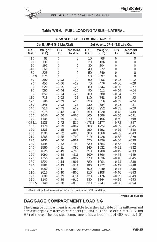
BAGGAGE COMPARTMENT LOADINGThe baggage compartment is accessible from the right side of the tailboom andcontains approximately 25 cubic feet (SP and EP) and 28 cubic feet (107 andHP) of space. The baggage compartment has a load limit of 400 pounds (181
APRIL 1999 FOR TRAINING PURPOSES ONLY WB-15
FlightSafety International
BELL 412 P I L O T T R A I N I N G M A N U A L
USABLE FUEL LOADING TABLE
Jet B, JP-4 (6.5 Lbs/Gal) Jet A, A-1, JP-5 (6.8 Lbs/Gal)
U.S. Weight CG Moment U.S. Weight CG MomentGal. (Lb) In. In.-Lb. Gal. (Lb) In. In.-Lb.
10 65 0 0 10 68 0 020 130 0 0 20 136 0 030 195 0 0 30 204 0 040 260 0 0 40 272 0 050 325 0 0 50 340 0 058.3 379 0 0 58.3 397 0 060 390 –0.03 –12 60 408 –0.03 –1270 455 –0.06 –27 70 476 –0.06 –2980 520 –0.05 –26 80 544 –0.05 –2790 585 –0.04 –23 90 612 –0.04 –24
100 650 –0.04 –26 100 680 –0.04 –27110 715 –0.03 –21 110 748 –0.03 –22120 780 –0.03 –23 120 816 –0.03 –24130 845 –0.03 –25 130 884 –0.03 –27140 910 –0.03 –27 140.0 952 –0.03 –29150 975 –0.43 –419 150 1020 –0.43 –439160 1040 –0.58 –603 160 1088 –0.58 –631170 1105 –0.69 –762 170 1156 –0.69 –798
*173.1 1125 –0.72 –810 *173.1 1177 –0.72 –847180 1170 –0.69 –807 180 1224 –0.69 –845190 1235 –0.65 –803 190 1292 –0.65 –840200 1300 –0.62 –806 200 1360 –0.62 –843210 1365 –0.58 –792 210 1428 –0.58 –828220 1430 –0.56 –801 220 1496 –0.56 –838230 1495 –0.53 –792 230 1564 –0.53 –829240 1560 –0.51 –796 240 1632 –0.51 –832250 1625 –0.49 –796 250 1700 –0.49 –833260 1690 –0.48 –811 260- 1768 –0.48 –849270 1755 –0.46 –807 270 1836 –0.46 –845280 1820 –0.44 –801 280 1904 –0.44 –838290 1885 –0.43 –811 290 1972 –0.43 –848300 1950 –0.41 –800 300 2040 –0.41 –836310 2015 –0.40 –806 310 2108 –0.40 –843320 2080 –0.39 –811 320 2176 –0.39 –849330 2145 –0.38 –815 330 2244 –0.38 –853330.5 2148 –0.38 –816 330.5 2247 –0.38 –854
*Most critical fuel amount for left side most lateral CG condition.
(TABLE I.D. 910662)
Table WB-6. FUEL LOADING TABLE—LATERAL

WB
-16FO
R T
RA
ININ
G P
UR
PO
SES
ON
LY
AP
RIL 1999
FlightSafety
International
BE
LL 4
12
P
ILO
T T
RA
ININ
G M
AN
UA
L
Figure WB-5. Internal Fuel Tank Station Location
FUSELAGESTATIONS
NOTE: STATION 0 (REFERENCE DATUM) IS LOCATED 20 INCHES (508 MILLIMETERS) AFT OF THE MOST FORWARD POINT OF THE CABIN NOSE.
REFDATUM
0
47
BAGGAGECOMPARTMENT
84 IN.
1
2
1
2
84.5
102 127
155
178
FS 138.00
166.5
200 243177.5
PILOT SEAT
COPILOT OR PASSENGER SEAT
FUEL TANKS
LEGEND
LONGITUDINAL LOCATION (INCHES AFT OF REF DATUM) OF PERSONNEL
EXTERNAL CARGO

kilograms), not to exceed 100 pounds per square foot (4.9 kg/100 sq cm). Theseare structural limitations only and do not infer that CG will remain within ap-proved limits. When weight is loaded into the baggage compartment, indis-criminate crew, passenger and fuel loading can no longer be assumed, and thepilot must compute gross weight CG to assure loading within approved limits.
Loading of the baggage compartment should be from front to rear. The loadshall be secured to tiedown fittings if shifting of the load in flight could re-sult in structural damage to the baggage compartment or in gross weight cen-ter of gravity limits being exceeded. The CG shall be computed with the loadin the most adverse position.
Refer to Table WB-4 for baggage weights and moments.
FUEL LOADINGDue to the fuel flow sequencing between the tanks, the fuel loading CG willvary between fuselage station 139.4 and 160.9. The maximum aft CG will occurat approximately 952 pounds for Jet A, A-1, JP-5, and approximately 910pounds for Jet B, JP-4. The maximum forward CG will occur at 397 poundsfor Jet A, A-1, JP-5, and at 379 pounds for Jet B, JP-4. With normal crew andpassenger loading, gross weight CG will remain within limits at any fuel quan-tity. Refer to Tables WB-5 and WB-6 for fuel weights and moments.
Figure WB-5 depicts fuel tank location by station number.
APRIL 1999 FOR TRAINING PURPOSES ONLY WB-17
FlightSafety International
BELL 412 P I L O T T R A I N I N G M A N U A L

WB-18 FOR TRAINING PURPOSES ONLY APRIL 1999
FlightSafety International
BELL 412 P I L O T T R A I N I N G M A N U A L

SAMPLE LOADING PROBLEM (ENGLISH)The helicopter is chartered to transport nine passengers and 180 pounds ofbaggage on a trip that will require approximately 260 U.S. gallons of fuel oneway. The helicopter will be refueled and the 190-pound pilot will returnalone. Determine extreme CG conditions for both flights.
OUTBOUND FLIGHT
LONGITUDINAL LATERAL
WEIGHT CG MOMENT CG MOMENT
Weight Empty 7000 143.0 1001000 +0.2 +1400
+Oil 25 4146 0 0+Pilot 190 8930 +22.0 +4180+Passengers, (5 man seat) 850 99450 0 0+Passengers, (4 man seat) 680 59160 0 0+Baggage 180 46980 0 0
Basic Operating Weight + Payload 8925 136.7 1219666 +0.6 +5580
+Takeoff Fuel (320 U.S. Gallons) 2080 150.7 313456 –0.4 –811
Takeoff Condition 11005 139.3 1533122 +0.4 +4769
Basic Operating Weight + Payload 8925 136.7 1219666 +0.6 +5580
+Critical Forward Fuel(58.3 U.S. Gallons) 379 139.9 53022 0 0
Most Forward Condition 9304 136.8 1272688 +0.6 +5580
Basic Operating Weight + Payload 8925 136.7 1219666 +0.6 +5580
+Landing Fuel (60 U.S. Gallons) 390 141.1 55029 0 0
Landing Condition 9315 136.8 1274695 +0.6 +5580
APRIL 1999 FOR TRAINING PURPOSES ONLY WB-19
FlightSafety International
BELL 412 P I L O T T R A I N I N G M A N U A L

RETURN FLIGHT
LONGITUDINAL LATERAL
WEIGHT CG MOMENT CG MOMENT
Weight Empty 7000 143.0 1001000 +0.2 +1400
WB-20 FOR TRAINING PURPOSES ONLY APRIL 1999
FlightSafety International
BELL 412 P I L O T T R A I N I N G M A N U A L
UNIT LONGITUDINAL LATERAL ARMREQUIRED WEIGHT ARM (–LEFT, +RIGHT)EQUIPMENT LB/kg IN/mm IN/mm
IndicatorsAttitude 7.5/3.4 21.0/533 +17.0/+432Airspeed 1.0/0.5 22.0/559 +12.5/+318Vertical Speed 1.8/0.8 23.2/589 +21.3/+541Altimeter 1.8/0.8 22.0/559 +21.3/+541Triple Tachometer 2.5/1.1 23.2/589 +9.0/+229XMSN Oil Press & Temp 0.7/0.3 25.6/650 +6.0/+152Gearbox Oil Press & Temp 1.0/0.5 25.6/650 +3.0/+76Engine Oil Press & Temp (2) 1.0/0.5 ea. 24.2/615 +4.7/+119Fuel Pressure (2) 0.6/0.3 ea. 24.8/630 +4.7/+119Gas Producer Tachometer (2) 1.0/0.5 ea. 23.0/584 +4.7/+119Turbine Inlet Temperature (2) 0.8/0.4 ea. 23.6/599 +4.7/+119Hydraulic Oil Press & Temp (2) 0.4/0.2 ea. 23.0/584 0/0Dual Torque Pressure 2.6/1.2 23.2/589 +12.5/+318Fuel Quantity 1.0/0.5 23.6/599 +1.3/+33Standby Compass 0.8/0.4 38.0/965 +17.6/+477Horizontal Situation 6.5/2.9 22.5/572 +17.0/+432Clock 0.5/0.2 25.8/655 +26.2/+665Free Air Temperature 0.2/0.1 40.0/1016 +19.0/+483Dual DC Ammeter 1.0/0.5 24.0/610 –1.3/–41Dual AC/DC Voltmeter (2) 1.0/0.5 ea. 24.0/610 0/0Fire Warning—
Engine No. 1 0.4/0.2 24.0/610 –1.7/–43Engine No. 2 0.4/0.2 24.0/610 +4.7/+119Baggage Compartment 0.3/0.1 22.0/559 –1.8/–46
Low Fuel WRN—Master Master 6.5/2.9 24.8/630 –2.5/–64Caution PanelStarter-Generator, L.H. 30.0/13.6 159.0/4039 –8.0/–203Starter-Generator, R.H. 30.0/13.6 159.0/4039 +18.0/+457Battery 74.5/33.8 –6.0/–152 +8.0/+203Starter Toggle Switch 0.4/0.2 38.0/965 +10.0/+254Fuel Igniter Switch (2) 0.2/0.1 ea. 33.0/838 +3.0/+76Anticollision Light, Upper 1.5/0.7 169.0/4293 0/0Anticollision Light, Lower 1.5/0.7 65.4/1661 0/0Landing Light 8.0/3.6 85.3/2167 –4.8/–104Searchlight 5.5/2.5 50.0/1270 +17.6/+447Position Lights—
Forward Lower (2) 0.3/0.1 ea. 66.0/1676 0/0Forward Upper (2) 0.3/0.1 ea. 109.0/2769 0/0Aft (2) 0.3/0.1 ea. 432.0/10973 0/0
Circuit-Breaker Panels (2) 9.7/4.4 ea. 55.4/1407 0/0Nonessential Bus Switch 0.1/NEG. 41.3/1049 +3.7/+94
Table WB-7. REQUIRED EQUIPMENT LIST

+Oil 25 4146 0 0+Pilot 190 8930 +22.0 +4180
Basic Operating Weight 7215 140.6 1014076 +0.8 +5580
+Takeoff Fuel (320 U.S. Gallons) 2080 150.7 313456 –0.4 –811
Takeoff Condition 9295 142.8 1327532 +0.5 +4769
Basic Operating Weight 7215 140.6 1014076 +0.8 +5580
+Critical Forward Fuel(58.3 U.S. Gallons) 379 139.9 53022 0 0
Most Forward Condition 7594 140.5 1067098 +0.8 +5580
Basic Operating Weight 7215 140.6 1014076 +0.8 +5580
+Landing Fuel (60 U.S. Gallons) 390 141.1 55029 0 0
Landing Condition 7605 140.6 1069105 +0.7 +5580
APRIL 1999 FOR TRAINING PURPOSES ONLY WB-21
FlightSafety International
BELL 412 P I L O T T R A I N I N G M A N U A L
UNIT LONGITUDINAL LATERAL ARMREQUIRED WEIGHT ARM (–LEFT, +RIGHT)EQUIPMENT LB/kg IN/mm IN/mm
Essential BusR.H. Ovhd Cont Pnl 3.2/1.5 41.3/1049 +3.7/+94L.H. Ovhd Cont Pnl 2.6/1.2 41.3/1049 –3.7/–94
Low Fuel Wrn XMTR (2) 0.1/NEG. 143.0/3632 0/0ea.
VHF No. 1 Radio—Transceiver and Mount 3.8/1.7 10.1/257 –7.8/–198Control 0.5/0.2 39.0/991 –4.3/–109Antenna 1.0/0.5 211.1/5362 0/0
Windshield Wiper—Blade and Arm (2) 1.6/0.7 ea. 34.5/876 0/0Motor (2) 4.2/1.9 ea. 41.0/1041 0/0
Fire Extinguisher, Hand Type, L.H. 3.0/1.4 67.8/1722 –35.0/–889Fire Extinguisher, Hand Type, R.H. 3.0/1.4 53.5/1359 +34.5/+876
Flight Manual 1.7/0.8 –/– –/–Seat with Restraint—Pilot 45.4/20.6 54.4/1382 +22.0/+559Seat with Restraint—Copilot 45.4/20.6 54.4/1382 –22.0/–559Map and Data Case` 1.9/0.9 59.0/1499 0/0First Aid Kit 5.1/2.3 45.5/1156 –7.2/–183
Table WB-7. REQUIRED EQUIPMENT LIST (CONT)

PERFORMANCECONTENTS
Page
INTRODUCTION .......................................................................... PER-1
GENERAL...................................................................................... PER-1
LIMITATIONS................................................................................ PER-1
General .................................................................................. PER-1
Basis of Certification............................................................. PER-2
Type of Operation.................................................................. PER-2
Required Equipment.............................................................. PER-2
Optional Equipment .............................................................. PER-2
Flight Crew............................................................................ PER-3
Doors Opened or Removed ................................................... PER-3
Weight/CG............................................................................. PER-3
Airspeed ................................................................................ PER-6
Altitude.................................................................................. PER-8
Ambient Air Temperature ..................................................... PER-8
Height-Velocity ..................................................................... PER-8
Maneuvering.......................................................................... PER-8
Slope Landing ..................................................................... PER-10
Systems ............................................................................... PER-10
Bell 412EP Limitations ....................................................... PER-10
HELICOPTER PERFORMANCE ............................................... PER-12
General ................................................................................ PER-12
Hover Ceiling—In GroundEffect (IGE)......................................................................... PER-12
Hover Ceiling—Out of GroundEffect (OGE) ....................................................................... PER-14
Bell 412EP Performance ..................................................... PER-14
PERFORMANCE CHARTS ........................................................ PER-18
POWER ASSURANCE CHECK ................................................. PER-18
DENSITY ALTITUDE CHART .................................................. PER-24
FOR TRAINING PURPOSES ONLY PER-i
FlightSafety International
BELL 412 P I L O T T R A I N I N G M A N U A L

CRITICAL RELATIVE WINDAZIMUTHS CHART ................................................................... PER-26
HOVER CEILING CHARTS ....................................................... PER-28
Hover Ceiling—IGE ........................................................... PER-28
Hover Ceiling—OGE.......................................................... PER-32
TAKEOFF DISTANCE CHARTS................................................ PER-37
TWIN-ENGINERATE-OF-CLIMB CHARTS ....................................................... PER-45
SINGLE-ENGINERATE-OF-CLIMB CHARTS ....................................................... PER-53
LANDING DISTANCE................................................................ PER-57
AIRSPEED CALIBRATION CHART ......................................... PER-58
MOST EFFICIENT AIRSPEED .................................................. PER-59
NOISE LEVELS........................................................................... PER-60
Certification......................................................................... PER-60
Supplemental Information................................................... PER-60
CATEGORY A OPERATIONS.................................................... PER-61
PER-ii FOR TRAINING PURPOSES ONLY
FlightSafety International
BELL 412 P I L O T T R A I N I N G M A N U A L

FOR TRAINING PURPOSES ONLY PER-iii
FlightSafety International
BELL 412 P I L O T T R A I N I N G M A N U A L
ILLUSTRATIONSFigure Title Page
PER-1 Weight-Altitude-TemperatureLimitations Chart ...................................................... PER-4
PER-2 Gross WeightCenter-of-Gravity Chart ............................................ PER-5
PER-3 Airspeed Limitations Placard .................................... PER-6
PER-4 Maximum Speed—Sideward andRearward Flight, Crosswindand Tailwind at a Hover ............................................ PER-7
PER-5 Height–Velocity Diagram .......................................... PER-9
PER-6 PT6T-3D ITT Limitations........................................ PER-10
PER-7 PT6T-3D N1 Limitations.......................................... PER-11
PER-8 PT6T-3D Engine OilSystem Limitations .................................................. PER-11
PER-9 Hover Ceiling IGE—Bell 412SP .................................................... PER-13
PER-10 Hover CeilingIGE—Bell 412HP .................................................... PER-13
PER-11 Hover CeilingOGE—Bell 412SP .................................................. PER-15
PER-12 Hover CeilingOGE—Bell 412HP .................................................. PER-15
PER-13 Hover CeilingOGE Comparison .................................................... PER-17
PER-14 Single-EngineRate-of-Climb Comparison...................................... PER-19
PER-15 Power AssuranceCheck for PT6T-3BEngine—Hover ........................................................ PER-20
PER-16 Power AssuranceCheck for PT6T-3BEngine—In-Flight .................................................... PER-21
PER-17 Power AssuranceCheck for PT6T-3DEngine—Hover ........................................................ PER-22
PER-18 Power AssuranceCheck for PT6T-3DEngine—In-Flight .................................................... PER-23

PER-19 Density Altitude Chart ............................................ PER-25
PER-20 Critical RelativeWind Azimuths ........................................................ PER-27
PER-21 Hover Ceiling—InGround Effect .......................................................... PER-29
PER-22 Hover Ceiling—Out ofGround Effect .......................................................... PER-33
PER-23 Takeoff Distance Chart.. ........................................ PER-38
PER-24 Twin-EngineRate-of-Climb Chart .............................................. PER-46
PER-25 Single-EngineRate-of-Climb Chart. .............................................. PER-54
PER-26 Single-Engine LandingDistance Chart. ........................................................ PER-57
PER-27 Airspeed Calibration Chart .................................... PER-58
PER-28 Power Required (Typical) ........................................ PER-59
PER-29 Category A Operations ............................................ PER-62
PER-30 Fuel Flow vs Airspeed Charts.................................. PER-64
PER-iv FOR TRAINING PURPOSES ONLY
FlightSafety International
BELL 412 P I L O T T R A I N I N G M A N U A L

PERFORMANCE
INTRODUCTIONThis chapter introduces the methods the operator may use to determine theperformance capabilities of the Bell 412 for a particular operation. Some ofthe pertinent limitations from the Rotorcraft Flight Manual (RFM) have beenincluded for training purposes.
The performance data presented herein are derived from the engine manu-facturer’s specification power for the engine less installation losses. Thesedata are applicable to the basic helicopter without any optional equipment whichwould appreciably affect lift, drag, or power available.
GENERALIt is helpful to remember that the performance data in Section 4 of the RFMis informational data while the limitations in Section I of the RFM requiremandatory compliance. The weight of the loaded helicopter and the result-ing center of gravity is the variable that the pilot can control most effectivelyin order to achieve the performance required for the operation. The weightand balance of the 412 is a primary factor in many of the requirements of theLimitations section of the RFM.
Helicopter performance charts are provided in Section 4 of the RFM, andweight and balance loading data is in Section 1 of the (412 AND SP) and Section5 (HP and EP) of theRotorcraft Manufacturer's Data (RMD).
Data supplied in these sections reflects information needed to obtain optimumhelicopter performance while, at the same time, minimizing wear and tear onindividual parts to ensure maximum component life and safety.
Performance charts provide the pilot with information on how the helicopterperforms, provided applicable limitations are followed and the engines areproviding proper power. Since engine performance is somewhat variable,helicopter performance charts are based on the engine manufacturer's spec-ification engine power.
The following text covers limitations and performance charts separately.Sample performance charts are provided for reference. The pilot should referto the latest revisions of the RFM and RMD for the most current information.
LIMITATIONSGENERALThe limitations section of the RFM is specifically approved by the FederalAviation Administration, and it is the pilot in command's responsibility to en-sure compliance with all limitations in the RFM.
FOR TRAINING PURPOSES ONLY PER-1
FlightSafety International
BELL 412 P I L O T T R A I N I N G M A N U A L

Limitations for manufacturer-approved optional equipment are provided inSection 5 (412 and SP) Appendix A (HP and EP Optional EquipmentSupplements), of the RFM. If optional equipment is installed in the helicopter,the limitations of the appropriate supplement may supersede the limitationsof Section I of the RFM.
The pilot should refer to Section 1 of the RFM during the following discussion.
BASIS OF CERTIFICATIONThe Bell 412 is certified under FAR Part 29 for Transport Category Helicoptersand is approved for both Category A and Category B operations. For CategoryA operations data see Section 6 (412 and SP), and Appendix A (HP and EPOptional Equipment Supplements) of the RMD.
TYPE OF OPERATIONThe helicopter is certified for flight in nonicing conditions, both day and nightVFR/ IFR.
REQUIRED EQUIPMENTA list of required equipment is provided in the RFM Weight and Balance sec-tion. These items are required for both VFR and IFR certified Bell 412s.Additional required equipment for IFR operation is provided in Section 1,Limitations, of the RFM.
OPTIONAL EQUIPMENTOptional equipment supplements are provided in Section 5 (412 and SP) ofthe RFM, Appendix A (HP andEP Optional Equipment Supplements) of theRMD and are listed by a different number for each piece of equipment cov-ered. Limitations, performance data, and weight and balance information foroptional equipment approved under a Supplemental Type Certificate (STC)are provided by the holder of the STC.
If optional equipment is installed, the associated limitations, procedures(both normal and malfunction), performance data, and weight and balance in-formation, provided in the supplements, have the same FAA status as that sup-plied in the RFM.
Some optional equipment may prohibit operation of the helicopter under cer-tain circumstances.
For example, installation of the Nightsun searchlight or the Loudhailer pro-hibits IFR operations. The pilot should consult the appropriate RFM supple-ment for specific limitations and restrictions.
PER-2 FOR TRAINING PURPOSES ONLY Revision 1
FlightSafety International
BELL 412 P I L O T T R A I N I N G M A N U A L
FLIGHT CREWThe Bell 412 is certified for single-pilot operation for both VFR and IFR.An additional crewmember is required when internal cargo includesflammable materials.
DOORS OPENED OR REMOVEDThe helicopter may be operated with the doors opened or removed symmet-rically during VFR operations. CG and airspeed restrictions apply. Limitationsare addressed on page LIM-2.
WEIGHT/CG
GeneralNumerous weight and CG limitations apply; the pilot should refer to theRFM for additional information.
Maximum gross weight for takeoff and landing is 11,900 pounds unless oth-erwise restricted by the weight-altitude-temperature chart or other factors.
Weight-Altitude-Temperature Limitations ChartThe weight-altitude-temperature limitations for takeoff, landing, and in-ground-effect (IGE) maneuvers chart, commonly called the W-A-T chart, isused to determine the maximum allowable weight for takeoffs, landings, andIGE hovering operation. The W-A-T chart is a limitations chart as opposedto a performance chart. The gross weights determined from the W-A-T chartmay exceed continuous IGE and OGE hover capability under certain ambi-ent conditions (Figure PER-1).
The W-A-T chart is a good general reference chart for flight planning and canbe used to determine helicopter gross weight limits for the most critical por-tion of a flight. Once the limiting gross weight is determined, the takeoff grossweight can be calculated.
W-A-T chart gross weight limitations should be computed for both initial take-off and the hottest and highest conditions expected for IGE hovering.Conservative rather than optimistic OAT and PA values should be used to avoidless than expected performance.
If the helicopter must be hovered extensively IGE or hovered OGE to performthe flight mission, the pilot should refer to the Hover Ceiling IGE or OGEcharts in the Performance section of the RFM to determine helicopter grossweight. A detailed discussion of the Hover Ceiling Charts is provided laterin this chapter.
FOR TRAINING PURPOSES ONLY PER-3
FlightSafety International
BELL 412 P I L O T T R A I N I N G M A N U A L
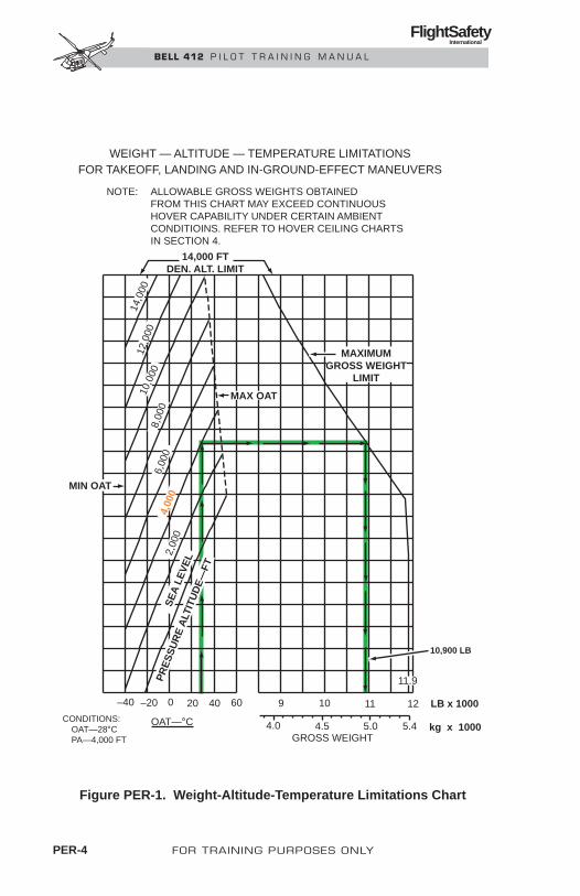
PER-4 FOR TRAINING PURPOSES ONLY
FlightSafety International
BELL 412 P I L O T T R A I N I N G M A N U A L
GROSS WEIGHT4.0 4.5 5.0 5.4
–40 –20 0 20 40 60 9 10 11 12
OAT—°CCONDITIONS: OAT—28°C PA—4,000 FT
14,0
00
2,00
04,
000
6,00
08,
000
10,0
0012
,000
SE
A L
EV
EL
PR
ES
SU
RE
ALT
ITU
DE
—FT
LB x 1000
kg x 1000
10,900 LB
11.9
MIN OAT
MAX OAT
14,000 FTDEN. ALT. LIMIT
MAXIMUMGROSS WEIGHT
LIMIT
NOTE: ALLOWABLE GROSS WEIGHTS OBTAINED FROM THIS CHART MAY EXCEED CONTINUOUS HOVER CAPABILITY UNDER CERTAIN AMBIENT CONDITIOINS. REFER TO HOVER CEILING CHARTS IN SECTION 4.
WEIGHT — ALTITUDE — TEMPERATURE LIMITATIONSFOR TAKEOFF, LANDING AND IN-GROUND-EFFECT MANEUVERS
Figure PER-1. Weight-Altitude-Temperature Limitations Chart

Additional Weight LimitsMinimum gross weight for flight is 6,400 pounds.
Minimum combined weight in the crew seats is 170 pounds.
Center-of-Gravity LimitsCG range is from station 130 to 144, depending on gross weight (Figure PER-2).
Lateral CG limits are 4.5 inches left and right of the fuselage centerline.
Loading LimitationsPassenger Loading—Outboard facing seats should not be occupied until atleast four of the forward or aft facing seats are occupied.
Internal Cargo Loading—Maximum deck loading is 100 pounds per squarefoot. Cargo tiedown limitations are provided in the RFM.
FOR TRAINING PURPOSES ONLY PER-5
FlightSafety International
BELL 412 P I L O T T R A I N I N G M A N U A L
13000
6000
6400
7000
8000
88009000
10000
11000
12000
GR
OS
S W
EIG
HT
135.1 141.4
130.4 MINIMUM WEIGHT
130 132 134 136 138 140 142 144
11900
AFT LIMITFORWARD LIMIT
Figure PER-2. Gross Weight Center-of-Gravity Chart

AIRSPEEDAll airspeed limitations are based on installation of the airspeed indicator,part number 412-075-009-105.
Minimum IFR airspeed is 60 KIAS.
VNE is 140 KIAS from sea level up to 3,000 feet density altitude for all grossweights. VNE decreases with density altitude in accordance with the cockpitplacard (Figure PER-3).
An airspeed of 105 KIAS maximum with torque above 81% exists for maxi-mum continuous power.
VNE with only one helipilot/autopilot engaged is 115 KIAS.
Basic VNE applies with both helipilots/autopilots disengaged.
Steady-state autorotation VNE below 10,000 feet PA is 105 KIAS.
Steady-state autorotation VNE above 10,000 feet PA is 80 KIAS.
VNE with doors open or removed is 60 KIAS.
Maximum speed for sideward or rearward flight is 35 knots at or below 3,000feet density altitude.
PER-6 FOR TRAINING PURPOSES ONLY Revision 1
FlightSafety International
BELL 412 P I L O T T R A I N I N G M A N U A L
PRESSURE ALTITUDE IN FT X 100
INDICATED VNE KNOTS
OAT°C
51.7
40
20
0
–10
–40
–30
–20
137
140
140
140
140
140
140
140
140
140
140
140
140
140
134
124
124
134
124
134
139
139
138
129
129
128
133
133
133
120
121
131
121
121
120
122
127
127
127
116
115
115
118
115
115
111
110
112
109
109
107 102
102
101
100
103
103
106
106
108
97
97
98 94
96
96
90
91
94
—
— —
— — — — — — —
— ———— ————
AUTOROTATION VNE 80 KIAS ABOVE 10,000 FT.
0 2018161412108642
Figure PER-3. Airspeed Limitations Placard

Maximum crosswind or tailwind is 35 knots at or below 3,000 feet densityaltitude. For additional limitations, refer to Figure PER-4 and the CriticalRelative Wind Azimuths diagram in Section 4 of the RFM.
Climb/Descent LimitationsMaximum IFR rate of climb or descent is 1,000 feet per minute.
Maximum IFR approach slope is 5°.
FOR TRAINING PURPOSES ONLY PER-7
FlightSafety International
BELL 412 P I L O T T R A I N I N G M A N U A L
0°
45°
90°
105°
180°
270°
LONGITUDINAL CYCLICCRITICAL WIND AZIMUTH—AFT CYCLIC MAY BELIMITED WITH LONGITUDINALAFCS HARDOVER.
PEDAL CRITICAL WIND AZIMUTH—LEFT PEDAL MAY BE LIMITEDWITH DIRECTIONAL AFCSHARDOVER. REFER TO SECTION 3OF THE RFM.
14,000 FT DENSITY ALTITUDELIMITED FOR IGE MANEUVERS
14,000
6,000
4,000
2,000
8,000
10,000
12,000
0
14 16 18 20 22 24 26 28 30 32 34 36 38
MAXIMUM ALLOWABLE WINDSPEED—35 KNOTS
DE
NS
ITY
ALT
ITU
DE
—F
EE
T
WIND LIMIT
Figure PER-4. Maximum Speed—Sideward and Rearward Flight,Crosswind and Tailwind at a Hover

ALTITUDEMaximum operating altitude is 20,000 feet pressure altitude.
Maximum DA for takeoff, landing, and IGE maneuvers is 14,000 feet.
AMBIENT AIR TEMPERATUREMaximum temperature is 125° F (51.7° C).
Minimum temperature is –40° F (–40° C).
HEIGHT–VELOCITYThe height–velocity diagram indicates airspeed/altitude areas (shaded) fromwhich a safe single-engine landing to a smooth level surface cannot be as-sured. The height–velocity diagram is only valid when weight-altitude-tem-perature limitations are not exceeded (Figure PER-5).
NOTEWhen the aircraft is in an approved configuration ofnine passengers or less, the Height–Velocity Diagramis removed as a limitation, provided that takeoffsand landings are limited to a maximum of 9,000 feetdensity altitude or less (see BHT-412-FMS-3 1).
The height-velocity limitations are critical in the event of single engine fail-ure during takeoff, landing, or other operation near the surface (Figure PER-1). The AVOID area of the height velocity diagram defines the combinationsof airspeed and height above ground from which a safe single engine land-ing on a smooth, level, firm surface cannot be assured.
The height-velocity diagram is valid only when the weight-altitude-temper-ature limitations are not exceeded (Figure PER-5). The diagram does not de-fine the conditions which assure continued flight following an engine failurenor the conditions from which a safe power off landing can be made.
MANEUVERINGAerobatic maneuvers are prohibited.
PER-8 FOR TRAINING PURPOSES ONLY Revision 1
FlightSafety International
BELL 412 P I L O T T R A I N I N G M A N U A L

FOR TRAINING PURPOSES ONLY PER-9
FlightSafety International
BELL 412 P I L O T T R A I N I N G M A N U A L
400AND ABOVE
120AND ABOVE
0
40
20
60
80
100
120
140
160
180
200
220
240
260
280
300
320
340
360
380375
16
0 VNE40302010
114.3110
100
90
80
70
60
50
40
30
20
10
4.9
0
HEIGHT—VELOCITY DIAGRAM
INDICATED AIRSPEED—KNOTS
SK
ID H
EIG
HT
AB
OV
E S
UR
FAC
E—
FE
ET
SK
ID H
EIG
HT
AB
OV
E S
UR
FAC
E—
ME
TE
RS
FOR SMOOTH, LEVEL, FIRM SURFACES
NOTE: HELICOPTER CONFIGURATION SHALL COM- PLY WITH THE WEIGHT ALTITUDE. TEMPER- ATURE LIMITS AS PRESENTED IN FIGURE PER-1 FOR HEIGHT-VELOCITY DIAGRAM TO BE VALID.
AVOID
Figure PER-5. Height–Velocity Diagram

SLOPE LANDINGSlope landings are limited to a maximum 10° side slope.
If the slope landing kit 412-704-012 is installed on the 412HP and EP, addi-tional limitations of the supplement apply.
SYSTEMSSection 1 of the RFM also provides limitations for operation of the electri-cal, powerplant, transmission, rotor, fuel, oil, and hydraulic systems. The pilotshould review these limitations and the instrument panel gage markings ap-plicable to the specific system.
BELL 412EP LIMITATIONSBell 412EP limitations that have changed from previous model 412s affectonly those relating to the PT6T-3D engines. These new limits are for ITT, N1and engine oil temperature. Please refer to Figures PER-6 through PER-8.
PER-10 FOR TRAINING PURPOSES ONLY
FlightSafety International
BELL 412 P I L O T T R A I N I N G M A N U A L
ITT GAGE 212-075-067-115
MAXIMUM CONTINUOUS TWIN–ENGINE OPERATION ITT .................................. 810°MAXIMUM CONTINUOUS ONE ENGINE INOPERATIVE ITT .................................. 820°MAXIMUM 2.5-MINUTE ONE ENGINE INOPERATIVE ITT ...................................... 925°MAXIMUM STARTING ITT (2 SEC MAX ABOVE 960°).......................................... 1,090°
Figure PER-6. PT6T-3D ITT Limitations

NOTEThe above limits also apply to the C-BOX Oil System.
FOR TRAINING PURPOSES ONLY PER-11
FlightSafety International
BELL 412 P I L O T T R A I N I N G M A N U A L
MAXIMUM CONTINUOUS TWIN–ENGINE OPERATION N1 .............................. 103.1%MAXIMUM CONTINUOUS ONE ENGINE INOPERATIVE N1 .............................. 103.7%MAXIMUM 2.5-MINUTE ONE ENGINE INOPERATIVE N1 .................................. 109.2%
Figure PER-7. PT6T-3D N1 Limitations
OIL TEMPERATURE – CONTINUOUS OPERATION.................................. 0° TO 115° CMAXIMUM OIL TEMPERATURE FOR MIL-L-7808 ................................................ 115° CMAXIMUM OIL TEMPERATURE FOR MIL-L-23699 .............................................. 120° CMAXIMUM OIL TEMPERATURE FOR DOD-L-85734 ............................................ 120° C
Figure PER-8. PT6T-3D Engine Oil System Limitations

HELICOPTER PERFORMANCEGENERALThe improvement in Bell 412 HP performance can best be defined by com-parison with 412 SP performance. The following provides comparisons undercertain atmospheric conditions and is for example only. The pilot must referto Section 4, Performance, of the RFM for specific performance data.
HOVER CEILING—IN GROUND EFFECT (IGE)By referring to Figures PER-9 and PER-10 and using ambient conditions ofOAT = +10°C and an HP (pressure altitude) of 3,000 feet. We determine thatmaximum gross weight (MGW) is 11,800 pounds for the 412SP and 11,900for the 412HP (Example A)—not too impressive an improvement. But re-member, at this point we are still at the structural limit for the 412HP whilethe 412SP is at a performance limit.
If we were using the same chart and OAT of +10°C to determine the highestaltitude at which we could hover each aircraft at MGW of 11,900 pounds,we would find that the 412 could be hovered at 1,400 feet HP while the 412HP could be hovered at 3,500 feet HP, almost 2,000 feet higher (Example B).
Perhaps a better comparison would be the following: the pilot has to hover andtakeoff an 11,900-pound 412 from an oil platform at sea level on a +30°C day(Example C). Even though the charts indicate that this is within the capabilityof both 412SP and 412HP helicopters, the 412SP will be hovering using sig-nificantly less than 100% transmission torque while the 412HP will be hover-ing using significantly less than 100% mast torque. It is evident that the 412HPwill have a significant margin of power and takeoff will be much easier.
PER-12 FOR TRAINING PURPOSES ONLY
FlightSafety International
BELL 412 P I L O T T R A I N I N G M A N U A L

FO
R T
RA
ININ
G P
UR
PO
SES
ON
LY
PE
R-13
FlightSafety
International
BE
LL 4
12
P
ILO
T T
RA
ININ
G M
AN
UA
L
14,000 FT. DEN. ALT. LIMIT
BELL 412—SPHOVER CEILING
IN GROUND EFFECT
POWER: SEE NOTE BELOWENG – 100% RPM (N2)GENERATOR 150 AMPS (EA)
SKID HEIGHT 4 FEETHEATER ON OR OFF
– 40° TO 52°C
–40 –30 –20 –10 0
OAT — °C
10 20 30 40 50 60 8 9 10 11 12
5.45.04.5GROSS WEIGHT
4.03.5
LB X 1000
KG X 1000
MAX OAT
MAX OAT
50 °C
MAX OAT HEATER ON (21°C)
11.9
MAXIMUM GROSS WEIGHT LIMIT
14,0
00
12,0
00
10,0
00
8,00
0 6,
000
4,00
0 2,
000
-2,0
00
SEA LEVEL
PRESSURE ALT
ITUDFE
—
EXAMPLE A
EXAMPLE B
EXAMPLE C
1400
FT
3000
FT
NOTE: THESE IGE HOVERCEILING ARE BASED ON DENSITY ALTITUDE LIMITS FOR TAKEOFF AND LANDING. THIS HELICOPTER CAN BE HOVERED IGE AT THE INDICATED GROSS WEIGHTS WITH LESS THAN TAKEOFF POWER FOR TEMPERATURES BELOW 48°C.
Figure PER-9. Hover Ceiling IGE—Bell 412SP
BELL 412—HP/EPHOVER CEILING
IN GROUND EFFECT
POWER: SEE NOTE BELOWENGINE RPM 100% (N2)GENERATOR 150 AMPS (EA)
SKID HEIGHT 4 FEETHEATER ON OR OFF
– 40° TO 52°C
14,000 FT. DEN. ALT. LIMIT
MA
X O
AT
NOTE: THESE IGE HOVERCEILING ARE BASED ON DENSITY ALTITUDE LIMITS FOR TAKEOFF AND LANDING. THIS HELICOPTER CAN BE HOVERED IGE AT THE INDICATED GROSS WEIGHTS WITH LESS THAN TAKEOFF POWER AT ALL
MAXIMUM GROSS WEIGHT LIMIT
11.9
MA
X O
AT
HE
AT
ER
ON
(21°C)
–40 –30 –20 –10 0
OAT — °C
10 20 30 40 50 60 8 9 10 11 12
5.45.04.5GROSS WEIGHT
4.03.5
LB X 1000
KG X 1000
14,0
00
12,0
00
10,0
00
8,00
0 6,
000
4,00
0
-2,0
00
-4,0
00 SEA L
EVEL
PRESSURE ALT
ITUDFE
— EXAMPLE B
EXAMPLE A
EXAMPLE C
3500
FT
3000
FT
2,00
0
Figure PER-10. Hover Ceiling IGE—Bell 412HP

HOVER CEILING—OUT OF GROUND EFFECT (OGE)By referring to Figures PER-11 and PER-12, we have a comparison of the twohelicopters for hovering OGE at takeoff power.
The MGW for a 412SP to hover OGE on a standard day (+15) at sea level is11,500 pounds while the 412HP can easily hover at 11,900 pounds MGW(Example A).
A +30°C day at sea level would further limit the 412SP to a hovering MGWof 11,400 pounds while the 412SP can still be hovered at 11,900 pounds andhave a small power reserve available (Example B).
BELL 412EP PERFORMANCEWhile new PT6T-3D engines have been installed in the Bell 412EP, overallhelicopter normal operation (twin engine) performance remains essentiallyunchanged from the Bell 412HP. This is primarily because of airframe limi-tations rather than engine limitations.
The first indication of changed or improved engine performance appears sig-nificantly in the Power Assurance Check charts, where N1 rpm was previouslyone of the two limiting factors in determining single-engine power assurance(ITT being the other). In the PT6T-3D power assurance check charts, the vari-able N1 rpm limitation (previously dependent upon torque, pressure altitudeand temperature for the PT6T-3B/E) is noticeably absent and has been replacedby a single blanket statement in the procedures and conditions above thechart, stating: “Do not exceed 810° ITT, 103.1% N1 rpm, or 73.2% Torque.”For the PT6T-3D engines, ITT is now the primary limiting factor. Refer toPower Assurance section presented later in this chapter.
NOTEComparison figures are for Bell 412HP vs Bell 412EP.
The only published normal performance area that indicates increased per-formance as a result of increased engine capability is Hover Ceiling—Out-of-Ground Effect which is discussed below.
Single-engine (OEI) performance also shows some improvement. The pub-lished area where improved engine performance is most evident is SingleEngine Rate of Climb which is also discussed below.
PER-14 FOR TRAINING PURPOSES ONLY
FlightSafety International
BELL 412 P I L O T T R A I N I N G M A N U A L
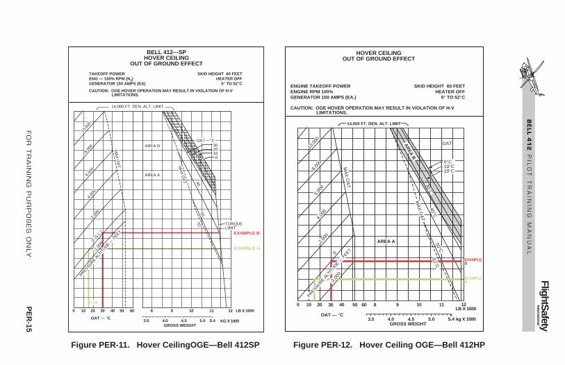
FO
R T
RA
ININ
G P
UR
PO
SES
ON
LY
PE
R-15
FlightSafety
International
BE
LL 4
12
P
ILO
T T
RA
ININ
G M
AN
UA
L
BELL 412—SPHOVER CEILING
OUT OF GROUND EFFECT
TAKEOFF POWERENG — 100% RPM (N2) GENERATOR 150 AMPS (EA)
CAUTION: OGE HOVER OPERATION MAY RESULT IN VIOLATION OF H-V LIMITATIONS.
SKID HEIGHT 60 FEETHEATER OFF
0° TO 52°C
14,000 FT. DEN. ALT. LIMIT
0
OAT — °C
10 20 30 40 50 60 8 9 10 11 12
5.45.04.5GROSS WEIGHT
4.03.5
LB X 1000
KG X 1000
MA
X O
AT M
AX
OA
T
5250
40
AREA A
TORQUELIMIT
AREA BOAT °C
302010 0
10,0
00
8,00
0 6,
000
4,00
0 2,
000
0 (S
.L.)
-1,0
00
PRESSURE ALT
ITUDE —
FEET EXAMPLE B
EXAMBLE A
+15
Figure PER-11. Hover CeilingOGE—Bell 412SP
14,000 FT. DEN. ALT. LIMIT
0
OAT — °C
10 20 30 40 50 60 8 9 10 11 12
5.45.04.5GROSS WEIGHT
4.03.5
LB X 1000
kg X 1000
HOVER CEILINGOUT OF GROUND EFFECT
ENGINE TAKEOFF POWERENGINE RPM 100%GENERATOR 150 AMPS (EA.)
CAUTION: OGE HOVER OPERATION MAY RESULT IN VIOLATION OF H-V LIMITATIONS.
SKID HEIGHT 60 FEETHEATER OFF
0° TO 52°C
MA
X O
AT
10,0
00
8,00
0 6,
000
4,00
0 2,
000
0
-2,0
00
PRESSURE ALT
ITUDE —
FEET
AREA A
AR
EA B
MA
X O
AT
52°C50°C
40°C30°C
OAT
EXAMPLEB
EXAMPLE A
0°C10°C20°C
Figure PER-12. Hover Ceiling OGE—Bell 412HP

Pending a further revision in the manufacturer’s Rotorcraft Flight Manual,no other published performance improvements are evident. However, thereis speculation that improved performance or reduced limitations may be re-alized in the below listed limitations and/or performance areas/charts afterfurther testing. These future changes will most likely be evident in areas ofhot temperature and high altitude twin-engine and OEI performance unlesslimited by airframe capability:
• Weight, Altitude–Temperature limitations for takeoff, landing and in-ground-effect maneuvers
• Height–Velocity Diagram (OEI)
• Takeoff distance over a 50-foot obstacle
• Single-Engine landing distance over a 50-foot obstacle
Hover Ceiling—OGEThe Hover Ceiling—out-of-ground effect (OGE) shows significant im-provement due to the PT6T-3D engines (Figure PER-13).
NOTEComparison figures are for Bell 412HP vs Bell 412EP.
Using the identical conditions of a 20° C day and a pressure altitude of 10,000feet, it is evident that the Bell 412HP would be limited to an 8,100 pound grossweight while the Bell 412EP would be capable of an 9,200 pound grossweight. The 1,100 pound increase is due primarily to the fact that the 412HPis limited to maximum continuous power of the engines, most likely N1 rpm,while the higher limits of the 412EP engines allow them to provide sufficientpower to reach the airframe limit of maximum continuous XMSN power.
PER-16 FOR TRAINING PURPOSES ONLY
FlightSafety International
BELL 412 P I L O T T R A I N I N G M A N U A L

FO
R T
RA
ININ
G P
UR
PO
SES
ON
LY
PE
R-17
FlightSafety
International
BE
LL 4
12
P
ILO
T T
RA
ININ
G M
AN
UA
L
HOVER CEILINGOUT OF GROUND EFFECT
SKID HEIGHT 60 FT.HEATER ON
0 TO 20°C
MAXIMUM CONTINUOUS POWERENGINE RPM 100%GENERATOR 150 AMPS (EA.)
CAUTION: OGE HOVER OPERATION MAY RESULT IN VIOLATION OF H-V LIMITATIONS.
10 200 9 10 11 12 LB X 1000
kg X 10005.0GROSS WEIGHT
4.54.03.5 5.26
8OAT — °C
14,000 FT. DEN. ALT. LIMIT
–100
00 (S
.L.)
2000
4000
OAT — °C0
10
20
6000
8000
10,0
00
TORQUELIMIT
HOVER CEILINGOUT OF GROUND EFFECT
SKID HEIGHT 60 FT.HEATER ON
0 TO 20°C
MAXIMUM CONTINUOUS ENG POWERENGINE RPM 100%GENERATOR 150 AMPS (EA.)
CAUTION: OGE HOVER OPERATION MAY RESULT IN VIOLATION OF H-V LIMITATIONS.
PRESS. ALT
. — F
T.
14,000 FT. DEN. ALT. LIMIT
AR
EA
B
0
0
OAT — °C10 20 30 40 50 60 8 9 10 11 12
5.45.04.5GROSS WEIGHT
4.03.5
LB X 1000
KG X 100010
,000
8,
000
6,00
0
4,00
0
2,00
0
PRESSURE ALT
.-FT.
AREA A
OAT
0°C10°C20°C
CO
NT
XM
SN
5MIN
XM
SN
Figure PER-13. Hover Ceiling OGE Comparison

Single-Engine Rate-of-ClimbThe Single-Engine Rate-of-Climb chart shows significant improvement dueto the PT6T-3D engines ( Figure PER-14).
NOTEComparison figures are for Bell 412HP vs Bell 412EP.
Using identical conditions of 11,900 pounds gross weight, a 20° C day andworking from the same level flight, 0 feet/minute bottom index on both charts,we determine that the Bell 412HP would be limited to an OEI level flight pres-sure altitude of 3,600 feet while the Bell 412EP would be capable of an OEIlevel flight pressure altitude of 4,800 feet. The 1,200 foot increase for the EPis due primarily to the higher N1 and ITT limits of the PT6T-3D engines.
PERFORMANCE CHARTSThe example performance charts on the following pages include conditionslisted below each chart which provide necessary data to work the sample prob-lem shown.
Helicopter performance, provided in the "Performance" section of the RFM,is based on the powerplant producing the engine manufacturer's specificationpower. The power assurance check chart is used to ensure that each engine isoperating property and is capable of producing minimum specification poweras installed in the helicopter.
If the engines pass the power assurance check the helicopter should be ca-pable of meeting all performance chart capabilities.
If an engine exceeds the power assurance check limits, the helicopter's per-formance can be expected to be less than performance chart capabilities.
POWER ASSURANCE CHECKPower Assurance Check charts are provided to determine if the engines canproduce installed specification power.
The power assurance check does not require the engine to produce maximumpower, but rather determines that, for the power produced during the check,N1 and ITT fall within limits of the manufacturer's specification engine. IfN1 and ITT limits are not exceeded, the engine's performance can be ex-pected to provide the power of a specification engine.
A power assurance check should be performed daily. Additional checksshould be made if unusual operating conditions or indications arise. Thehover check is performed prior to takeoff, and the in-flight check is providedfor periodic in-flight monitoring of engine performance (Figures PER-15through PER-18). Either power assurance check method may be selected atthe discretion of the pilot. It is the pilot’s responsibility to accomplish the
PER-18 FOR TRAINING PURPOSES ONLY Revision 1
FlightSafety International
BELL 412 P I L O T T R A I N I N G M A N U A L

FO
R T
RA
ININ
G P
UR
PO
SES
ON
LY
PE
R-19
FlightSafety
International
BE
LL 4
12
P
ILO
T T
RA
ININ
G M
AN
UA
L
SINGLE ENGINE RATE-OF-CLIMBGROSS WEIGHT 11,900 LB (5398 kg)
70 KIASHEATER OFF
INOPERATIVE ENGINE SECURED
MAXIMUM CONTINUOUS POWERENGINE RPM 97%GENERATOR 150 AMPS
WITH ALL DOORS OPEN OR REMOVED: 1. CLIMB SPEED IS 60 KIAS2. RATE OF CLIMB WILL DECREASE 275 FT./MIN.
5,500
5,000
4,500
4,000
3,500
3,000
2,500
2,000
1,500
1,000
6,000
500
20,000
18,000
16,000
14,000
12,000
10,000
PR
ES
SU
RE
ALT
ITU
DE
— M
ET
ER
S
RATE OF CLIMB — FEET/MINUTE
RATE-OF-CLIMB — (METERS/SECOND)
PR
ES
SU
RE
ALT
ITU
DE
— F
EE
T
8,000
6,000
4,000
2,000
–2,000
(–10.0) (–8.0) (–6.0) (–4.0) (–2.0) (0) (2.0)
–1,600 –1,200 –800 –400 0 4000
OAT LIMIT
TWIN ENGINE M.C.P.ABSOLUTE CEILING
50°C30°C
20°C10°C
0°C
–10°C–20°C–30°C–40°C
OAT
SINGLE ENGINE RATE-OF-CLIMBGROSS WEIGHT 11,900 LB (5398 kg)
70 KIASHEATER OFF
INOPERATIVE ENGINE SECURED
MAXIMUM CONTINUOUS POWERENGINE RPM 97%GENERATOR 150 AMPS
WITH ALL DOORS OPEN OR REMOVED: 1. CLIMB SPEED IS 60 KIAS2. RATE OF CLIMB WILL DECREASE 275 FT./MIN.
5,500
5,000
4,500
4,000
3,500
3,000
2,500
2,000
1,500
1,000
6,000
500
20,000
18,000
16,000
14,000
12,000
10,000
PR
ES
SU
RE
ALT
ITU
DE
— M
ET
ER
S
RATE OF CLIMB — FEET/MINUTE
RATE-OF-CLIMB — (METERS/SECOND)
PR
ES
SU
RE
ALT
ITU
DE
— F
EE
T
8,000
6,000
4,000
2,000
–1,600–2,000
(–10.0) (–8.0) (–6.0) (–4.0) (–2.0) (0) (2.0) (4.0)
–1,200 –800 –400 0 400 8000
OAT LIMIT
TWIN ENGINE M.C.P.ABSOLUTE CEILING
50°C20°C
10°C0°C
–10°COAT
–40°C–30°C–20°C
40°C 40°C30°C
Figure PER-14. Single-Engine Rate-of-Climb Comparison

PE
R-20
FO
R T
RA
ININ
G P
UR
PO
SES
ON
LY
FlightSafety
International
BE
LL 4
12
P
ILO
T T
RA
ININ
G M
AN
UA
L
Figure PER-15. Power Assurance Check for PT6T-3B Engine—Hover
100959085800700600500
40 50 60 70 80
MAXIMUM ALLOWABLE ITT — °C
MODEL 412POWER ASSURANCE CHECK—HOVER
PT6T-3B ENGINE
750650550 105
ENGINE TORQUE — PERCENT (INDICATED)
MAXIMUM ALLOWABLE NI RPM — PERCENT
MAXIMUM CONTINUOUSMAXIMUM FOR TAKEOFF
HEATER/ECU—OFF.
THROTTLES: TEST ENGINE—FULL OPEN, FRICTIONED.
OTHER ENGINE—IDLE.ENGINE—97% RPM (N2).
COLLECTIVE PITCH—INCREASE UNTIL LIGHT ONSKIDS OR HOVERING. DO NOT EXCEED 810° ITTOR 100.8% N1 RPM.
STABILIZE POWER ONE MINUTE, THEN RECORDPRESSURE ALTITUDE, OAT, ENGINE, TORQUE, ITT,AND GAS PRODUCER (N1).
ENTER CHART AT INDICATED ENGINE TORQUE, MOVEUP TO INTERSECT PRESSURE ALTITUDE, PROCEED TO THE RIGHT TO INTERSECT OUTSIDE AIR TEMPERATURE, THEN MOVE UP TO READ VALUESFOR MAXIMUM ALLOWABLE ITT AND GAS PRODUC-ER (N1).
IF INDICATED ITT OR N1 RPM EXCEEDS MAXALLOWABLE, REPEAT CHECK, STABILIZING POWERFOUR MINUTES.
REPEAT CHECK USING OTHER ENGINE.
IF EITHER ENGINE EXCEEDS ALLOWABLE ITT OR N1
RPM AFTER STABILIZING FOUR MINUTES, PUBLISHEDPERFORMANCE MAY NOT BE ACHIEVABLE. CAUSESHOULD BE DETERMINED AS SOON AS PRACTICAL.
BLEEDVALVEOPENS
PRESSURE ALTITUDE — FEET
0 (SEA LEVEL)
2000
40
30
20
10
1020
504030
OAT 0°C
OAT 0°C–10
–20–30
–40
–40–30
–20–10
–50
–50
400060008000
10,000
= 790° = 99.7%
CONDITIONS: PA—0 FT TORQUE—63% OAT—10°C
BLEED VALVEOPENS

FO
R T
RA
ININ
G P
UR
PO
SES
ON
LY
PE
R-21
FlightSafety
International
BE
LL 4
12
P
ILO
T T
RA
ININ
G M
AN
UA
L
Figure PER-16. Power Assurance Check for PT6T-3B Engine—In-Flight
10098.9%959085800782°700600500
40 50 60 70 80
MAXIMUM ALLOWABLE ITT — °C
MODEL 412POWER ASSURANCE CHECK—IN-FLIGHT
PT6T-3B ENGINE
750650550 105
ENGINE TORQUE — PERCENT (INDICATED)
MAXIMUM ALLOWABLE NI RPM — PERCENT
MAXIMUM CONTINUOUSMAXIMUM FOR TAKEOFF
BLEED VALVEOPENS
ESTABLISH LEVEL FLIGHT ABOVE 1000 FEET AGL
AIRSPEED—100 KIAS (OR VNE, IF LESS).
HEATER/ECU—OFF.
THROTTLES: TEST ENGINE—FULL OPEN, FRICTIONED
OTHER ENGINE—DECREASE SLOWLY UNTIL TESTENGINE TORQUE IS WITHIN TEST RANGE. DO NOTEXCEED 810°C ITT OR 100.8% N1 RPM.
ENGINE—97% RPM (N2).
STABILIZE POWER ONE MINUTE IN LEVEL FLIGHT,THEN RECORD PRESSURE ALTITUDE, OAT, ENGINETORQUE, ITT, AND GAS PRODUCER (N1).
ENTER CHART AT INDICATED ENGINE TORQUE, MOVEUP TO INTERSECT PRESSURE ALTITUDE, PROCEED TO THE RIGHT TO INTERSECT OUTSIDE AIR TEMPERATURE, THEN MOVE UP TO READ VALUESFOR MAXIMUM ALLOWABLE ITT AND GAS PRODUC-ER (N1).
IF INDICATED ITT OR N1 RPM EXCEEDS MAXALLOWABLE, REPEAT CHECK, STABILIZING POWERFOUR MINUTES.
REPEAT CHECK USING OTHER ENGINE.
IF EITHER ENGINE EXCEEDS ALLOWABLE ITT OR N1
R P M A F T E R S T A B I L I Z I N G F O U R M I N U T E S ,P U B L I S H E D P E R F O R M A N C E M A Y N O T B EACHIEVABLE. CAUSE SHOULD BE DETERMINED ASSOON AS PRACTICAL.
BLEEDVALVEOPENS
PRESSURE ALTITUDE — FEET
0 (SEA LEVEL)
2000
40
30
20
10
1020
504030
OAT 0°C
OAT 0°C
–10–20–30
–40
–40–30
–20–10
–50
–50
40006000800010,000
CONDITIONS: PA—0 FTTORQUE—64% OAT—10°C

PER-22 FOR TRAINING PURPOSES ONLY
FlightSafety International
BELL 412 P I L O T T R A I N I N G M A N U A L
800790°700600500
40 50 60 70 80
MAXIMUM ALLOWABLE ITT — °C750650550
ENGINE TORQUE — PERCENT (INDICATED)
MAXIMUM FOR TAKEOFF
PRESSURE ALTITUDE — FEET
0 (SEA LEVEL)
2000
40
30
20
10OAT 0°C–10–20
–30–40
–50
40006000800010,000
BLEED VALVEOPENS
MODEL 412POWER ASSURANCE CHECK — HOVER
PT6T-3D ENGINE
HEATER/ECU—OFF.
THROTTLES: TEST ENGINE—FULL OPEN, FRICTIONED OTHER ENGINE—FLIGHT IDLE.
N2 RPM—97%.
COLLECTIVE PITCH—INCREASE UNTIL LIGHTON SKIDS OR HOVERING. DO NOT EXCEED 810° ITT, 103.1% N1 RPM, OR 73.2% TORQUE.
STABILIZE POWER ONE MINUTE, THEN RECORDPRESSURE ALTITUDE, OAT, ENGINE TORQUEAND ITT.
ENTER CHART AT INDICATED ENGINE TORQUE, MOVE UP TO INTERSECT PRESSURE ALTITUDE,PROCEED TO THE RIGHT TO INTERSECTOUTSIDE AIR TEMPERATURE, THEN MOVE UPTO READ VALUES FOR MAXIMUM ALLOWABLEITT.
IF INDICATED ITT EXCEEDS MAX ALLOWABLE,REPEAT CHECK STABILIZING POWER FOURMINUTES.
IF EITHER ENGINE EXCEEDS ALLOWABLE ITT AFTER STABIL IZ ING FOUR MINUTES ,PUBLISHED PERFORMANCE MAY NOT BEACHIEVABLE. CAUSE SHOULD BE DETERMINEDAS SOON AS PRACTICAL.
CONDITIONS: PA—O FTTORQUE—63% OAT—10°C
Figure PER-17. Power Assurance Check for PT6T-3D Engine—Hover

FOR TRAINING PURPOSES ONLY PER-23
FlightSafety International
BELL 412 P I L O T T R A I N I N G M A N U A L
800700600500
40 50 60 70 80
MAXIMUM ALLOWABLE ITT — °C750650550
ENGINE TORQUE — PERCENT (INDICATED)
MAXIMUM FOR TAKEOFF
PRESSURE ALTITUDE — FEET
0 (SEA LEVEL)
2000
40
30
20
10OAT 0°C–10–20
–30–40
–50
40006000800010,000
BLEED VALVEOPENS
MODEL 412POWER ASSURANCE CHECK — IN-FLIGHT
PT6T-3D ENGINE
ESTABLISH LEVEL FLIGHT ABOVE 1,000 FEET AGL.
AIRSPEED—100 KIAS (OR VNE, IF LESS).
HEATER/ECU—OFF.
THROTTLES: TEST ENGINE—FULL OPEN, FRICTIONED.
OTHER ENGINE—DECREASE SLOWLY UNTIL TEST ENGINE TORQUE IS WITHIN TEST RANGE. DO NOT EXCEED 810° ITT, 103.1% N1 RPM, OR 73.2% TORQUE.
N2 RPM—97%.
STABILIZE POWER ONE MINUTE IN LEVEL FLIGHT, THEN RECORD PRESSURE ALTITUDE,
ENTER CHART AT INDICATED ENGINE TORQUE, MOVE UP TO INTERSECT PRESSURE ALTITUDE, PROCEED TO THE RIGHT TO INTERSECT OUTSIDE AIR TEMPERATURE, THEN MOVE UP TO READ VALUES FOR MAXIMUM ALLOWABLE ITT.
IF INDICATED ITT EXCEEDS MAX ALLOWABLE, REPEAT CHECK STABILIZING POWER FOUR MINUTES.
REPEAT CHECK USING OTHER ENGINE.
IF EITHER ENGINE EXCEEDS ALLOWABLE ITT A F T E R S T A B I L I Z I N G F O U R M I N U T E S , PUBLISHED PERFORMANCE MAY NOT BE ACHIEVABLE. CAUSE SHOULD BE DETERMINED AS SOON AS PRACTICAL.
790°
CONDITIONS: PA—O FTTORQUE—63% OAT—10°C
Figure PER-18. Power Assurance Check for PT6T-3D Engine—In-Flight

procedure safely, considering passenger load, terrain being overflown, andthe qualifications of persons on board to assist in watching for other air traf-fic and to record power check data.
If either engine does not meet the requirements of the hover or the in-flightpower assurance check, published performance may not be achievable. Thecause of engine power loss, or excessive ITT should be determined as soonas practical. Refer to Engine Maintenance Manual.
Two power assurance charts are provided in the RFM. One, titled "PowerAssurance Check (Hover)," may be used with the helicopter in a hover or rest-ing lightly on the ground. The other, titled "Power Assurance Check (In-Flight)," may be used during cruise flight. The hover check is generallypreferred since more stable engine performance can be achieved. Whichevercheck is used, it should be performed daily and whenever unusual operatingconditions or engine indications arise.
Helicopter configuration and instructions to perform the check are printed atthe top of both charts. Both engines must be operating and the heater/ECUsystems must be off to ensure proper readings. Each engine is checked sep-arately with N2 rpm at 97%.
The engine being checked must be operating at a torque setting that resultsin a high enough N1 rpm to ensure that the compressor air bleed valve is closed.As a general rule 50 % or higher torque on the engine being checked providesproper results.
If either engine does not meet the requirements of the hover or the in-flightpower assurance check, published performance may not be achievable. Thecause of engine power loss, excessive ITT, or excessive GAS PROD N1 shouldbe determined as soon as practical. Corrective Maintenance action should betaken.
If either engine exceeds the maximum N1 or ITT values of the charts, pub-lished performance capability may not be achieved, and corrective mainte-nance action should be taken.
DENSITY ALTITUDE CHARTAn industry standard density altitude chart is provided to allow the pilot toconvert pressure altitude (PA) and ambient/outside air temperature (OAT) todensity altitude (DA). The chart also provides a true airspeed conversionfactor which, when multiplied times calibrated airspeed (KCAS), gives trueairspeed (KTAS) (Figure PER-19).
The pilot can determine PA from his altimeter by setting 29.92 inches Hg in theKollsman window. Ambient temperature/OAT is available from the cockpit OATgage. The PA lines in the body of the chart are identified by the pressure alti-tude numbers above the lines. The heavy black diagonal line is for standard day.
A Density Altitude Chart (Figure PER-19) is provided to aid in calculationof performance and limitations. Density altitude is an expression of the
PER-24 FOR TRAINING PURPOSES ONLY Revision 1
FlightSafety International
BELL 412 P I L O T T R A I N I N G M A N U A L

FOR TRAINING PURPOSES ONLY PER-25
FlightSafety International
BELL 412 P I L O T T R A I N I N G M A N U A L
0.96
60–70–4
–2
0
2
4
6
8
10
12
14
16
18
20
22
24
26
28
30
32
34
36(11.0)
(10.0)
(9.0)
(8.0)
(7.0)
(6.0)
(5.0)
(4.0)
(3.0)
(2.0)
(1.0)
(–1.0)
(0.5)
(–0.5)
38
–60 –50 –40 –30 –20 –10 50403020100
1.00
1.04
1.08
1.12 1.115
1.16
1.20
1.24
1.28
1.32
1.36
1.40
1.44
1.48
1.52
1.56
1.60
1.64
1.681.72
0.98
1.02
1.06
1.10
1.14
1.18
1.22
1.26
1.30
1.34
1.38
1.42
1.46
1.50
1.54
1.58
1.62
1.661.70
⋅ σ1
DE
NS
ITY
AL
TIT
UD
E F
T. (
m)
X 1
000
TEMPERATURE — °CCONDITIONS:OAT — 15°CPA — 6,000 FT
7,500 FT
4,000 FT
15°
EXAMPLE: IF AMBIENT TEMP. IS –15°CAND PRESSURE ALT. IS 6,000 FEET,THE DENSITY ALT IS 4,000 FEET AND IS 1.06.1
⋅ σ
1.801.781.761.74
35,000 (10,668)
30,000 (9144.0)
25,000 (7620.0)
20,000 (6096.0)
15,000 (4572.0)
10,000 (3048.0)
5,000 (1524.0)
–5,000 (–1524.0)
(SEA LEVEL)
6,000
PRESSURE ALTITUDE — FT (m.)
Figure PER-19. Density Altitude Chart

density of the air in terms of height above sea level; hence, the less dense theair, the higher the density altitude. For standard conditions of temperature andpressure, density altitude is the same as pressure altitude. As temperature in-creases above standard for any altitude, the density altitude will also increaseto values higher than pressure altitude. The chart expresses density altitudeas a function of pressure altitude and temperature.
The chart also includes the inverse of the square root of the density ratio (1/√σ),which is used to calculate KTAS by the relation:
KTAS = KCAS x 1/√σ
EXAMPLE
If the ambient temperature is –15° C and the pressure altitude is 6,000feet, find the density altitude, 1/√σ, and true airspeed for 100 KCAS.
SOLUTION
Enter the bottom of the chart at –15° C.
Move vertically upward to the 6,000 foot pressure altitude line.
From this point, move horizontally to the left and read a density al-titude of 4,000 feet and move horizontally to the right and read 1/√σequals 1.06.
True airspeed = KCAS x 1/√σ = 100 x 1.06 = 106 KTAS.
CRITICAL RELATIVE WIND AZIMUTHS CHARTThe hover ceiling charts, discussed below, are based on adequate controlmargins, both cyclic and antitorque, for relative winds up to 35 knots fromany direction at or below 3,000 feet HD. Improved control margins and/orhover performance can be realized by avoiding winds from the critical azimuthsshown in the chart (Figure PER-20).
While not specifically stated in the RFM, winds in excess of those shown inRFM Figure 1-3 should be avoided to preclude loss of tail rotor effectivenessor insufficient aft cyclic control.
During all hovering operations, every attempt should be made to hover thehelicopter into the wind whenever possible.
PER-26 FOR TRAINING PURPOSES ONLY Revision 1
FlightSafety International
BELL 412 P I L O T T R A I N I N G M A N U A L

FOR TRAINING PURPOSES ONLY PER-27
FlightSafety International
BELL 412 P I L O T T R A I N I N G M A N U A L
0°
30°
90°95°
180°
270°
0°
45°
90°
105°
180°
270°
see note2
see note2
see note1
see note1
OGE CRITICAL RELATIVE WIND AZIMUTHBH 412 HP AND EP
IGE CRITICAL RELATIVE WIND AZIMUTHBH 412, SP, HP, AND EP
NOTE:
1. Pedal critical wind azimuth-hovering with the relative wind within these azimuth angles can result in inability to maintain heading due to large left pedal requirements for certain wind velocities. a. Inability to maintain heading due to large left pedal requirements for certain wind velocities. b. Reduction of available left pedal control with a directional AFCS hardover.2. Longitudinal cyclic critical wind azimuth—aft cyclic may be limited with
Figure PER-20. Critical Relative Wind Azimuths

HOVER CEILING CHARTSHOVER CEILING—IGEAdequate cyclic and directional control are available at the gross weights allowedby the Hover Ceiling IGE charts in relative winds up to 35 knots from any di-rection at or below 3,000 feet HD. Improved control margins will be achievedby avoiding winds in the critical relative wind azimuth areas (Figure PER-20).
The Hover Ceiling In Ground Effect (IGE) charts (Figure PER-21) providethe maximum allowable gross weights for hovering IGE at all pressure alti-tude and outside air temperature conditions with heater on or off. Conversely,the hover ceiling altitude can be determined for any given gross weight.
The IGE hover charts are based on both engines operating, generators loadedto 150 amperes each, heater on or off, and a 4-foot skid height. Adequate cyclicand tail rotor pedal flight control margins exist for winds up to 20 knots fromany direction. Gross weight calculated from the continuous power chart is con-siderably below that of the takeoff power chart.
The charts can also be worked in reverse to determine the IGE hovering alti-tude for a given helicopter gross weight.
PER-28 FOR TRAINING PURPOSES ONLY
FlightSafety International
BELL 412 P I L O T T R A I N I N G M A N U A L

FOR TRAINING PURPOSES ONLY PER-29
FlightSafety International
BELL 412 P I L O T T R A I N I N G M A N U A L
14,000 FT. DEN. ALT. LIMIT
BELL 412HOVER CEILING
IN GROUND EFFECT
POWER: SEE NOTE BELOWENGINE RPM 100% (N2)GENERATOR 150 AMPS (EA)
SKID HEIGHT 4 FEETHEATER ON OR OFF
– 40° TO 52°C
–40 –30 –20 –10 0
OAT — °C
10 20 30 40 50 60 8 9 10 11 12
5.265.04.5GROSS WEIGHT
4.03.5
LB X 100011,400
KG X 1000
MAX OAT
MAX OAT HEATER ON (21°C)
11.6
MAXIMUM GROSS WEIGHT LIMIT
NOTE: THESE IGE HOVERCEILINGS ARE BASED ON DENSITY ALTITUDE LIMITS FOR TAKEOFF AND LANDING. THIS HELICOPTER CAN BE HOVERED IGE AT THE INDICATED GROSS WEIGHTS WITH LESS THAN TAKEOFF POWER.
14,0
00
12,0
00
10,0
00
8,00
0 6,
000
4,00
0 2,
000
-2,0
00
SEA LEVEL
PRESSURE ALT
ITUDFE
—
Figure PER-21. Hover Ceiling—In-Ground Effect (Sheet 1 of 3)

PER-30 FOR TRAINING PURPOSES ONLY
FlightSafety International
BELL 412 P I L O T T R A I N I N G M A N U A L
14,000 FT. DEN. ALT. LIMIT
BELL 412—SPHOVER CEILING
IN GROUND EFFECT
POWER: SEE NOTE BELOWENG – 100% RPM (N2)GENERATOR 150 AMPS (EA)
SKID HEIGHT 4 FEETHEATER ON OR OFF
– 40° TO 52°C
–40 –30 –20 –10 0
OAT — °C
10 20 30 40 50 60 8 9 10 11 12
5.45.04.5GROSS WEIGHT
4.03.5
LB X 1000
KG X 1000
MAX OAT
MAX OAT
50 °C
MAX OAT HEATER ON (21°C)
11.9
MAXIMUM GROSS WEIGHT LIMIT
NOTE: THESE IGE HOVERCEILINGS ARE BASED ON DENSITY ALTITUDE LIMITS FOR TAKEOFF AND LANDING. THIS HELICOPTER CAN BE HOVERED IGE AT THE INDICATED GROSS WEIGHTS WITH LESS THAN TAKEOFF POWER FOR TEMPERATURES BELOW 48°C.
14,0
00
12,0
00
10,0
00
8,00
0 6,
000
4,00
0 2,
000
-2,0
00
SEA LEVEL
PRESSURE ALT
ITUDFE
—
11,400
Figure PER-21. Hover Ceiling—In-Ground Effect (Sheet 2 of 3)

FOR TRAINING PURPOSES ONLY PER-31
FlightSafety International
BELL 412 P I L O T T R A I N I N G M A N U A L
BELL 412—HP/EPHOVER CEILING
IN GROUND EFFECT
POWER: SEE NOTE BELOWENGINE RPM 100% (N2)GENERATOR 150 AMPS (EA.)
SKID HEIGHT 4 FEETHEATER ON OR OFF
– 40° TO 52°C
14,000 FT. DEN. ALT. LIMIT
MA
X O
AT
NOTE: THESE IGE HOVERCEILINGS ARE BASED ON DENSITY ALTITUDE LIMITS FOR TAKEOFF AND LANDING. THIS HELICOPTER CAN BE HOVERED IGE AT THE INDICATED GROSS WEIGHTS WITH LESS THAN TAKEOFF POWER AT ALL TEMPERATURES.
MAXIMUM GROSS WEIGHT LIMIT
11.9
MA
X O
AT
HE
AT
ER
ON
(21°C)
–40 –30 –20 –10 0
OAT — °C
10 20 30 40 50 60 8 9 10 11 12
5.45.04.5GROSS WEIGHT
4.03.5
LB X 1000
KG X 1000
14,0
00
12,0
00
10,0
00
8,00
0 6,
000
4,00
0 2,
000
-2,0
00
-4,0
00 SEA L
EVEL
PRESSURE ALT
ITUDFE
—
11,600
Figure PER-21. Hover Ceiling—In-Ground Effect (Sheet 3 of 3)

HOVER CEILING —OGEThe Hover Ceiling charts (Figure PER-22) provide maximum weights for hov-ering OGE at all pressure altitude and outside air temperature conditions withheater on or off.
OGE hover operation may result in violation ofheight–velocity limitations.
Some of the OGE hover ceiling charts are divided into two areas as follows:
• AREA A (unshaded area) as shown on the hover ceiling charts pre-sents hover performance for which satisfactory cyclic and directionalcontrol have been demonstrated in relative winds of 35 knots from anydirection at or below 3000 feet HD. Improved control margins will beachieved by avoiding winds in the critical relative wind azimuth areas(Figure PER-20).
• AREA B (shaded area) as shown on hover ceiling charts presents ad-ditional hover performance which can be achieved in calm winds orwinds outside the critical relative wind azimuth areas.
NOTETail rotor or cyclic control margin may preclude op-eration in AREA B of the hover ceiling charts whenthe relative wind is in the respective critical wind az-imuth area.
Area A calculations provide gross weights where adequate cyclic and tail rotorpedal flight control margins exist for relative winds up to 35 knots from anydirection at or below 3,000 feet HD. Area B calculations provide higher grossweights which can be realized in calm winds or winds outside the critical rel-ative wind azimuth areas (Figure PER-22).
If a wind in excess of those shown in RFM Figure 1-3 during OGE hover isfrom a critical azimuth, cyclic or tail rotor flight control margins may be lim-ited and may preclude safe OGE hovering operations.
CAUTION
PER-32 FOR TRAINING PURPOSES ONLY
FlightSafety International
BELL 412 P I L O T T R A I N I N G M A N U A L

FOR TRAINING PURPOSES ONLY PER-33
FlightSafety International
BELL 412 P I L O T T R A I N I N G M A N U A L
BELL 412HOVER CEILING
OUT OF GROUND EFFECT
TAKEOFF POWERENGINE RPM 100% (N2) GENERATOR 150 AMPS (EA)
CAUTION: OGE HOVER OPERATION MAY RESULT IN VIOLATION OF H-V LIMITATIONS.
SKID HEIGHT 60 FEETHEATER OFF
0° TO 52°C
14,000 FT. DEN. ALT. LIMIT
0
OAT — °C
10 20 30 40 50 60 8 9 10 11 12
5.45.04.5GROSS WEIGHT
4.03.5
LB X 1000
KG X 1000
MA
X O
AT M
AX
OA
T
5250
40
AREA A
TORQUELIMIT
AREA BOAT °C
302010 0
10,0
00
8,00
0 6,
000
4,00
0 2,
000
0 (S
.L.)
-1,0
00
PRESSURE ALT
ITUDE —
FEET
10,800
Figure PER-22. Hover Ceiling—Out of Ground Effect (Sheet 1 of 4)

PER-34 FOR TRAINING PURPOSES ONLY
FlightSafety International
BELL 412 P I L O T T R A I N I N G M A N U A L
BELL 412—SPHOVER CEILING
OUT OF GROUND EFFECT
TAKEOFF POWERENG — 100% RPM (N2) GENERATOR 150 AMPS (EA)
CAUTION: OGE HOVER OPERATION MAY RESULT IN VIOLATION OF H-V LIMITATIONS.
SKID HEIGHT 60 FEETHEATER OFF
0° TO 52°C
14,000 FT. DEN. ALT. LIMIT
0
OAT — °C
10 20 30 40 50 60 8 9 10 11 12
5.45.04.5GROSS WEIGHT
4.03.5
LB X 1000
KG X 1000
MA
X O
AT M
AX
OA
T
5250
40
AREA A
TORQUELIMIT
AREA BOAT °C
302010 0
10,0
00
8,00
0 6,
000
4,00
0 2,
000
0 (S
.L.)
-1,0
00
PRESSURE ALT
ITUDE —
FEET
11,200
Figure PER-22. Hover Ceiling—Out of Ground Effect (Sheet 2 of 4)

FOR TRAINING PURPOSES ONLY PER-35
FlightSafety International
BELL 412 P I L O T T R A I N I N G M A N U A L
14,000 FT. DEN. ALT. LIMIT
0
OAT — °C
10 20 30 40 50 60 8 9 10 11 12
5.265.04.5GROSS WEIGHT
4.03.5
LB X 1000
KG X 1000
MA
X O
AT
MA
X O
AT
5250
40
TORQUELIMIT
AREA A
AREA B
10,0
00
8,00
0 6,
000
4,00
0 2,
000
0 (S
.L.)
-1,0
00
PRESSURE ALT
ITUDE —
FEET
BELL 412—SPHOVER CEILING
OUT OF GROUND EFFECT
MAXIMUM CONTINUOUS POWERENG — 100% RPM (N2) GENERATOR 150 AMPS (EA)
CAUTION: OGE HOVER OPERATION MAY RESULT IN VIOLATION OF H-V LIMITATIONS.
SKID HEIGHT 60 FEETHEATER OFF
0° TO 52°C30
20
OAT—°C10 0
MAX GROSSWEIGHT LIMIT
9,600
Figure PER-22. Hover Ceiling—Out of Ground Effect (Sheet 3 of 4)

PER-36 FOR TRAINING PURPOSES ONLY
FlightSafety International
BELL 412 P I L O T T R A I N I N G M A N U A L
BELL 412—EPHOVER CEILING
OUT OF GROUND EFFECT
MAXIMUM CONTINUOUS ENG POWERENGINE RPM 100% GENERATOR 150 AMPS (EA.)
CAUTION: OGE HOVER OPERATION MAY RESULT IN VIOLATION OF H-V LIMITATIONS.
SKID HEIGHT 60 FEETHEATER OFF
0° TO 52°C
14,000 FT. DEN. ALT. LIMIT
MA
X O
AT
MA
X O
AT
52°C50°C
40°C30°C
AR
EA
B
0
OAT — °C
10 20 30 40 50 60 8 9 10 11 12
5.45.04.5GROSS WEIGHT
4.03.5
LB X 1000
KG X 1000
10,0
00
8,00
0 6,
000
4,00
0 2,
000
-2,0
00
0
PRESSURE ALT
ITUDE-F
T.
AREA A
OAT
0°C10°C20°C
11,200
Figure PER-22. Hover Ceiling—Out of Ground Effect (Sheet 4 of 4)

TAKEOFF DISTANCE CHARTSThe Takeoff Distance charts (Figure PER-23) provide takeoff distances re-quired to clear a 50-foot or 15-meter obstacle in a zero wind condition, usinga takeoff flight path which will avoid the critical areas of the Height–Velocitydiagram (Section 1). Takeoff is initiated from a hover at 4-feet (1.2 meters)skid height with climbout speed of 45 knots.
NOTEDownwind takeoffs are not recommended because thepublished takeoff distance performance cannot beachieved.
Two takeoff distance charts are provided: one for over a 50-foot obstacle andthe other for over a 15-meter obstacle. These charts allow the pilot to calcu-late the distance required to clear a 50-foot obstacle during a takeoff flightpath from a 4-foot hover using hover power plus 15 % torque. The chart isbased on a zero wind condition, 45-KIAS takeoff climbout speed (VTOCS),and a flight path which avoids the critical areas of the height-velocity dia-gram. Takeoff distance performance cannot be achieved if the takeoff isdownwind (Figure PER-23).
FOR TRAINING PURPOSES ONLY PER-37
FlightSafety International
BELL 412 P I L O T T R A I N I N G M A N U A L

HOVER POWER + 15% TORQUEENGINE RPM 100% (N2) GENERATOR 150 AMPS (EA)
INITIATED FROM 4 FT SKID HEIGHTVTOCS = 45 KIAS
HEATER ON OR OFF
14,000 FT. DEN. ALT. LIMIT
–60
OAT — °C TAKEOFF DISTANCE — FT
–40 –20 0 20 40 60 400 600 800 1000 1200 1400
12,0
00
10,0
00
9,00
0 10
,000
11,0
00
11,6
00
GROSS WEIG
HT — LB
8,00
0
8,00
0 6,
000
4,00
0 2,
000
S.L
. –2
,000
PR
ES
SU
RE
ALT
ITU
DE
— F
T.
7,00
0
MAXOAT
MAX OATHEATER ON(21°C)
MINOAT
MAXIMUMGROSS WEIGHTFOR TAKEOFF
BELL 412TAKEOFF DISTANCE
OVER 50 FOOT OBSTACLE
930 FT
Figure PER-23. Takeoff Distance Charts (Sheet 1 of 7)
PER-38 FOR TRAINING PURPOSES ONLY
FlightSafety International
BELL 412 P I L O T T R A I N I N G M A N U A L

FOR TRAINING PURPOSES ONLY PER-39
FlightSafety International
BELL 412 P I L O T T R A I N I N G M A N U A L
HOVER POWER + 15% TORQUEENG—100% RPM (N2)GENERATOR 150 AMPS (EA)
INITIATED FROM 4 FT SKID HEIGHTVTOCS = 45 KIAS
HEATER ON OR OFF
8,00
0
–2,0
00
7,00
0
2,00
04,
000
6,00
08,
000
10,0
00
12,0
00
BELL 412—SP (ENGLISH)TAKEOFF DISTANCE
OVER 50 FOOT OBSTACLE
14,000 FT. DEN. ALT. LIMIT
MAXIMUMGROSS WEIGHTFOR TAKEOFF
MAX OATHEATER ON(21°C)
–40–60 –20 0
OAT — °C
20 40 60
S.L
.
PR
ES
SU
RE
ALT
ITU
DE
— F
T.
9,00
010
,000
11,0
0011
,600
11,900
GROSS WEIG
HT—lb
400 600 12001000800 1400
TAKEOFF DISTANCE—FT
MAXOAT
MINOAT
930 FT
Figure PER-23. Takeoff Distance Charts (Sheet 2 of 7)

PER-40 FOR TRAINING PURPOSES ONLY
FlightSafety International
BELL 412 P I L O T T R A I N I N G M A N U A L
HOVER POWER + 15% TORQUEENG—100% RPM (N2)GENERATOR 150 AMPS (EA)
INITIATED FROM 1.2 METER SKID HEIGHTVTOCS = 45 KIAS
HEATER ON OR OFF
BELL 412—SP (METRIC)TAKEOFF DISTANCE
OVER 15 METER OBSTACLE
14,000 METER DEN. ALT. LIMIT
MAXIMUMGROSS WEIGHTFOR TAKEOFF
MAX OATHEATER ON(21°C)
MAX OATMINOAT
500
–500
1000
1500
2000
2500
3000
3500
4000
S.L
.
PR
ES
SU
RE
ALT
ITU
DE
— m
3000
3500
4000
4500
5000
5262
5398
GR
OSS
WEI
GH
T—kg
–40–60 –20 0OAT — °C
20 40 60 100 200 300 400TAKEOFF DISTANCE—m
Figure PER-23. Takeoff Distance Charts (Sheet 3 of 7)

FOR TRAINING PURPOSES ONLY PER-41
FlightSafety International
BELL 412 P I L O T T R A I N I N G M A N U A L
HOVER POWER + 15% TORQUEENGINE RPM 100% (N2)GENERATOR 150 AMPS (EA)
INITIATED FROM 4 FT SKID HEIGHTVTOCS = 45 KIAS
HEATER ON OR OFF
8,00
0
–2,0
00
7,00
0
2,00
04,
000
6,00
08,
000
10,0
0012
,000
BELL 412—HP (ENGLISH)TAKEOFF DISTANCE
OVER 50 FOOT OBSTACLE
14,000 FT. DEN. ALT. LIMIT
MAXIMUMGROSS WEIGHTFOR TAKEOFF
MAX OATHEATER ON(21°C)
–40–60 –20 0
OAT — °C
20 40 60
S.L
.
PR
ES
SU
RE
ALT
ITU
DE
— F
T.
9,00
010
,000
11,0
0011
,600
11,900
GROSS WEIG
HT—lb
400 600 12001000800 1400
TAKEOFF DISTANCE—FT
MAXOAT
MINOAT
930 FT
Figure PER-23. Takeoff Distance Charts (Sheet 4 of 7)

PER-42 FOR TRAINING PURPOSES ONLY
FlightSafety International
BELL 412 P I L O T T R A I N I N G M A N U A L
HOVER POWER + 15% TORQUEENGINE RPM 100% (N2)GENERATOR 150 AMPS (EA)
INITIATED FROM 1.2 METER SKID HEIGHTVTOCS = 45 KIAS
HEATER ON OR OFF
BELL 412—HP (METRIC)TAKEOFF DISTANCE
OVER 15 METER OBSTACLE
14,000 METER DEN. ALT. LIMIT
MAXIMUMGROSS WEIGHTFOR TAKEOFF
MAX OATHEATER ON(21°C)
MAX OATMINOAT
500
–500
1000
1500
2000
2500
3000
3500
4000
S.L
.
PR
ES
SU
RE
ALT
ITU
DE
— m
3000
3500
4000
4500
5000
5262
5398
GR
OSS
WEI
GH
T—kg
–40–60 –20 0OAT — °C
20 40 60 100 200 300 400TAKEOFF DISTANCE—m
Figure PER-23. Takeoff Distance Charts (Sheet 5 of 7)

FOR TRAINING PURPOSES ONLY PER-43
FlightSafety International
BELL 412 P I L O T T R A I N I N G M A N U A L
HOVER POWER + 15% TORQUEENGINE RPM 100% (N2)GENERATOR 150 AMPS (EA)
INITIATED FROM 4 FT SKID HEIGHTVTOCS = 45 KIAS
HEATER ON OR OFF
8,00
0
–2,0
00
7,00
0
2,00
04,
000
6,00
08,
000
10,0
00
12,0
00BELL 412—EP (ENGLISH)
TAKEOFF DISTANCEOVER 50 FOOT OBSTACLE
14,000 FT. DEN. ALT. LIMIT
MAXIMUMGROSS WEIGHTFOR TAKEOFF
MAX OATHEATER ON(21°C)
–40–60 –20 0
OAT — °C
20 40 60
S.L
.
PR
ES
SU
RE
ALT
ITU
DE
— F
T.
9,00
010
,000
11,0
0011
,600
11,900
GROSS WEIG
HT—lb
400 600 12001000800 1400
TAKEOFF DISTANCE—FT
MAXOAT
MINOAT
930 FT
Figure PER-23. Takeoff Distance Charts (Sheet 6 of 7)

PER-44 FOR TRAINING PURPOSES ONLY
FlightSafety International
BELL 412 P I L O T T R A I N I N G M A N U A L
HOVER POWER + 15% TORQUEENGINE RPM 100% (N2)GENERATOR 150 AMPS (EA)
INITIATED FROM 1.2 METER SKID HEIGHTVTOCS = 45 KIAS
HEATER ON OR OFF
500
–500
1000
1500
2000
2500
3000
3500
4000
BELL 412—EP (METRIC)TAKEOFF DISTANCE
OVER 15 METER OBSTACLE
14,000 METER DEN. ALT. LIMIT
MAX OAT
MAXIMUMGROSS WEIGHTFOR TAKEOFF
MAX OATHEATER ON(21°C)
–40–60 –20 0OAT — °C
20 40 60
S.L
.
PR
ES
SU
RE
ALT
ITU
DE
— m
3000
3500
4000
4500
5000
5262
5398
GR
OSS
WEI
GH
T—kg
MINOAT
100 200 300 400TAKEOFF DISTANCE—m
Figure PER-23. Takeoff Distance Charts (Sheet 7 of 7)

TWIN-ENGINE RATE-OF-CLIMB CHARTSThe Twin Engine Rate of Climb charts (Figure PER-24) provide the rates ofclimb that can be obtained at all outside air temperatures/pressure alti-tudes/gross weight combinations with heater on or off at maximum continu-ous power and takeoff power.
NOTEAll rate of climb data are based on changes in truealtitude (pressure altitude corrected for nonstandardtemperature).
The twin-engine rate-of-climb charts allow the pilot to determine the heli-copter's rate of climb. The charts differ by gross weight, if the heater is on oroff, and if takeoff power or maximum continuous power is used. All chartsare based on both engines operating at 100% N2, generators loaded to 150 am-peres each, and 70 KIAS with the doors on and closed. The chart headingsalso include airspeed and ROC adjustment for climb with the helicopter's doorsopen or removed.
Revision 1 FOR TRAINING PURPOSES ONLY PER-45
FlightSafety International
BELL 412 P I L O T T R A I N I N G M A N U A L

PER-46 FOR TRAINING PURPOSES ONLY
FlightSafety International
BELL 412 P I L O T T R A I N I N G M A N U A L
TAKEOFF POWERENGINE RPM 100% (N2)GENERATOR 150 AMPS (EA.)
WITH ALL DOORS OPEN OR REMOVED: 1. CLIMB SPEED IS 60 KIAS.2. RATE OF CLIMB WILL DECREASE 275 FT./MIN.
70 KIASHEATER OFF
20,000
18,000
16,000
14,000
12,000
10,000
8,000
6,000
4,000
2,000
00 400 800 1200 1600 2000 2400 2800 3200
500
(0) (2.0) (4.0) (6.0) (8.0) (10.0) (12.0)
RATE OF CLIMB – (METERS/SECOND)
RATE OF CLIMB – FEET/MINUTE
PR
ES
SU
RE
AL
TIT
UD
E –
FE
ET
PR
ES
SU
RE
AL
TIT
UD
E –
ME
TE
RS
(14.0) (16.0)
1000
1500
2000
2500
3000
3500
4000
4500
5000
5500
6000
OAT–10°C–20°C–30°C–40°C
OAT LIMIT
0°C
10°C20°C
30°C40°C
50°C
BELL 412TWIN ENGINE RATE OF CLIMB
GROSS WEIGHT 10,000 LB (4,536 kg)
Figure PER-24. Twin-Engine Rate-of-Climb Chart (Sheet 1 of 7)

FOR TRAINING PURPOSES ONLY PER-47
FlightSafety International
BELL 412 P I L O T T R A I N I N G M A N U A L
TAKEOFF POWERENG – 100% RPM (N2)GENERATOR 150 AMPS (EA)
WITH ALL DOORS OPEN OR REMOVED: 1. CLIMB SPEED IS 60 KIAS.2. RATE OF CLIMB WILL DECREASE 275 FT./MIN.
70 KIASHEATER OFF
20,000
18,000
16,000
14,000
12,000
10,000
8,000
6,000
4,000
2,000
00 400 800 1200 1600 2000 2400 2800 3200
500
(0) (2.0) (4.0) (6.0) (8.0) (10.0) (12.0)
RATE OF CLIMB – (METERS/SECOND)
RATE OF CLIMB – FEET/MINUTE
PR
ES
SU
RE
AL
TIT
UD
E –
FE
ET
PR
ES
SU
RE
AL
TIT
UD
E –
ME
TE
RS
(14.0) (16.0)
1000
1500
2000
2500
3000
3500
4000
4500
5000
5500
6000
OAT–10°C–20°C–30°C–40°C
OAT LIMIT
0°C
10°C20°C
30°C40°C
50°C
BELL 412—SPTWIN ENGINE RATE OF CLIMB
GROSS WEIGHT 10,000 LB (4,536 kg)
Figure PER-24. Twin-Engine Rate-of-Climb Chart (Sheet 2 of 7)
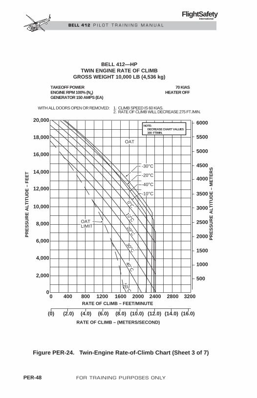
PER-48 FOR TRAINING PURPOSES ONLY
FlightSafety International
BELL 412 P I L O T T R A I N I N G M A N U A L
TAKEOFF POWERENGINE RPM 100% (N2)GENERATOR 150 AMPS (EA)
WITH ALL DOORS OPEN OR REMOVED: 1. CLIMB SPEED IS 60 KIAS.2. RATE OF CLIMB WILL DECREASE 275 FT./MIN.
70 KIASHEATER OFF
20,000
18,000
16,000
14,000
12,000
10,000
8,000
6,000
4,000
2,000
00 400 800 1200 1600 2000 2400 2800 3200
500
(0) (2.0) (4.0) (6.0) (8.0) (10.0) (12.0)
RATE OF CLIMB – (METERS/SECOND)
RATE OF CLIMB – FEET/MINUTE
PR
ES
SU
RE
AL
TIT
UD
E –
FE
ET
PR
ES
SU
RE
AL
TIT
UD
E –
ME
TE
RS
(14.0) (16.0)
1000
1500
2000
2500
3000
3500
4000
4500
5000
5500
6000
-30°C
-20°C
-40°C
-10°C
OAT
OATLIMIT
0°C10°C
20°C30°C
40°C50°C
BELL 412—HPTWIN ENGINE RATE OF CLIMB
GROSS WEIGHT 10,000 LB (4,536 kg)
NOTE: DECREASE CHART VALUES 300 FT/MIN.
Figure PER-24. Twin-Engine Rate-of-Climb Chart (Sheet 3 of 7)

FOR TRAINING PURPOSES ONLY PER-49
FlightSafety International
BELL 412 P I L O T T R A I N I N G M A N U A L
MAXIMUM CONTINUOUS POWERENGINE RPM 100% (N2)GENERATOR 150 AMPS (EA)
WITH ALL DOORS OPEN OR REMOVED: 1. CLIMB SPEED IS 60 KIAS.2. RATE OF CLIMB WILL DECREASE 275 FT./MIN.
70 KIASHEATER ON
20,000
18,000
16,000
14,000
12,000
10,000
8,000
6,000
4,000
2,000
00 200 400 600 800 1000 1200 1400 1600
500
(0) (1.0) (2.0) (3.0) (4.0) (5.0) (6.0)
RATE OF CLIMB – (METERS/SECOND)
RATE OF CLIMB – FEET/MINUTE
PR
ES
SU
RE
AL
TIT
UD
E –
FE
ET
PR
ES
SU
RE
AL
TIT
UD
E –
ME
TE
RS
(7.0) (8.0)
1000
1500
2000
2500
3000
3500
4000
4500
5000
5500
6000
OAT–20°C–30°C
–40°C
10°C
20°C
–10°C0°C
BELL 412TWIN ENGINE RATE OF CLIMB
GROSS WEIGHT 10,000 LB (4,536 kg)
Figure PER-24. Twin-Engine Rate-of-Climb Chart (Sheet 4 of 7)

PER-50 FOR TRAINING PURPOSES ONLY
FlightSafety International
BELL 412 P I L O T T R A I N I N G M A N U A L
MAXIMUM CONTINUOUS POWERENG—100% RPM (N2)GENERATOR 150 AMPS (EA)
WITH ALL DOORS OPEN OR REMOVED: 1. CLIMB SPEED IS 60 KIAS.2. RATE OF CLIMB WILL DECREASE 275 FT./MIN.
70 KIASHEATER OFF
20,000
18,000
16,000
14,000
12,000
10,000
8,000
6,000
4,000
2,000
00 200 400 600 800 1000 1200 1400 1600
500
(0) (1.0) (2.0) (3.0) (4.0) (5.0) (6.0)
RATE OF CLIMB – (METERS/SECOND)
RATE OF CLIMB – FEET/MINUTE
PR
ES
SU
RE
AL
TIT
UD
E –
FE
ET
PR
ES
SU
RE
AL
TIT
UD
E –
ME
TE
RS
(7.0) (8.0)
1000
1500
2000
2500
3000
3500
4000
4500
5000
5500
6000
OAT–40°C
OAT LIMIT
–30°C
–20°C–10°C0°C
10°C
20°C
30°C
40°C50°C
BELL 412—SPTWIN ENGINE RATE OF CLIMB
GROSS WEIGHT 10,000 LB (4,536 kg)
Figure PER-24. Twin-Engine Rate-of-Climb Chart (Sheet 5 of 7)

FOR TRAINING PURPOSES ONLY PER-51
FlightSafety International
BELL 412 P I L O T T R A I N I N G M A N U A L
BELL 412—HPTWIN ENGINE RATE OF CLIMB
GROSS WEIGHT 11,000 LB (4,990 kg)
MAXIMUM CONTINUOUS POWERENG INE RPM 100% (N2) GENERATOR 150 AMPS (EA)
WITH ALL DOORS OPEN OR REMOVED: 1. CLIMB SPEED IS 60 KIAS.2. RATE OF CLIMB WILL DECREASE 275 FT./MIN.
70 KIASHEATER OFF
20,000
18,000
16,000
14,000
12,000
10,000
8,000
6,000
4,000
2,000
00 400 600200 800 1200 14001000 1600
500
(0) (2.0)(1.0) (4.0)(3.0) (6.0)(5.0) (8.0)(7.0)
RATE OF CLIMB — (METERS/SECOND)
RATE OF CLIMB — FEET/MINUTE
PR
ES
SU
RE
AL
TIT
UD
E —
FE
ET
PR
ES
SU
RE
AL
TIT
UD
E —
ME
TE
RS
1000
1500
2000
2500
3000
3500
4000
4500
5000
5500
6000
–40°C–30°C–20°C
OAT
OAT LIMIT
0°C
10°C
–10°C
20°C
30°C
40°C
50°C
NOTE: DECREASE CHART VALUES 300 FT/MIN.
Figure PER-24. Twin-Engine Rate-of-Climb Chart (Sheet 6 of 7)

PER-52 FOR TRAINING PURPOSES ONLY
FlightSafety International
BELL 412 P I L O T T R A I N I N G M A N U A L
TWIN ENGINE RATE OF CLIMBGROSS WEIGHT 10,000 LB (4,536 kg)
MAXIMUM CONTINUOUS ENG POWERENGINE RPM 100% GENERATOR 150 AMPS (EA)
WITH ALL DOORS OPEN OR REMOVED: 1. CLIMB SPEED IS 60 KIAS.2. RATE OF CLIMB WILL DECREASE 275 FT./MIN.
70 KIASHEATER OFF
20,000
18,000
16,000
14,000
12,000
10,000
8,000
6,000
4,000
2,000
00 400 800 1200 1600 2000 2400 2800 3200
500
(0) (2.0) (4.0) (6.0) (8.0) (10.0) (12.0)RATE OF CLIMB – (METERS/SECOND)
RATE OF CLIMB – FEET/MINUTE
PR
ES
SU
RE
AL
TIT
UD
E –
FE
ET
PR
ES
SU
RE
AL
TIT
UD
E –
ME
TE
RS
(14.0) (16.0)
1000
1500
2000
2500
3000
3500
4000
4500
5000
5500
6000
OAT
-30°C
-20°C
-40°C
-10°C
OATLIMIT
0°C40°C
50°CC
ON
T XM
SN
5 MIN
XM
SN
10°C20°C
30°CNOTE: DECREASE CHART VALUES 300 FT/MIN
Figure PER-24. Twin-Engine Rate-of-Climb Chart (Sheet 7 of 7)

SINGLE-ENGINE RATE-OF-CLIMB CHARTSThe Single Engine Rate of Climb charts (Figure PER-25) provide the ratesof climb that can be obtained at all outside air temperatures/pressure alti-tudes/gross weight combinations with heater off at maximum continuouspower and 30-minute OEI power.
NOTEPublished single engine performance is intended foremergency use only when one engine becomes in-operative due to an actual malfunction. Routine op-eration in excess of published twin engine operatinglimits can affect engine service life.
The charts differ depending on gross weight and if 30-minute OEI power ormaximum continuous power is used. All charts are based on doors on andclosed, one engine operating at 97 % N2, its generator loaded to 150 amperes,the other engine secured, the heater off, and 70 KIAS. The chart headings alsoinclude airspeed and ROC adjustments for climb with the helicopter's doorsopen or removed.
Single-engine performance is provided for emergency use only. Positive ratesof climb are very low for the lightest gross weights and nonexistent or neg-ative for heavier gross weights.
Since a zero rate of climb is the same as level flight, the single-engine rate-of-climb charts can be used to determine the pressure altitude and/or maxi-mum gross weight that can be maintained in level flight if an engine fails. Thiscalculation can be very important if operating in high, mountainous terrain.
The calculation to determine the PA that can be maintained in level flight re-quires an estimate of the OAT and then working the appropriate chart in reverse.To determine the MGW that can be maintained at a given PA again requires anestimate of the OAT at that altitude and the checking of several charts.
FOR TRAINING PURPOSES ONLY PER-53
FlightSafety International
BELL 412 P I L O T T R A I N I N G M A N U A L

PER-54 FOR TRAINING PURPOSES ONLY
FlightSafety International
BELL 412 P I L O T T R A I N I N G M A N U A L
30 MINUTE OEI POWERENG – 97% RPM (N2) GENERATOR 150 AMPS (EA)
WITH ALL DOORS OPEN OR REMOVED: 1. CLIMB SPEED IS 60 KIAS.2. RATE OF CLIMB WILL DECREASE 275 FT./MIN.
70 KIASHEATER OFF
INOPERATIVE ENGINE SECURED
20,000
18,000
16,000
14,000
12,000
10,000
8,000
6,000
4,000
2,000
0-2000 -1600 -1200 -800 -400 0 400 800 1200
500
(-10.0) (-8.0) (-6.0) (-4.0) (-2.0) (0) (2.0)RATE OF CLIMB – (METERS/SECOND)
RATE OF CLIMB – FEET/MINUTE
PR
ES
SU
RE
ALT
ITU
DE
– F
EE
T
PR
ES
SU
RE
ALT
ITU
DE
– M
ET
ER
S
(4.0) (6.0)
1000
1500
2000
2500
3000
3500
4000
4500
5000
5500
6000
OAT LIMIT
-10°C0°C
10°C20°C
30°C40°C
50°C
OAT-20°C-30°C-40°CTWIN ENGINE M C P
ABSOLUTE CEILING
BELL 412/SPSINGLE-ENGINE RATE-OF-CLIMB
GROSS WEIGHT 10,000 LB (4536 KG)
Figure PER-25. Single-Engine Rate-of-Climb Chart (Sheet 1 of 3)
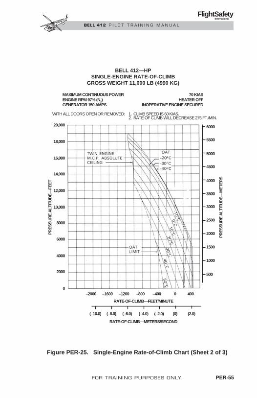
FOR TRAINING PURPOSES ONLY PER-55
FlightSafety International
BELL 412 P I L O T T R A I N I N G M A N U A L
BELL 412—HPSINGLE-ENGINE RATE-OF-CLIMB
GROSS WEIGHT 11,000 LB (4990 KG)
MAXIMUM CONTINUOUS POWERENGINE RPM 97% (N2)GENERATOR 150 AMPS
WITH ALL DOORS OPEN OR REMOVED: 1. CLIMB SPEED IS 60 KIAS.2. RATE OF CLIMB WILL DECREASE 275 FT./MIN.
70 KIASHEATER OFF
INOPERATIVE ENGINE SECURED
0
20,000
18,000
16,000
14,000
12,000
10,000
8000
6000
4000
2000
–2000 –1600 –1200 –800 –400 0 400
500
6000
5500
5000
4500
4000
3500
3000
2500
2000
1500
1000
(–10.0) (2.0)(0)(–2.0)(–4.0)(–6.0)(–8.0)
RATE-OF-CLIMB—FEET/MINUTE
RATE-OF-CLIMB—METERS/SECOND
PR
ES
SU
RE
ALT
ITU
DE
—FE
ET
PR
ES
SU
RE
ALT
ITU
DE
—M
ETE
RS
Figure PER-25. Single-Engine Rate-of-Climb Chart (Sheet 2 of 3)

PER-56 FOR TRAINING PURPOSES ONLY
FlightSafety International
BELL 412 P I L O T T R A I N I N G M A N U A L
WITH ALL DOORS OPEN OR REMOVED: 1. CLIMB SPEED IS 60 KIAS.2. RATE OF CLIMB WILL DECREASE 275 FT./MIN.
20,000
18,000
16,000
14,000
12,000
10,000
8,000
6,000
4,000
2,000
0-2000 -1600 -1200 -800 -400 0 400 800 1200
500
(-10.0) (-8.0) (-6.0) (-4.0) (-2.0) (0) (2.0)RATE OF CLIMB – (METERS/SECOND)
RATE OF CLIMB – FEET/MINUTE
PR
ES
SU
RE
AL
TIT
UD
E –
FE
ET
PR
ES
SU
RE
AL
TIT
UD
E –
ME
TE
RS
(4.0) (6.0)
1000
1500
2000
2500
3000
3500
4000
4500
5000
5500
6000
OAT LIMIT
-10°C0°C
10°C20°C
30°C40°C
50°C
OAT-20°C-30°C-40°CTWIN ENGINE M C P
ABSOLUTE CEILING
BELL 412—EPSINGLE-ENGINE RATE-OF-CLIMB
GROSS WEIGHT 10,000 LB (4536 KG)
MAXIMUM CONTINUOUS POWERENGINE RPM 97% (N2)GENERATOR 150 AMPS
70 KIASHEATER OFF
INOPERATIVE ENGINE SECURED
Figure PER-25. Single-Engine Rate-of-Climb Chart (Sheet 3 of 3)

LANDING DISTANCEThe Single Engine Landing Distance chart (Figure PER-26) provides thelanding distance required to clear a 50-foot (15-meter) obstacle for all out-side air temperatures, pressure altitudes, and gross weights. Landing distancesare based on an approach condition of 45 KIAS and 500 feet per minute rateof descent, zero wind.
Revision 1 FOR TRAINING PURPOSES ONLY PER-57
FlightSafety International
BELL 412 P I L O T T R A I N I N G M A N U A L
14,000 FT. DEN. ALT. LIMIT
ALL MODELSSINGLE ENGINE LANDING DISTANCE
OVER 50 FT. (15 M) OBSTACLE21/2 MINUTE OEI POWER AS REQUIREDENGINE RPM 97%GENERATOR 150 AMPS
45 KIASRATE OF DESCENT 500 FT/MHARD SURFACED RUNWAY
INOPERATIVE ENGINE SECURED
MAX. OAT
MIN. OAT
LANDING DISTANCEALL GROSS WEIGHTS
14,0
00
12,0
00
10,0
00
8,00
0 6,
000
4,00
0 2,
000
-2,0
00 S
EA
LE
VE
L P
RE
SS
UR
E A
LTIT
UD
E –
–40 –20 0 20 40 60 200 400 600 800 1000 1200 FEETMETERSOAT — °C
LANDING DISTANCE50 100 150 200 250 300 350 400
Figure PER-26. Single-Engine Landing Distance Chart

AIRSPEED CALIBRATION CHARTThe single airspeed calibration chart allows the pilot to calculate calibratedversus indicated airspeeds for climb, level flight, and autorotation. This chartcan be used in conjunction with the true airspeed factor obtained from the den-sity altitude chart to convert KIAS to KCAS to KTAS.
The Airspeed Calibration chart (Figure PER-27) provides calibrated air-speeds for all indicated airspeeds during level flight, climb, and autorotation.
PER-58 FOR TRAINING PURPOSES ONLY
FlightSafety International
BELL 412 P I L O T T R A I N I N G M A N U A L
PILOT AND COPILOT AIRSPEEDSYSTEM CALIBRATION
CLIMB, LEVEL FLIGHT, AUTOROTATION
SKID GEAR KIAS — ERROR = KCAS
0
20
40
60
80
100
120
140
160
0 20 40 60 80 100 120 140 160
INDICATED AIRSPEED — KNOTS
CA
LIB
RA
TE
D A
IRS
PE
ED
— K
NO
TS
LEVEL FLIGHT
AUTOROTATION
CLIMB
Figure PER-27. Airspeed Calibration Chart

MOST EFFICIENT AIRSPEEDWhile never specifically mentioned in the RFM, numerous performance chartsand procedures are based on the helicopter's most efficient airspeed. Amongthese are the rate-of-climb and fuel flow vs airspeed charts and the airspeedfor engine failure procedure.
Helicopter flight produces three forms of drag: profile drag associated withrotation of the rotor systems through the air, induced drag which occurs whenthe rotor system produces lift, and parasite drag that develops when the non-lift producing parts of the helicopter are moved through the air. Each form ofdrag requires a corresponding form of power to overcome the drag effects(Figure PER-28).
Profile power overcomes profile drag and remains fairly constant through-out the helicopter flight envelope.
Induced power required is very high during hovering, when the rotor must pro-duce all its own lift, and increases very slightly just before the helicopter enterstranslational lift. After translational lift, the induced airflow through the rotoras a result of forward airspeed reduces the need for induced power significantly.
In a hover there is no parasite drag from the fuselage. However, as forwardflight airspeed increases, so does parasite drag, and the requirement for par-asite power increases proportionally.
The helicopter’s most efficient airspeed is that at which the sum total of allthree types of power is the lowest.
FOR TRAINING PURPOSES ONLY PER-59
FlightSafety International
BELL 412 P I L O T T R A I N I N G M A N U A L
POWER
PROFILE POWER
AIRSPEED
INDUCED POWER
PARASITE POWER
10%
100%
90%
80%
70%
60%
50%
40%
30%
20%
10 1501401301201101009080706050403020
Figure PER-28. Power Required (Typical)

NOISE LEVELSCERTIFICATIONThis aircraft is certified as a Stage 2 helicopter as prescribed in FAR Part36, Subpart H, for gross weights up to and including the certificated maxi-mum takeoff and landing weight of 11,900 pounds (5,398 kilograms). Thereare no operating limitations in meeting the takeoff, flyover, or approachnoise requirements.
The following noise levels comply with FAR Part 36, Appendix H, Stage 2 noiselevel requirements. They were obtained by analysis of approved data fromnoise tests conducted under the provisions of FAR Part 36, Amendment 36-14.
The certified noise levels are:
Flight Condition EPNL (EPNdB)Takeoff 92.8Flyover 93.4Approach 95.6
NOTENo determination has been made by the FederalAviation Administration that the noise levels of thisaircraft are or should be acceptable or unacceptablefor operation at, into, or out of any airport.
VH is defined as the airspeed in level flight obtained using the minimumspecification engine torque corresponding to maximum continuous power avail-able for sea level 25° C ambient conditions at the relevant maximum certifi-cated weight. The value of VH thus defined for this helicopter is 122 KTAS.
SUPPLEMENTAL INFORMATIONThe test and analysis procedures used to obtain these noise levels are es-sentially equivalent to those required by the International Civil AviationOrganization (ICAO) in Annex 16, Volume 1, Chapter 8. Approval is ap-plicable only after endorsement by the Civil Aviation Authority of the coun-try of aircraft registration.
PER-60 FOR TRAINING PURPOSES ONLY
FlightSafety International
BELL 412 P I L O T T R A I N I N G M A N U A L

FOR TRAINING PURPOSES ONLY PER-61
FlightSafety International
BELL 412 P I L O T T R A I N I N G M A N U A L
CATEGORY A OPERATIONSMost Bell 412s are operated under FAR Part 29 Category B operations, andthe majority of the RFM limitations and performance charts are based onCategory B.
Category A helicopter operation may be required if:
• The helicopter is operating under a FAR Part 133, 135, or 127 certificate.
• The responsible FAA principal operations inspector requires the cer-tificate holder to follow Category A operations for certain types ofhelicopter flights.
• The party owning, operating, or hiring the helicopter requires that theflight should be conducted under Category A.
Category A operation increases margins of safety during the takeoff andlanding/approach phases of flight. Category A does not increase helicoptersafety itself, but rather safety in the way it is operated.
Briefly, Category A requires helicopter operation in such a manner that if anengine fails during takeoff or landing approach, either a safe landing orclimbing and attaining single-engine forward flight is possible. The increasedsafety is achieved by significantly reducing maximum gross weight and max-imum altitude for takeoff and landing and by increasing takeoff and landingdistances required.
For example, given an OAT of 40°C (104°F) at a pressure altitude of 4,000feet, the Category B maximum gross weight for takeoff and landing is 10,500pounds. Under the same conditions, the maximum gross weight for CategoryA operations is only 8,020 pounds. The large reduction in takeoff and land-ing gross weight substantially increases the margin of safety if an engine shouldfail (Figures PER-29).

PER-62 FOR TRAINING PURPOSES ONLY
FlightSafety International
BELL 412 P I L O T T R A I N I N G M A N U A L
4,000
–1,000
1,000
0
2,000
3,000
74 100989694929088868482807876
34 4544434241403938373635
GROSS WEIGHT
PR
ES
SU
RE
ALT
ITU
DE
~FE
ET
8020 LB
~ lb X 100
~ kg X 100
MA
X O
AT
MAX OAT
45°C
51.7°C
50°C
20°C
30°C
25°C
35°C
40°CWEIGHT — ALTITUDE — TEMPERATURE FOR TAKEOFF AND LANDING
PART AVTOSS = 40 KIAS GW TO 10,000 LBS (4536 kg)
Figure PER-29. Category A Operations

FUEL FLOW VS AIRSPEEDThe fuel flow vs airspeed charts may be used to obtain spproximate fuelflow based on KTAS or KIAS. Since these charts are based on limited testdata, actual fuel consumption may vary according to external factors. Thefigures calculated should not be used as a definite standard for fuel con-sumption (Figure PER-30).
Each fuel flow vs airspeed charts is based on a different pressure altitudeand OAT. Since not all combinations of pressure altitude and OAT are in-cluded and the effects of bleed air and drag from additional equipment arenot accounted for, it is recommended that pilots establish their own mea-surements of fuel flow. Adjustment charts are included for the effects ofpop-out floats.
FOR TRAINING PURPOSES ONLY PER-63
FlightSafety International
BELL 412 P I L O T T R A I N I N G M A N U A L

PER-64 FOR TRAINING PURPOSES ONLY
FlightSafety International
BELL 412 P I L O T T R A I N I N G M A N U A L
FUEL FLOW VS AIRSPEED
PRESSURE ALTITUDE = 2000 FEET
OAT = +11°C
TWIN ENGINE OPERATION ZERO WIND
FUEL FLOW INCREASE FOR POP-OUT FLOATS
TRUE AIRSPEED—KNOTS
TRUE AIRSPEED—KNOTS
INDICATED AIRSPEED—KNOTS
Δ TO
RQ
UE
—%
QTO
RQ
UE
—%
Q
Δ F
UE
L F
LO
W—
100
LB
/HR
FU
EL
FL
OW
—10
0 L
B/H
R
CLEAN CONFIGURATION
90
80
10
20
30
40
50
60
70
0 0
3
2
1
10
20
3
4
5
6
7
8
90 1401301201101008060 70
90 1401301201101008060 70
90 1401301201101008060 70
412099-6-5
XMSN LIM
GW —
8
12
1110
9
7
LRC
MAX END
VN
E
Figure PER-30. Fuel Flow vs Airspeed Charts

SYLLABUS/CURRICULUMCONTENTS
Page
INTRODUCTION........................................................................... SYL-1
GENERAL INFORMATION.......................................................... SYL-1
PROGRAMMED TRAINING HOURS.......................................... SYL-1
GROUND SCHOOL MODULES................................................... SYL-2
GENERAL OPERATIONALSUBJECTS MODULES.................................................................. SYL-2
Module 1—Weight and Balance........................................... SYL-2
Module 2—Performance ...................................................... SYL-2
Module 3—Flight Planning .................................................. SYL-2
Module 4—RotorcraftFlight Manual (RFM) ............................................................ SYL-2
Module 5—Windshear.......................................................... SYL-2
Module 6—Crew ResourceManagement (CRM).............................................................. SYL-2
AIRCRAFT SYSTEMS MODULES.............................................. SYL-3
Module 1—Aircraft General................................................. SYL-3
Module 2—Powerplant ......................................................... SLY-3
Module 3—Air Management................................................ SYL-3
Module 4—Fire Protection ................................................... SYL-3
Module 5—Fuel System ....................................................... SYL-3
Module 6—Electrical System............................................... SYL-3
Module 7—Lighting ............................................................. SYL-3
Module 8—Master Warning System .................................... SYL-3
Module 9—Powertrain ......................................................... SYL-4
Module 10—Main Rotor ....................................................... SYL-4
Module 11—Tail Rotor.......................................................... SYL-4
Module 12—Flight Controls/AFCS ...................................... SYL-4
Module 13—Hydraulic .......................................................... SYL-4
Module 14—Ice and Rain Protection .................................... SYL-4
APRIL 1999 FOR TRAINING PURPOSES ONLY SYL-i
FlightSafety International
BELL 412 P I L O T T R A I N I N G M A N U A L

Module 15—Environmental .................................................. SYL-4
Module 16—Avionics............................................................ SYL-4
Module 17—Kits and Accessories ........................................ SYL-5
Module 18—Preflight ............................................................ SYL-5
Module 19—Review.............................................................. SYL-5
FLIGHT TRAINING MODULE OUTLINES................................ SYL-5
Simulator Module No. 1 ........................................................ SYL-5
Simulator Module No. 2 ........................................................ SYL-7
Simulator Module No. 3 (Practical Test) ................................ SYL-8
Competency Check, ProficiencyCheck, or Flight Review Check(Checks IAW 61.56, 61.57, 135.293or 135.297 as Appropriate) .................................................... SYL-9
COMPLETION STANDARDS....................................................... SYL-9
SYL-ii FOR TRAINING PURPOSES ONLY APRIL 1999
FlightSafety International
BELL 412 P I L O T T R A I N I N G M A N U A L

SYLLABUS/CURRICULUM
INTRODUCTIONThis syllabus has been prepared to serve as a general outline to assist you whileyou attend this course. Normally it serves as a guide for the instructor, butdeviations will occur. Occasionally changes must be made due to unforeseencircumstances to accommodate training in the most effective manner. If someitems are not covered where or when indicated, they will be covered at a dif-ferent time.
GENERAL INFORMATIONThe pilot recurrent training consists of the following:
NON-PART 142 PART 142
• Classroom hours .......................................... 12.0* 12.0*
• Simulator hours (includessystems integration) ........................................ 6.0 4.5
• Briefing hours .................................................. 2.0 3.0
• Total.................................................................. 20.0 19.5
*Up to 12 hours of optional subjects are offered.
Four days should be allowed for accomplishment of the complete program.
PROGRAMMED TRAINING HOURSFollowing are the subjects and planned classroom hours for the pilot recur-rent ground school:
• General Operational Subjects .......................................................... 2.0
• Systems Training ................................................................................ 8.0
• Preflight ................................................................................................ 1.0
• Examination and Critique .................................................................. 1.0
• Total .................................................................................................... 12.0
APRIL 1999 FOR TRAINING PURPOSES ONLY SYL-1
FlightSafety International
BELL 412 P I L O T T R A I N I N G M A N U A L

GROUND SCHOOL MODULESThe ground school modules will consist of instructor guided classroom dis-cussions using ACPS/computer generated slides to present a review of the Bell412. The primary objective is to review all aircraft limitations, normal pro-cedures, emergency and malfunction procedures, aircraft systems, and crewresource management and aeronautical decision making skills. All instruc-tion is based on pilot operation of the aircraft systems and controls duringnormal and abnormal systems operation.
GENERAL OPERATIONALSUBJECTS MODULESMODULE 1—WEIGHT AND BALANCEModule 1 is a thorough review regarding the center of gravity (CG). Itemsto be covered will include weight and balance limits, data, and cockpit andcabin loading.
MODULE 2—PERFORMANCEModule 2 is a review of Section 4 of the Rotorcraft Flight Manual (RFM), withemphasis on power assurance checks, hover power charts, takeoff and OEI land-ing distance charts, and twin engine and single engine rate-of-climb charts.
MODULE 3—FLIGHT PLANNINGModule 3 will cover essential data operations and limitations pertinent to flight.
MODULE 4—ROTORCRAFT FLIGHT MANUAL (RFM)Module 4 will cover the organization of the RFM to include applicability ofthe RFM, the RFM sections, manufacturer’s data, and RFM supplements; andwill also cover terminology and use of procedural words.
MODULE 5—WINDSHEARModule 5 will review windshear with a low level temperature inversion in afrontal zone associated with thunderstorms and microbursts.
MODULE 6—CREW RESOURCE MANAGEMENT (CRM)Module 6 will be an insight into the critical areas of cockpit resource man-agement. The emphasis of this lesson will be on the factors influencing lossof situational awareness and the error chain, effective communications,workload and time management, elements of a quality briefing, reliance on
SYL-2 FOR TRAINING PURPOSES ONLY APRIL 1999
FlightSafety International
BELL 412 P I L O T T R A I N I N G M A N U A L

automation, decision making and judgement errors, and effects of and cop-ing with stress.
AIRCRAFT SYSTEMS MODULESMODULE 1—AIRCRAFT GENERALModule 1 will be a review of the Bell 412 origin, development, and perfor-mance; the major aircraft sections, dimensions and structure; crew and pas-senger compartments; and parking, mooring and towing.
MODULE 2—POWERPLANTModule 2 will be a review of the Pratt and Whitney PT6T Twinpac engine sys-tems, their operation, associated malfunctions and malfunction procedures.
MODULE 3—AIR MANAGEMENTModule 3 will review the purposes and characteristics of the Air ManagementSystem, components, normal operation, malfunctions and corrective actions.
MODULE 4—FIRE PROTECTIONModule 4 will be a review of the engine fire detection system, the engine fire ex-tinguishing system, and the baggage compartment smoke/fire detection system.
MODULE 5—FUEL SYSTEMModule 5 will be a review of the fuel storage system capacity, components,and operation, fuel supply system components and operation, fuel quantityindicating system, and fuel system malfunctions and procedures.
MODULE 6—ELECTRICAL SYSTEMModule 6 will be a review of electrical system types and purposes, distribution, con-trol, indications, sources, DC and AC power flows, and electrical power systemsmalfunctions.
MODULE 7—LIGHTINGModule 7 will be a review of the aircraft interior and exterior lighting.
MODULE 8—MASTER WARNING SYSTEMModule 8 will be a review of the master caution/warning system, caution panelsegment lights, and other caution and warning lights.
APRIL 1999 FOR TRAINING PURPOSES ONLY SYL-3
FlightSafety International
BELL 412 P I L O T T R A I N I N G M A N U A L

MODULE 9—POWERTRAINModule 9 will be a review of the powertrain components, main driveshaft,main transmission, main transmission lubrication system, main transmis-sion subsystems, tail rotor drive system, and tail rotor malfunctions.
MODULE 10—MAIN ROTORModule 10 will be a review of the type of main rotor used on the Bell 412, move-ment of the individual blades, the main rotor improvements, characteristics andconstruction of the main rotor blades, and the main rotor system limitations.
MODULE 11—TAIL ROTORModule 11 will be a review of the tail rotor used on the Bell 412, the charac-teristics and operation of each of the three tail rotor subassemblies: the tail rotorhub assembly, the tail rotor blades, and the tail rotor pitch change mechanism.
MODULE 12—FLIGHT CONTROLS/AFCSModule 12 will be a review of the collective flight control system, the cyclicflight control system, the antitorque flight control system, the force trim sys-tem, the aerodynamic elevator, and AFCS/DAFCS.
MODULE 13—HYDRAULICSModule 13 will be a review of the Bell 412 hydraulic systems to include thehydraulic system components, operations, and malfunctions.
MODULE 14—ICE AND RAIN PROTECTIONModule 14 will be a review of the operating procedures of the pitot/static heatersystem, the operating procedures and limitations of the windshield wipersystem, and the operating procedures of defrosting and defogging systems,and the operating procedures and limitations of each.
MODULE 15—ENVIRONMENTALModule 15 will be a review of the environmental systems, cockpit and cabinheating system, and cockpit ventilation system.
MODULE 16—AVIONICSModule 16 will be a review of the function and operation of the generalavionics system in the Bell 412 helicopter. The King Gold Crown seriesequipment will be discussed.
SYL-4 FOR TRAINING PURPOSES ONLY APRIL 1999
FlightSafety International
BELL 412 P I L O T T R A I N I N G M A N U A L

MODULE 17—KITS AND ACCESSORIESModule 17 will be a review of the basic components and operation of the kitsand accessories to include: emergency floatation system, heated windshields,auxiliary fuel tanks, flight director, litter kit, external cargo hook, weatherradar, and internal rescue hoist.
MODULE 18—PREFLIGHTModule 18 will be a pilot walkaround and interior check of the Bell 412 uti-lizing the preflight check in the Rotorcraft Flight Manual.
MODULE 19—REVIEWDuring Module 19, the pilot will successfully complete a multiple choice ex-amination for which a minimum score of 70% is required for Non-Part 142and 80% for Part 142 requirements. Each incorrect response will be critiqued.
FLIGHT TRAINING MODULE OUTLINESThis course provides 4.5 or 6.0 hours PIC training in the Bell 412 flight sim-ulator. When training as crew, each pilot receives an additional 4.5 or 6.0 hoursin the copilot position. Simulator flights are 1.5 or 2.0 hours, during whicha wide variety of normal and malfunction/emergency procedures are practiced.The degree of complexity and the challenge of each mission progresses to thetesting or checking applicable to the curriculum.
As a pilot’s proficiency and job requirements vary, each pilot will be trainedin the environment most closely approximating his/her flying requirements(i.e. VFR, VFR/IFR, offshore, EMS, military, air taxi, corporate, etc.).
SIMULATOR MODULE NO. 1A. Flight Training Events
1. Preparation
a. Preflight
b. Performance Limitations
2. Surface Operations
a. Powerplant Start
b. Pretakeoff Checks
APRIL 1999 FOR TRAINING PURPOSES ONLY SYL-5
FlightSafety International
BELL 412 P I L O T T R A I N I N G M A N U A L

3. Takeoff
a. Hover Taxi
b. Air Taxi
c. Normal and Crosswind Takeoff
4. Climb
a. Normal
b. Traffic Patterns
5. Landings
a. Normal and Crosswind Landing
b. Single Engine Landing
6. After Landing Procedures
a. Parking
B. Systems Procedures (Normal/Abnormal)
1. Flight Controls
2. Fire Detection and Extinguishing
3. Navigation and Avionics Equipment
4. AFCS, EFIS (As Applicable)
5. Engine System
C. Other Flight Procedures
1. Confined Area Operations
2. Pinnacle/Platform Operation
3. Rapid Deceleration
SYL-6 FOR TRAINING PURPOSES ONLY APRIL 1999
FlightSafety International
BELL 412 P I L O T T R A I N I N G M A N U A L

SIMULATOR MODULE NO. 2A. Review of Previous Flight
B. Flight Training Events
1. Takeoff
a. Instrument Takeoff
b. Maximum Performance Takeoff & Climb
2. Enroute
a. Single Engine Procedures
b. Steep Turns
c. Recovery from Unusual Attitudes
d. Settling with Power
3. Approaches
a. Area Departure and Arrival
b. Precision Approach (Coupled)
c. Nonprecision Approach
d. Missed Approach
e. Precision Approach with One Engine Inoperative
f. Steep Approach
g. Shallow Approach and Running Landing
4. Landings
a. Go Around
5. Other Flight Procedures
a. Holding
APRIL 1999 FOR TRAINING PURPOSES ONLY SYL-7
FlightSafety International
BELL 412 P I L O T T R A I N I N G M A N U A L

C. Systems Procedures (Normal/Abnormal)
1. Electrical (AC and DC)
2. Flight Control Systems
3. Anti-ice and Deice Systems
4. Emergency Equipment
5. Loss of Tail Rotor Effectiveness (Oral Only)
6. Powerplant
7. Fuel System
8. Electrical
9. Hydraulics
D. System Procedures (Emergency)
1. Inflight Fire and Smoke Removal
2. Transmission
3. Tail Rotor
4. Fuel System
5. Engine Oil Systems
6. Hydraulic System Failure (#1 or #2)
SIMULATOR MODULE NO. 3 (PRACTICAL TEST)A. Flight Training Events
1. Preflight Procedures
2. Ground Operations
3. Takeoff and Departure Maneuvers
4. Inflight Maneuvers
5. Instrument Procedures
6. Landings and Approaches to Landings
7. Normal and Abnormal Procedures
SYL-8 FOR TRAINING PURPOSES ONLY APRIL 1999
FlightSafety International
BELL 412 P I L O T T R A I N I N G M A N U A L

8. Emergency Procedures
9. Postflight Procedures
COMPETENCY CHECK, PROFICIENCY CHECK, ORFLIGHT REVIEW (CHECKS IAW 61.56, 61.57, 135.293 OR135.297 AS APPROPRIATE)A flight training module in which the pilot shall demonstrate in the languageof FAR 61.43: “Show that he is the master of the aircraft, with the success-ful outcome of the maneuver never seriously in doubt.” Or, in the languageof FAR 135.293: “. . .the pilot must be the obvious master of the aircraft, withthe successful outcome of the maneuver never in doubt.”
COMPLETION STANDARDSThe pilot must demonstrate satisfactory performance through behavioralchecks and examinations in the classroom and in the simulator to insure skillrequirements have been demonstrated to maintain pilot-in-command status.
APRIL 1999 FOR TRAINING PURPOSES ONLY SYL-9
FlightSafety International
BELL 412 P I L O T T R A I N I N G M A N U A L

MASTER WARNING SYSTEMCONTENTS
Page
INTRODUCTION ........................................................................ MWS-1
GENERAL ................................................................................... MWS-1
CAUTION PANEL ....................................................................... MWS-1
FOR TRAINING PURPOSES ONLY MWS-i
FlightSafety International
BELL 412 P I L O T T R A I N I N G M A N U A L

ILLUSTRATIONSFigure Title Page
MWS-1 Annunciators—SNs 33001–33107 .......................... MWS-8
MWS-2 Annunciators—SNs 33108 and Subsequent ............ MWS-9
MWS-3 Annunciators—SNs 36087 and Subsequent ............ MWS-9
TABLESTable Title Page
MWS-1 Caution Panel Caution/Warning Lights .................... MWS-2
MWS-2 Additional Caution/Warning Lights ........................ MWS-6
FOR TRAINING PURPOSES ONLY MWS-iii
FlightSafety International
BELL 412 P I L O T T R A I N I N G M A N U A L

MASTER WARNING SYSTEM
INTRODUCTIONThe caution/warning system of the Bell 412 provides the pilot with immedi-ate notification of all major systems malfunctions. The majority of the cau-tion/warning lights are located on the caution panel. Additional caution/warninglights are located on the instrument panels, readily visible to both pilots. TwoMASTER CAUTION lights alert the pilot when any of the caution/warninglights illuminate..
GENERALThe caution/warning system includes: the caution panel, other caution/warn-ing lights for associated systems, the two MASTER CAUTION lights, cau-tion panel system switches, and associated electrical supply systems. Warninglights pertaining to systems that require the pilot’s immediate attention haveblack letters on a red background (red letters on a black background on SNs33108 and subsequent). Caution lights pertaining to systems that requireother than immediate attention have amber letters on a black background.
CAUTION PANELThe caution panel is located on the engine instrument panel. For Bell 412 SNs33001 through 33107, the panel contains 40 individual monitoring/detectingsystems and lights, all of which are functional. The caution panel for Bell SNs33108 through 36086 contains 54 lights of which 43 are functional, and BellSNs 36087 and Subsequent contains 54 lights, of which 47 are functional.
FOR TRAINING PURPOSES ONLY MWS-1
FlightSafety International
BELL 412 P I L O T T R A I N I N G M A N U A L
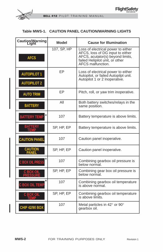
MWS-2 FOR TRAINING PURPOSES ONLY Revision 1
FlightSafety International
BELL 412 P I L O T T R A I N I N G M A N U A L
Table MWS-1. CAUTION PANEL CAUTION/WARNING LIGHTS
Caution/Warning Model Cause for Illumination Light
107, SP, HP Loss of electrical power to either AFCS, loss of DG input to either AFCS, acutator(s) beyond limits, failed Helipilot unit, or other AFCS malfunction.
EP Loss of electrical power to either Autopilot, or failed Autopilpt unit. Autopilot 1 or 2 Inoperative.
EP Pitch, roll, or yaw trim inoperative.
All Both battery switches/relays in the same position.
* 107 Battery temperature is above limits.
SP, HP, EP Battery temperature is above limits.
107 Caution panel inoperative.
SP, HP, EP Caution panel inoperative.
* 107 Combining gearbox oil pressure is below normal.
SP, HP, EP Combining gear box oil pressure is below normal.
* 107 Combining gearbox oil temperature is above normal.
SP, HP, EP Combining gearbox oil temperature is above limits.
107 Metal particles in 42° or 90° gearbox oil.
AFCS
AUTOPILOT 1
AUTOPILOT 2
AUTO TRIM
BATTERY
BATTERY TEMP
BATTERYTEMP
CAUTION PANEL
C BOX OIL PRESS
C BOX OIL TEMP
CHIP 42/90 BOX
CAUTIONPANEL
C BOX OILTEMP
C BOX OILPRESSURE

Revision 1 FOR TRAINING PURPOSES ONLY MWS-3
FlightSafety International
BELL 412 P I L O T T R A I N I N G M A N U A L
Table MWS-1. CAUTION PANEL CAUTION/WARNING LIGHTS (CONT)
Caution/Warning Model Cause for Illumination Light
SP, HP, EP Metal particles in 42° or 90° gearbox oil.
107 Metal particles in combining gearbox oil.
SP, HP, EP Metal particles in combining gearbox oil.
107 Metal particles in engine oil.
SP, HP, EP Metal particles in engine oil.
107 Metal particles in transmission oil.
SP, HP, EP Metal particles in transmission oil.
107 Generator has failed, is turned off, or is disconnected from the electrical system.
SP, HP, EP Generator has failed, is turned off, or is disconnected from the electrical system.
107 Passenger doors and/ or baggage compartment door are not locked.
SP, HP, EP Passenger doors and/ or baggage compartment door are not locked.
All External power connector door is open.
107 Indicated fuel boost pump, flow switch, or ejector pump has failed.
CHIP C BOX
CHIP
CHIP XMSN
42/90 BOXCHIP
ENGINECHIP
XMSNCHIP
DC GENERATOR
DOOR LOCK
FUEL BOOST
C BOXCHIP
EXTERNALPOWER
DOORLOCK
DCGENERATOR
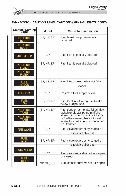
MWS-4 FOR TRAINING PURPOSES ONLY Revision 1
FlightSafety International
BELL 412 P I L O T T R A I N I N G M A N U A L
Table MWS-1. CAUTION PANEL CAUTION/WARNING LIGHTS (CONT)
Caution/Warning Model Cause for Illumination Light
SP, HP, EP Fuel boost pump failure has occurred.
107 Fuel filter is partially blocked.
SP, HP, EP Fuel filter is partially blocked.
SP, HP, EP Fuel interconnect valve not fully
closed.
107 Indicated fuel supply is low.
SP, HP, EP Fuel level in left or right cells at or below 190 pounds.
SP, HP, EP Fuel transfer pump has failed, flow switch or ejector pump malfunc- tioned. Prior to BH 412 SN 33168 or fuel has leaked back into mid underfloor cell after completion of fuel transfer. 107 Fuel valve not properly seated or circuit breaker out.
SP, HP, EP Fuel valve not properly seated or circuit breaker out.
107 Fuel crossfeed valve not fully open or closed.
SP, SH, EP Fuel crossfeed valve not fully open
FUEL FILTER
NO. 1 FUELBOOST
NO. 2 FUELBOOST
NO. 1 FUELFILTER
NO. 2 FUELFILTER
NO. 1 FUELTRANS
NO. 2 FUELTRANS
FUELINTCON
FUEL LOW
FUEL VALVE
FUEL XFEED
FUELVALVE
FUELXFEED
FUELLOW

Revision 1 FOR TRAINING PURPOSES ONLY MWS-5
FlightSafety International
BELL 412 P I L O T T R A I N I N G M A N U A L
Table MWS-1. CAUTION PANEL CAUTION/WARNING LIGHTS (CONT)
GEN OVHT
CAUTION/WARNING
LIGHTMODEL
107 Generator overheating.
SP, HP, EP Generator overheating.NO. 1 GENOVHT
NO. 2 GENOVHT
CAUSE FOR ILLUMINATION
107 Engine governor in manual modeGOV MANUAL
All Heater mixing valve has malfunction.HEATER AIR LINE
107 Hydraulic pressure is below limits or temperature is above limits.
HYDRAULIC
INVERTER 1
INVERTER 2
OIL PRESSURE
SP, HP, EP Hydraulic pressure is below limits or temperature is above limits.
NO. 1HYDRAULIC
NO. 2HYDRAULIC
NO. 1INVERTER
NO. 2INVERTER
OILPRESSURE
107 Failure of AC power inverter.
SP, HP, EP Failure of AC power inverter.
107 Engine oil pressure is below limits
PART SEP OFF 107 Particle separator bypass door is closed,or circuit breaker out.
SP, HP, EP Engine oil pressure is below limits
SP, HP, EP Engine governor in manual modeGOVMANUAL

FlightSafety International
BELL 412 P I L O T T R A I N I N G M A N U A L
MWS-6 FOR TRAINING PURPOSES ONLY
Table MWS-2. ADDITIONAL CAUTION/WARNING LIGHTS
Table MW-1. CAUTION PANEL CAUTION/WARNING LIGHTS (CONT)
Caution/Warning Model Cause for Illumination Light
SP, HP, EP Particle separator bypass door closed, or circuit breaker out.
107 Rotor brake linings not retracted.
SP, HP, EP Rotor brake linings not retracted.
107 Transmission oil pressure is below limits.
SP, HP, EP Transmission oil pressure is below limits.
107 Transmission oil pressure is above limits.
SP, HP, EP Transmission oil pressure is above limits.
ROTOR BRAKE
XMSN OIL PRESS
ROTORBRAKE
PART SEPOFF
XMSN OIL TEMP
XMSN OILPRESSURE
XMSN OIL TEMP
Caution/Warning Model Cause for Illumination Light
All Smoke is detected in the baggage compartment.
All Cyclic control is not centered when on the ground and rotor rpm is below 95%.
All Indicated engine N1 rpm is below 53% ±2%.
All Fire is detected in the indicated engine compartment.
FIRE 1 PULL
BAGGAGE FIRE
CYC CTR
FIRE 2 PULL
ENG 1 OUT
ENG 2 OUT
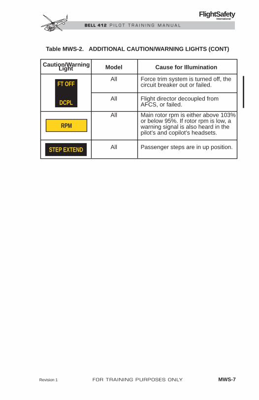
Revision 1 FOR TRAINING PURPOSES ONLY MWS-7
FlightSafety International
BELL 412 P I L O T T R A I N I N G M A N U A L
Table MWS-2. ADDITIONAL CAUTION/WARNING LIGHTS (CONT)
Caution/Warning Model Cause for Illumination Light
All Force trim system is turned off, the circuit breaker out or failed.
All Flight director decoupled from AFCS, or failed.
All Main rotor rpm is either above 103% or below 95%. If rotor rpm is low, a warning signal is also heard in the pilot’s and copilot’s headsets.
All Passenger steps are in up position.STEP EXTEND
RPM
FT OFF
DCPL

MWS-8 FOR TRAINING PURPOSES ONLY
FlightSafety International
BELL 412 P I L O T T R A I N I N G M A N U A L
RESET
TEST
BRIGHT
DIM
+
OIL PRESSURE
DC GENERATOR
PART SEP OFF
FUEL BOOST
FUEL FILTER
FUEL LOW
GOV MANUAL
CHIP
FUEL VALVE
GEN OVHT
DC GENERATOR
PART SEP OFF
FUEL BOOST
FUEL FILTER
FUEL LOW
GOV MANUAL
CHIP
FUEL VALVE
GEN OVHT
CAUTION PANEL
OIL PRESSURE
XMSN OIL PRESS C BOX OIL PRESS
C BOX OIL TEMPXMSN OIL TEMP
BATTERY TEMP
ROTOR BRAKE
ROTOR BRAKE
CHIP C BOX
INVERTER #1 INVERTER #2CHIP XMSN
CHIP 42/90 BOX
EXTERNAL POWER FUEL XFEED
DOOR LOCK HEATER AIR LINE
BATTERY AFCS
ENG2
ENG1
HYDRAULIC
Figure MWS-01. ANNUNCIATORS—SNs 33001–33107

FOR TRAINING PURPOSES ONLY MWS-9
FlightSafety International
BELL 412 P I L O T T R A I N I N G M A N U A L
ENG1
ENG2
TEST RESET
PNL BRT
LT DIM
OILPRESSURE
ENGINECHIP
FUELVALVE
NO. 1 FUELBOOST
NO. 1 GENOVHT
XMSN OILPRESSURE
XMSN OILTEMP
XMSNCHIP
42/90 BOXCHIP
PART SEPOFF
GOVMANUAL
DCGENERATOR
PART SEPOFF
GOVMANUAL
DCGENERATOR
AFCS C'BOX OILPRESSURE
C'BOX OILTEMP
ROTORBRAKE
C BOXCHIP
NO. 1HYDRAULIC
NO. 2HYDRAULIC
CAUTIONPANEL
DOORLOCK
NO. 2INVERTER
EXTERNALPOWER
NO.1INVERTER
HEATERAIR LINE
NO. 1 FUELTRANS
NO. 1 FUELFILTER
FUELLOW
BATTERYTEMP
OILPRESSURE
ENGINECHIP
FUELVALVE
NO. 2 FUELBOOST
NO. 2 FUELTRANS
NO. 2 FUELFILTER
FUELINTCON
FUELXFEED
BATTERY
NO. 2 GENOVHT
ROTORBRAKE
+
Figure MWS-02. ANNUNCIATORS—SNs 33108 AND SUBSEQUENT
Figure MWS-03. ANNUNCIATORS—SNs 36087 AND SUBSEQUENT
ENG1
ENG2
RESET
TESTPNL BRT
LT DIM
OILPRESSURE
ENGINECHIP
FUELVALVE
NO. 1 FUELBOOST
NO. 2 EFISFAN
XMSN OILPRESSURE
XMSN OILTEMP
XMSNCHIP
42/90 BOXCHIP
CLTV
PART SEPOFF
GOVMANUAL
DCGENERATOR
PART SEPOFF
GOVMANUAL
DCGENERATOR
NO. 1 AUTOPILOT
C'BOX OILPRESSURE
C'BOX OILTEMP
ROTORBRAKE
NO.1EFIS FAN
C'BOXCHIP
NO. 1HYDRAULIC
NO. 2HYDRAULIC
CAUTIONPANEL
DOORLOCK
AUTOTRIM
NO. 2INVERTER
EXTERNALPOWER
NO.1INVERTER
HEATERAIR LINE
NO. 1 FUELTRANS
NO. 1 FUELFILTER
FUELLOW
FDR SYSFAIL
BATTERYTEMP
OILPRESSURE
ENGINECHIP
FUELVALVE
NO. 2 FUELBOOST
NO. 2 FUELTRANS
NO. 2 FUELFILTER
FUELINTCON
FUELXFEED
BATTERY
NO. 1 AUTOPILOT
ROTORBRAKE

SYSTEMS REVIEW
CONTENTSPage
INTRODUCTION ............................................................................. SR-1
HELICOPTER DESCRIPTION........................................................ SR-1
Principal Dimensions ............................................................... SR-1
Location References................................................................. SR-1
GENERAL ARRANGEMENT......................................................... SR-5
Crew Compartment .................................................................. SR-5
Passenger/Cargo Compartment................................................ SR-5
Baggage Compartment............................................................. SR-6
INSTRUMENT PANEL AND CONSOLES..................................... SR-7
ROTOR SYSTEMS ........................................................................... SR-7
Main Rotor ............................................................................... SR-7
Tail Rotor ................................................................................. SR-7
TRANSMISSION.............................................................................. SR-8
HYDRAULIC SYSTEMS................................................................. SR-9
FLIGHT CONTROL SYSTEM ........................................................ SR-9
FORCE TRIM SYSTEM ................................................................ SR-10
Force Trim Controls............................................................... SR-10
PITOT-STATIC SYSTEM............................................................... SR-10
AUXILIARY SYSTEMS ................................................................ SR-11
Heating Systems..................................................................... SR-11
Ventilating Systems ............................................................... SR-11
Lighting Systems ................................................................... SR-11
Windshield Wipers................................................................. SR-12
Intercommunications Systems ............................................... SR-12
Rotor Brake............................................................................ SR-12
EMERGENCY EQUIPMENT ........................................................ SR-13
Fire Detection System............................................................ SR-13
Revision 1 FOR TRAINING PURPOSES ONLY SR-i
FlightSafety International
BELL 412 P I L O T T R A I N I N G M A N U A L

Engine Fire Extinguishing System ........................................ SR-13
Portable Fire Extinguishers.................................................... SR-13
First Aid Kit ........................................................................... SR-13
Emergency Exits .................................................................... SR-13
SR-ii FOR TRAINING PURPOSES ONLY
FlightSafety International
BELL 412 P I L O T T R A I N I N G M A N U A L

ILLUSTRATIONSFigure Title Page
SR-1 Principal Dimensions ....................................................... SR-2
SR-2 Transmission Oil System Schematic ............................. SR-8
FOR TRAINING PURPOSES ONLY SR-iii
FlightSafety International
BELL 412 P I L O T T R A I N I N G M A N U A L

SYSTEMS REVIEW
INTRODUCTIONThe helicopter, its primary and auxiliary systems, and emergency equipmentare described within this section.
HELICOPTER DESCRIPTIONThe Bell Helicopter Textron Model 412 is a twin-engine, fifteen-place heli-copter with a single four-bladed main rotor system and a tail rotor to providedirectional control.
The airframe is a semimonocoque structure with metal and fiberglass cover-ing. Two longitudinal main beams and the pylon support structure provide pri-mary support.
Skid-type landing gear is affixed below the fuselage. Optional skid-mountedemergency pop-out flotation gear is available.
PRINCIPAL DIMENSIONSPrincipal exterior dimensions are shown in Figure SR-1. All height dimen-sions must be considered approximate due to variations in loading and alight-ing gear deflection.
LOCATION REFERENCESLocations on and within the helicopter can be determined in relation to fuse-lage stations, waterlines, and buttock lines, measured in inches from knownreference points.
Fuselage StationsFuselage stations (FS or sta.) are vertical planes perpendicular to, and mea-sured along, the longitudinal axis of the helicopter. Station zero is the ref-erence datum plane and is 20 inches (508 millimeters) aft of the nose ofthe helicopter.
WaterlinesWaterlines (WL) are horizontal planes perpendicular to, and measured along,the vertical axis of the helicopter. Waterline zero is a reference plane located7.4 inches (188 millimeters) below the lowest point of the fuselage.
FOR TRAINING PURPOSES ONLY SR-1
FlightSafety International
BELL 412 P I L O T T R A I N I N G M A N U A L

FlightSafety
International
BE
LL 4
12
P
ILO
T T
RA
ININ
G M
AN
UA
L
SR
-2FO
R T
RA
ININ
G P
UR
PO
SES
ON
LY
2 FT 7 IN.(777 MM)
9 FT 4 IN.(2.8 M)
4 FT 8 IN.(1.4 M)
12 FT 1.2 IN.(4.0 M)
4 FT 7 IN.(1.4 M)
1 FT 2 IN.(360 MM)
46 FT(14 M)
Figure SR-1. Principal Dimensions (Sheet 1 of 3)

FlightSafety
International
BE
LL 4
12
P
ILO
T T
RA
ININ
G M
AN
UA
L
FO
R T
RA
ININ
G P
UR
PO
SES
ON
LY
SR
-3
6 FT 8 IN.(2.0 M)
9 FT 4 IN.(2.8 M)
NOTES:VERTICAL DIMENSIONS ARE FOR HELICOPTERS AT 11,900 POUNDS (5,262 KILOGRAMS)GROSS WEIGHT. VERTICAL DIMENSIONS WILLINCREASE APPROXIMATELY 3.3 INCHES(83.8 MILLIMETERS) WHEN HELICOPTER IS EMPTY.
Figure SR-1. Principal Dimensions (Sheet 2 of 3)
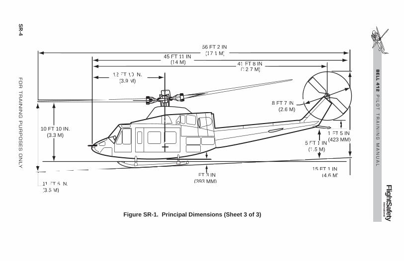
FlightSafety
International
BE
LL 4
12
P
ILO
T T
RA
ININ
G M
AN
UA
L
SR
-4FO
R T
RA
ININ
G P
UR
PO
SES
ON
LY
56 FT 2 IN.(17.1 M)
45 FT 11 IN.(14 M) 41 FT 8 IN.
(12.7 M)12 FT 10 IN.
(3.9 M)
10 FT 10 IN.(3.3 M)
11 FT 5 IN.(3.5 M)
1 FT 3 IN.(393 MM)
15 FT 1 IN.(4.6 M)
5 FT 1 IN.(1.5 M)
1 FT 5 IN.(423 MM)
8 FT 7 IN.(2.6 M)
Figure SR-1. Principal Dimensions (Sheet 3 of 3)

Buttock LinesButtock lines (BL) are vertical planes perpendicular to, and measured to theleft and right along the lateral axis of the helicopter. Buttock line zero is theplane at the longitudinal centerline of the helicopter.
GENERAL ARRANGEMENTThe fuselage forward section contains the nose compartment for electrical andavionics equipment, the crew compartment, the passenger/cargo compartment,and the lower fuel cells. The center section incorporates the transmission com-partment, the pylon support structure, and the upper fuel cells. The aft sec-tion of the fuselage houses the left and right engines, the combining gearboxand oil coolers, and has compartments for avionics, AFCS computers, the bleed-air heater, and optional equipment components.
The tailboom is attached to the aft end of the fuselage and supports the tailrotor and drive train, vertical fin, horizontal stabilizer/elevator, and tail skid.A baggage compartment is located in the forward end of the tailboom.
CREW COMPARTMENTThe crew compartment or cockpit occupies the forward part of the cabin. Thepilot station is on the right side, and the copilot/forward passenger station ison the left.
The instrument panel extends across the front of the cockpit and is tilted up-ward slightly for more direct viewing of the instruments. An overhead con-sole is centered on the cabin roof, and a floor-mounted pedestal is locatedbetween the crew seats.
A door on either side permits direct access to the crew compartment. Largeglass windshields and clear acrylic windows in the crew doors, roof, and lowernose area allow good visibility from the crew compartment.
Crew SeatsThe pilot and copilot seats are designed for energy attenuation to absorb ver-tical impact loads in the event of a hard landing. Adjustment handles locatedbeneath the right side of each seat can be pulled to adjust seats 4.0 inches (10.2centimeters) vertically and 4.5 inches (11.4 centimeters) longitudinally. Eachcrew seat is equipped with a lap seatbelt and a dual shoulder harness with in-ertial reel, which locks in the event of rapid deceleration.
PASSENGER/CARGO COMPARTMENTThe aft area of the cabin contains a space of 220 cubic feet (6.2 cubic meters)for the carriage of passengers or internal cargo.
FOR TRAINING PURPOSES ONLY SR-5
FlightSafety International
BELL 412 P I L O T T R A I N I N G M A N U A L

Thirteen passengers can be accommodated when the optional passenger seatkit is installed.
A large sliding door and a hinged panel on either side of the cabin providefull, direct access to the passenger/cargo compartment. Large acrylic windowsin the doors allow outside viewing from any seat.
Passenger SeatsThe passenger seats are arranged in a row of four seats facing aft, another rowof five seats facing forward, and a pair of seats facing outboard from eitherside of the pylon support structure. All seats are equipped with lap seatbelts,shoulder harnesses, and inertial reels, and are designed for energy attenua-tion to absorb vertical impact loads in the event of a hard landing.
Tiedowns and Equipment FittingsFifty-five tiedown rings and eighty-nine studs are recessed into the cabin deckfor securing internal cargo, passenger seats, and other optional equipment kits,such as internal hoists, litters, etc. Fourteen additional studs are incorporatedinto the cabin roof for attachment of optional equipment.
The deck-mounted tiedown fittings have an airframe structural capacity of1,250 pounds (567.0 kilograms) vertical and 500 pounds (226.8 kilograms)horizontal per fitting.
Provisions for installation of cargo tiedown fittings are incorporated in theaft cabin bulkhead and transmission support structure. Each tiedown point hasan airframe structural capacity of 1,250 pounds (567.0 kilograms) at 90 de-grees to the bulkhead and 500 pounds (226.8 kilograms) in any direction par-allel to the bulkhead.
BAGGAGE COMPARTMENTThe baggage compartment is located in the forward end of the tailboom andhas a capacity of 28 cubic feet (0.8 cubic meter). The compartment can carryup to 400 pounds (181 kilograms) of baggage or other cargo, which can besecured using the twenty tiedown fittings provided.
The access door is on the right side of the tailboom and is provided with akey lock for security of baggage compartment contents.
Two interior lights illuminate the baggage compartment when the door is open.The DOOR LOCK caution light illuminates on the caution panel when the dooris not properly latched.
A smoke detector is installed in the compartment and is connected to the BAG-GAGE FIRE warning light on the instrument panel.
SR-6 FOR TRAINING PURPOSES ONLY
FlightSafety International
BELL 412 P I L O T T R A I N I N G M A N U A L

INSTRUMENT PANEL AND CONSOLESThe instrument panel, which consists of three separate sections, extendsacross the front of the cockpit. It is tilted slightly to provide better viewingof the instruments by the flight crew.
The flight instruments are mounted in the section in front of the pilot’s seat.The system’s instruments and the caution panel are mounted in the centersection of the panel. Optional copilot flight instruments are mounted in thesection in front of the left seat.
The collective control panel mounts engine switches used during starting andshutdown, landing light and searchlight control switches, and optionalequipment switches.
The pedestal, located between the two crew seats, supports the avionics con-trol heads, and engine and flight control system switches. A case for stowageof the helicopter logbook, maps, and other data is incorporated into thepedestal.
The hourmeter panel is located at the base of the pedestal on the right side.It supports the hourmeter, transmission chip indicators (XMSN CHIP IND),and the battery bus circuit breakers (NO. 1 BUS BAT and NO. 2 BUS BAT).The hourmeter records aircraft operating time in hours and tenths. The trans-mission chip indicators provide an indication to maintenance personnel thatthe transmission chip caution light (XMSN CHIP) had illuminated and wherethe chip occurred. To reset the indicator, rotate the outer portion 60 degreesclockwise.
The Dual Digital AFCS EEPROM READ and ERASE switches are locatedon the console just aft of the hourmeter panel.
The overhead console mounts electrical system switches and circuit breakers.
ROTOR SYSTEMSMAIN ROTORThe main rotor system consists of four composite blades mounted to flex-beamtype yokes to provide a soft-in-plane arrangement. Elastomeric bearings helpdamp vibrations and provide lead-lag action for the main rotor blades. Twoof the blades can be folded parallel to the others to minimize the space re-quired for storage.
TAIL ROTORThe tail rotor is a two-bladed, semi-rigid rotor system mounted on the rightside of the vertical fin. Rotor flapping is allowed by a delta hinge for stabil-ity during hovering turns and forward flight.
Revision 1 FOR TRAINING PURPOSES ONLY SR-7
FlightSafety International
BELL 412 P I L O T T R A I N I N G M A N U A L

TRANSMISSIONThe transmission is mounted in the pylon support structure with four vibra-tion-isolating mounts. Two stages of planetary reduction gears and spiral bevelgears are used to reduce the input driveshaft speed to the speeds required formain rotor and tail rotor drive. Both hydraulic pumps are driven by the trans-mission (Figure SR-2).
A gage in the instrument panel allows the flight crew to monitor transmis-sion oil temperature and pressure. Warning lights are provided to warn of hightransmission oil temperature and low transmission oil pressure. A caution lightis provided to warn of metal particles in transmission oil. Three remote trans-mission chip indicators are located on the right side of the pedestal near thecabin floor. On some models a fourth chip detector indicator is connected toa debris monitor which is located in the transmission internal filter.
SR-8 FOR TRAINING PURPOSES ONLY Revision 1
FlightSafety International
BELL 412 P I L O T T R A I N I N G M A N U A L
°C PSIOIL
T PX10
5
0
–5
1015 10
8
6
4
20
TEMPBYPASS
VALVE
COOLER
FILTER
FULL
LOW
PUMP SCREEN
CHIPDETECTOR
JET 4FILTER
INPUTQUILL
JET 5JET 6
CHIPDETECTOR
CHIPDETECTOR
JET 8
VENTPRESS
SW
PRESSXMTR
JET 1
JET 2 (AND TWOAUXILIARY JETS)
JET 7
TEMP SW
RELIEFVALVE
TEMP BULB
JET 3FILLER
CAUTION PANEL
XMSN OIL PRESS
CAUTION PANEL
XMSN OIL HOTTEMP
INDPRESSIND
CAUTION PANEL
CHIP XMSN
LEGEND
NOTE Debris Monitor on HP/EP only.
OIL SUPPLY
PRESSURE
DRAIN
QUICK DISC.
VALVE
UPPER
MAST
PLNTY
TO RESETROTATE
RING60° CW
XMSN
CHIP
IND
PUMP
SUMP
DEBRIS
Figure SR-2. Transmission Oil System Schematic

HYDRAULIC SYSTEMSTwo separate hydraulic systems are used to assist cyclic, collective, and anti-torque flight controls. Each system contains a reservoir, a pump, an integratedvalve and filter assembly, an accumulator, and check valves.
Each integrated valve and filter assembly contains a system pressure filter anda system return filter. In the event any one of these filters becomes partiallyclogged, a button on the filter housing will pop out to give an indication offilter bypass. This button will also activate a switch which will cause a re-mote hydraulic filter bypass indicator in the lower right area of the nose toswitch from green to red. The remote bypass indicator can be seen on the pre-flight check through the lower right nose window.
An electrical interlock prevents both hydraulic systems from being switchedoff at the same time. If one system is off and the second system is switchedoff, the second system will remain on.
The hydraulic pumps are driven by the transmission and have different ratedcapacities. The system 1 pump delivers a greater volume of fluid to operatethe antitorque flight control servoactuator.
The cyclic and collective flight control servoactuators are each powered byboth hydraulic systems, such that if either system fails, the remaining sys-tem will operate the actuators. The antitorque servoactuator is powered bythe No. 1 hydraulic, only.
Each hydraulic system has a gage to allow the flight crew to monitor fluidpressure and temperature. A HYDRAULIC caution light illuminates in theevent of low hydraulic fluid pressure or high temperature in either system.
FLIGHT CONTROL SYSTEMThe flight control system consisting of cyclic, collective pitch, and anti-torque controls, is used to regulate helicopter attitude, altitude, and directionof flight. The flight controls are hydraulically boosted to reduce pilot effort,to overcome resistance of the elastomeric bearings in the main rotor system,and to counteract control feedback forces.
Control inputs from the cyclic stick, collective stick, and antitorque pedalsare transmitted by push-pull tubes and bellcranks to the hydraulic flight con-trol actuators. The two cyclic flight control actuators are connected to the swash-plate, located above the transmission. The swashplate converts the fixedcontrols to rotating controls and actuates alternating cyclic pitch inputs to themain rotor.
The collective flight control actuator is connected to the collective lever atthe mast. The collective lever actuates the collective sleeve, which moves themixing/rephasing levers up and down to induce collective pitch to the blades.
The antitorque flight control actuator is located in the aft fuselage compart-ment near the tailboom attachment. The tail rotor fixed controls are connected
Revision 1 FOR TRAINING PURPOSES ONLY SR-9
FlightSafety International
BELL 412 P I L O T T R A I N I N G M A N U A L

to the rotating controls through a bearing in the crosshead assembly, whichslides along the tail rotor mast to provide pitch change control.
The antitorque control pedals in the cockpit can be adjusted fore and aftby depressing and rotating a knob located on the floor just forward of eachcrew seat.
FORCE TRIM SYSTEMThe cyclic and antitorque controls incorporate a force trim system to provideartificial control reaction forces when the controls are manually moved fromtheir reference positions. The force trim system is also interrelated with theoperation of the AFCS. Refer to Automatic Flight Control System.
The force trim components include spring-loaded force gradient cartridgesconnected in a series with the rotary trim actuators to the fore/aft and lateralcyclic controls and to the antitorque controls. When engaged, the trim actu-ators become locked in position by internal magnetic brakes. Manual move-ment of the controls then actuates the force gradients which provide thedesired control resistance.
FORCE TRIM CONTROLSThe force trim system is activated by the FORCE TRIM switch, located onthe pedestal. A FORCE TRIM release button, located on the cyclic stick grip,can be depressed to de-energize the system momentarily, allowing the pilotto reposition the cyclic and pedals for long term pitch, roll, and yaw correc-tions. Upon releasing the button, the magnetic brakes are re-energized andwill lock the trim actuators in the new reference positions existing at the mo-ment the button is released.
The pilot cyclic control stick is gimbal mounted to provide movement in anydirection. There are two cyclic centering caution lights located on the pilot’sand copilot’s instrument panel near the MASTER CAUTION light. These lightswill illuminate upon excessive cyclic inputs during ground operations belownormal operating range. Properly positioning the cyclic stick will extinguishthe lights.
PITOT-STATIC SYSTEMThe pitot system consists of an electrically heated pitot tube connected to theairspeed indicator. A second, independent pitot system is installed when theoptional copilot’s instrument kit is installed.
The static system consists of the static ports and the tubing necessary to con-nect them to the airspeed indicator(s), altimeter(s), and vertical speed indi-cator(s). Two static ports are located just forward of the crew doors. IFRconfigured helicopters are equipped with heated static ports. Two additionalstatic ports are located on the roof underneath the transmission cowling.
SR-10 FOR TRAINING PURPOSES ONLY Revision 1
FlightSafety International
BELL 412 P I L O T T R A I N I N G M A N U A L

An alternate static port (if installed) is located inside the cockpit on thepilot’s instrument panel on back of the STATIC SOURCE switch. Undernormal conditions, the switch should be placed in the PRI position. Thisposition selects the static ports located forward of the crew doors as wellas the roof mounted static ports (if installed). If erratic readings areseen on the airspeed indicator, altimeter, and vertical speed indicators,obstruction of the outside static ports is a possible cause. If this occurs,the STATIC SOURCE switch should be placed in the ALTN position. Thisposition selects the alternate static air source (cabin air) and at the sametime, shuts off the outside static air source for the pilot’s side only.
AUXILIARY SYSTEMSHEATING SYSTEMThe cabin heating system, which includes the windshield defrost system,uses bleed air from the engine compressor sections as the source of heat. Amixing valve which is controlled by a thermostat, mixes heated air with out-side air to obtain the desired temperature.
When windshield defrost is selected, heated air is diverted from the doorpostand pedestal heater outlets to the windshield nozzles.
VENTILATING SYSTEMThe ventilating system delivers outside air to nozzles by the instrument paneland also to the windshield nozzles to defog the windshield and provide freshair ventilation. The overhead ventilation system delivers outside air throughoverhead nozzles to the crew and passenger compartments.
LIGHTING SYSTEMS
Interior LightingTwo multipurpose cockpit/map lights are mounted overhead in the crew com-partment. Either the white or red light can be selected and the lights may beadjusted from spot beam to flood type illumination. These lights may be re-moved from their mounts for increased utility.
Three dome lights with intensity adjustments are mounted in the passengercompartment. The dome lights also illuminate either red or white and are con-trolled by a switch and rheostat located in the overhead console.
Two lights in the baggage compartment are automatically switched on whenthe door is opened.
Other interior lighting circuits include the instrument panel lights, instrumentsecondary lights, overhead console lights, and pedestal lights all controlledby rheostats in the overhead console. An approach plate and map light is lo-cated on each forward crew doorpost and is controlled by a rheostat knob onthe instrument panel.
Revision 1 FOR TRAINING PURPOSES ONLY SR-11
FlightSafety International
BELL 412 P I L O T T R A I N I N G M A N U A L

Four self-illuminating beta lights are mounted over the windows in the pas-senger/cargo doors to identify the emergency exits.
Exterior LightingExterior lighting circuits include position lights, anticollision lights, a land-ing light, a searchlight, and utility (step) lights. The landing light and search-light are controlled by switches on the pilot’s collective stick. The otherexterior lights are controlled by switches in the overhead console.
WINDSHIELD WIPERSElectrically powered windshield wipers are mounted above the windshields.Selector knobs on the overhead console allow the pilot and copilot to controlthe windshield wipers independently.
INTERCOMMUNICATIONS SYSTEMThe intercommunications control panel(s), located on the pedestal, are usedby the flight crew to control the intercom system and the navigation and com-munication radio signals.
An optional aft intercom system may be installed to enable the flight crew tocommunicate with passengers in the aft cabin in response to illumination ofthe AFT INT CALL lights on the instrument panel. Passengers may also usethe aft intercom system to communicate with each other, or to monitor othercommunication or navigation systems being used by the flight crew. DuringIFR operations it is recommended that AFT INT be left off to preclude in-terference with air traffic control communications.
ROTOR BRAKEThe rotor brake incorporates dual hydraulic systems which are independentof the flight control hydraulic systems. The primary components include adual master cylinder located on the forward cabin roof, a brake disc with dualbrake cylinders mounted on the transmission, and associated hydraulic tub-ing. Two ROTOR BRAKE warning lights on the caution panel are activatedby pressure switches in the brake hydraulic systems to warn the pilot that thebrake is not fully released.
Rotor brake application is limited to ground operation after both engineshave been shut down and rotor rpm has decreased to 40%. The brake shouldbe released just before the rotor stops to preclude backlash, and the brakehandle should be returned to the full-up detent position. After securing themain rotor blades, the rotor brake may be locked to stabilize the rotor dur-ing windy conditions.
SR-12 FOR TRAINING PURPOSES ONLY Revision 1
FlightSafety International
BELL 412 P I L O T T R A I N I N G M A N U A L

EMERGENCY EQUIPMENTFIRE DETECTION SYSTEMA set of heat sensing elements is mounted to the cowling and forward fire-wall for each power section. A fire or overheat condition will cause the FIREPULL handle for the affected power section to illuminate.
A smoke detector is mounted at the forward end of the baggage compartmentceiling. Smoke in the baggage compartment will cause the BAGGAGE FIREwarning light in the instrument panel to flash intermittently.
ENGINE FIRE EXTINGUISHING SYSTEMA fire extinguisher bottle for each power section is mounted in the aft fuse-lage. These bottles are connected in such a way as to allow either bottle to bedischarged onto either engine. Pulling the FIRE PULL handle of the affectedpower section closes the bypass door in the air management system, closesthe fuel shutoff valve, closes both heater bleed-air valves, and arms both firebottles. The fire extinguisher selector switch may then be used to dischargethe main and reserve fire extinguisher bottles individually.
PORTABLE FIRE EXTINGUISHERSTwo portable fire extinguishers are mounted in the cabin, one on the cabinfloor to the right of the pilot’s seat, and the other on the doorpost aft of thecopilot’s seat.
FIRST AID KITA portable first aid kit is attached to the left side of the pedestal by hook andpile fasteners.
EMERGENCY EXITS
Door JettisonIf crew doors will not open, door jettison can be accomplished by pulling thejettison handles, located on the doorpost forward of each crew door.
Window JettisonIf cabin sliding doors or hinged panels cannot be opened, emergency escapeis possible by pushing on the corners of the windows in the sliding doors tojettison the windows.
FOR TRAINING PURPOSES ONLY SR-13
FlightSafety International
BELL 412 P I L O T T R A I N I N G M A N U A L

FlightSafetyInternational
BELL 412 P I L O T T R A I N I N G M A N U A L
SYSTEMS REVIEW—412SP
CONTENTSPage
POWERPLANT........................................................................... SR-SP-5FUEL SYSTEM........................................................................... SR-SP-5
Description—Mechanical................................................... SR-SP-5Description—Electrical .................................................... SR-SP-10
ELECTRICAL SYSTEM .......................................................... SR-SP-16DC Electrical System ....................................................... SR-SP-16AC Electrical System ....................................................... SR-SP-18
HYDRAULIC SYSTEM ........................................................... SR-SP-18FLIGHT CONTROL SYSTEM................................................. SR-SP-19
Force Trim Systems.......................................................... SR-SP-20AUTOMATIC FLIGHT CONTROL SYSTEM (AFCS)........... SR-SP-20
AFCS Controls and Indicators ......................................... SR-SP-21PITOT-STATIC SYSTEM ......................................................... SR-SP-23AUXILIARY SYSTEMS........................................................... SR-SP-23
Heating System ................................................................ SR-SP-23Ventilating System............................................................ SR-SP-23Lighting Systems.............................................................. SR-SP-24Windshield Wipers ........................................................... SR-SP-24Intercommunications Systems.......................................... SR-SP-24Rotor Brake ...................................................................... SR-SP-25
EMERGENCY EQUIPMENT................................................... SR-SP-25Fire Detection................................................................... SR-SP-25Engine Fire Extinguishing System................................... SR-SP-25First Aid Kit ..................................................................... SR-SP-26Emergency Exits............................................................... SR-SP-26
Revision 1 FOR TRAINING PURPOSES ONLY SR-SP-i

FlightSafetyInternational
BELL 412 P I L O T T R A I N I N G M A N U A L
ILLUSTRATIONSFigure Title PageSR-SP-1 Instrument Panel ....................................................... SR-SP-1SR-SP-2 Overhead Console..................................................... SR-SP-2SR-SP-3 Pedestal ..................................................................... SR-SP-3SR-SP-4 Hourmeter Panel ....................................................... SR-SP-4SR-SP-5 Airframe Fuel Storage Systems
(SNs 33108–33167)................................................... SR-SP-6SR-SP-6 Fuel Transfer Pump Operation
(SNs 33168 and Subsequent).................................... SR-SP-7SR-SP-7 Fuel Burn Sequence .................................................. SR-SP-9SR-SP-8 Fuel Transfer Caution Light Diagram .................... SR-SP-12SR-SP-9 Electrical System .................................................... SR-SP-13
TABLESTable Title PageSR-SP-1 Essential Bus Failure Listing.................................. SR-SP-14SR-SP-2 Emergency Bus Failure Listing .............................. SR-SP-15
Revision 1 FOR TRAINING PURPOSES ONLY SR-SP-iii

SYSTEMSREVIEW
—412SP FlightSafety
International
BE
LL
41
2P
ILO
TT
RA
ININ
GM
AN
UA
L
FO
RTR
AIN
ING
PU
RP
OS
ES
ON
LY
SR-SP-1 Figure SR-SP-1. Instrument Panel

FlightSafetyInternational
BELL 412 P I L O T T R A I N I N G M A N U A L
SR-SP-2 FOR TRAINING PURPOSES ONLY
NON-ESSENTIALBUSESSENTIALBUSEMERGENCYBUS
LEGEND
ENGINE NO 1
XFEED
FUEL
CONTR
FUEL
TRANS
FUEL
CONTRHTR
FUEL
BOOST
FUEL
INT CON
FUEL
QTY
FUEL
VALVE
FUEL
CAUTION/WARNINGHYD
RPM
BAGCOMPT
SYS
NO 1
TEMP
NO 1 ENG 1
CAUTION
MASTER
DET
ENG 1FIRE
FIRE EXT
MAINFIRE
TEMP
CBOXOIL
SEP
PART
RESET
GEN 1
CPLT
ICSITT
COMP
IGN
RLY
STARTPITOTHTR
FIELD
GEN 1 NO 2 ESNTL NO 1 ESNTL
BUSFEEDERS
BUSFEEDERS
PWR
INV 1
WIPERCPLT
WINDSHIELD
CONTR
GOV
BCN
MKRIDLEICS
CABIN STOPCPLT
TURNSLIP
COMM
VHF 1NAV 1DME
ADF
LF
SEC
INST
POS CSL
LIGHTING
PED PWR
LDG
CONTR
LDG
CPLT
MAP
CPLT
INST
NO 2PRESS
NO 1HYD
HSI
CPLT
PRESS
FUEL
PRESS
OIL
METER
TORQUE
NO 2
AFCS115V
VM
BUS 1
HSI
CPLT
CMPS
CPLTGYRO
REL
CARGOHOOK
SYS
CPLTATT
NAV-COMM
ACENG 1 ENG 2
MAIN DC
XFEED
FUEL
TRANS
FUEL
CONTRHTR
FUEL
BOOST
FUEL
INTCON
FUEL
QTY
FUEL
VALVE
FUEL
CONTR
FUEL
CAUTION/WARNING
RPM
ENG 2
RPM
ROTOR
SYS
NO 2
TEMP
NO 2
FAIL
CAUTION
EXTG
RESFIRE
DETR
ENG 2FIRE
TEMP
XMSNOIL
SEP
PART
RLY
START
RESET
GEN 2
TEMPPILOT
ICS OIL ITTIGN
PILOT
PITOTHTR
FIELD
GEN 2NO 2 ESNTLNO 1 ESNTL
BUSFEEDERS
BUSFEEDERS
WIPERPILOT
WINDSHIELD
PWR
INV 2
XPDR
IDENT STBY
ATTCOMM
VHF 2 NAV 2 VLF
ALTNAV
RAD
INST
ENG ANTI BAG
COMPTCOLL
LIGHTING
UTILPWR
SCHLT
CONTR
SCHLT
PILOT
MAP
PILOT
INST
NO 1 PRESS
NO 2HYD
HSI
PILOT
PRESSPRESS
FUEL
PRESS
OIL
METER
TORQUEAFCS26V
CBOXOIL
NO 1
PILOTGYRO
VM
BUS 2
HSI
PILOT
CMPS
PILOT115V
SYS DIR
FLTPILOTATT
NAV-COMMAC
AC
AC
MAIN DC
ENGINE
ENGINE NO 2
NO 2
COMP
INICT
EMERGBUS
BUS
NON ESNTL HOUR
METER NO 2
AFCS
EMER
LT
STBYATTDTEST
EMERLT
DISARMLH
OFF
ON ARM
TESTOFF
PWR
WINDSHIELD HEAT
CONT PWRRH
HTR
CABINCONTLH
NO 1
AFCS FORCE
TRIM FLOATS
EMERG
CUT
CABLE
DIR
FLT
AIR VENT CONT
DOME BLO BLO
PWRLT
HOIST
OFF
WHITE
RED
OFF
AIR CONDAIRFLOW
LOW
HIGH
WSHLD HEATRHOFF
ONON
VENTBLOWER
OFF
ON
OFF
UTILITYLIGHT
ON
OFF
EXTERIOR LIGHT
ON
OFF ANTI COLL POSITION
ON
MANUAL
NORMAL
NORMAL
OFF
ON
OFF
INV 2INV 1
EMERG LOAD
NON-ESNTLBUS
ON
AFTOUTLET
OFF
ON
HEATEROFF
ON
CARGORELEASE
OFF
ARMHEAT
WIPERS
PITOT STATICHEATERS
OFF
ON
OFF
PILOT
LO
MED
HI
PK
OFF
COPILOT
LO
MED
HI
PK
AFT DOME LIGHT
PED LT
ENG INSTR LT
OFF BRT
OFF BRT
OFF BRT
SEC INSTR LT
PILOT INSTR LT
OFF BRT
OFF BRT
CONSOLE LT
COPLT INSTR LT
OFF BRT
OFF BRT
RESET
ON
OFF
ONBUS 1
OFF
BATTERY GEN 1
OFF
RESET
ON
GEN 2
ONBUS 2
CPLTTEMP
OIL
ADF
LF
PRESS
XMSNOIL
AFCS26V
STEP
PLT
TURNSLIP
HYD
ENGINE NO 1
115V
BUS 2
25V115V26V
EMERBUS
ACFEEDERS
115V
BUS1 BUS3
26V 115V 26V
ACFEEDERS
Figure SR-SP-2. Overhead Console

FlightSafetyInternational
BELL 412 P I L O T T R A I N I N G M A N U A L
FOR TRAINING PURPOSES ONLY SR-SP-3
MAPANDDATACASE
NAV AUDIO
COMPASS CONTROL
COMM 1 COMM 2
MKR BCN DME
MAG
COMM
ICS
COMM 1
ON
VOLPULLTEST
OFF
COMM 2 NAV 1
NAV 2
ADP MKRMDE
VOL
AUX
DC
VOLVOL
HILOOFF
SENSITIVITY
COMPASS CONTROLMAG
DC
ON
ICS
COMM 1
ON
COMM 2 NAV 1
NAV 2
ADP MKRMDE
VOL
AUX
ON
COMMVOL
PULLTEST
OFF
NAV 1
NAVVOL
OFF
NAV 2
NAVVOL
OFF
VOL
OFF
ADF ANTBFD
X
BFD
XPGA
SBY ON ALT IDT
RFL
ALTON
SBY
OFF
TST
AFCS ACTUATOR POSITION
SYS 2 L R
L R UP
YAW ROLL PITCH
ON
ON
HP 1
ON
CPL
HYDR SYSNO 1
STEP
ON RAISE AUDIO
OFFOFF
ON
OFF
MISC
FUEL
FUEL
TRANS
FUEL
TRANS
BOOST
PUMP
BOOST
PUMP
FUEL
OFF
OFF
ON
STOW
ENGINE 1GOV
AUTO
MANUALFUEL
XFEED/INTCONTEST BUS 1
MANUALOVRD ON OVRD ON
ON
OFF
ON
ON OVRD CLOSE
OVRD CLOSE
ON
ON ON
OFF
OFF OFF
OFF OPEN
FUELINTCONNORM
OFF
NORM
TEST BUS 2
FUEL XFEEDNORM
GOVAUTO
PART SEPNORM
PART SEPNORM
ENGINE 2
ROTORRPM
FORCETRIM
HYDR SYSNO 2
ON
HP 2
SAS/ATTSAS/ATT
AFTTANK
FWDTANK
ENGINE 1
AFTTANK
FWDTANK
ENGINE 2
Figure SR-SP-3. Pedestal
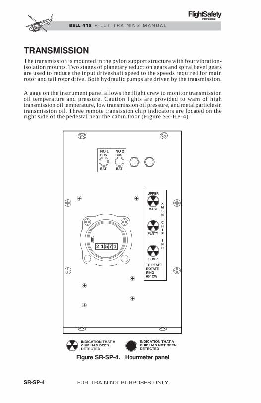
FlightSafetyInternational
BELL 412 P I L O T T R A I N I N G M A N U A L
TRANSMISSIONThe transmission is mounted in the pylon support structure with four vibration-isolation mounts. Two stages of planetary reduction gears and spiral bevel gearsare used to reduce the input driveshaft speed to the speeds required for mainrotor and tail rotor drive. Both hydraulic pumps are driven by the transmission.
A gage on the instrument panel allows the flight crew to monitor transmissionoil temperature and pressure. Caution lights are provided to warn of hightransmission oil temperature, low transmission oil pressure, and metal particlesintransmission oil. Three remote transission chip indicators are located on theright side of the pedestal near the cabin floor (Figure SR-HP-4).
SR-SP-4 FOR TRAINING PURPOSES ONLY
2 1 5 7 1
NO 1BUS
BAT
UPPER
MAST
XMSN
CHIP
IND
PLNTY
SUMP
TO RESETROTATERING60° CW
INDICATION THAT ACHIP HAD BEENDETECTED
INDICATION THAT ACHIP HAD NOT BEENDETECTED
BAT
BUSNO 2
Figure SR-SP-4. Hourmeter panel

FlightSafetyInternational
BELL 412 P I L O T T R A I N I N G M A N U A L
POWERPLANTThe powerplant, a Pratt and Whitney PT6T-3B twin turboshaft engine, con-sists of two identical free-turbine power sections connected to a combin-ing/reduction gearbox. Each power section has its own lubrication system,starter/generator, and fuel control. The combining gearbox has a separatelubrication system.
Instruments on the panel provide indications of gas producer rpm (GASPROD), power turbine rpm (ENG), torque, interturbine temperature, oil tem-perature, and oil pressure for each power section, and oil temperature and oilpressure for the combining gearbox. Caution and warning lights alert the crewof the following conditions: low GAS PROD or ENG rpm, low engine oil pres-sure, metal particles in the engine oil, low combining gearbox oil pressure,high combining gearbox oil temperature, and metal particles in the combin-ing gearbox oil.
FUEL SYSTEMThe fuel system description is in two parts—mechanical and electrical.
DESCRIPTION—MECHANICALThe fuel system (Figure SR-SP-5) is comprised of 10 crash resistant fuel cells.Six of the cells are located below the cabin floor and four are located aft ofthe cabin and above the level of the underfloor cells. A system of transfer pumps,interconnects, and standpipes provides a fuel burn sequence (Figure SR-SP-7) that maintains the fuel C.G. within the required limits. Partial cell dividers(isolation barrier) cells in the upper center main cells,and the system inter-connect valve provide 65.5 gallons (247.9 liters) isolated fuel supply foreach engine.
Cell VentsFour fuel cell vents are located on the underside of the fuselage. The two ventslocated inside of the doorposts vent the lower forward and mid cells. The twovents located aft of the fuel compartment vent the lower main and upperfuel cells.
During refuel operations, air pressure may force some fuel into the vent lines,and it is normal for the system to expel up to a pint of fuel under eachdoorpost.
Fuel Transfer And FillingEach lower fuel cell is joined with its opposite (left and right), and with theupper cells by an interconnect system. Standpipes in the upper cells controlthe fill and burn sequence. Fuel is supplied to the engines from the main un-derfloor cells (engine feed cells). Fuel for sequences 1, 3, and 5 is transferredto the engine feed cells by gravity. Burn 2 and 4 fuel is transferred to the en-
FOR TRAINING PURPOSES ONLY SR-SP-5

FUEL CELLS
FUEL STORAGE SYSTEM COMPONENTS
FUEL QUANTITY PROBES
LEGEND
THERMISTORS
THERMISTOR
THERMISTOR
Figure SR-SP-5. Airframe Fuel Storage System (SNs 33108–33167)
FlightSafetyInternational
BE
LL
41
2P
ILO
TT
RA
ININ
GM
AN
UA
L
SR-SP-6FO
RTR
AIN
ING
PU
RP
OS
ES
ON
LY
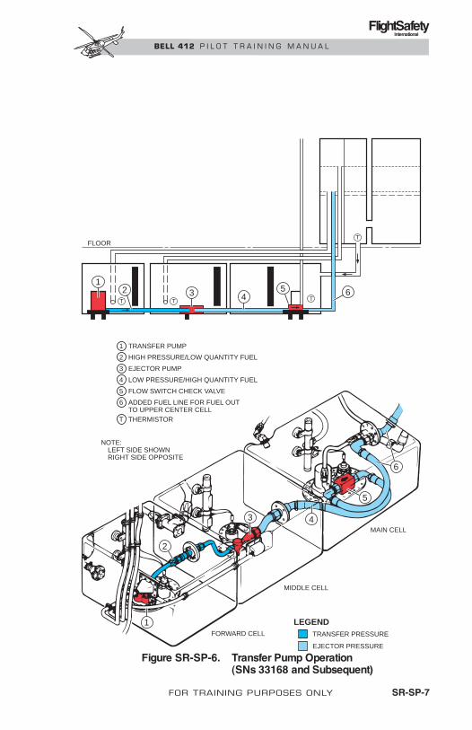
FlightSafetyInternational
BELL 412 P I L O T T R A I N I N G M A N U A L
FOR TRAINING PURPOSES ONLY SR-SP-7
Figure SR-SP-6. Transfer Pump Operation(SNs 33168 and Subsequent)
FLOORT
TTT
12 3 4
5 6
TRANSFER PRESSURE
EJECTOR PRESSURE
LEGEND
NOTE:LEFT SIDE SHOWNRIGHT SIDE OPPOSITE
TRANSFER PUMP1
THERMISTORT
HIGH PRESSURE/LOW QUANTITY FUEL2
EJECTOR PUMP3
LOW PRESSURE/HIGH QUANTITY FUEL4
FLOW SWITCH CHECK VALVE5
ADDED FUEL LINE FOR FUEL OUTTO UPPER CENTER CELL
6
MAIN CELL
MIDDLE CELL
FORWARD CELL
1
4
5
6
3
2

FlightSafetyInternational
BELL 412 P I L O T T R A I N I N G M A N U A L
SR-SP-8 FOR TRAINING PURPOSES ONLY
gine feed cells on helicopter S/N 33167 and prior, and to the upper forwardcenter cell on helicopter S/N 33168 and subsequent by a dual transfer (leftand right) system. Each system consists of an electrically driven transferpump located in the forward underfloor cell, and a combination flow switchand check valve. The transfer system will operate continuously until the burn4 fuel is depleted, then the thermistors located in the forward underfloorcells will shut off the transfer pumps. Fueling through the gravity filler capwill fill the cells in the reverse order of the fuel burn sequence.
A transfer pump in each lower forward tank transfers fuel to the correspondinglower main tank or upper forward center tank. This flow provides the motiveforce for an ejector pump in the lower mid tanks, which transfers fuel fromthat tank to the corresponding lower main tank. The transfer pumps shut offautomatically after the lower forward tanks are emptied.
Engine Feed SystemFuel is supplied to engines by electrically driven boost pumps located in themain underfloor cells (engine feed cells). Fuel passes through a check valveand an electrically operated firewall shutoff valve before entering the engine.A pressure switch for each pump indicates if fuel boost is inoperative. A fuelcrossfeed valve connects the two engine feed systems for operation with oneboost pump inoperative. The crossfeed valve is opened automatically by a sig-nal from the pressure switch when crossfeed switch is in NORM position.
Fuel Quantity SystemFuel quantity is measured by four capacitance-type quantity probes locatedon each side of the helicopter. The signals from these quantity probes are dis-played on a dual needle fuel quantity indicator located in the center instru-ment panel (Figure SR-SP-1). The four quantity probes on the left side of thehelicopter drive one needle and the right four drive the other needle. A digi-tal display on the instrument displays the signal from all eight quantity probes.A DIGITS TEST button is located left of the indicator. When pressed, a prop-erly functioning digital display will read 888. A FWD TANK/MID TANKswitch, located left of the DIGITS TEST button, allows the pilot to check lowerforward and mid cell quantities separately to ensure that proper balance wasmaintained during a shutdown period with partially empty cells. The fuel quan-tity system compensates for the different densities of fuels.
Fuel System ControlsFuel system controls are located on the pedestal mounted engine controlpanel (Figure SR-SP-3). The two transfer pumps and boost pumps are indi-vidually controlled by two-position tank ON/OFF switches. Electrical powerfor No. 1 engine transfer and boost pumps is provided by the No. 1 28 VDCessential bus. Electrical power for No. 2 engine transfer and boost pumps isprovided by the No. 2 28 VDC emergency bus and No. 2 28 VDC essentialbus respectively. Four valve switches are provided: one for each of the fuelvalves, the interconnect valve, and the crossfeed valve. All are two-positionswitches except the FUEL INTCON switch. The normal position of the cross-

FlightSafetyInternational
BELL 412 P I L O T T R A I N I N G M A N U A L
FOR TRAINING PURPOSES ONLY SR-SP-9
Figure SR-SP-7. Fuel Burn Sequence
BURNS 1, 3, AND 5
BURN 2
BURN 6
BURN 4
GR
OS
SW
EIG
HT
—LB
13000
12000
11000
10000
90008800
8000
7000
6000
6400
130 132 134 136 138 140 142 144
T/O CG
AFT LIMIT
LND FUEL0 GAL—0 LB
T/O FUEL330.5 GAL2148 LB
FORWARD LIMIT
LND GW 8925 LB
130.4
135.1 141.4
MINIMUM WEIGHT
LND CG
T/O GW 11073 LB
BURN 111,900 LB
BURN 2
BURN 4BURN 5
BURN 6
BURN 3
BURN 5
FLOOR
BURN 3
BURN 1
BURN 2 BURN 6BURN 4
TT
T

FlightSafetyInternational
BELL 412 P I L O T T R A I N I N G M A N U A L
feed and interconnect valves is closed, but the interconnect valve has an op-tional open position. Both have an override position so the valves may be closed,if necessary, after being automatically opened. Electrical power for the cross-feed valve is provided by the 28 VDC essential buses. Electrical power forthe interconnect valve is provided by the 28 VDC emergency buses. If essentialbus fails, the valves will continue to operate. The fuel valves are powered bythe 28VDC emergency buses. Circuitry protection is provided by circuitbreakers located on the overhead circuit breaker panel. For a more completedescription of the electrical portion of the fuel system, refer to DESCRIP-TION—ELECTRICAL.
DESCRIPTION—ELECTRICALThe electrical portion of this system is basically two distinct parts. One partis fuel quantity indication that is inclusive of the fuel gaging and fuel low levelindication. The other part is the fuel transfer system.
The fuel quantity part of this system is identical for each side of the helicopter,respective to fuel tanks. Fuel quantity system components in each side arefour capacitive fuel probes, a section of the fuel quantity signal conditioner,and one needle of a dual needle indicator. In addition to these componentsare the digital display and the FWD/MID TANK switch function. The digi-tal display, switch function, and probe locations are adequately described inthe mechanical portion of fuel system description.
The probes send information to the signal conditioner, and in turn the signalconditioner processes and sends the information to the indicator.
The low fuel indication that is displayed by a caution segment indicator lightconsists of the caution segment, a part of the signal conditioner, and thermistorson the fuel quantity probe in each outboard upper fuel cell. A thermistor is adevice that changes signal level when fuel is no longer covering it. Thus, thischange in signal level is transmitted to the signal conditioner, which in turnprovides a signal to illuminate the FUEL LOW caution light. Each signal con-ditioner can provide this information to a single FUEL LOW caution light.This means that either outboard upper fuel tanks low fuel condition will re-sult in illuminating the FUEL LOW caution light. The FUEL LOW cautionlight signal from either side is inhibited if electrical power to the respectiveside is not present. This operation is necessary to prevent a signal that is aresult of power failure and not necessarily low fuel.
The fuel low function interacts with a fuel interconnect feature. When bothlow fuel signals from both signal conditioners occur, the fuel interconnect valvewill automatically open between the two engine feed fuel tanks. This will causethe FUEL INTCON caution light to illuminate. The light will extinguishwhen the FUEL INTCON switch is positioned from NORM to OPEN. The op-tion to open or close the interconnect valve is available should a manualoverride be desired from either valve position. When the valve is commandedto change position from the opposite position, by selecting OPEN or OVRDCLOSE, the FUEL INTCON caution light will illuminate during the time ofvalve movement. It will extinguish after the valve reaches a compatible po-sition with the switch. A press-to-test feature is provided to determine if re-
SR-SP-10 FOR TRAINING PURPOSES ONLY

FlightSafetyInternational
BELL 412 P I L O T T R A I N I N G M A N U A L
FOR TRAINING PURPOSES ONLY SR-SP-11
dundant electrical power is available. When the FUEL XFEED/INTCONTEST switch is positioned to TEST BUS 1, the other power source (BUS 2)is disabled. This results in a test that will illuminate the FUEL INTCON cau-tion light if bus 1 electrical power is not available. The same result would bevalid when the switch is positioned to TEST BUS 2. A similar test is simul-taneously performed for the fuel crossfeed circuit by use of this switch.
The transfer part of this system for each side of the helicopter fuel tanks isidentical to the other side. However, the fuel quantity signal conditioner sig-nal that enables the fuel transfer pump is supplied for both fuel transferpumps from either signal conditioner. This results in operation of both fueltransfer pumps until both forward fuel tanks are empty.
Each side has a FUEL TRANS caution light associated with the fuel transferfunction. This light will illuminate if there is fuel in the respective forwardfuel tank and no fuel is being transferred. This condition can occur if the FUELTRANS switches are not positioned to ON and fuel is present in either for-ward tank. Another condition for illumination of this caution light is if fuelshould be present in the mid tank after fuel transfer is complete from the for-ward. This is an indication of trapped, unusable fuel in the mid tank. The lastcondition for illumination of this caution light is loss of power to the respectivefuel quantity signal conditioner and absence of fuel flow from the respectivetransfer pump. This would result in an illuminated FUEL TRANS caution lightwhen the respective fuel quantity indicator is inoperative and fuel transferfrom this forward tank is complete. The light will remain illuminated underthis condition after fuel transfer is complete.
The condition of power loss to the signal conditioner affects the fuel low levelcaution function as previously discussed. The total indication of power lossto a signal conditioner is a loss of fuel quantity indication for the respectiveside and a FUEL TRANS caution light that illuminates and will not extinguishafter fuel transfer from the forward tank is complete.

FlightSafetyInternational
BE
LL
41
2P
ILO
TT
RA
ININ
GM
AN
UA
L
SR-SP-12FO
RTR
AIN
ING
PU
RP
OS
ES
ON
LY
BEFORE FUEL TRANSFER
DURING FUEL TRANSFER
LEGEND
AFTER FUEL TRANSFER
THERMISTOR SWITCHES
SIGNALCONDITIONER
FAILED CHECK VALVE
CLOGGEDEJECTOR PUMP
FAILED TRANSFERPUMP
FUELTRANS
Figure SR-SP-8. Fuel Transfer Caution Light Diagram

FlightSafetyInternational
BELL 412 P I L O T T R A I N I N G M A N U A L
FOR TRAINING PURPOSES ONLY SR-SP-13
NO. 1STARTER
GENERATOR
NO. 2STARTER
GENERATOR
NO. 1STARTRLY
NO. 2STARTRLY
NO. 1GENRLY
EXTPWR RLT NO. 2
GENRLY
NO. 1NON-ESSBUSRLY
NO. 2NON-ESSBUSRLY
NO. 1MAINDC BUS
NO. 1 NONESSDC BUS
NO. 2 NONESSDC BUS
NO. 2MAINDC BUS
NO. 1INVERTER
NO. 2INVERTER
NO. 1 BUSBAT RLY
BAT
BAT BUS
NO. 2 BUSBAT RLY
OVLDSENSOR
OVLDSENSOR
NO. 1VOLTMETER
NO. 1 EMERBUS
NO. 2 EMERBUS
FROMBATBUS
NO. 1 ACVOLT METER
NO. 2 ACVOLT METER
NO. 2VOLT
METER
NO. 1 ESS DC BUS
NO. 1 115-VAC BUS
NO. 2 115-VAC BUS
NO. 3 115-VAC BUS
NO. 2 ESS DC BUS
EMER LOADS SWITCH
DCCONTROL
UNIT
DCCONTROL
UNIT
EXTPWR
LOAD-METER
LOAD-METER
SHUNT SHUNT
Figure SR-SP-9. Electrical System

SYSTEM
Avionics, AFCS, and lighting AFCS 2 inop AFCS, HP 2 off Ess 1
Engine/rotor rpm warning control unit ENGINE OUT light inop None Ess 1/2
Engine systems FCU switch inop None Ess 1/2
Electrical systems Inverter 2 inop INVERTER #2 light Ess 2
Fuel system Fuel boost inop FUEL BOOST light Ess 1/2
Fuel trans 1 inop NO. 1 FUEL TRANS light Ess 1
Hydraulic systems Switch inop None Ess 1/2
Misc and kits Windshield wiper inop None Ess 1/2
Hourmeter inop None Ess 1
Temperature gage inop Gage to 0 Ess 1/2
System on if switch off Pressure up Ess 1/2
DC volts Voltmeter to 0 Ess 1/2Gen reset inop None Ess 1/2
Noness bus inop None Ess 1
FCU to AUTO if MANUAL Eng performance Ess 1/2FCU heater inop None Ess 1/2Ignition inop None Ess 1/2
Starter inop None Ess 1/2RPM inc/dec inop None Ess 1/2Part sep inop PART SEP OFF light Ess 1/2
Temperature gage inop Gage to 0 Ess 1/2
Rotor rpm warning inop None Ess 2
Flight dir inop FD flag Ess 2NAV 1 radio inop No reception Ess 1
C/P ICS inop None Ess 1
C/P turn/slip inop None Ess 1
C/P pitot heater inop None Ess 1
Radar alt inop Off flag Ess 1
Pilot inst lights inop No lights Ess 2Eng inst lights inop No lights Ess 2
Utility light No lights Ess 2
FAILURE INDICATION BUS
R
Fuel XFEED None Ess 1/2
FlightSafetyInternational
BELL 412 P I L O T T R A I N I N G M A N U A L
SR-SP-14 FOR TRAINING PURPOSES ONLY
Table SR-SP-1. ESSENTIAL BUS FAILURE LISTING

Table SR-SP-2. EMERGENCY BUS FAILURE LISTING
FlightSafetyInternational
BELL 412 P I L O T T R A I N I N G M A N U A L
FOR TRAINING PURPOSES ONLY SR-SP-15
Electrical Systems Inverter 1 inop None Emer 1
Inverter 2 inop Inverter 2 Emer 2
SYSTEM
Avionics, AFCS, and lighting VHF 1 COMM inop No xmit or rec Emer 1
Caution panel Caution panel inop CAUTION PANEL light Emer 1
CAUTION PANEL light inop None Emer 2
Emer 2
Fuel system
Engine systems
Misc and kits
Baggage fire detection None Emer 1
C box and xmsn
Pilot turn/slip inop None
Emer 2Pilot map light inop None
Emer 2Pilot pitot heater inop None
Emer 2Stby att ind no charge None
Emer 2Pilot ICS inop None
Emer 2Searchlight inop None
Emer 2Emergency floats inop None
Emer 2Hoist cable cut inop None
Emer 2Passenger step inop None
Emer 1Cargo hook inop HOOK ARMED light off
Emer 1/2Fuel interconnect inop None
Emer 1/2Fuel valve inop FUEL VALVE light
Emer 2Fuel trans 2 inop NO. 2 FUEL TRANS light
Emer 1/2Fuel QTY Gage to 0
Emer 1/2Fire detector inop None
Emer 1/2Fire extinguisher inop None
Emer 1/2ITT compensator inop Gage at 0
Emer 1C box oil temp inop Gage at 0
Emer 2Xmsn oil temp inop Gage at 0
Emer 1/2Engine oil temp inop Gage at 0
Emer 1Idle stop inop None
Emer 2Searchlight control inop None
Emer 2AFCS 1 inop AFCS, HP 1 off
FAILURE INDICATION BUS
Emer 2Force trim FT OFF light
Emer 2Pilot ATT SYS ATT flag

FlightSafetyInternational
BELL 412 P I L O T T R A I N I N G M A N U A L
Caution LightsFuel system caution light segments in the caution panel (Figure SR-SP-1)illuminate to advise the pilot if any of the following conditions exist:
FUEL TRANS No fuel transfer through indicated system. Probablyinoperative transfer or ejector pump.
FUEL BOOST Loss of engine feed line pressure in indicated system.Indicates fuel boost pump failure. Crossfeed valveautomatically opens.
FUEL LOW Fuel level in left or right cells at or below 190 pounds.Interconnect valve will open automatically when fuellevel in opposite side decreases to 190 pounds toallow fuel in lower cells to equalize.
FUEL FILTER Impending bypass of indicated fuel filter resultingfrom contamination and clogging is indicated.
FUEL VALVE Normally illuminated during transit operation, andextinguishes when valve position is same as that ofswitch. A fault is indicated if it does not extinguish.
FUEL XFEED Normally illuminated during transit operation, andextinguishes when valve is seated. A fault is indicatedif it does not extinguish.
FUEL INTCON Normally illuminated during transit operation, andextinguishes when valve is seated in closed positionor indicates valve has automatically opened withswitch in NORM position. Placing the switch in theOPEN position will extinguish the light. A fault is in-dicated if light fails to extinguish.
ELECTRICAL SYSTEMSDC ELECTRICAL SYSTEMThe primary electrical system is a 28-volt direct current, negative groundsystem (Figure SR-SP-9). Power is supplied by two 30-volt, 200-amperestarter/generators, one mounted on each engine. The output voltage of eachgenerator is monitored and regulated by a DC control unit. The DC controlunits provide overvoltage and reverse current protection and control paral-leled generator operation so that the two generators share total loadrequirements within ± 20 amperes.
Each generator supplies power to a main DC bus and to two interconnectednonessential DC buses. Each main DC bus in turn, serves as a feeder for thetwo essential DC buses and two emergency buses. Electrical separationbetween main buses and between generators is accomplished through the useof circuit breakers and isolation diodes.
SR-SP-16 FOR TRAINING PURPOSES ONLY

FlightSafetyInternational
BELL 412 P I L O T T R A I N I N G M A N U A L
In the event that one generator or engine should fail, both nonessential busesare automatically dropped, and all essential and emergency DC loads are sup-plied by the remaining generator. The nonessential bus switch (NON-ESNTLBUS) located on the overhead console (Figure SR-SP-2) is available so thatthe pilot, if desired, can manually restore power to the nonessential buses. Inthe event that the pilot has manually restored power to the nonessential busesand the second generator fails, both nonessential buses are again automati-cally dropped. This arrangement provides automatic DC load shedding (TableSR-SP-2) for a 30-minute flight with electrical power supplied by the bat-tery only.
An emergency load switch is located on the overhead console (Figure SR-SP-2). In the event of dual generator failure, placing the switch in the EMERGLOAD position sheds the essential DC buses providing approximately 90-minutes of flight on battery power only. Placing the switch in the EMERGLOAD position with one or both generators operating does not have any ef-fect on the DC power system. It will, however, affect the AC power system.
The emergency DC buses are energized whenever:
• The emergency load switch is in EMERG LOAD position.
• Either BATTERY switch is ON.
• One or both generators are operating.
• Auxiliary power is provided.
The essential DC buses are energized whenever:
• One or both generators are operating.
• Auxiliary power is provided.
• Either BATTERY switch is on with emergency load switch inNORMAL position.
The nonessential DC buses are energized whenever:
• Both generators are operating.
• Auxiliary power is provided with (NON-ESNTL) inMANUAL position.
• One generator is operating with nonessential bus switch (NON-ESNTL) in MANUAL position.
The primary DC electrical power distribution system is located in the roofand nose of the helicopter. The generator control units, contactors, buses andfeeder protection devices are located beneath the battery, under the lower shelfin the nose compartment. Other contactors, feeder protection devices, andthe distribution buses are located in the cabin roof. System control switchesand distribution circuit breakers are located in the overhead console.
The battery bus switches through the respective battery bus relays prevent aground fault (short) in one main DC bus from disabling both generators.
FOR TRAINING PURPOSES ONLY SR-SP-17

FlightSafetyInternational
BELL 412 P I L O T T R A I N I N G M A N U A L
They also select the generator that charges the battery. During normal oper-ation, BATTERY BUS 2 switch is ON. However, for a battery start of engine1, BATTERY BUS 1 switch must be ON. With both generators or generator2 operating, BATTERY BUS 1 switch will automatically switch to OFF ifBATTERY BUS 2 switch is ON.
AC ELECTRICAL SYSTEMThe AC electrical system (Figure SR-SP-9) consists of two 450-va, 115/26.5-volts, 400 Hz, single-phase, solid state inverters and associated controls.Inverter 1 is energized by emergency DC bus 1 and is controlled by the INV1 switch, located in the overhead console. Inverter 2 is energized by the es-sential DC bus 2 and is controlled by the INV 2 switch, located in the over-head console.
There are four additional components essential to the control and operationof the AC electrical system: two AC voltage sensor relays, an emergency ACbus control relay, and an Inverter 2 interlock relay.
Each voltage sensor relay monitors the 115-VAC output from the corre-sponding inverter and directs the AC voltages to the respective buses of eachinverter. If an inverter fails to maintain a 104 to 125-VAC output, the corre-sponding AC voltage sensor relay will transfer the AC load to the remaininginverter.
The emergency AC bus control relay sheds all AC buses, except the 115 and26.5-VAC emergency buses when the emergency load switch is in the EMERGLOAD position (Figure SR-SP-2).
The inverter 2 interlock relay disables inverter 2 while the emergency loadswitch is in the EMERG LOAD position.
Inverter 1, inverter 2 and AC voltage sensor relays are located on the lowernose shelf. The emergency AC bus control relay and Inverter 2 interlockrelay are located in the cabin roof aft of overhead console.
INV 1 PWR and INV 2 PWR circuit breakers protect DC circuits, providingpower to the respective inverters.
Indication of failed inverters is provided by INVERTER 1 and INVERTER 2segments in the caution panel.
Eight circuit breakers in the overhead console (Figure SR-SP-2) protect theAC power distribution system.
HYDRAULIC SYSTEMSTwo separate hydraulic systems are used to assist cyclic, collective, and an-titorque flight controls. Each system contains a reservoir, pump, integratedvalve and filter assembly, accumulator, and check valves.
SR-SP-18 FOR TRAINING PURPOSES ONLY Revision 1

FlightSafetyInternational
BELL 412 P I L O T T R A I N I N G M A N U A L
Revision 1 FOR TRAINING PURPOSES ONLY SR-SP-19
Each integrated valve and filter assembly contains a system pressure filter anda system return filter. In the event any one of these filters becomes partiallyclogged, a button on the filter housing will pop out to give an indication offilter bypass. This button will also activate a switch which will cause a hy-draulic filter bypass indicator in the lower right area of the nose switch fromgreen to red. The remote bypass indicator can be seen on preflight check throughthe lower right nose window.
The hydraulic pumps are driven by the transmission and have different ratedcapacities. System 1 pump delivers a greater volume of fluid to operate theantitorque flight control servoactuator.
NOTEAn electrical interlock prevents both hydraulic sys-tems from being switched off at the same time. If onesystem is off, and the other system is switched off,the second system will remain on.
The cyclic and collective flight control servoactuators are each powered byboth hydraulic systems, such that if either system fails, the remaining sys-tem will operate the actuators. The antitorque servoactuator is powered byhydraulic system 1 only.
Each hydraulic system has a gage to allow the flight crew to monitor fluidpressure and temperature. A No. 1 HYDRAULIC or No. 2 HYDRAULICcaution light illuminates in the event of low hydraulic fluid pressure or tem-perature in the corresponding system.
FLIGHT CONTROL SYSTEMThe flight control system, consisting of cyclic, collective pitch, and antitorquecontrols, is used to regulate helicopter attitude, altitude, and direction offlight. The flight controls are hydraulically boosted to reduce pilot effort, toovercome resistance of the elastomeric bearings in the main rotor system, andto counteract control feedback forces.
Control inputs from the cyclic stick, collective stick, and antitorque pedalsare transmitted by push-pull tubes and bellcranks to the hydraulic flightcontrol actuators. The two cyclic flight control actuators are connected to theswashplate, located above the transmission. The swashplate converts thefixed controls to rotating controls and actuates alternating cyclic pitch inputsto the main rotor.
The collective flight control actuator is connected to the collective lever atthe mast. The collective lever actuates the collective sleeve, which moves themixing/rephasing levers up and down to induce collective pitch to the blades.
The antitorque flight control actuator is located in the aft fuselage compart-ment near the tailboom attachment. The tail rotor fixed controls are connected

FlightSafetyInternational
BELL 412 P I L O T T R A I N I N G M A N U A L
to the rotating controls through a bearing in the crosshead assembly, whichslides along the tail rotor mast to provide pitch change control.
The antitorque control pedals in the cockpit can be adjusted fore and aft by de-pressing and rotating a knob located on the floor just forward of each crew seat.
FORCE TRIM SYSTEMThe cyclic and antitorque controls incorporate a force trim system to provideartificial control reaction forces when the controls are manually moved fromtheir reference positions. The force trim system is also interrelated with theoperation of the AFCS. Refer to the Automatic Flight Control System.
The force trim components include spring-loaded force gradient cartridgesconnected in series with rotary trim actuators to the fore/aft and lateral cycliccontrols and to the antitorque controls. When engaged, the trim actuatorsbecome locked in position by lateral magnetic brakes. Manual movement of thecontrols then actuates the force gradients which provide the desired controlresistance.
Force TrimControlsThe force trim system is activated by the FORCE TRIM switch, located on thepedestal. A FORCE TRIM release button, located on the cyclic stick grip, canbe depressed to de-energize the system momentarily, allowing the pilot toposition the cyclic and pedals for long term pitch, roll, and yaw corrections.Upon releasing button, the magnetic brakes are reenergized and will lock thetrim actuators in the new reference positions existing at the moment the buttonis released.
The pilot cyclic control stick is gimbal mounted to provide movement in any di-rection. There are two cyclic centering caution lights located on the pilot andcopilot instrument panel near the MASTER CAUTION light. These lights willilluminate upon excessive cyclic inputs during ground operations below normaloperating range. Properly positioning the cyclic stick will extinguish the lights.
AUTOMATIC FLIGHT CONTROL SYSTEM (AFCS)The dual automatic flight control system (AFCS) enhances the stability and con-trollability of the helicopter and reduces pilot workload. The AFCS consistsof two independent helipilot systems, either of which is capable of helicopterattitude control. HP1 is a three-axis helipilot system (pitch, roll, and yaw), andHP2 controls the pitch and roll axis only. The systems incorporate independentgyro references, helipilot computers, and linear actuators to enable either he-lipilot to continue functioning in the event that the other fails.
Either helipilot can be operated in SAS mode or in ATT mode. The stabilityaugmentation system (SAS) mode provides short term stabilization withoutsacrificing maneuverability. Aircraft response to a control input is attitude
SR-SP-20 FOR TRAINING PURPOSES ONLY Revision 1

FlightSafetyInternational
BELL 412 P I L O T T R A I N I N G M A N U A L
rate limited to provide smooth, coordinated movement about pitch, roll, andyaw axes. The attitude retention (ATT) mode provides automatic (hands off)control of pitch and roll attitudes with short term stabilization of yaw atti-tude. Turbulence damping in all three axis is provided automatically in ei-ther SAS or ATT mode.
Operation in ATT mode is intended for flight in instrument meteorologicalconditions or whenever the pilot desires fully automatic (hands off) control.SAS mode should be engaged during ground operation, hover, takeoff, andany other time the pilot controls the aircraft manually.
Use of the force trim system is optional during operation in SAS mode; how-ever, the force trim must be on during ATT mode operation.
Automatic trim is provided in ATT mode (when both helipilots are engaged)to maintain the linear actuators close to their center positions for optimumcontrol authority. Autotrim is disabled during single helipilot operation.
AFCS CONTROLS AND INDICATORSAFCS Control PanelThe AFCS control panel, located on the pedestal, controls the engagement ofthe subsystems and primary modes of the automatic flight control system. Theswitches on the panel are pushbutton-type with legends which illuminatewhen the respective subsystem or mode is engaged.
Helipilots 1 and 2 are selected by HP1 and HP2 buttons. The SAS/ATT but-ton is used to select the desired helipilot mode. When either helipilot is en-gaged, ATT mode is automatically engaged. SAS mode may then be selectedby depressing the SAS/ATT button.
The CPL button is used to couple the optional flight director (when installed)to the helipilot system for fully automatic navigational control. Refer toBHT-412-FMS-6.
Force Trim SwitchThe pedestal-mounted FORCE TRIM switch controls the activation of the cyclicand pedal rotary trim actuators. When the FORCE TRIM switch is on whileoperating in SAS mode, the trim actuators become locked in position, pro-viding artificial control reaction forces when the controls are moved from theirreference positions.
When the FORCE TRIM switch is on while operating in ATT mode, with bothhelipilots engaged, the pitch and roll trim actuators are controlled by the trimcomputer to move the cyclic as required to keep the linear actuators operat-ing within ± 30% of their center positions. This autotrim function relievesthe pilot of continuous actuator monitoring.
Revision 1 FOR TRAINING PURPOSES ONLY SR-SP-21

FlightSafetyInternational
BELL 412 P I L O T T R A I N I N G M A N U A L
Force Trim Release ButtonThe FORCE TRIM release button, located on the cyclic stick grip, is used todisengage the AFCS momentarily so the pilot can maneuver the controlsmanually for large pitch or roll attitude changes.
Upon depressing the FORCE TRIM button, the pitch and roll rotary trim ac-tuators are de-energized; the pitch, roll, and yaw linear actuators return to theircenter positions; and the helipilot computers are placed in a fast follow-upmode to track flight control positions. Upon releasing the FORCE TRIMbutton, the helipilots will resume functioning in the preselected mode. If inATT mode, the helipilots will maintain the pitch and roll attitudes existingat the moment the button is released.
Failure to depress and hold the button while manually flying in ATT modewill result in the AFCS counteracting the control inputs from the pilot in aneffort to maintain the helicopter at the reference attitude. Although the pilotcan override the AFCS, control response will be sharply reduced. Likewise,upon releasing the FORCE TRIM button, the pilot should release the cyclicstick to prevent interference with AFCS operation.
Force Trim Caution LightA force trim caution light (FT OFF), located in the instrument panel belowthe triple tachometer, illuminates when the force trim system fails or isswitched off. The light alerts the pilot to maintain manual control of the he-licopter, because automatic attitude control is impossible without a properlyoperating force trim system.
Attitude Trim SwitchThe ATTD TRIM switch, located at the top of the cyclic stick grip, is a four-position switch used to adjust pitch and roll attitudes when both helipilotsare engaged in attitude retention (ATT) mode. Movement of the switch signalsboth the helipilot computers and the trim computer that a new referenceattitude is desired. The amount of pitch or roll attitude change is determinedby the length of time the switch is held off center.
The ATTD TRIM switch is disabled during operation in SAS mode and dur-ing single helipilot operation in ATT mode.
Actuator Position IndicatorsThe actuator position indicator (API) panel, located on the pedestal, providesthe pilot with visual indicators for monitoring the positions of the helipilotpitch, roll, and yaw linear actuators with respect to their centers of travel.HP1 actuator positions are displayed when both helipilots are engaged. HP2pitch and roll actuator positions are indicated when the SYS 2 button is de-pressed and held (HP 2 has no yaw linear actuator). If either helipilot shoulddisengage for any reason, the APIs will indicate the actuator positions of thehelipilot which remains engaged.
SR-SP-22 FOR TRAINING PURPOSES ONLY Revision 1

FlightSafetyInternational
BELL 412 P I L O T T R A I N I N G M A N U A L
The APIs will move slightly during operation in SAS or ATT mode. Autotrimwill keep the actuators operating near their center positions when both he-lipilots are engaged in ATT mode.
PITOT-STATIC SYSTEMThe pitot system consists of an electrically heated pitot tube connected tothe airspeed indicator. A second, independent pitot system is installed whenthe optional copilot’s instrument kit is installed.
The static system consists of static ports and the tubing necessary to con-nect them to the airspeed indicator(s), altimeter(s), and vertical speed indi-cator(s). Two static ports are located just forward of the crew doors. IFRconfigured helicopters are equipped with static ports. Two additional staticports are located on the roof underneath the transmission cowling.
An alternate static port (if installed) is located inside the cockpit on the pilotinstrument panel on back of the STATIC SOURCE switch. Under normal con-ditions, the switch should be placed in the PRI position. This position selectsthe static ports located forward of the crew doors as well as the roof-mountedstatic port (if installed). If erratic readings are seen on the airspeed indica-tor, altimeter, and vertical speed indicators, obstruction of the outside staticports is a possible cause. If this occurs, the STATIC SOURCE switch shouldbe placed in the ALN position. This position selects the alternate static airsource (cabin air) and at the same time, shuts off the outside static air sourcefor the pilot side only.
AUXILIARY SYSTEMSHEATING SYSTEMThe cabin heating system, which includes the windshield defrost system, usesbleed air from the engine compressor sections as the source of heat. A mix-ing valve, which is controlled by a thermostat, mixes heated air with outsideair to obtain the desired temperature.
When windshield defrost is selected, heated air is diverted from the door-post and pedestal heater outlets to the windshield nozzles.
VENTILATING SYSTEMThe ventilating system delivers outside air to the nozzles by the instrumentpanel and also to the windshield nozzles to defog the windshield and providefresh air ventilation. The overhead ventilation system delivers outside airthrough overhead nozzles to the crew and passenger compartments.
Revision 1 FOR TRAINING PURPOSES ONLY SR-SP-23

FlightSafetyInternational
BELL 412 P I L O T T R A I N I N G M A N U A L
LIGHTING SYSTEMSInterior LightingTwo multipurpose cockpit/map lights are mounted overhead in the crewcompartment. Either white or red light can be selected and the light may beadjusted from spot beam to flood type illumination. These lights may beremoved from their mounts for increased utility. The pilot light is poweredby the emergency DC bus 2. Circuit protection is provided by the MAPPILOT circuit breaker. The copilot light is powered by the nonessential DCbus 1. Circuit protection is provided by the MAP CPLT circuit breaker.
Three dome lights with intensity adjustments are mounted in the passengercompartment. The dome lights also illuminate either red or white and arecontrolled in the overhead console.
Two lights in the baggage compartment are automatically switched on whenthe door is opened and the nonessential DC bus 2 is energized.
Other interior lighting circuits include the instrument panel lights, instru-ment secondary lights, overhead console lights, and pedestal lights, allcontrolled by rheostats in the overhead console. An approach plate and maplight is located on each forward crew doorpost and is controlled by a rheo-stat knob on the instrument panel. The pilot’s approach plate and map lightis powered by the emergency DC bus 2. Circuit protection is provided by theMAP PLT circuit breaker. The copilot’s approach plate and map light ispowered by the nonessential DC bus 1. Circuit protection is provided by theMAP CPLT circuit breaker.
Four self-illuminating beta lights are mounted over the windows in the pas-senger/cargo doors to identify the emergency exits.
Exterior LightingExterior lighting circuits include position lights, anticollision (strobe) lights,landing light, searchlight, and utility (step) lights. The landing lights andsearch light are controlled by switches on the pilot collective stick. Theother exterior lights are controlled by switches in the overhead console.
WINDSHIELD WIPERSElectrically powered windshield wipers are mounted above the windshields.Selector knobs on the overhead console allow the pilot to control the wind-shield wipers independently.
INTERCOMMUNICATIONS SYSTEMThe intercommunications control panel(s), located on the pedestal, are usedby the flight crew to control the intercom system and the navigation and com-munication radio signals.
SR-SP-24 FOR TRAINING PURPOSES ONLY Revision 1

FlightSafetyInternational
BELL 412 P I L O T T R A I N I N G M A N U A L
An optional aft intercom system may be installed to enable the flight crewto communicate with passengers in the aft cabin in response to illuminationof the AFT INT CALL lights on the instrument panel. Passengers may alsouse the aft intercom system to communicate with each other, or to monitorother communication or navigation systems being used by the flight crew.During IFR operations, it is recommended that AFT INT be left off topreclude interference with air traffic control communications.
ROTOR BRAKEThe rotor brake incorporates dual hydraulic systems which are independentof the flight control hydraulic systems. The primary components include adual master cylinder located on the forward cabin roof, a brake disc with dualbrake cylinders mounted on the transmissions, and associated hydraulictubing. Two ROTOR BRAKE warning lights on the caution panel are acti-vated by pressure switches in the brake hydraulic systems to warn the pilotthat the brake is not fully released.
Rotor brake application is limited to ground operation after both engines havebeen shut down and rotor rpm has decreased to 40%. The brake should bereleased just before the rotor stops to preclude backlash, and the brakehandle should be returned to the full-up detent position. After securing themain rotor blades, the rotor brake may be locked to stabilized the rotor dur-ing windy conditions.
EMERGENCY EQUIPMENTFIRE DETECTIONA set of heat sensing elements is mounted to the cowling and forward fire-wall for each power section. A fire or overheat condition will cause theFIRE PULL handle for the affected power section to illuminate.
A smoke detector is mounted at the forward end of the baggage compartmentceiling. Smoke in the baggage compartment will cause the BAGGAGE FIREwarning light in the instrument panel to flash intermittently.
ENGINE FIRE EXTINGUISHING SYSTEMA fire extinguishing bottle for each power section is mounted in the aft fuse-lage. These bottles are connected in such a way as to allow either bottle tobe discharged onto either engine. Pulling the FIRE PULL handle of theaffected power section closes the bypass door in the air management system,closes the fuel shutoff valve, closes both heater bleed air valves, and armsboth fire bottles. The fire extinguisher selector switch may then be used todischarge the main and reserve fire extinguisher bottles individually.
Revision 1 FOR TRAINING PURPOSES ONLY SR-SP-25

FlightSafetyInternational
BELL 412 P I L O T T R A I N I N G M A N U A L
Portable Fire ExtinguishersTwo portable fire extinguishers are mounted in the cabin, one on the cabinfloor to the right of the pilot seat, and the other on the doorpost aft of thecopilot seat.
FIRST AID KITA portable first aid kit is attached to the left side of the pedestal by hook andpile fasteners.
EMERGENCY EXITSDoor JettisonIf crew doors will not open, door jettison can be accomplished by pullingjettison handles located on doorpost forward of each crew door.
Window JettisonIf cabin sliding doors or hinged panels cannot be opened, emergency escapeis possible by pulling on lower corners of windows in sliding doors to jetti-son windows.
SR-SP-26 FOR TRAINING PURPOSES ONLY Revision 1