installation instructions hurst roll control 2011...
TRANSCRIPT
WORK SAFELY: Perform this installation on a good clean level surface for maximum safety and with the engine turned “off”. Apply parking brake and place blocks or wedges in front of and behind both rear wheels to prevent movement in either direction.
CAUTION: To avoid any possibility of bodily injury or damage to vehicle, do not attempt installation until you are confident that the vehicle is safely secured and will not move.
WARNING: The Hurst Roll Control is designed primarily for high performance race cars to momentarily (maximum of 60 seconds) keep the front brakes engaged while staging for a drag race. It will not safely function as a long term brake holding device. It should never be used as a temporary brake holding device in place of a parking brake or of a driver depressing the brake pedal. The Hurst Roll Control is recommended for use during closed track events and competitive driving venues ONLY!
IMPORTANT: It is important to note that these instructions contain certain cautions and warnings that must be observed in order to reduce the risk of improper installation that could render the vehicle unsafe and result in possible serious bodily injury. If you are not qualified or experienced at performing this type of installation, we strongly recommend that you have the Hurst Roll Control installed by a qualified and certified automotive mechanic. Do not allow dirt or foreign matter to contaminate the system. This Hurst Roll Control solenoid valve is installed in the front brake system for momentary (maximum of 60 seconds) holding. The solenoid valve will not interfere with normal brake operation when properly installed and operated in accordance with directions provided. Allow vehicle to cool before beginning installation. TOOLS
Technical Support (707) 544‐4761 1 www.HURST‐SHIFTERS.com
Installation Instructions
HURST ROLL CONTROL
2011-2014 Ford Mustang
Catalog# 5671519
PARTS
BRAKE LINE INSTALLATION
Technical Support (707) 544‐4761 2 www.HURST‐SHIFTERS.com
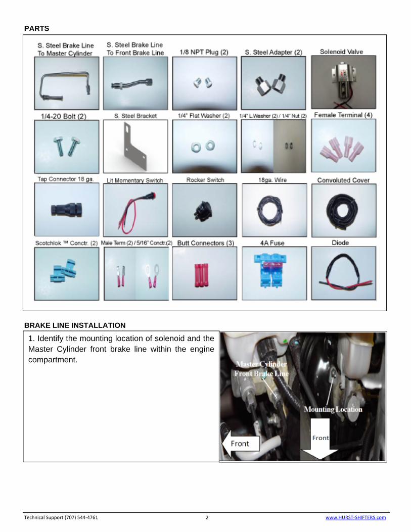
1. Identify the mounting location of solenoid and the Master Cylinder front brake line within the engine compartment.
Technical Support (707) 544‐4761 3 www.HURST‐SHIFTERS.com
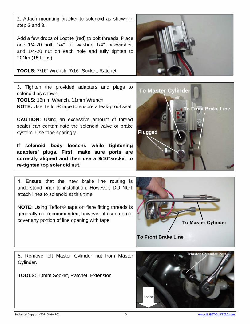
2. Attach mounting bracket to solenoid as shown in step 2 and 3. Add a few drops of Loctite (red) to bolt threads. Place one 1/4-20 bolt, 1/4” flat washer, 1/4” lockwasher, and 1/4-20 nut on each hole and fully tighten to 20Nm (15 ft-lbs). TOOLS: 7/16” Wrench, 7/16” Socket, Ratchet
3. Tighten the provided adapters and plugs to solenoid as shown. TOOLS: 16mm Wrench, 11mm Wrench NOTE: Use Teflon® tape to ensure a leak-proof seal. CAUTION: Using an excessive amount of thread sealer can contaminate the solenoid valve or brake system. Use tape sparingly. If solenoid body loosens while tightening adapters/ plugs. First, make sure ports are correctly aligned and then use a 9/16”socket to re-tighten top solenoid nut.
To Master Cylinder
To Front Brake Line
Plugged
To Master Cylinder
To Front Brake Line
4. Ensure that the new brake line routing is understood prior to installation. However, DO NOT attach lines to solenoid at this time. NOTE: Using Teflon® tape on flare fitting threads is generally not recommended, however, if used do not cover any portion of line opening with tape.
5. Remove left Master Cylinder nut from Master Cylinder. TOOLS: 13mm Socket, Ratchet, Extension
Technical Support (707) 544‐4761 4 www.HURST‐SHIFTERS.com
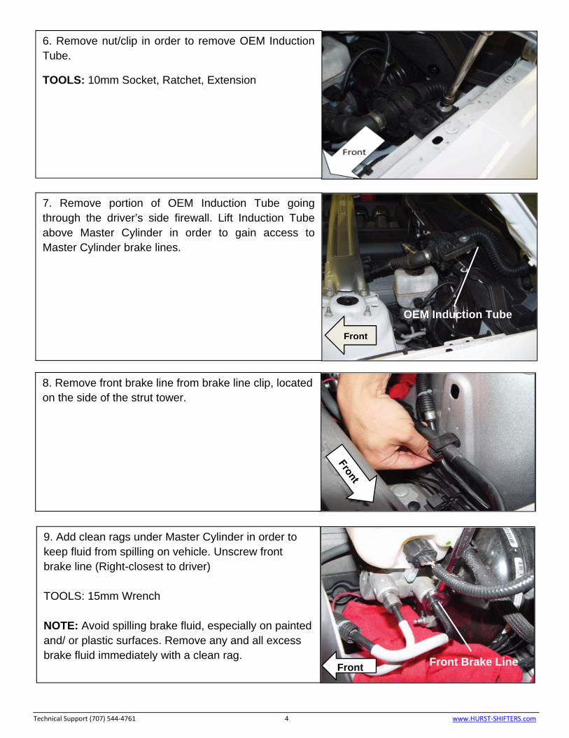
6. Remove nut/clip in order to remove OEM Induction Tube.
TOOLS: 10mm Socket, Ratchet, Extension
7. Remove portion of OEM Induction Tube going through the driver’s side firewall. Lift Induction Tube above Master Cylinder in order to gain access to Master Cylinder brake lines.
OEM Induction Tube
Front
8. Remove front brake line from brake line clip, located on the side of the strut tower.
9. Add clean rags under Master Cylinder in order to keep fluid from spilling on vehicle. Unscrew front brake line (Right-closest to driver) TOOLS: 15mm Wrench NOTE: Avoid spilling brake fluid, especially on painted and/ or plastic surfaces. Remove any and all excess brake fluid immediately with a clean rag.
Front Brake LineFront
Technical Support (707) 544‐4761 5 www.HURST‐SHIFTERS.com
10. Recommended Installation Method: Thread the Hurst Roll Control brake line into the OEM front brake line, however, do not completely tighten fitting at this time to allow for minor adjustments. Thread the Hurst Roll Control brake line into the adapter, finger tight. Push OEM brake line down to allow mounting bracket hole installation onto the Master Cylinder stud. (Slight adjustment (bending/flexing) of lines may be required for proper alignment). Once line is aligned, tighten all flare fittings. DO NOT OVER TIGHTEN AS THIS WILL CAUSE LEAKS. TOOLS: 15mm Wrench (Brake Line nut) 16mm Wrench (Adapter)
Front
Front
11. Recommended Installation Method: Thread the Hurst Roll Control brake line into the Master Cylinder, however, do not completely tighten fitting at this time to allow for minor adjustments. Thread Hurst Roll Control brake line into the adapter, finger tight. (Slight adjustment (bending/flexing) of lines may be required for proper alignment). Once line is aligned, tighten all flare fittings. DO NOT OVER TIGHTEN AS THIS WILL CAUSE LEAKS. TOOLS: 15mm Wrench (Brake Line nut) 16mm Wrench (Adapter)
12. Thread nut back onto master Cylinder stud, tighten Master Cylinder nut to 25Nm (18ft.-lbs). TOOLS: 13mm Socket, Ratchet, Extension
Front
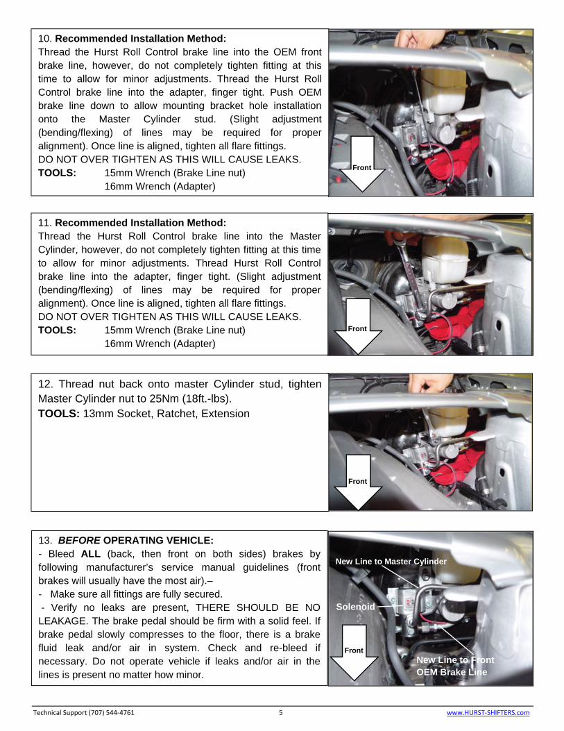
New Line to Master Cylinder
Solenoid
New Line to Front OEM Brake Line
Front
13. BEFORE OPERATING VEHICLE: - Bleed ALL (back, then front on both sides) brakes by following manufacturer’s service manual guidelines (front brakes will usually have the most air).– - Make sure all fittings are fully secured. - Verify no leaks are present, THERE SHOULD BE NO LEAKAGE. The brake pedal should be firm with a solid feel. If brake pedal slowly compresses to the floor, there is a brake fluid leak and/or air in system. Check and re-bleed if necessary. Do not operate vehicle if leaks and/or air in the lines is present no matter how minor.
WIRING INSTALLATION
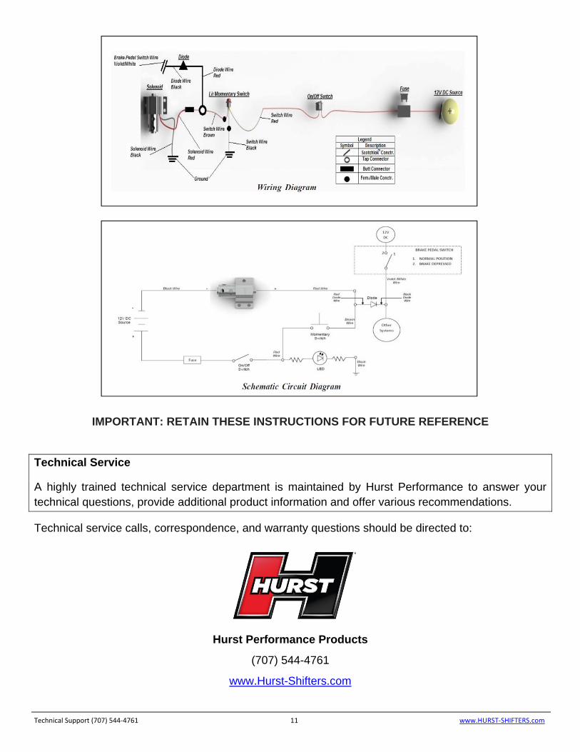
NOTE: The Hurst Roll Control Solenoid Valve is designed for 12V DC operation only. For added safety, two switches (arming and activation) are provided in this kit. Following the wiring recommendation properly will prevent accidental engagement of the Hurst Roll Control system. Disconnect negative (-) battery terminal. If more wire is needed then what is provided, use #18 gauge standard insulated automotive wire to assure good electrical connection and conductivity. Wiring should be as neat and direct as possible. DO NOT connect wiring in such a fashion as to apply added stress or excessive stretch to wires. Use convoluted sleeve to protect wires, keep wiring away from sharp edges/corners, hot engine, and exhaust components. Join all splices by using the provided connectors/terminals and wrap each splice/connection with an adequate grade of electrical tape. A fuse holder with a 4-amp fuse is provided (See wiring diagrams for wiring details on page 11) and should be incorporated into the wiring circuit. The fuse can protect the electrical system in the event of a short circuit. A Diode is also included to provide added protection against reverse voltage.
Technical Support (707) 544‐4761 6 www.HURST‐SHIFTERS.com
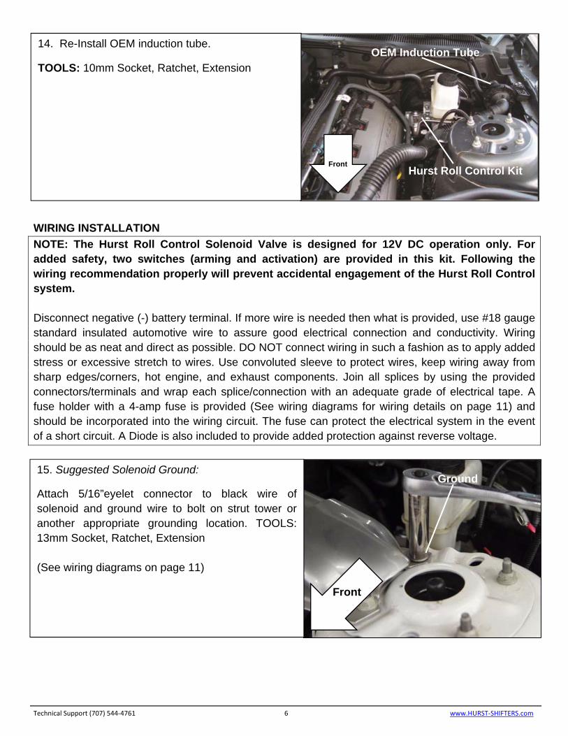
14. Re-Install OEM induction tube.
TOOLS: 10mm Socket, Ratchet, Extension OEM Induction Tube
Hurst Roll Control KitFront
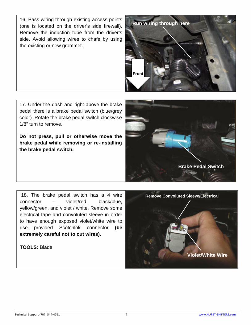
15. Suggested Solenoid Ground:
Attach 5/16”eyelet connector to black wire of solenoid and ground wire to bolt on strut tower or another appropriate grounding location. TOOLS: 13mm Socket, Ratchet, Extension (See wiring diagrams on page 11)
Front
Ground
Technical Support (707) 544‐4761 7 www.HURST‐SHIFTERS.com
16. Pass wiring through existing access points (one is located on the driver’s side firewall). Remove the induction tube from the driver’s side. Avoid allowing wires to chafe by using the existing or new grommet.
Run wiring through here
Front
17. Under the dash and right above the brake pedal there is a brake pedal switch (blue/grey color) .Rotate the brake pedal switch clockwise 1/8” turn to remove.
Do not press, pull or otherwise move the brake pedal while removing or re-installing the brake pedal switch.
Brake Pedal Switch
18. The brake pedal switch has a 4 wire connector – violet/red, black/blue, yellow/green, and violet / white. Remove some electrical tape and convoluted sleeve in order to have enough exposed violet/white wire to use provided Scotchlok connector (be extremely careful not to cut wires). TOOLS: Blade
Remove Convoluted Sleeve/Electrical
Violet/White Wire
Technical Support (707) 544‐4761 8 www.HURST‐SHIFTERS.com
19. Tap the black wire of provided diode into the violet/white wire of the brake pedal switch using provided Scotchlok connector. Tap the red wire of the provided diode into the brown wire of the momentary switch using provided 18ga connector. Connecting the diode is a critical step in making the Hurst Roll Control work properly. (See wiring diagrams on page 11) If the diode is not connected correctly or not installed there is a possible chance that AdvanceTrac might turn on while performing a burnout even if AdvanceTrac was turned fully OFF manually (At a complete stop, Depress and hold brake - press TC button for 5+ sec until “AdvanceTrac OFF” dash light appears). AdvanceTrac would stop the burnout and a “Service Advancetrac” dash light might turn on. If this occurs, turn off car to reset system and/or take it to you nearest Ford dealership to clear the ABS hard code. Re-install brake pedal switch.
Scotchlok™ Connector
Violet/White Wire
Tap Diode Red Wire into Brown Wire Switch Using 18ga. Tap Connector
Diode Black Wire
20. Suggested 12V Source: Tap into a 12V accessory/cigarette lighter socket wiring harness connection with provided Scotchlok™ connector or another appropriate 12V source. (See wiring diagrams on page 11)
Scotchlok™ Connector
12V Source
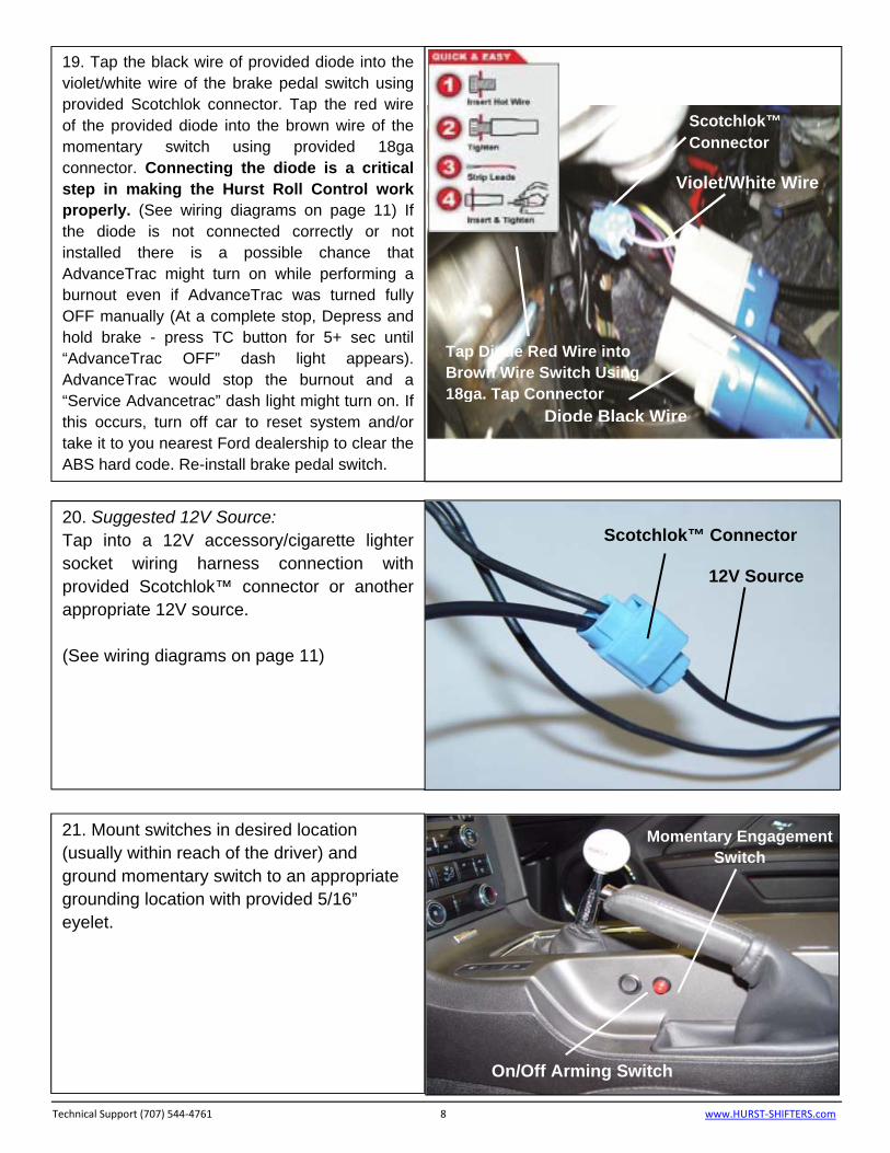
21. Mount switches in desired location (usually within reach of the driver) and ground momentary switch to an appropriate grounding location with provided 5/16” eyelet.
Momentary Engagement Switch
On/Off Arming Switch
Basic Switch Operation
System Arming: Turn on rocker switch, the momentary switch will light to indicate the Hurst Roll/Control system is ready or “hot”. Solenoid Engagement: Depress and hold momentary switch (Do not hold for more than 60 seconds).
See “Hurst Roll Control Operation” for competition use.
Caution: Holding the solenoid valve closed for more than 60 seconds can cause the fuse to burn-out, permanently damaging the solenoid valve, and/or result in other damage. De-activate (switch off) arming switch when the Hurst Roll Control is not in use to prevent accidental engagement.
Technical Support (707) 544‐4761 9 www.HURST‐SHIFTERS.com
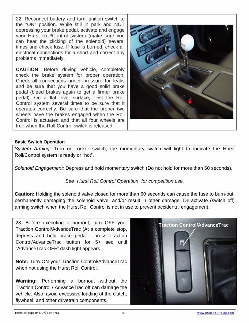
22. Reconnect battery and turn ignition switch to the “ON” position. While still in park and NOT depressing your brake pedal, activate and engage your Hurst Roll/Control system (make sure you can hear the clicking of the solenoid) several times and check fuse. If fuse is burned, check all electrical connections for a short and correct any problems immediately. CAUTION: Before driving vehicle, completely check the brake system for proper operation. Check all connections under pressure for leaks and be sure that you have a good solid brake pedal (bleed brakes again to get a firmer brake pedal). On a flat level surface, Test the Roll Control system several times to be sure that it operates correctly. Be sure that the proper two wheels have the brakes engaged when the Roll Control is actuated and that all four wheels are free when the Roll Control switch is released.
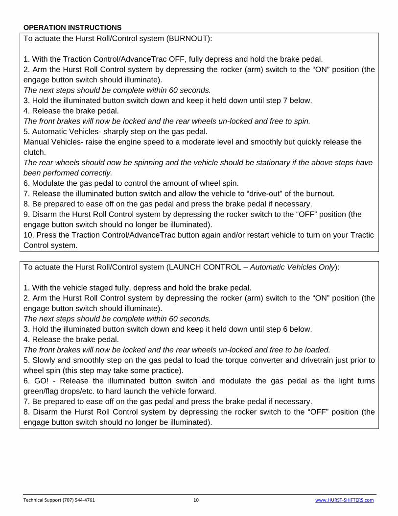
23. Before executing a burnout, turn OFF your Traction Control/AdvanceTrac (At a complete stop, depress and hold brake pedal - press Traction Control/AdvanceTrac button for 5+ sec until “AdvanceTrac OFF” dash light appears. Note: Turn ON your Traction Control/AdvanceTrac when not using the Hurst Roll Control. Warning: Performing a burnout without the Traction Control / AdvanceTrac off can damage the vehicle. Also, avoid excessive loading of the clutch, flywheel, and other drivetrain components.
Traction Control/AdvanceTrac
OPERATION INSTRUCTIONS
To actuate the Hurst Roll/Control system (BURNOUT): 1. With the Traction Control/AdvanceTrac OFF, fully depress and hold the brake pedal. 2. Arm the Hurst Roll Control system by depressing the rocker (arm) switch to the “ON” position (the engage button switch should illuminate). The next steps should be complete within 60 seconds. 3. Hold the illuminated button switch down and keep it held down until step 7 below. 4. Release the brake pedal. The front brakes will now be locked and the rear wheels un-locked and free to spin. 5. Automatic Vehicles- sharply step on the gas pedal. Manual Vehicles- raise the engine speed to a moderate level and smoothly but quickly release the clutch. The rear wheels should now be spinning and the vehicle should be stationary if the above steps have been performed correctly. 6. Modulate the gas pedal to control the amount of wheel spin. 7. Release the illuminated button switch and allow the vehicle to “drive-out” of the burnout. 8. Be prepared to ease off on the gas pedal and press the brake pedal if necessary. 9. Disarm the Hurst Roll Control system by depressing the rocker switch to the “OFF” position (the engage button switch should no longer be illuminated). 10. Press the Traction Control/AdvanceTrac button again and/or restart vehicle to turn on your Tractic Control system.
To actuate the Hurst Roll/Control system (LAUNCH CONTROL – Automatic Vehicles Only): 1. With the vehicle staged fully, depress and hold the brake pedal. 2. Arm the Hurst Roll Control system by depressing the rocker (arm) switch to the “ON” position (the engage button switch should illuminate). The next steps should be complete within 60 seconds. 3. Hold the illuminated button switch down and keep it held down until step 6 below. 4. Release the brake pedal. The front brakes will now be locked and the rear wheels un-locked and free to be loaded. 5. Slowly and smoothly step on the gas pedal to load the torque converter and drivetrain just prior to wheel spin (this step may take some practice). 6. GO! - Release the illuminated button switch and modulate the gas pedal as the light turns green/flag drops/etc. to hard launch the vehicle forward. 7. Be prepared to ease off on the gas pedal and press the brake pedal if necessary. 8. Disarm the Hurst Roll Control system by depressing the rocker switch to the “OFF” position (the engage button switch should no longer be illuminated).
Technical Support (707) 544‐4761 10 www.HURST‐SHIFTERS.com
IMPORTANT: RETAIN THESE INSTRUCTIONS FOR FUTURE REFERENCE
Technical Service
A highly trained technical service department is maintained by Hurst Performance to answer your technical questions, provide additional product information and offer various recommendations.
Technical service calls, correspondence, and warranty questions should be directed to:
Hurst Performance Products
(707) 544-4761
www.Hurst-Shifters.com Technical Support (707) 544‐4761 11 www.HURST‐SHIFTERS.com