ball screw - support unit
DESCRIPTION
TRANSCRIPT
A15-314
Support Unit Models EK, BK, FK, EF, BF and FF
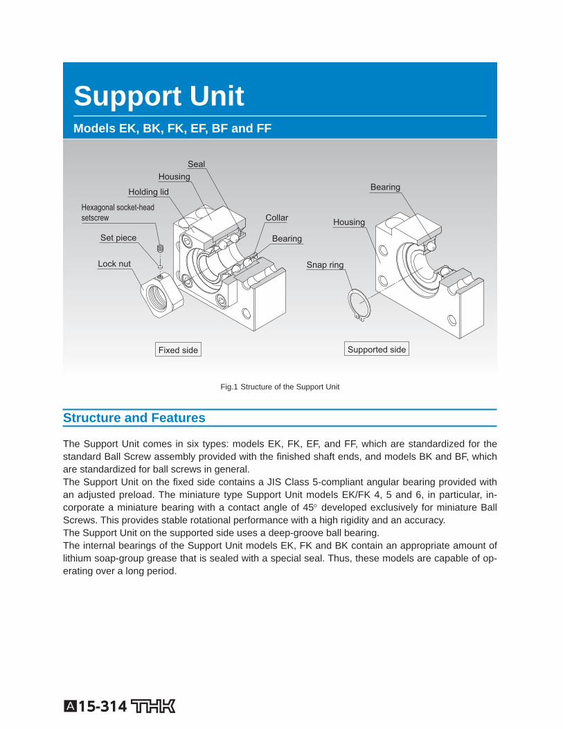
Fixed side Supported side
Bearing
Bearing
Housing
Housing
Lock nut
Set piece
Hexagonal socket-head setscrew
Snap ring
Holding lid
Seal
Collar
Fig.1 Structure of the Support Unit
Structure and Features
The Support Unit comes in six types: models EK, FK, EF, and FF, which are standardized for the standard Ball Screw assembly provided with the nished shaft ends, and models BK and BF, which are standardized for ball screws in general. The Support Unit on the xed side contains a JIS Class 5-compliant angular bearing provided with an adjusted preload. The miniature type Support Unit models EK/FK 4, 5 and 6, in particular, in-corporate a miniature bearing with a contact angle of 45 developed exclusively for miniature Ball Screws. This provides stable rotational performance with a high rigidity and an accuracy. The Support Unit on the supported side uses a deep-groove ball bearing. The internal bearings of the Support Unit models EK, FK and BK contain an appropriate amount of lithium soap-group grease that is sealed with a special seal. Thus, these models are capable of op-erating over a long period.
A15-315
Ball Screw
PeripheralsSupport Unit
[Uses the Optimal Bearing] To ensure the rigidity balance with the Ball Screw, the Support Unit uses an angular bearing (contact angle: 30 ; DF con guration) with a high rigidity and a low torque. Miniature Support Unit models EK/FK 4, 5 and 6 are incorporated with a miniature angular bearing with a contact angle of 45 de-veloped exclusively for miniature Ball Screws. This bearing has a greater contact angle of 45 and an increased number of balls with a smaller diameter. The high rigidity and accuracy of the miniature angular bearing provides the stable rotational performance.
[Support Unit Shapes] The square and round shapes are available for the Support Unit to allow the selection according to the intended use.
[Compact and Easy Installation] The Support Unit is compactly designed to accommodate the space in the installation site. As the bearing is provided with an appropriately adjusted preload, the Support Unit can be assembled with a Ball Screw unit with no further machining. Accordingly, the required man-hours in the assembly can be reduced and the assembly accuracy can be increased.
A15-316
Type
[For the Fixed Side]
Square Type Model EK Speci cation Table⇒A15-324
(Inner diameter: 4 to 20)
Round Type Model FK Speci cation Table⇒A15-328
(Inner diameter: 4 to 30)
Square Type Model BK Speci cation Table⇒A15-326
(Inner diameter: 10 to 40)
[For the Supported Side]
Square Type Model EF Speci cation Table⇒A15-332
(Inner diameter: 6 to 20)
Round Type Model FF Speci cation Table⇒A15-336
(Inner diameter: 6 to 30)
Square Type Model BF Speci cation Table⇒A15-334
(Inner diameter: 8 to 40)
A15-317
Ball Screw
PeripheralsSupport Unit
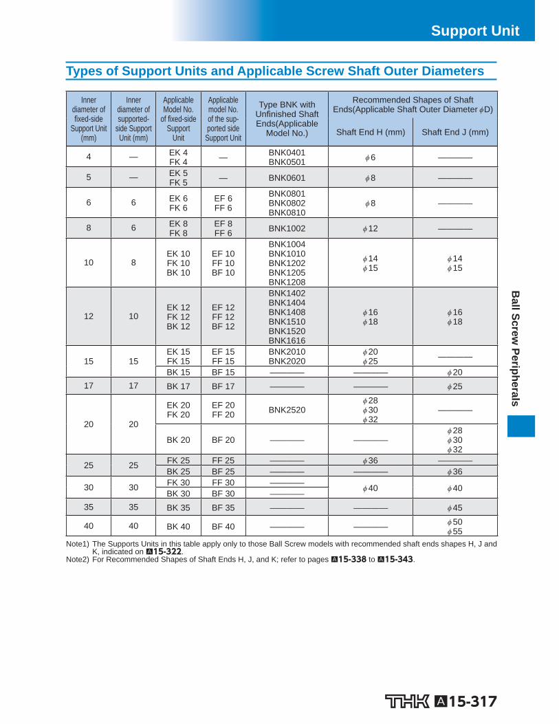
Types of Support Units and Applicable Screw Shaft Outer Diameters
Inner diameter of
xed-side Support Unit
(mm)
Inner diameter of supported-
side Support Unit (mm)
Applicable Model No.
of xed-side Support
Unit
Applicable model No. of the sup-ported side
Support Unit
Type BNK with Un nished Shaft Ends(Applicable
Model No.)
Recommended Shapes of Shaft Ends(Applicable Shaft Outer Diameter D)
Shaft End H (mm) Shaft End J (mm)
4 — EK 4 FK 4 — BNK0401
BNK0501 6 ————
5 — EK 5 FK 5 — BNK0601 8 ————
6 6 EK 6 FK 6
EF 6 FF 6
BNK0801 BNK0802 BNK0810
8 ————
8 6 EK 8 FK 8
EF 8 FF 6 BNK1002 12 ————
10 8 EK 10 FK 10 BK 10
EF 10 FF 10 BF 10
BNK1004 BNK1010 BNK1202 BNK1205 BNK1208
14 15
14 15
12 10 EK 12 FK 12 BK 12
EF 12 FF 12 BF 12
BNK1402 BNK1404 BNK1408 BNK1510 BNK1520 BNK1616
16 18
16 18
15 15 EK 15 FK 15
EF 15 FF 15
BNK2010 BNK2020
20 25 ————
BK 15 BF 15 ———— ———— 20 17 17 BK 17 BF 17 ———— ———— 25
20 20
EK 20 FK 20
EF 20 FF 20 BNK2520
28 30 32
————
BK 20 BF 20 ———— ———— 28 30 32
25 25 FK 25 FF 25 ———— 36 ———— BK 25 BF 25 ———— ———— 36
30 30 FK 30 FF 30 ———— 40 40 BK 30 BF 30 ———— 35 35 BK 35 BF 35 ———— ———— 45
40 40 BK 40 BF 40 ———— ———— 50 55
Note1) The Supports Units in this table apply only to those Ball Screw models with recommended shaft ends shapes H, J and K, indicated on A15-322 .
Note2) For Recommended Shapes of Shaft Ends H, J, and K; refer to pages A15-338 to A15-343 .
A15-318
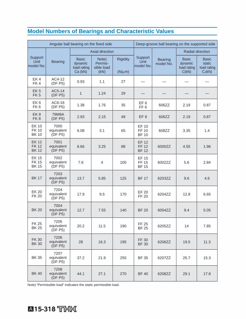
Model Numbers of Bearings and Characteristic Values
Angular ball bearing on the xed side Deep-groove ball bearing on the supported side
SupportUnit
model No. Bearing
Axial direction Support
Unit model No.
Bearing model No.
Radial direction
Basic dynamic
load rating Ca (kN)
Note) Permis-
sible load (kN)
Rigidity
(N/ m)
Basic dynamic
load rating C(kN)
Basic static
load rating C 0 (kN)
EK 4 FK 4
AC4-12 (DF P5) 0.93 1.1 27 — — — —
EK 5 FK 5
AC5-14 (DF P5) 1 1.24 29 — — — —
EK 6 FK 6
AC6-16 (DF P5) 1.38 1.76 35 EF 6
FF 6 606ZZ 2.19 0.87
EK 8 FK 8
79M8A (DF P5) 2.93 2.15 49 EF 8 606ZZ 2.19 0.87
EK 10 FK 10 BK 10
7000 equivalent (DF P5)
6.08 3.1 65 EF 10 FF 10 BF 10
608ZZ 3.35 1.4
EK 12 FK 12 BK 12
7001 equivalent (DF P5)
6.66 3.25 88 EF 12 FF 12 BF 12
6000ZZ 4.55 1.96
EK 15 FK 15 BK 15
7002 equivalent (DF P5)
7.6 4 100 EF 15 FF 15 BF 15
6002ZZ 5.6 2.84
BK 17 7203
equivalent (DF P5)
13.7 5.85 125 BF 17 6203ZZ 9.6 4.6
EK 20 FK 20
7204 equivalent (DF P5)
17.9 9.5 170 EF 20 FF 20 6204ZZ 12.8 6.65
BK 20 7004
equivalent (DF P5)
12.7 7.55 140 BF 20 6004ZZ 9.4 5.05
FK 25 BK 25
7205 equivalent (DF P5)
20.2 11.5 190 FF 25 BF 25 6205ZZ 14 7.85
FK 30 BK 30
7206 equivalent (DF P5)
28 16.3 195 FF 30 BF 30 6206ZZ 19.5 11.3
BK 35 7207
equivalent (DF P5)
37.2 21.9 255 BF 35 6207ZZ 25.7 15.3
BK 40 7208
equivalent (DF P5)
44.1 27.1 270 BF 40 6208ZZ 29.1 17.8
Note) “Permissible load” indicates the static permissible load.
A15-319
Ball Screw
PeripheralsSupport Unit
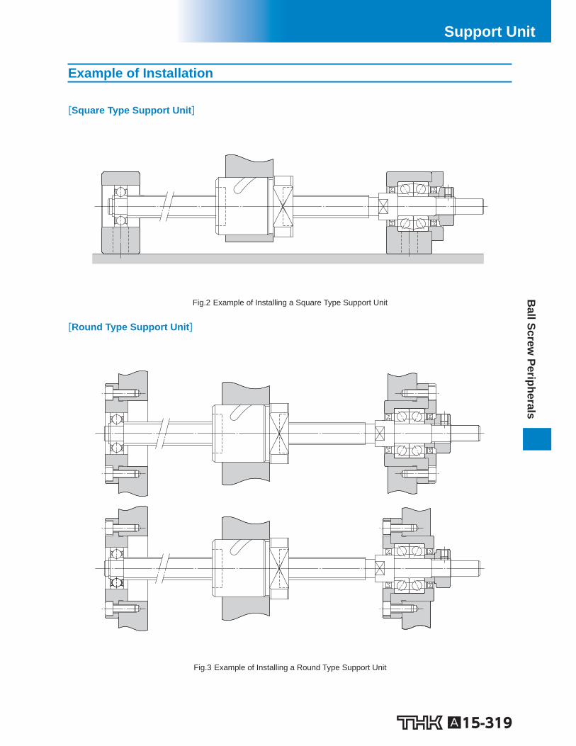
Example of Installation
[Square Type Support Unit]
Fig.2 Example of Installing a Square Type Support Unit
[Round Type Support Unit]
Fig.3 Example of Installing a Round Type Support Unit
A15-320
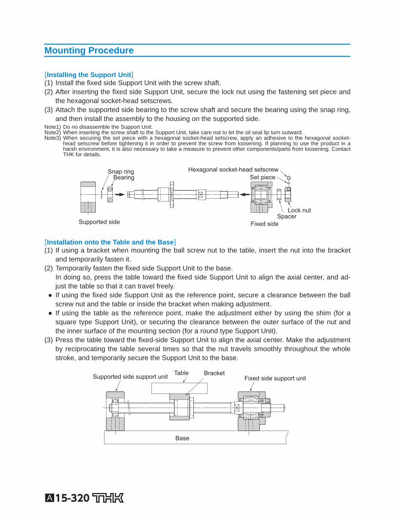
Mounting Procedure
[Installing the Support Unit] (1) Install the xed side Support Unit with the screw shaft. (2) After inserting the xed side Support Unit, secure the lock nut using the fastening set piece and
the hexagonal socket-head setscrews. (3) Attach the supported side bearing to the screw shaft and secure the bearing using the snap ring,
and then install the assembly to the housing on the supported side. Note1) Do no disassemble the Support Unit. Note2) When inserting the screw shaft to the Support Unit, take care not to let the oil seal lip turn outward. Note3) When securing the set piece with a hexagonal socket-head setscrew, apply an adhesive to the hexagonal socket-
head setscrew before tightening it in order to prevent the screw from loosening. If planning to use the product in a harsh environment, it is also necessary to take a measure to prevent other components/parts from loosening. Contact THK for details.
Supported side
Bearing Snap ring
Fixed side Spacer
Set piece Hexagonal socket-head setscrew
Lock nut
[Installation onto the Table and the Base] (1) If using a bracket when mounting the ball screw nut to the table, insert the nut into the bracket
and temporarily fasten it. (2) Temporarily fasten the xed side Support Unit to the base.
In doing so, press the table toward the xed side Support Unit to align the axial center, and ad-just the table so that it can travel freely.
If using the xed side Support Unit as the reference point, secure a clearance between the ball screw nut and the table or inside the bracket when making adjustment.
If using the table as the reference point, make the adjustment either by using the shim (for a square type Support Unit), or securing the clearance between the outer surface of the nut and the inner surface of the mounting section (for a round type Support Unit).
(3) Press the table toward the xed-side Support Unit to align the axial center. Make the adjustment by reciprocating the table several times so that the nut travels smoothly throughout the whole stroke, and temporarily secure the Support Unit to the base.
Base
Fixed side support unitBracket Table Supported side support unit
A15-321
Ball Screw
PeripheralsSupport Unit
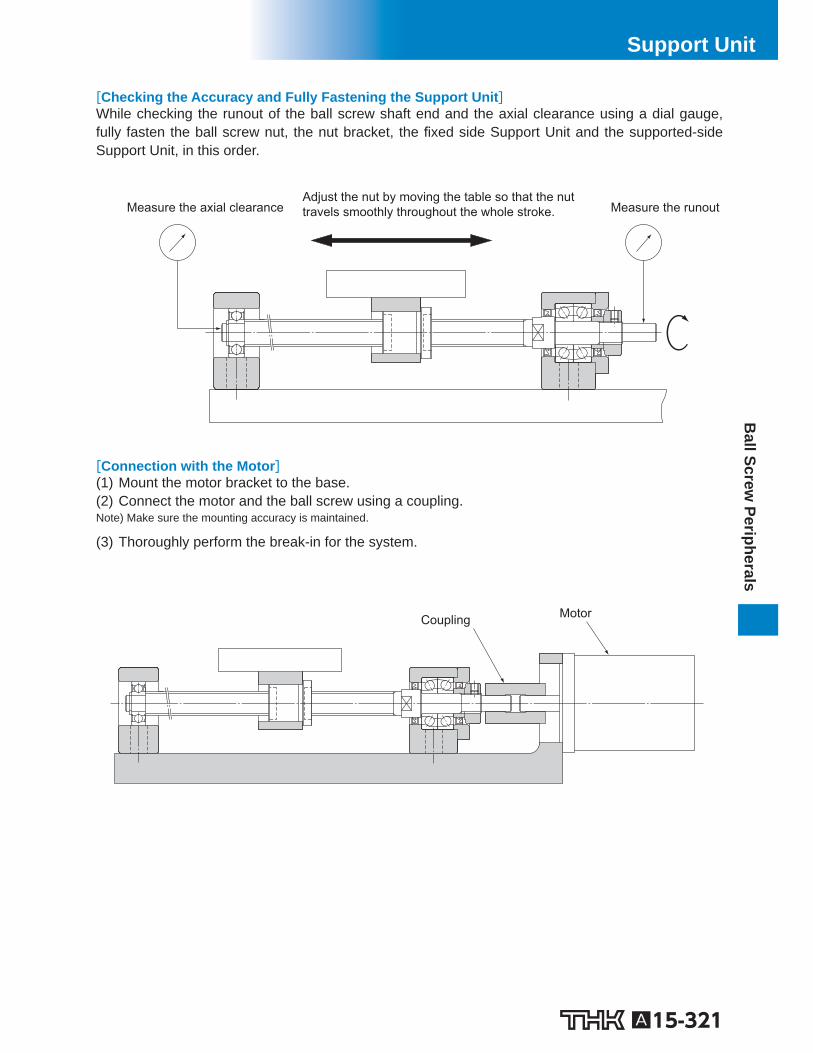
[Checking the Accuracy and Fully Fastening the Support Unit] While checking the runout of the ball screw shaft end and the axial clearance using a dial gauge, fully fasten the ball screw nut, the nut bracket, the xed side Support Unit and the supported-side Support Unit, in this order.
Adjust the nut by moving the table so that the nut travels smoothly throughout the whole stroke. Measure the runoutMeasure the axial clearance
[Connection with the Motor] (1) Mount the motor bracket to the base. (2) Connect the motor and the ball screw using a coupling. Note) Make sure the mounting accuracy is maintained.
(3) Thoroughly perform the break-in for the system.
Motor Coupling
A15-322
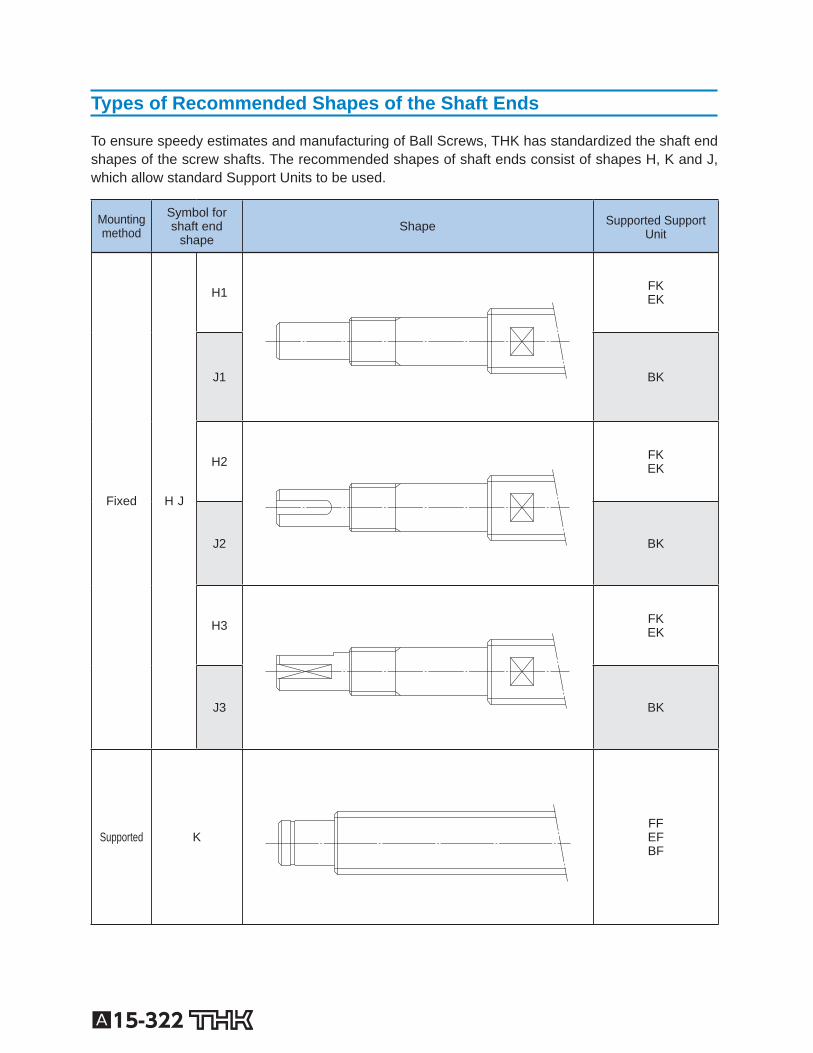
Types of Recommended Shapes of the Shaft Ends
To ensure speedy estimates and manufacturing of Ball Screws, THK has standardized the shaft end shapes of the screw shafts. The recommended shapes of shaft ends consist of shapes H, K and J, which allow standard Support Units to be used.
Mounting method
Symbol forshaft end
shape Shape Supported Support
Unit
Fixed H J
H1
FK EK
J1
BK
H2
FK EK
J2
BK
H3
FK EK
J3
BK
Supported K
FF EF BF
A15-323
Ball Screw
PeripheralsSupport Unit
A15-324 To download a desired data, search for the corresponding model number in the Technical site. https://tech.thk.com
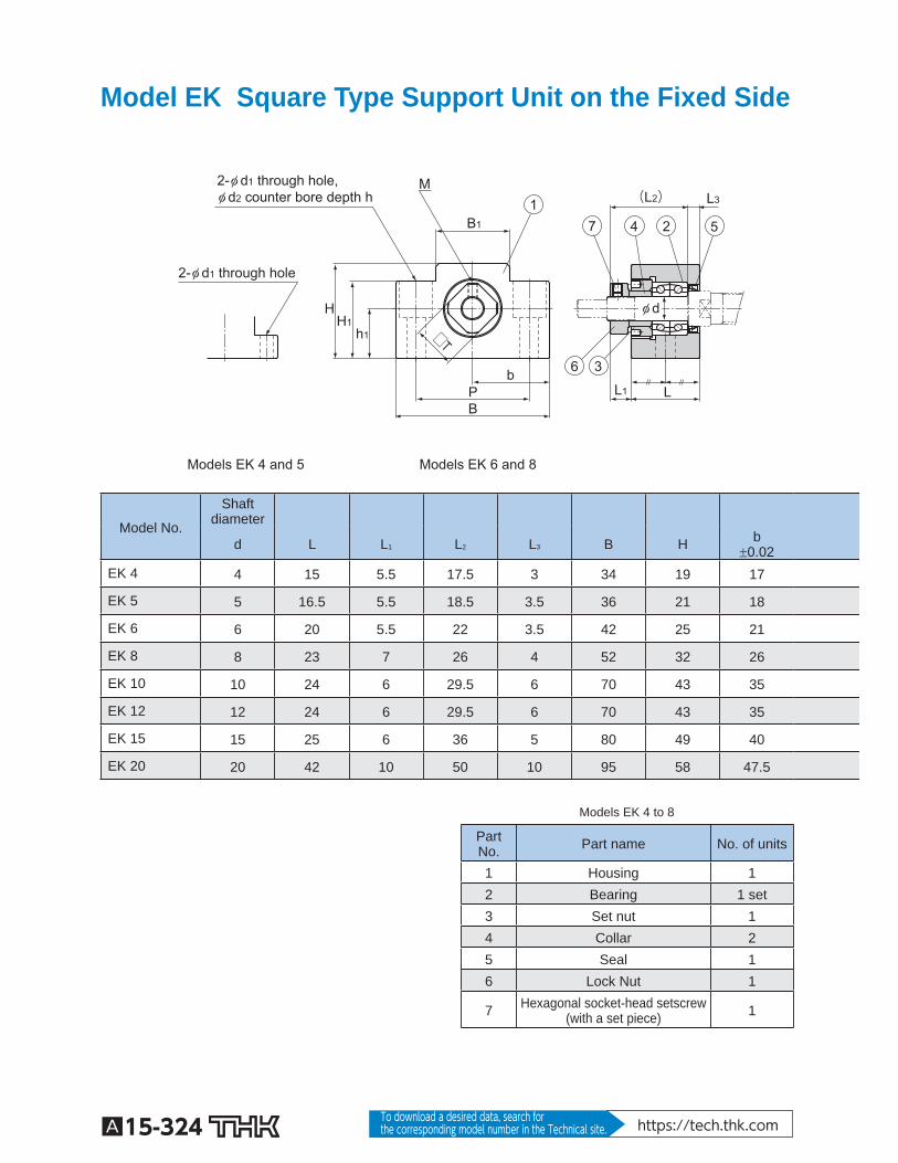
Model EK Square Type Support Unit on the Fixed Side
2-φ d1 through hole, φ d2 counter bore depth h
2-φ d1 through hole
Models EK 4 and 5 Models EK 6 and 8
b
H1 h1
H
M
P
B1
B
φ d
L
L3 (L2)
L1
3
5 2 4
□T
1 7
6
Model No.
Shaftdiameter
d L L 1 L 2 L 3 B H b 0.02
EK 4 4 15 5.5 17.5 3 34 19 17
EK 5 5 16.5 5.5 18.5 3.5 36 21 18
EK 6 6 20 5.5 22 3.5 42 25 21
EK 8 8 23 7 26 4 52 32 26
EK 10 10 24 6 29.5 6 70 43 35
EK 12 12 24 6 29.5 6 70 43 35
EK 15 15 25 6 36 5 80 49 40
EK 20 20 42 10 50 10 95 58 47.5
Models EK 4 to 8
Part No. Part name No. of units
1 Housing 1 2 Bearing 1 set 3 Set nut 1 4 Collar 2 5 Seal 1 6 Lock Nut 1
7 Hexagonal socket-head setscrew (with a set piece) 1
A15-325
Ball Screw
PeripheralsSupport Unit
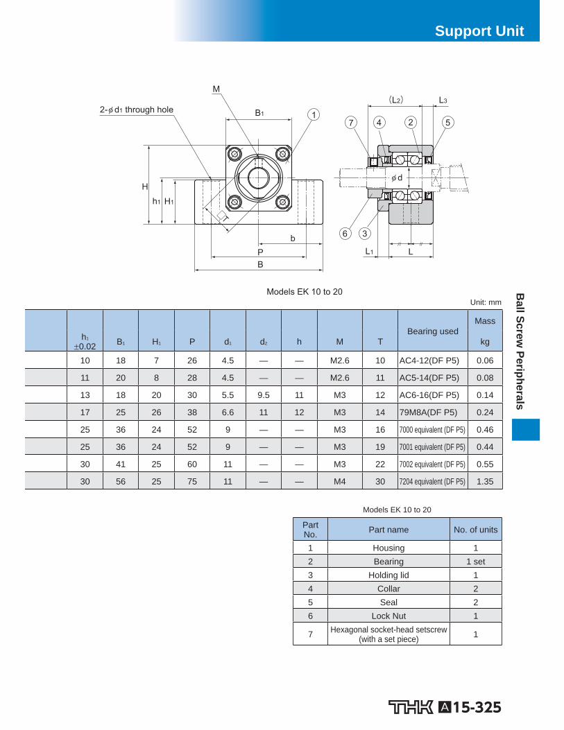
2-φ d1 through hole
Models EK 10 to 20
(L2) L3
φ d
L1 L
□T
b
H1 h1
H
M
P
B1
B
5 2 4
3 6
7 1
Unit: mm
Bearing used
Mass
h 1 0.02 B 1 H 1 P d 1 d 2 h M T kg
10 18 7 26 4.5 — — M2.6 10 AC4-12(DF P5) 0.06
11 20 8 28 4.5 — — M2.6 11 AC5-14(DF P5) 0.08
13 18 20 30 5.5 9.5 11 M3 12 AC6-16(DF P5) 0.14
17 25 26 38 6.6 11 12 M3 14 79M8A(DF P5) 0.24
25 36 24 52 9 — — M3 16 7000 equivalent (DF P5) 0.46
25 36 24 52 9 — — M3 19 7001 equivalent (DF P5) 0.44
30 41 25 60 11 — — M3 22 7002 equivalent (DF P5) 0.55
30 56 25 75 11 — — M4 30 7204 equivalent (DF P5) 1.35
Models EK 10 to 20
Part No. Part name No. of units
1 Housing 1 2 Bearing 1 set 3 Holding lid 1 4 Collar 2 5 Seal 2 6 Lock Nut 1
7 Hexagonal socket-head setscrew (with a set piece) 1
A15-326 To download a desired data, search for the corresponding model number in the Technical site. https://tech.thk.com
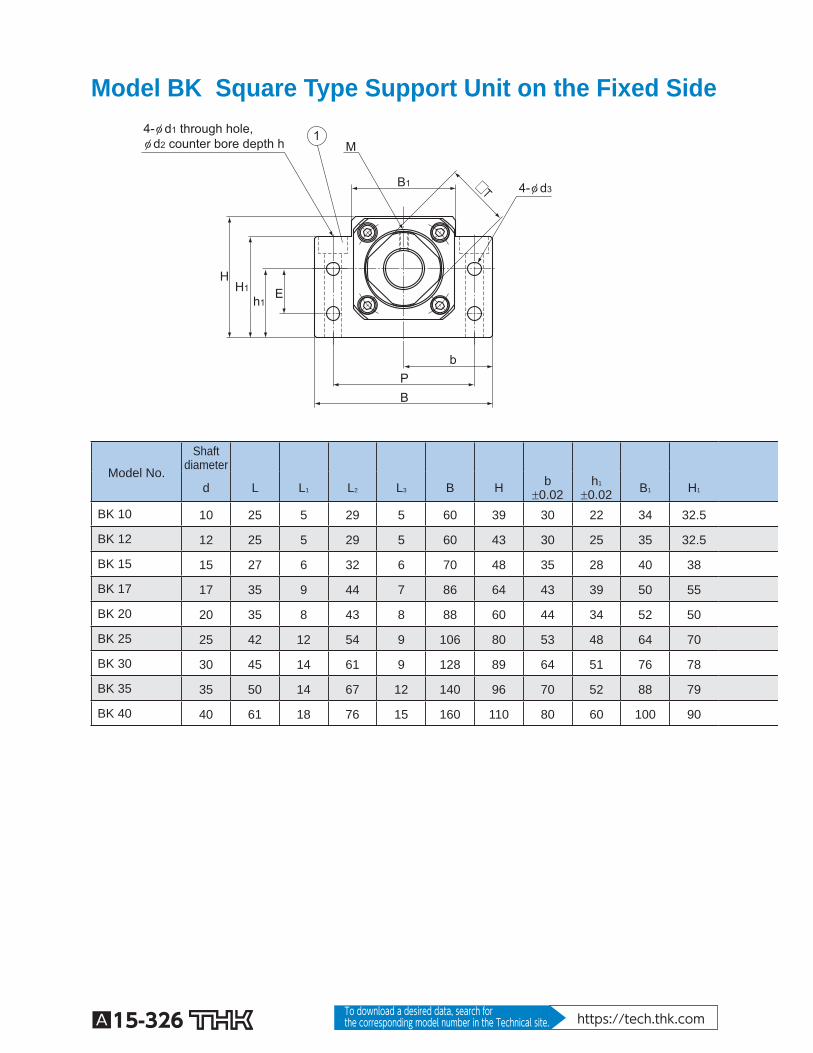
Model BK Square Type Support Unit on the Fixed Side
4-φ d1 through hole,φ d2 counter bore depth h
□T
b
4-φ d3
H1 E h1
H
M
P
B1
B
1
Model No.
Shaftdiameter
d L L 1 L 2 L 3 B H b 0.02
h 1 0.02 B 1 H 1
BK 10 10 25 5 29 5 60 39 30 22 34 32.5
BK 12 12 25 5 29 5 60 43 30 25 35 32.5
BK 15 15 27 6 32 6 70 48 35 28 40 38
BK 17 17 35 9 44 7 86 64 43 39 50 55
BK 20 20 35 8 43 8 88 60 44 34 52 50
BK 25 25 42 12 54 9 106 80 53 48 64 70
BK 30 30 45 14 61 9 128 89 64 51 76 78
BK 35 35 50 14 67 12 140 96 70 52 88 79
BK 40 40 61 18 76 15 160 110 80 60 100 90
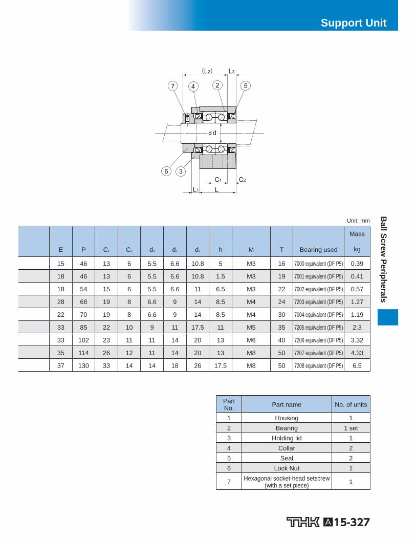
A15-327
Ball Screw
PeripheralsSupport Unit
L3 (L2)
C2
φ d
C1
L1 L
5 2 4
3 6
7
Unit: mm
Mass
E P C 1 C 2 d 3 d 1 d 2 h M T Bearing used kg
15 46 13 6 5.5 6.6 10.8 5 M3 16 7000 equivalent (DF P5) 0.39
18 46 13 6 5.5 6.6 10.8 1.5 M3 19 7001 equivalent (DF P5) 0.41
18 54 15 6 5.5 6.6 11 6.5 M3 22 7002 equivalent (DF P5) 0.57
28 68 19 8 6.6 9 14 8.5 M4 24 7203 equivalent (DF P5) 1.27
22 70 19 8 6.6 9 14 8.5 M4 30 7004 equivalent (DF P5) 1.19
33 85 22 10 9 11 17.5 11 M5 35 7205 equivalent (DF P5) 2.3
33 102 23 11 11 14 20 13 M6 40 7206 equivalent (DF P5) 3.32
35 114 26 12 11 14 20 13 M8 50 7207 equivalent (DF P5) 4.33
37 130 33 14 14 18 26 17.5 M8 50 7208 equivalent (DF P5) 6.5
Part No. Part name No. of units
1 Housing 1 2 Bearing 1 set 3 Holding lid 1 4 Collar 2 5 Seal 2 6 Lock Nut 1
7 Hexagonal socket-head setscrew (with a set piece) 1

A15-328 To download a desired data, search for the corresponding model number in the Technical site. https://tech.thk.com
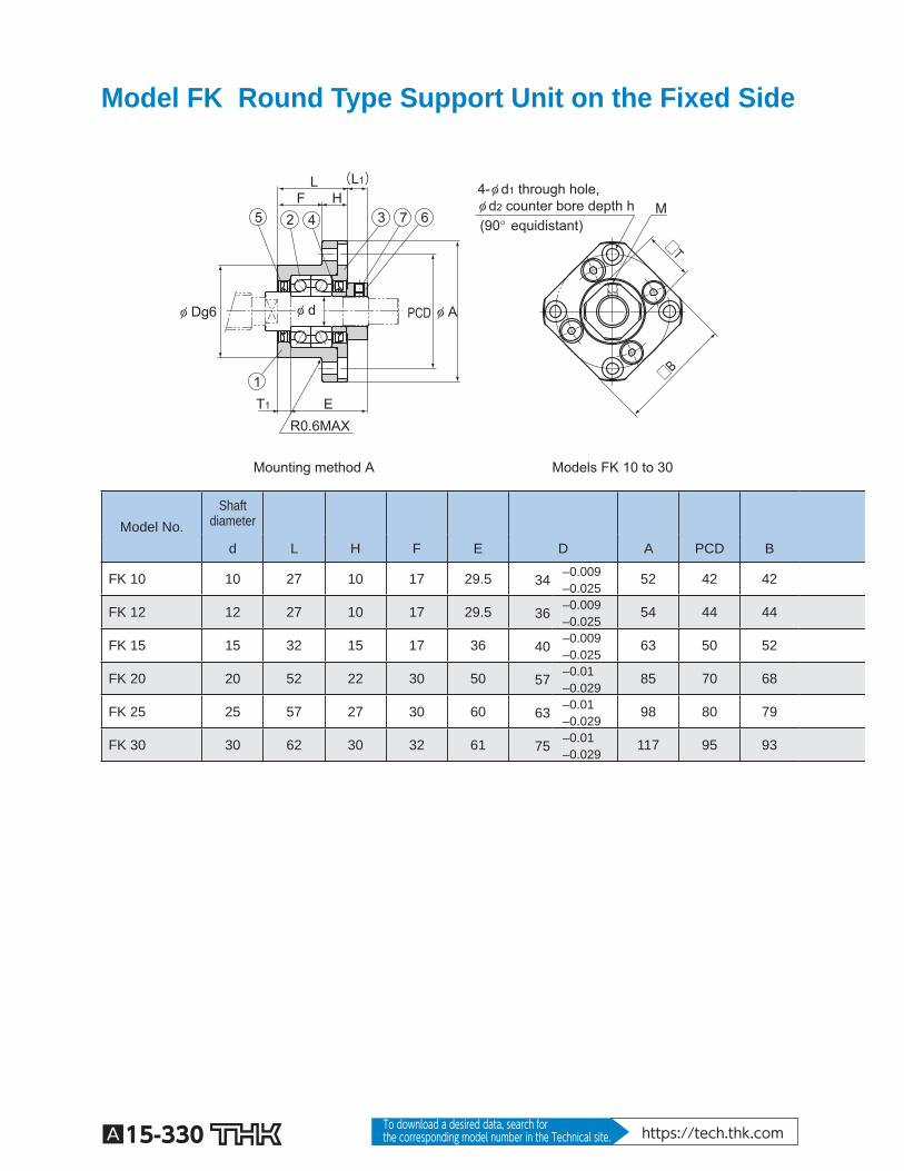
Model FK Round Type Support Unit on the Fixed Side
Mounting method A Models FK 4 to 8
(90° equidistant)
4-φ d1 through hole, φ d2 counter bore depth h
L F H
φ APCD
E R0.6MAX
φ dφ Dg6
T1
(L1)
M
□B
□T
1
5 2 4 6 3 7
Model No. Shaft
diameter
d L H F E D A PCD B
FK 4 4 15 6 9 17.5 18 –0.006 –0.017
32 24 25
FK 5 5 16.5 6 10.5 18.5 20 –0.007 –0.02
34 26 26
FK 6 6 20 7 13 22 22 –0.007 –0.02
36 28 28
FK 8 8 23 9 14 26 28 –0.007 –0.02
43 35 35
A15-329
Ball Screw
PeripheralsSupport Unit
Mounting method B
φ d
L F H
E T2
(L2)
Unit: mm
Installationprocedure A
Installationprocedure B
Bearing used Mass
L 1 T 1 L 2 T 2 d 1 d 2 h M T kg
5.5 3 6.5 4 3.4 6.5 4 M2.6 10 AC4-12(DF P5) 0.05
5.5 3.5 7 5 3.4 6.5 4 M2.6 11 AC5-14(DF P5) 0.06
5.5 3.5 8.5 6.5 3.4 6.5 4 M3 12 AC6-16(DF P5) 0.08
7 4 10 7 3.4 6.5 4 M3 14 79M8A(DF P5) 0.15
Part No. Part name No. of units
1 Housing 1 2 Bearing 1 set 3 Set nut 1 4 Collar 2 5 Seal 1 6 Lock Nut 1
7 Hexagonal socket-head setscrew (with a set piece) 1
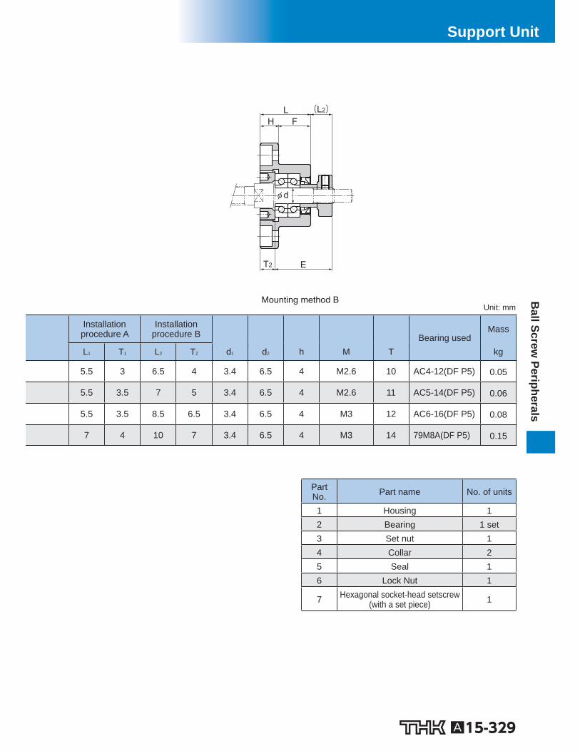
A15-330 To download a desired data, search for the corresponding model number in the Technical site. https://tech.thk.com
Model FK Round Type Support Unit on the Fixed Side
Mounting method A
(90° equidistant)
Models FK 10 to 30
4-φ d1 through hole, φ d2 counter bore depth h
L F H
(L1)
5 2 4 6 3 7
φ APCD φ dφ Dg6
E R0.6MAX
T1
1 □B
□T
M
Model No. Shaft
diameter
d L H F E D A PCD B
FK 10 10 27 10 17 29.5 34 –0.009 –0.025
52 42 42
FK 12 12 27 10 17 29.5 36 –0.009 –0.025
54 44 44
FK 15 15 32 15 17 36 40 –0.009 –0.025
63 50 52
FK 20 20 52 22 30 50 57 –0.01 –0.029
85 70 68
FK 25 25 57 27 30 60 63 –0.01 –0.029
98 80 79
FK 30 30 62 30 32 61 75 –0.01 –0.029
117 95 93
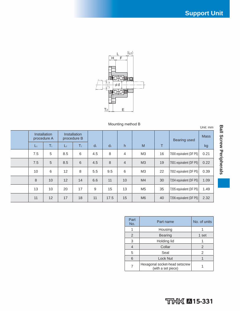
A15-331
Ball Screw
PeripheralsSupport Unit
Part No. Part name No. of units
1 Housing 1 2 Bearing 1 set 3 Holding lid 1 4 Collar 2 5 Seal 2 6 Lock Nut 1
7 Hexagonal socket-head setscrew (with a set piece) 1
Mounting method B
φ d
L F H
E T2
(L2)
Unit: mm
Installationprocedure A
Installationprocedure B
Bearing used Mass
L 1 T 1 L 2 T 2 d 1 d 2 h M T kg
7.5 5 8.5 6 4.5 8 4 M3 16 7000 equivalent (DF P5) 0.21
7.5 5 8.5 6 4.5 8 4 M3 19 7001 equivalent (DF P5) 0.22
10 6 12 8 5.5 9.5 6 M3 22 7002 equivalent (DF P5) 0.39
8 10 12 14 6.6 11 10 M4 30 7204 equivalent (DF P5) 1.09
13 10 20 17 9 15 13 M5 35 7205 equivalent (DF P5) 1.49
11 12 17 18 11 17.5 15 M6 40 7206 equivalent (DF P5) 2.32
A15-332 To download a desired data, search for the corresponding model number in the Technical site. https://tech.thk.com
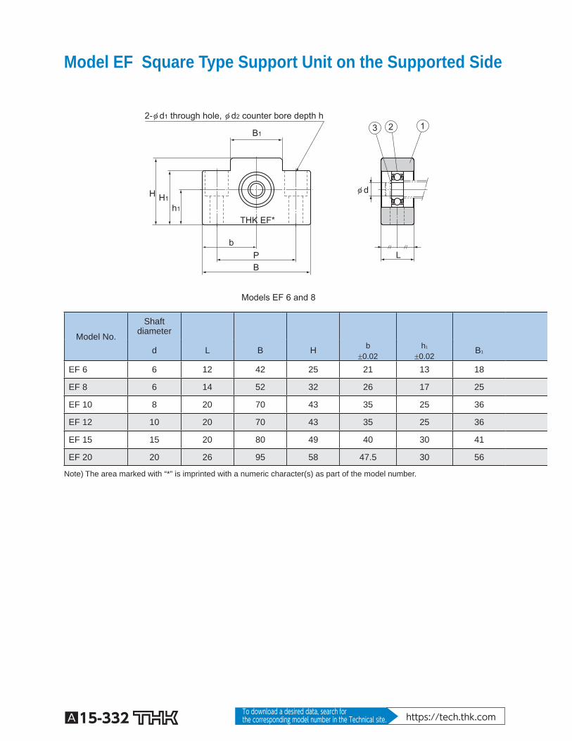
Model EF Square Type Support Unit on the Supported Side
2-φ d1 through hole, φ d2 counter bore depth h
Models EF 6 and 8
φ d
b P
B1
h1
H1 H
B L
2 3 1
THK EF*
Model No.
Shaftdiameter
d L B H b 0.02
h 1 0.02
B 1
EF 6 6 12 42 25 21 13 18
EF 8 6 14 52 32 26 17 25
EF 10 8 20 70 43 35 25 36
EF 12 10 20 70 43 35 25 36
EF 15 15 20 80 49 40 30 41
EF 20 20 26 95 58 47.5 30 56
Note) The area marked with “*” is imprinted with a numeric character(s) as part of the model number.
A15-333
Ball Screw
PeripheralsSupport Unit
Part No. Part name No. of units
1 Housing 1 2 Bearing 1 3 Snap ring 1
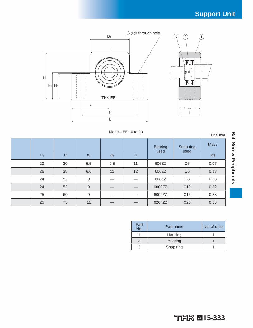
2-φ d1 through hole
Models EF 10 to 20
b P
H1 h1
H
B1
B L
2
φ d
3 1
THK EF*
Unit: mm
Bearingused
Snap ringused
Mass
H 1 P d 1 d 2 h kg
20 30 5.5 9.5 11 606ZZ C6 0.07
26 38 6.6 11 12 606ZZ C6 0.13
24 52 9 — — 608ZZ C8 0.33
24 52 9 — — 6000ZZ C10 0.32
25 60 9 — — 6002ZZ C15 0.38
25 75 11 — — 6204ZZ C20 0.63
A15-334 To download a desired data, search for the corresponding model number in the Technical site. https://tech.thk.com
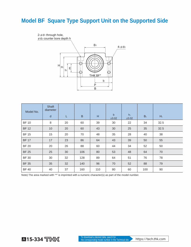
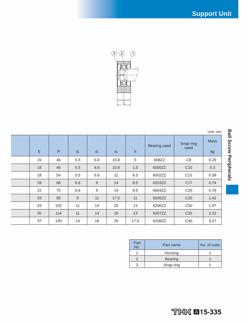
Model BF Square Type Support Unit on the Supported Side
2-φ d1 through hole,φ d2 counter bore depth h
b
4-φ d3
H1 E h1
H
P
B1
B
THK BF*
Model No.
Shaftdiameter
d L B H b 0.02
h 1 0.02
B 1 H 1
BF 10 8 20 60 39 30 22 34 32.5
BF 12 10 20 60 43 30 25 35 32.5
BF 15 15 20 70 48 35 28 40 38
BF 17 17 23 86 64 43 39 50 55
BF 20 20 26 88 60 44 34 52 50
BF 25 25 30 106 80 53 48 64 70
BF 30 30 32 128 89 64 51 76 78
BF 35 35 32 140 96 70 52 88 79
BF 40 40 37 160 110 80 60 100 90
Note) The area marked with “*” is imprinted with a numeric character(s) as part of the model number.
A15-335
Ball Screw
PeripheralsSupport Unit
Part No. Part name No. of units
1 Housing 1 2 Bearing 1 3 Snap ring 1
L
3
φ d
2 1
Unit: mm
Bearing used Snap ring
used
Mass
E P d 3 d 1 d 2 h kg
15 46 5.5 6.6 10.8 5 608ZZ C8 0.29
18 46 5.5 6.6 10.8 1.5 6000ZZ C10 0.3
18 54 5.5 6.6 11 6.5 6002ZZ C15 0.38
28 68 6.6 9 14 8.5 6203ZZ C17 0.74
22 70 6.6 9 14 8.5 6004ZZ C20 0.76
33 85 9 11 17.5 11 6205ZZ C25 1.42
33 102 11 14 20 13 6206ZZ C30 1.97
35 114 11 14 20 13 6207ZZ C35 2.22
37 130 14 18 26 17.5 6208ZZ C40 3.27
A15-336 To download a desired data, search for the corresponding model number in the Technical site. https://tech.thk.com
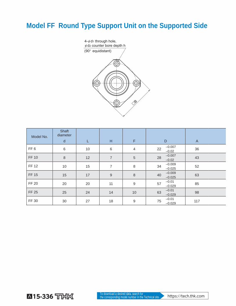
Model FF Round Type Support Unit on the Supported Side
(90° equidistant)
4-φ d1 through hole,φ d2 counter bore depth h
�B
Model No. Shaft
diameter
d L H F D A
FF 6 6 10 6 4 22 –0.007 –0.02 36
FF 10 8 12 7 5 28 –0.007 –0.02 43
FF 12 10 15 7 8 34 –0.009 –0.025 52
FF 15 15 17 9 8 40 –0.009 –0.025 63
FF 20 20 20 11 9 57 –0.01 –0.029 85
FF 25 25 24 14 10 63 –0.01 –0.029 98
FF 30 30 27 18 9 75 –0.01 –0.029 117
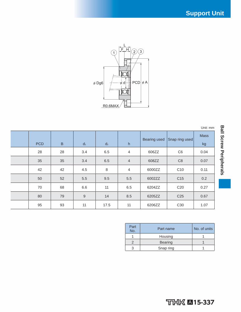
A15-337
Ball Screw
PeripheralsSupport Unit
Part No. Part name No. of units
1 Housing 1 2 Bearing 1 3 Snap ring 1
φ APCD φ dφ Dg6
H F L
1 2 3
R0.6MAX
Unit: mm
Bearing used Snap ring used
Mass
PCD B d 1 d 2 h kg
28 28 3.4 6.5 4 606ZZ C6 0.04
35 35 3.4 6.5 4 608ZZ C8 0.07
42 42 4.5 8 4 6000ZZ C10 0.11
50 52 5.5 9.5 5.5 6002ZZ C15 0.2
70 68 6.6 11 6.5 6204ZZ C20 0.27
80 79 9 14 8.5 6205ZZ C25 0.67
95 93 11 17.5 11 6206ZZ C30 1.07
A15-338 To download a desired data, search for the corresponding model number in the Technical site. https://tech.thk.com
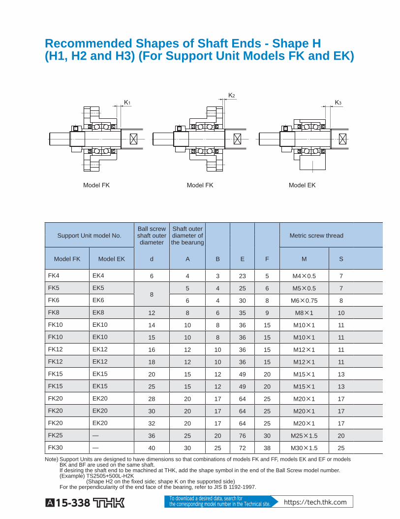
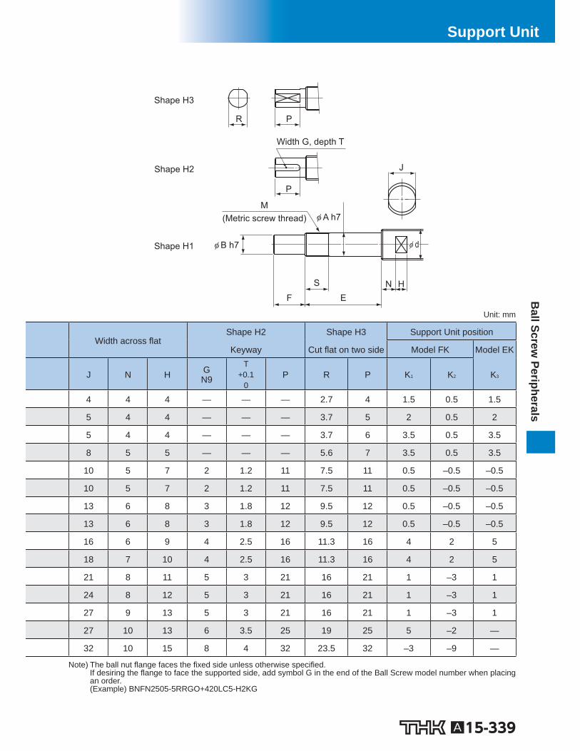
Recommended Shapes of Shaft Ends - Shape H (H1, H2 and H3) (For Support Unit Models FK and EK)
Model EK Model FK Model FK
K1 K2
K3
Support Unit model No. Ball screwshaft outerdiameter
Shaft outerdiameter ofthe bearung
Metric screw thread
Model FK Model EK d A B E F M S
FK4 EK4 6 4 3 23 5 M4×0.5 7
FK5 EK5 8
5 4 25 6 M5×0.5 7
FK6 EK6 6 4 30 8 M6×0.75 8
FK8 EK8 12 8 6 35 9 M8×1 10
FK10 EK10 14 10 8 36 15 M10×1 11
FK10 EK10 15 10 8 36 15 M10×1 11
FK12 EK12 16 12 10 36 15 M12×1 11
FK12 EK12 18 12 10 36 15 M12×1 11
FK15 EK15 20 15 12 49 20 M15×1 13
FK15 EK15 25 15 12 49 20 M15×1 13
FK20 EK20 28 20 17 64 25 M20×1 17
FK20 EK20 30 20 17 64 25 M20×1 17
FK20 EK20 32 20 17 64 25 M20×1 17
FK25 — 36 25 20 76 30 M25×1.5 20
FK30 — 40 30 25 72 38 M30×1.5 25
Note) Support Units are designed to have dimensions so that combinations of models FK and FF, models EK and EF or models BK and BF are used on the same shaft. If desiring the shaft end to be machined at THK, add the shape symbol in the end of the Ball Screw model number. (Example) TS2505+500L-H2K (Shape H2 on the xed side; shape K on the supported side) For the perpendicularity of the end face of the bearing, refer to JIS B 1192-1997.
A15-339
Ball Screw
PeripheralsSupport Unit
Shape H1
Shape H2
Shape H3
Width G, depth T
(Metric screw thread)
S
P R
J
P
F E N H
M
φ B h7
φ A h7
φ d
Unit: mm
Width across at Shape H2 Shape H3 Support Unit position
Keyway Cut at on two side Model FK Model EK
J N H G N9
T +0.1
0 P R P K 1 K 2 K 3
4 4 4 — — — 2.7 4 1.5 0.5 1.5
5 4 4 — — — 3.7 5 2 0.5 2
5 4 4 — — — 3.7 6 3.5 0.5 3.5
8 5 5 — — — 5.6 7 3.5 0.5 3.5
10 5 7 2 1.2 11 7.5 11 0.5 –0.5 –0.5
10 5 7 2 1.2 11 7.5 11 0.5 –0.5 –0.5
13 6 8 3 1.8 12 9.5 12 0.5 –0.5 –0.5
13 6 8 3 1.8 12 9.5 12 0.5 –0.5 –0.5
16 6 9 4 2.5 16 11.3 16 4 2 5
18 7 10 4 2.5 16 11.3 16 4 2 5
21 8 11 5 3 21 16 21 1 –3 1
24 8 12 5 3 21 16 21 1 –3 1
27 9 13 5 3 21 16 21 1 –3 1
27 10 13 6 3.5 25 19 25 5 –2 —
32 10 15 8 4 32 23.5 32 –3 –9 —
Note) The ball nut ange faces the xed side unless otherwise speci ed. If desiring the ange to face the supported side, add symbol G in the end of the Ball Screw model number when placing an order. (Example) BNFN2505-5RRGO+420LC5-H2KG
A15-340 To download a desired data, search for the corresponding model number in the Technical site. https://tech.thk.com
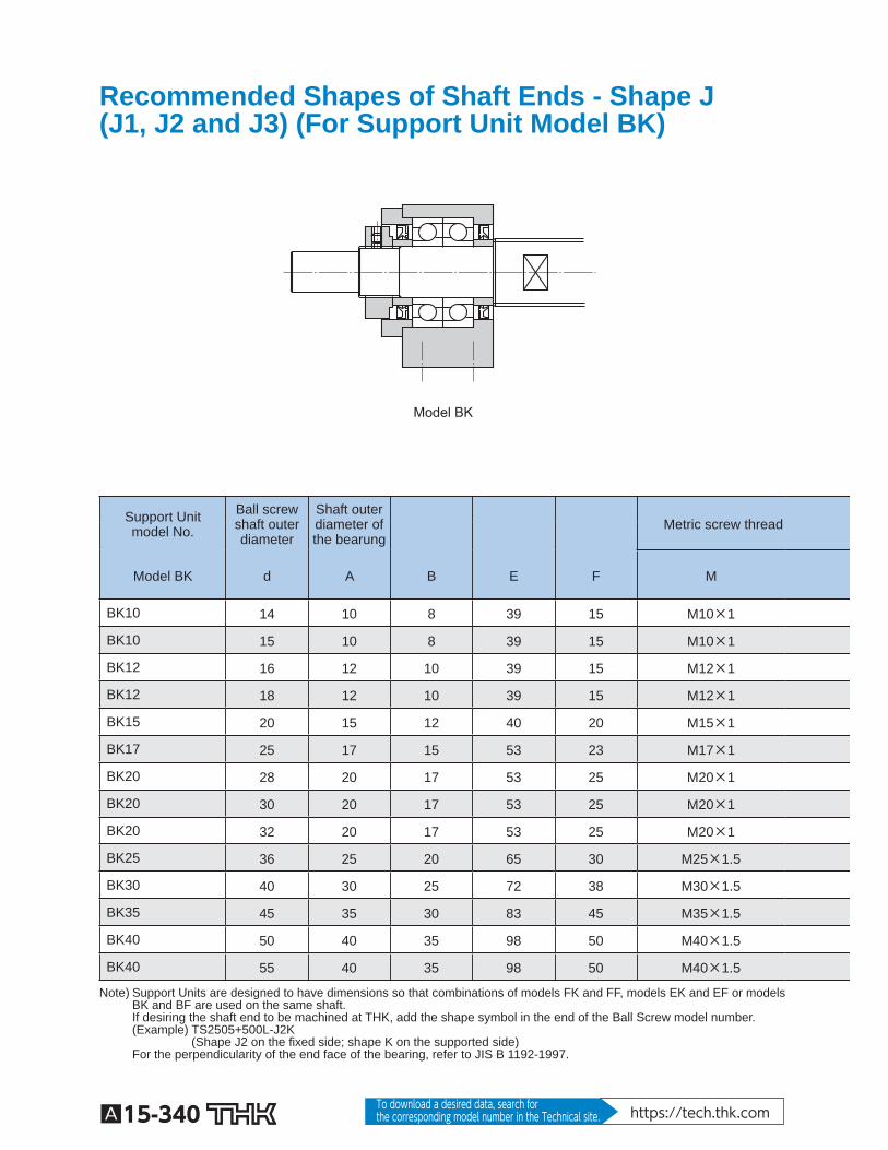
Recommended Shapes of Shaft Ends - Shape J (J1, J2 and J3) (For Support Unit Model BK)
Model BK
Support Unitmodel No.
Ball screwshaft outerdiameter
Shaft outerdiameter ofthe bearung
Metric screw thread
Model BK d A B E F M
BK10 14 10 8 39 15 M10×1
BK10 15 10 8 39 15 M10×1
BK12 16 12 10 39 15 M12×1
BK12 18 12 10 39 15 M12×1
BK15 20 15 12 40 20 M15×1
BK17 25 17 15 53 23 M17×1
BK20 28 20 17 53 25 M20×1
BK20 30 20 17 53 25 M20×1
BK20 32 20 17 53 25 M20×1
BK25 36 25 20 65 30 M25×1.5
BK30 40 30 25 72 38 M30×1.5
BK35 45 35 30 83 45 M35×1.5
BK40 50 40 35 98 50 M40×1.5
BK40 55 40 35 98 50 M40×1.5
Note) Support Units are designed to have dimensions so that combinations of models FK and FF, models EK and EF or models BK and BF are used on the same shaft. If desiring the shaft end to be machined at THK, add the shape symbol in the end of the Ball Screw model number. (Example) TS2505+500L-J2K (Shape J2 on the xed side; shape K on the supported side) For the perpendicularity of the end face of the bearing, refer to JIS B 1192-1997.
A15-341
Ball Screw
PeripheralsSupport Unit
Shape J1
Shape J2
Shape J3
(Metric screw thread)
Width G, depth T
F
S
P R
J
E
N H
φ d
M
P
φ B h7
φ A h7
Unit: mm
Width across at
Shape J2 Shape J3
Keyway Cut at on two side
S J N H G N9
T +0.1
0 P R P
16 10 5 7 2 1.2 11 7.5 11
16 10 5 7 2 1.2 11 7.5 11
14 13 6 8 3 1.8 12 9.5 12
14 13 6 8 3 1.8 12 9.5 12
12 16 6 9 4 2.5 16 11.3 16
17 18 7 10 5 3 21 14.3 21
15 21 8 11 5 3 21 16 21
15 24 8 12 5 3 21 16 21
15 27 9 13 5 3 21 16 21
18 27 10 13 6 3.5 25 19 25
25 32 10 15 8 4 32 23.5 32
28 36 12 15 8 4 40 28.5 40
35 41 14 19 10 5 45 33 45
35 46 14 20 10 5 45 33 45
Note) The ball nut ange faces the xed side unless otherwise speci ed. If desiring the ange to face the supported side, add symbol G in the end of the Ball Screw model number when placing an order. (Example) BNFN2505-5RRGO+420LC5-J2KG
A15-342 To download a desired data, search for the corresponding model number in the Technical site. https://tech.thk.com
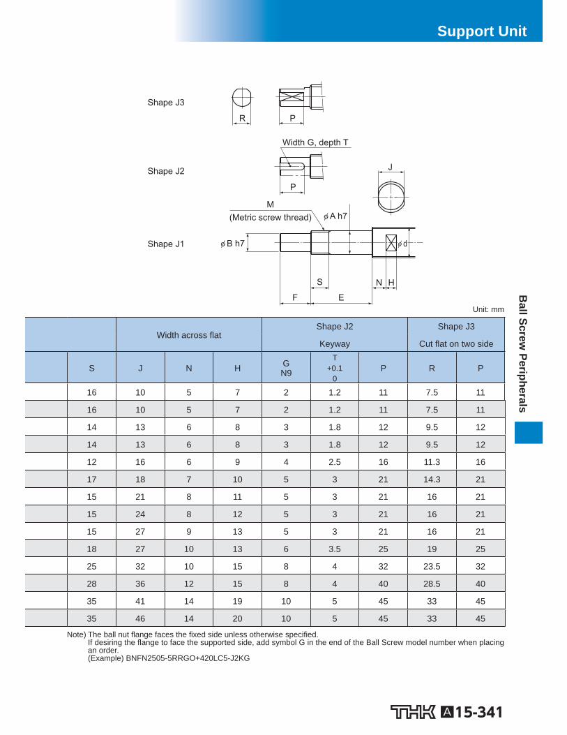
Recommended Shapes of Shaft Ends - Shape K (For Support Unit Models FF, EF and BF)
Model EF
Model BF Model FF Model FF
Support Unit model No. Ball screw shaftouter diameter
Shaft outer diameterof the bearung
Model FF Model EF Model BF d A
FF10 EF10 BF10 14 8
FF10 EF10 BF10 15 8
FF12 EF12 BF12 16 10
FF12 EF12 BF12 18 10
FF15 EF15 BF15 20 15
FF15 EF15 BF15 25
15
— — BF17 * 17
FF20 EF20 BF20 ** 28 20
FF20 EF20 BF20 ** 30 20
FF20 EF20 BF20 ** 32 20
FF25 — BF25 36 25
FF30 — BF30 40 30
— — BF35 45 35
— — BF40 50 40
— — BF40 55 40
Note) Support Units are designed to have dimensions so that combinations of models FK and FF, models EK and EF or models BK and BF are used on the same shaft. If desiring the shaft end to be machined at THK, add the shape symbol in the end of the Ball Screw model number. (Example) TS2505+500L-H2K (Shape H2 on the xed side; shape K on the supported side) For the perpendicularity of the end face of the bearing, refer to JIS B 1192-1997.
A15-343
Ball Screw
PeripheralsSupport Unit
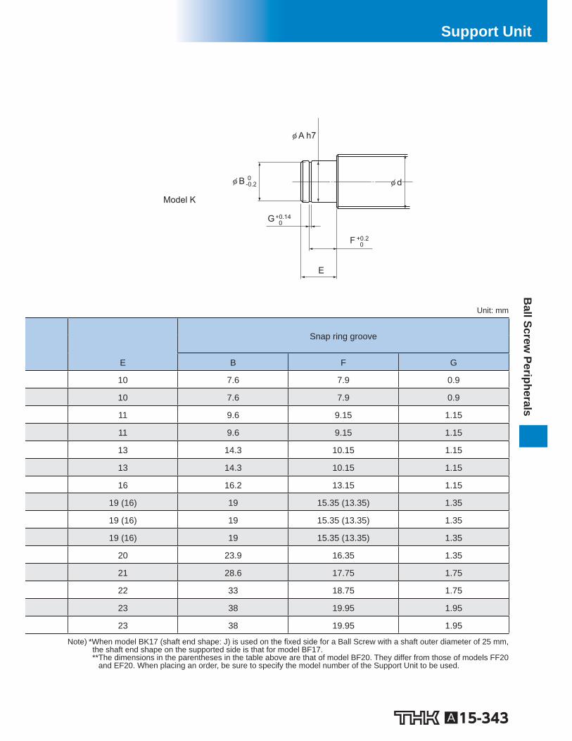
Model K
G +0.14 0
F
E
φ d
φ A h7
φ B
+0.2 0
0 -0.2
Unit: mm
Snap ring groove
E B F G
10 7.6 7.9 0.9
10 7.6 7.9 0.9
11 9.6 9.15 1.15
11 9.6 9.15 1.15
13 14.3 10.15 1.15
13 14.3 10.15 1.15
16 16.2 13.15 1.15
19 (16) 19 15.35 (13.35) 1.35
19 (16) 19 15.35 (13.35) 1.35
19 (16) 19 15.35 (13.35) 1.35
20 23.9 16.35 1.35
21 28.6 17.75 1.75
22 33 18.75 1.75
23 38 19.95 1.95
23 38 19.95 1.95
Note) *When model BK17 (shaft end shape: J) is used on the xed side for a Ball Screw with a shaft outer diameter of 25 mm, the shaft end shape on the supported side is that for model BF17. **The dimensions in the parentheses in the table above are that of model BF20. They differ from those of models FF20
and EF20. When placing an order, be sure to specify the model number of the Support Unit to be used.