ball screw selection and calculations - university of utahme7960/lectures/topic4-ball... ·...
TRANSCRIPT
1
ME EN 7960 – Precision Machine Design – Ball Screw Calculations 4-1
Ball Screw Selection and Calculations
ME EN 7960 – Precision Machine DesignTopic 4
ME EN 7960 – Precision Machine Design – Ball Screw Calculations 4-2
Ball Screw Selection Criteria
Maximum Rotational Speed
Resonance (bending) of threaded shaftDN value
Applied LoadThrust forceRequired torque
Stiffness
Ball Screw Selection
Ball Screw LifeBasic dynamic load rating
Accuracy
2
ME EN 7960 – Precision Machine Design – Ball Screw Calculations 4-3
Based on Load
• A ball screw transforms rotational motion into translational motion. As a result, the shaft is subject to loads:– Thrust force (the sum of all external forces such as machining
load, gravity, friction, inertial forces, etc.).– Torque required to generate the thrust force.
ME EN 7960 – Precision Machine Design – Ball Screw Calculations 4-4
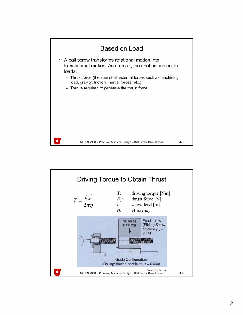
Driving Torque to Obtain Thrust
πη2lFT a=
T: driving torque [Nm]Fa: thrust force [N]l: screw lead [m]η: efficiency
Source: THK Co., Ltd.
3
ME EN 7960 – Precision Machine Design – Ball Screw Calculations 4-5
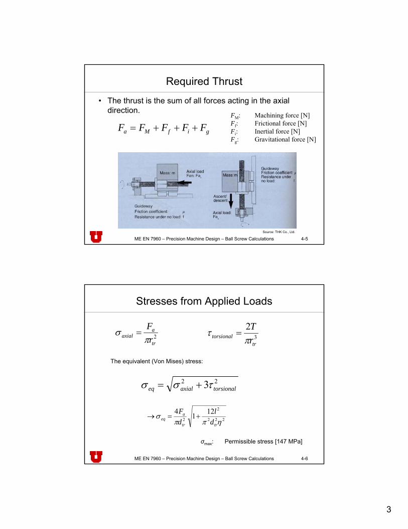
Required Thrust
• The thrust is the sum of all forces acting in the axial direction.
gifMa FFFFF +++=FM: Machining force [N]Ff: Frictional force [N]Fi: Inertial force [N]Fg: Gravitational force [N]
Source: THK Co., Ltd.
ME EN 7960 – Precision Machine Design – Ball Screw Calculations 4-6
Stresses from Applied Loads
2tr
aaxial r
Fπ
σ = 3
2
trtorsional r
Tπ
τ =
The equivalent (Von Mises) stress:
22 3 torsionalaxialeq τσσ +=
222
2
2
1214ηππ
σtrtr
aeq d
ldF
+=→
σmax: Permissible stress [147 MPa]
4
ME EN 7960 – Precision Machine Design – Ball Screw Calculations 4-7
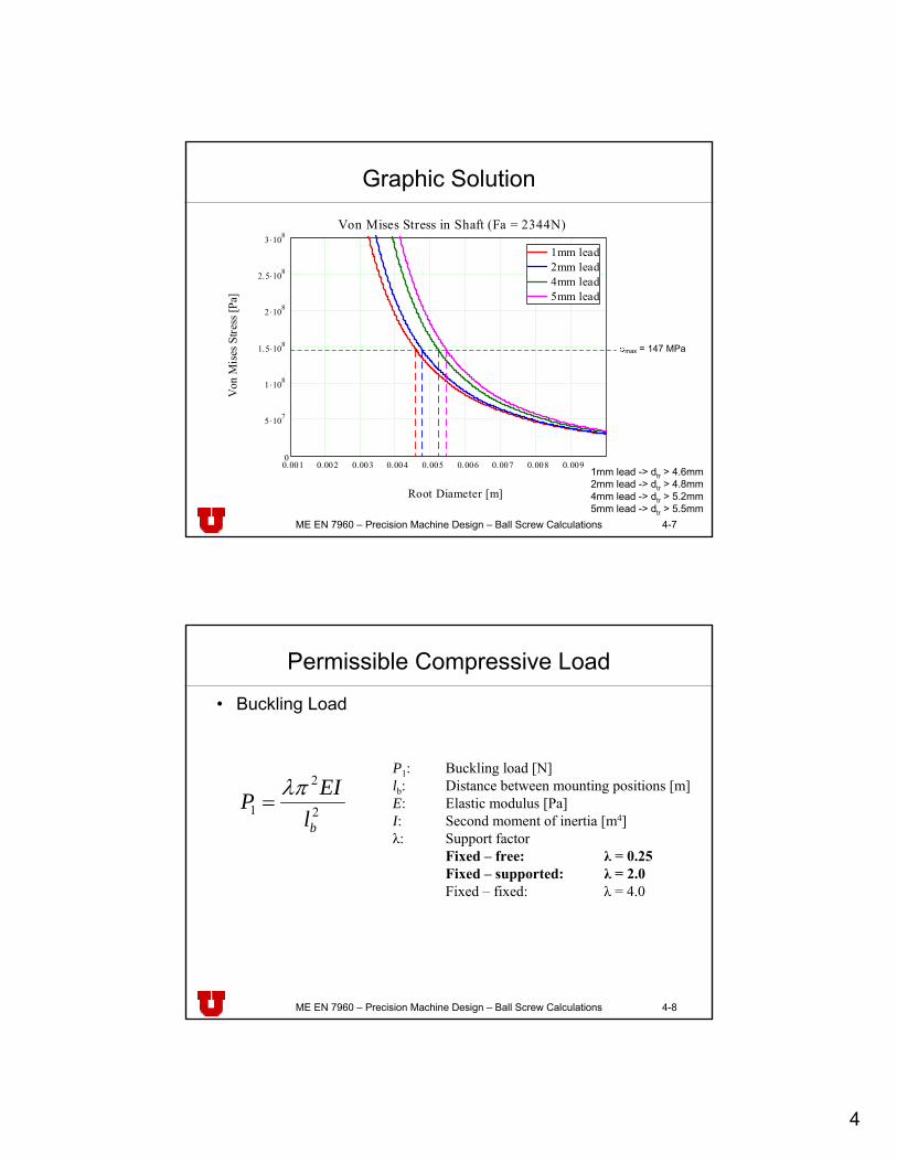
Graphic Solution
0.001 0.002 0.003 0.004 0.005 0.006 0.007 0.008 0.0090
5 .107
1 .108
1.5 .108
2 .108
2.5 .108
3 .108
1mm lead2mm lead4mm lead5mm lead
Von Mises Stress in Shaft (Fa = 2344N)
Root Diameter [m]
Von
Mis
es S
tress
[Pa]
max = 147 MPa
1mm lead -> dtr > 4.6mm2mm lead -> dtr > 4.8mm4mm lead -> dtr > 5.2mm5mm lead -> dtr > 5.5mm
ME EN 7960 – Precision Machine Design – Ball Screw Calculations 4-8
Permissible Compressive Load
• Buckling Load
2
2
1blEIP λπ
=
P1: Buckling load [N]lb: Distance between mounting positions [m]E: Elastic modulus [Pa]I: Second moment of inertia [m4]λ: Support factor
Fixed – free: λ = 0.25Fixed – supported: λ = 2.0Fixed – fixed: λ = 4.0
5
ME EN 7960 – Precision Machine Design – Ball Screw Calculations 4-9
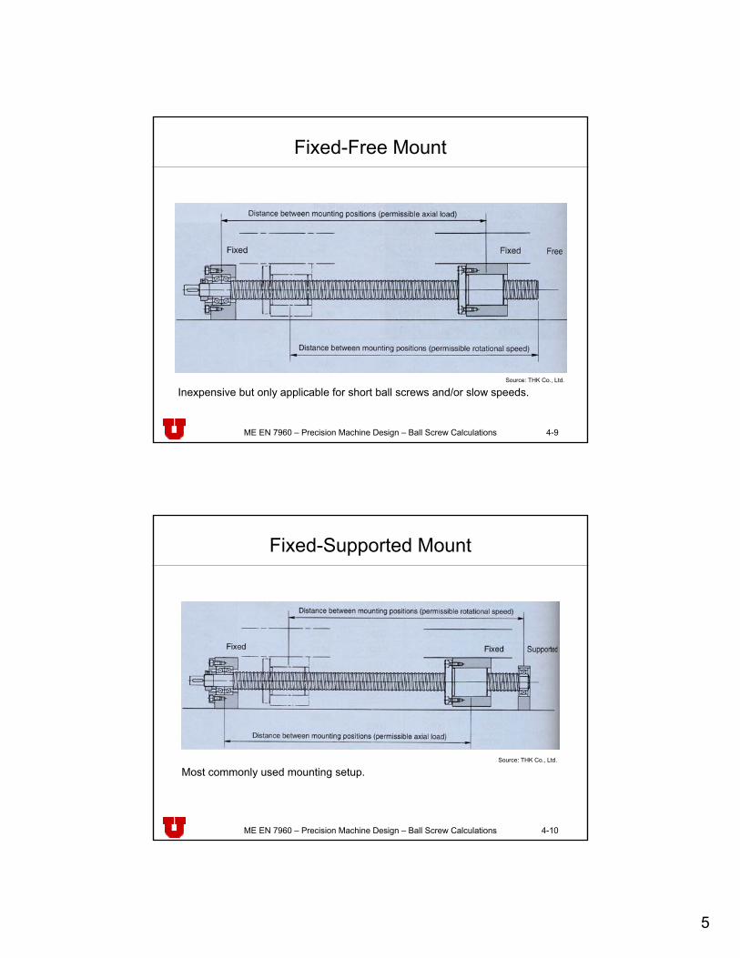
Fixed-Free Mount
Source: THK Co., Ltd.
Inexpensive but only applicable for short ball screws and/or slow speeds.
ME EN 7960 – Precision Machine Design – Ball Screw Calculations 4-10
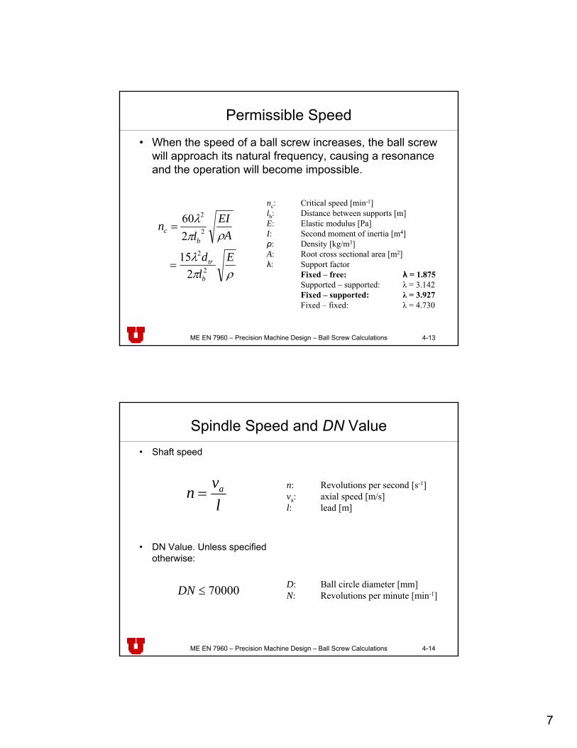
Fixed-Supported Mount
Source: THK Co., Ltd.
Most commonly used mounting setup.

6
ME EN 7960 – Precision Machine Design – Ball Screw Calculations 4-11
Fixed-Fixed Mount
Source: THK Co., Ltd.
Overconstrained mounting setup for applications where high stiffness, accuracy, and high shaft speed is required. Ball screw needs to be pre-stretched to avoid buckling in the case of thermal expansion.
ME EN 7960 – Precision Machine Design – Ball Screw Calculations 4-12
Basic Static Load Rating Coa
– When ball screws are subjected to excessive loads in static condition (non rotating shaft), local permanent deformations arecaused between the track surface and the steel balls.
– When the amount of this permanent deformation exceeds a certain degree, smooth movement will be impaired.
asoa FfC ≥Coa: Basic static load rating [N, kgf, lbf]fs: Static safety factorFa: Load on shaft in axial direction [N, kgf, lbf]
2.0 – 3.0Operation with impacts and vibrations1.0 – 2.0Normal operation
fs (lower limit)Use conditions
7
ME EN 7960 – Precision Machine Design – Ball Screw Calculations 4-13
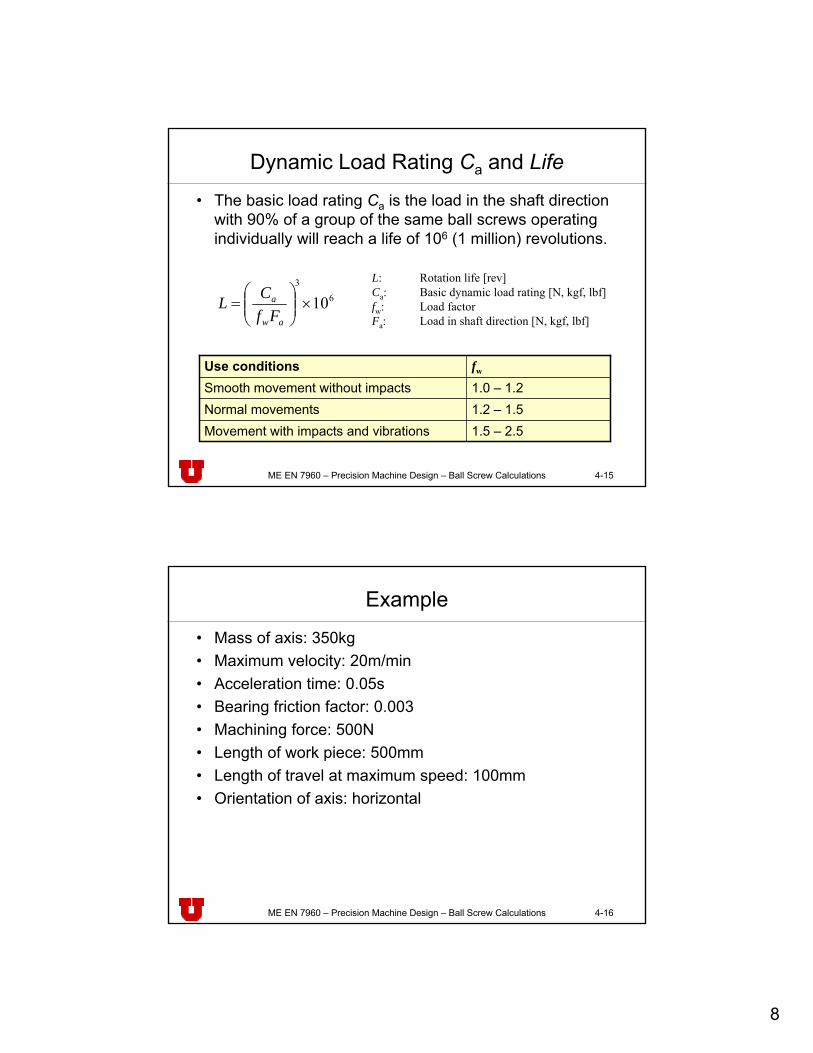
Permissible Speed
• When the speed of a ball screw increases, the ball screw will approach its natural frequency, causing a resonance and the operation will become impossible.
ρπλ
ρπλ
Eld
AEI
ln
b
tr
bc
2
2
2
2
215
260
=
=
nc: Critical speed [min-1]lb: Distance between supports [m]E: Elastic modulus [Pa]I: Second moment of inertia [m4]ρ: Density [kg/m3]A: Root cross sectional area [m2]λ: Support factor
Fixed – free: λ = 1.875Supported – supported: λ = 3.142Fixed – supported: λ = 3.927Fixed – fixed: λ = 4.730
ME EN 7960 – Precision Machine Design – Ball Screw Calculations 4-14
Spindle Speed and DN Value• Shaft speed
• DN Value. Unless specified otherwise:
70000≤DN D: Ball circle diameter [mm]N: Revolutions per minute [min-1]
lvn a= n: Revolutions per second [s-1]
va: axial speed [m/s]l: lead [m]
8
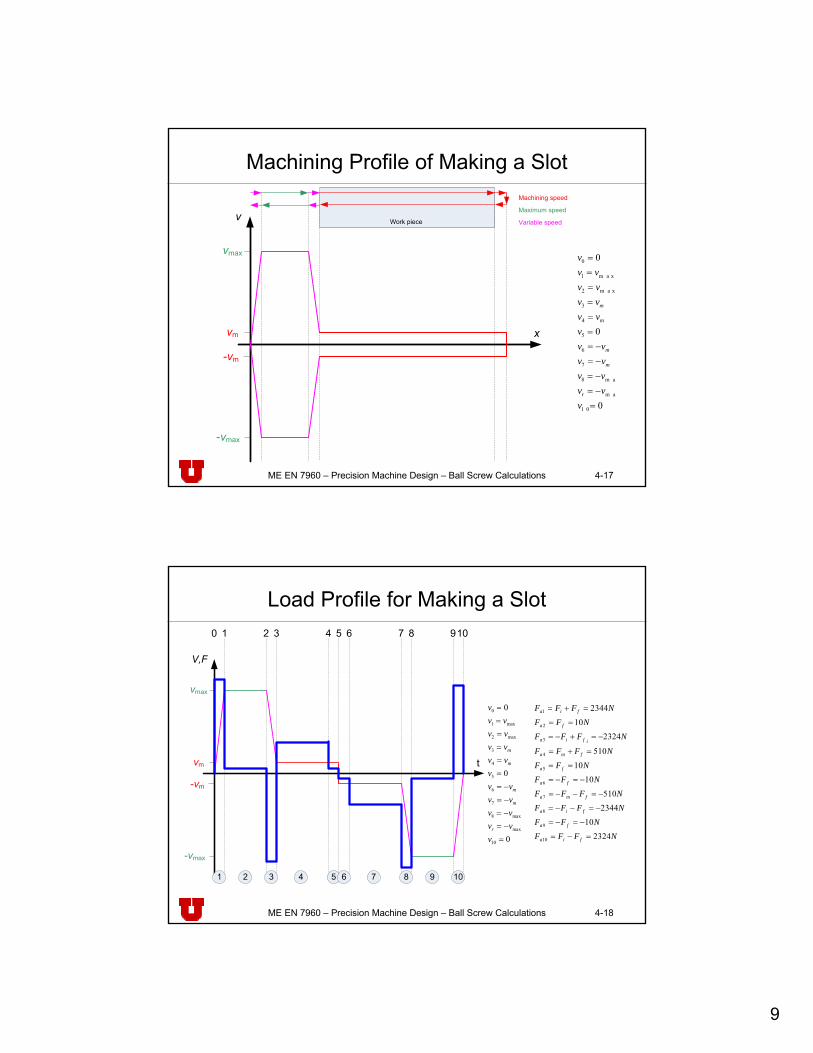
ME EN 7960 – Precision Machine Design – Ball Screw Calculations 4-15
Dynamic Load Rating Ca and Life
• The basic load rating Ca is the load in the shaft direction with 90% of a group of the same ball screws operating individually will reach a life of 106 (1 million) revolutions.
63
10×⎟⎟⎠
⎞⎜⎜⎝
⎛=
aw
a
FfCL
L: Rotation life [rev]Ca: Basic dynamic load rating [N, kgf, lbf]fw: Load factorFa: Load in shaft direction [N, kgf, lbf]
1.5 – 2.5Movement with impacts and vibrations1.2 – 1.5Normal movements1.0 – 1.2Smooth movement without impactsfwUse conditions
ME EN 7960 – Precision Machine Design – Ball Screw Calculations 4-16
Example
• Mass of axis: 350kg• Maximum velocity: 20m/min• Acceleration time: 0.05s• Bearing friction factor: 0.003• Machining force: 500N• Length of work piece: 500mm• Length of travel at maximum speed: 100mm• Orientation of axis: horizontal
9
ME EN 7960 – Precision Machine Design – Ball Screw Calculations 4-17
Machining Profile of Making a Slot
0
0
0
1 0
m a x
m a x8
7
6
5
4
3
m a x2
m a x1
0
=−=−=−=−=
======
vvvvvvvvv
vvvvvvvvv
v
r
m
m
m
m
Machining speed
Maximum speed
Variable speedWork piece
vmax
-vmax
-vm
vm
v
x
ME EN 7960 – Precision Machine Design – Ball Screw Calculations 4-18
Load Profile for Making a Slot
0
0
0
10
max
max8
7
6
5
4
3
max2
max1
0
=−=−=−=−=
======
vvvvvvvvv
vvvvvvvvv
v
r
m
m
m
m
vmax
-vmax
-vm
vm
V,F
t
0 1 2 3 4 5 6 7 8 910
101 2 3 4 5 6 7 8 9
NFFF
NFF
NFFF
NFFF
NFFNFF
NFFF
NFFF
NFF
NFFF
fia
fa
fia
fma
fa
fa
fma
ifia
fa
fia
2324
10
2344
510
1010
510
2324
10
2344
10
9
8
7
6
5
4
3
2
1
=−=
−=−=
−=−−=
−=−−=
−=−=
==
=+=
−=+−=
==
=+=
10
ME EN 7960 – Precision Machine Design – Ball Screw Calculations 4-19
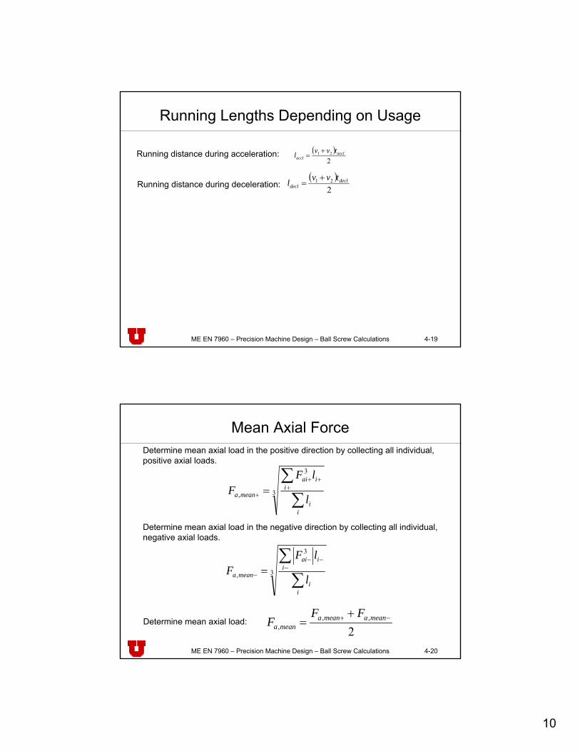
Running Lengths Depending on Usage
( )2
21 acclaccl
tvvl +=Running distance during acceleration:
Running distance during deceleration:( )
221 decl
decltvvl +
=
ME EN 7960 – Precision Machine Design – Ball Screw Calculations 4-20
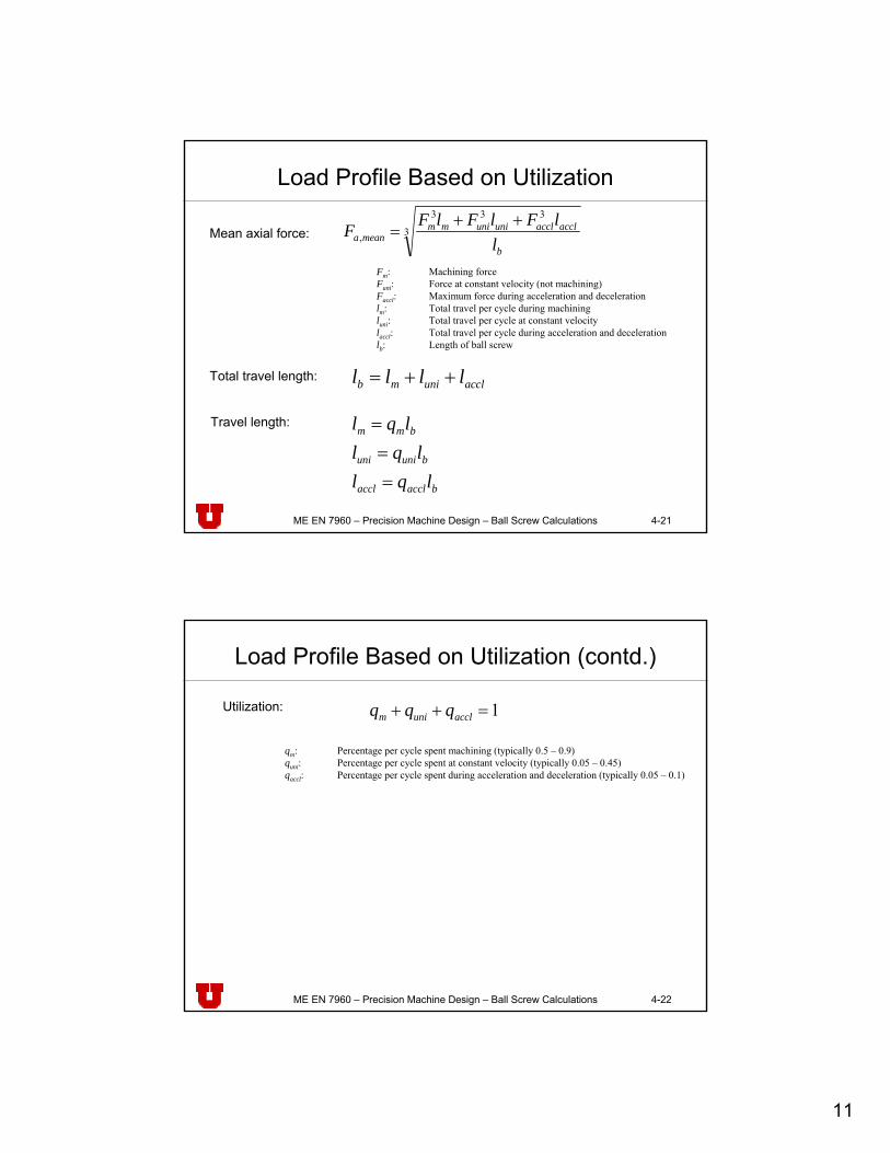
Mean Axial ForceDetermine mean axial load in the positive direction by collecting all individual, positive axial loads.
3
3
, ∑∑+
++
+ =
ii
iiai
meana l
lFF
Determine mean axial load in the negative direction by collecting all individual, negative axial loads.
3
3
, ∑∑−
−−
− =
ii
iiai
meana l
lFF
Determine mean axial load:2
,,,
−+ += meanameanameana
FFF
11
ME EN 7960 – Precision Machine Design – Ball Screw Calculations 4-21
Load Profile Based on Utilization
3
333
,b
acclaccluniunimmmeana l
lFlFlFF ++=Mean axial force:
Fm: Machining forceFuni: Force at constant velocity (not machining)Faccl: Maximum force during acceleration and decelerationlm: Total travel per cycle during machiningluni: Total travel per cycle at constant velocitylaccl: Total travel per cycle during acceleration and decelerationlb: Length of ball screw
Total travel length: acclunimb llll ++=
Travel length:
bacclaccl
buniuni
bmm
lqllql
lql
===
ME EN 7960 – Precision Machine Design – Ball Screw Calculations 4-22
Load Profile Based on Utilization (contd.)
qm: Percentage per cycle spent machining (typically 0.5 – 0.9)quni: Percentage per cycle spent at constant velocity (typically 0.05 – 0.45)qaccl: Percentage per cycle spent during acceleration and deceleration (typically 0.05 – 0.1)
Utilization: 1=++ acclunim qqq
12
ME EN 7960 – Precision Machine Design – Ball Screw Calculations 4-23
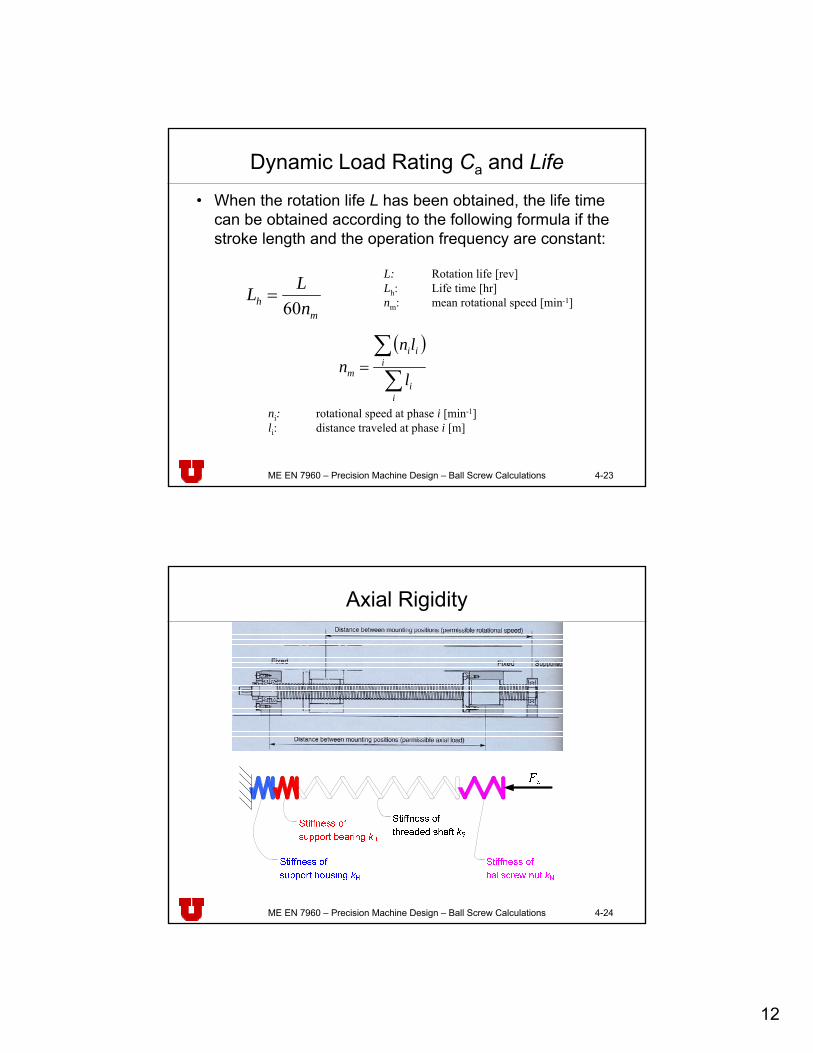
Dynamic Load Rating Ca and Life
• When the rotation life L has been obtained, the life time can be obtained according to the following formula if the stroke length and the operation frequency are constant:
mh n
LL60
=L: Rotation life [rev]Lh: Life time [hr]nm: mean rotational speed [min-1]
( )
∑∑
=
ii
iii
m l
lnn
ni: rotational speed at phase i [min-1]li: distance traveled at phase i [m]
ME EN 7960 – Precision Machine Design – Ball Screw Calculations 4-24
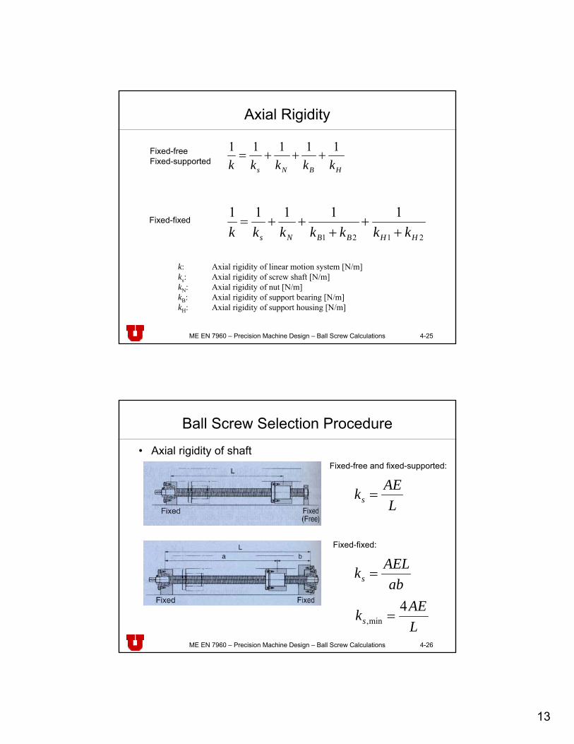
Axial Rigidity
13
ME EN 7960 – Precision Machine Design – Ball Screw Calculations 4-25
Axial Rigidity
HBNs kkkkk11111
+++=
k: Axial rigidity of linear motion system [N/m]ks: Axial rigidity of screw shaft [N/m]kN: Axial rigidity of nut [N/m]kB: Axial rigidity of support bearing [N/m]kH: Axial rigidity of support housing [N/m]
2121
11111
HHBBNs kkkkkkk ++
+++=
Fixed-freeFixed-supported
Fixed-fixed
ME EN 7960 – Precision Machine Design – Ball Screw Calculations 4-26
Ball Screw Selection Procedure
• Axial rigidity of shaftFixed-free and fixed-supported:
LAEks =
Fixed-fixed:
abAELks =
LAEks
4min, =
14
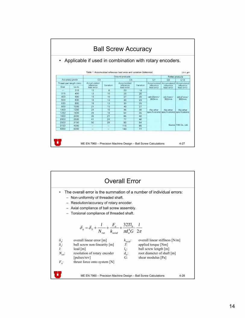
ME EN 7960 – Precision Machine Design – Ball Screw Calculations 4-27
Ball Screw Accuracy
• Applicable if used in combination with rotary encoders.
Source: THK Co., Ltd.
ME EN 7960 – Precision Machine Design – Ball Screw Calculations 4-28
Overall Error• The overall error is the summation of a number of individual errors:
– Non-uniformity of threaded shaft.– Resolution/accuracy of rotary encoder.– Axial compliance of ball screw assembly.– Torsional compliance of threaded shaft.
ππδδ
232
4
lGd
TlkF
Nl
tr
b
axial
a
rotSa ⋅+++=
δa: overall linear error [m]δs: ball screw non-linearity [m]l: lead [m]Nrot: resolution of rotary encoder
[pulses/rev]Fa: thrust force onto system [N]
kaxial: overall linear stiffness [N/m]Τ: applied torque [Nm]lb: ball screw length [m]dtr: root diameter of shaft [m]G: shear modulus [Pa]