bac 2009 ecat - emerson swan, inc. · pdf fileg t o w e r s fxt coolingtowers ... • no b...
TRANSCRIPT

Co
olin
gT
ow
ersFXTCooling Towers
ProductDetailProduct Introduction . . . . . . . . . . . . . . . . . . . . . . . . . . . . . . . . . .D51
Benefits . . . . . . . . . . . . . . . . . . . . . . . . . . . . . . . . . . . . . . . . . . . . . . .D53
Construction Details . . . . . . . . . . . . . . . . . . . . . . . . . . . . . . . . . . .D55
Accessories . . . . . . . . . . . . . . . . . . . . . . . . . . . . . . . . . . . . . . . . . . . .D57
Structural Support . . . . . . . . . . . . . . . . . . . . . . . . . . . . . . . . . . . . .D58
Engineering Data . . . . . . . . . . . . . . . . . . . . . . . . . . . . . . . . . . . . .D59
Engineering Specifications . . . . . . . . . . . . . . . . . . . . . . . . . . . . .D61
Engineering Considerations . . . . . . . . . . . . . . . . . . . . . . . . . . .D105
D50

Spotlight
D51

D52
Low Energy ConsumptionLow Installed CostEasy MaintenanceLong Service Life
FX
T
D53 Baltimore Aircoil Company
Low Energy Consumption• Evaporative cooling equipment minimizes the energy consumption of the entire system because itprovides lower condenser water temperatures. Owners save money while conserving natural resourcesand reducing environmental impact.
• The FXT provides the heat rejection required at the lowest possible energy input via:
• High efficiency, low horsepower axial fans
• High efficiency BACross® Fill, which provides maximum air/water contact timeat low air pressure drops
• Premium efficient/VFD duty motors are standard.
• Variable frequency drives (optional) (see page K1 for details.)
• All units meet or exceed ASHRAE Standard 90.1 energy efficiency requirements.
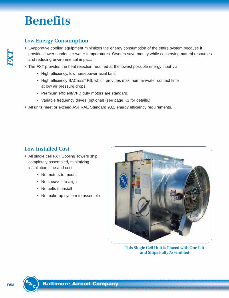
Low Installed Cost• All single cell FXT Cooling Towers shipcompletely assembled, minimizinginstallation time and cost:
• No motors to mount
• No sheaves to align
• No belts to install
• No make-up system to assemble
Benefits
This Single Cell Unit is Placed with One Liftand Ships Fully Assembled

Co
olin
gT
ow
ers
D54...because temperature matters™
Easy Maintenance• Easy access – The interior of the unit isaccessible through a circular access doorfor adjusting the float valve, cleaning the
strainer, or flushing the basin.
• Motor locatio n – The fan motor islocated on the exterior of the unit for easymaintenance and belt adjustment. On mostmodels, a single threaded bolt and nutassembly further simplifies belt adjustment.
• Easy lubr icatio n – Fittings for extendedlubrication lines are provided as standardon the exterior of the unit for bearing lubrication.
Long Service Life• Materi als of con stru cti on – Various materials are available to meet the corrosion resistance, unitoperating life, and budgetary requirements of any project (see page D56 for construction options).
Circular Access Door
The Fan Motor is Easily Accessible at the Base of the Unit’s Exterior
FX
T
D55 Baltimore Aircoil Company
Construction Details
1
2
3
4
5
6
7
8
9
10

Co
olin
gT
ow
ers
D56...because temperature matters™
Construction Options
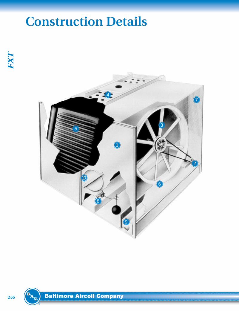
Heavy-Duty Construction• G-235 (Z700 metric) hot-dip galvanizedsteel panels
Fan Drive System• Direct drive: Models FXT-6 through FXT-20
• V-belt drive: Models FXT-26 and above
• Heavy-duty bearings L10 40,000 hours(280,000 hour average life)
• Extended lubrication lines
• Premium efficient/VFDduty motors as standard
• 5-year motor and drive warranty
Low Horsepower Axial Fan(s)• High efficiency
• Corrosion resistant
Water Distribution System• Non-clog nozzles
• Low pump head gravity distribution basin
• Steel distribution covers (not shown)
BACross®Fill with IntegralDrift Eliminators
• High efficiency heat transfer surface
• Polyvinyl chloride (PVC)
• Impervious to rot, decay and biological attack
• Flame spread rating of 5 per ASTM E84
Air Inlet Cylinder• Streamlines air entry for maximum efficiency
Inlet Screens• Protection from moving parts• Easily removed for access to fans, bearings,motor and drives
Water Make-upValve Assembly• Corrosion resistant float valve
• Large diameter plastic float
Strainer• Anti-vortexing design to preventair entrainment
Access Door• Interior of the unit is easily accesible
• Standard Construction:Panels and structural elements are constructed of G-235 (Z700 metric) hot-dip galvanized steel.
• Opt ional Therm osetti ng Hybrid Polymer:A thermosetting hybrid polymer coating used to extend equipment life, is applied to select hot-dipgalvanized steel components of the cooling tower. The thermosetting hybrid polymer has beentested to withstand 6000 hours in a 5% salt spray without blistering, chipping, or loss of adhesion.
• Opt ional Stainless Steel Cold Water Basin:A Type 304 stainless steel cold water basin is available on models FXT-26 thru FXT-257.
• Opt ional Stainless Steel Cons truction:All steel panels and structural elements are constructed of Type 304 stainless steel.
See page M20 for more details on the materials described above.
1
2
3
4
5
6
7
8
9
10

FX
T
D57 Baltimore Aircoil Company
Vibration Cutout SwitchA factory mounted vibration cutout switch is available to effectively protect against equipment failure dueto excessive vibration of the mechanical equipment system. BAC can provide either a mechanical orsolid-state electronic vibration cutout switch in a NEMA 4 enclosure to ensure reliable protection.Additional contacts can be provided on either switch type to activate an alarm.
Basin HeatersCooling towers exposed to below freezing ambient temperatures require protection to prevent freezing ofthe water in the cold water basin when the unit is idle. Factory-installed electric immersion heaters, whichmaintain +40°F (4.4°C) water temperature, are a simple and inexpensive way of providing such protection.
Heater kW Data
ElectricWater Level Control PackageThe electric water level control replaces the standard mechanicalmake-up valve when a more precise water level control is required.This package consists of a conductance-actuated level controlmounted in the basin and a solenoid activated valve in the make-upwater line. The valve is slow closing to minimize water hammer.
High Temperature FillIf operation above 125°F (51.7°C) is anticipated, an optional hightemperature fill material is available which increases the maximumallowable entering water temperature to 140°F (60.0°C).
Discharge ScreensWire mesh screens are available to cover the discharge of the tower to prevent debris from entering theeliminators and cold water basin.
Discharge Air TurningVanesAir turning vanes are available to direct the discharge air up and away from the unit. The turning vanes areinstalled at the factory on the discharge of the tower and require no increase in fan motor horsepower.
Equipment ControlsBAC control panels are specifically designed to work seamlessly with all BAC units and engineered tomeet your particular application. For more information on BAC Equipment Controls, see section K.
Factory Mutual Approval construction is available as an option.
Accessories
Model Numbers
0˚F (-17.8˚C) Ambient Heaters -20˚F (-28.9˚C) Ambient Heaters
Number of Heaters kW per Heater Number of Heaters kW per Heater
FXT - 6, 7.5 1 2 1 2
FXT - 11 to 20 1 2 1 3
FXT - 26 to 68 1 3 1 5
FXT - 74 to 95 1 4 1 6
FXT - 115 to 136 2 3 2 5
FXT - 160 to 257 2 4 2 6
ElectricWater Level Control

Co
olin
gT
ow
ers
D58...because temperature matters™
The recommended support arrangement for the FXT Cooling Tower consists of parallel “I” beamspositioned as shown in the drawings. Besides providing adequate support, the steel also serves toraise the unit above any solid foundation to assure access to the bottom of the tower. FXT towers mayalso be supported on columns at the anchor bolt locations shown, if required. A minimum bearingsurface of 6” x 6” inches square (152.4mm x 152.4mm) must be provided under each of theconcentrated load points.
Structural Support
Notes:1. Support beams and anchor bolts are to be selected andinstalled by others.
2. All support steel must be level at the top.
3. The BAC standard vibration isolation rail package is designedfor support Plan A.
4. When determining the length of the supporting steel, allow for thelength of the vibration isolation rails as they are sometimes longerthan the cooling tower dimensions shown.
5. Operating weight is based on the water level in cold water basin atoverflow height.
Model Number
Weight (lbs)
L W P1 P2Shipping OperatingFXT - 6 370 980 1’ 3” 5’ 1” 264 226
FXT - 7.5 370 980 1’ 3” 5’ 1” 264 226
FXT - 11 470 1,420 2’ 5’ 1” 369 341
FXT - 16 570 1,330 2’ 5’ 1” 372 293
FXT - 20 590 1,350 2’ 5’ 1” 378 297
FXT - 26 940 2,080 3’ 6” 5’ 1” 624 416
FXT - 30 950 2,090 3’ 6” 5’ 1” 627 418
FXT - 33 950 2,090 3’ 6” 5’ 1” 627 418
FXT - 38 1,000 2,420 3’ 6” 5’ 1” 726 484
FXT - 42 1,000 2,420 3’ 6” 5’ 1” 726 484
FXT - 47 1,020 2,440 3’ 6” 5’ 1” 732 488
FXT - 58 1,220 3,140 5’ 5’ 1” 989 581
FXT - 68 1,230 2,150 5’ 5’ 1” 992 583
FXT - 74 1,720 4,230 5’ 7’ 1-7/8” 1,163 952
FXT - 87 1,730 4,240 5’ 7’ 1-7/8” 1,166 954
FXT - 95 1,770 4,280 5’ 7’ 1-7/8” 1,178 962
FXT - 115 2,220 6,080 8’ 7’ 1-7/8” 1,672 1,368
FXT - 130 2,260 6,120 8’ 7’ 1-7/8” 1,683 1,377
FXT - 136 2,300 6,160 8’ 7’ 1-7/8” 1,695 1,385
FXT - 160 2,880 8,030 11’ 7’ 1-7/8” 2,208 1,807
FXT - 175 2,920 8,070 11’ 7’ 1-7/8” 2,219 1,816
FXT - 192 2,970 8,120 11’ 7’ 1-7/8” 2,234 1,826
FXT - 216 3,560 9,420 11’ 7’ 1-7/8” 2,543 2,167
FXT - 240 3,610 9,470 11’ 7’ 1-7/8” 2,557 2,178
FXT - 257 3,630 9,490 11’ 7’ 1-7/8” 2,563 2,182

FX
T
D59 Baltimore Aircoil Company
Do not use for constructi on. Refer to factory certified dimensions. This handbook includes data currentat the time of publication, which should be reconfirmed at the time of purchase. Up-to-date engineeringdata, free product selection software, and more can be found at www.Balt imoreAirc oil.com .
Engineering Data
Notes :1. Unless otherwise indicated, all connections 4” and smaller are MPT and connections 6” and larger are beveled for welding.
2. Operating weight is based on the water level in cold water basin at overflow height.
3. Nominal tons of cooling represents the capability to cool 3 GPM of water from a 95°F entering water temperature to an 85°F leaving watertemperature at a 78°F entering wet-bulb temperature.
ModelNumber
NominalTonnage Motor HP
Airflow(CFM)
Dimensions Weights (lbs) Connection Sizes
L W H A B C Operating Shipping Inlet Outlet
FXT - 6 6 1/3 2,400 2’ 0-1/8” 6’ 9-3/8” 4’ 7-7/8” 1’ 10-5/8” 7” 1’ 980 370 3” 3”
FXT - 7.5 7.5 1/2 3,000 2’ 0-1/8” 6’ 9-3/8” 4’ 7-7/8” 1’ 10-5/8” 7” 1’ 980 370 3” 3”
FXT - 11 11 1/2 4,400 3’ 0-1/8” 6’ 9-7/8” 4’ 7-7/8” 1’ 10-5/8” 7” 1’ 6” 1,420 470 3” 3”
FXT - 16 16 1/2 5,700 3’ 0-1/8” 6’ 10-7/8” 5’ 11-7/8” 1’ 7-3/4” 7 1/2” 1’ 6” 1,330 570 4” 4”
FXT - 20 20 1 7,100 3’ 0-1/8” 6’ 10-7/8” 5’ 11-7/8” 1’ 7-3/4” 7 1/2” 1’ 6” 1,350 590 4” 4”
FXT - 26 26 1 9,200 4’ 6-1/8” 7’ 7-7/8” 5’ 11-7/8” 1’ 7-3/4” 6 7/8” 1’ 8” 2,080 940 4” 4”
FXT - 30 30 1 1/2 10,600 4’ 6-1/8” 7’ 7-7/8” 5’ 11-7/8” 1’ 7-3/4” 6 7/8” 1’ 8” 2,090 950 4” 4”
FXT - 33 33 2 11,700 4’ 6-1/8” 7’ 7-7/8” 5’ 11-7/8” 1’ 4-7/8” 7 7/8” 1’ 8” 2,090 950 4” 4”
FXT - 38 38 1 1/2 12,100 4’ 6-1/8” 7’ 7-7/8” 7’ 3-1/4” 1’ 4-7/8” 7 7/8” 1’ 10-1/2” 2,420 1,000 6” 6”
FXT - 42 42 2 13,400 4’ 6-1/8” 7’ 7-7/8” 7’ 3-1/4” 1’ 4-7/8” 7 7/8” 1’ 10-1/2” 2,420 1,000 6” 6”
FXT - 47 47 3 15,000 4’ 6-1/8” 7’ 7-7/8” 7’ 3-1/4” 1’ 4-7/8” 7 7/8” 1’ 10-1/2” 2,440 1,020 6” 6”
FXT - 58 58 3 18,500 6’ 0-1/8” 7’ 3-3/8” 7’ 3-1/4” 1’ 4-7/8” 7 7/8” 1’ 10-1/2” 3,140 1,220 6” 6”
FXT - 68 68 5 21,700 6’ 0-1/8” 7’ 3-3/8” 7’ 3-1/4” 1’ 4-7/8” 7 7/8” 1’ 10-1/2” 3,150 1,230 6” 6”
FXT - 74 74 3 21,800 6’ 0-1/8” 7’ 3-3/8” 8’ 4” 4’ 1-3/8” 8 1/2” 2’ 1-1/8” 4,230 1,720 8” 8”
FXT - 87 87 5 25,600 6’ 0-1/8” 7’ 3-3/8” 8’ 4” 4’ 1-3/8” 8 1/2” 2’ 1-1/8” 4,240 1,730 8” 8”
FXT - 95 95 7 1/2 29,100 6’ 0-1/8” 7’ 7-7/8” 8’ 4” 4’ 1-3/8” 8 1/2” 2’ 1-1/8” 4,280 1,770 8” 8”
FXT - 115 115 5 33,900 9’ 1-1/8” 7’ 3-3/8” 8’ 4” 4’ 1-3/8” 8 1/2” 2’ 1-1/8” 6,080 2,220 8” 8”
FXT - 130 130 7 1/2 38,300 9’ 1-1/8” 7’ 3-3/8” 8’ 4” 4’ 1-3/8” 8 1/2” 2’ 1-1/8” 6,120 2,260 8” 8”
FXT - 136 136 10 41,800 9’ 1-1/8” 7’ 7-7/8” 8’ 4” 4’ 1-3/8” 8 1/2” 2’ 1-1/8” 6,160 2,300 8” 8”
FXT - 160 160 7 1/2 47,100 12’ 0-1/8” 7’ 3-3/8” 8’ 4” 4’ 1-3/8” 8 1/2” 2’ 1-1/8” 8,030 2,880 8” 8”
FXT - 175 175 10 51,500 12’ 0-1/8” 7’ 3-3/8” 8’ 4” 4’ 1-3/8” 8 1/2” 2’ 1-1/8” 8,070 2,920 8” 8”
FXT - 192 192 15 58,900 12’ 0-1/8” 7’ 7-7/8” 8’ 4” 4’ 1-3/8” 8 1/2” 2’ 1-1/8” 8,120 2,970 8” 8”
FXT - 216 216 10 56,400 12’ 0-1/8” 7’ 3-3/8” 11’ 3’ 7-3/4” 8 1/2” 2’ 3-1/8” 9,420 3,560 8” 8”
FXT - 240 240 15 65,300 12’ 0-1/8” 7’ 7-7/8” 11’ 3’ 7-3/4” 8 1/2” 2’ 3-1/8” 9,470 3,610 8” 8”
FXT - 257 257 20 70,000 12’ 0-1/8” 7’ 7-7/8” 11’ 3’ 7-3/4” 8 1/2” 2’ 3-1/8” 9,490 3,630 8” 8”

Co
olin
gT
ow
ers
D60...because temperature matters™
Models FXT-74 to 257
LL2 1/2"2 1/2"
AA
HH
WW
5'-2 1/2"5'-2 1/2"
1'-7"1'-7"
1'-4 1/2"1'-4 1/2"
5 1/4"5 1/4"
BB
5 1/4"5 1/4"
1'-3 1/4"1'-3 1/4"
CC
ACCESSACCESS
OUTLETOUTLET
1/2" MAKEUP1/2" MAKEUP2" OVERFLOW2" OVERFLOW
2" DRAIN2" DRAIN
OUTOUTAIRAIR
INLETINLET // 22LL
MODELSMODELSFXT 6 - 20FXT 6 - 20
LL2 1/2"2 1/2"
AA
HH
WW
5'-2 1/2"5'-2 1/2"
1'-7"1'-7"
1'-4 1/2"1'-4 1/2"
5 1/4"5 1/4"
BB
5 1/4"5 1/4"
1'- 2 5/8"1'- 2 5/8"
CC
ACCESSACCESS
OUTLETOUTLET
1/2" MAKEUP1/2" MAKEUP2" OVERFLOW2" OVERFLOW
2" DRAIN2" DRAIN
OUTOUTAIRAIR
INLETINLET // 22LL
MODELSMODELSFXT 26 - 68FXT 26 - 68
MM
MM
See page D105 forEngineering
Consi deratio ns.
Models FXT-6 to 68
/
L2 1/2"
A
H
W
2'-9"
2'-2 1/2"
9 1/4"
B
4 5/8"
1'-2 5/8"
C
ACCESS
OUTLET
1" MAKEUP
3" OVERFLOW
2" DRAIN
INLET
Q
2L
OUT
AIR
L2 1/2"
/ 2L
FLOW DIVIDER
DISTRIBUTION
BOX7/8"
NOZZLES
MODELS
FXT 74 - 136
MODELS
FXT 160 - 257
M
M
Inlet piping must rest on the flowdivider located 7/8” below the topof the water distribution box. Theinlet piping to the distributionbox must be the correct size, asindicated below.

FX
T
D61 Baltimore Aircoil Company
1.0 Cooling Tower
1.1 General: Furnish and install ___ factory-assembled, forced-draft, crossflow cooling tower(s). The tower(s) shall have air entryon one side only. The tower(s) shall have the fan and all movingparts located in the dry entering airstream to provide greaterreliability and long life. Overall dimensions shall not exceedapproximately ____ft (mm) long x ____ft (mm) wide, with anoverall height not exceeding ____ft (mm). The total connected fanhorsepower shall not exceed ___ HP (kW). The cooling towershall be Baltimore Aircoil Company Model FXT _____.
1.2 Thermal Capacity: The cooling tower(s) shall be warranted bythe manufacturer to cool _____ USGPM (l/s) of water from ___ºF(ºC) to ___ºF (ºC) at ___ºF (ºC) entering wet-bulb temperature.Additionally, the performance shall be certified by the CoolingTechnology Institute in accordance with CTI Certification StandardSTD-201. Lacking such certification, a field acceptance test shallbe conducted within the warranty period in accordance with CTIAcceptance Test Code ATC-105, by the Cooling TechnologyInstitute or other CTI-accredited independent testing agency. Thecooling tower(s) shall comply with the energy efficiencyrequirements of ASHRAE Standard 90.1.
1.3 Construction: All steel panels and structural members shall beconstructed of heavy-gauge, G-235 (Z700 metric) hot-dipgalvanized steel with all cut edges given a protective coating ofzinc-rich compound.
1.4 Quality Assurance: The cooling tower manufacturer shall havea Management System certified by an accredited registrar ascomplying with the requirements of ISO-9001: 2000 to ensureconsistent quality of products and services.
1.5 Wind and Seismic Forces: When supported asrecommended, the unit shall be suitable for applications requiringequipment anchorage to resist wind loads up to ___ psf, and anSDS of ___ with an Importance Factor of 1.0.
2.0 Construction Details
2.1 Cold Water Basin: The cold water basin shall be constructedof heavy-gauge, hot-dip galvanized steel. Standard accessoriesshall include circular access doors, large-area, lift-out hot-dipgalvanized steel strainers with perforated openings sized smallerthan water distribution nozzle orifices, an integral anti-vortexinghood to prevent air entrainment, and a corrosion resistant make-up valve with large diameter plastic float, arranged for easyadjustment.
2.2 Water Distribution System: Hot water distribution basin shallbe open gravity type and constructed of heavy-gauge, G-235(Z700 metric) hot-dip galvanized steel. Basin weirs and plasticmetering orifices shall be provided to assure even distribution ofwater over the fill surface. Lift-off distribution covers shall beconstructed of heavy-gauge, G-235 (Z700 metric) hot-dipgalvanized steel.
3.0 Mechanical Equipment
3.1 Fan(s): Fan(s) shall be heavy-duty, axial flow type. Air shall beforced into the tower through a fan cylinder designed forstreamlined air entry and minimum fan blade tip clearance formaximum fan efficiency.
3.2 Bearings: Fan(s) shall be mounted directly on the motor shaftor mounted on a horizontal solid steel shaft supported by twoheavy-duty, self-aligning, relubricatable ball bearings with cast ironhousings and designed for minimum L10 life of 40,000 hours(280,000 Hr. Avg. Life). Extended lubrication lines are provided forease of maintenance.
3.3 Fan Drive: Fan(s) shall be direct driven or driven by V-beltsdesigned for not less than 150% of motor nameplate horsepower.Drives and all moving parts shall be protected by removable steelscreens that shall ship installed on the unit.
3.4 Fan Motor(s): Fan motor(s) shall be totally enclosed,reversible, squirrel cage, ball bearing type, designed specificallyfor cooling tower service. The motor shall be furnished withspecial moisture protection on winding, shafts and bearings andlabeled specifically for “Cooling Tower Duty.” Fan motors shall bepremium effcient/inverter duty type designed per NEMA StandardMG1, Section IV, Part 31.
3.5 Mechanical Equipment Warranty: The fan(s), fan shaft(s),bearings, mechanical equipment support and fan motor shall bewarranted against defects in materials and workmanship for aperiod of five (5) years from date of shipment.
4.0 Fill and Drift Eliminators
4.1 Fill and Drift Eliminators: The fill and integral drifteliminators shall be formed from self-extinguishing polyvinylchloride (PVC) having a flame spread rating of 5 per ASTM E84and shall be impervious to rot, decay, and fungus or biologicalattack. The fill shall be suitable for entering water temperatures upto and including 125°F (51.7°C). The fill shall be manufacturedand performance tested by the cooling tower manufacturer toprovide single source responsibility and assure control of the finalproduct.
5.0 Accessories
5.1 Basin Heater(s): The cold water basin shall be provided withelectric heater(s) to prevent freezing in low ambient conditions.The heater(s) shall be selected to maintain 40°F (4.4°C) basinwater temperatures at _____°F (°C) ambient. The heater(s) shallbe ____V/____phase/ ___Hz electric and shall be provided withlow water cutout and thermostat.
5.2 Vibration Cutout Switch: Provide a mechanical local resetvibration switch guaranteed to trip at a point so as not to causedamage to the cooling tower. To ensure this, the trip point will beset in a frequency range of 0 to 3,600 RPM and a trip point of 0.2to 2.0 g’s.
Engineering SpecificationsSee our website at www.BaltimoreAircoil.com for an electronic copy of product engineering specifications.