ayre p-5xe owner’s manual · 12 1 1 shield male xlr to turntable to phono preamplifier spade lug...
TRANSCRIPT
Ayre P-5xe
Owner’s Manual
MC/MM Phono Preamplifier

Table of
Contents
Welcome to Ayre . . . . . . . . . . . . . . . . . . . . . . . 2
Connections and Installation . . . . . . . . . . . . . . . . . . . . 3
Controls and Operation . . . . . . . . . . . . . . . . . . . . . 6
Optimization and Customization . . . . . . . . . . . . . . . . . . 9
Numbers and Specifications . . . . . . . . . . . . . . . . . . 15
Statement of Warranty . . . . . . . . . . . . . . . . . . . . 16
A Place for Notes . . . . . . . . . . . . . . . . . . . . . . 19
Welcome to
Ayre
Your Ayre P-5xe offers a significant advance in themusical performance of high-fidelity equipment.The warmth and immediacy of a live performanceare apparent from the first listening. Thecombination of superb resolution and a natural,relaxed quality will draw you into the music, timeand time again.
This level of performance has been implementedusing the highest level of workmanship andmaterials. You can be assured that the Ayre P-5xewill provide you a lifetime of musical enjoyment.
To our North American customers, please besure to mail your warranty registration card andphotocopy of your original sales receipt within 30days in order to extend the warranty to fiveyears.
2
Connections and
Installation
The Ayre P-5xe is easy to connect and use. Thefollowing guidelines will ensure that the installationgoes smoothly.
Location
A good location for your phono preamplifier is in acabinet or on a shelf. Please note that the high-gaincircuitry required to amplify the low-level signalfrom a phono cartridge may be sensitive to themagnetic fields from transformers in otherequipment.
It is recommended to maintain a distance of 10"to 20" (25 cm to 50 cm) to other components tominimize hum levels.
Inputs
The balanced configurationyields maximum sonic
performance with minimumnoise and hum.
As the phono cartridge is an inherently balanceddevice, the Ayre P-5xe offers balanced inputs viaXLR connectors. Since most tone arms and/orturntables are not currently equipped with XLR
3

connectors, there are two choices for making theproper connection:
1) Use custom phono cables with XLR connectors atthe phono preamplifier end and the appropriateconnector (RCA or DIN, depending on theparticular installation) at the turntable end. This isthe preferred solution and offers the highest level ofsound quality, or;
2) Use the existing cables with RCA connectors toconnect to the unbalanced inputs of the P-5xe.
Custom phono cables with XLR connectors forbalanced operation are available from your localAyre dealer.
A small toggle switch near the input connectorsconfigures the circuit for either the balanced orunbalanced inputs.
Only one set of inputs (balanced orunbalanced) may be connected at atime.
4
Input
Output
Input
Output
P-5x Phono Preamplifier
A y r e
Boulder, Colorado USA
S.N.
Volts50/60 Hertz10 W Max
UnbalUnbal
47k
100 1000
47k
1000 100
Gain Settings Inside
BalBal
Outputs
The Ayre P-5xe offers one pair of balanced (XLR)outputs and one pair of unbalanced (RCA) outputs.Although both sets of outputs are always activeregardless of which input (balanced or unbalanced)is used, it is normally recommended to only use oneset of outputs at a time.
Note that the level of the unbalanced outputs willbe 6 dB lower than the balanced outputs.
AC Power
The phono preamplifier drawsonly a small amount of powerand is designed to be left on at
all times.
Connect the Ayre P-5xe to an unswitched AC powersource. The front panel LED will glow blue toindicate that the unit is powered. Althoughproprietary RFI (radio-frequency interference)filtering is built into the CD player, in somesituations an AC power-line filter (such as thoseoffered by Ayre) may provide additional sonicbenefits.
5
Controls and
Operation
The Ayre P-5xe offers the ultimate in flexibility andperformance for all types of phono cartridges.Low-noise FET circuitry provides ultra-quietoperation even with the lowest output cartridges.Both gain and loading are easily adjustable toaccommodate both moving coil and moving magnetdesigns.
Setting the Gain
Ayre’s exclusive zero-feedback design allows for awide range of signal gain, without the need forstep-up transformers or extra gain stages. Changingthe gain is easily accomplished with jumper blocksinside the unit.
Disconnect the AC power beforeremoving the cover of the unit.
To access the gain adjustments, remove the 10screws on the top cover using a 5/64" (2 mm) hexwrench.
6
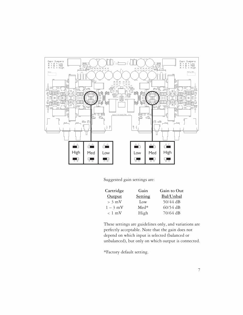
Suggested gain settings are:
Cartridge Gain Gain to OutOutput Setting Bal/Unbal> 3 mV Low 50/44 dB
1 – 3 mV Med* 60/54 dB< 1 mV High 70/64 dB
These settings are guidelines only, and variations areperfectly acceptable. Note that the gain does notdepend on which input is selected (balanced orunbalanced), but only on which output is connected.
*Factory default setting.
7
Setting the Loading
Cartridge loading can be adjusted with switches onthe rear panel. The loading options built in to theAyre P-5xe are 47 kΩ, 1000 Ω, and 100 Ω. There isa bank of two switches for each channel. When bothswitches are in the “Up” position the cartridge loadis 47 kΩ, which is suitable for almost all cartridges.
It is recommended that theloading not be changed from
47 k when using amoving-magnet cartridge.
Some moving-coil cartridges will yield better sonicperformance if they are loaded with a lowerimpedance. Usually, a lower load impedance resultsin a more focused soundstage, with greater imagesolidity and less apparent distortion. A higher loadimpedance will give a more open sound, withgreater air and life. The final loading value must bechosen by ear to give the best sound in yourparticular system.
Break-In
100 to 500 hours of musicplayed through the system will
ensure full break-in.
Due to the manufacturing processes used for thecircuit board and capacitors, a break-in period isnecessary for the phono preamplifier to reach its fullperformance potential.
8
Optimization and
Customization
Technically oriented users may wish to exploreadditional customization options that are available.
Custom Loading Resistors
When using custom loadingresistors, leave the loading
switches in the “Up” position(47 kΩ).
Should additional loading values be desired, customloading resistors are also easily accommodated. Asthere are two types of inputs (balanced andunbalanced), simply connect the desired value ofloading resistor to the unused inputs using anappropriate connector (RCA or XLR).
Required materials include a pair of high-qualityresistors of the desired value and an additional pairof the appropriate connectors (RCA or XLR). Malepolarity connectors are required for the customloading resistors.
When using a balanced (XLR) connection to theturntable, solder the desired value loading resistorsbetween the center pin and the shell of theadditional male RCA connectors. These additionalconnectors are then inserted into the otherwiseunused unbalanced inputs of the P-5xe.
9
When using an unbalanced (RCA) connection to theturntable, solder the custom loading resistorsbetween pins 2 and 3 of the additional male XLRconnectors. These additional connectors are theninserted into the otherwise unused balanced inputsof the P-5xe.
Custom Phono Cables
As noted in the “Connections and Installation”section, a balanced connection from turntable tophono preamplifier will provide the highest level ofperformance. While Ayre offers pre-made cables ofthe correct configuration, some users will prefer tohave custom phono cables made by anothermanufacturer, or to modify their existing cables.This section gives details on how to achieve theproper connection.
In general, there will be a total of five connections tothe turntable:
• Left positive• Left negative• Right positive• Right negative• Tonearm and/or turntable ground
These should be connected to the phonopreamplifier using only a single ground connection,in order to eliminate hum-inducing ground loops.
10

Turntables with RCA Connectors
One common turntable configuration has two RCAjacks plus a ground post. Following is a schematicdiagram of a suitable custom cable:
This configuration has two separate cables plus aground wire, and requires balanced cabling with atleast two conductors plus a shield. If the cabling hasa third conductor (in addition to the shield), itshould be connected to pin 1 of the XLR connectorand left unconnected at the RCA end. If the cablinghas four or more conductors, they should beparalleled to create two composite conductors.
Normally this turntable configuration has the RCAconnectors mounted to an unsuspended part of theturntable and the cable’s stiffness will not interferewith the turntable’s suspension. Should the RCAconnectors be mounted to a suspended part of the
11
1
1
Male RCA Shield Male XLR
ToTurntable
To PhonoPreamplifier
Ground WireSpade Lug Spade Lug
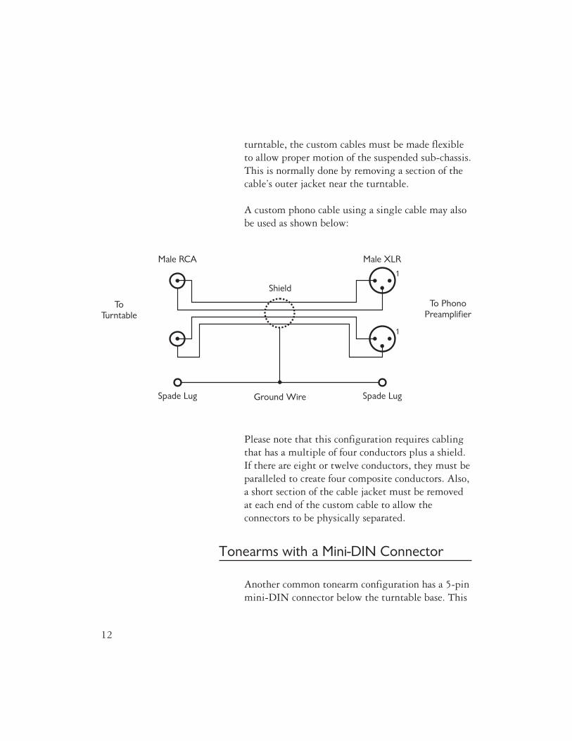
turntable, the custom cables must be made flexibleto allow proper motion of the suspended sub-chassis.This is normally done by removing a section of thecable’s outer jacket near the turntable.
A custom phono cable using a single cable may alsobe used as shown below:
Please note that this configuration requires cablingthat has a multiple of four conductors plus a shield.If there are eight or twelve conductors, they must beparalleled to create four composite conductors. Also,a short section of the cable jacket must be removedat each end of the custom cable to allow theconnectors to be physically separated.
Tonearms with a Mini-DIN Connector
Another common tonearm configuration has a 5-pinmini-DIN connector below the turntable base. This
12
1
1
Shield
Male XLR
ToTurntable
To PhonoPreamplifier
Ground Wire Spade LugSpade Lug
Male RCA
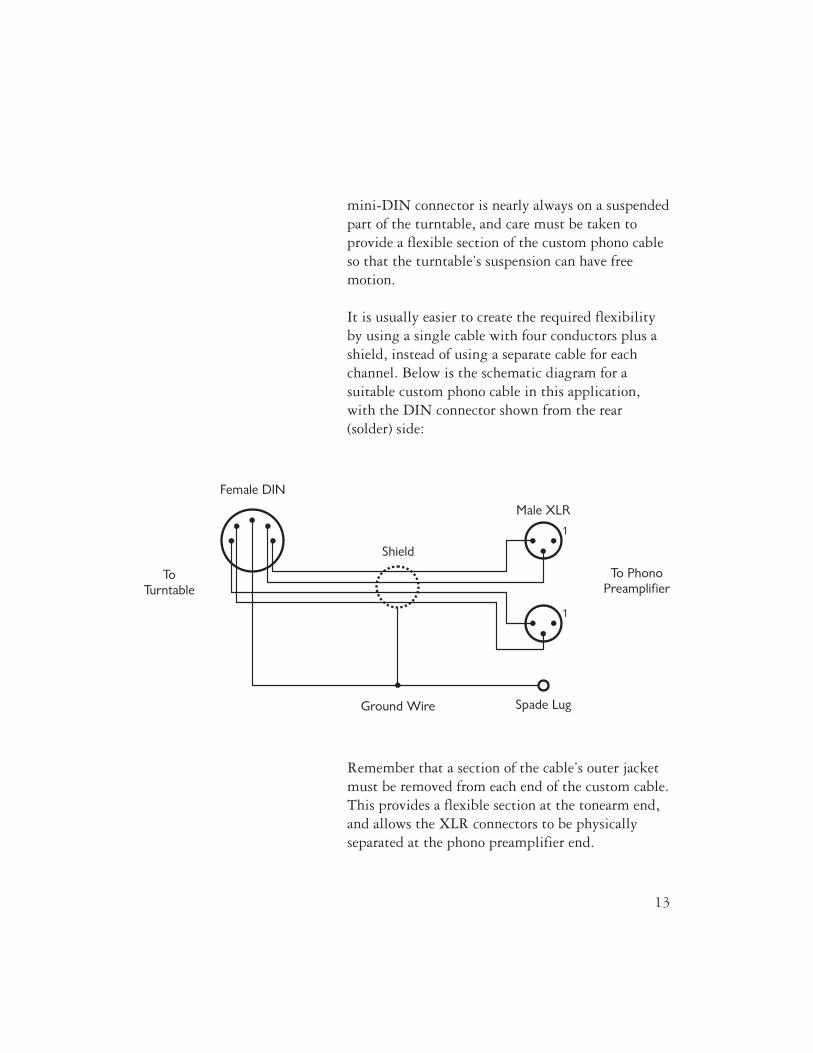
mini-DIN connector is nearly always on a suspendedpart of the turntable, and care must be taken toprovide a flexible section of the custom phono cableso that the turntable’s suspension can have freemotion.
It is usually easier to create the required flexibilityby using a single cable with four conductors plus ashield, instead of using a separate cable for eachchannel. Below is the schematic diagram for asuitable custom phono cable in this application,with the DIN connector shown from the rear(solder) side:
Remember that a section of the cable’s outer jacketmust be removed from each end of the custom cable.This provides a flexible section at the tonearm end,and allows the XLR connectors to be physicallyseparated at the phono preamplifier end.
13
ToTurntable
To PhonoPreamplifier
Female DIN
1
1
Shield
Male XLR
Ground Wire Spade Lug

In the event that a four conductor cable is notavailable, a pair of cables with at least twoconductors each may be used as shown in thefollowing diagram, with the DIN connector shownfrom the rear (solder) side:
In this situation extra care must be taken to providea flexible section to avoid interference with theturntable’s suspension. If the cabling has threeconductors (in addition to the shield), the thirdconductor should be connected to pin 1 of the XLRconnectors and left unconnected at the tonearm end.
14
1
1
Shield Male XLR
ToTurntable
To PhonoPreamplifier
Ground Wire Spade Lug
Female DIN
Numbers and
Specifications
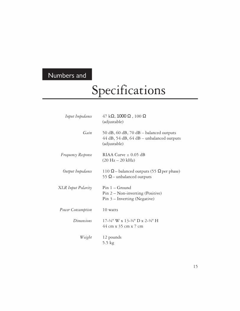
Input Impedance 47 kΩ, 1000 Ω, 100 Ω(adjustable)
Gain 50 dB, 60 dB, 70 dB – balanced outputs44 dB, 54 dB, 64 dB – unbalanced outputs(adjustable)
Frequency Response RIAA Curve ± 0.05 dB(20 Hz – 20 kHz)
Output Impedance 110 Ω– balanced outputs (55 Ωper phase)55 Ω– unbalanced outputs
XLR Input Polarity Pin 1 – GroundPin 2 – Non-inverting (Positive)Pin 3 – Inverting (Negative)
Power Consumption 10 watts
Dimensions 17-¼" W x 13-¾" D x 2-¾" H44 cm x 35 cm x 7 cm
Weight 12 pounds5.5 kg
15

Statement of
Warranty
North American Warranty
Your Ayre P-5xe phono preamplifier is warrantedagainst defects in workmanship and materials for aperiod of ninety days from the date of originalpurchase. This ninety-day coverage is automaticupon acceptance of delivery and no registration isrequired.
Additionally you have the option, at no cost, toextend the warranty for a period of five years fromthe date of purchase by returning the completedWarranty Registration Card and a photocopy ofyour original purchase receipt in the enclosedpostage-paid envelope to Ayre within thirty days ofproduct delivery. This optional warranty is onlyavailable within the thirty-day registration period.
16
North American Warranty Statement
1. If any defects are found in the materials orworkmanship of this Ayre product within thewarranty period, the unit will be repaired orreplaced by Ayre Acoustics, Inc. (Ayre) or itsauthorized agent.
2. Purchaser must return the product, packed in theoriginal shipping carton, freight prepaid to:
Ayre Acoustics, Inc.2300-B Central AvenueBoulder, Colorado 80301
or to Ayre’s authorized agent. The product must beaccompanied by a written description of the defectand a photocopy of your original purchase receipt.Ayre will not be responsible for any shippingdamage and strongly recommends the purchase ofshipping insurance.
3. Ayre reserves the right to inspect any productthat is the subject of any warranty claim prior torepairing or replacing it. Final determination ofwarranty coverage lies solely with Ayre.
Out-of-warranty claims will be billed for labor,materials, return freight, and insurance as required.Any product for which a warranty claim is acceptedwill be returned to the purchaser and the cost ofshipping and insurance will be factory prepaidwithin the boundaries of the USA. Units to beshipped outside of the USA will be shipped freightcollect only.
17

4. Ayre strives to manufacture the finest possibleequipment, and therefore reserves the right to makeimprovements on its products, without necessarilyassuming any obligation to retrofit such changesupon its previously manufactured models.
5. The above warranty is the sole warranty given byAyre, and is in lieu of all other warranties. Allimplied warranties, including warranties ofmerchantability or fitness for any particular purposeshall be strictly limited to the duration of the abovewarranty. Ayre shall have no further obligation ofany kind, whether express or implied. Further, Ayreshall in no event be obligated for any incidental orconsequential damages as a result of any defect orany warranty claim, whether express or implied.
6. Ayre does not authorize any third party,including any dealer or sales representative, toassume any liability of Ayre or make any warrantyfor Ayre. The unit must not have been altered orimproperly serviced. The serial number on the unitmust not have been altered or removed.
7. The remaining period of this warranty is onlytransferable to subsequent purchasers if the productis resold by an authorized Ayre dealer.
International Warranty
Warranty terms outside of North America may vary.Please contact the authorized Ayre distributor inyour country of purchase for the terms of warrantyand also the service itself.
18
A Place for
Notes
Serial Number:
Purchase Date:
Dealer:
Salesperson:
________________________________________
________________________________________
________________________________________
________________________________________
19

20 Revision 1.1


Ayre Acoustics, Inc.2300-B Central Avenue
Boulder, Colorado 80301
www.ayre.com+1-303-442-7300