awareness of marking permanency and black top … of marking permanency and ... phillip zulueta,...
TRANSCRIPT
Awareness of Marking Permanency and Black Top Testing in Today’s Electronic Component Industry
November 2012
Presented to SAE INTERNATIONAL G-19
Counterfeit Electronic Parts Committee
Attn: Phillip Zulueta, Chairman
Presented By: Joseph Federico, Director of Operations
New Jersey Micro Electronics Testing Inc.
Awareness of Marking Permanency and Black Top Testing in Today’s Electronic Component Industry
November 2012 Page 2
Awareness of Marking Permanency and Black Top Testing in Today’s Electronic Component Industry
November 2012 Page 3
Contents Background ................................................................................................................................................... 4
Issue: One testing approach does not fit all components ...................................................................... 4
Counterfeiting – A Worldwide Dilemma ................................................................................................... 4
Suspect marking after testing ................................................................................................................... 4
Marking Permanency/Blacktop Testing Today ............................................................................................. 5
EXEMPLAR: The Case of a Known Good Component Failing Dynasolve Testing ..................................... 5
Conclusion ..................................................................................................................................................... 7
Appendix ....................................................................................................................................................... 8
Appendix 1: Resistance to Solvents – Microcircuits (Ceramic Devices) .................................................. 8
MIL-STD-883H ....................................................................................................................................... 8
METHOD 2015.13 .................................................................................................................................. 8
RESISTANCE TO SOLVENTS .................................................................................................................... 8
MIL-STD-750E ...................................................................................................................................... 14
Appendix 2: Testing for Plastic Parts: Marking Permanency (Resistance to Solvents) ........................... 17
Test 1 (Mineral Spirits) ........................................................................................................................ 17
Test 2 (Acetone Test) .......................................................................................................................... 19
Test 3 (1-Methyl 2-Pyrrolidone Test) .................................................................................................. 20
Test 4 (Dynasolve 711/750) ................................................................................................................ 22
Appendix 3: Original Certificate of Conformance ................................................................................ 24
Awareness of Marking Permanency and Black Top Testing in Today’s Electronic Component Industry
November 2012 Page 4
Background
Issue: One testing approach does not fit all components Over the past few years new techniques of black top marking tests have been implemented to discover
non authentic marking and coating processes on electronic component devices. These tests can be
highly effective at discovering counterfeit plastic components. However, the same tests can result in
false positives when used on ceramic packages that have not been blacktopped/coated or on can
package devices. We suggest that resistance to solvents testing be performed on these devices in
accordance with MIL-STD 750 and MIL-STD 883 to evaluate the device’s marking permanency testing.
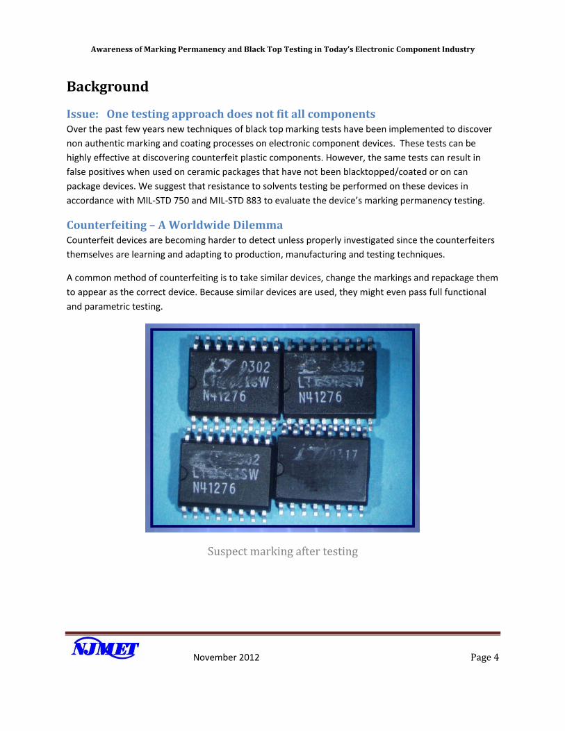
Counterfeiting – A Worldwide Dilemma Counterfeit devices are becoming harder to detect unless properly investigated since the counterfeiters
themselves are learning and adapting to production, manufacturing and testing techniques.
A common method of counterfeiting is to take similar devices, change the markings and repackage them
to appear as the correct device. Because similar devices are used, they might even pass full functional
and parametric testing.
Suspect marking after testing
Awareness of Marking Permanency and Black Top Testing in Today’s Electronic Component Industry
November 2012 Page 5
Marking Permanency/Blacktop Testing Today
Marking permanency testing can reveal many re-marks, black topping, sanding, etc.
Mineral Spirits Testing, Acetone Testing, 1- Methyl 2- Pyrrolidone Testing and Dynasolve Testing
have been vital in uncovering many anomalies associated with counterfeit marked units on
plastic packages that have been blacktopped.
The above tests are now commonly used for testing all components, including those made of
plastic, ceramic (non-blacktopped) and canned package components.
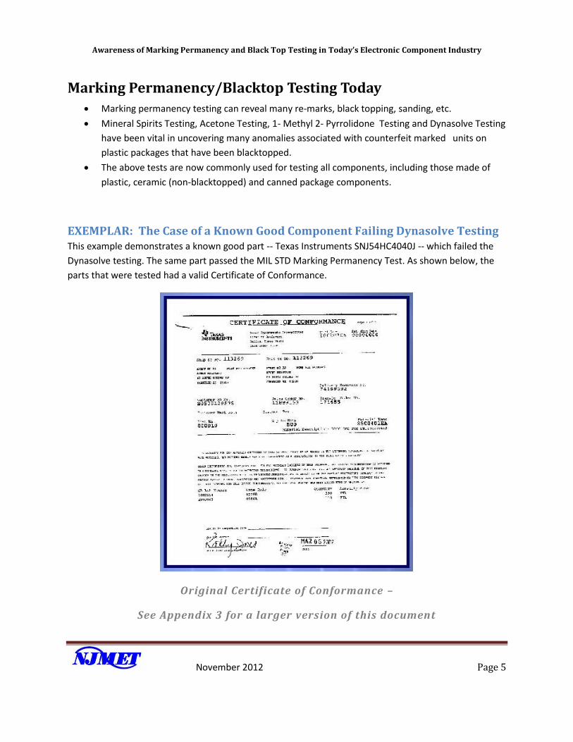
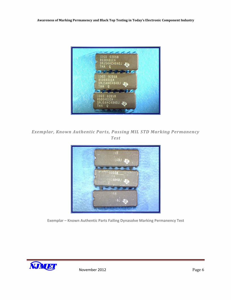
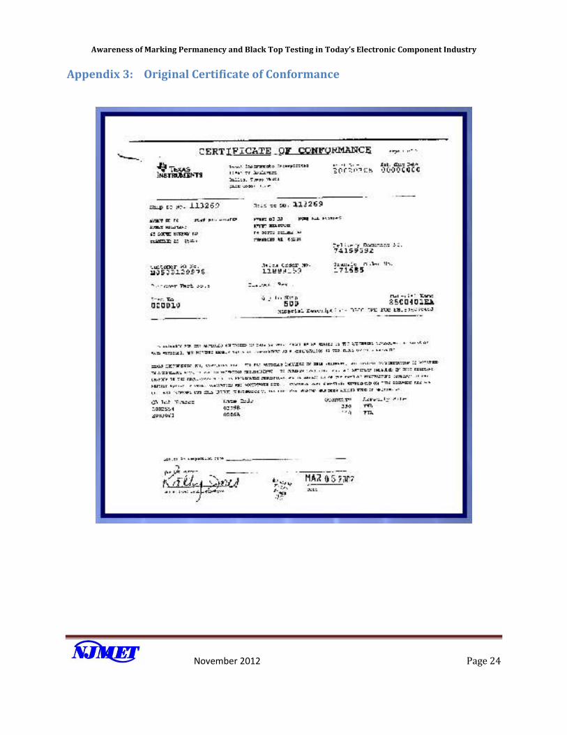
EXEMPLAR: The Case of a Known Good Component Failing Dynasolve Testing This example demonstrates a known good part -- Texas Instruments SNJ54HC4040J -- which failed the
Dynasolve testing. The same part passed the MIL STD Marking Permanency Test. As shown below, the
parts that were tested had a valid Certificate of Conformance.
Original Certificate of Conformance –
See Appendix 3 for a larger version of this document
Awareness of Marking Permanency and Black Top Testing in Today’s Electronic Component Industry
November 2012 Page 6
Exemplar, Known Authentic Parts, Passing MIL STD Marking Permanency
Test
Exemplar – Known Authentic Parts Failing Dynasolve Marking Permanency Test
Awareness of Marking Permanency and Black Top Testing in Today’s Electronic Component Industry
November 2012 Page 7
Conclusion While Mineral Spirits testing, Acetone testing, 1- Methyl 2- Pyrrolidone testing and Dynasolve testing
have been vital in uncovering many anomalies associated with counterfeit marked units on plastic and
ceramic parts that have been black topped. We have shown that using the very same four step
processes can, in fact, reject a known authentic ceramic (hermetically sealed) unit that has not been
black topped.
We recommend that any hermetically sealed (Ceramic or Can Package) device not showing any evidence
of Black Top Marking should undergo a Resistance to Solvent Test in accordance with its respective MIL-
STANDARD to evaluate Marking Permanency and not rely on the blacktop marking resistance to solvents
tests.
Awareness of Marking Permanency and Black Top Testing in Today’s Electronic Component Industry
November 2012 Page 8
Appendix
Appendix 1: Resistance to Solvents – Microcircuits (Ceramic Devices)
MIL-STD-883H
METHOD 2015.13
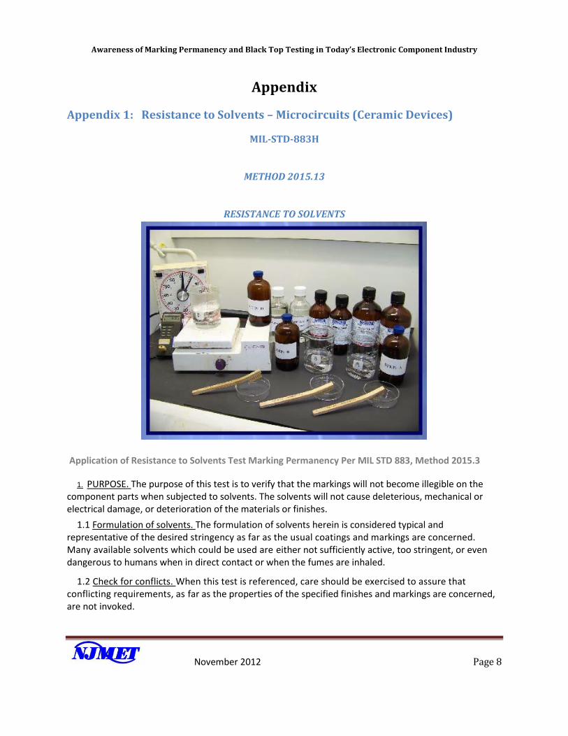
RESISTANCE TO SOLVENTS
Application of Resistance to Solvents Test Marking Permanency Per MIL STD 883, Method 2015.3
1. PURPOSE. The purpose of this test is to verify that the markings will not become illegible on the component parts when subjected to solvents. The solvents will not cause deleterious, mechanical or electrical damage, or deterioration of the materials or finishes.
1.1 Formulation of solvents. The formulation of solvents herein is considered typical and representative of the desired stringency as far as the usual coatings and markings are concerned. Many available solvents which could be used are either not sufficiently active, too stringent, or even dangerous to humans when in direct contact or when the fumes are inhaled.
1.2 Check for conflicts. When this test is referenced, care should be exercised to assure that conflicting requirements, as far as the properties of the specified finishes and markings are concerned, are not invoked.
Awareness of Marking Permanency and Black Top Testing in Today’s Electronic Component Industry
November 2012 Page 9
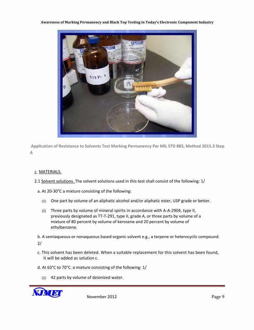
Application of Resistance to Solvents Test Marking Permanency Per MIL STD 883, Method 2015.3 Step
A
2. MATERIALS.
2.1 Solvent solutions. The solvent solutions used in this test shall consist of the following: 1/
a. At 20-30°C a mixture consisting of the following:
(1) One part by volume of an aliphatic alcohol and/or aliphatic ester, USP grade or better.
(2) Three parts by volume of mineral spirits in accordance with A-A-2904, type II, previously designated as TT-T-291, type II, grade A, or three parts by volume of a mixture of 80 percent by volume of kerosene and 20 percent by volume of ethylbenzene.
b. A semiaqueous or nonaqueous based organic solvent e.g., a terpene or heterocyclic compound.
2/
c. This solvent has been deleted. When a suitable replacement for this solvent has been found, it will be added as solution c.
d. At 63°C to 70°C. a mixture consisting of the following: 1/
(1) 42 parts by volume of deionized water.
Awareness of Marking Permanency and Black Top Testing in Today’s Electronic Component Industry
November 2012 Page 10
(2) 1 part by volume of propylene glycol monomethyl ether.
(3) 1 part by volume of monoethanolamine or equivalent inorganic base to achieve the same pH.
2.1.1 Solvent solutions, safety aspects. Solvent solutions listed in a through d above exhibit some potential for health and safety hazards. The following safety precautions should be observed:
a. Avoid contact with eyes.
b. Avoid prolonged contact with skin.
c. Provide adequate ventilation.
d. Avoid open flame.
e. Avoid contact with very hot surfaces.
1/ Normal safety precautions for handling these solutions (e.g., same as those for diluted ammonium hydroxide) based on O.S.H.A rules for Monoethanolamine or other precautionary measures with regard to flash point, toxicity, etc.
2/ Or any EPA demonstrated equivalent. When using EPA approved alternative solutions for test, the device manufacturer should consider the recommended temperature for cleaning specified by the solvent supplier.
2.2 Vessel. The vessel shall be a container made of inert material, and of sufficient size to permit complete immersion of the specimens in the solvent solutions specified in 2.1.
2.3 Brush. The brush shall be a toothbrush with a handle made of a nonreactive material. The brush shall have at least three long rows of hard (or firm) bristles, the free ends of which shall lie substantially in the same plane. The toothbrush shall be used exclusively with a single solvent and when there is any evidence of softening, bending, wear, or loss of bristles, it shall be discarded.
Awareness of Marking Permanency and Black Top Testing in Today’s Electronic Component Industry
November 2012 Page 11
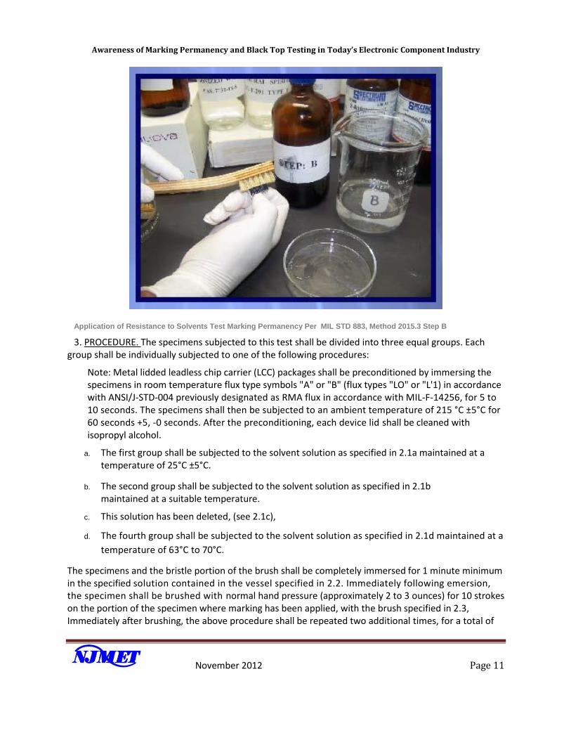
Application of Resistance to Solvents Test Marking Permanency Per MIL STD 883, Method 2015.3 Step B
3. PROCEDURE. The specimens subjected to this test shall be divided into three equal groups. Each group shall be individually subjected to one of the following procedures:
Note: Metal lidded leadless chip carrier (LCC) packages shall be preconditioned by immersing the specimens in room temperature flux type symbols "A" or "B" (flux types "LO" or "L'1) in accordance with ANSI/J-STD-004 previously designated as RMA flux in accordance with MIL-F-14256, for 5 to 10 seconds. The specimens shall then be subjected to an ambient temperature of 215 °C ±5°C for 60 seconds +5, -0 seconds. After the preconditioning, each device lid shall be cleaned with isopropyl alcohol.
a. The first group shall be subjected to the solvent solution as specified in 2.1a maintained at a temperature of 25°C ±5°C.
b. The second group shall be subjected to the solvent solution as specified in 2.1b maintained at a suitable temperature.
c. This solution has been deleted, (see 2.1c),
d. The fourth group shall be subjected to the solvent solution as specified in 2.1d maintained at a
temperature of 63°C to 70°C.
The specimens and the bristle portion of the brush shall be completely immersed for 1 minute minimum in the specified solution contained in the vessel specified in 2.2. Immediately following emersion, the specimen shall be brushed with normal hand pressure (approximately 2 to 3 ounces) for 10 strokes on the portion of the specimen where marking has been applied, with the brush specified in 2.3, Immediately after brushing, the above procedure shall be repeated two additional times, for a total of
Awareness of Marking Permanency and Black Top Testing in Today’s Electronic Component Industry
November 2012 Page 12
three immersions followed by brushings. The brush stroke shall be directed in a forward direction, across the surface of the specimen being tested. After completion of the third immersion and brushing, devices shall be rinsed and all surfaces air blown dry. After 5 minutes, the specimens shall be examined to determine the extent, if any, of deterioration that was incurred.
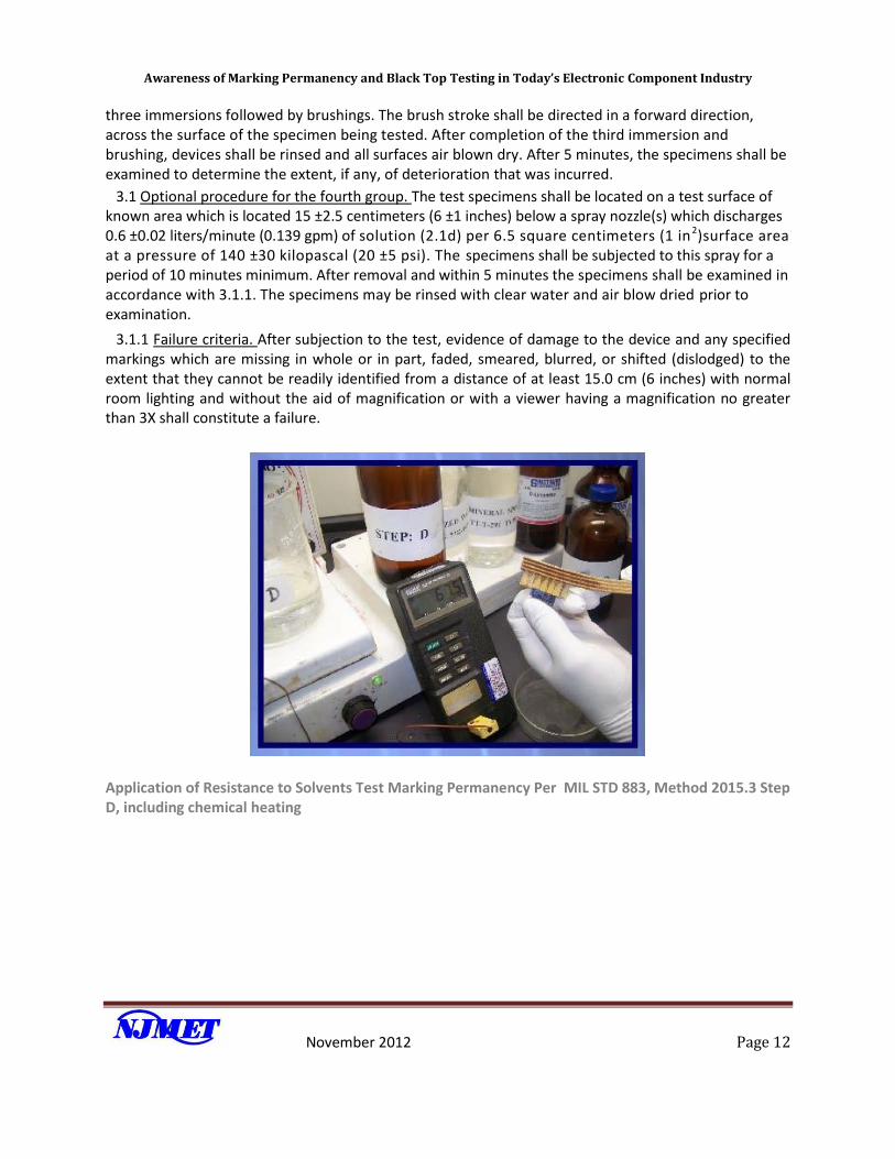
3.1 Optional procedure for the fourth group. The test specimens shall be located on a test surface of known area which is located 15 ±2.5 centimeters (6 ±1 inches) below a spray nozzle(s) which discharges 0.6 ±0.02 liters/minute (0.139 gpm) of solution (2.1d) per 6.5 square centimeters (1 in2)surface area at a pressure of 140 ±30 kilopascal (20 ±5 psi). The specimens shall be subjected to this spray for a period of 10 minutes minimum. After removal and within 5 minutes the specimens shall be examined in accordance with 3.1.1. The specimens may be rinsed with clear water and air blow dried prior to examination.
3.1.1 Failure criteria. After subjection to the test, evidence of damage to the device and any specified markings which are missing in whole or in part, faded, smeared, blurred, or shifted (dislodged) to the extent that they cannot be readily identified from a distance of at least 15.0 cm (6 inches) with normal room lighting and without the aid of magnification or with a viewer having a magnification no greater than 3X shall constitute a failure.
Application of Resistance to Solvents Test Marking Permanency Per MIL STD 883, Method 2015.3 Step D, including chemical heating
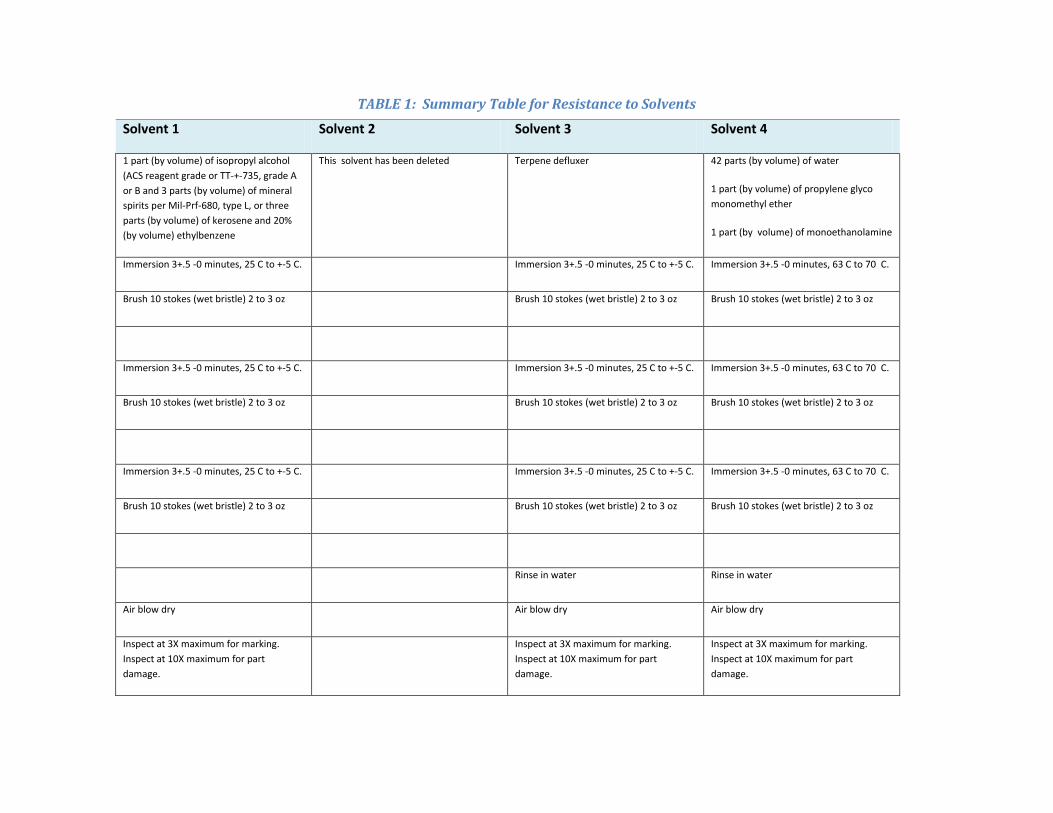
TABLE 1: Summary Table for Resistance to Solvents
Solvent 1 Solvent 2 Solvent 3 Solvent 4
1 part (by volume) of isopropyl alcohol
(ACS reagent grade or TT-+-735, grade A
or B and 3 parts (by volume) of mineral
spirits per Mil-Prf-680, type L, or three
parts (by volume) of kerosene and 20%
(by volume) ethylbenzene
This solvent has been deleted Terpene defluxer 42 parts (by volume) of water
1 part (by volume) of propylene glyco
monomethyl ether
1 part (by volume) of monoethanolamine
Immersion 3+.5 -0 minutes, 25 C to +-5 C. Immersion 3+.5 -0 minutes, 25 C to +-5 C. Immersion 3+.5 -0 minutes, 63 C to 70 C.
Brush 10 stokes (wet bristle) 2 to 3 oz Brush 10 stokes (wet bristle) 2 to 3 oz Brush 10 stokes (wet bristle) 2 to 3 oz
Immersion 3+.5 -0 minutes, 25 C to +-5 C. Immersion 3+.5 -0 minutes, 25 C to +-5 C. Immersion 3+.5 -0 minutes, 63 C to 70 C.
Brush 10 stokes (wet bristle) 2 to 3 oz Brush 10 stokes (wet bristle) 2 to 3 oz Brush 10 stokes (wet bristle) 2 to 3 oz
Immersion 3+.5 -0 minutes, 25 C to +-5 C. Immersion 3+.5 -0 minutes, 25 C to +-5 C. Immersion 3+.5 -0 minutes, 63 C to 70 C.
Brush 10 stokes (wet bristle) 2 to 3 oz Brush 10 stokes (wet bristle) 2 to 3 oz Brush 10 stokes (wet bristle) 2 to 3 oz
Rinse in water Rinse in water
Air blow dry Air blow dry Air blow dry
Inspect at 3X maximum for marking.
Inspect at 10X maximum for part
damage.
Inspect at 3X maximum for marking.
Inspect at 10X maximum for part
damage.
Inspect at 3X maximum for marking.
Inspect at 10X maximum for part
damage.
Awareness of Marking Permanency and Black Top Testing in Today’s Electronic Component Industry
November 2012 Page 14
MIL-STD-750E
METHOD 1022.5 Semiconductors (Can packages)
RESISTANCE TO SOLVENTS
1. Purpose. The purpose of this test is to verify that the markings will not become illegible on the component parts when subjected to solvents. The solvents will not cause deleterious, mechanical or electrical damage, or deterioration of the materials or finishes.
1.1 Formulation of solvents. The formulation of solvents herein is considered typical and representative of the desired stringency as far as the usual coatings and markings are concerned. Many available solvents which could be used are either not sufficiently active, too stringent, or even dangerous to humans when in direct contact or when the fumes are inhaled.
1.2 Check for conflicts. When this test is referenced, care should be exercised to assure that conflicting requirements, as far as the properties of the specified finishes and markings are concerned, are not invoked.
2. Materials.
2.1 Solvent solutions. The solvent solutions used in this test shall consist of the following:
a. A mixture consisting of the following:
(1) One part by volume of isopropyl alcohol, AC.S. (American Chemical Society) Reagent Grade, or isopropyl alcohol in accordance with TT-I-735, grade A or B-
(2) Three parts by volume of mineral spirits in accordance with MIL-PRF-680, type II, grade A, or three parts by volume of a mixture of 80 percent by volume of kerosene and 20 percent by volume ethylbenzene.
b. A semiaqueous based solvent (defluxer (e.g., a turpene)) consisting of a minimum of 60 percent Limonene and a surfactant heated to +32°C ±5°C. 1/
c. At +63°C to +70°C, a mixture consisting of the following: 2/
(1) 42 parts by volume of deionized water.
(2) 1 part by volume of propylene glycol monomethyl ether.
(3) 1 part by volume of monoethanolamine.
2.1.1 Solvent solutions, safety aspects. Solvent solutions listed in 2.1 herein exhibit some potential for health and safety hazards. The following safety precautions should be observed:
a. Avoid contact with eyes.
Awareness of Marking Permanency and Black Top Testing in Today’s Electronic Component Industry
November 2012 Page 15
b. Avoid prolonged contact with skin.
c. Provide adequate ventilation.
d. Avoid open flame.
e. Avoid contact with very hot surfaces.
1/ Or any equivalent Environmental Protection Agency (EPA) approved Hydrochlorofluorocarbons (HCFC) or terpene solvent or demonstrated equivalent.
2/ Normal safety precaution for handling this solution (e.g., same as those for diluted ammonium hydroxide) based on Occupational Safety and Health Administration (O.S.H.A.) rules for monoethanolamine.
2.2 Vessel. The vessel shall be a container made of inert material, and of sufficient size to permit complete immersion of the specimens in the solvent solutions specified in 2.1.
2.3 Brush. The brush shall be a brush with a handle made of a nonreactive material. The brush shall have three long rows of hard bristles, the free ends of which shall lie substantially in the same plane. The brush shall be used exclusively with a single solvent and when there is any evidence of softening, bending, wear, or loss of bristles, it shall be discarded.
3. Procedure. The specimens subjected to this test shall be divided into three groups. Metal lidded leadless chip carrier (LCC) packages shall be preconditioned by immersing the specimens in room temperature ROL1 flux (in accordance with J-STD-004A, Requirements for Soldering Fluxes) for 5 to 10 seconds. The specimens shall then be subjected to an ambient temperature of +215°C ±5°C for 60 seconds +5, -0 seconds. After the preconditioning, each device lid shall be cleaned with isopropyl alcohol. Each group shall be individually subjected to one of the following procedures:
a. The first group shall be subjected to the solvent solution as specified in 2.1.a. maintained at a temperature of +25°C ±5°C.
b. The second group shall be subjected to the solvent solution as specified in 2.1.b. maintained at a temperature of +32°C ±5°C.
c. The third group shall be subjected to the solvent solution as specified in 2.1.c. maintained at a temperature of +63°C to +70°C.
The specimens and the bristle portion of the brush shall be completely immersed for 1 minute minimum in the specified solution contained in the vessel specified in 2.2. Immediately following immersion, the specimen shall be brushed with normal hand pressure (approximately 2 to 3 ounces) for ten strokes on the portion of the specimen where marking has been applied, with the brush specified in 2.3. Immediately after brushing, the above procedure shall be repeated two additional times, for a total of three immersions followed by brushings. The brush stroke shall be directed in a forward direction, across the surface of the specimen being tested. After completion of the third immersion and brushing, devices shall be rinsed and all surfaces air blown dry. After 5
Awareness of Marking Permanency and Black Top Testing in Today’s Electronic Component Industry
November 2012 Page 16
minutes, the specimens shall be examined to determine the extent, if any, of deterioration that was incurred.
3.1 Optional procedure for the third group. The test specimens shall be located on a test surface of known area which is located 6 ±1 inches (15.24 ±2.54 centimeters) below a spray nozzle(s) which discharges 0.139 gpm
(0.6 ±.0.02 liters) minute) of solution (see 2.1.c) 1 in2 (6.5 square centimeters) of surface area at a pressure of 20 ±5 psi (137.90 ±34.41 kilopascal). The specimens shall be subjected to this spray for a period of 10 minutes minimum. Within five minutes after removal of the specimens, they shall be examined in accordance with 3.1.1. The specimens may be rinsed with clear water and air blown dried prior to examination.
3.1.1 Failure criteria. After subject to the test, evidence of damage to the device and any specified markings which are missing in whole or in part, faded, smeared, blurred, or shifted (dislodged) to the extent that they cannot be readily identified from a distance of at least 6 inches (15.24 cm) with normal room lighting, and without the aid of magnification, or with a viewer having a magnification no greater than 3X, shall constitute a failure,
Awareness of Marking Permanency and Black Top Testing in Today’s Electronic Component Industry
November 2012 Page 17
Appendix 2: Testing for Plastic Parts: Marking Permanency (Resistance to
Solvents)
PURPOSE:
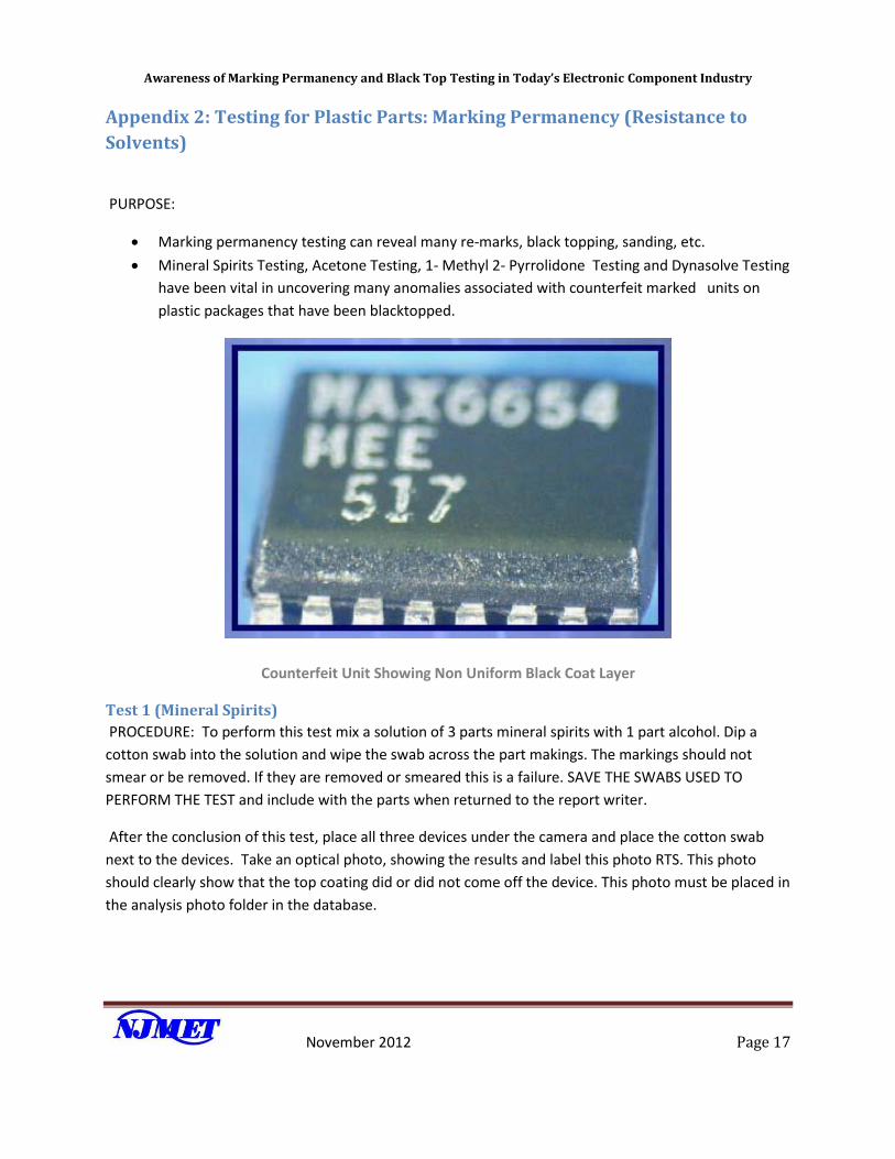
Marking permanency testing can reveal many re-marks, black topping, sanding, etc.
Mineral Spirits Testing, Acetone Testing, 1- Methyl 2- Pyrrolidone Testing and Dynasolve Testing
have been vital in uncovering many anomalies associated with counterfeit marked units on
plastic packages that have been blacktopped.
Counterfeit Unit Showing Non Uniform Black Coat Layer
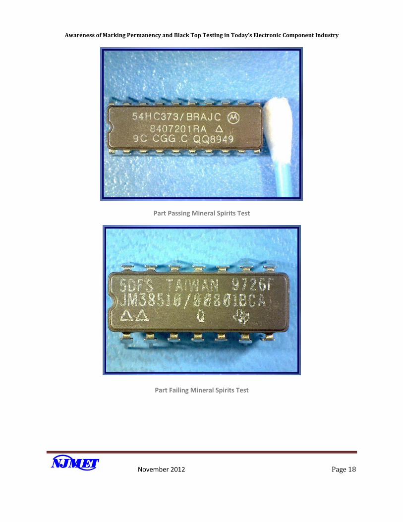
Test 1 (Mineral Spirits)
PROCEDURE: To perform this test mix a solution of 3 parts mineral spirits with 1 part alcohol. Dip a
cotton swab into the solution and wipe the swab across the part makings. The markings should not
smear or be removed. If they are removed or smeared this is a failure. SAVE THE SWABS USED TO
PERFORM THE TEST and include with the parts when returned to the report writer.
After the conclusion of this test, place all three devices under the camera and place the cotton swab
next to the devices. Take an optical photo, showing the results and label this photo RTS. This photo
should clearly show that the top coating did or did not come off the device. This photo must be placed in
the analysis photo folder in the database.
Awareness of Marking Permanency and Black Top Testing in Today’s Electronic Component Industry
November 2012 Page 18
Part Passing Mineral Spirits Test
Part Failing Mineral Spirits Test
Awareness of Marking Permanency and Black Top Testing in Today’s Electronic Component Industry
November 2012 Page 19
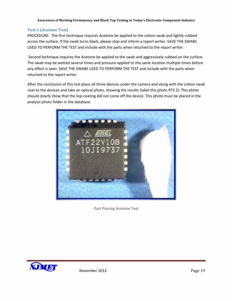
Test 2 (Acetone Test)
PROCEDURE: The first technique requires Acetone be applied to the cotton swab and lightly rubbed
across the surface. If the swab turns black, please stop and inform a report writer. SAVE THE SWABS
USED TO PERFORM THE TEST and include with the parts when returned to the report writer.
Second technique requires the Acetone be applied to the swab and aggressively rubbed on the surface.
The swab may be wetted several times and pressure applied to the same location multiple times before
any effect is seen. SAVE THE SWABS USED TO PERFORM THE TEST and include with the parts when
returned to the report writer.
After the conclusion of this test place all three devices under the camera and along with the cotton swab
next to the devices and take an optical photo, showing the results (label this photo RTS 2). This photo
should clearly show that the top-coating did not come off the device. This photo must be placed in the
analysis photo folder in the database.
Part Passing Acetone Test
Awareness of Marking Permanency and Black Top Testing in Today’s Electronic Component Industry
November 2012 Page 20
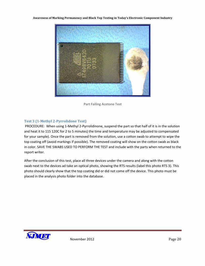
Part Failing Acetone Test
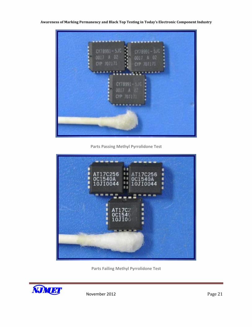
Test 3 (1-Methyl 2-Pyrrolidone Test)
PROCEDURE: When using 1-Methyl 2-Pyrrolidinone, suspend the part so that half of it is in the solution
and heat it to 115 120C for 2 to 5 minutes) the time and temperature may be adjusted to compensated
for your sample). Once the part is removed from the solution, use a cotton swab to attempt to wipe the
top coating off (avoid markings if possible). The removed coating will show on the cotton swab as black
in color. SAVE THE SWABS USED TO PERFORM THE TEST and include with the parts when returned to the
report writer.
After the conclusion of this test, place all three devices under the camera and along with the cotton
swab next to the devices ad take an optical photo, showing the RTS results (label this photo RTS 3). This
photo should clearly show that the top coating did or did not come off the device. This photo must be
placed in the analysis photo folder into the database.
Awareness of Marking Permanency and Black Top Testing in Today’s Electronic Component Industry
November 2012 Page 21
Parts Passing Methyl Pyrrolidone Test
Parts Failing Methyl Pyrrolidone Test
Awareness of Marking Permanency and Black Top Testing in Today’s Electronic Component Industry
November 2012 Page 22
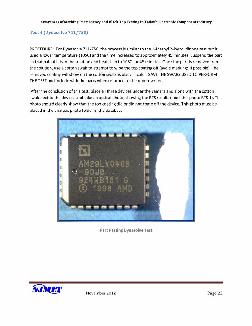
Test 4 (Dynasolve 711/750)
PROCEDURE: For Dynasolve 711/750, the process is similar to the 1-Methyl 2-Pyrrolidinone test but it
used a lower temperature (105C) and the time increased to approximately 45 minutes. Suspend the part
so that half of it is in the solution and heat it up to 105C for 45 minutes. Once the part is removed from
the solution, use a cotton swab to attempt to wipe the top coating off (avoid markings if possible). The
removed coating will show on the cotton swab as black in color. SAVE THE SWABS USED TO PERFORM
THE TEST and include with the parts when returned to the report writer.
After the conclusion of this test, place all three devices under the camera and along with the cotton
swab next to the devices and take an optical photo, showing the RTS results (label this photo RTS 4). This
photo should clearly show that the top coating did or did not come off the device. This photo must be
placed in the analysis photo folder in the database.
Part Passing Dynasolve Test
Awareness of Marking Permanency and Black Top Testing in Today’s Electronic Component Industry
November 2012 Page 23
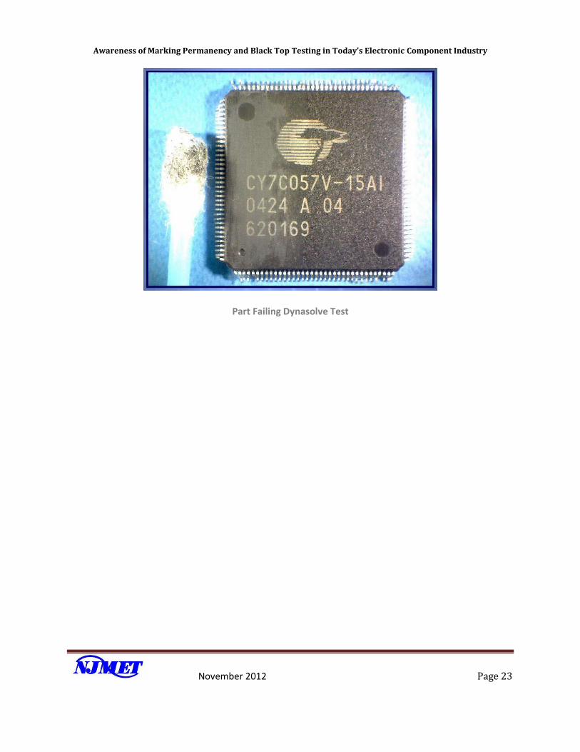
Part Failing Dynasolve Test
Awareness of Marking Permanency and Black Top Testing in Today’s Electronic Component Industry
November 2012 Page 24
Appendix 3: Original Certificate of Conformance