aviiva em2/em4 user manual - teledyne-e2v.com · aviiva® em1 gige 6 e2v semiconductors sas 2014...
TRANSCRIPT
1 e2v semiconductors SAS 2014
AVIIVA EM1 GigE Line Scan Monochrome Camera
User Manual
AVIIVA® EM1 Line Scan GigE Camera
2 e2v semiconductors SAS 2014
Summary 1 CAMERA OVERVIEW ................................................................................. 5
1.1 Features ........................................................................................................................................................ 5
1.2 Key Specifications ......................................................................................................................................... 5
1.2.1 Machine Vision Versions (BA0) ................................................................................................................................................. 5
1.2.2 OCT/Spectrometer versions (BA9) ........................................................................................................................................... 6
1.2.3 Common Characteristics .......................................................................................................................................................... 6
1.3 Description ................................................................................................................................................... 7
1.4 Typical Applications ...................................................................................................................................... 7
1.5 Models .......................................................................................................................................................... 7
2 CAMERA PERFORMANCES ........................................................................... 8
2.1 Camera Characterization .............................................................................................................................. 8
2.1.1 Machine Vision Versions (BA0) ................................................................................................................................................. 8
2.1.2 OCT/Spectrometer versions (BA9) ........................................................................................................................................... 8
2.2 Image Sensor ................................................................................................................................................ 9
2.3 Response & QE curves ................................................................................................................................ 10
2.3.1 Quantum Efficiency ................................................................................................................................................................ 10
2.3.2 Spectral Response .................................................................................................................................................................. 10
3 CAMERA HARDWARE INTERFACE ................................................................... 11
3.1 Mechanical Drawings ................................................................................................................................. 11
3.2 Input/output Connectors and LED ............................................................................................................. 12
Status LED Behaviour ........................................................................................................................................................................... 13
3.2.1 Power Connector .................................................................................................................................................................... 13
3.2.2 GPIO Connector ...................................................................................................................................................................... 14
3.2.3 Giga Ethernet Output ............................................................................................................................................................. 15
4 STANDARD CONFORMITY .......................................................................... 16
4.1 CE Conformity............................................................................................................................................. 16
4.2 FCC Conformity .......................................................................................................................................... 16
4.3 RoHs Conformity ........................................................................................................................................ 16
5 GETTING STARTED ................................................................................. 17
5.1.1 Out of the box ........................................................................................................................................................................ 17
5.2 Setting up in the system ............................................................................................................................. 18
6 CAMERA SOFTWARE INTERFACE.................................................................... 19
6.1 GigE Vision concepts .................................................................................................................................. 19
6.1.1 GenICam ................................................................................................................................................................................. 19
6.1.2 GenICam Standard .................................................................................................................................................................. 19
6.1.3 SFNC ....................................................................................................................................................................................... 19
6.2 Getting started with GigE Vision interface ................................................................................................. 20
6.2.1 Network setup ....................................................................................................................................................................... 20
6.2.2 Software installation ............................................................................................................................................................. 20
6.2.3 Interactive camera control ..................................................................................................................................................... 21
AVIIVA® EM1 Line Scan GigE Camera
3 e2v semiconductors SAS 2014
6.3 Camera Commands .................................................................................................................................... 23
6.3.1 How to Read the Tables of Parameters below? .................................................................................................................... 24
6.3.2 TransportLayerControl .......................................................................................................................................................... 25
6.3.3 DeviceControl ........................................................................................................................................................................ 29
6.3.4 ImageFormatControl ............................................................................................................................................................. 30
6.3.5 Privilege (Non SFNC) .............................................................................................................................................................. 32
6.3.6 Status (Non SFNC).................................................................................................................................................................. 32
6.3.7 .................................................................................................................................................................................................... 33
6.3.8 AcquisitionControl ................................................................................................................................................................. 34
6.3.8.1 Trigger Presets ...................................................................................................................................................... 37
6.3.9 DigitalIOControl ...................................................................................................................................................................... 41
6.3.10 CounterAndTimerControl.................................................................................................................................................. 43
6.3.11 AnalogControl ................................................................................................................................................................... 47
6.3.11.1 Analog Gain ........................................................................................................................................................... 49
6.3.11.2 Digital Gain & Offset (Contrast Expansion) ........................................................................................................... 49
6.3.11.3 Tap Balance ........................................................................................................................................................... 50
6.3.12 FlatFieldCorrectionControl ................................................................................................................................................. 51
6.3.13 LUTControl ........................................................................................................................................................................ 56
6.3.14 Statistics and Line Profile .................................................................................................................................................. 58
6.3.15 SaveRestoreSettings .......................................................................................................................................................... 60
6.3.16 FreeArea ............................................................................................................................................................................. 61
6.4 Packet_Resend mechanism........................................................................................................................ 61
7 APPENDIX A : Test Patterns ........................................................................ 62
7.1 Test Pattern 1 : Vertical wave .................................................................................................................... 62
7.2 Test Pattern 2 : In 8 bits format ................................................................................................................. 62
7.2.1 512 Pixels ............................................................................................................................................................................... 62
7.2.2 1024 Pixels ............................................................................................................................................................................. 62
7.2.3 2048 Pixels ............................................................................................................................................................................. 63
7.2.4 4096 Pixels ............................................................................................................................................................................. 63
7.3 Test Pattern 2 : In 12 bits format ............................................................................................................... 64
7.3.1 512 Pixels ............................................................................................................................................................................... 64
7.3.2 1024 Pixels ............................................................................................................................................................................. 64
7.3.3 2048 Pixels ............................................................................................................................................................................. 65
7.3.4 4096 Pixels ............................................................................................................................................................................. 65
8 APPENDIX B : Thermal Management ............................................................... 66
8.1 Heat Sinks ................................................................................................................................................... 66
8.2 Temperature dropping ............................................................................................................................... 67
8.3 Performance curves versus Temperature .................................................................................................. 68
9 APPENDIX C : Optical Mounts available ............................................................. 70
9.1 F-Mount ...................................................................................................................................................... 70
9.2 C-Mount ..................................................................................................................................................... 71
9.3 T2 & M42x1 Mounts ................................................................................................................................... 72
10 APPENDIX E : Index ............................................................................. 73

AVIIVA® EM1 Line Scan GigE Camera
4 e2v semiconductors SAS 2014
11 APPENDIX E : Revision History ................................................................... 76
AVIIVA® EM1 GigE
5 e2v semiconductors SAS 2014
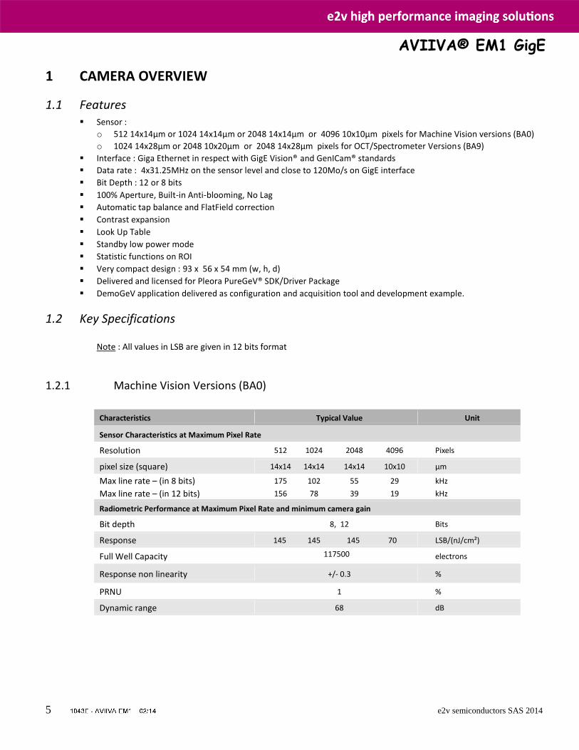
1 CAMERA OVERVIEW
1.1 Features Sensor :
o 512 14x14µm or 1024 14x14µm or 2048 14x14µm or 4096 10x10µm pixels for Machine Vision versions (BA0)
o 1024 14x28µm or 2048 10x20µm or 2048 14x28µm pixels for OCT/Spectrometer Versions (BA9)
Interface : Giga Ethernet in respect with GigE Vision® and GenICam® standards
Data rate : 4x31.25MHz on the sensor level and close to 120Mo/s on GigE interface
Bit Depth : 12 or 8 bits
100% Aperture, Built-in Anti-blooming, No Lag
Automatic tap balance and FlatField correction
Contrast expansion
Look Up Table
Standby low power mode
Statistic functions on ROI
Very compact design : 93 x 56 x 54 mm (w, h, d)
Delivered and licensed for Pleora PureGeV® SDK/Driver Package
DemoGeV application delivered as configuration and acquisition tool and development example.
1.2 Key Specifications Note : All values in LSB are given in 12 bits format
1.2.1 Machine Vision Versions (BA0)
Characteristics Typical Value Unit
Sensor Characteristics at Maximum Pixel Rate
Resolution 512 1024 2048 4096 Pixels
pixel size (square) 14x14 14x14 14x14 10x10 µm
Max line rate – (in 8 bits) 175 102 55 29 kHz
Max line rate – (in 12 bits) 156 78 39 19 kHz
Radiometric Performance at Maximum Pixel Rate and minimum camera gain
Bit depth 8, 12 Bits
Response 145 145 145 70 LSB/(nJ/cm²)
Full Well Capacity 117500
electrons
Response non linearity +/- 0.3 %
PRNU 1 %
Dynamic range 68 dB
AVIIVA® EM1 GigE
6 e2v semiconductors SAS 2014
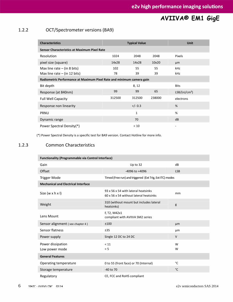
1.2.2 OCT/Spectrometer versions (BA9)
Characteristics Typical Value Unit
Sensor Characteristics at Maximum Pixel Rate
Resolution 1024 2048 2048 Pixels
pixel size (square) 14x28 14x28 10x20 µm
Max line rate – (in 8 bits) 102 55 55 kHz
Max line rate – (in 12 bits) 78 39 39 kHz
Radiometric Performance at Maximum Pixel Rate and minimum camera gain
Bit depth 8, 12 Bits
Response (at 840nm) 99 99 65
LSB/(nJ/cm²)
Full Well Capacity 312500 312500 238000
electrons
Response non linearity +/- 0.3 %
PRNU 1 %
Dynamic range 70 dB
Power Spectral Density(*) < 10 -
(*) Power Spectral Density is a specific test for BA9 version. Contact Hotline for more info.
1.2.3 Common Characteristics
Functionality (Programmable via Control Interface)
Gain Up to 32 dB
Offset -4096 to +4096 LSB
Trigger Mode Timed (Free run) and triggered (Ext Trig, Ext ITC) modes
Mechanical and Electrical Interface
Size (w x h x l) 93 x 56 x 54 with lateral heatsinks
60 x 56 x 54 without lateral heatsinks mm
Weight 310 (without mount but includes lateral heatsinks)
g
Lens Mount
F, T2, M42x1 compliant with AVIIVA SM2 series
Sensor alignment ( see chapter 4 ) ±100 µm
Sensor flatness ±35 µm
Power supply Single 12 DC to 24 DC V
Power dissipation
Low power mode
< 11
< 5
W
W
General Features
Operating temperature 0 to 55 (front face) or 70 (Internal) °C
Storage temperature -40 to 70 °C
Regulatory CE, FCC and RoHS compliant
AVIIVA® EM1 GigE
7 e2v semiconductors SAS 2014
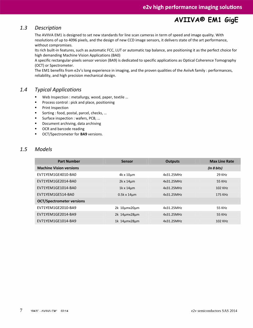
1.3 Description The AVIIVA EM1 is designed to set new standards for line scan cameras in term of speed and image quality. With resolutions of up to 4096 pixels, and the design of new CCD image sensors, it delivers state of the art performance, without compromises. Its rich built-in features, such as automatic FCC, LUT or automatic tap balance, are positioning it as the perfect choice for high demanding Machine Vision Applications (BA0) A specific rectangular-pixels sensor version (BA9) is dedicated to specific applications as Optical Coherence Tomography (OCT) or Spectrometer. The EM1 benefits from e2v’s long experience in imaging, and the proven qualities of the AviivA family : performances, reliability, and high precision mechanical design.
1.4 Typical Applications Web Inspection : metallurgy, wood, paper, textile …
Process control : pick and place, positioning
Print Inspection
Sorting : food, postal, parcel, checks, …
Surface inspection : wafers, PCB, …
Document archiving, data archiving
OCR and barcode reading
OCT/Spectrometer for BA9 versions.
1.5 Models
Part Number Sensor Outputs Max Line Rate
Machine Vision versions (In 8 bits)
EV71YEM1GE4010-BA0 4k x 10µm 4x31.25MHz 29 KHz
EV71YEM1GE2014-BA0 2k x 14µm 4x31.25MHz 55 KHz
EV71YEM1GE1014-BA0 1k x 14µm 4x31.25MHz 102 KHz
EV71YEM1GE514-BA0 0.5k x 14µm 4x31.25MHz 175 KHz
OCT/Spectrometer versions
EV71YEM1GE2010-BA9 2k 10µmx20µm 4x31.25MHz 55 KHz
EV71YEM1GE2014-BA9 2k 14µmx28µm 4x31.25MHz 55 KHz
EV71YEM1GE1014-BA9 1k 14µmx28µm 4x31.25MHz 102 KHz
AVIIVA® EM1 GigE
8 e2v semiconductors SAS 2014
2 CAMERA PERFORMANCES
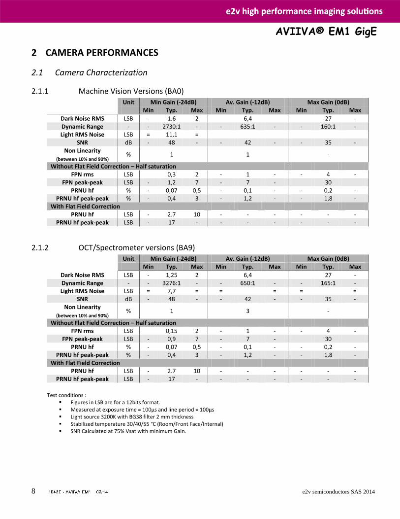
2.1 Camera Characterization
2.1.1 Machine Vision Versions (BA0) Unit Min Gain (-24dB) Av. Gain (-12dB) Max Gain (0dB) Min Typ. Max Min Typ. Max Min Typ. Max
Dark Noise RMS LSB - 1.6 2 6,4 27 - Dynamic Range - - 2730:1 - - 635:1 - - 160:1 - Light RMS Noise LSB = 11,1 =
SNR dB - 48 - - 42 - - 35 - Non Linearity
(between 10% and 90%) % 1 1 -
Without Flat Field Correction – Half saturation FPN rms LSB 0,3 2 - 1 - - 4 -
FPN peak-peak LSB - 1,2 7 - 7 - 30 PRNU hf % - 0,07 0,5 - 0,1 - - 0,2 -
PRNU hf peak-peak % - 0,4 3 - 1,2 - - 1,8 - With Flat Field Correction
PRNU hf LSB - 2.7 10 - - - - - - PRNU hf peak-peak LSB - 17 - - - - - - -
2.1.2 OCT/Spectrometer versions (BA9) Unit Min Gain (-24dB) Av. Gain (-12dB) Max Gain (0dB) Min Typ. Max Min Typ. Max Min Typ. Max
Dark Noise RMS LSB - 1,25 2 6,4 27 - Dynamic Range - - 3276:1 - - 650:1 - - 165:1 - Light RMS Noise LSB = 7,7 = = = = =
SNR dB - 48 - - 42 - - 35 - Non Linearity
(between 10% and 90%) % 1 3 -
Without Flat Field Correction – Half saturation FPN rms LSB 0,15 2 - 1 - - 4 -
FPN peak-peak LSB - 0,9 7 - 7 - 30 PRNU hf % - 0,07 0,5 - 0,1 - - 0,2 -
PRNU hf peak-peak % - 0,4 3 - 1,2 - - 1,8 - With Flat Field Correction
PRNU hf LSB - 2.7 10 - - - - - - PRNU hf peak-peak LSB - 17 - - - - - - -
Test conditions :
Figures in LSB are for a 12bits format. Measured at exposure time = 100µs and line period = 100µs Light source 3200K with BG38 filter 2 mm thickness Stabilized temperature 30/40/55 °C (Room/Front Face/Internal) SNR Calculated at 75% Vsat with minimum Gain.
AVIIVA® EM1 GigE
9 e2v semiconductors SAS 2014
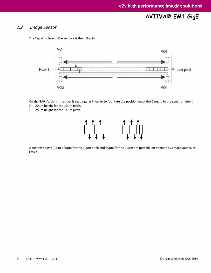
2.2 Image Sensor
The Tap structure of the sensors is the following :
On the BA9 Versions, the pixel is rectangular in order to facilitate the positioning of the Camera in the spectrometer : 20µm height for the 10µm pitch. 28µm height for the 14µm pitch. A custom height (up to 100µm for the 10µm pitch and 50µm for the 14µm are possible on demand : Contact your sales Office.
AVIIVA® EM1 GigE
10 e2v semiconductors SAS 2014
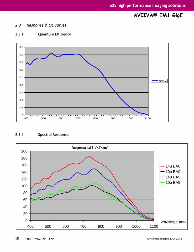
2.3 Response & QE curves
2.3.1 Quantum Efficiency
2.3.2 Spectral Response
0
0,1
0,2
0,3
0,4
0,5
0,6
0,7
0,8
0,9
400 500 600 700 800 900 1000 1100
QE(%)
0
20
40
60
80
100
120
140
160
180
200
400 500 600 700 800 900 1000 1100
14µ BA0
10µ BA0
14µ BA9
10µ BA9
Wavelength (nm)
Response LSB /nJ/cm²
AVIIVA® EM1 GigE
11 e2v semiconductors SAS 2014
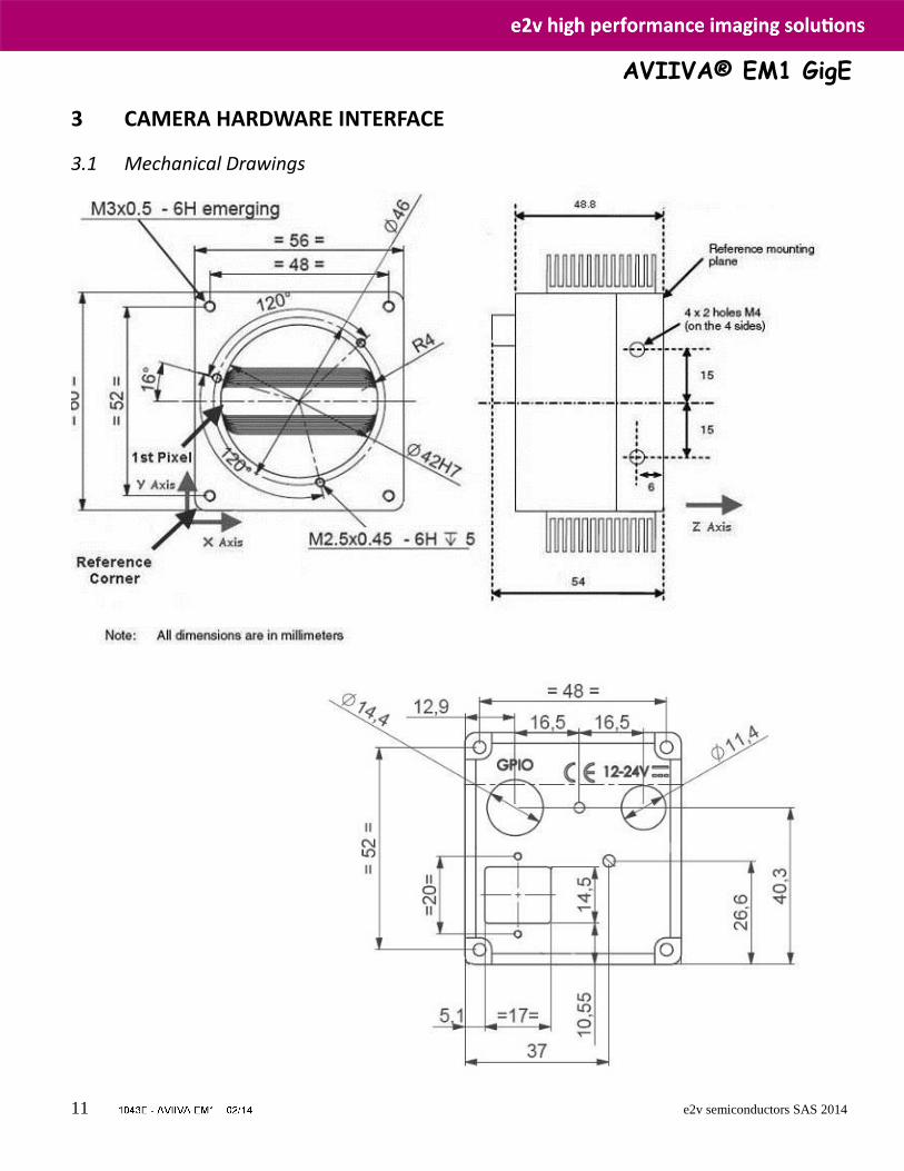
3 CAMERA HARDWARE INTERFACE
3.1 Mechanical Drawings
AVIIVA® EM1 GigE
12 e2v semiconductors SAS 2014
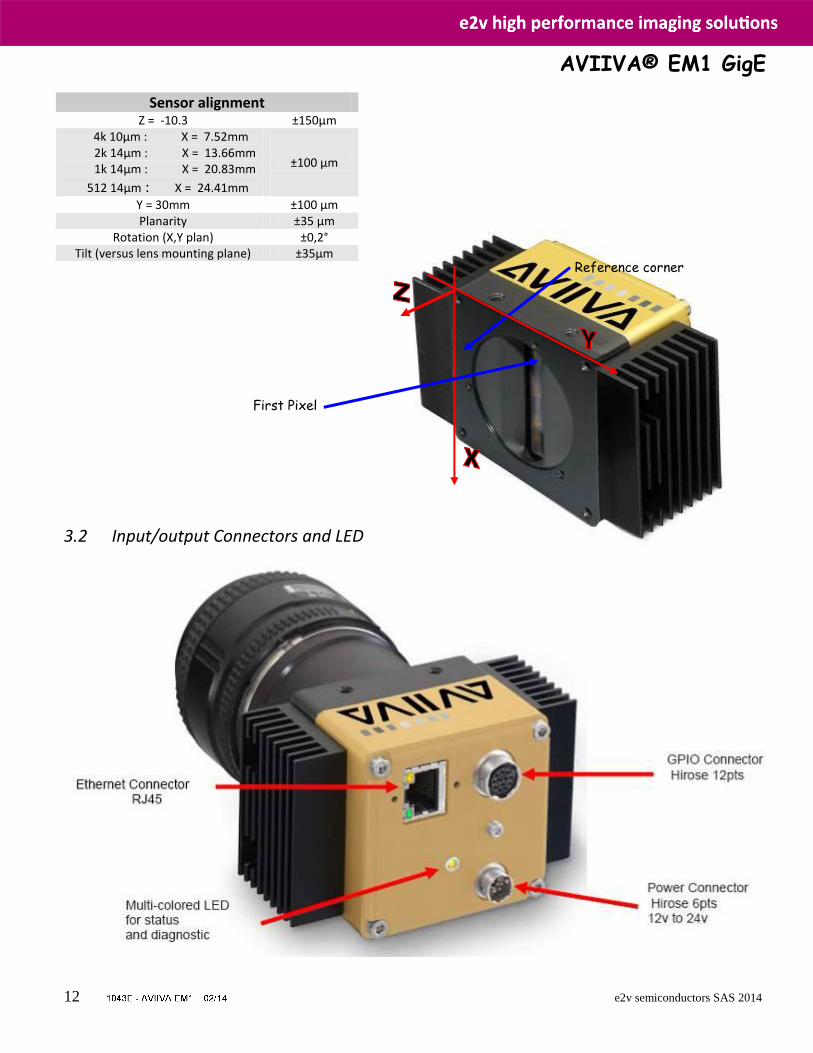
3.2 Input/output Connectors and LED
Sensor alignment Z = -10.3 ±150µm
4k 10µm : X = 7.52mm 2k 14µm : X = 13.66mm 1k 14µm : X = 20.83mm
512 14µm : X = 24.41mm
±100 µm
Y = 30mm ±100 µm Planarity ±35 µm
Rotation (X,Y plan) ±0,2° Tilt (versus lens mounting plane) ±35µm
Reference corner
First Pixel
AVIIVA® EM1 GigE
13 e2v semiconductors SAS 2014
Status LED Behaviour After less than 2 seconds of power establishment, the LED first lights up in ORANGE. Then after a Maximum of 30 seconds, the LED must turn in a following colour :
Colour and state Meaning Green and continuous OK
Green and blinking slowly Waiting for Ext Trig (Trig1 and/or Trig2)
Red and continuous Camera out of order : Internal firmware error
Orange and continuous Initialisation phase
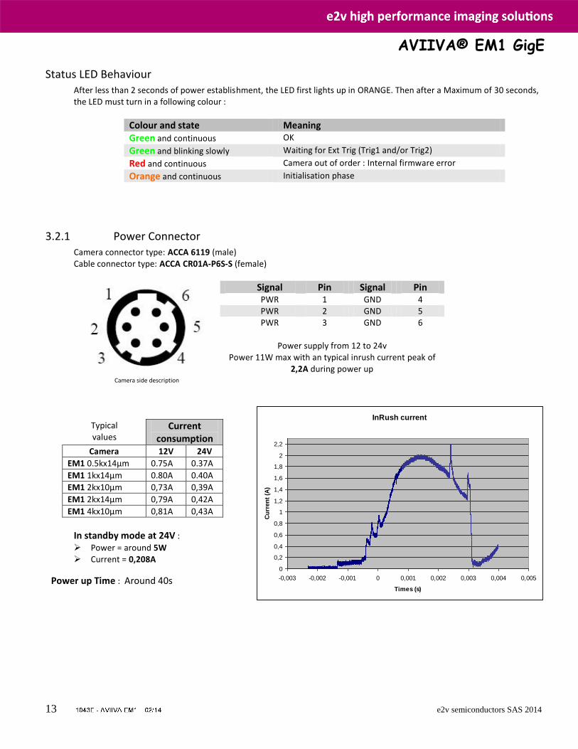
3.2.1 Power Connector Camera connector type: ACCA 6119 (male) Cable connector type: ACCA CR01A-P6S-S (female)
Camera side description
Signal Pin Signal Pin PWR 1 GND 4 PWR 2 GND 5 PWR 3 GND 6
Power supply from 12 to 24v
Power 11W max with an typical inrush current peak of 2,2A during power up
Typical values
Current consumption
Camera 12V 24V
EM1 0.5kx14µm 0.75A 0.37A
EM1 1kx14µm 0.80A 0.40A
EM1 2kx10µm 0,73A 0,39A
EM1 2kx14µm 0,79A 0,42A
EM1 4kx10µm 0,81A 0,43A
In standby mode at 24V :
Power = around 5W Current = 0,208A
Power up Time : Around 40s
InRush current
0
0,2
0,4
0,6
0,8
1
1,2
1,4
1,6
1,8
2
2,2
-0,003 -0,002 -0,001 0 0,001 0,002 0,003 0,004 0,005
Times (s)
Cu
rren
t (A
)
AVIIVA® EM1 GigE
14 e2v semiconductors SAS 2014
1 2 3 4 5 6 7 8 9 10 11 12
47Ω 47Ω
22Ω
I/O connector
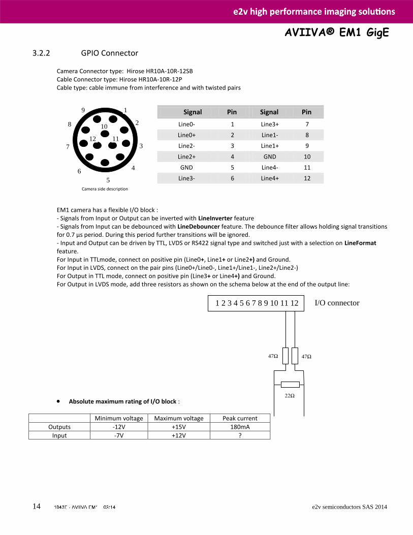
3.2.2 GPIO Connector
Camera Connector type: Hirose HR10A-10R-12SB Cable Connector type: Hirose HR10A-10R-12P Cable type: cable immune from interference and with twisted pairs
Camera side description
Signal Pin Signal Pin
Line0- 1 Line3+ 7
Line0+ 2 Line1- 8
Line2- 3 Line1+ 9
Line2+ 4 GND 10
GND 5 Line4- 11
Line3- 6 Line4+ 12
EM1 camera has a flexible I/O block : - Signals from Input or Output can be inverted with LineInverter feature - Signals from Input can be debounced with LineDebouncer feature. The debounce filter allows holding signal transitions for 0.7 µs period. During this period further transitions will be ignored. - Input and Output can be driven by TTL, LVDS or RS422 signal type and switched just with a selection on LineFormat feature. For Input in TTLmode, connect on positive pin (Line0+, Line1+ or Line2+) and Ground. For Input in LVDS, connect on the pair pins (Line0+/Line0-, Line1+/Line1-, Line2+/Line2-) For Output in TTL mode, connect on positive pin (Line3+ or Line4+) and Ground. For Output in LVDS mode, add three resistors as shown on the schema below at the end of the output line:
Absolute maximum rating of I/O block :
Minimum voltage Maximum voltage Peak current
Outputs -12V +15V 180mA
Input -7V +12V ?
1
2
3
4
5
6
7
8
9
10
11 12
AVIIVA® EM1 GigE
15 e2v semiconductors SAS 2014
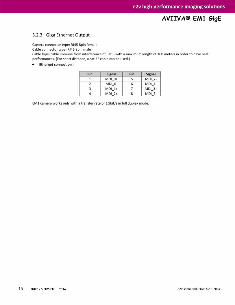
3.2.3 Giga Ethernet Output
Camera connector type: RJ45 8pin female Cable connector type: RJ45 8pin male Cable type: cable immune from interference of Cat.6 with a maximum length of 100 meters in order to have best performances. (For short distance, a cat.5E cable can be used.)
Ethernet connection :
Pin Signal Pin Signal
1 MDI_0+ 5 MDI_2-
2 MDI_0- 6 MDI_1-
3 MDI_1+ 7 MDI_3+
4 MDI_2+ 8 MDI_3-
EM1 camera works only with a transfer rate of 1Gbit/s in full duplex mode.
AVIIVA® EM1 GigE
16 e2v semiconductors SAS 2014
4 STANDARD CONFORMITY The AVIIVA EM1 cameras have been tested using the following equipment: A shielded power supply cable An Ethernet Cable cat6
e2v recommends using the same configuration to ensure the compliance with the fol lowing standards.
4.1 CE Conformity The AVIIVA EM1 cameras comply with the requirements of the EMC (European) directive 2004/108/CE (EN50081-2, EN 61000-6-2). This device is a class A device. Operation of this equipment in a residential area is likely to cause harmful interference. In this case the
user will be required to correct the interference at his own expense.
4.2 FCC Conformity The AVIIVA EM1 cameras further comply with Part 15 of the FCC rules, which states that: Operation is subject to the following two conditions: This device may not cause harmful interference, and This device must accept any interference received, including interference that may cause undesired operation This equipment has been tested and found to comply with the limits for Class A digi tal device, pursuant to part 15 of the FCC rules. These limits are designed to provide reasonable protection against harmful interference when the equipment is operated in a commercial environment. This equipment generates, uses and can radiate radio frequency energy and, if not installed and used in accordance with the instruction manual, may cause harmful interference to radio communications. Operation of this equipment in a residential area is likely to cause harmful interference in which case the user will be required to correct the interference at his own expense.
Warning: Changes or modifications to this unit not expressly approved by the party responsible for compliance could void the user's authority to operate this equipment.
4.3 RoHs Conformity AVIIVA EM1 cameras comply with the requirements of the RoHS directive 2002/95/EC.
AVIIVA® EM1 GigE
17 e2v semiconductors SAS 2014
5 GETTING STARTED
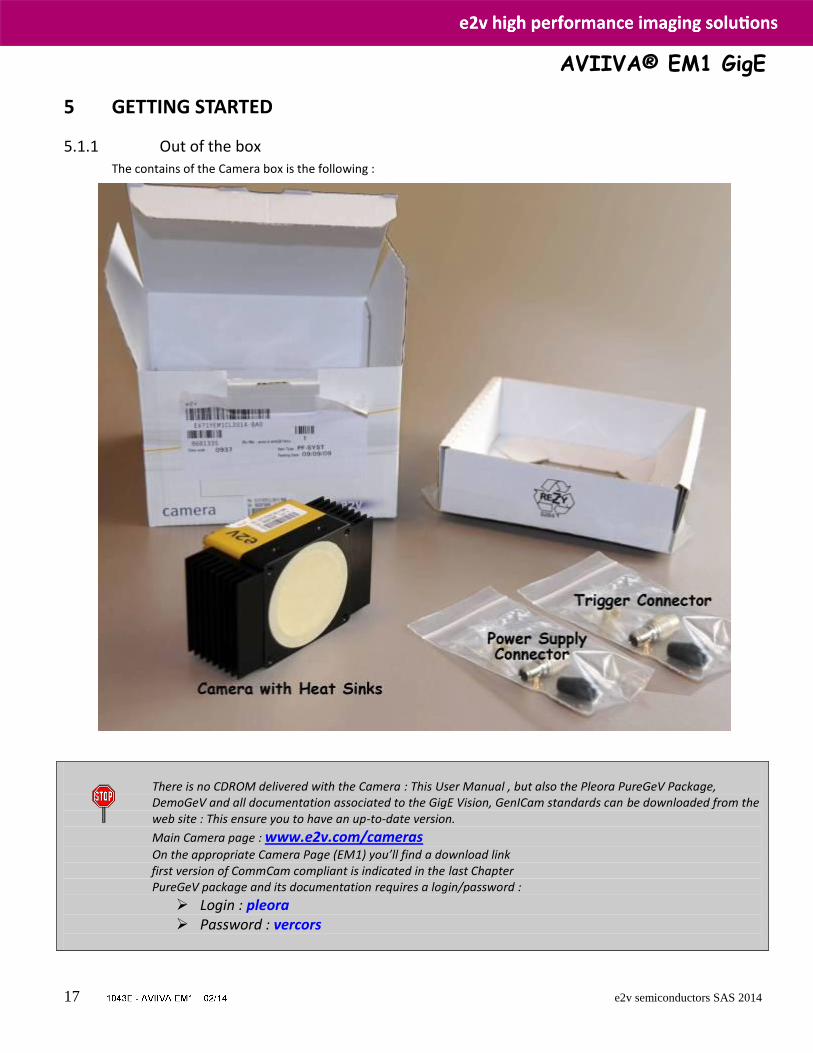
5.1.1 Out of the box The contains of the Camera box is the following :
There is no CDROM delivered with the Camera : This User Manual , but also the Pleora PureGeV Package, DemoGeV and all documentation associated to the GigE Vision, GenICam standards can be downloaded from the web site : This ensure you to have an up-to-date version.
Main Camera page : www.e2v.com/cameras
On the appropriate Camera Page (EM1) you’ll find a download link first version of CommCam compliant is indicated in the last Chapter PureGeV package and its documentation requires a login/password :
Login : pleora Password : vercors
AVIIVA® EM1 GigE
18 e2v semiconductors SAS 2014
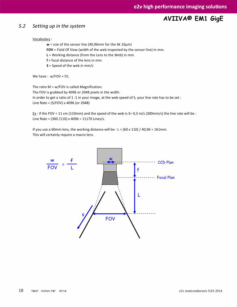
5.2 Setting up in the system
Vocabulary :
w = size of the sensor line (40,96mm for the 4k 10µm)
FOV = Field Of View (width of the web inspected by the sensor line) in mm.
L = Working distance (from the Lens to the Web) in mm.
f = focal distance of the lens in mm.
S = Speed of the web in mm/s
We have : w/FOV = f/L
The ratio M = w/FOV is called Magnification.
The FOV is grabbed by 4096 or 2048 pixels in the width.
In order to get a ratio of 1 :1 in your image, at the web speed of S, your line rate has to be set :
Line Rate = (S/FOV) x 4096 (or 2048)
Ex : if the FOV = 11 cm (110mm) and the speed of the web is S= 0,3 m/s (300mm/s) the line rate will be :
Line Rate = (300 /110) x 4096 = 11170 Lines/s.
If you use a 60mm lens, the working distance will be : L = (60 x 110) / 40,96 = 161mm.
This will certainly require a macro lens.
FOV
Focal Plan
CCD Plan
f
L
w
s
w f FOV L
=

AVIIVA® EM1 GigE
19 e2v semiconductors SAS 2014
6 CAMERA SOFTWARE INTERFACE
6.1 GigE Vision concepts Camera interface is compliant with "Gigabit Ethernet Vision" (GigE Vision) or (GEV). GEV normalizes image transport and camera control communications over usual IP networks. Physical GEV carrier has a bandwidth of one gigabit per second (1Gbit/s). GEV is widely used by camera manufacturers and imaging software suppliers.
6.1.1 GenICam Camera interface is compliant with "Generic Interface for Cameras" (GenICam). GenICam normalizes the camera control interface with software application. The target is to have a single application controlling cameras from any model and brand the same way. It introduces the concept of user manual, not for humans but to software application. Application reads this user manual to control cameras. GenICam has 2 parts, "GenICam Standard" and "GenICam Standard Features Naming Convention" (SFNC)
6.1.2 GenICam Standard It normalizes the camera control rules. It can be considered as the grammar of the user manual. From programmer's point of view, all cameras are controlled with the same way by a single Software Developer’s Kit (SDK).
6.1.3 SFNC From vision point of view, camera feature names are standardized by SFNC. It can be considered as the vocabulary of the user manual. The SNFC 1.3 is available in the documentation pack of this Camera : You’ll find all the complementary details which could miss you in this manual.
AVIIVA® EM1 GigE
20 e2v semiconductors SAS 2014
6.2 Getting started with GigE Vision interface This chapter shows how to connect a GEV camera for the first time.
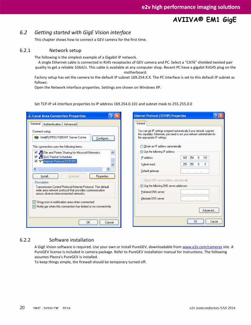
6.2.1 Network setup The following is the simplest example of a Gigabit IP network.
A single Ethernet cable is connected in RJ45 receptacles of GEV camera and PC. Select a "CAT6" shielded twisted pair quality to get a reliable 1Gbit/s. This cable is available at any computer shop. Recent PC have a gigabit RJG45 plug on the
motherboard. Factory setup has set the camera to the default IP subnet 169.254.X.X. The PC interface is set to this default IP subnet as follows: Open the Network interface properties. Settings are shown on Windows XP.
Set TCP-IP v4 interface properties to IP address 169.254.0.101 and subnet mask to 255.255.0.0
6.2.2 Software installation A GigE Vision software is required. Use your own or install PureGEV, downloadable from www.e2v.com/cameras site. A PureGEV license is included in camera package. Refer to PureGEV installation manual for instructions. The following assumes Pleora's PureGEV is installed. To keep things simple, the firewall should be temporary turned off.
AVIIVA® EM1 GigE
21 e2v semiconductors SAS 2014
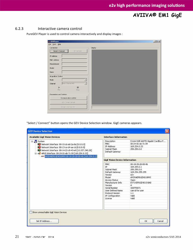
6.2.3 Interactive camera control PureGEV Player is used to control camera interactively and display images :
"Select / Connect" button opens the GEV Device Selection window. GigE cameras appears.
AVIIVA® EM1 GigE
22 e2v semiconductors SAS 2014
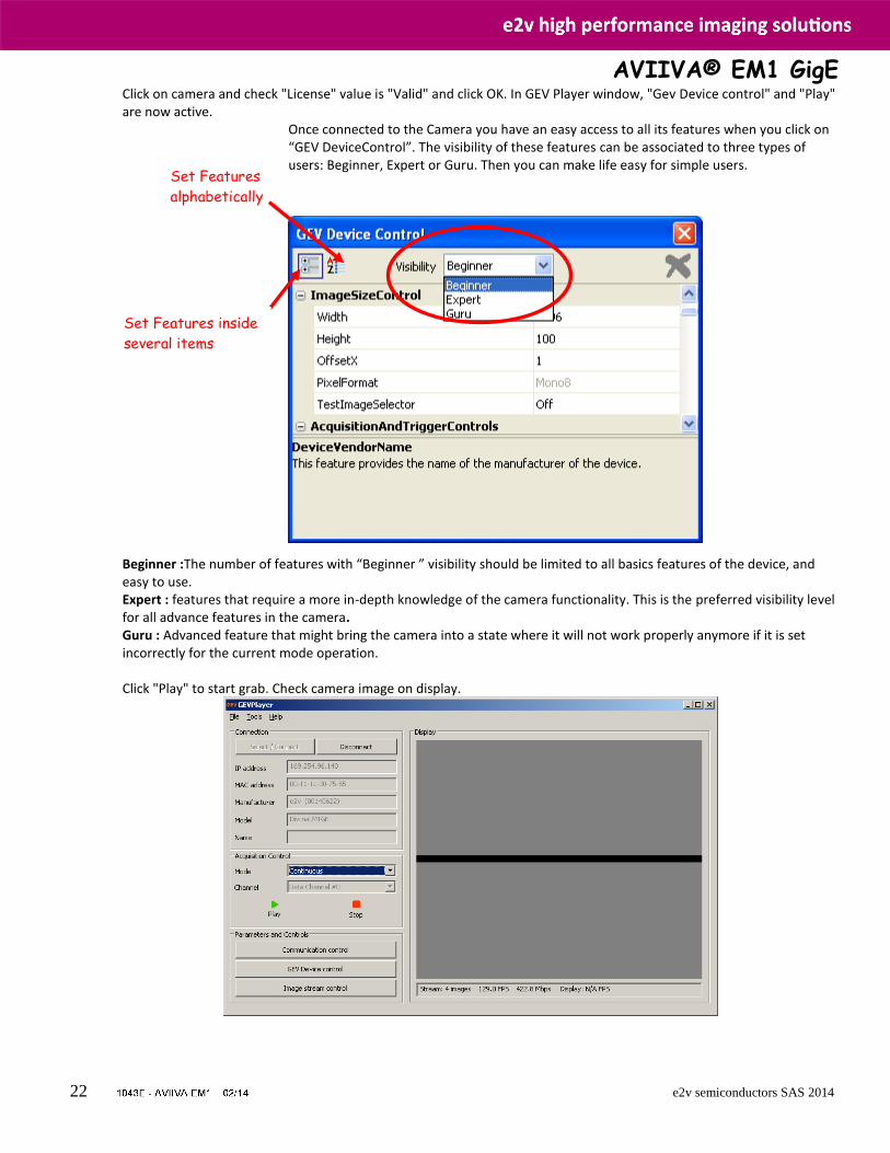
Click on camera and check "License" value is "Valid" and click OK. In GEV Player window, "Gev Device control" and "Play" are now active.
Once connected to the Camera you have an easy access to all its features when you click on “GEV DeviceControl”. The visibility of these features can be associated to three types of users: Beginner, Expert or Guru. Then you can make life easy for simple users.
Beginner :The number of features with “Beginner ” visibility should be limited to all basics features of the device, and easy to use. Expert : features that require a more in-depth knowledge of the camera functionality. This is the preferred visibility level for all advance features in the camera. Guru : Advanced feature that might bring the camera into a state where it will not work properly anymore if it is set incorrectly for the current mode operation. Click "Play" to start grab. Check camera image on display.
Set Features inside
several items
Set Features
alphabetically
Set Features inside
several items
AVIIVA® EM1 GigE
23 e2v semiconductors SAS 2014
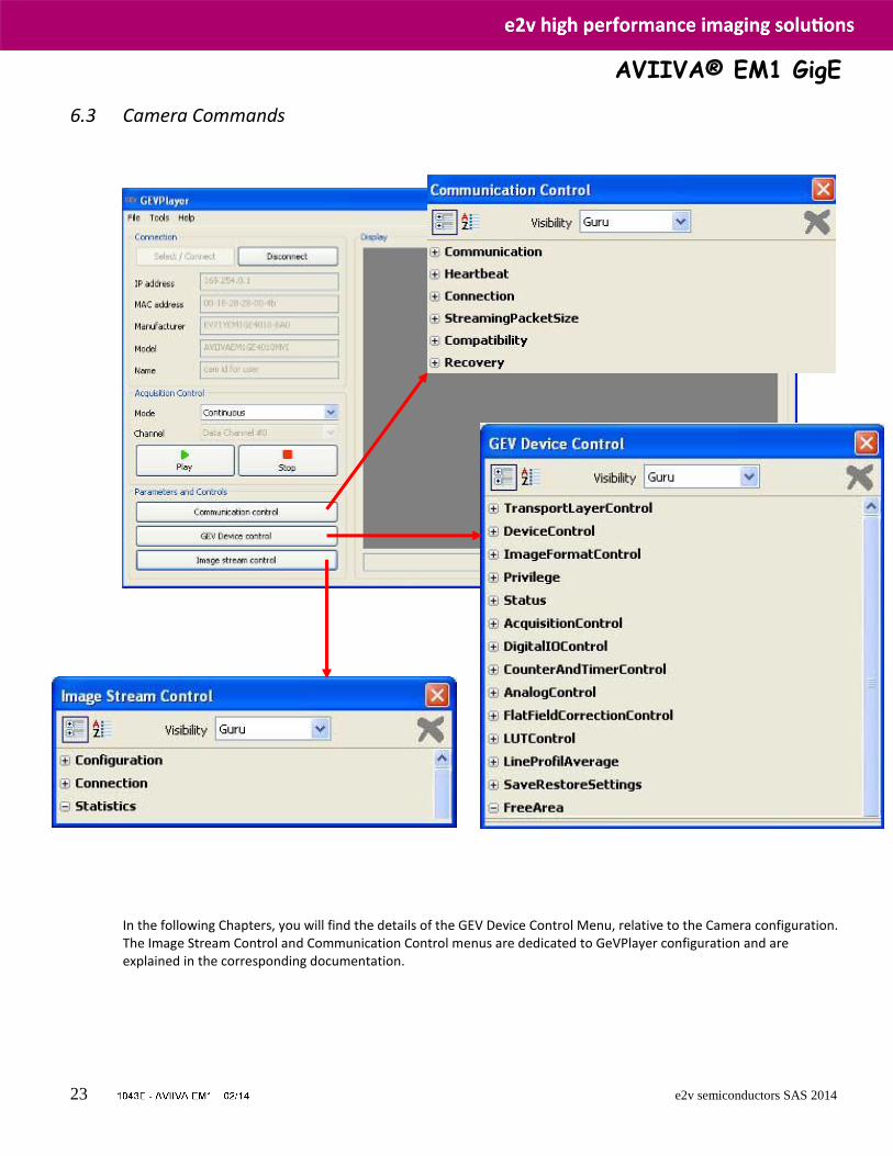
6.3 Camera Commands In the following Chapters, you will find the details of the GEV Device Control Menu, relative to the Camera configuration. The Image Stream Control and Communication Control menus are dedicated to GeVPlayer configuration and are explained in the corresponding documentation.
AVIIVA® EM1 GigE
24 e2v semiconductors SAS 2014
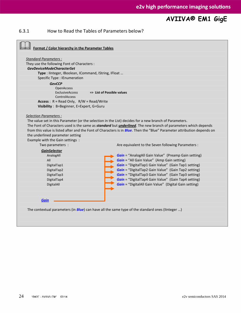
6.3.1 How to Read the Tables of Parameters below?
Format / Color hierarchy in the Parameter Tables
Standard Parameters : They use the following Font of Characters : GevDeviceModeCharacterSet
Type : IInteger, IBoolean, ICommand, IString, IFloat … Specific Type : IEnumeration
GevCCP OpenAccess ExclusiveAccess => List of Possible values ControlAccess
Access : R = Read Only, R/W = Read/Write Visibility : B=Beginner, E=Expert, G=Guru
Selection Parameters : The value set in this Parameter (or the selection in the List) decides for a new branch of Parameters. The Font of Characters used is the same as standard but underlined. The new branch of parameters which depends from this value is listed after and the Font of Characters is in Blue. Then the “Blue” Parameter attribution depends on the underlined parameter setting Example with the Gain settings : Two parameters : Are equivalent to the Seven following Parameters :
GainSelector AnalogAll Gain = “AnalogAll Gain Value” (Preamp Gain setting)
All Gain = “All Gain Value” (Amp Gain setting)
DigitalTap1 Gain = “DigitalTap1 Gain Value” (Gain Tap1 setting)
DigitalTap2 Gain = “DigitalTap2 Gain Value” (Gain Tap2 setting)
DigitalTap3 Gain = “DigitalTap3 Gain Value” (Gain Tap3 setting)
DigitalTap4 Gain = “DigitalTap4 Gain Value” (Gain Tap4 setting)
DigitalAll Gain = “DigitalAll Gain Value” (Digital Gain setting)
Gain
The contextual parameters (in Blue) can have all the same type of the standard ones (IInteger …)
AVIIVA® EM1 GigE
25 e2v semiconductors SAS 2014
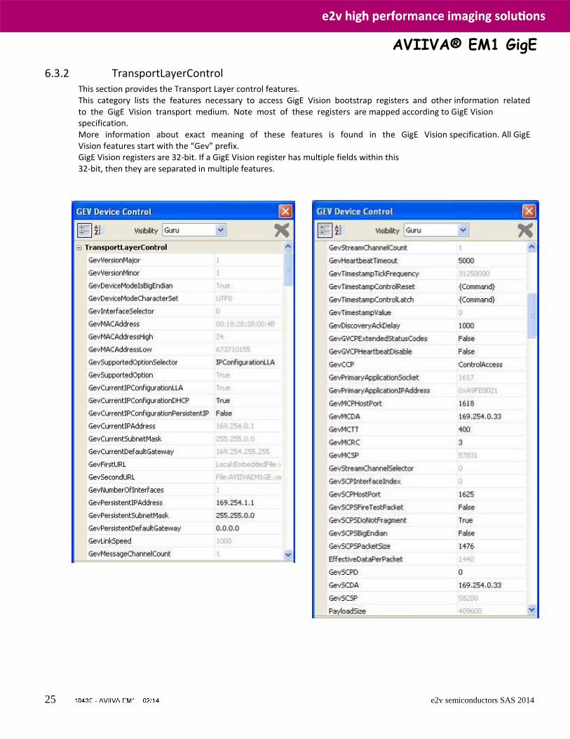
6.3.2 TransportLayerControl This section provides the Transport Layer control features. This category lists the features necessary to access GigE Vision bootstrap registers and other information related to the GigE Vision transport medium. Note most of these registers are mapped according to GigE Vision specification. More information about exact meaning of these features is found in the GigE Vision specification. All GigE Vision features start with the “Gev” prefix. GigE Vision registers are 32-bit. If a GigE Vision register has multiple fields within this 32-bit, then they are separated in multiple features.
AVIIVA® EM1 GigE
26 e2v semiconductors SAS 2014
Name Interface Access Visibility Description
GevVersionMajor IInteger R E Major version of the specification.
GevVersionMinor IInteger R E Minor version of the specification.
GevDeviceModeIsBigEndian IBoolean R G Endianess of the device registers.
GevDeviceModeCharacterSet IEnumeration R G Character set used by all the strings of the bootstrap registers.
GevInterfaceSelector IInteger R B Selects which physical network interface to control : Always 0 as only one network is available
GevMACAddress IInteger R B MAC address of the network interface.
GevMACAddressHigh IInteger R B High part of the MAC address of the network interface.
GevMACAddressLow IInteger R B Low part of the MAC address of the network interface.
GevCurrentIPConfigurationLLA IBoolean R/W B Indicates if Link Local Address IP configuration scheme is activated on the given network interface.
GevCurrentIPConfigurationDHCP IBoolean R/W B Indicates if DHCP IP configuration scheme is activated on the given network interface.
GevCurrentIPConfigurationPersistentIP IBoolean R/W B Indicates if PersistentIP configuration scheme is activated on the given network interface.
GevCurrentIPAddress IInteger R B Reports the IP address for the given network interface.
GevCurrentSubnetMask IInteger R B Provides the subnet mask of the given interface.
GevCurrentDefaultGateway IInteger R B Indicates the default gateway IP address to be used on the given network interface.
GevPersistentIPAddress IInteger R/W B Indicates the Persistent IP address for this network interface.
GevPersistentSubnetMask IInteger R/W B Indicates the Persistent subnet mask associated with the Persistent IP address on this network interface.
GevPersistentDefaultGateway IInteger R/W B Indicates the persistent default gateway for this network interface.
GevLinkSpeed IInteger R E Indicates the speed of transmission negotiated by the given network Interface in MBytes/s
AVIIVA® EM1 GigE
27 e2v semiconductors SAS 2014
Name Interface Access Visibility Description
GevSupportedOptionSelector IPConfigurationLLA IPConfigurationDHCP IPConfigurationPersistentIP CommandsConcatenation WriteMem PacketResend Event EventData PendingAck Action ExtendedStatusCodes DiscoveryAckDelayWritable DiscoveryAckDelay TestData ManifestTable CCPApplicationSocket LinkSpeed HeartbeatDisable SerialNumber UserDefinedName StreamChannelSourceSocket MessageChannelSourceSocket
IEnumeration R/W E Selects the GEV option to interrogate for existing support.
Answer is given in GevSupportedOption
GevSupportedOption IBoolean R E Returns if the selected GEV option is supported.
GevFirstURL IString R G Indicates the first URL to the XML device description file.
GevSecondURL IString R G Indicates the second URL to the XML device description file.
GevNumberOfInterfaces IInteger R E Indicates the number of physical network interfaces supported by this device.
GevMessageChannelCount IInteger R E Indicates the number of message channels supported by this device.
GevStreamChannelCount IInteger R E Indicates the number of stream channels supported by this device.
GevHeartbeatTimeout IInteger R/W G Indicates the current heartbeat timeout in milliseconds.
GevTimestampTickFrequency IInteger R E Indicates the number of timestamp ticks during 1 second (frequency in Hz).
GevTimestampControlReset ICommand W E Resets the Timestamp counter to 0.
GevTimestampControlLatch ICommand W E Latches current timestamp counter into GevTimestampValue.
GevTimestampValue IInteger R E Returns the latched 64-bit value of the timestamp counter.
GevDiscoveryAckDelay IInteger R/(W) E Indicates the maximum randomized delay the device will wait to acknowledge a discovery command in ms
GevGVCPExtendedStatusCodes IBoolean R/W G Enables genereation of extended status codes.
GevGVCPHeartbeatDisable IBoolean R/W E Disables the GVCP heartbeat.
AVIIVA® EM1 GigE
28 e2v semiconductors SAS 2014
Name Interface Access Visibility Description
GevCCP OpenAccess ExclusiveAccess ControlAccess
IEnumeration R/W G Controls the device access privilege of an application.
GevPrimaryApplicationSocket IInteger R G Returns the UDP source port of the primary application.
GevPrimaryApplicationIPAddress IInteger R G Returns the address of the primary application.
GevMCPHostPort IInteger R/W G Indicates the port to which the device must send messages.
GevMCDA IInteger R/W G Indicates the destination IP address for the message channel.
GevMCTT IInteger R/W G Provides the transmission timeout value in milliseconds.
GevMCRC IInteger R/W G Indicates the number of retransmissions allowed when a message channel message times out.
GevMCSP IInteger R G This feature indicates the source port for the message channel.
GevStreamChannelSelector IInteger R E Selects the stream channel to control. Always 0 as only one stream channel available.
GevSCPInterfaceIndex IInteger R G Index of network interface to use Always 0 as only one network available.
GevSCPHostPort IInteger R/W G Indicates the port to which the device must send data stream.
GevSCPSFireTestPacket IBoolean R/W G Sends a test packet.
GevSCPSDoNotFragment IBoolean R/W G The state of this feature is copied into the "do not fragment" bit of IP header of each stream packet.
GevSCPSBigEndian IBoolean R/W G Endianess of multi-byte pixel data for this stream.
GevSCPSPacketSize IInteger R/W E Specifies the stream packet size in bytes to send on this channel.
GevSCPD IInteger R/W E Indicates the delay (in timestamp counter unit) to insert between each packet for this stream channel.
GevSCDA IInteger R/W G Indicates the destination IP address for this stream channel.
GevSCSP IInteger R G Indicates the source port of the stream channel.
PayloadSize IInteger R E Provides the number of bytes transferred for each image or chunk on the stream channel in Bytes
Note : If the user has configured the camera front end, he can read from the back end which PayloadSize will be transferred for each image. This number covers all kind of data coming with the image, e.g. stamps etc. If the user allocates PayloadSize for each buffer he is insured that each frame will fit into his target buffers.
AVIIVA® EM1 GigE
29 e2v semiconductors SAS 2014
6.3.3 DeviceControl
Device control features provides general information and control for the device (camera) and its sensor. This is mainly used to identify the device during the enumeration process and to obtain information about the sensor resolution. Other information and controls pertaining to the general state of the device are also included in this category.
Name Interface Access Visibility Description
DeviceVendorName IString R B Name of the manufacturer of the device. DeviceModelName IString R B Model of the device. DeviceManufacturerInfo IString R B Manufacturer information about the device. DeviceID IString R E Device identifier (serial number). DeviceVersion IString R B Version of the device. DeviceFirmwareVersion IString R B Version of the firmware in the device. DeviceUserID IString R/W B User-programmable device identifier. ElectronicBoardID IString R B Electronic Board ID (NON SFNC) DeviceScanType
LineScan IEnumeration R E Scan type of the sensor. LineScan Only
DeviceMaxThroughput IInteger R E Maximum bandwidth of the data that can be streamed out of the device in Byte/s
DeviceRegistersCheck ICommand (R)/W E Perform the validation of the current register set for consistency.
DeviceRegistersValid IBoolean R E Returns if the current register set is valid and consistent.

AVIIVA® EM1 GigE
30 e2v semiconductors SAS 2014
6.3.4 ImageFormatControl
This section describes how to influence and determine the image size and format. It also provides the necessary information to acquire and to display the image data. The sensor provides SensorWidth time SensorHeight pixels. Note : The image outputted is necessary with a Width of SensorWidth as there is no Region of interest available. The Height parameter will give you the number of lines grabbed for each image. As some reception buffers are required on the Application side, the size of each of these buffers is defined by :
Width x Heigth x PixelFormat Each pixel in the image has a format defined by PixelFormat which fix both PixelSize and PixelCoding
Name Interface Access Visibility Description
SensorWidth IInteger R E Effective width of the sensor in pixels.
SensorHeight IInteger R E Effective height of the sensor in pixels.
WidthMax IInteger R E Maximum width (in pixels) of the image.
HeightMax IInteger R E Maximum height (in pixels) of the image.
Width IInteger R B Width of the Image provided by the device sensor (in pixels).
Height IInteger R/W B Height of the image provided by the device (in pixels).
PixelCoding Mono MonoPacked
IEnumeration R/(W) E Coding of the pixels in the image.
Depends on PixelFormat.
PixelSize Bpp8 Bpp12
IEnumeration R/(W) E Total size in bits of a pixel of the image. Depends on PixelFormat.
PixelColorFilter IEnumeration R E Type of color filter that is applied to the image. Always None
PixelFormat Mono8 Mono12
IEnumeration R/W B Format of the pixel to use for acquisition.
AVIIVA® EM1 GigE
31 e2v semiconductors SAS 2014
Name Interface Access Visibility Description
TestImageSelector Off GrayHorizontalRamp GrayDiagonalRampMoving
IEnumeration R/W B Selects the type of test image that is sent by the camera.
EnableEndOfLineData IBoolean R/W B Enable the addition of 2 x 32bits data at the end of each line
EnableEndOfLineData0Source Counter1 Counter2 Timer1 Timer2
IEnumeration R/W B Selects the source of first data of 32 to put at the end of each line
EnableEndOfLineData1Source Counter1 Counter2 Timer1 Timer2
IEnumeration R/W B Selects the source of second data of 32 to put at the end of each line
TestImageSelector : The GrayHorizontalRamp (test patterns) are different depending on the PixelFormat and the SensorSize. They are defined in details Appendix A of this document.
EndOfLineData : The User can put 2 words of 32bits each in addition at the end of each pixel line data. These words can be designed as the output of the two Counters or the two timers.
AVIIVA® EM1 GigE
32 e2v semiconductors SAS 2014
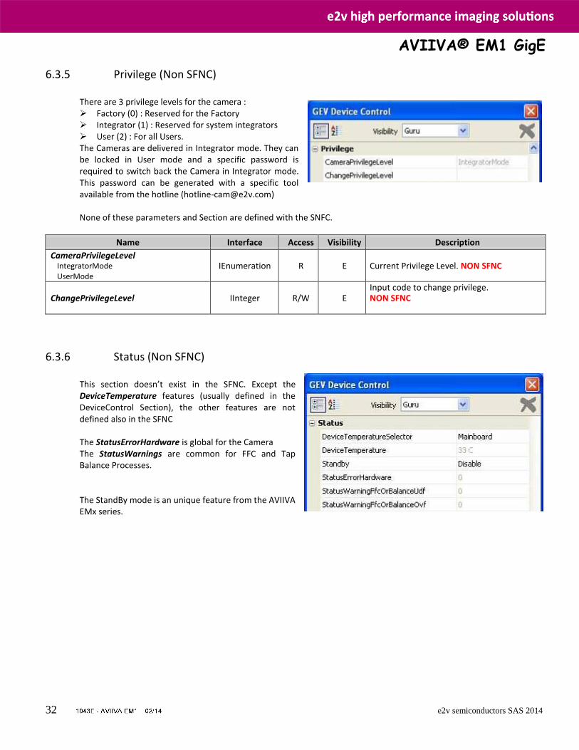
6.3.5 Privilege (Non SFNC)
There are 3 privilege levels for the camera : Factory (0) : Reserved for the Factory Integrator (1) : Reserved for system integrators User (2) : For all Users. The Cameras are delivered in Integrator mode. They can be locked in User mode and a specific password is required to switch back the Camera in Integrator mode. This password can be generated with a specific tool available from the hotline ([email protected])
None of these parameters and Section are defined with the SNFC.
Name Interface Access Visibility Description
CameraPrivilegeLevel IntegratorMode UserMode
IEnumeration R E Current Privilege Level. NON SFNC
ChangePrivilegeLevel IInteger R/W E Input code to change privilege. NON SFNC
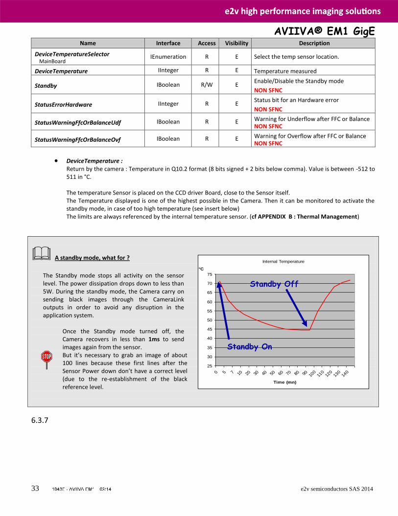
6.3.6 Status (Non SFNC)
This section doesn’t exist in the SFNC. Except the DeviceTemperature features (usually defined in the DeviceControl Section), the other features are not defined also in the SFNC The StatusErrorHardware is global for the Camera The StatusWarnings are common for FFC and Tap Balance Processes. The StandBy mode is an unique feature from the AVIIVA EMx series.
AVIIVA® EM1 GigE
33 e2v semiconductors SAS 2014
Name Interface Access Visibility Description
DeviceTemperatureSelector MainBoard
IEnumeration R E Select the temp sensor location.
DeviceTemperature IInteger R E Temperature measured
Standby IBoolean R/W E Enable/Disable the Standby mode
NON SFNC
StatusErrorHardware IInteger R E Status bit for an Hardware error
NON SFNC
StatusWarningFfcOrBalanceUdf IBoolean R E Warning for Underflow after FFC or Balance NON SFNC
StatusWarningFfcOrBalanceOvf IBoolean R E Warning for Overflow after FFC or Balance NON SFNC
DeviceTemperature : Return by the camera : Temperature in Q10.2 format (8 bits signed + 2 bits below comma). Value is between -512 to 511 in °C. The temperature Sensor is placed on the CCD driver Board, close to the Sensor itself. The Temperature displayed is one of the highest possible in the Camera. Then it can be monitored to activate the standby mode, in case of too high temperature (see insert below) The limits are always referenced by the internal temperature sensor. (cf APPENDIX B : Thermal Management)
A standby mode, what for ?
The Standby mode stops all activity on the sensor level. The power dissipation drops down to less than 5W. During the standby mode, the Camera carry on sending black images through the CameraLink outputs in order to avoid any disruption in the application system.
Once the Standby mode turned off, the Camera recovers in less than 1ms to send images again from the sensor. But it’s necessary to grab an image of about 100 lines because these first lines after the Sensor Power down don’t have a correct level (due to the re-establishment of the black reference level.
6.3.7
Internal Temperature
25
30
35
40
45
50
55
60
65
70
75
0 5 7 10 20 30 40 50 60 70 80 90 100
110
120
130
140
Time (mn)
°C
Standby Off
Standby On
AVIIVA® EM1 GigE
34 e2v semiconductors SAS 2014
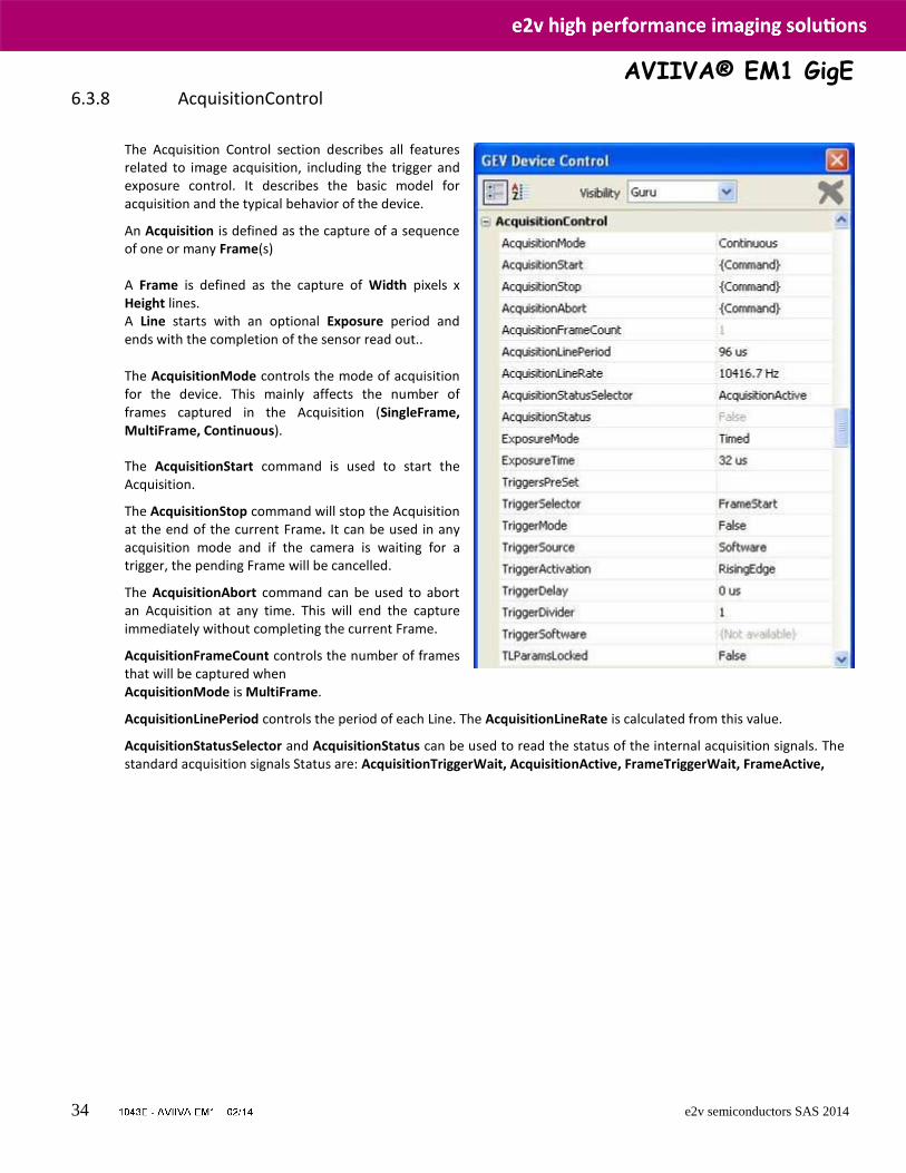
6.3.8 AcquisitionControl
The Acquisition Control section describes all features related to image acquisition, including the trigger and exposure control. It describes the basic model for acquisition and the typical behavior of the device. An Acquisition is defined as the capture of a sequence of one or many Frame(s) A Frame is defined as the capture of Width pixels x Height lines. A Line starts with an optional Exposure period and ends with the completion of the sensor read out..
The AcquisitionMode controls the mode of acquisition for the device. This mainly affects the number of frames captured in the Acquisition (SingleFrame, MultiFrame, Continuous). The AcquisitionStart command is used to start the Acquisition. The AcquisitionStop command will stop the Acquisition at the end of the current Frame. It can be used in any acquisition mode and if the camera is waiting for a trigger, the pending Frame will be cancelled. The AcquisitionAbort command can be used to abort an Acquisition at any time. This will end the capture immediately without completing the current Frame. AcquisitionFrameCount controls the number of frames that will be captured when AcquisitionMode is MultiFrame. AcquisitionLinePeriod controls the period of each Line. The AcquisitionLineRate is calculated from this value. AcquisitionStatusSelector and AcquisitionStatus can be used to read the status of the internal acquisition signals. The standard acquisition signals Status are: AcquisitionTriggerWait, AcquisitionActive, FrameTriggerWait, FrameActive,
AVIIVA® EM1 GigE
35 e2v semiconductors SAS 2014
Name Interface Access Visibility Description
AcquisitionMode SingleFrame MultiFrame Continuous
IEnumeration R/W B Sets the acquisition mode of the device.
AcquisitionStart ICommand (R)/W B Starts the Acquisition of the device.
AcquisitionStop ICommand (R)/W B Stops the Acquisition of the device at the end of the current Frame.
AcquisitionAbort ICommand (R)/W E Aborts the acquisition immediately.
AcquisitionFrameCount IInteger R/W B Number of frames to acquire in MultiFrame Acquisition mode.
AcquisitionLinePeriod IFloat R/W B Controls the line period (in µs)
AcquisitionLineRate IFloat R/W B Gives the equivalent line rate (in Hertz)
AcquisitionStatusSelector AcquisitionTriggerWait AcquisitionActive FrameTriggerWait FrameActive
IEnumeration R/W E Selects the internal acquisition signal to read using AcquisitionStatus.
AcquisitionStatus IBoolean R E Reads the state of the internal acquisition signal selected using AcquisitionStatusSelector.
ExposureMode Timed TriggerWidth TriggerControlled
IEnumeration R/W B Selects the type of trigger to configure.
ExposureTime IFloat R/W B Sets the internal exposure time of the camera (in µs)
TriggerPreset ContinuousTimedMode TriggeredTimedMode TriggeredTimedModeWithFrameTrigger TriggeredWidthMode TriggeredWidthModeWithFrameTrigger ITCMaxMode ITCMaxModeWithFrameTrigger ITCMode ITCModeWithFrameTrigger
IEnumeration R/W B NON SFNC
Sets automatically the camera in a list of Pre-selected Trigger modes equivalent to the existing CameraLink versions of e2v Cameras. See below for details of each mode.
AVIIVA® EM1 GigE
36 e2v semiconductors SAS 2014
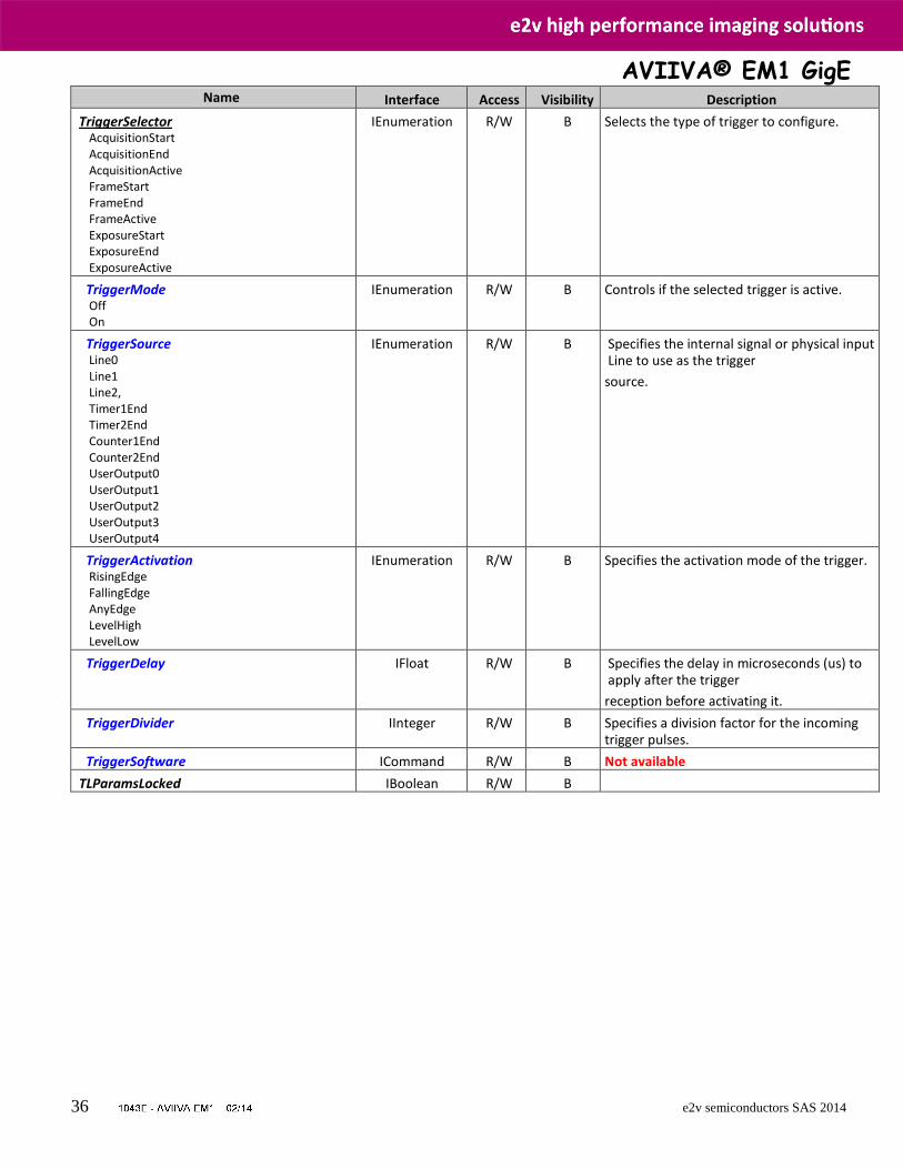
Name Interface Access Visibility Description
TriggerSelector AcquisitionStart AcquisitionEnd AcquisitionActive FrameStart FrameEnd FrameActive ExposureStart ExposureEnd ExposureActive
IEnumeration R/W B Selects the type of trigger to configure.
TriggerMode Off On
IEnumeration R/W B Controls if the selected trigger is active.
TriggerSource Line0 Line1 Line2, Timer1End Timer2End Counter1End Counter2End UserOutput0 UserOutput1 UserOutput2 UserOutput3 UserOutput4
IEnumeration R/W B Specifies the internal signal or physical input Line to use as the trigger
source.
TriggerActivation RisingEdge FallingEdge AnyEdge LevelHigh LevelLow
IEnumeration R/W B Specifies the activation mode of the trigger.
TriggerDelay IFloat R/W B Specifies the delay in microseconds (us) to apply after the trigger
reception before activating it.
TriggerDivider IInteger R/W B Specifies a division factor for the incoming trigger pulses.
TriggerSoftware ICommand R/W B Not available
TLParamsLocked IBoolean R/W B
AVIIVA® EM1 GigE
37 e2v semiconductors SAS 2014
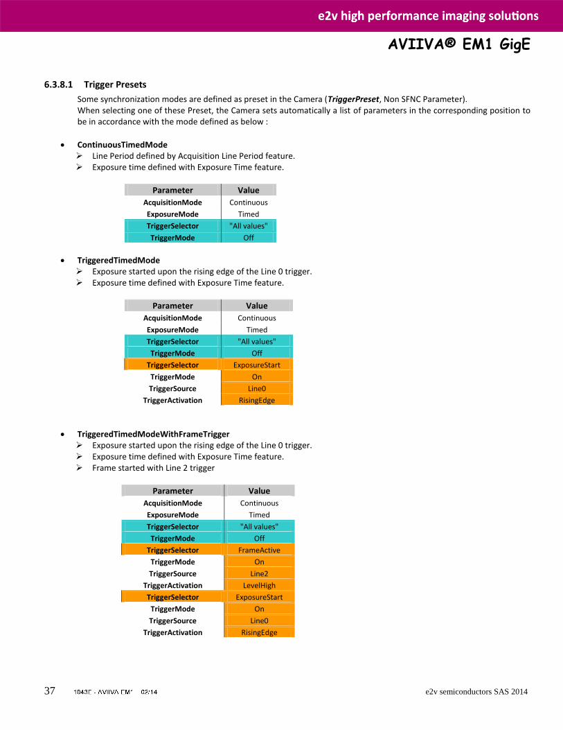
6.3.8.1 Trigger Presets
Some synchronization modes are defined as preset in the Camera (TriggerPreset, Non SFNC Parameter). When selecting one of these Preset, the Camera sets automatically a list of parameters in the corresponding position to be in accordance with the mode defined as below :
ContinuousTimedMode Line Period defined by Acquisition Line Period feature. Exposure time defined with Exposure Time feature.
Parameter Value
AcquisitionMode Continuous
ExposureMode Timed
TriggerSelector "All values"
TriggerMode Off
TriggeredTimedMode Exposure started upon the rising edge of the Line 0 trigger. Exposure time defined with Exposure Time feature.
Parameter Value
AcquisitionMode Continuous
ExposureMode Timed
TriggerSelector "All values"
TriggerMode Off
TriggerSelector ExposureStart
TriggerMode On
TriggerSource Line0
TriggerActivation RisingEdge
TriggeredTimedModeWithFrameTrigger Exposure started upon the rising edge of the Line 0 trigger. Exposure time defined with Exposure Time feature. Frame started with Line 2 trigger
Parameter Value
AcquisitionMode Continuous
ExposureMode Timed
TriggerSelector "All values"
TriggerMode Off
TriggerSelector FrameActive
TriggerMode On
TriggerSource Line2
TriggerActivation LevelHigh
TriggerSelector ExposureStart
TriggerMode On
TriggerSource Line0
TriggerActivation RisingEdge
AVIIVA® EM1 GigE
38 e2v semiconductors SAS 2014
TriggeredWidthMode Exposure started upon Line 0 trigger. Exposure time defined with Line0 trigger width
Parameter Value
AcquisitionMode Continuous
ExposureMode TriggerWidth
TriggerSelector "All values"
TriggerMode Off
TriggerSelector ExposureActive
TriggerMode On
TriggerSource Line0
TriggerActivation LevelHigh
TriggeredWidthModeWithFrameTrigger Exposure started upon Line 0 trigger. Exposure time defined with Line0 trigger width. The Frame is valid on the high level of the Line 2 trigger
Parameter Value
AcquisitionMode Continuous
ExposureMode TriggerWidth
TriggerSelector "All values"
TriggerMode Off
TriggerSelector FrameActive
TriggerMode On
TriggerSource Line2
TriggerActivation LevelHigh
TriggerSelector ExposureActive
TriggerMode On
TriggerSource Line0
TriggerActivation LevelHigh
AVIIVA® EM1 GigE
39 e2v semiconductors SAS 2014
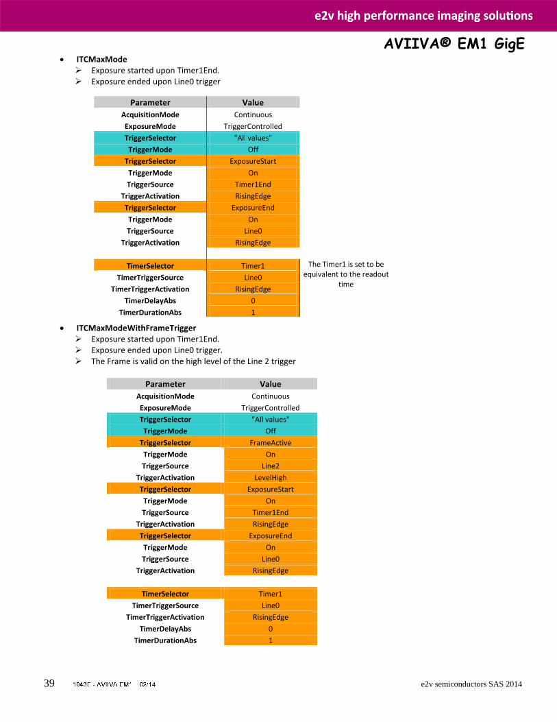
ITCMaxMode Exposure started upon Timer1End. Exposure ended upon Line0 trigger
ITCMaxModeWithFrameTrigger Exposure started upon Timer1End. Exposure ended upon Line0 trigger. The Frame is valid on the high level of the Line 2 trigger
Parameter Value
AcquisitionMode Continuous
ExposureMode TriggerControlled
TriggerSelector "All values"
TriggerMode Off
TriggerSelector FrameActive
TriggerMode On
TriggerSource Line2
TriggerActivation LevelHigh
TriggerSelector ExposureStart
TriggerMode On
TriggerSource Timer1End
TriggerActivation RisingEdge
TriggerSelector ExposureEnd
TriggerMode On
TriggerSource Line0
TriggerActivation RisingEdge
TimerSelector Timer1
TimerTriggerSource Line0
TimerTriggerActivation RisingEdge
TimerDelayAbs 0
TimerDurationAbs 1
Parameter Value
AcquisitionMode Continuous
ExposureMode TriggerControlled
TriggerSelector "All values"
TriggerMode Off
TriggerSelector ExposureStart
TriggerMode On
TriggerSource Timer1End
TriggerActivation RisingEdge
TriggerSelector ExposureEnd
TriggerMode On
TriggerSource Line0
TriggerActivation RisingEdge
TimerSelector Timer1 The Timer1 is set to be equivalent to the readout
time TimerTriggerSource Line0
TimerTriggerActivation RisingEdge
TimerDelayAbs 0
TimerDurationAbs 1
AVIIVA® EM1 GigE
40 e2v semiconductors SAS 2014
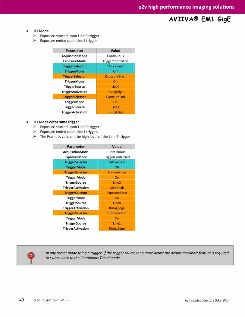
ITCMode Exposure started upon Line 0 trigger. Exposure ended upon Line1 trigger
Parameter Value
AcquisitionMode Continuous
ExposureMode TriggerControlled
TriggerSelector "All values"
TriggerMode Off
TriggerSelector ExposureStart
TriggerMode On
TriggerSource Line0
TriggerActivation RisingEdge
TriggerSelector ExposureEnd
TriggerMode On
TriggerSource Line1
TriggerActivation RisingEdge
ITCModeWithFrameTrigger Exposure started upon Line 0 trigger. Exposure ended upon Line1 trigger. The Frame is valid on the high level of the Line 2 trigger
Parameter Value
AcquisitionMode Continuous
ExposureMode TriggerControlled
TriggerSelector "All values"
TriggerMode Off
TriggerSelector FrameActive
TriggerMode On
TriggerSource Line2
TriggerActivation LevelHigh
TriggerSelector ExposureStart
TriggerMode On
TriggerSource Line0
TriggerActivation RisingEdge
TriggerSelector ExposureEnd
TriggerMode On
TriggerSource Line1
TriggerActivation RisingEdge
In any preset mode using a trigger: if the trigger source is no more active the AcquisitionAbort feature is required to switch back to the Continuous Timed mode
AVIIVA® EM1 GigE
41 e2v semiconductors SAS 2014
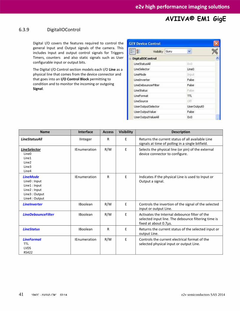
6.3.9 DigitalIOControl
Digital I/O covers the features required to control the general Input and Output signals of the camera. This includes Input and output control signals for Triggers Timers, counters and also static signals such as User configurable input or output bits. The Digital I/O Control section models each I/O Line as a physical line that comes from the device connector and that goes into an I/O Control Block permitting to condition and to monitor the incoming or outgoing Signal.
Name Interface Access Visibility Description
LineStatusAll IInteger R E Returns the current status of all available Line signals at time of polling in a single bitfield.
LineSelector Line0 Line1 Line2 Line3 Line4
IEnumeration R/W E Selects the physical line (or pin) of the external device connector to configure.
LineMode Line0 : Input Line1 : Input Line2 : Input Line3 : Output Line4 : Output
IEnumeration R E Indicates if the physical Line is used to Input or Output a signal.
LineInverter IBoolean R/W E Controls the invertion of the signal of the selected input or output Line.
LineDebounceFilter IBoolean R/W E Activates the Internal debounce filter of the selected input line. The debounce filtering time is fixed at about 0.7µs.
LineStatus IBoolean R E Returns the current status of the selected input or output Line.
LineFormat TTL LVDS RS422
IEnumeration R/W E Controls the current electrical format of the selected physical input or output Line.
AVIIVA® EM1 GigE
42 e2v semiconductors SAS 2014
Name Interface Access Visibility Description
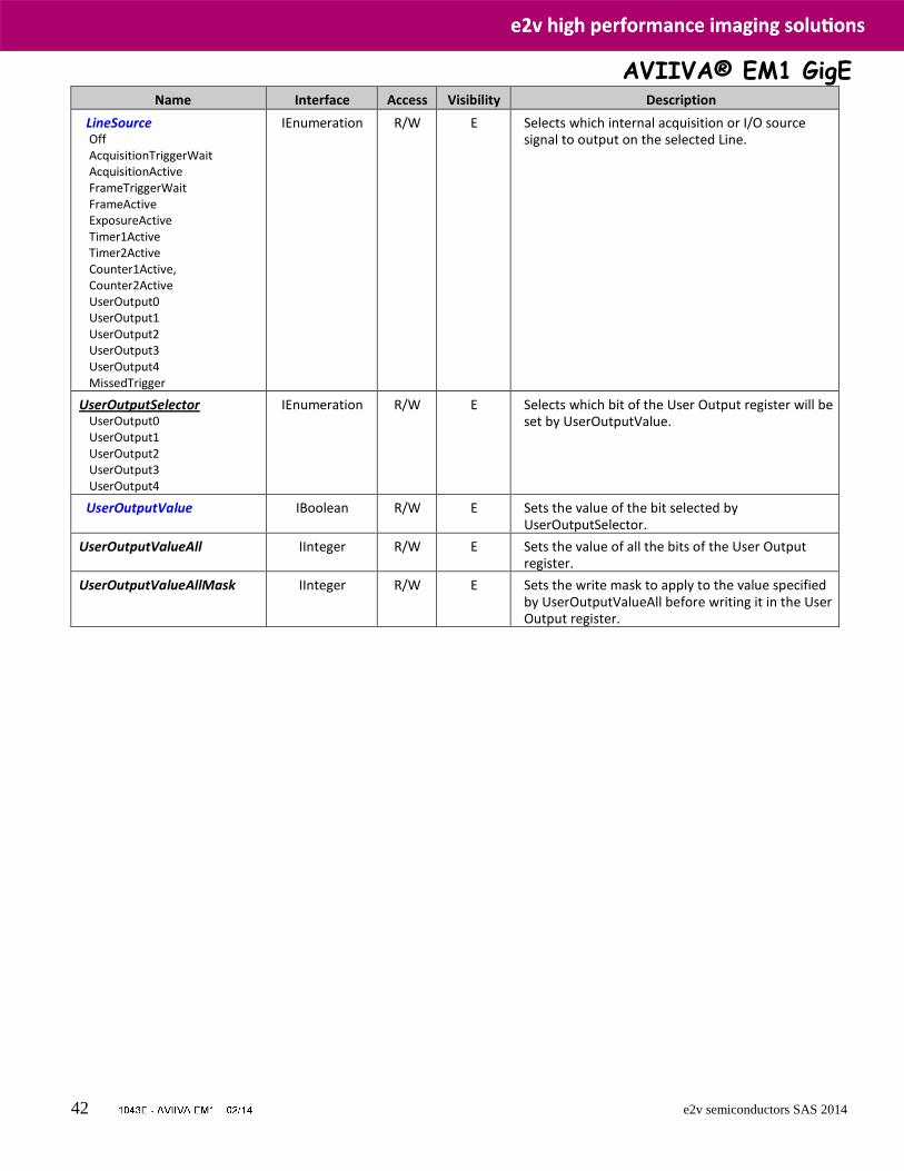
LineSource Off AcquisitionTriggerWait AcquisitionActive FrameTriggerWait FrameActive ExposureActive Timer1Active Timer2Active Counter1Active, Counter2Active UserOutput0 UserOutput1 UserOutput2 UserOutput3 UserOutput4 MissedTrigger
IEnumeration R/W E Selects which internal acquisition or I/O source signal to output on the selected Line.
UserOutputSelector UserOutput0 UserOutput1 UserOutput2 UserOutput3 UserOutput4
IEnumeration R/W E Selects which bit of the User Output register will be set by UserOutputValue.
UserOutputValue IBoolean R/W E Sets the value of the bit selected by UserOutputSelector.
UserOutputValueAll IInteger R/W E Sets the value of all the bits of the User Output register.
UserOutputValueAllMask IInteger R/W E Sets the write mask to apply to the value specified by UserOutputValueAll before writing it in the User Output register.
AVIIVA® EM1 GigE
43 e2v semiconductors SAS 2014
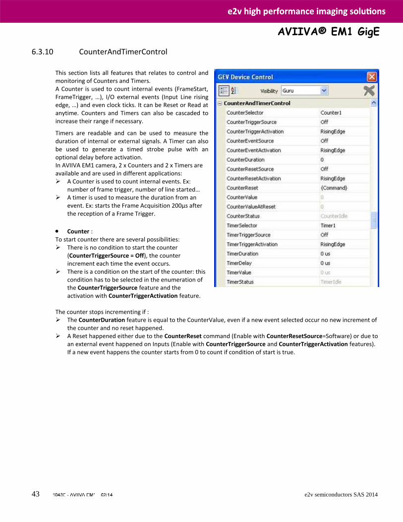
6.3.10 CounterAndTimerControl
This section lists all features that relates to control and monitoring of Counters and Timers. A Counter is used to count internal events (FrameStart, FrameTrigger, …), I/O external events (Input Line rising edge, …) and even clock ticks. It can be Reset or Read at anytime. Counters and Timers can also be cascaded to increase their range if necessary. Timers are readable and can be used to measure the duration of internal or external signals. A Timer can also be used to generate a timed strobe pulse with an optional delay before activation. In AVIIVA EM1 camera, 2 x Counters and 2 x Timers are available and are used in different applications: A Counter is used to count internal events. Ex:
number of frame trigger, number of line started… A timer is used to measure the duration from an
event. Ex: starts the Frame Acquisition 200µs after the reception of a Frame Trigger.
Counter : To start counter there are several possibilities: There is no condition to start the counter
(CounterTriggerSource = Off), the counter increment each time the event occurs.
There is a condition on the start of the counter: this condition has to be selected in the enumeration of the CounterTriggerSource feature and the activation with CounterTriggerActivation feature.
The counter stops incrementing if : The CounterDuration feature is equal to the CounterValue, even if a new event selected occur no new increment of
the counter and no reset happened. A Reset happened either due to the CounterReset command (Enable with CounterResetSource=Software) or due to
an external event happened on Inputs (Enable with CounterTriggerSource and CounterTriggerActivation features). If a new event happens the counter starts from 0 to count if condition of start is true.

AVIIVA® EM1 GigE
44 e2v semiconductors SAS 2014
Name Interface Access Visibility Description
CounterSelector Counter1 Counter2
IEnumeration R/W E Selects which counter to configure.
CounterTriggerSource IEnumeration R/W E Selects the source to start the counter.
CounterTriggerActivation IEnumeration R/W E Selects the activation mode of the trigger to start the counter.
CounterEventSource Off AcquisitionStart AcquisitionEnd AcquisitionTrigger FrameStart FrameEnd FrameTrigger ExposureStart ExposureEnd Line0 Line1 Line2 Counter1End Counter2End Timer1End Timer2End TimeStampTick MissedTrigger
IEnumeration R/W E Select the events that will be the source to increment the counter.
CounterEventActivation RisingEdge FallingEdge AnyEdge LevelHigh LevelLow
IEnumeration R/W E Selects the Activation mode Event Source signal.
CounterDuration IInteger R/W E Sets the duration (or number of events) before the CounterEnd event is generated.
CounterResetSource Off Software Line0 Line1 Line2
IEnumeration R/W E Selects the signals that will be the source to reset the counter.
CounterResetActivation RisingEdge FallingEdge AnyEdge LevelHigh LevelLow
IEnumeration R/W E Selects the Activation mode counter Reset Source signal.
CounterReset ICommand (R)/W E Does a software reset of the selected counter.
CounterValue IInteger R/W E Reads or writes the current value of the selected counter.
Name Interface Access Visibility Description
CounterValueAtReset IInteger R E Reads the value of the selected counter when it was reset by a trigger or by an explicit CounterReset cmd.
CounterStatus IEnumeration R E Returns the current state of the counter.

AVIIVA® EM1 GigE
45 e2v semiconductors SAS 2014
CounterIdle CounterTriggerWait CounterActive CounterCompleted CounterOverflow
Timer : The timer starts with the event occured on the selected list of TimerTriggerSource feature (type of activation selected by TimerTriggerActivation feature). The adjustment of the timer is performed with TimerDuration (time before the generation of the event TimerEnd) and a TimerDelay (Delay before starting the duration value) features. If it happens a new event (which is selected to start the timer) timer reset before restart the duration.
Name Interface Access Visibility Description
TimerSelector Timer1 Timer2
IEnumeration R/W E Selects which Timer to configure.
TimerTriggerSource Off AcquisitionStart AcquisitionEnd AcquisitionTrigger FrameStart FrameEnd FrameTrigger ExposureStart ExposureEnd Line0 Line1 Line2 Counter1End Counter2End Timer1End Timer2End TimeStampTick MissedTrigger
IEnumeration R/W E Selects the source of the trigger to start the Timer.
TimerTriggerActivation RisingEdge FallingEdge AnyEdge LevelHigh LevelLow
IEnumeration R/W E Selects the activation mode of the trigger to start the Timer.
TimerDuration IFloat R/W E Sets the duration (in µs) of the Timer pulse.
TimerDelay IFloat R/W E Sets the duration (in µs) of the delay to apply at the reception of a trigger before to start the Timer.
Name Interface Access Visibility Description
TimerValue IFloat R/W E Reads or writes the current value (in µs) of the selected Timer.
TimerStatus TimerIdle TimerTriggerWait TimerActive
IEnumeration R E Returns the current state of the Timer.

AVIIVA® EM1 GigE
46 e2v semiconductors SAS 2014
TimerCompleted
AVIIVA® EM1 GigE
47 e2v semiconductors SAS 2014
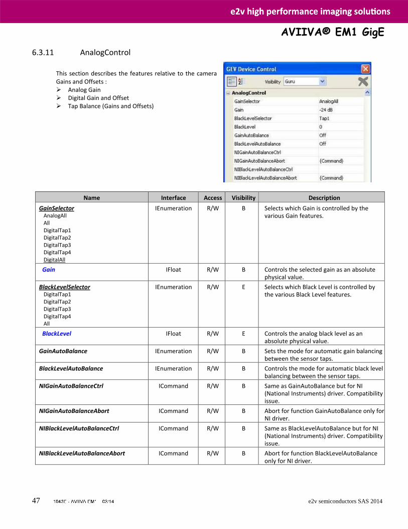
6.3.11 AnalogControl
This section describes the features relative to the camera Gains and Offsets : Analog Gain Digital Gain and Offset Tap Balance (Gains and Offsets)
Name Interface Access Visibility Description
GainSelector AnalogAll All DigitalTap1 DigitalTap2 DigitalTap3 DigitalTap4 DigitalAll
IEnumeration R/W B Selects which Gain is controlled by the various Gain features.
Gain IFloat R/W B Controls the selected gain as an absolute physical value.
BlackLevelSelector DigitalTap1 DigitalTap2 DigitalTap3 DigitalTap4 All
IEnumeration R/W E Selects which Black Level is controlled by the various Black Level features.
BlackLevel IFloat R/W E Controls the analog black level as an absolute physical value.
GainAutoBalance IEnumeration R/W B Sets the mode for automatic gain balancing between the sensor taps.
BlackLevelAutoBalance IEnumeration R/W B Controls the mode for automatic black level balancing between the sensor taps.
NIGainAutoBalanceCtrl ICommand R/W B Same as GainAutoBalance but for NI (National Instruments) driver. Compatibility issue.
NIGainAutoBalanceAbort ICommand R/W B Abort for function GainAutoBalance only for NI driver.
NIBlackLevelAutoBalanceCtrl ICommand R/W B Same as BlackLevelAutoBalance but for NI (National Instruments) driver. Compatibility issue.
NIBlackLevelAutoBalanceAbort ICommand R/W B Abort for function BlackLevelAutoBalance only for NI driver.
AVIIVA® EM1 GigE
48 e2v semiconductors SAS 2014
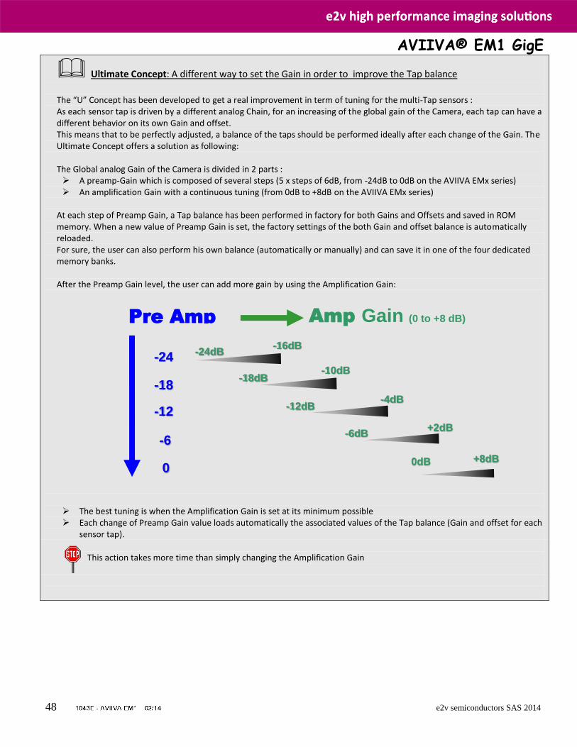
Ultimate Concept: A different way to set the Gain in order to improve the Tap balance
The “U” Concept has been developed to get a real improvement in term of tuning for the multi-Tap sensors : As each sensor tap is driven by a different analog Chain, for an increasing of the global gain of the Camera, each tap can have a different behavior on its own Gain and offset. This means that to be perfectly adjusted, a balance of the taps should be performed ideally after each change of the Gain. The Ultimate Concept offers a solution as following: The Global analog Gain of the Camera is divided in 2 parts : A preamp-Gain which is composed of several steps (5 x steps of 6dB, from -24dB to 0dB on the AVIIVA EMx series) An amplification Gain with a continuous tuning (from 0dB to +8dB on the AVIIVA EMx series)
At each step of Preamp Gain, a Tap balance has been performed in factory for both Gains and Offsets and saved in ROM memory. When a new value of Preamp Gain is set, the factory settings of the both Gain and offset balance is automatically reloaded. For sure, the user can also perform his own balance (automatically or manually) and can save it in one of the four dedicated memory banks. After the Preamp Gain level, the user can add more gain by using the Amplification Gain:
The best tuning is when the Amplification Gain is set at its minimum possible Each change of Preamp Gain value loads automatically the associated values of the Tap balance (Gain and offset for each
sensor tap).
This action takes more time than simply changing the Amplification Gain
Pre Amp
Gain
-6
-12
-18
-24
Amp Gain (0 to +8 dB)
-24dB
-16dB
-18dB -10dB
-12dB -4dB
-6dB +2dB
0 +8dB 0dB
AVIIVA® EM1 GigE
49 e2v semiconductors SAS 2014
OUT CCD X
Preamp
Gain
+ X
Tap Balance
Offset Gain
X
Amp
Gain
+ X
FFC
Offset Gain
X
FFC
Adjust
+ X
LUT or
Contrast Exp.
Offset Gain
Action on whole line
Action per pixel
Action per sensor’s Tap
The Global Chain of Gain is described as following :
6.3.11.1 Analog Gain
Preamp Gain : (GainAbs with GainSelector= AnalogAll) The Preamp Gain is set by step of 6dB :
0 : (-24dB)
1 : (-18dB)
2 : (-12dB)
3 : (-6dB)
4 : (0dB)
Gain: (GainAbs with GainSelector= All)
Value from 0 to 6193 corresponding to a Gain range of 0dB to +8dB calculated as following : Gain(dB) = 20.log(1+ Gain/4096).
6.3.11.2 Digital Gain & Offset (Contrast Expansion)
Digital Gain (GainAbs with GainSelector=DigitalAll). Integer value from 0 to 255. The corresponding Gain is calculated as 20log(1+val/64) in dB
Digital Offset (BlackLevelRaw with BlackLevelSelector=All) Value from –4096 to +4095 in LSB
The Contrast Expansion (both Digital Gain & Offset) will be automatically disabled if the LUT is enabled..
AVIIVA® EM1 GigE
50 e2v semiconductors SAS 2014
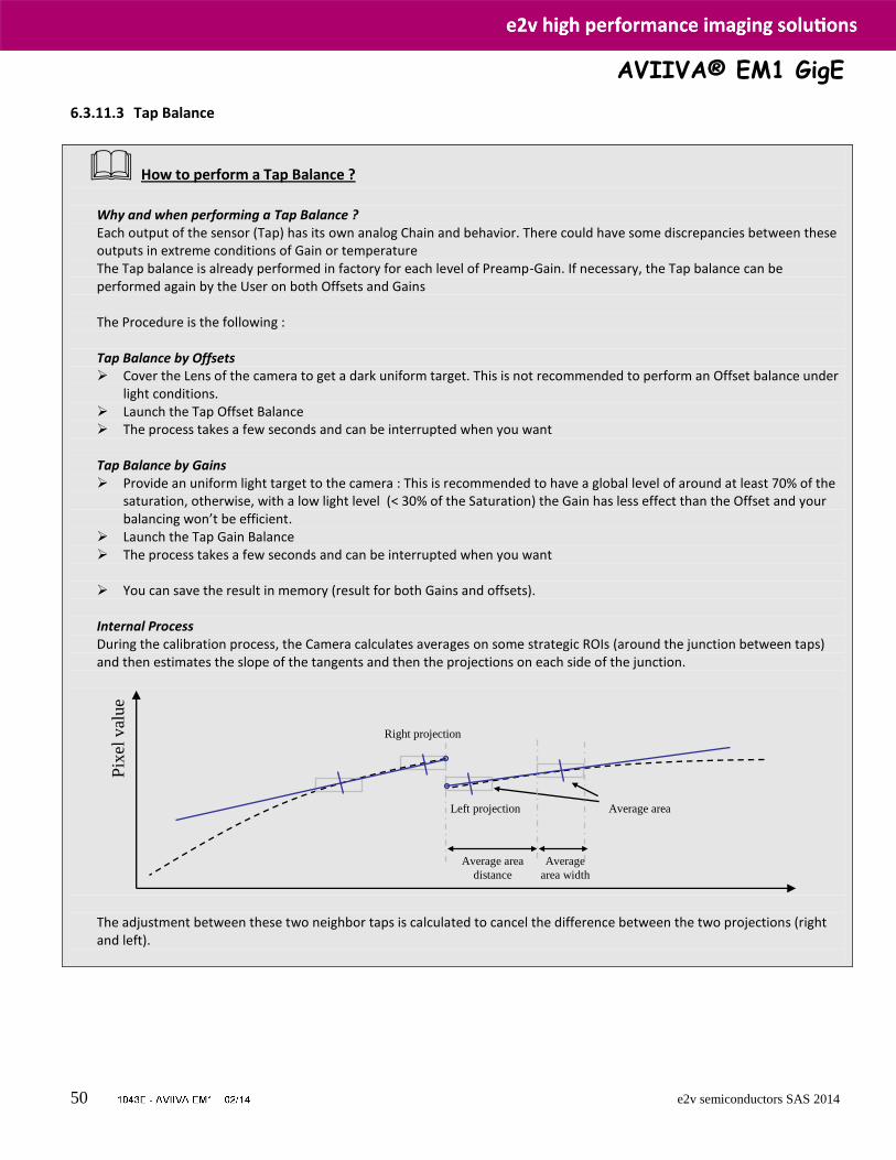
6.3.11.3 Tap Balance
How to perform a Tap Balance ?
Why and when performing a Tap Balance ? Each output of the sensor (Tap) has its own analog Chain and behavior. There could have some discrepancies between these outputs in extreme conditions of Gain or temperature The Tap balance is already performed in factory for each level of Preamp-Gain. If necessary, the Tap balance can be performed again by the User on both Offsets and Gains The Procedure is the following : Tap Balance by Offsets Cover the Lens of the camera to get a dark uniform target. This is not recommended to perform an Offset balance under
light conditions. Launch the Tap Offset Balance The process takes a few seconds and can be interrupted when you want Tap Balance by Gains Provide an uniform light target to the camera : This is recommended to have a global level of around at least 70% of the
saturation, otherwise, with a low light level (< 30% of the Saturation) the Gain has less effect than the Offset and your balancing won’t be efficient.
Launch the Tap Gain Balance The process takes a few seconds and can be interrupted when you want
You can save the result in memory (result for both Gains and offsets).
Internal Process During the calibration process, the Camera calculates averages on some strategic ROIs (around the junction between taps) and then estimates the slope of the tangents and then the projections on each side of the junction.
The adjustment between these two neighbor taps is calculated to cancel the difference between the two projections (right and left).
Right projection
Left projection Average area
Pix
el v
alue
Average area
distance
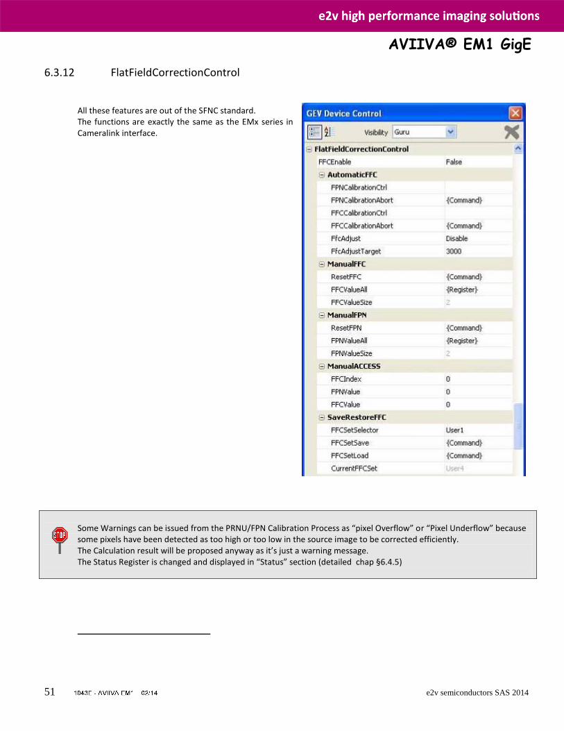
Average
area width
AVIIVA® EM1 GigE
51 e2v semiconductors SAS 2014
6.3.12 FlatFieldCorrectionControl All these features are out of the SFNC standard. The functions are exactly the same as the EMx series in Cameralink interface.
Some Warnings can be issued from the PRNU/FPN Calibration Process as “pixel Overflow” or “Pixel Underflow” because some pixels have been detected as too high or too low in the source image to be corrected efficiently. The Calculation result will be proposed anyway as it’s just a warning message. The Status Register is changed and displayed in “Status” section (detailed chap §6.4.5)
AVIIVA® EM1 GigE
52 e2v semiconductors SAS 2014
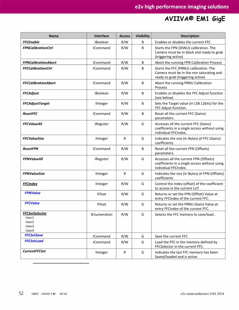
Name Interface Access Visibility Description
FFCEnable IBoolean R/W B Enables or disables the current FFC
FPNCalibrationCtrl ICommand R/W B Starts the FPN (DSNU) calibration. The Camera must be in black and ready to grab (triggering active)
FPNCalibrationAbort ICommand R/W B Abort the running FPN Calibration Process
FFCCalibrationCtrl ICommand R/W B Starts the FFC (PRNU) calibration. The Camera must be in the non saturating and ready to grab (triggering active)
FFCCalibrationAbort ICommand R/W B Abort the running PRNU Calibration Process
FFCAdjust IBoolean R/W B Enables or disables the FFC Adjust function (see below)
FFCAdjustTarget IInteger R/W B Sets the Target value (in LSB 12bits) for the FFC Adjust function.
ResetFFC ICommand R/W B Reset all the current FFC (Gains) parameters.
FFCValueAll IRegister R/W G Accesses all the current FFC (Gains) coefficients in a single access without using individual FFCIndex.
FFCValueSize IInteger R G Indicates the size (in Bytes) of FFC (Gains) coefficients
ResetFPN ICommand R/W B Reset all the current FPN (Offsets) parameters.
FPNValueAll IRegister R/W G Accesses all the current FPN (Offsets) coefficients in a single access without using individual FFCIndex.
FPNValueSize IInteger R G Indicates the size (in Bytes) of FPN (Offsets) coefficients
FFCIndex IInteger R/W G Control the index (offset) of the coefficient to access in the current LUT
FPNValue IFloat R/W G Returns or set the FPN (Offset) Value at entry FFCIndex of the current FFC.
FFCValue IFloat R/W G Returns or set the PRNU (Gain) Value at entry FFCIndex of the current FFC.
FFCSetSelector User1 User2 User3 User4
IEnumeration R/W G Selects the FFC memory to save/load .
FFCSetSave ICommand R/W G Save the current FFC FFCSetLoad ICommand R/W G Load the FFC in the memory defined by
FFCSelector in the current FFC. CurrentFFCSet IInteger R G Indicates the last FFC memory has been
Saved/loaded and is active
AVIIVA® EM1 GigE
53 e2v semiconductors SAS 2014
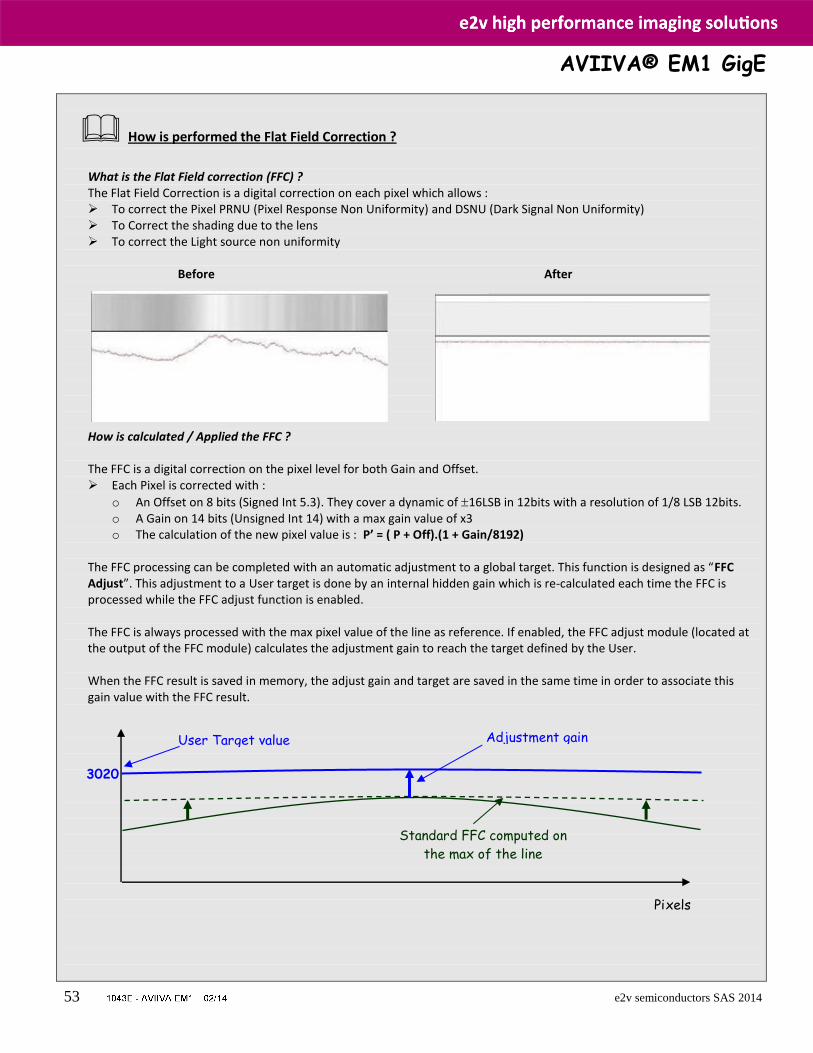
How is performed the Flat Field Correction ?
What is the Flat Field correction (FFC) ? The Flat Field Correction is a digital correction on each pixel which allows : To correct the Pixel PRNU (Pixel Response Non Uniformity) and DSNU (Dark Signal Non Uniformity) To Correct the shading due to the lens To correct the Light source non uniformity
Before After
How is calculated / Applied the FFC ? The FFC is a digital correction on the pixel level for both Gain and Offset. Each Pixel is corrected with :
o An Offset on 8 bits (Signed Int 5.3). They cover a dynamic of 16LSB in 12bits with a resolution of 1/8 LSB 12bits. o A Gain on 14 bits (Unsigned Int 14) with a max gain value of x3 o The calculation of the new pixel value is : P’ = ( P + Off).(1 + Gain/8192)
The FFC processing can be completed with an automatic adjustment to a global target. This function is designed as “FFC Adjust”. This adjustment to a User target is done by an internal hidden gain which is re-calculated each time the FFC is processed while the FFC adjust function is enabled. The FFC is always processed with the max pixel value of the line as reference. If enabled, the FFC adjust module (located at the output of the FFC module) calculates the adjustment gain to reach the target defined by the User. When the FFC result is saved in memory, the adjust gain and target are saved in the same time in order to associate this gain value with the FFC result.
Pixels
3020
User Target value
Standard FFC computed on
the max of the line
Adjustment gain
AVIIVA® EM1 GigE
54 e2v semiconductors SAS 2014
How to perform the Flat Field Correction ? FPN/DSNU Calibration Cover the lens Launch the FPN Calibration : Grab and calculation is performed in few seconds
PRNU Calibration The User must propose a white/gray uniform target to the Camera (not a fixed paper). The Gain/Light conditions must give a non saturated image in any Line. The Camera must be set in the final conditions of Light/ Gain and in the final position in the System. I f required, set a user target for the FFC adjust and enable it. White uniform (moving) target Launch the FFC Enable the FFC You can save the FFC result (both FPN+PRNU in the same time) in one of the 4 x FFC User Banks. The user target and Gain are saved with the associated FFC in the same memory. Advices
The AVIIVA EM1 Cameras have 4 x FFC Banks to save 4 x different FFC calibrations. You can use this feature if your system needs some different conditions of lightning and/or Gain because of the inspection of different objects : You can perform one FFC per condition of Gain/setting of the Camera ( 4 Max) and recall one of the four global settings (Camera Configuration + FFC + Line Balance) when required.
FFC Adjust : A good usage. When there are several Cameras to set up in a system on a single line, the most difficult is to have a uniform lightning whole along the line. If each Camera performs its own Flat field correction, relative to the max of each pixel line, the result will be a succession of Camera lines at different levels. => The FFC Adjust function allows to set the same target value for all the Cameras in the system and then to get a perfect uniform line whole along the system with a precision of 1 LSB to the Target. The reasonable value for the User Target is not more than around 20% of the max value of the line.
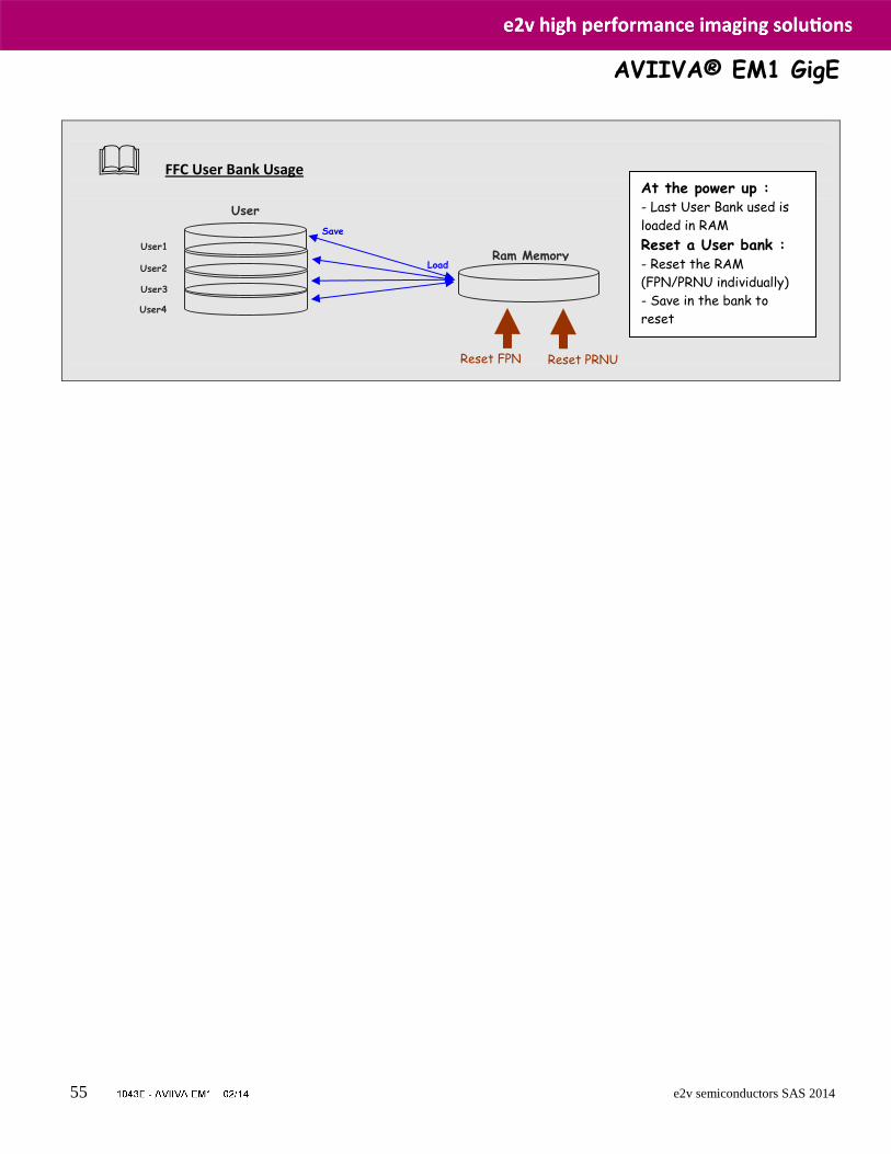
AVIIVA® EM1 GigE
55 e2v semiconductors SAS 2014
FFC User Bank Usage
User1
User2
User3
User4
User
banks
Ram Memory
Save
Load
Reset FPN Reset PRNU
At the power up : - Last User Bank used is
loaded in RAM
Reset a User bank : - Reset the RAM
(FPN/PRNU individually)
- Save in the bank to
reset
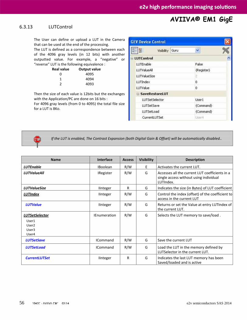
AVIIVA® EM1 GigE
56 e2v semiconductors SAS 2014
6.3.13 LUTControl
The User can define or upload a LUT in the Camera that can be used at the end of the processing. The LUT is defined as a correspondence between each of the 4096 gray levels (in 12 bits) with another outputted value. For example, a “negative” or “reverse” LUT is the following equivalence : Real value Output value 0 4095 1 4094 2 4093 Then the size of each value is 12bits but the exchanges with the Application/PC are done on 16 bits : For 4096 gray levels (from 0 to 4095) the total file size for a LUT is 8Ko.
If the LUT is enabled, The Contrast Expansion (both Digital Gain & Offset) will be automatically disabled..
Name Interface Access Visibility Description
LUTEnable IBoolean R/W E Activates the current LUT. LUTValueAll IRegister R/W G Accesses all the current LUT coefficients in a
single access without using individual LUTIndex.
LUTValueSize IInteger R G Indicates the size (in Bytes) of LUT coefficient LUTIndex IInteger R/W G Control the index (offset) of the coefficient to
access in the current LUT
LUTValue IInteger R/W G Returns or set the Value at entry LUTIndex of the current LUT.
LUTSetSelector
User1 User2 User3 User4
IEnumeration R/W G Selects the LUT memory to save/load .
LUTSetSave ICommand R/W G Save the current LUT
LUTSetLoad ICommand R/W G Load the LUT in the memory defined by LUTSelector in the current LUT.
CurrentLUTSet IInteger R G Indicates the last LUT memory has been Saved/loaded and is active
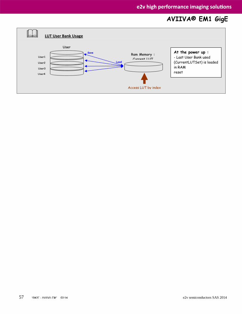
AVIIVA® EM1 GigE
57 e2v semiconductors SAS 2014
LUT User Bank Usage
User1
User2
User3
User4
User
banks Ram Memory :
Current LUT
Save
Load
Access LUT by index
At the power up : - Last User Bank used
(CurrentLUTSet) is loaded
in RAM
reset

AVIIVA® EM1 GigE
58 e2v semiconductors SAS 2014
6.3.14 Statistics and Line Profile
This function allows the User to get some statistics on a pre-defined ROI. On request, the Camera acquires and then calculates some key values as the min, the max, the average or the standard deviation in this Region of Interest. The grab and calculation command and also the collection of the results is not performed in real time as it is done through the register access. The Calculated values are detailed as following :
o Pixel average Value (PixelROIMean) : Average gray level
value calculated on whole Region of interest : Unsigned format value : U12.4
o Pixel Standard deviation (PixelROIStandardDeviation) : standard deviation of all the pixel gray level values of Region of interest : Unsigned format value : U12.4
o Pixel Min value (PixelROIMin) : Minimum gray level pixel
value on the whole region of interest.: Unsigned format value : U12.4
o Pixel Max Value (PixelROIMax) : Maximum gray level pixel value on the whole region of interest: Unsigned format
value : U12.4
Name Interface Access Visibility Description
LineAverageProfileMeasurement ICommand R/W E Activates the current LUT.
LineAverageProfileMeasurementAbort ICommand R/W G Accesses all the current LUT coefficients in a single access without using individual LUTIndex.
PixelAccessLineNumber
Line1 Line256 Line512 Line1024
IEnumeration R/W G Select the number of lines to accumulate for the Line Profile processing : 1, 256, 512 or 1024 lines.
PixelROIStart IInteger R G Define the start of the ROI for the line processing.
PixelROIWidth IInteger R G Define the size of the ROI.
PixelROIMean IFloat R G Indicates the Average value on the ROI in LSB 12bits
PixelROIStandardDeviation IFloat R G Indicates the Standard deviation on the ROI in LSB 12bits
PixelROIMin IInteger R G Indicates the Minimum Value on the ROI in LSB 12bits
PixelROIMax IInteger R G Indicates the Maximum Value on the ROI in LSB 12bits
Name Interface Access Visibility Description
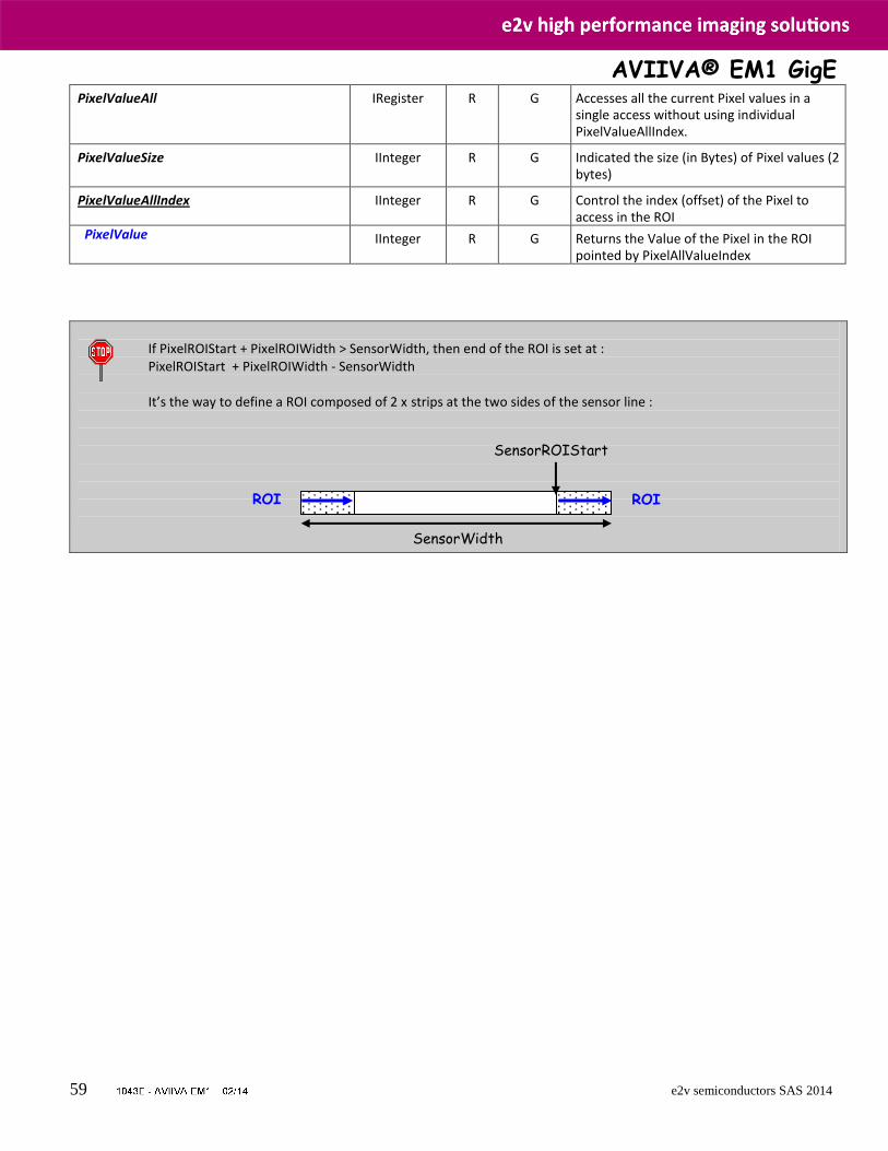
AVIIVA® EM1 GigE
59 e2v semiconductors SAS 2014
PixelValueAll IRegister R G Accesses all the current Pixel values in a single access without using individual PixelValueAllIndex.
PixelValueSize IInteger R G Indicated the size (in Bytes) of Pixel values (2 bytes)
PixelValueAllIndex IInteger R G Control the index (offset) of the Pixel to access in the ROI
PixelValue IInteger R G Returns the Value of the Pixel in the ROI pointed by PixelAllValueIndex
If PixelROIStart + PixelROIWidth > SensorWidth, then end of the ROI is set at : PixelROIStart + PixelROIWidth - SensorWidth It’s the way to define a ROI composed of 2 x strips at the two sides of the sensor line :
SensorWidth
SensorROIStart
ROI ROI
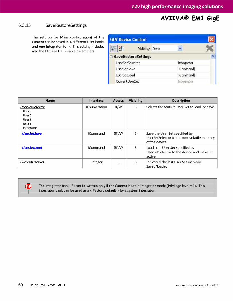
AVIIVA® EM1 GigE
60 e2v semiconductors SAS 2014
6.3.15 SaveRestoreSettings
The settings (or Main configuration) of the Camera can be saved in 4 different User banks and one Integrator bank. This setting includes also the FFC and LUT enable parameters
Name Interface Access Visibility Description
UserSetSelector User1 User2 User3 User4 Integrator
IEnumeration R/W B Selects the feature User Set to load or save.
UserSetSave ICommand (R)/W B Save the User Set specified by UserSetSelector to the non-volatile memory of the device.
UserSetLoad ICommand (R)/W B Loads the User Set specified by UserSetSelector to the device and makes it active.
CurrentUserSet IInteger R B Indicated the last User Set memory Saved/loaded
The integrator bank (5) can be written only if the Camera is set in integrator mode (Privilege level = 1). This integrator bank can be used as a « Factory default » by a system integrator.
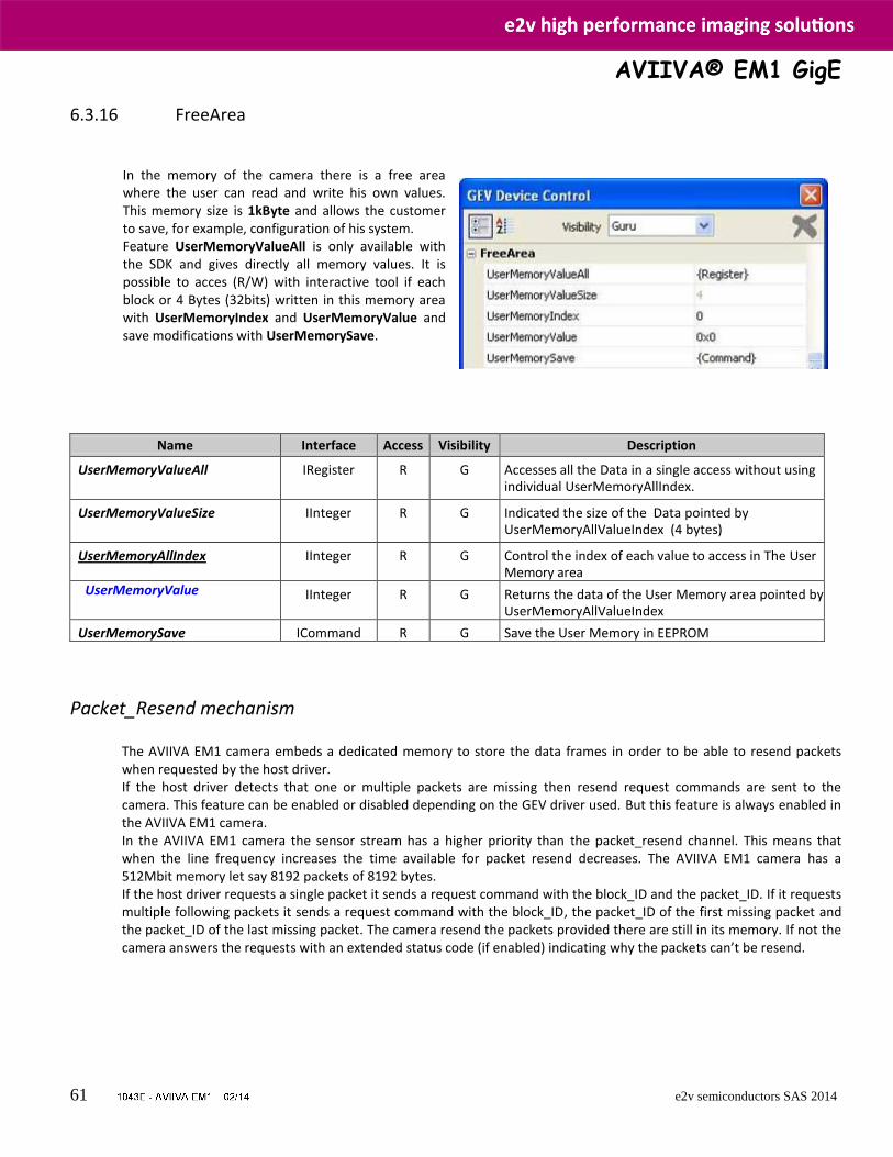
AVIIVA® EM1 GigE
61 e2v semiconductors SAS 2014
6.3.16 FreeArea In the memory of the camera there is a free area where the user can read and write his own values. This memory size is 1kByte and allows the customer to save, for example, configuration of his system. Feature UserMemoryValueAll is only available with the SDK and gives directly all memory values. It is possible to acces (R/W) with interactive tool if each block or 4 Bytes (32bits) written in this memory area with UserMemoryIndex and UserMemoryValue and save modifications with UserMemorySave.
Name Interface Access Visibility Description
UserMemoryValueAll IRegister R G Accesses all the Data in a single access without using individual UserMemoryAllIndex.
UserMemoryValueSize IInteger R G Indicated the size of the Data pointed by UserMemoryAllValueIndex (4 bytes)
UserMemoryAllIndex IInteger R G Control the index of each value to access in The User Memory area
UserMemoryValue IInteger R G Returns the data of the User Memory area pointed by UserMemoryAllValueIndex
UserMemorySave ICommand R G Save the User Memory in EEPROM
Packet_Resend mechanism
The AVIIVA EM1 camera embeds a dedicated memory to store the data frames in order to be able to resend packets when requested by the host driver. If the host driver detects that one or multiple packets are missing then resend request commands are sent to the camera. This feature can be enabled or disabled depending on the GEV driver used. But this feature is always enabled in the AVIIVA EM1 camera. In the AVIIVA EM1 camera the sensor stream has a higher priority than the packet_resend channel. This means that when the line frequency increases the time available for packet resend decreases. The AVIIVA EM1 camera has a 512Mbit memory let say 8192 packets of 8192 bytes. If the host driver requests a single packet it sends a request command with the block_ID and the packet_ID. If it requests multiple following packets it sends a request command with the block_ID, the packet_ID of the first missing packet and the packet_ID of the last missing packet. The camera resend the packets provided there are still in its memory. If not the camera answers the requests with an extended status code (if enabled) indicating why the packets can’t be resend.
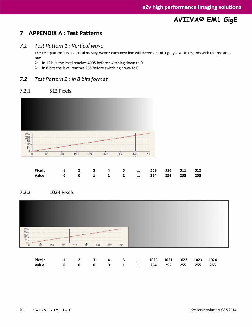
AVIIVA® EM1 GigE
62 e2v semiconductors SAS 2014
7 APPENDIX A : Test Patterns
7.1 Test Pattern 1 : Vertical wave The Test pattern 1 is a vertical moving wave : each new line will increment of 1 gray level in regards with the previous one. In 12 bits the level reaches 4095 before switching down to 0 In 8 bits the level reaches 255 before switching down to 0
7.2 Test Pattern 2 : In 8 bits format
7.2.1 512 Pixels
Pixel : 1 2 3 4 5 … 509 510 511 512 Value : 0 0 1 1 2 … 254 254 255 255
7.2.2 1024 Pixels
Pixel : 1 2 3 4 5 … 1020 1021 1022 1023 1024 Value : 0 0 0 0 1 … 254 255 255 255 255
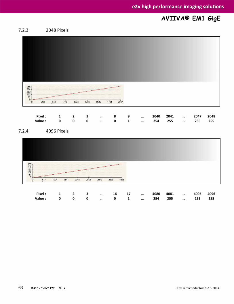
AVIIVA® EM1 GigE
63 e2v semiconductors SAS 2014
7.2.3 2048 Pixels Pixel : 1 2 3 … 8 9 … 2040 2041 … 2047 2048 Value : 0 0 0 … 0 1 … 254 255 … 255 255
7.2.4 4096 Pixels Pixel : 1 2 3 … 16 17 … 4080 4081 … 4095 4096 Value : 0 0 0 … 0 1 … 254 255 … 255 255
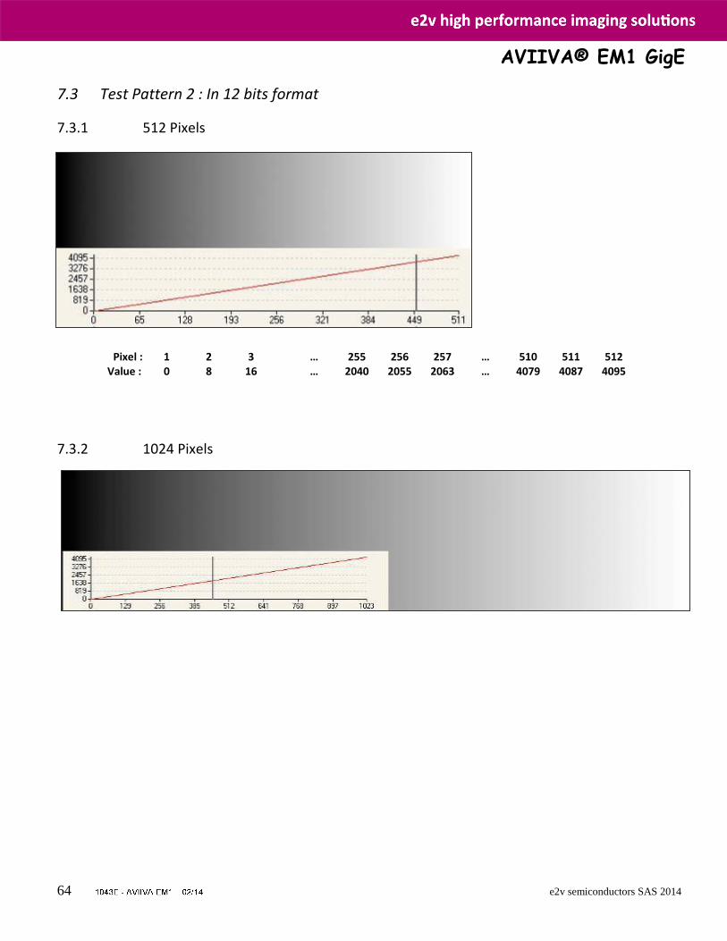
AVIIVA® EM1 GigE
64 e2v semiconductors SAS 2014
7.3 Test Pattern 2 : In 12 bits format
7.3.1 512 Pixels
Pixel : 1 2 3 … 255 256 257 … 510 511 512 Value : 0 8 16 … 2040 2055 2063 … 4079 4087 4095
7.3.2 1024 Pixels
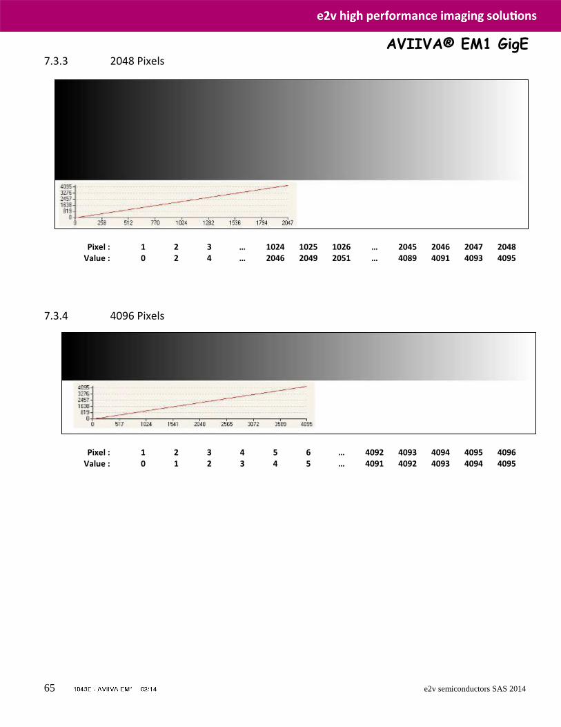
AVIIVA® EM1 GigE
65 e2v semiconductors SAS 2014
7.3.3 2048 Pixels
Pixel : 1 2 3 … 1024 1025 1026 … 2045 2046 2047 2048 Value : 0 2 4 … 2046 2049 2051 … 4089 4091 4093 4095
7.3.4 4096 Pixels
Pixel : 1 2 3 4 5 6 … 4092 4093 4094 4095 4096 Value : 0 1 2 3 4 5 … 4091 4092 4093 4094 4095
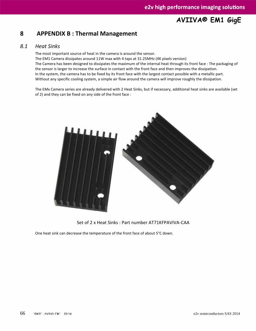
AVIIVA® EM1 GigE
66 e2v semiconductors SAS 2014
8 APPENDIX B : Thermal Management
8.1 Heat Sinks The most important source of heat in the camera is around the sensor. The EM1 Camera dissipates around 11W max with 4 taps at 31.25MHz (4K pixels version) The Camera has been designed to dissipates the maximum of the internal heat through its front face : The packaging of the sensor is larger to increase the surface in contact with the front face and then improves the dissipation. In the system, the camera has to be fixed by its front face with the largest contact possible with a metallic part. Without any specific cooling system, a simple air flow around the camera will improve roughly the dissipation. The EMx Camera series are already delivered with 2 Heat Sinks, but if necessary, additional heat sinks are available (set of 2) and they can be fixed on any side of the front face :
Set of 2 x Heat Sinks : Part number AT71KFPAVIVA-CAA
One heat sink can decrease the temperature of the front face of about 5°C down.
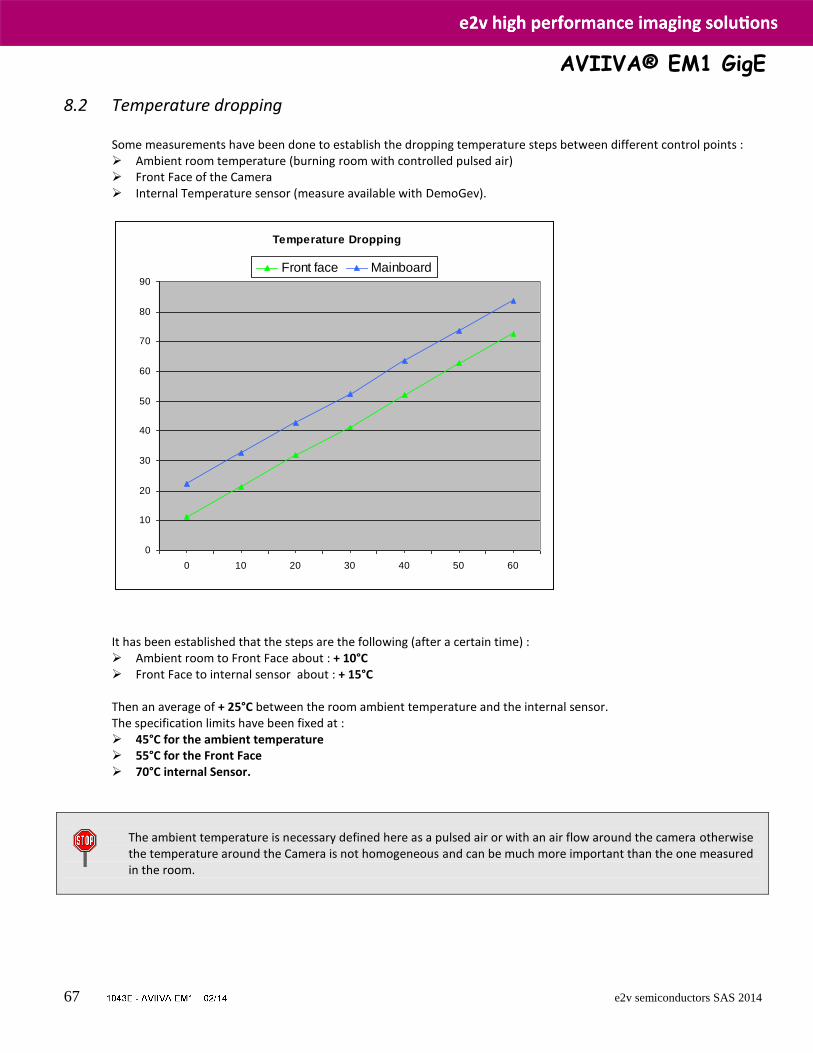
AVIIVA® EM1 GigE
67 e2v semiconductors SAS 2014
8.2 Temperature dropping Some measurements have been done to establish the dropping temperature steps between different control points : Ambient room temperature (burning room with controlled pulsed air) Front Face of the Camera Internal Temperature sensor (measure available with DemoGev).
It has been established that the steps are the following (after a certain time) : Ambient room to Front Face about : + 10°C Front Face to internal sensor about : + 15°C
Then an average of + 25°C between the room ambient temperature and the internal sensor. The specification limits have been fixed at : 45°C for the ambient temperature 55°C for the Front Face 70°C internal Sensor.
The ambient temperature is necessary defined here as a pulsed air or with an air flow around the camera otherwise the temperature around the Camera is not homogeneous and can be much more important than the one measured in the room.
Temperature Dropping
0
10
20
30
40
50
60
70
80
90
0 10 20 30 40 50 60
Front face Mainboard
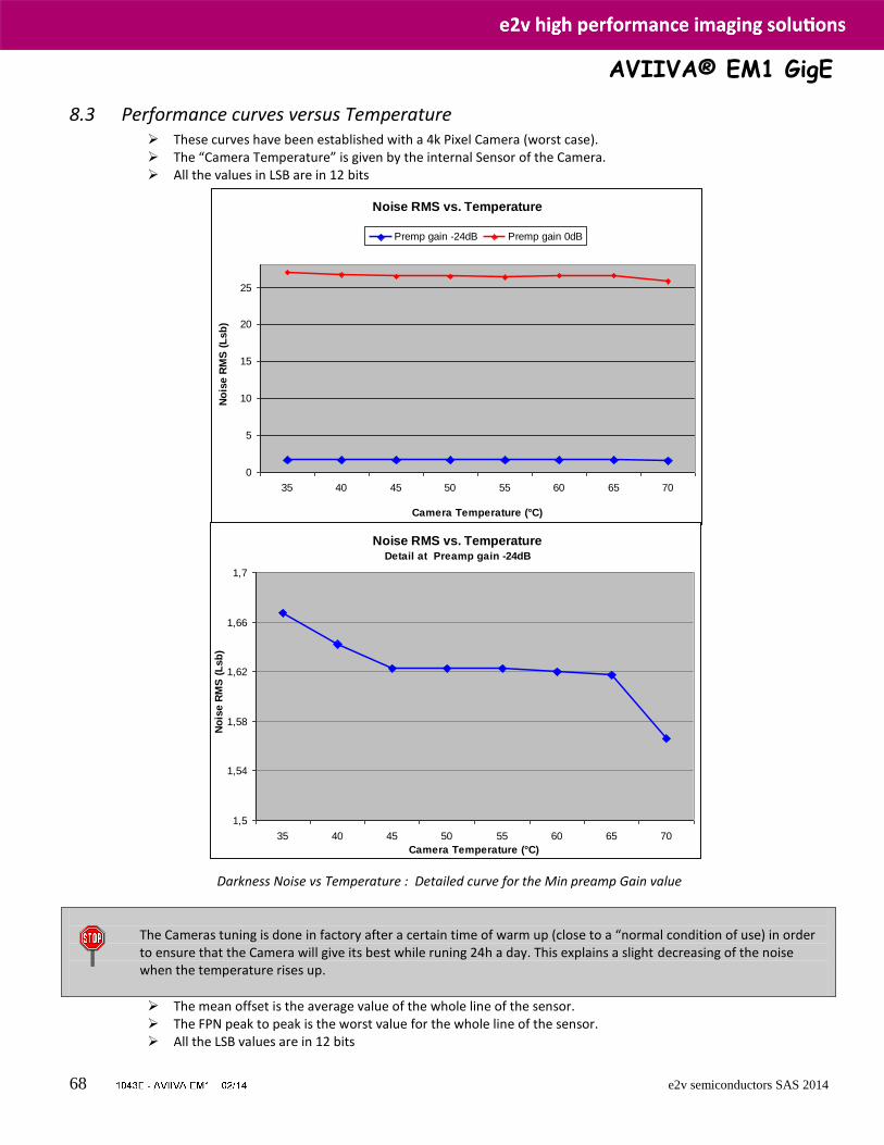
AVIIVA® EM1 GigE
68 e2v semiconductors SAS 2014
8.3 Performance curves versus Temperature These curves have been established with a 4k Pixel Camera (worst case). The “Camera Temperature” is given by the internal Sensor of the Camera. All the values in LSB are in 12 bits
Darkness Noise vs Temperature : For both Min an Max preamp Gain values
Darkness Noise vs Temperature : Detailed curve for the Min preamp Gain value
The Cameras tuning is done in factory after a certain time of warm up (close to a “normal condition of use) in order to ensure that the Camera will give its best while runing 24h a day. This explains a slight decreasing of the noise when the temperature rises up.
The mean offset is the average value of the whole line of the sensor. The FPN peak to peak is the worst value for the whole line of the sensor. All the LSB values are in 12 bits
Noise RMS vs. Temperature
0
5
10
15
20
25
35 40 45 50 55 60 65 70
Camera Temperature (°C)
No
ise R
MS
(L
sb
)
Premp gain -24dB Premp gain 0dB
Noise RMS vs. Temperature Detail at Preamp gain -24dB
1,5
1,54
1,58
1,62
1,66
1,7
35 40 45 50 55 60 65 70
Camera Temperature (°C)
No
ise R
MS
(L
sb
)
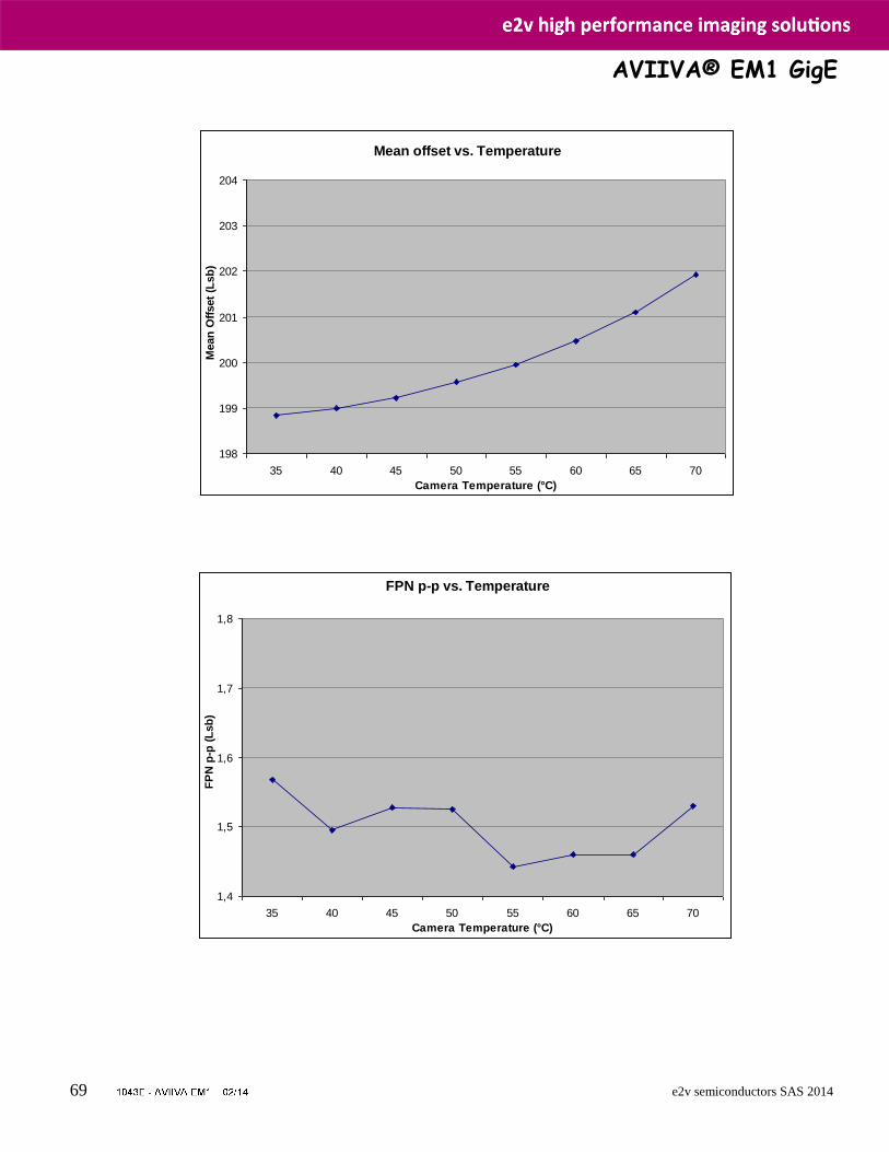
AVIIVA® EM1 GigE
69 e2v semiconductors SAS 2014
Average Offset vs Temperature : At min preamp Gain value (-24dB)
FPN peak-peak vs Temperature : At min preamp Gain value (-24dB)
Mean offset vs. Temperature
198
199
200
201
202
203
204
35 40 45 50 55 60 65 70
Camera Temperature (°C)
Mean
Off
set
(Lsb
)
FPN p-p vs. Temperature
1,4
1,5
1,6
1,7
1,8
35 40 45 50 55 60 65 70
Camera Temperature (°C)
FP
N p
-p (
Lsb
)
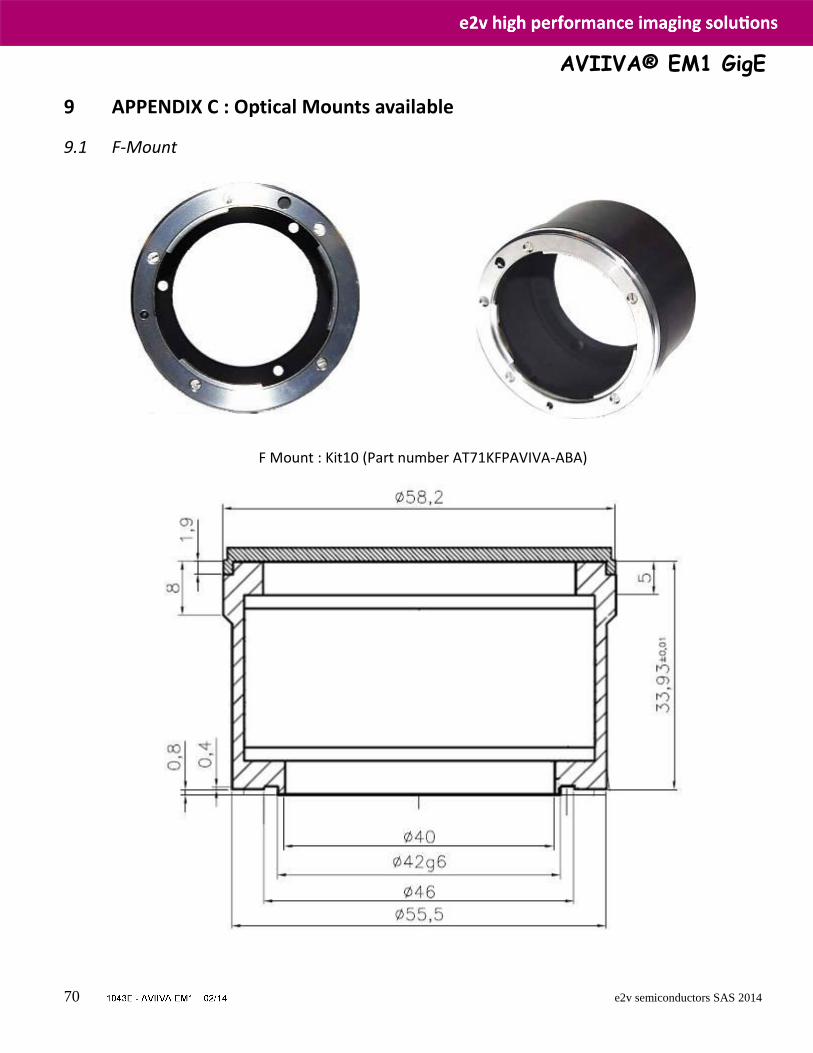
AVIIVA® EM1 GigE
70 e2v semiconductors SAS 2014
9 APPENDIX C : Optical Mounts available
9.1 F-Mount
F Mount : Kit10 (Part number AT71KFPAVIVA-ABA)
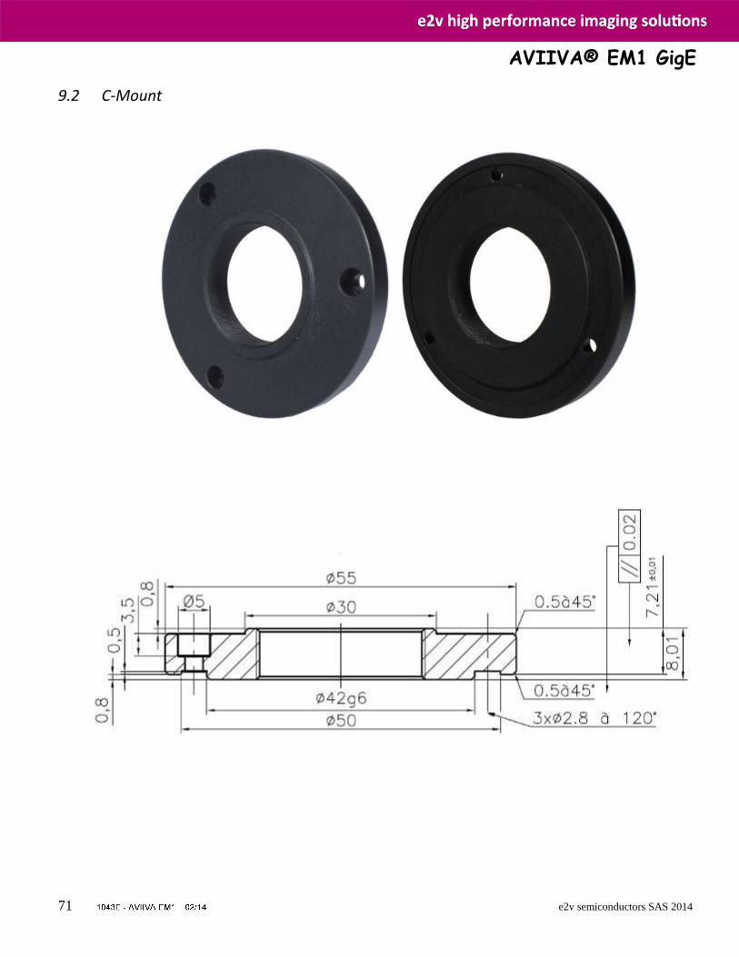
AVIIVA® EM1 GigE
71 e2v semiconductors SAS 2014
9.2 C-Mount
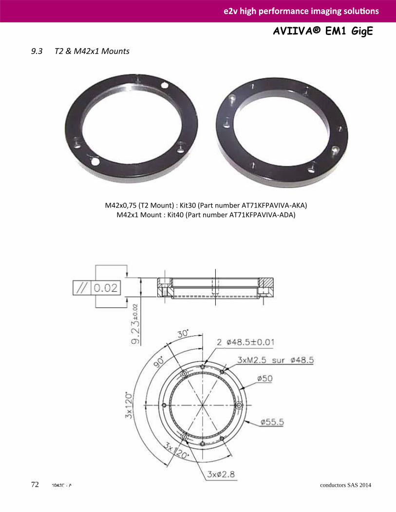
AVIIVA® EM1 GigE
72 e2v semiconductors SAS 2014
9.3 T2 & M42x1 Mounts
M42x0,75 (T2 Mount) : Kit30 (Part number AT71KFPAVIVA-AKA) M42x1 Mount : Kit40 (Part number AT71KFPAVIVA-ADA)
AVIIVA® EM1 GigE
73 e2v semiconductors SAS 2014
10 APPENDIX E : Index
AcquisitionAbort, 35 AcquisitionFrameCount, 35 AcquisitionLinePeriod, 35 AcquisitionLineRate, 35 AcquisitionMode, 35 AcquisitionStart, 35 AcquisitionStatus, 35 AcquisitionStatusSelector, 35 AcquisitionStop, 35 BlackLevel, 47 BlackLevelAutoBalance, 47 BlackLevelSelector, 47 CameraPrivilegeLevel, 32 ChangePrivilegeLevel, 32 CounterDuration, 44 CounterEventActivation, 44 CounterEventSource, 44 CounterReset, 44 CounterResetActivation, 44 CounterResetSource, 44 CounterSelector, 44 CounterStatus, 45 CounterTriggerSource, 44 CounterValue, 44 CounterValueAtReset, 45 CurrentFFCSet, 52 CurrentLUTSet, 56 CurrentUserSet, 60 DeviceFirmwareVersion, 29 DeviceID, 29 DeviceManufacturerInfo, 29 DeviceMaxThroughput, 29 DeviceModelName, 29 DeviceRegistersCheck, 29 DeviceRegistersValid, 29 DeviceScanType, 29 DeviceTemperature, 33 DeviceTemperatureSelector, 33 DeviceUserID, 29 DeviceVendorName, 29 DeviceVersion, 29 ElectronicBoardID, 29 EnableEndOfLineData, 31 EnableEndOfLineData0Source, 31
ExposureMode, 35 ExposureTime, 35 FFCAdjust, 52 FFCAdjustTarget, 52 FFCCalibrationAbort, 52 FFCCalibrationCtrl, 52 FFCEnable, 52 FFCIndex, 52 FFCSetLoad, 52 FFCSetSave, 52 FFCSetSelector, 52 FFCValue, 52 FFCValueAll, 52 FFCValueSize, 52 FPNCalibrationAbort, 52 FPNCalibrationCtrl, 52 FPNValue, 52 FPNValueAll, 52 FPNValueSize, 52 Gain, 47 GainAutoBalance, 47 GainSelector, 24, 47 GevCCP, 24, 28 GevCurrentDefaultGateway, 26 GevCurrentIPAddress, 26 GevCurrentIPConfigurationDHCP, 26 GevCurrentIPConfigurationLLA, 26 GevCurrentIPConfigurationPersistentIP, 26 GevCurrentSubnetMask, 26 GevDeviceModeCharacterSet, 26 GevDeviceModeIsBigEndian, 26 GevDiscoveryAckDelay, 27 GevFirstURL, 27 GevGVCPExtendedStatusCodes, 27 GevGVCPHeartbeatDisable, 27 GevHeartbeatTimeout, 27 GevInterfaceSelector, 26 GevLinkSpeed, 26 GevMACAddress, 26 GevMACAddressHigh, 26 GevMACAddressLow, 26 GevMCDA, 28 GevMCPHostPort, 28 GevMCRC, 28
AVIIVA® EM1 GigE
74 e2v semiconductors SAS 2014
GevMCSP, 28 GevMCTT, 28 GevMessageChannelCount, 27 GevNumberOfInterfaces, 27 GevPersistentDefaultGateway, 26 GevPersistentIPAddress, 26 GevPersistentSubnetMask, 26 GevPrimaryApplicationIPAddress, 28 GevPrimaryApplicationSocket, 28 GevSCDA, 28 GevSCPD, 28 GevSCPHostPort, 28 GevSCPInterfaceIndex, 28 GevSCPSBigEndian, 28 GevSCPSDoNotFragment, 28 GevSCPSFireTestPacket, 28 GevSCPSPacketSize, 28 GevSCSP, 28 GevSecondURL, 27 GevStreamChannelCount, 27 GevStreamChannelSelector, 28 GevSupportedOption, 27 GevSupportedOptionSelector, 27 GevTimestampControlLatch, 27 GevTimestampControlReset, 27 GevTimestampTickFrequency, 27 GevTimestampValue, 27 GevVersionMajor, 26 GevVersionMinor, 26 Height, 30 HeightMax, 30 LineAverageProfileMeasurement, 58 LineAverageProfileMeasurementAbort, 58 LineDebounceFilter, 41 LineFormat, 41 LineInverter, 41 LineMode, 41 LineSelector, 41 LineSource, 42 LineStatus, 41 LineStatusAll, 41 LUTEnable, 56 LUTIndex, 56 LUTSetLoad, 56 LUTSetSave, 56 LUTSetSelector, 56
LUTValue, 56 LUTValueAll, 56 LUTValueSize, 56 NIBlackLevelAutoBalanceAbort, 47 NIBlackLevelAutoBalanceCtrl, 47 NIGainAutoBalanceAbort, 47 NIGainAutoBalanceCtrl, 47 PayloadSize, 28 PixelAccessLineNumber, 58 PixelCoding, 30 PixelColorFilter, 30 PixelFormat, 30 PixelROIMax, 58 PixelROIMean, 58 PixelROIMin, 58 PixelROIStandardDeviation, 58 PixelROIStart, 58 PixelROIWidth, 58 PixelSize, 30 PixelValue, 59 PixelValueAll, 59 PixelValueAllIndex, 59 PixelValueSize, 59 ResetFFC, 52 ResetFPN, 52 SensorHeight, 30 SensorWidth, 30 Standby, 33 StatusErrorHardware, 33 StatusWarningFfcOrBalanceOvf, 33 StatusWarningFfcOrBalanceUdf, 33 TestImageSelector, 31 TimerDelay, 45 TimerDuration, 45 TimerSelector, 45 TimerStatus, 46 TimerTriggerActivation, 45 TimerTriggerSource, 45 TimerValue, 46 TLParamsLocked, 36 TriggerActivation, 36 TriggerDelay, 36 TriggerDivider, 36 TriggerMode, 36 TriggerPreset, 35 TriggerSelector, 36

AVIIVA® EM1 GigE
75 e2v semiconductors SAS 2014
TriggerSoftware, 36 TriggerSource, 36 UserMemoryAllIndex, 61 UserMemorySave, 61 UserMemoryValue, 61 UserMemoryValueAll, 61 UserMemoryValueSize, 61 UserOutputSelector, 42
UserOutputValue, 42 UserOutputValueAll, 42 UserOutputValueAllMask, 42 UserSetLoad, 60 UserSetSave, 60 UserSetSelector, 60 Width, 30 WidthMax, 30
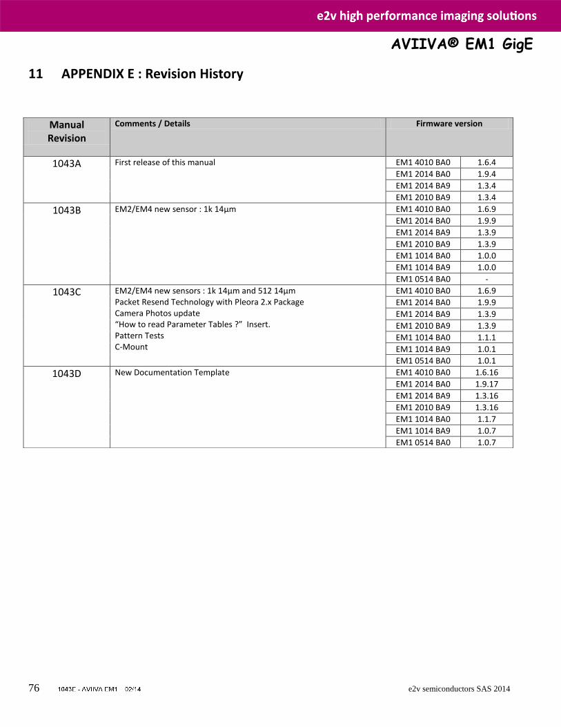
AVIIVA® EM1 GigE
76 e2v semiconductors SAS 2014
11 APPENDIX E : Revision History
Manual Revision
Comments / Details Firmware version
1043A First release of this manual EM1 4010 BA0 1.6.4
EM1 2014 BA0 1.9.4
EM1 2014 BA9 1.3.4
EM1 2010 BA9 1.3.4
1043B EM2/EM4 new sensor : 1k 14µm
EM1 4010 BA0 1.6.9
EM1 2014 BA0 1.9.9
EM1 2014 BA9 1.3.9
EM1 2010 BA9 1.3.9
EM1 1014 BA0 1.0.0
EM1 1014 BA9 1.0.0
EM1 0514 BA0 -
1043C EM2/EM4 new sensors : 1k 14µm and 512 14µm Packet Resend Technology with Pleora 2.x Package Camera Photos update “How to read Parameter Tables ?” Insert. Pattern Tests C-Mount
EM1 4010 BA0 1.6.9
EM1 2014 BA0 1.9.9
EM1 2014 BA9 1.3.9
EM1 2010 BA9 1.3.9
EM1 1014 BA0 1.1.1
EM1 1014 BA9 1.0.1
EM1 0514 BA0 1.0.1
1043D New Documentation Template EM1 4010 BA0 1.6.16
EM1 2014 BA0 1.9.17
EM1 2014 BA9 1.3.16
EM1 2010 BA9 1.3.16
EM1 1014 BA0 1.1.7
EM1 1014 BA9 1.0.7
EM1 0514 BA0 1.0.7

AVIIVA® EM1 GigE
77 e2v semiconductors SAS 2014