automation and on-line monitoring of effluent treatment plant · · 2017-03-15automation and...
TRANSCRIPT
________________________________________
*Author for correspondence; E-mail: [email protected]
Int. J. Chem. Sci.: 14(4), 2016, 3167-3178 ISSN 0972-768X
www.sadgurupublications.com
AUTOMATION AND ON-LINE MONITORING OF EFFLUENT TREATMENT PLANT
V. BAGYAVEERESWARANa*, AKSHAY VIJAYANa, M. MANIMOZHIa and R. ANITHAb
aSchool of Electrical Engineering, VIT University, VELLORE (T.N.) INDIA bSchool of Electronics Engineering, VIT University, VELLORE (T.N.) INDIA
ABSTRACT
Effluent treatment plant is mandatory for any industry, which disposes off effluents. With the introduction of automation to the plant, it reduces the downtime, optimizes the amount the raw material used, the amount of power used, the number of manpower required and thereby reducing the running cost. In the proposed automated system, parameters such as pH, electrical conductivity, total dissolved solids and temperature are read using on-line sensors. Programmable Logic Controller, Arduino UNO and Human Machine Interface (HMI) device is implanted in the system for controlling and monitoring purposes. An exclusively built Android application gives the online status of the entire system. Integrating other modules such GSM module, microSD module, Bluetooth module, LCD module further enhances the scope of the proposed system.
Key words: Programmable logic controller, HMI, Android, GSM, pH, Arduino.
INTRODUCTION
Any industries, which uses fresh water in their processes gives out effluent or wastewater, which contains a lot of polluting contaminants. It affects our environment by contaminating the water bodies, which will adversely affect the health life of all living beings. So effluent treatment plant is implanted in small to cluster of industries to treat the effluents or wastewater, which is been disposed out. However, in such treatment plants, control of operations is done manually. The physical samples are required to be collected and tested in laboratory. The parameter, which controls the process is adjusted manually by various processes to make it within acceptable range. However, this is prone to human errors
V. Bagyaveereswaran et al.: Automation and On-Line….
3168
and thus, affecting the efficiency of the system. Introducing automation to the system, it will significantly reduce any such errors caused by human intervention and also at the same time reduce the running cost in the long run by optimizing the raw material used, amount of power used and the number of human resource. Enforcing automation in effluent treatment plant will result in achieving higher quality of treated water, which can never be achieved manually.
The practical implementation and validation of advanced control strategies, designed using model based techniques at an industrial waste water treatment plant of a large pharmaceutical industry was demonstrated1,2. Satyanarayana3 discussed the need of automation in waste water treatment processes and its advantages.Sunil and Prasad4 discussed the importance of SCADA in waste water treatment plants for monitoring and controlling processes that are distributed among various remote sites and its effective working. An advanced process control algorithmic approach was proposed by Alexander5 to computerize the plant processes using micro controllers, which are designed and simulated in real time to control the flow rate of water and temperature of the plant including boiler and cooling water.Zhao et al.6 proposed an integrated automation system consisting of Process Manage System (PMS) and Process Control System (PCS) to overcome the problem of high production costs in wastewater treatment plants in China due to low automation level. The proposed system was successfully applied to the wastewater treatment plant in the southern suburb of Shenyang and achieved great benefits for both economy and society7,8. Jamil et al.9 discussed the technical solutions for the operation of fully automatic water treatment plant to achieve high efficiency in quality of productivity.
EXPERIMENTAL
Methodology
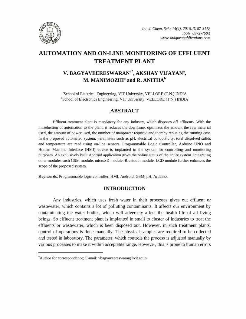
In the proposed system as shown in Fig. 1, parameters such as pH, electrical conductivity (EC), total dissolved solids (TDS), temperature, etc. are measured on-line with the help of electronic sensors. These parameters are read by a microcontroller based device such as Arduino, which is capable of decoding these analog readings to their respective units. The microcontroller will send correction signals to Programmable Logic Controller (PLC) whenever these readings goes beyond non optimum range. PLC handles the closing/opening of valves, motors etc. based on the ladder logic program designed for it. A Human Machine
Int. J. Chem. Sci.: 14(4), 2016
3169
Interface (HMI) device is implanted in the system, which provides a graphical visualization of the entire plant in which it can be controlled and monitored. The entire system is planned to be operated in an unattended manner, which can be controlled and monitored in HMI from the control center office. The GSM module, which is interfaced with Arduino is accounted for sending message in the occasion of non ideal working output. The operator can also get the status of the system from anywhere in the world by sending a message in a specific format to the system. Micro SD module acts as a data logger in the system, which logs all the reading and stores in the memory card. This is very useful to study and identify the faults in the event of non ideal output. A LCD display is interfaced to the system for displaying every reading from the sensor as long as the system is online.
Fig. 1: Block diagram of the automated system
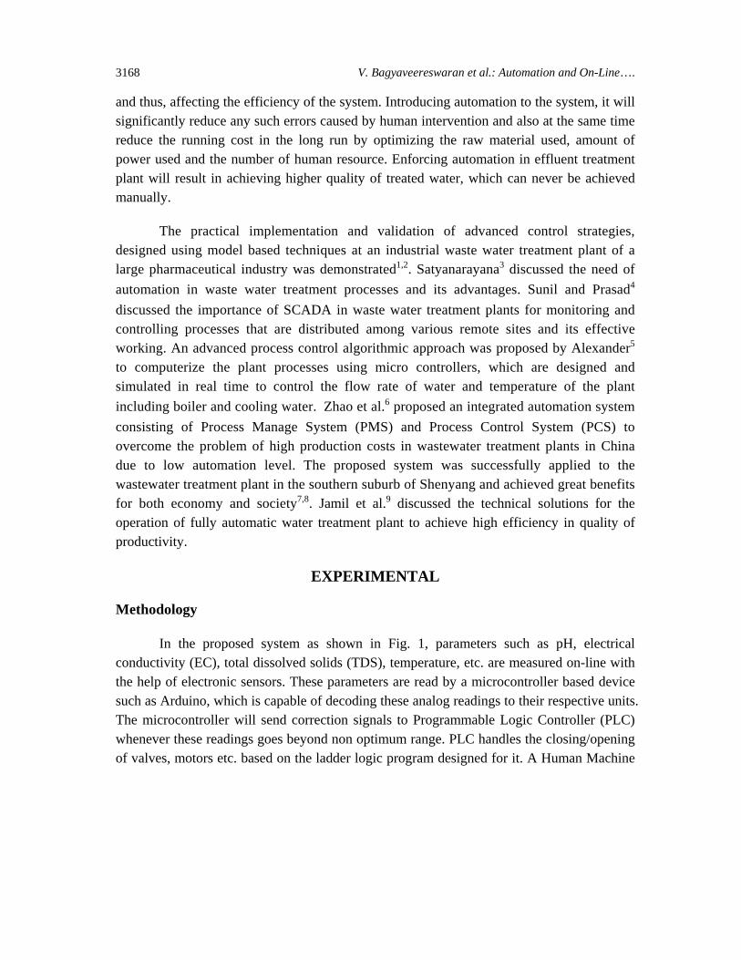
An Android application as shown in Fig. 2 is built to get the live status of the system any time the operator wants. This is done by interfacing the application with the Bluetooth module in the system. Here the readings from the sensor and status of the system is displayed on the exclusively built user friendly application, as long as it is connected to system via Bluetooth. The Android application was built using MIT inventor platform.
V. Bagyaveereswaran et al.: Automation and On-Line….
3170
Fig. 2: Android application user interface
Design requirements
The sensor design requirements are given in Table 1. The optimum pH range considered for treated water is 6-8 pH values. Effluents, which are beyond this range, needs to be neutralized and brought to optimum pH range. This realized by mixing adequate acidic or basic solutions with the effluent. Whenever Arduino detects the non optimum pH range in the effluent, it sends a correction signal to PLC, which controls the opening/closing valves of these compensation tanks. Electrical conductivity (EC) and total dissolved solids (TDS) have a linear relation. Whenever total dissolved solids in a solution increases, the conductivity in the solution also increases because this increases the amount of free charged ions in the solution.
TDS = (EC25) × (0.64 × 1000) …(1)
Where, TDS - Total dissolved solids expressed in ppm
EC25 - Equivalent EC at 25°C
Usually in industries, these values are reduced using the ultra filtration membrane skids. But this is not realizable within the scope of this project. Hence in this project, EC and
Int. J. Chem. Sci.: 14(4), 2016
3171
TDS values are reduced by adding treated water to the solution. Temperature also has an effect on the EC reading of the solution and it needs to be compensated. For this, the specific temperature was considered as 25°C.
EC25 = EC/(1 + a(T-25)) …(2)
Where, EC - Measured EC,
T - Measured temperature in °C
a - Temperature coefficient, which is equal to 0.019
Table 1: Sensor design requirements
Parameter Raw effluent characteristics
Treated effluent characteristics
pH 5-10 6-8
Electrical conductivity (S/cm) > 0.5 < 0.5
Total dissolved solids (ppm) > 750 < 500
Implementation
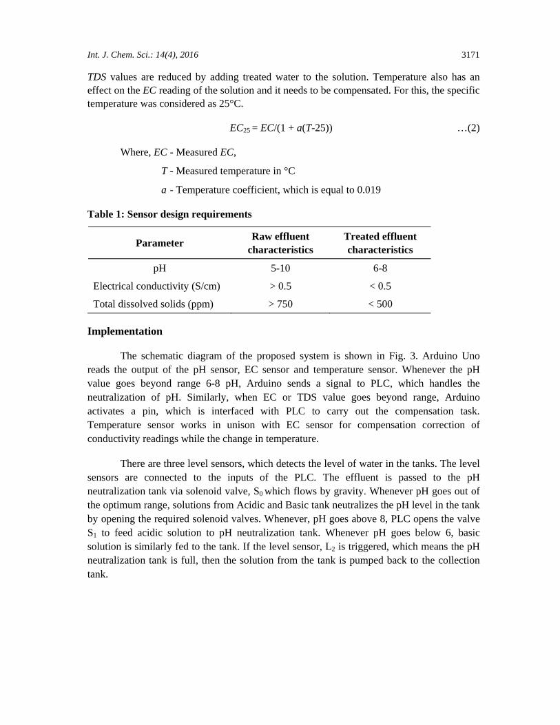
The schematic diagram of the proposed system is shown in Fig. 3. Arduino Uno reads the output of the pH sensor, EC sensor and temperature sensor. Whenever the pH value goes beyond range 6-8 pH, Arduino sends a signal to PLC, which handles the neutralization of pH. Similarly, when EC or TDS value goes beyond range, Arduino activates a pin, which is interfaced with PLC to carry out the compensation task. Temperature sensor works in unison with EC sensor for compensation correction of conductivity readings while the change in temperature.
There are three level sensors, which detects the level of water in the tanks. The level sensors are connected to the inputs of the PLC. The effluent is passed to the pH neutralization tank via solenoid valve, S0 which flows by gravity. Whenever pH goes out of the optimum range, solutions from Acidic and Basic tank neutralizes the pH level in the tank by opening the required solenoid valves. Whenever, pH goes above 8, PLC opens the valve S1 to feed acidic solution to pH neutralization tank. Whenever pH goes below 6, basic solution is similarly fed to the tank. If the level sensor, L2 is triggered, which means the pH neutralization tank is full, then the solution from the tank is pumped back to the collection tank.
V. Bagyaveereswaran et al.: Automation and On-Line….
3172
Fig. 3: Schematic diagram of the proposed system
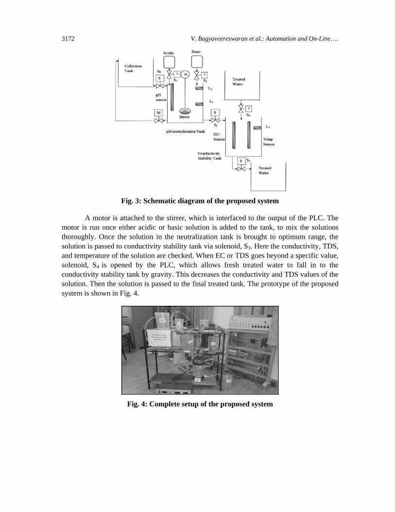
A motor is attached to the stirrer, which is interfaced to the output of the PLC. The motor is run once either acidic or basic solution is added to the tank, to mix the solutions thoroughly. Once the solution in the neutralization tank is brought to optimum range, the solution is passed to conductivity stability tank via solenoid, S3. Here the conductivity, TDS, and temperature of the solution are checked. When EC or TDS goes beyond a specific value, solenoid, S4 is opened by the PLC, which allows fresh treated water to fall in to the conductivity stability tank by gravity. This decreases the conductivity and TDS values of the solution. Then the solution is passed to the final treated tank. The prototype of the proposed system is shown in Fig. 4.
Fig. 4: Complete setup of the proposed system
Int. J. Chem. Sci.: 14(4), 2016
3173
Once the pH level goes critical high i.e. above 10 pH value, GSM module sends an SMS to the pre-specified number alerting the situation. Similarly, if it goes below 5, it alerts by sending a SMS. One can also receive status from the system, when messaged with a specific keyword to the GSM module number. The authorized personnel can even start or stop the entire system by sending message to the GSM module number using a specific keyword.
LCD display shows the status of the sensors until the system is stopped. This helps users to check the readings while in the plant site. Once the system is turned ON, its starts logging in all the data using the micro SD module interfaced in the system. With the data logs in the micro SD, one can easily find the root of cause of the problem in the event of failure.
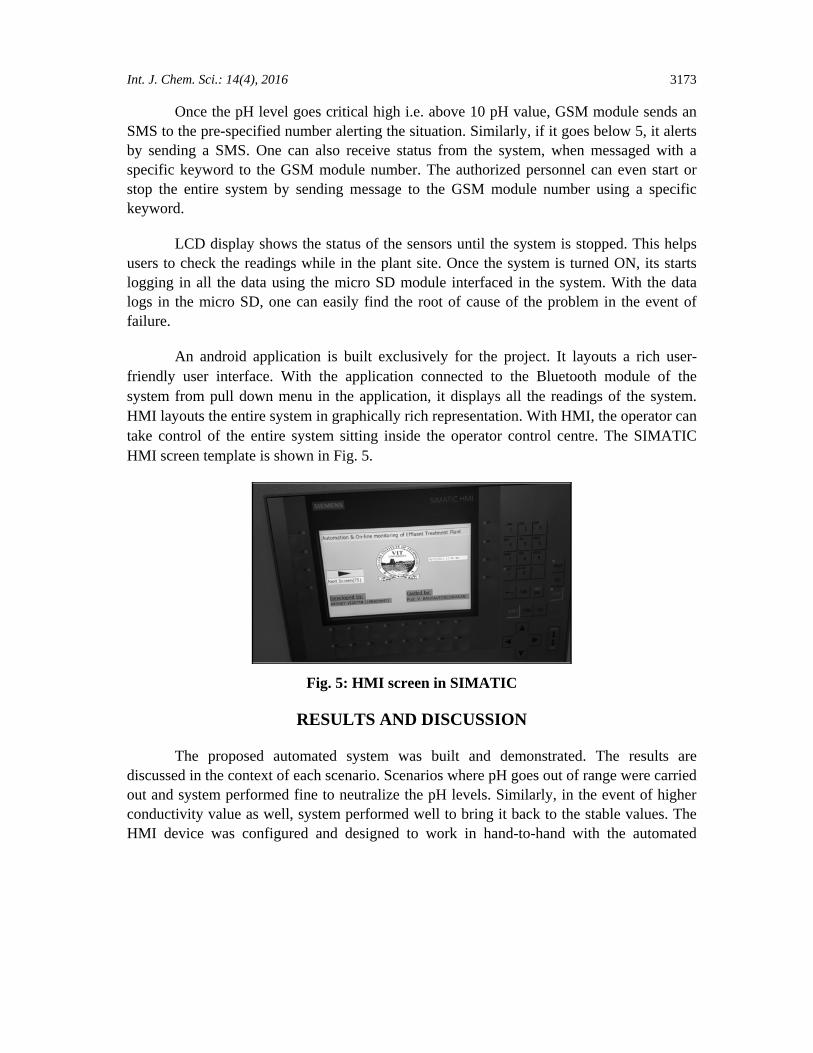
An android application is built exclusively for the project. It layouts a rich user-friendly user interface. With the application connected to the Bluetooth module of the system from pull down menu in the application, it displays all the readings of the system. HMI layouts the entire system in graphically rich representation. With HMI, the operator can take control of the entire system sitting inside the operator control centre. The SIMATIC HMI screen template is shown in Fig. 5.
Fig. 5: HMI screen in SIMATIC
RESULTS AND DISCUSSION
The proposed automated system was built and demonstrated. The results are discussed in the context of each scenario. Scenarios where pH goes out of range were carried out and system performed fine to neutralize the pH levels. Similarly, in the event of higher conductivity value as well, system performed well to bring it back to the stable values. The HMI device was configured and designed to work in hand-to-hand with the automated
V. Bagyaveereswaran et al.: Automation and On-Line….
3174
system. With HMI, operator can overide the automated system functioning and take control of the processes. This is especially helpful in the event of some unknown natural errors. HMI can be placed away from the plant in the control operator centre room, so that operator can get thorough insight of the plant processes even without going to the plant. The SIMATIC HMI system layout is shown in Fig. 6.
Fig. 6: HMI system layout
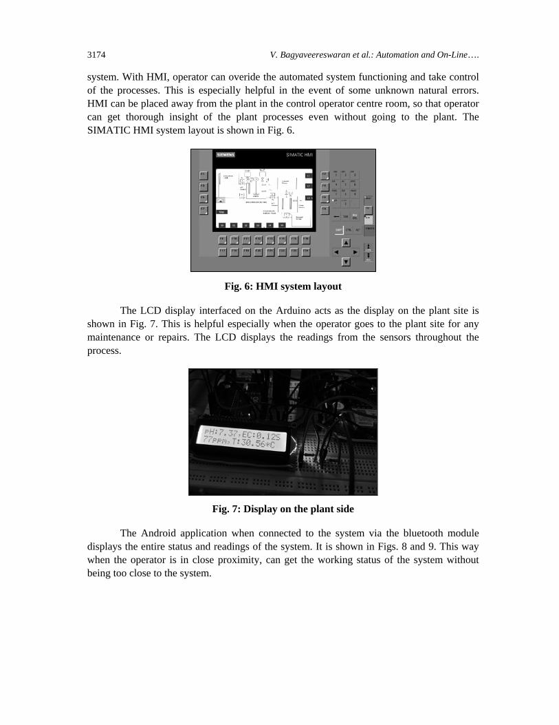
The LCD display interfaced on the Arduino acts as the display on the plant site is shown in Fig. 7. This is helpful especially when the operator goes to the plant site for any maintenance or repairs. The LCD displays the readings from the sensors throughout the process.
Fig. 7: Display on the plant side
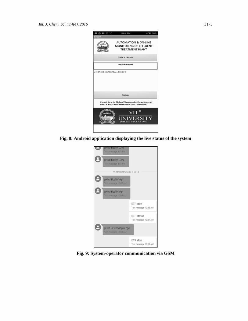
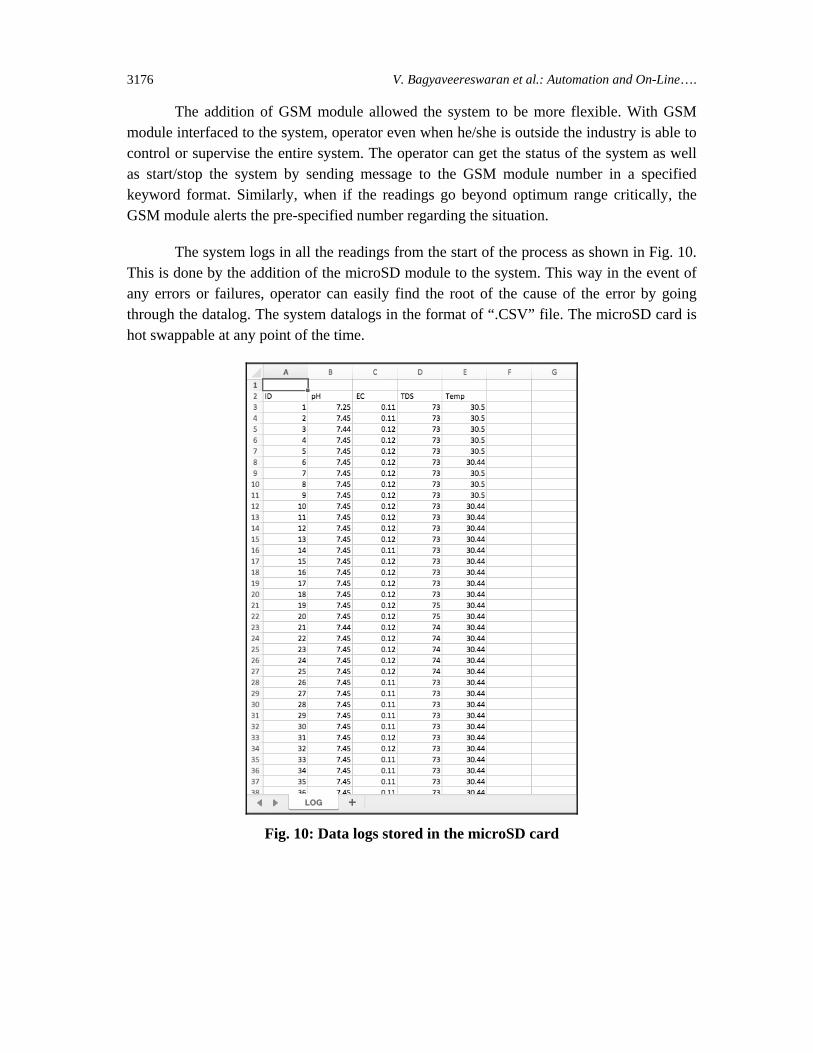
The Android application when connected to the system via the bluetooth module displays the entire status and readings of the system. It is shown in Figs. 8 and 9. This way when the operator is in close proximity, can get the working status of the system without being too close to the system.
Int. J. Chem. Sci.: 14(4), 2016
3175
Fig. 8: Android application displaying the live status of the system
Fig. 9: System-operator communication via GSM
V. Bagyaveereswaran et al.: Automation and On-Line….
3176
The addition of GSM module allowed the system to be more flexible. With GSM module interfaced to the system, operator even when he/she is outside the industry is able to control or supervise the entire system. The operator can get the status of the system as well as start/stop the system by sending message to the GSM module number in a specified keyword format. Similarly, when if the readings go beyond optimum range critically, the GSM module alerts the pre-specified number regarding the situation.
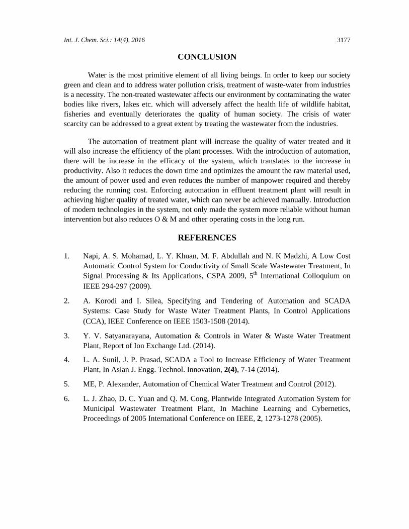
The system logs in all the readings from the start of the process as shown in Fig. 10. This is done by the addition of the microSD module to the system. This way in the event of any errors or failures, operator can easily find the root of the cause of the error by going through the datalog. The system datalogs in the format of “.CSV” file. The microSD card is hot swappable at any point of the time.
Fig. 10: Data logs stored in the microSD card
Int. J. Chem. Sci.: 14(4), 2016
3177
CONCLUSION
Water is the most primitive element of all living beings. In order to keep our society green and clean and to address water pollution crisis, treatment of waste-water from industries is a necessity. The non-treated wastewater affects our environment by contaminating the water bodies like rivers, lakes etc. which will adversely affect the health life of wildlife habitat, fisheries and eventually deteriorates the quality of human society. The crisis of water scarcity can be addressed to a great extent by treating the wastewater from the industries.
The automation of treatment plant will increase the quality of water treated and it will also increase the efficiency of the plant processes. With the introduction of automation, there will be increase in the efficacy of the system, which translates to the increase in productivity. Also it reduces the down time and optimizes the amount the raw material used, the amount of power used and even reduces the number of manpower required and thereby reducing the running cost. Enforcing automation in effluent treatment plant will result in achieving higher quality of treated water, which can never be achieved manually. Introduction of modern technologies in the system, not only made the system more reliable without human intervention but also reduces O & M and other operating costs in the long run.
REFERENCES
1. Napi, A. S. Mohamad, L. Y. Khuan, M. F. Abdullah and N. K Madzhi, A Low Cost Automatic Control System for Conductivity of Small Scale Wastewater Treatment, In Signal Processing & Its Applications, CSPA 2009, 5th International Colloquium on IEEE 294-297 (2009).
2. A. Korodi and I. Silea, Specifying and Tendering of Automation and SCADA Systems: Case Study for Waste Water Treatment Plants, In Control Applications (CCA), IEEE Conference on IEEE 1503-1508 (2014).
3. Y. V. Satyanarayana, Automation & Controls in Water & Waste Water Treatment Plant, Report of Ion Exchange Ltd. (2014).
4. L. A. Sunil, J. P. Prasad, SCADA a Tool to Increase Efficiency of Water Treatment Plant, In Asian J. Engg. Technol. Innovation, 2(4), 7-14 (2014).
5. ME, P. Alexander, Automation of Chemical Water Treatment and Control (2012).
6. L. J. Zhao, D. C. Yuan and Q. M. Cong, Plantwide Integrated Automation System for Municipal Wastewater Treatment Plant, In Machine Learning and Cybernetics, Proceedings of 2005 International Conference on IEEE, 2, 1273-1278 (2005).
V. Bagyaveereswaran et al.: Automation and On-Line….
3178
7. A. Archana and B. Yadav, PLC & SCADA Based Automation of Filter House, A Section of Water Treatment Plant, In Emerging Technology Trends in Electronics, Communication and Networking (ET2ECN), 1st International Conference on IEEE, 1-6 (2012).
8. J. A. Lynggaard, Trends in Monitoring of Waste Water Systems, Talanta, 50(4), 707-716 (1999).
9. I. Jamil, R. Jamil, R. Jamil, Z. Jinquan and A. Samee, Technical Communication of Automation Control System in Water Treatment Plant, Int. J. Innovation Appl. Studies, 2028-9324 (2013).
Accepted : 04.10.2016