audel air conditioning home and commercial
DESCRIPTION
Air conditioningTRANSCRIPT


P1: GDZ/FFX P2: GDZ/FFX QC: GDZ/FFX T1: GDZ
GB076-Miller-FM GB076-Miller-Sample July 14, 2004 20:16 Char Count= 0
AudelTM
Air Conditioning: Homeand Commercial
All New 5th Edition
i

P1: GDZ/FFX P2: GDZ/FFX QC: GDZ/FFX T1: GDZ
GB076-Miller-FM GB076-Miller-Sample July 14, 2004 20:16 Char Count= 0
ii
P1: GDZ/FFX P2: GDZ/FFX QC: GDZ/FFX T1: GDZ
GB076-Miller-FM GB076-Miller-Sample July 14, 2004 20:16 Char Count= 0
AudelTM
Air Conditioning: Homeand Commercial
All New 5th Edition
Rex MillerMark Richard Miller
Edwin P. Anderson
iii
P1: GDZ/FFX P2: GDZ/FFX QC: GDZ/FFX T1: GDZ
GB076-Miller-FM GB076-Miller-Sample July 14, 2004 20:16 Char Count= 0
Vice President and Executive Group Publisher: Richard SwadleyVice President and Executive Publisher: Robert IpsenVice President and Publisher: Joseph B. WikertExecutive Editor: Carol A. LongEditorial Manager: Kathryn A. MalmDevelopment Editor: Kevin ShaferProduction Editor: Vincent KunkemuellerText Design & Composition: TechBooks
Copyright C© 2004 by Wiley Publishing, Inc. All rights reserved.
Published simultaneously in Canada
No part of this publication may be reproduced, stored in a retrieval system, or transmit-ted in any form or by any means, electronic, mechanical, photocopying, recording, scan-ning, or otherwise, except as permitted under Section 107 or 108 of the 1976 United StatesCopyright Act, without either the prior written permission of the Publisher, or authorizationthrough payment of the appropriate per-copy fee to the Copyright Clearance Center, Inc.,222 Rosewood Drive, Danvers, MA 01923, (978) 750-8400, fax (978) 646-8700. Requests tothe Publisher for permission should be addressed to the Legal Department, Wiley Publishing, Inc.,10475 Crosspoint Blvd., Indianapolis, IN 46256, (317) 572-3447, fax (317) 572-4447, E-mail:[email protected].
Limit of Liability/Disclaimer of Warranty: The publisher and the author make no representa-tions or warranties with respect to the accuracy or completeness of the contents of this workand specifically disclaim all warranties, including without limitation warranties of fitness for aparticular purpose. No warranty may be created or extended by sales or promotional materials.The advice and strategies contained herein may not be suitable for every situation. This workis sold with the understanding that the publisher is not engaged in rendering legal, accounting,or other professional services. If professional assistance is required, the services of a competentprofessional person should be sought. Neither the publisher nor the author shall be liable fordamages arising herefrom. The fact that an organization or web site is referred to in this workas a citation and/or a potential source of further information does not mean that the authoror the publisher endorses the information the organization or web site may provide or recom-mendations it may make. Further, readers should be aware that Internet web sites listed in thiswork may have changed or disappeared between when this work was written and when it isread. For general information on our other products and services please contact our CustomerCare Department within the United States at (800) 762-2974, outside the United States at (317)572-3993 or fax (317) 572-4002.
Trademarks: Wiley, the Wiley Publishing logo, and Audel are trademarks or registered trademarksof John Wiley & Sons, Inc., and/or its affiliates. All other trademarks are the property of theirrespective owners. Wiley Publishing, Inc., is not associated with any product or vendor mentionedin this book.
Wiley also publishes its books in a variety of electronic formats. Some content that appears inprint may not be available in electronic books.
Library of Congress Control Number:
Printed in the United States of America
10 9 8 7 6 5 4 3 2 1
iv
eISBN: 0-7645-7719-0

P1: GDZ/FFX P2: GDZ/FFX QC: GDZ/FFX T1: GDZ
GB076-Miller-FM GB076-Miller-Sample July 14, 2004 20:16 Char Count= 0
Contents
Acknowledgments xix
About the Authors xxi
Introduction xxiii
Chapter 1 Air-Conditioning Fundamentals 1Properties of Air 1Air Circulation 2Cleaning and Filtering 2Basic Information 3
Heat Transfer 3Sensible Heat 4Specific Heat 4Latent Heat 4Latent Heat of Fusion 4Latent Heat of Evaporation 5Superheat 5Pressure–Temperature Relationship 5
Measurements and Measuring Devices 7Thermometer 7Barometer 8Sling Psychrometer 9Pressure Gages 10British Thermal Unit 10Refrigeration Capacity Measurements 10
Summary 12Review Questions 13
Chapter 2 Psychrometry 15Air and Water-Vapor Mixtures 15Humidifying and Dehumidifying 15Relative Humidity 15
Relative Humidity Measurements 16Grains of Moisture 16Specific Volume 17
v
P1: GDZ/FFX P2: GDZ/FFX QC: GDZ/FFX T1: GDZ
GB076-Miller-FM GB076-Miller-Sample July 14, 2004 20:16 Char Count= 0
vi Contents
Dew-Point Temperature 17Effective Temperature 17Dry-Bulb Temperature 17Wet-Bulb Temperature 17Wet-Bulb Depression 18Temperature-Humidity Index 18Total Heat Content 18
Psychrometric Charts 18Psychrometric Chart Instructions 19Calculation Examples 19
Comfort Chart 25Summary 27Review Questions 27
Chapter 3 Heat Leakage 29Calculation Examples 30
Example 30Solution 30
Reference Tables 30Summary 52Review Questions 52
Chapter 4 Ventilation Requirements 53Air Leakage 53Natural Ventilation 53
Wind Forces 53Temperature-Difference Forces 54Combined Wind and Temperature Forces 55Roof Ventilators 55Ventilator Capacity 56
Fresh-Air Requirements 57Mechanical Ventilation 58
Volume of Air Required 58Duct-System Resistance 59
Air Filtration 60Effect of Dust on Health 60Various Dust Sources 61

P1: GDZ/FFX P2: GDZ/FFX QC: GDZ/FFX T1: GDZ
GB076-Miller-FM GB076-Miller-Sample July 14, 2004 20:16 Char Count= 0
Contents vii
Air-Filter Classification 61Dry Filters 62Wet (or Viscous) Filters 63
Filter Installation 66Humidity-Control Methods 69Humidifiers 69
Air-Washer Method 69Pan Humidifiers 70Electrically Operated Humidifiers 71Air-Operated Humidifiers 71
Dehumidifiers 73Electric Dehumidification 74Controls 75Adsorption-Type Dehumidifiers 76
Air-Duct Systems 77Heat Gains in Ducts 79Resistance Losses in Duct Systems 85
Fans and Blowers 89Air Volume 90Horsepower Requirements 90Drive Methods 91Fan Selection 92Fan Applications 93Fan Operation 94Attic-Fan Installation 95Fan Operation 97
Summary 97Review Questions 98
Chapter 5 Room Air Conditioners 101Operation 101Cooling Capacity 103Capacity Requirements 103Installation Methods 104
Double-Hung Window Installation 106Casement Window Installation 111Outside Support Bracket 115
P1: GDZ/FFX P2: GDZ/FFX QC: GDZ/FFX T1: GDZ
GB076-Miller-FM GB076-Miller-Sample July 14, 2004 20:16 Char Count= 0
viii Contents
Console-Type Room Air-ConditioningSystems 116
Electrical System 122Electrical Components 124Fan Motors 127Thermostats 128Unit Control Switch 129
Service Operations 129Dismantling Window Air Conditioners 130Electrical Testing 130Compressor and Motor 135Oiling of Motors 137Leaks in System 137Filters 137Interior Cleaning 137Winter Care 137Refrigerant-System Service 138
Troubleshooting Guide(Window-Mounted Units) 143Summary 143Review Questions 145
Chapter 6 Refrigerants 147Desirable Properties 147Chlorofluorocarbon Compounds (CFCs) 147Classifications 148Early Types of Refrigerants 150
Sulfur Dioxide 151Methyl Chloride 151Ethyl Chloride 152Ammonia 153Carbon Dioxide 154Freezol (Isobutane) 154Calcium Chloride (CaCl2) 154
Freon Refrigerants 156Classifications 156Properties of Freons 157

P1: GDZ/FFX P2: GDZ/FFX QC: GDZ/FFX T1: GDZ
GB076-Miller-FM GB076-Miller-Sample July 14, 2004 20:16 Char Count= 0
Contents ix
Pressure-Temperature Chart 160Refrigerant Characteristics 160
Critical Temperature 160Hydrofluorocarbons (HFCs) 162Latent Heat of Evaporation 162Specific Heat 163Power Consumption 163Volume of Liquid Circulated 164
Simple Refrigeration System 164Handling Refrigerants 166
Storing and Handling RefrigerantCylinders 166Cylinder Capacity 167First Aid 168
Summary 169Review Questions 169
Chapter 7 Compressors for Air Conditioners 171Mechanical Components 171
Compressors 171Condensers 173Receivers 173Evaporators 173Refrigerant Controls 174Expansion Valves 174
Refrigeration Cycle 174Refrigerants 175Compressors 176
Reciprocating Compressors 177Drive Methods 177Compressor Valves 178Pistons and Piston Rings 178Connecting Rods 181Crankshafts 181Shaft Seals 183Lubrication and Cooling 184
Rotary Compressors 184

P1: GDZ/FFX P2: GDZ/FFX QC: GDZ/FFX T1: GDZ
GB076-Miller-FM GB076-Miller-Sample July 14, 2004 20:16 Char Count= 0
x Contents
Scroll Compressors 189Scroll Compression Process 189Operation 191Scroll Compressor Models 192
Centrifugal Compressors 192Construction Features 195Lubrication System 196
Installation and Maintenance 198Foundation 198Motor and Belts 199Compressor Flow-Back Protection 199Valve Maintenance 200Shaft-Seal Leaks 201Compressor Knocks 202Stuck or Tight Compressor 202Compressor Removal 202Compressor Replacement 203Compressor Startup 203Winter Shutdown of Water-CooledCompressors 204
Compressor Characteristics 205Compressor Performance 205Compressor Capacity 205Mechanical Efficiency 205Volumetric Efficiency 205Compressor Efficiency Test 205
Troubleshooting Guide 214Summary 214Review Questions 215
Chapter 8 Condensing Equipment for AirConditioners 217Air-Cooled Condensers 217Water-Cooled Condensers 219
Cooling-Water Circuits 220Types of Water-Cooled Condensers 220

P1: GDZ/FFX P2: GDZ/FFX QC: GDZ/FFX T1: GDZ
GB076-Miller-FM GB076-Miller-Sample July 14, 2004 20:16 Char Count= 0
Contents xi
Head-Pressure Control Methods 228Water-Cooled Condensers 228Evaporative Condensers 229Air-Cooled Condensers 230
Condenser Maintenance 232Cleaning Precautions 233Charging the System 235Cleaning Time 235Flushing the System 235Cleaning Evaporative Condensers 235Removing Scale Formation 236Gravity and Forced Circulation 236
Outdoor Condensing Units 237Summary 238Review Questions 239
Chapter 9 Evaporators for Air Conditioners 241Types of Evaporators 241
Finned Evaporators 242Plain-Tubing Evaporators 242Evaporator-Coil Construction 243
Refrigerant-Control Methods 245Superheat 245Chilling Units 247Dry-Expansion Coil Arrangements 249Capacity Requirements 251
Evaporator Calculations 251Exterior Conditions 253Surface-Area Determination 253
Evaporator Maintenance 255Cycling the Condensing Unit 255Time Clocks 256
Accessory Equipment 257Heat Exchangers 257Surge Drums 260Oil Separators 260Driers 263

P1: GDZ/FFX P2: GDZ/FFX QC: GDZ/FFX T1: GDZ
GB076-Miller-FM GB076-Miller-Sample July 14, 2004 20:16 Char Count= 0
xii Contents
Dehydrators 264Strainers 265Mufflers 266Subcoolers 266Check Valves 267
Summary 269Review Questions 271
Chapter 10 Water-Cooling Systems 273Atmospheric Cooling Methods 274
Water Towers 274Cooling Ponds 278Spray-Cooling Ponds 279
New Developments 279Cooling-Unit Piping 280
Liquid Lines 281Suction Lines 282Oil Circulation 283Discharge Lines 283Refrigerant-Piping Arrangement 284
Summary 287Review Questions 288
Chapter 11 Air-Conditioning Control Methods 289Types of Air-Conditioning Controls 289
Manual Control 289Automatic Control 290Semiautomatic Control 290
Basic Control Types 290Room Thermostats 291Twin-Type Thermostats 294Duct Thermostats 294Immersion Thermostats 295Hygrostats 295Pressure Regulators 297
Limit Controls 297Control Valves 298
P1: GDZ/FFX P2: GDZ/FFX QC: GDZ/FFX T1: GDZ
GB076-Miller-FM GB076-Miller-Sample July 14, 2004 20:16 Char Count= 0
Contents xiii
Dampers 299Relays 299Refrigerant Control Devices 300
Automatic Expansion Valves 300Thermostatic Expansion Valves 300Sizing of Thermostatic ExpansionValves 302Low-Side Float Valves 303High-Side Float Valves 305Capillary Tubes 305Crankcase Pressure-Regulating Valve 305Evaporator Pressure-Regulating Valve 306Reversing Valves 306
Summary 308Review Questions 309
Chapter 12 Weather Data and Design Conditions 311Indoor Design Conditions 311Outdoor Design Conditions 312
Winter 312Summer 313
Interpolation among Stations 326Weather-Oriented Design Factors 326Summary 328Review Questions 329
Chapter 13 Year-Round Central Air Conditioning 331Central System Features 331
Air-Supply System 332Mixing Chamber 332Heating Coils 333Preheaters 333Cooling Coils 334Air-Supply Fans 334Filters 335Air Washers 335Control Method 335

P1: GDZ/FFX P2: GDZ/FFX QC: GDZ/FFX T1: GDZ
GB076-Miller-FM GB076-Miller-Sample July 14, 2004 20:16 Char Count= 0
xiv Contents
Zone Control 336System Selection 337
Absorption-Type Air Conditioning 338Absorption versus Compression 338Cycle of Operation 339
Reverse-Cycle Air Conditioning(Heat Pumps) 341
Reversing Valve Operation 342Control Equipment 345Defrost-Cycle Operation 346Installation and Maintenance 347Indoor Arrangement 347Refrigerant Tubing 348Quick-Connect Couplings 350System Troubles 353
Reversing-Valve Troubleshooting Guide 354Nonportable Air Conditioners 354
Construction Principles 358Plumbing Connections 358Water-Cooling Tower 359Heating Coils 361
Suspended-Type Air Conditioners 361Casings 362Coils 362Filters 363Controls 363
Air-Conditioning TroubleshootingGuide 363Summary 366Review Questions 366
Chapter 14 Automobile Air Conditioning 369Air-Conditioning System Operation 373Component Description 375
Compressors 375Condensers 376Receiver-Dehydrator 377

P1: GDZ/FFX P2: GDZ/FFX QC: GDZ/FFX T1: GDZ
GB076-Miller-FM GB076-Miller-Sample July 14, 2004 20:16 Char Count= 0
Contents xv
Thermostatic Expansion Valves 377Evaporators 380Solenoid Control 380Magnetic-Clutch Control 381Suction-Throttle Control 382Air Distribution 384Air-Conditioner Control System 384
Service and Maintenance 384Insufficient or No Cooling 385Air Output Not Normal 385Air Output Normal 385Checking Suction Pressures 386Checking Control Systems 386Air Distribution 386Defective Compressor 386Compressor Clutch 387Condenser 387Thermostatic Expansion Valve 387Evaporator 388Refrigerant Lines 388Suction-Throttle Valve 388Use of Receiver Sight Glass for Diagnosis 389
Installation Procedure 389Troubleshooting Guide 395Summary 395Review Questions 396
Chapter 15 Motors and Motor Controls 399Motor Voltage 399Polyphase Motors 399
Squirrel Cage Motors 400Wound-Rotor Motors 401Synchronous Motors 403
Single-Phase Motors 406Split-Phase Motors 406Capacitor-Start Motors 407Two-Value Capacitor Motors 408

P1: GDZ/FFX P2: GDZ/FFX QC: GDZ/FFX T1: GDZ
GB076-Miller-FM GB076-Miller-Sample July 14, 2004 20:16 Char Count= 0
xvi Contents
Permanent Split-Capacitor Motors 408Repulsion Induction Motors 409Repulsion-Start Induction Motors 409Capacitors 411
AC Motor Controls 413Squirrel Cage Motors 413Wound-Rotor Motors 414Synchronous Motors 416
Single-Phase Motor Controls 418Overload Protectors 418Start Relays 419
Compressor Motor Controls 420Temperature-Motor Control 420Pressure-Motor Control 421Solenoid Valves 421Condensing-Water Controls 421
Belt Drives 422Motor Maintenance 422Horsepower Calculations 423
Motor Horsepower Calculated fromMeter Readings 423Horsepower Calculated from Load(Mechanics’ Data) 424Horsepower Calculations for SpecificApplications (Approximate) 424Power-Conversion Factors 425
Troubleshooting Guide 425Summary 425Review Questions 428
Chapter 16 Maintenance 431General Procedure 431Head Pressures 432Suction Pressure 433Back Pressure 434Refrigerant Charge 434Compressor Service Valves 435

P1: GDZ/FFX P2: GDZ/FFX QC: GDZ/FFX T1: GDZ
GB076-Miller-FM GB076-Miller-Sample July 14, 2004 20:16 Char Count= 0
Contents xvii
Gages 436Combination Gages 437Adding Refrigerant 437Removing Refrigerant 439Adding Oil 439Removing Oil 439System Pump-Down 440Purging System of Noncondensables 441Leak Test 441
Halide-Torch Method (For FreonRefrigerants) 441Electronic Leak Detector 442
Evacuating the System 443Checking Compressor Valves 444Troubleshooting Guide 444Summary 450Review Questions 451
Appendix A Professional Organizations 453
Glossary 459
Index 481

P1: GDZ/FFX P2: GDZ/FFX QC: GDZ/FFX T1: GDZ
GB076-Miller-FM GB076-Miller-Sample July 14, 2004 20:16 Char Count= 0
xviii
P1: GDZ/FFX P2: GDZ/FFX QC: GDZ/FFX T1: GDZ
GB076-Miller-FM GB076-Miller-Sample July 14, 2004 20:16 Char Count= 0
Acknowledgments
No book can be written without the aid of many people. It takes agreat number of individuals to put together the information avail-able about any particular technical field into a book. The field of airconditioning is no exception. Many firms have contributed to theinformation, illustrations, and analysis of the book.
The authors would like to thank every person involved for hisor her contributions. Following are some of the firms that suppliedtechnical information and illustrations.
Acme Industrial, Inc.American Society of Heating and Ventilating EngineersAmerican Standard ControlsArmstrong Machine WorksASHRAEAutomatic Products, Inc.Barneby Cheney CorporationBuffalo Forge CompanyCargoaire Engineering CorporationCarrier CorporationControls Company of AmericaCopeland Refrigeration CorporationCrocker-Wheeler CorporationDunham-Bush, Inc.Frick CompanyGeneral Electric CompanyGeneral Motors CorporationGibson Refrigerator Sales CorporationHoneywell, Inc.Hotpoint Co.LennoxMarsh Instruments Co. Inc.Mueller Brass Co.Paragoan Electric CompanyPenn Controls, Inc.
xix
P1: GDZ/FFX P2: GDZ/FFX QC: GDZ/FFX T1: GDZ
GB076-Miller-FM GB076-Miller-Sample July 14, 2004 20:16 Char Count= 0
xx Acknowledgments
Ranco InternationalRefrigeration Research, Inc.Rockwell-Standard CorporationRudd Manufacturing CompanySporlan Valve CorporationTaylor Instrument CompanyTecumsehTrane CompanyTurner CorporationWestinghouse CorporationWorthington Corporation
P1: GDZ/FFX P2: GDZ/FFX QC: GDZ/FFX T1: GDZ
GB076-Miller-FM GB076-Miller-Sample July 14, 2004 20:16 Char Count= 0
About the Authors
Rex Miller was a Professor of Industrial Technology at The StateUniversity of New York, College at Buffalo for more than 35 years.He has taught on the technical school, high school, and college levelfor more than 40 years. He is the author or co-author of more than100 textbooks ranging from electronics through carpentry and sheetmetal work. He has contributed more than 50 magazine articles overthe years to technical publications. He is also the author of sevencivil war regimental histories.
Mark Richard Miller finished his BS degree in New York and movedon to Ball State University, where he obtained the masters and wentto work in San Antonio. He taught in high school and went tograduate school in College Station, Texas, finishing the doctorate.He took a position at Texas A&M University in Kingsville, Texaswhere he now teaches in the Industrial Technology Department asa Professor and Department Chairman. He has co-authored sevenbooks and contributed many articles to technical magazines. Hishobbies include refinishing a 1970 Plymouth Super Bird and a 1971Road-runner.
Edwin P. Anderson was a professional engineer and the author ofnumerous books for the trades, including air conditioning, sheetmetal, home appliance, and electrical.
xxi

P1: GDZ/FFX P2: GDZ/FFX QC: GDZ/FFX T1: GDZ
GB076-Miller-FM GB076-Miller-Sample July 14, 2004 20:16 Char Count= 0
xxii

P1: GDZ/FFX P2: GDZ/FFX QC: GDZ/FFX T1: GDZ
GB076-Miller-FM GB076-Miller-Sample July 14, 2004 20:16 Char Count= 0
Introduction
This book is designed to fill the need for a concise, basic book forthose who are in need of acquiring practical information on theinstallation, operation, and servicing of air-conditioning equipmentin the home, as well as in the commercial and industrial applications.The subject is presented in a simple non-technical language, yet thetreatment is sufficiently complete to enable the reader to diagnoseand correct troubles that may occur from time to time.
The material in this book has been carefully organized to pro-vide a practical understanding of the construction, operation, andfundamentals so important to diagnosing operating faults in an air-conditioning system. A complete description of the purpose andfunction of each operating component, along with a full coverageof refrigerants used in various applications, is included.
Each chapter is fully illustrated. Numerous troubleshootingcharts will assist the operator or service technician in the properdiagnosis and prompt repair procedure to use when a malfunctionoccurs.
xxiii

P1: GDZ/FFX P2: GDZ/FFX QC: GDZ/FFX T1: GDZ
GB076-Miller-FM GB076-Miller-Sample July 14, 2004 20:16 Char Count= 0
xxiv

P1: GDZ/FFX P2: GDZ/FFX QC: GDZ/FFX T1: GDZ
GB076-01 GB076-Miller-Sample July 14, 2004 22:26 Char Count= 0
Chapter 1Air-Conditioning FundamentalsAir conditioning may be defined as the simultaneous control of all(or at least the first three) of those factors affecting both the physicaland chemical conditions of the atmosphere within any structure.These factors include temperature, humidity, motion, distribution,dust, bacteria, odors, and toxic gases, most of which affect humanhealth and comfort to a greater or lesser degree.
Air that has been properly conditioned has had one (or a combi-nation) of the foregoing processes performed on it. For example, ithas been heated or cooled; it has had moisture removed from it (de-humidified); it has been placed in motion by means of fans or otherapparatus; and it has been filtered and cleaned. These processes maybe placed in the following order for ready reference:
1. Heating.2. Cooling.3. Humidifying.4. Dehumidifying.5. Circulating.6. Cleaning and filtering.
The impression prevailing in many instances is that refrigeratingor heating equipment cools or heats a room. This is only partly truesince all the work performed by the equipment is on the air withinthe room, not on the room itself. In this connection, it is good toremember that air is only a vehicle or conveyance used to transportheat and moisture from one point to another. Air is a tangible item,and every cubic foot of air surrounding a person has a certain weight,depending on its temperature, the amount of moisture it is carrying,and its altitude above sea level.
Properties of AirAir is a mixture made up primarily of two gases, being approx-imately 23 parts oxygen and 77 parts nitrogen by weight. Othergases in air include carbon dioxide, carbon monoxide, ozone, neon(in small quantities), and certain gases that are of no particular in-terest in the field of air conditioning.
Ozone is produced by sparks around electrical equipment andby the discharge of atmospheric electricity or lightning. Neon isa gas in its normal form and is used in signs for advertising.
1
P1: GDZ/FFX P2: GDZ/FFX QC: GDZ/FFX T1: GDZ
GB076-01 GB076-Miller-Sample July 14, 2004 22:26 Char Count= 0
2 Chapter 1
Carbon monoxide is not present in the atmosphere except in con-gested motor traffic. It is dangerous, being produced by the incom-plete combustion of carbon. It is also given off by stoves, furnaces,and cigarettes. Air containing carbon monoxide in excess of 1/10 of1 percent is fatal to human beings.
Oxygen, the most important constituent of air, constitutes aboutone-fourth of the air by weight and one-fifth of the air by volume,and on it depends the existence of all animal life. Nitrogen is arelatively inert gas whose principal function is to dilute oxygen.
Air CirculationAir-conditioning equipment must circulate a sufficient volume of airat all times for two main reasons:
� The air must be constantly moving to carry away the mois-ture and heat immediately surrounding the body. If this is notdone, the occupants soon become uncomfortable, even thoughthe relative humidity of the room as a whole is comparativelylow.� The air must be constantly drawn into the conditioner and
passed out over the cool evaporator so that the moisture itabsorbs from the room may be condensed and eliminatedthrough the drain.
Although the movement of a sufficient volume of air at all times ismost essential, direct drafts must be prevented. The condensation ofmoisture on the evaporator surface during summer operation pro-duces a measure of cleaning because this moisture absorbs a con-siderable amount of impurities from the air passing over the moistevaporator surfaces. As the condensation of moisture continues, itdrips off the evaporator and is carried off to the drain, taking theimpurities with it. For very dirty air, special provision must be madeby installing air filters.
Cleaning and FilteringThere are numerous air-cleaning and filtering devices on the market.Such devices serve to eliminate particles carried in the air that aredetrimental to health and comfort and that cause property damage.These may be classified as dust, fumes, and smoke. Dust and fumeswill settle in still air, whereas smoke is actuated by motion ratherthan by gravity and, if not removed, will remain in motion in the air.
Air washing is effective in removing dust and fumes such as smokebecause they are soluble in water, but carbons, soot, and similar

P1: GDZ/FFX P2: GDZ/FFX QC: GDZ/FFX T1: GDZ
GB076-01 GB076-Miller-Sample July 14, 2004 22:26 Char Count= 0
Air-Conditioning Fundamentals 3
substances are not removed by this method of cleaning. Dry andviscous filters have been developed to make it possible to cleanse airof these substances. To fulfill the essential requirements of clean air,an air cleaner should have the following qualifications:
� It should be efficient in the removal of harmful and objection-able impurities in the air (such as dust, dirt, pollens, bacteria,and so on).� It should be efficient over a considerable range of air velocities.� It should have a large dust-holding capacity without excessive
increase of resistance.� It should be easy to clean and handle, or be able to clean itself
automatically.� It should leave the air passage through the filter or cleaner
free from entrained moisture or charging liquids used in thecleaner.
Basic InformationTo obtain a clear concept of the functioning of air-conditioning sys-tems, you must understand the physical and thermal properties un-derlying the production of artificial cold. Since air conditioning dealslargely with the problem of removal of heat from a room or space,the following definitions should be understood.
Heat TransferFirst, it should be noted that heat is an active form of energy, muchthe same as mechanical and electrical energy. Heat may be trans-ferred by three methods: conduction, convection, and radiation.
� Conduction is heat transfer that takes place chiefly in solids,wherein the heat is passed from one molecule to another with-out any noticeable movement of the molecules.� Convection is heat transfer that takes place in liquids and
gases, where the molecules carry the heat from one point toanother.� Radiation is heat transfer in wave motion (such as light and
radio waves) that takes place through a transparent mediumwithout affecting that medium’s temperature. An illustrationof this is the sun’s rays passing through air. The air temperatureis noticeably affected. Radiant heat is not apparent until itstrikes an opaque surface, where it is absorbed and manifestsitself in a temperature rise.

P1: GDZ/FFX P2: GDZ/FFX QC: GDZ/FFX T1: GDZ
GB076-01 GB076-Miller-Sample July 14, 2004 22:26 Char Count= 0
4 Chapter 1
Sensible HeatSensible heat is that form of heat that causes a change in the temper-ature of a substance. This heat can be measured by a thermometer.For example, when the temperature of water is raised from 32◦F to212◦F, an increase in the sensible-heat content is taking place.
Specific HeatThe British thermal unit (Btu) required to raise the temperature ofone pound of a substance 1◦F is termed its specific heat. (The Btuis discussed later in this chapter.) By definition, the specific heat ofwater is 1.00, but the amount of heat required to raise the temper-ature of various substances through a given temperature range willvary. Since water has a very large heat capacity, it has been takenas a standard; and since 1 pound of water requires 1 Btu to raiseits temperature 1◦F, its rating on the specific heat scale is 1.00. Ironhas a lower specific heat—its average rating is 0.130; ice is 0.504,and air is 0.238. The more water an object contains (as in the caseof fresh food or air), the higher the specific heat.
Latent HeatLatent heat (meaning hidden heat) is a form of heat that causes asubstance to change its physical state from a solid to liquid, a liquidto vapor, or vice versa. For example, when a liquid is evaporated toa gas, the change of physical state is always accompanied by the ab-sorption of heat. Evaporation has a cooling effect on the surround-ings of the liquid since the liquid obtains from its surroundings thenecessary heat to change its molecular structure. This action takesplace in the evaporator of an air-conditioning system. Any liquidtends to saturate the surrounding space with its vapor. This prop-erty of liquids is an important element in all air-conditioning work.
On the other hand, when a gas is condensed to a liquid, thechange of physical state is always accompanied by the giving upof heat. This action takes place in the condensing unit of an air-conditioning system because of the mechanical work exerted on thegas by the compressor.
Latent Heat of FusionThe change of a substance from a solid to a liquid, or from a liquidto a solid, involves the latent heat of fusion. One pound of water ata temperature of 32◦F requires the extraction of 144 Btu to cause itto freeze into solid ice at 32◦F. Every solid substance has a latent-heat value in varying degrees, and that amount required to convertit, or bring about a change of state, is termed the latent heat offusion. This heat, assimilated or extracted, as the case may be, is not

P1: GDZ/FFX P2: GDZ/FFX QC: GDZ/FFX T1: GDZ
GB076-01 GB076-Miller-Sample July 14, 2004 22:26 Char Count= 0
Air-Conditioning Fundamentals 5
measurable with a thermometer because the heat units are absorbedor expanded in intermolecular work, separating the molecules fromtheir attractive forces so that a change of state is effected.
Latent Heat of EvaporationThe change of a substance from a liquid to a vapor or from a vaporback to a liquid involves the latent heat of evaporation. Carefulmeasurements have determined that the conversion of 1 pound ofpure water at 212◦F to steam at 212◦F requires 970 Btu when carriedout at the normal pressure of the atmosphere encountered at sealevel. If heat is added and a count is kept of the Btu expended, it willbe found that when all the water has been changed to steam, 970heat units will have been used. The further addition of heat wouldserve only to heat the steam, such as would be possible if it had beentrapped or the experiment performed in a closed vessel so that heatcould be applied to it.
SuperheatSuperheat is a term used frequently, especially for refrigerant controladjustment. Superheat is sensible heat absorbed by a vapor or gasnot in contact with its liquid, and consequently it does not follow thetemperature–pressure relationship. Therefore, superheat is sensibleheat absorbed by the vapor raising the temperature of the vapor orgas without an appreciable change in pressure.
A gas is usually considered a vapor in a highly superheated state,or a vapor not near its condensing point. Water in the air that is closeto the condensing point is termed water vapor. Inasmuch as super-heat is sensible heat, its effect can be measured with a thermometerand is merely the temperature rise in degrees Fahrenheit. Therefore,a 10◦F superheat means a vapor that has absorbed sufficient heatto raise the vapor temperature 10◦F above the temperature of thevaporizing liquid.
Pressure–Temperature RelationshipExtensive investigation of gases and their behavior has shown that agiven weight expands or contracts uniformly 1/459 of its original vol-ume for each degree it is raised or lowered in temperature above orbelow 0◦F, provided the pressure on the gas remains constant. Thisfact is known as the law of Charles. Following this same reasoning,assume −459◦F as absolute zero.
Actually, this temperature or condition has never been attained.The law of conservation of matter states that matter can be neithercreated nor destroyed, although it can be changed from one forminto another. Temperature within a few degrees of absolute zero

P1: GDZ/FFX P2: GDZ/FFX QC: GDZ/FFX T1: GDZ
GB076-01 GB076-Miller-Sample July 14, 2004 22:26 Char Count= 0
6 Chapter 1
has been reached by liquefying oxygen, nitrogen, and hydrogen, butthese (like other gases) change their physical state from gas intoliquid and fail to disappear entirely at these low temperatures. Thefact that absolute zero has never been reached is also explained byanother law, known as the law of conservation of energy. It hasalready been explained that heat is a form of energy. This law statesthat energy can be neither created nor destroyed, although it can bechanged from one form into another.
Having considered the effect of temperature on a gas, the nextstep is the effect of pressure on gases to aid the study of refrigeration.In 1662, Robert Boyle announced a simple relation existing betweenthe volume of a gas and the pressure applied to it, which has sincebecome known to scientists as Boyle’s law:
At constant temperature, the volume of a given weight of gasvaries inversely as the pressure to which it is subjected. Themore pressure applied to a gas, the smaller its volume becomesif the temperature remains the same; likewise, if the pressureis released or reduced, the volume of the gas increases.
Mathematically, this might be expressed:
P × V = p × v
where P is the pressure on the gas at volume V , and p is the pressureon the same weight of gas at volume v.
Boyle’s law has been found to be only approximately true, espe-cially for the refrigerant gases, which are more easily liquefied. Thevariations from the law are greater as the point of liquefaction orcondensing of any gas is reached, although the material movementof air is determined by this law. It will be found that if the temper-ature is held constant and sufficient pressure is applied to a givenweight of gas, it will change from the gaseous state into the liquidstate. The point at which this change of state takes place is knownas the point of liquefaction or condensing.
There is a definite relationship existing between the pressure, tem-perature, and volume at which a given weight of gas may exist. Therelationship is used extensively in scientific work and is known asthe combined law of Boyle and Charles. It may be expressed math-ematically as follows:
P × VT
= p × vt
where P and p are expressed in the absolute pressure scale in poundsper square foot; V and v are expressed in cubic feet; and T andt are expressed in degrees on the absolute-temperature scale.
P1: GDZ/FFX P2: GDZ/FFX QC: GDZ/FFX T1: GDZ
GB076-01 GB076-Miller-Sample July 14, 2004 22:26 Char Count= 0
Air-Conditioning Fundamentals 7
When the pressure, temperature, or volume of a gas is varied,a new set of conditions is created under which a given weight ofgas exists in accordance with the preceding mathematical equation.If a gas is raised to a certain temperature (which varies with eachindividual gas), no matter how much pressure is applied to it, itwill be found impossible to condense. This temperature is known asthe critical temperature. The pressure corresponding to the criticaltemperature is termed the critical pressure. Above the critical points,it is impossible to vaporize or condense a substance.
Measurements and Measuring DevicesThe instrument commonly used for measuring temperature is knownas the thermometer, which operates on the principle of the expan-sion and contraction of liquids (and solids) under varying intensitiesof heat. The ordinary thermometer charged with mercury operateswith a fair degree of accuracy over a wide range. It becomes use-less, however, where temperatures below −38◦F (38 degrees belowzero Fahrenheit) are to be indicated, because mercury freezes at thispoint; and another liquid, such as alcohol (usually colored for easyobservation), must be substituted. The upper range for mercurialthermometers is quite high (about 900◦F) so it is at once apparentthat for ordinary service and general use the mercury thermometeris usually applicable.
ThermometerIn operation, the thermometer depends on the effect of heat on themain body of mercury or alcohol that expands or contracts in a bulbor reservoir. This action raises or lowers the height of the liquid in thecapillary tube forming the thermometer stem. Several thermometerscales are in existence and are used in various countries. The English(or Fahrenheit) scale is commonly used in the United States, theCelsius in France, and the Reamur in Germany. Since the Celsiusscale is so widely used in scientific work in all countries, an illustra-tion of the comparison of thermometers is shown in Figure 1-1 sothat any one scale may be converted to another. The freezing pointon the Fahrenheit scale is fixed at 32◦, and on both the Celsius andReamur scales it is placed at 0◦. On the Fahrenheit scale, the boilingpoint of pure water under the normal pressure encountered at sealevel is 212◦; on the Celsius scale, it is 100◦; and in the case of theReamur, it is 60◦.
If it is desired to convert 50◦ Celsius to Fahrenheit, the methodwould be in accordance with the following formula:
◦F = 9/5◦C + 32

P1: GDZ/FFX P2: GDZ/FFX QC: GDZ/FFX T1: GDZ
GB076-01 GB076-Miller-Sample July 14, 2004 22:26 Char Count= 0
8 Chapter 1
212°21020019018017016015014013012011010090807060504032°2520100°
100°
90°
80°
70°
60°
50°
40°
30°
20°
10°
0°
180
DIVI
SION
S
100
DIVI
SION
S
BOILING POINT OF WATER
FREEZING POINT OF WATER
FAHRENHEIT CELSIUS
TO CONVERT DEGREECELSIUS TO DEGREE
FAHRENHEIT USE FORMULA:F = 9/5C + 32
TO CONVERT DEGREEFAHRENHEIT TO DEGREECELSIUS USE FORMULA:
C = 5/9 (F – 32)
Figure 1-1 Relationship between Fahrenheit and Celsius temperaturescales.
Therefore,
50 × 9/5 + 32 = 122◦F
Or, using a calculator, it becomes
50 × 1.8 + 32 = 122◦F (since 9/5 = 1.8)
To convert 50◦F to Celsius:◦F = 5/9 × (◦C − 32), or 0.5555555 × ◦C − 32
Therefore,
0.5555555 × 50 − 32 = 10◦F (since 5/9 = 0.5555555)
BarometerThe barometer is an instrument for the measurement of atmosphericpressure. In its earliest form, it consisted simply of a glass tube some-what in excess of 30 inches in length filled with mercury. This tube

P1: GDZ/FFX P2: GDZ/FFX QC: GDZ/FFX T1: GDZ
GB076-01 GB076-Miller-Sample July 14, 2004 22:26 Char Count= 0
Air-Conditioning Fundamentals 9
was inverted in a cup partially filled with mercury, as shown inFigure 1-2. The height of the mercury column in the tube is a mea-sure of the existing atmospheric pressure.
MERCURY TUBE
760 MM29.92 IN
ATMOSPHERIC PRESSURE
MERCURY BOWL
Figure 1-2 Method of obtaining barometric pressure.
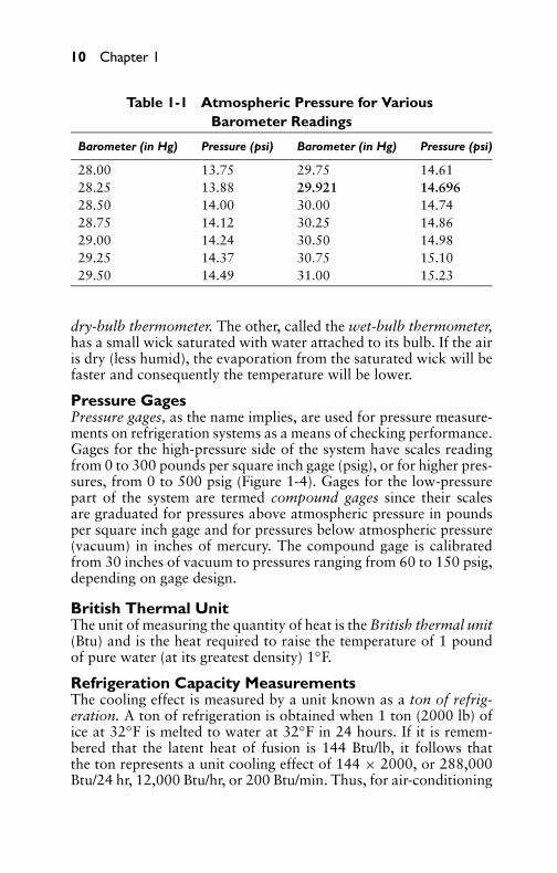
Standard atmospheric pressure at sea level is 29.921 inches ofmercury. Most of the pressure gages used in engineering calculationsindicate gage pressure, or pounds per square inch (psi). Barometerreadings may be converted into gage pressure by multiplying inchesof mercury by 0.49116. Thus, if the barometer reads 29.921 inches,the corresponding gage pressure equals 0.49116 × 29.921, or14.696 psi. Table 1-1 is a convenient conversion table based on thestandard atmosphere, which, by definition, equals 29.921 inches ofmercury (in Hg), or 14.696 psi.
Sling PsychrometerRelative humidity is measured by an instrument known as the slingpsychrometer, which uses two mercury thermometers mounted sideby side (see Figure 1-3). One of the thermometers is the sametype used to measure the temperature of the air; it is called the
P1: GDZ/FFX P2: GDZ/FFX QC: GDZ/FFX T1: GDZ
GB076-01 GB076-Miller-Sample July 14, 2004 22:26 Char Count= 0
10 Chapter 1
Table 1-1 Atmospheric Pressure for VariousBarometer Readings
Barometer (in Hg) Pressure (psi) Barometer (in Hg) Pressure (psi)
28.00 13.75 29.75 14.6128.25 13.88 29.921 14.69628.50 14.00 30.00 14.7428.75 14.12 30.25 14.8629.00 14.24 30.50 14.9829.25 14.37 30.75 15.1029.50 14.49 31.00 15.23
dry-bulb thermometer. The other, called the wet-bulb thermometer,has a small wick saturated with water attached to its bulb. If the airis dry (less humid), the evaporation from the saturated wick will befaster and consequently the temperature will be lower.
Pressure GagesPressure gages, as the name implies, are used for pressure measure-ments on refrigeration systems as a means of checking performance.Gages for the high-pressure side of the system have scales readingfrom 0 to 300 pounds per square inch gage (psig), or for higher pres-sures, from 0 to 500 psig (Figure 1-4). Gages for the low-pressurepart of the system are termed compound gages since their scalesare graduated for pressures above atmospheric pressure in poundsper square inch gage and for pressures below atmospheric pressure(vacuum) in inches of mercury. The compound gage is calibratedfrom 30 inches of vacuum to pressures ranging from 60 to 150 psig,depending on gage design.
British Thermal UnitThe unit of measuring the quantity of heat is the British thermal unit(Btu) and is the heat required to raise the temperature of 1 poundof pure water (at its greatest density) 1◦F.
Refrigeration Capacity MeasurementsThe cooling effect is measured by a unit known as a ton of refrig-eration. A ton of refrigeration is obtained when 1 ton (2000 lb) ofice at 32◦F is melted to water at 32◦F in 24 hours. If it is remem-bered that the latent heat of fusion is 144 Btu/lb, it follows thatthe ton represents a unit cooling effect of 144 × 2000, or 288,000Btu/24 hr, 12,000 Btu/hr, or 200 Btu/min. Thus, for air-conditioning

P1: GDZ/FFX P2: GDZ/FFX QC: GDZ/FFX T1: GDZ
GB076-01 GB076-Miller-Sample July 14, 2004 22:26 Char Count= 0
Air-Conditioning Fundamentals 11
10
1040
5060
7080
9010
100
4050
6070
8090
100
10
PSYC
HROM
ETER
SLI
DE R
ULE
7060
5040
3020
010
2030
4050
6070
8090
7060
3040
10
Figure 1-3 Sling psychrometer. Note the thermometers plus a sliderule for obtaining relative humidity.
120 110 500
450
400
350
300250
120110
160
100
90
80
200
130140
150
200
150
100
50
0
100
90
80
706050
40
30
20
10
010 20
9590
80
70
6050
40
30
20
100−10
−20−40
−50−30
−10
010
20 3040
60
90
150140130
120
110100
8060
4020
VAC 250
MARSH MARSH
R-28
R-12
R-28
R-12
Figure 1-4 Compound (left) and high-pressure (right) gages.(Courtesy Marsh Instrument Co., Inc.)
P1: GDZ/FFX P2: GDZ/FFX QC: GDZ/FFX T1: GDZ
GB076-01 GB076-Miller-Sample July 14, 2004 22:26 Char Count= 0
12 Chapter 1
calculation, the size of the required condensing unit (expressed intons) can be obtained by dividing the heat gain of the structure(expressed in Btu/hr) by 12,000. The foregoing may be written asfollows:
Refrigeration (in tons) = Btu/hr heat gain12,000
SummaryFactors affecting both physical and chemical conditions of the atmo-sphere are temperature, humidity, motion, distribution, dust, bac-teria, odor, and toxic gases. Air is a mixture of two gases: oxygenand nitrogen. There are still other gases in the air, such as carbondioxide, carbon monoxide, ozone, and neon in small quantities. Theair must be constantly moving to carry away the moisture and heat.
Air filters are used to eliminate particles of dirt or dust carried inthe air that are detrimental to health and comfort. Water filters areeffective in removing dust and some fumes and smoke, but carbonand soot are not removed by this method. Dry filters and electronicfilters make it possible to clean the air of most harmful dust andpollen.
Heat is an active form of energy much the same as mechanicaland electrical energy. Heat is transferred by three methods: con-duction, convection, and radiation. Conduction means the flow ofheat through a solid substance (such as iron). The transfer of heat byconvection means the carrying of heat by air rising from a heated sur-face. Radiation takes place in the absence of matter, as in the passageof heat through the vacuum inside the bulb of an incandescent lamp.
Sensible heat is a form of heat that causes a change in the tem-perature of a substance. Specific heat is the Btu required to raisethe temperature of one pound of substance one degree Fahrenheit.Latent heat is the form of heat that changes the physical state of asubstance, such as solid to liquid or liquid to a vapor. Latent heatof fusion is the point at which a substance changes from a solid toa liquid or from a liquid to a solid.
Latent heat of evaporation is the point at which a substancechanges from a liquid to a vapor or from a vapor back to a liq-uid. It takes 970 Btu to change 1 lb of pure water at 212◦F to steamwhen atmospheric pressure is at sea level. Superheat is sensible heatabsorbed by a vapor or gas not in contact with its liquid and con-sequently does not follow the temperature–pressure relationship.
A thermometer is an instrument used for determining the temper-ature of a body or space. The barometer is an instrument used for

P1: GDZ/FFX P2: GDZ/FFX QC: GDZ/FFX T1: GDZ
GB076-01 GB076-Miller-Sample July 14, 2004 22:26 Char Count= 0
Air-Conditioning Fundamentals 13
measuring the atmospheric pressure. Standard atmospheric pressureat sea level is 29.921 in Hg, or 14.696 psi.
Review Questions1. Name the three most important factors that affect human
health and comfort.2. What factors besides heating and cooling are necessary in an
air-conditioning system?3. What are the chemical constituents of air?4. Why is air movement a necessary part of air conditioning?5. What are the devices used for cleaning and filtering air?6. What are the three principal methods by which heat may be
transferred through space?7. If the specific heat of water is taken as 1.00, what is the specific
heat of iron?8. How does latent heat affect the change of state in various
substances?9. What is meant by “the latent heat of evaporation”?
10. What is superheat?11. State the relations between pressure, temperature, and volume
for a given weight of gas.12. How many Btus are required to convert 1 pound of water at
32◦F to 1 pound of ice at the same temperature?13. Define the law of conservation of matter.14. Define Boyle’s law.15. State the relations between the various temperature scales.16. What instrument is commonly used for measurement of
atmospheric pressure?17. State the relations between absolute and gage pressure.18. What is a British thermal unit?19. What is a ton of refrigeration, and what is the Btu equivalent?20. What is the old name used for degrees Celsius?

P1: GDZ/FFX P2: GDZ/FFX QC: GDZ/FFX T1: GDZ
GB076-01 GB076-Miller-Sample July 14, 2004 22:26 Char Count= 0
14

P1: GDZ/FFX P2: GDZ/FFX QC: GDZ/FFX T1: GDZ
GB076-02 GB076-Miller-Sample July 14, 2004 20:6 Char Count= 0
Chapter 2PsychrometryPsychrometry is that branch of physics relating to the measurementor determination of atmospheric conditions, particularly regardingthe moisture mixed with air. In calculations of all air-conditioningsituations, you should understand that the dry air and water vaporcomposing the atmosphere are separate entities, each with its owncharacteristics. This water vapor is not dissolved in the air in thesense that it loses its own individuality, but merely serves to moistenthe air.
Air and Water-Vapor MixturesWater vapor is a gaseous form of water at a temperature belowthe boiling point of water. It is the most variable constituent of theatmosphere. At certain temperatures and barometric pressures, it isextremely unstable in either gaseous or liquid form. This is evidentby the formation and disappearance of clouds and fog. Water vaporconstitutes about 3 percent of the total air by volume in hot, humidweather, and about 1/5 of 1 percent of total air by volume in dry,cold weather. Water vapor is actually steam at very low pressure.Hence, its properties are those of steam at low temperatures, and itsactions are comparable to steam.
Humidifying and DehumidifyingThe air becomes humidified when moisture is added to it and is de-humidified when moisture is removed. Perhaps it may seem strangethat the addition of moisture to air and the removal of moisture fromair are two of the six important essentials of proper air conditioning.It does seem odd that the amount of moisture in the air of a roomshould have any effect on the personal comfort of the occupant. Anexcess or deficiency of moisture, however, does have a very notice-able effect that will immediately become apparent once the meaningof the somewhat mysterious term relative humidity is understood.
Relative HumidityRelative humidity may be defined as the ratio of the quantity ofvapor actually present in the air to the greatest amount possible atany given temperature. It follows that the relative humidity of airat any given temperature can be obtained merely by dividing theamount of moisture actually in the air by the amount of moisturethat the air can hold at that temperature, and then multiplying theresult by 100 to get the percentage factor.
15
P1: GDZ/FFX P2: GDZ/FFX QC: GDZ/FFX T1: GDZ
GB076-02 GB076-Miller-Sample July 14, 2004 20:6 Char Count= 0
16 Chapter 2
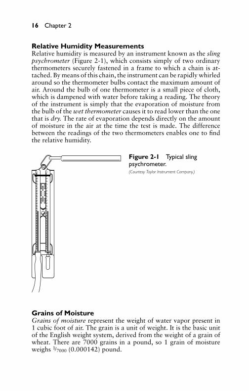
Relative Humidity MeasurementsRelative humidity is measured by an instrument known as the slingpsychrometer (Figure 2-1), which consists simply of two ordinarythermometers securely fastened in a frame to which a chain is at-tached. By means of this chain, the instrument can be rapidly whirledaround so the thermometer bulbs contact the maximum amount ofair. Around the bulb of one thermometer is a small piece of cloth,which is dampened with water before taking a reading. The theoryof the instrument is simply that the evaporation of moisture fromthe bulb of the wet thermometer causes it to read lower than the onethat is dry. The rate of evaporation depends directly on the amountof moisture in the air at the time the test is made. The differencebetween the readings of the two thermometers enables one to findthe relative humidity.
Figure 2-1 Typical slingpsychrometer.(Courtesy Taylor Instrument Company.)
Grains of MoistureGrains of moisture represent the weight of water vapor present in1 cubic foot of air. The grain is a unit of weight. It is the basic unitof the English weight system, derived from the weight of a grain ofwheat. There are 7000 grains in a pound, so 1 grain of moistureweighs 1/7000 (0.000142) pound.

P1: GDZ/FFX P2: GDZ/FFX QC: GDZ/FFX T1: GDZ
GB076-02 GB076-Miller-Sample July 14, 2004 20:6 Char Count= 0
Psychrometry 17
Specific VolumeSpecific volume is the number of cubic feet of moist air requiredto contain 1 pound of dry air molecules. Specific volume is the re-ciprocal of the specific gravity. It is equal to the number of cubiccentimeters occupied by 1 gram of a substance when the specificgravity is referred to water at 40◦C (39.2◦F) as a standard.
Dew-Point TemperatureThe saturation temperature for any given quantity of water vaporin the atmosphere is known as the dew point. By definition, fora given atmospheric pressure, the dew point is the temperature ofsaturation at which moisture begins to change into the form of tinywater droplets or dew.
Effective TemperatureAs applied to air conditioning, the effective temperature is an empir-ically determined index of the degree of warmth or cold as apparentto the human body. It takes into account the temperature, moisturecontent, and motion of the surrounding air. Effective temperaturesare not strictly a degree of heat in the same sense that dry-bulb tem-peratures are. For example, the effective temperature can be loweredby increasing the rate of airflow even though wet- and dry-bulb tem-peratures remain constant. For space cooling and heating, however,the air-movement factor is considered a constant at approximately20 ft/min. Under this condition, effective temperature is determinedby the wet- and dry-bulb thermometer readings only.
Dry-Bulb TemperatureAn ordinary thermometer is used to measure dry-bulb temperature.Two types of liquid are used in thermometers: colored alcohol andmercury. The alcohol thermometer is more common because it isless expensive and can measure the normal range of air temperature.Since mercury freezes at approximately −38◦F, mercury thermome-ters are not practical for measuring extremely low temperatures.
Wet-Bulb TemperatureWet-bulb temperature is the temperature at which the air becomessaturated if moisture is added to it without the addition or sub-traction of heat. Thus, if the bulb of an ordinary thermometer issurrounded with a moistened wick, placed in a current of air, andsuperheated with water vapor, the reading obtained will be at somepoint below the dry-bulb temperature. The minimum reading thusobtained is the wet-bulb temperature of the air.

P1: GDZ/FFX P2: GDZ/FFX QC: GDZ/FFX T1: GDZ
GB076-02 GB076-Miller-Sample July 14, 2004 20:6 Char Count= 0
18 Chapter 2
Wet-Bulb DepressionSince outdoor summer air is rarely fully saturated, there is normally aconsiderable difference between its dry- and wet-bulb temperatures.The difference between the two temperatures is called the wet-bulbdepression. For example, if the dry-bulb temperature reading is 80and the corresponding wet-bulb temperature is 65, the wet-bulbdepression is 80 − 65, or 15.
Temperature-Humidity IndexThe temperature-humidity index numerically describes the humandiscomfort resulting from temperature and moisture. It is computedby adding dry- and wet-bulb temperature readings, multiplyingthe sum by 0.4, and adding 15. Summer estimates indicate about10 percent of the populace are uncomfortable before the indexpasses 70, more than 50 percent are uncomfortable after it passes 75,and almost all are uncomfortable at 80 or above.
Total Heat ContentTotal heat content is the amount of heat energy stored in the gaseousair and water vapor, measured in British thermal units (Btu). All thedifferent methods of treating air can be pictured on the psychromet-ric chart. The magnitude of the changes required can be determinedby plotting the conditions of the air entering and leaving the appa-ratus, and then connecting the two points by a straight line.
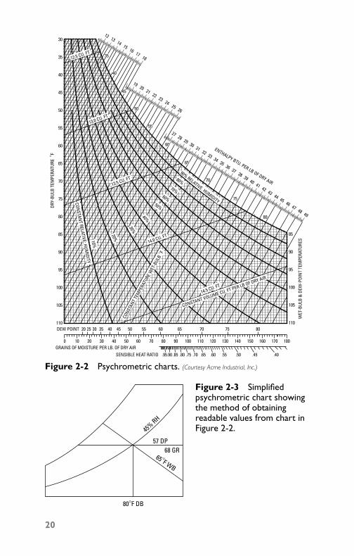
Psychrometric ChartsA psychrometric chart is a graphical representation of the funda-mental mathematical relationship dealing with the thermodynamicproperties of moist air. The various charts shown in the figures on thefollowing pages will be found valuable in making air-conditioningcalculations. The chart readings can be obtained for dry-bulb,wet-bulb, and dew-point temperatures and other heat-treatmentproperties.
Three basic formulas can be utilized to determine (1) the totalheat to be removed from both the gases and water vapor; (2) thesensible heat removed from the air only; and (3) the latent heatremoved in condensing the water vapor:
Total heat = ft3/min × 4.5 (h1 − h2) = Btu/hrSensible heat = ft3/min × 1.08 (DB1 − DB2) = Btu/hrLatent heat = ft3/min × 68 (WB1 − WB2) = Btu/hr

P1: GDZ/FFX P2: GDZ/FFX QC: GDZ/FFX T1: GDZ
GB076-02 GB076-Miller-Sample July 14, 2004 20:6 Char Count= 0
Psychrometry 19
where the following is true:
h1 = total heat for entering air (Btu/lb)h2 = total heat for leaving air (Btu/lb)DB1 = entering air for dry-bulb temperatureDB2 = leaving air for dry-bulb temperatureWB1 = entering air for wet-bulb temperatureWB2 = leaving air for wet-bulb temperature
Most air-conditioning calculations are made assuming normalsea-level pressure and standard temperatures, but occasionally thealtitude or high-temperature industrial applications will requireconverting from standard conditions to those actually present. UseTable 1-1 (Chapter 1) to obtain corrected atmospheric pressure.
Psychrometric Chart InstructionsIn Figure 2-2, note the point encircled in the center of the chart,which represents a condition of 80◦F dry-bulb temperature and50.9 percent relative humidity. The lines on the chart sloping up-ward to the left represent constant wet-bulb temperature, which,in this case, is 67◦F. The moisture content of the encircled point is78 grains per pound of dry air. The total heat in Btu per pound, asnoted, is scaled at the extreme right. The heat removed in the coolingof air can be obtained by finding the difference in the total heat cor-responding to the wet-bulb temperature at the beginning and thefinal conditions. For example, if air is to be cooled from a conditionof 65◦F dry-bulb temperature and 60 percent relative humidity, thetotal heat (from Figure 2-2) is 24.5 Btu/lb of dry air.
When calculating the amount of refrigeration required for a par-ticular job, it is generally necessary to make allowances for the var-ious conditions, such as heat losses caused by leakage (infiltration),the heating effect caused by electrical apparatus, and body heat frompersons, which exists in theaters and auditoriums where a large num-ber of persons are gathered (Figure 2-3).
Calculation ExamplesIt is now possible to proceed with illustrative examples of a generalnature so that the solutions can be used on other problems if otherdetails are known.
P1: GDZ/FFX P2: GDZ/FFX QC: GDZ/FFX T1: GDZ
GB076-02 GB076-Miller-Sample July 14, 2004 20:6 Char Count= 0
27 28 29 30 31 32 33 34 35 36 37 38 39 40 41 42 43 44 45 46 47 48 49
19 20 21 22 23 2425 26
12 13 14 15 16 17 18
30
35
40
45
50
55
60
65
70
75
80
85
90
95
100
105
110
12.5 CU. FT
13.0 CU. FT
13.5 CU. FT
14.0 CU. FT
90% RELATIVE. HUMIDITY
80%70%
60%50%
40%
30%
20%10%
14.5 CU. FT
CONSTANT VOLUME CU. FT PER LB OF DRY AIR
CONS
TANT
TEM
PERA
TURE
WET
-BUL
B ° F
CONSTAN
T RELATIVE; HUMIDITY
85
90
95
100
105
110
WET
-BUL
B &
DEW
-POI
NT
TEM
PERA
TURE
S
DRY-
BULB
TEM
PERA
TURE
°F
ENTHALPY BTU. PER LB OF DRY AIR
DEW POINT 20
0 10 20 30 40 50 60 70 80 90 100 110
.95SENSIBLE HEAT RATIOGRAINS OF MOISTURE PER LB. OF DRY AIR
.90 .85 .80 .75 .70 .65 .60 .55 .50 .45 .40
120 130 140 150 160 170 180
25 30 35 40 45 50 55 60 65 70 75 80
35
40
45
50
55
60
65
70
75
80
Figure 2-2 Psychrometric charts. (Courtesy Acme Industrial, Inc.)
80°F DB
65°F WB
45% RH
57 DP68 GR
Figure 2-3 Simplifiedpsychrometric chart showingthe method of obtainingreadable values from chart inFigure 2-2.
20

P1: GDZ/FFX P2: GDZ/FFX QC: GDZ/FFX T1: GDZ
GB076-02 GB076-Miller-Sample July 14, 2004 20:6 Char Count= 0
Psychrometry 21
Example 1Given 80◦F dry-bulb and 65◦F wet-bulb temperature, find the dewpoint, relative humidity, and grains of moisture per pound of dry air.
SolutionFigure 2-4 shows the solution schematically. The intersection onthe chart of the two temperature conditions shows a dew point of57.0 and a relative humidity of 45 percent. There are 68 grains ofmoisture/lb of dry air.
DRY-BULBTEMPERATURE
WET
-BULB
TEM
PERA
TURE GRAIN
SDEW
POINT
HUMIDITY
VOLUME
TOTAL HEAT PER
POUND OF DRY AIR
SENSIBLE HEAT RATIO
SATURATIONLINE
RELATIVE
Figure 2-4 Schematic solutionfor Example 1.
Example 2Find the total heat load for cooling 6000 ft3/min of air entering at83◦F dry-bulb and 70◦F wet-bulb, and leaving at 60◦F dry-bulb and58◦F wet-bulb.
SolutionFigure 2-5 shows the schematic solution. Locate the entering andleaving conditions on chart. Read the total heat of 34.1 Btu/lb forentering air and 25.2 Btu/lb for leaving air. The total heat may beobtained by substitution of values:
Total Heat = ft3/min × 4.5(h1 − h2)
= 6000 × 4.5(34.1 − 25.2)
= 240,300 Btu/hr (approx.)

P1: GDZ/FFX P2: GDZ/FFX QC: GDZ/FFX T1: GDZ
GB076-02 GB076-Miller-Sample July 14, 2004 20:6 Char Count= 0
22 Chapter 2
60°F DB
WB
WB58°F
70°F
83°F DB
25.2 h 2
34.1 h 1
Figure 2-5 Schematicsolution for Example 2.
Example 3Find the apparatus dew point for air entering at 82◦F dry-bulb and68◦F wet-bulb, and leaving at 59◦F dry-bulb and 57◦F wet-bulb.
SolutionFigure 2-6 shows the schematic solution. By extending the line toconnect the entering and leaving conditions of air to the saturationcurve, the apparatus dew point or average surface temperature ofthe coil can be found. Following this procedure, the apparatus dewpoint is 54.5.
57°F WB
54.5 A DB
59°F DB 82°F DB
68°F WB
Figure 2-6 Schematicsolution for Example 3.
Example 4Assume that air is entering at 81◦F dry-bulb and 69◦F wet-bulb, andleaving at 56◦F dry-bulb and 54◦F wet-bulb. If the total heat loadis 460,000 Btu/hr, what is the sensible heat factor?

P1: GDZ/FFX P2: GDZ/FFX QC: GDZ/FFX T1: GDZ
GB076-02 GB076-Miller-Sample July 14, 2004 20:6 Char Count= 0
Psychrometry 23
SolutionFigure 2-7 shows the schematic solution. By using the sensible-heatfactor (as noted on the chart), the ratio of the sensible heat to thetotal load can easily be found. First, locate the entering and leav-ing conditions and draw a straight line connecting the two pointson the chart. Next, locate the sensible-heat ratio reference pointon the chart for 81◦F dry-bulb and 69◦F wet-bulb. Draw a linethrough the reference point parallel with the line representing theentering and leaving conditions. Extend the line and read 0.54sensible-heat factor. The sensible heat load equals 0.54 × 460,000,or 248,400 Btu/hr.
54°F WB
56°F DB 81°F DB
69°F WB
0.54
SEN
SIBL
E HE
AT F
ACTO
R Figure 2-7 Schematicsolution for Example 4.
Example 5Find the dry-bulb and wet-bulb temperatures for an air mixture of7500 cubic feet per minute (ft3/min) of inside air at 76◦F dry-bulband 63◦F wet-bulb, mixed with 2500 ft3/min of outside air enteringat 95◦F dry-bulb and 75◦F wet-bulb.
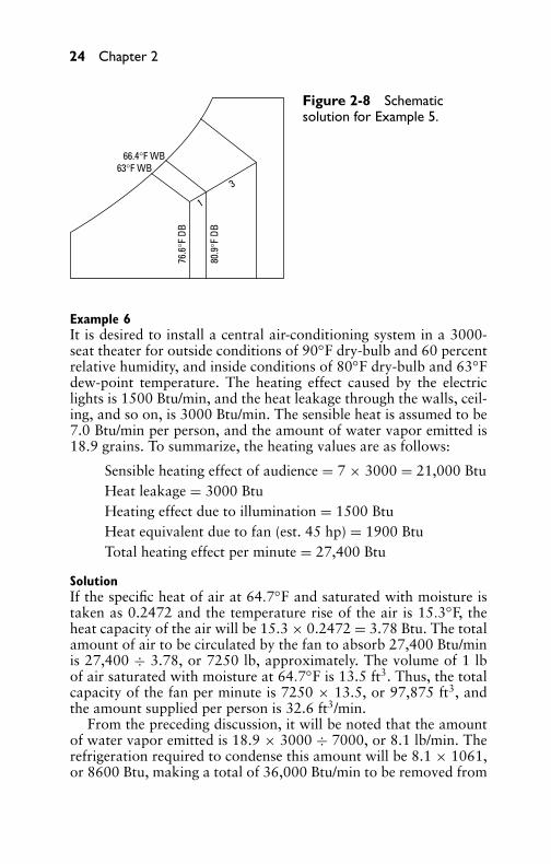
SolutionWith reference to the schematic solution in Figure 2-8, the followingchart readings will indicate the procedure. Locate the conditions forinside and outside air on the chart. Draw a line connecting the twopoints. The ratio of inside to outside air is 2:1. Divide the line intofour equal parts. Count up one equal part of the line from the insideair condition. This point represents the conditions of the air mixture,which are 80.9◦F dry-bulb and 66.4◦F wet-bulb.
P1: GDZ/FFX P2: GDZ/FFX QC: GDZ/FFX T1: GDZ
GB076-02 GB076-Miller-Sample July 14, 2004 20:6 Char Count= 0
24 Chapter 2
66.4°F WB63°F WB
76.6
°F D
B
80.9
°F D
B1
3
Figure 2-8 Schematicsolution for Example 5.
Example 6It is desired to install a central air-conditioning system in a 3000-seat theater for outside conditions of 90◦F dry-bulb and 60 percentrelative humidity, and inside conditions of 80◦F dry-bulb and 63◦Fdew-point temperature. The heating effect caused by the electriclights is 1500 Btu/min, and the heat leakage through the walls, ceil-ing, and so on, is 3000 Btu/min. The sensible heat is assumed to be7.0 Btu/min per person, and the amount of water vapor emitted is18.9 grains. To summarize, the heating values are as follows:
Sensible heating effect of audience = 7 × 3000 = 21,000 BtuHeat leakage = 3000 BtuHeating effect due to illumination = 1500 BtuHeat equivalent due to fan (est. 45 hp) = 1900 BtuTotal heating effect per minute = 27,400 Btu
SolutionIf the specific heat of air at 64.7◦F and saturated with moisture istaken as 0.2472 and the temperature rise of the air is 15.3◦F, theheat capacity of the air will be 15.3 × 0.2472 = 3.78 Btu. The totalamount of air to be circulated by the fan to absorb 27,400 Btu/minis 27,400 ÷ 3.78, or 7250 lb, approximately. The volume of 1 lbof air saturated with moisture at 64.7◦F is 13.5 ft3. Thus, the totalcapacity of the fan per minute is 7250 × 13.5, or 97,875 ft3, andthe amount supplied per person is 32.6 ft3/min.
From the preceding discussion, it will be noted that the amountof water vapor emitted is 18.9 × 3000 ÷ 7000, or 8.1 lb/min. Therefrigeration required to condense this amount will be 8.1 × 1061,or 8600 Btu, making a total of 36,000 Btu/min to be removed from
P1: GDZ/FFX P2: GDZ/FFX QC: GDZ/FFX T1: GDZ
GB076-02 GB076-Miller-Sample July 14, 2004 20:6 Char Count= 0
Psychrometry 25
the air if all of it is to be recirculated. If only one-half is to be recir-culated and the other half is to be exhausted into the atmosphere,there will be 18,000 Btu/min of refrigeration required for the air tobe recirculated. The fresh air will enter the spray chamber at 90◦Fand 60 percent relative humidity, which corresponds to a dew-pointtemperature of 74.2 and a moisture content of 127 grains/lb of dryair. The refrigeration required to cool this air to the temperature ofthe spray chamber, taken from the total heat curve, is 41.3 – 29.3,or 12.0 Btu/lb, and the total refrigeration is 7250 ÷ 2 × 12.0, or43,500 Btu. The total demand on the refrigeration equipment be-comes 43,500 + 18,000, or 61,500 Btu. Adding 5 percent for safety,the amount becomes 64,600 Btu/min, or 323.0 tons of refrigeration.
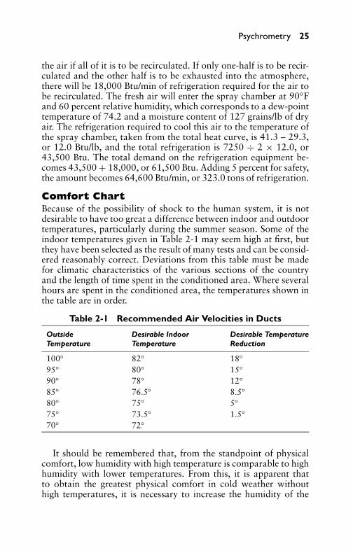
Comfort ChartBecause of the possibility of shock to the human system, it is notdesirable to have too great a difference between indoor and outdoortemperatures, particularly during the summer season. Some of theindoor temperatures given in Table 2-1 may seem high at first, butthey have been selected as the result of many tests and can be consid-ered reasonably correct. Deviations from this table must be madefor climatic characteristics of the various sections of the countryand the length of time spent in the conditioned area. Where severalhours are spent in the conditioned area, the temperatures shown inthe table are in order.
Table 2-1 Recommended Air Velocities in Ducts
Outside Desirable Indoor Desirable TemperatureTemperature Temperature Reduction
100◦ 82◦ 18◦
95◦ 80◦ 15◦
90◦ 78◦ 12◦
85◦ 76.5◦ 8.5◦
80◦ 75◦ 5◦
75◦ 73.5◦ 1.5◦
70◦ 72◦
It should be remembered that, from the standpoint of physicalcomfort, low humidity with high temperature is comparable to highhumidity with lower temperatures. From this, it is apparent thatto obtain the greatest physical comfort in cold weather withouthigh temperatures, it is necessary to increase the humidity of the

P1: GDZ/FFX P2: GDZ/FFX QC: GDZ/FFX T1: GDZ
GB076-02 GB076-Miller-Sample July 14, 2004 20:6 Char Count= 0
26 Chapter 2
room conditioned. It also explains why persons in some parts of thecountry do not suffer unduly even though the outside air tempera-tures are 120◦F or more but with low relative humidity.
50
50
55
60
65
65
60
55
75
80
85
90%
1009080
7060
4030
2010
1020
3040
5060
7080
90100
80%
70%
60%
50%
40%
30%
20%
10%
70
70
75
40
50
60
70
80
90
60 70 80 90 100
DRY-BULB TEMPERATURE °F
WET
-BUL
B TE
MPE
RATU
RE ° F
WINTER
COMFORT
ZONE
SUMMER
COMFORT
ZONE
AVERAGE WINTER COMFORT ZONE
AVERAGE SUMMER COMFORT ZONEOPTIMUM WINTER COMFORT LINE
OPTIMUM SUMMER COMFORT LINE
RELATIVE HUMIDITY
PERCENT OFSUBJECTS FEELING
COMFORTABLE
55° E
FFEC
T. TE
MP.
LIN
E
PERCENT OFSUBJECTSFEELINGCOMFORTABLE
AIR MOVEMENT OR TURBULENCE 15 TO 25 FT PER MIN.
50
Figure 2-9 Comfort charts. (Courtesy American Society of Heating & Ventilating Engineers.)
With reference to the comfort chart in Figure 2-9, it should benoted that both summer and winter comfort zones apply to inhab-itants of the United States only. Application of the winter comfortline is further limited to rooms heated by central systems of theconvection type. The line does not apply to rooms heated by radi-ant methods. Application of the summer comfort line is limited tohomes, offices, and so on, where the occupants become fully adaptedto the artificial air conditions. The line does not apply to theaters,department stores, and so on, where the exposure is less than three

P1: GDZ/FFX P2: GDZ/FFX QC: GDZ/FFX T1: GDZ
GB076-02 GB076-Miller-Sample July 14, 2004 20:6 Char Count= 0
Psychrometry 27
hours. The optimum comfort line shown pertains to Pittsburgh andother cities in the northern portion of the United States and South-ern Canada at elevations not in excess of 1000 feet above sea level.An increase of approximately 1◦F should be made for every 5◦ re-duction in north latitude.
SummaryWater vapor is a gaseous form of water at a temperature belowits boiling point. At certain temperatures and barometric pressures,water is extremely unstable in either gaseous or liquid form. Theair becomes humidified when moisture is added and is dehumidifiedwhen moisture is removed. An excess or deficiency of moisture hasa very noticeable effect on comfort.
Relative humidity may be defined as the ratio of the quantity ofmoisture actually present in the air to the greatest amount possibleat any given temperature. The relative humidity of the air at anygiven temperature can be obtained merely by dividing the amountof moisture actually in the air by the amount of moisture the aircan hold at that temperature. Relative humidity is measured by aninstrument called the sling psychrometer.
Grains of moisture is the weight of water vapor present in 1 cubicfoot of air. A grain is the basic unit of the English weight system, and7000 grains = 1 lb. One grain of moisture weighs 1/7000 (0.000142)pound.
The saturation temperature for any given quantity of water va-por in the atmosphere is known as the dew point. For a given at-mospheric pressure, it is the temperature at which moisture beginsto change into the form of tiny water droplets or dew. Total heatcontent is the amount of heat energy stored in the gaseous air andwater vapor, and is measured in British thermal units (Btu).
When calculating the amount of refrigeration required for a par-ticular job, it is generally necessary to make allowances for variousconditions, such as heat loss from infiltration, heat from electricalapparatus, and body heat. Most air-conditioning calculations aremade assuming sea-level pressure and standard temperature.
Review Questions1. What is meant by the term psychrometry?2. State the amount of water vapor present in the air during hot,
humid weather.3. What is the purpose of humidification and dehumidification
of air?

P1: GDZ/FFX P2: GDZ/FFX QC: GDZ/FFX T1: GDZ
GB076-02 GB076-Miller-Sample July 14, 2004 20:6 Char Count= 0
28 Chapter 2
4. What is meant by the term relative humidity?5. How is relative humidity measured?6. Define dew point, effective temperature, and dry- and wet-bulb
temperature.7. What is meant by wet-bulb depression?8. What is the function of the psychrometric chart in making
air-conditioning calculations?9. Describe the construction and use of the sling psychrometer.
10. If it is assumed that the dry- and wet-bulb temperatures register80◦F and 65◦F, respectively, what is the temperature humidityindex?

P1: GDZ/FFX P2: GDZ/FFX QC: GDZ/FFX T1: GDZ
GB076-03 GB076-Miller-Sample July 15, 2004 8:54 Char Count= 0
Chapter 3Heat LeakageThe thermal properties of building materials affect the design of theair-conditioning and heating systems. The rate of heat flow throughwalls, floors, and ceilings is usually the basis for calculating the heatand/or cooling load required for a particular building or space.
In addition, consideration must be given to air leakage that takesplace through various apertures, which must be properly evaluated.This air leakage takes place through cracks around windows anddoors, through walls, fireplaces, and chimneys. Although the leak-age or air infiltration through fireplaces and chimneys may be con-siderable, it is usually neglected since the dampers should be closedduring periods of extremely hot weather.
In this connection, you should note that, because of the numer-ous variables affecting air-conditioning loads, it is often difficult tocalculate precisely the required size of an air-conditioning unit for aparticular building or space. This will easily be realized when con-sideration is given to the fact that most of the components of thecooling load vary greatly during a 24-hour period. Economic con-sideration should thus be the determining factor in the selection ofequipment for cooling-season operation in comfort air conditioning,since available weather and other necessary data vary for differentlocations.
Heat leakage is always given in Btu per hour per degree Fahren-heit temperature difference per square foot of exposed surface(Btu/ft2/hr/◦F). Prior to designing an air-conditioning system, an es-timate must be made of the maximum probable heat loss for eachroom or space to be cooled. Therefore, before attempting to placeeven a small room cooler into service, check the walls and determinejust what size unit will do a good job of cooling and dehumidifying.
Heat losses may be divided into two groups:� Losses through confining walls, floors, ceilings, glass, or other
surfaces� Infiltration losses caused by leaks through cracks and crevices
around doors and windows
The heat leakage through walls, floors, and ceilings can be deter-mined by means of a formula and depends on the type and thicknessof the insulating material used. The formula for heat leakage is asfollows:
H = K A (t1 − t2)
29

P1: GDZ/FFX P2: GDZ/FFX QC: GDZ/FFX T1: GDZ
GB076-03 GB076-Miller-Sample July 15, 2004 8:54 Char Count= 0
30 Chapter 3
where the following is true:
H = the heat required
K = heat-transfer coefficient, Btu/ft2/hr/◦F
A = area, ft2
t1 − t2 = temperature gradient through wall, ◦F
Calculation ExamplesA real-world example shows how this formula works.
ExampleCalculate the heat leakage through an 8-inch brick wall having anarea of 200 ft2 if the inside temperature is 70◦F and the outsidetemperature is 10◦F.
SolutionIf it is assumed that the heat-transfer coefficient of a plain brick wallis 0.50, substitution of values in the foregoing equation will be asfollows:
H = 0.50 × 200 (70 − 10) = 6000 Btu
The heat leakage through floors, ceilings, and roofs may beestimated in the same manner. The K (heat-transfer coefficient)depends on the construction and particular insulating materialsused.
Reference TablesTables 3-1 to 3-20 cover almost every type and combination of walls,floors, and ceilings encountered in the field. Partition walls are alsoincluded so that these may be estimated for heat leakage. Althoughthe K values given in the tables do not agree entirely with the datagiven in various handbooks, they will give sufficiently close valuesfor adaptation since, in most instances, only approximate values canbe obtained. In making use of the data, remember that the outsidearea is used as a basis for estimating. Ceiling and floor constructionmust also be determined, and, in some situations, the four walls ofthe room may not be of the same construction (since one or moreof the walls may be partitions).

P1: GDZ/FFX P2: GDZ/FFX QC: GDZ/FFX T1: GDZ
GB076-03 GB076-Miller-Sample July 15, 2004 8:54 Char Count= 0
Heat Leakage 31
X
YK = X + Y
X = WALL
Y = INTERIOR CONSTRUCTION
Table 3-1 Concrete Wall (No Exterior Finish)—Valuesof K in Btu/ ft2/hr/1◦F
Thickness (X)
6 8 10 12 16Wall Construction (Y) inches inches inches inches inches
Plain wall—no interior finish 0.58 0.51 0.46 0.41 0.341/2-inch plaster—direct on concrete 0.52 0.46 0.42 0.38 0.321/2-inch plaster on wood lath,
furred0.31 0.29 0.26 0.24 0.22
3/4-inch plaster on metal lath,furred
0.34 0.32 0.29 0.27 0.24
1/2-inch plaster on 3/8-inchplasterboard, furred
0.32 0.30 0.27 0.25 0.22
1/2-inch plaster on 1/2-inch boardinsulation, furred
0.21 0.20 0.19 0.18 0.17
1/2-inch plaster on 1-inchcorkboard, set in 1/2-inch cement
0.16 0.15 0.14 0.14 0.13
1/2-inch plaster on 11/2-inchcorkboard, set in 1/2-inch cement
0.15 0.14 0.14 0.13 0.12
1/2-inch plaster on 2-inchcorkboard, set in 1/2-inch cement
0.13 0.12 0.11 0.10 0.09
1/2-inch plaster on wood lath on2-inch fur, 15/8-inch gypsum fill
0.20 0.19 0.18 0.17 0.16
P1: GDZ/FFX P2: GDZ/FFX QC: GDZ/FFX T1: GDZ
GB076-03 GB076-Miller-Sample July 15, 2004 8:54 Char Count= 0
32 Chapter 3
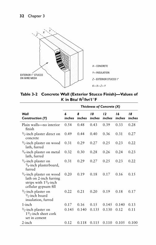
EXTERIOR 1” STUCCO ON WIRE MESH
ZX Y
X = CONCRETE
Y = INSULATION
Z = EXTERIOR STUCCO 1”
K = X + Z + Y
Table 3-2 Concrete Wall (Exterior Stucco Finish)—Values ofK in Btu/ ft2/hr/1◦F
Thickness of Concrete (X)
Wall 6 8 10 12 16 18Construction (Y) inches inches inches inches inches inches
Plain walls—no interiorfinish
0.54 0.48 0.43 0.39 0.33 0.28
1/2-inch plaster direct onconcrete
0.49 0.44 0.40 0.36 0.31 0.27
1/2-inch plaster on woodlath, furred
0.31 0.29 0.27 0.25 0.23 0.22
3/4-inch plaster on metallath, furred
0.32 0.30 0.28 0.26 0.24 0.23
1/2-inch plaster on3/8-inch plasterboard,furred
0.31 0.29 0.27 0.25 0.23 0.22
1/2-inch plaster on woodlath on 2-inch furringstrips with 15/8-inchcellular gypsum fill
0.20 0.19 0.18 0.17 0.16 0.15
1/2-inch plaster on1/2-inch boardinsulation, furred
0.22 0.21 0.20 0.19 0.18 0.17
1-inch 0.17 0.16 0.15 0.145 0.140 0.131/2-inch plaster on
11/2-inch sheet corkset in cement
0.145 0.140 0.135 0.130 0.12 0.11
2-inch 0.12 0.118 0.115 0.110 0.105 0.100

P1: GDZ/FFX P2: GDZ/FFX QC: GDZ/FFX T1: GDZ
GB076-03 GB076-Miller-Sample July 15, 2004 8:54 Char Count= 0
Heat Leakage 33
1/2” CEMENT MORTAR
X
Y
4”
X = CONCRETE
Y = INTERIOR FINISH
K = X + 1/2” CEMENT + 4” BRICK + Y
Table 3-3 Concrete Wall (Brick Veneer)—Valuesof K in Btu/ ft2/hr/1◦F
Concrete (X)
6 8 10 12Wall Construction (Y) inches inches inches inches
Plain wall—no interior finish 0.39 0.36 0.33 0.301/2-inch plaster direct on concrete 0.37 0.34 0.30 0.291/2-inch plaster on wood lath, furred 0.24 0.23 0.21 0.203/4-inch plaster on metal lath, furred 0.27 0.25 0.23 0.221/2-inch plaster on wood lath, on
2-inch furring strips, with 15/8-inchcellular gypsum fill
0.18 0.17 0.16 0.15
1/2-inch plaster on 3/8-inchplasterboard, furred
0.25 0.24 0.22 0.21
1/2-inch plaster on 1/2-inch boardinsulation, furred
0.17 0.16 0.14 0.12
1/2-inch plaster on 1-inch boardinsulation, furred
0.15 0.14 0.12 0.11
1/2-inch plaster on 11/2-inch boardinsulation, furred
0.13 0.12 0.11 0.10
1/2-inch plaster on 2-inch boardinsulation, furred
0.11 0.10 0.09 0.08

P1: GDZ/FFX P2: GDZ/FFX QC: GDZ/FFX T1: GDZ
GB076-03 GB076-Miller-Sample July 15, 2004 8:54 Char Count= 0
34 Chapter 3
Z
Z = 4” CUT STONE
XY
Y = INSULATION
K = X + Y + ZX = CONCRETE
1/2” MORTAR
Table 3-4 Concrete Wall (4-in Cut Stone)—Values of K inBtu/ ft2/hr/1◦F
Thickness of Concrete (X)
6 8 10 12 16Wall Construction (Y) inches inches inches inches inches
Plain walls—no interior finish 0.46 0.42 0.38 0.34 0.301/2-inch plaster direct on concrete 0.42 0.38 0.34 0.32 0.283/4-inch plaster on metal lath, furred 0.29 0.27 0.26 0.24 0.221/2-inch plaster on wood lath,
furred0.28 0.26 0.25 0.23 0.21
1/2-inch plaster on 3/8-inchplasterboard, furred
0.28 0.26 0.25 0.23 0.21
1/2-inch plaster on wood lath on2-inch furring strips, filled with15/8-inch gypsum
0.18 0.175 0.17 0.16 0.15
1/2-inch plaster on 1/2-inch boardinsulation, furred
0.21 0.20 0.19 0.18 0.17
1/2-inch plaster on 1-inch boardinsulation, furred
0.16 0.155 0.15 0.14 0.13
1/2-inch plaster on 1-inch sheetcork, set in 1/2-inch cement ormortar
0.15 0.145 0.140 0.135 0.130
11/2-inch 0.138 0.135 0.130 0.125 0.122-inch 0.115 0.110 0.108 0.105 0.100

P1: GDZ/FFX P2: GDZ/FFX QC: GDZ/FFX T1: GDZ
GB076-03 GB076-Miller-Sample July 15, 2004 8:54 Char Count= 0
Heat Leakage 35
K = X + YX = WALLY = INTERIOR FINISH
Y
X
Table 3-5 Cinder and Concrete Block Wall—Values of K inBtu/ ft2/hr/1◦F
Thickness (X) and Kind of Blocks
Concrete Cinder
8 12 8 12Wall Construction (Y) inches inches inches inches
Plain wall—no interior finish 0.46 0.34 0.31 0.231/2-inch plaster—direct on blocks 0.42 0.32 0.29 0.211/2-inch plaster on wood lath, furred 0.28 0.23 0.22 0.173/4-inch plaster on metal lath, furred 0.29 0.24 0.23 0.171/2-inch plaster on 3/8-inch
plasterboard, furred0.28 0.23 0.22 0.17
1/2-inch plaster on 1/2-inch boardinsulation, furred
0.21 0.18 0.17 0.14
1/2-inch plaster on 1-inch boardinsulation, furred
0.16 0.14 0.14 0.11
1/2-inch plaster on 11/2-inch sheetcork set in 1/2-inch cement
0.13 0.12 0.12 0.10
1/2-inch plaster on 2-inch sheet corkset in 1/2-inch cement
0.11 0.10 0.10 0.09
1/2-inch plaster on wood lath, on2-inch furring strips, 15/8-inchgypsum fill
0.18 0.16 0.16 0.13
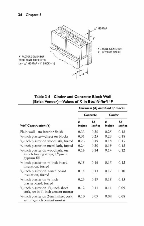
P1: GDZ/FFX P2: GDZ/FFX QC: GDZ/FFX T1: GDZ
GB076-03 GB076-Miller-Sample July 15, 2004 8:54 Char Count= 0
36 Chapter 3
1/2” MORTAR
4”
X = WALL & EXTERIORY = INTERIOR FINISH
K FACTORS GIVEN FOR TOTAL WALL THICKNESS(X + 1/2” MORTAR + 4” BRICK + Y )
XY
Table 3-6 Cinder and Concrete Block Wall(Brick Veneer)—Values of K in Btu/ ft2/hr/1◦F
Thickness (X) and Kind of Blocks
Concrete Cinder
8 12 8 12Wall Construction (Y) inches inches inches inches
Plain wall—no interior finish 0.33 0.26 0.25 0.181/2-inch plaster—direct on blocks 0.31 0.25 0.23 0.181/2-inch plaster on wood lath, furred 0.23 0.19 0.18 0.153/4-inch plaster on metal lath, furred 0.24 0.20 0.19 0.151/2-inch plaster on wood lath, on
2-inch furring strips, 15/8-inchgypsum fill
0.16 0.14 0.14 0.12
1/2-inch plaster on 1/2-inch boardinsulation, furred
0.18 0.16 0.15 0.13
1/2-inch plaster on 1-inch boardinsulation, furred
0.14 0.13 0.12 0.10
1/2-inch plaster on 3/8-inchplasterboard, furred
0.23 0.19 0.18 0.15
1/2-inch plaster on 11/2-inch sheetcork, set in 1/2-inch cement mortar
0.12 0.11 0.11 0.09
1/2-inch plaster on 2-inch sheet cork,set in 1/2-inch cement mortar
0.10 0.09 0.09 0.08

P1: GDZ/FFX P2: GDZ/FFX QC: GDZ/FFX T1: GDZ
GB076-03 GB076-Miller-Sample July 15, 2004 8:54 Char Count= 0
Heat Leakage 37
YX
4”
1/2” CEMENT MORTAR
K VALUES GIVEN FOR TOTAL WALL THICKNESS:X + 1/2” MORTAR + 4” BRICK + Y
X = WALL & EXTERIORY = INTERIOR FINISH
OUTSIDE
Table 3-7 Brick Veneer on Hollow Tile Wall(Brick Veneer)—Values of K in Btu/ ft2/hr/1◦F
Tile Thickness (X)
4 6 8 10 12Wall Construction (Y) inches inches inches inches inches
Plain wall—no interior finish 0.29 0.27 0.25 0.22 0.181/2-inch plaster on hollow tile 0.28 0.25 0.24 0.21 0.171/2-inch plaster on wood lath,
furred0.20 0.19 0.18 0.17 0.15
3/4-inch plaster on metal lath,furred
0.21 0.20 0.19 0.18 0.16
1/2-inch plaster on 3/8-inchplasterboard, furred
0.20 0.19 0.18 0.17 0.15
1/2-inch plaster on wood lath,on 2-inch furring strips,with 15/8-inch cellulargypsum fill
0.14 0.13 0.12 0.11 0.10
1/2-inch plaster on 1/2-inchboard insulation, furred
0.16 0.15 0.14 0.13 0.12
1/2-inch plaster on 1-inchboard insulation, furred
0.14 0.13 0.12 0.11 0.10
1/2-inch plaster on 11/2-inchboard insulation, furred
0.13 0.12 0.11 0.10 0.09
1/2-inch plaster on 2-inchboard insulation, furred
0.12 0.11 0.10 0.09 0.08
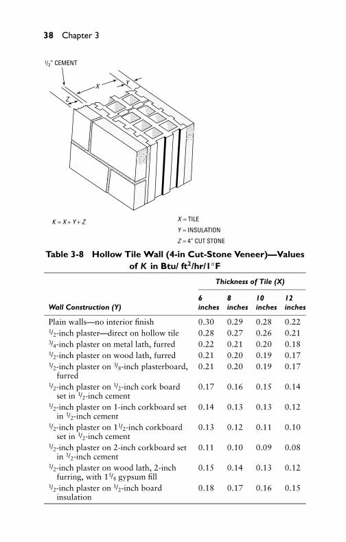
P1: GDZ/FFX P2: GDZ/FFX QC: GDZ/FFX T1: GDZ
GB076-03 GB076-Miller-Sample July 15, 2004 8:54 Char Count= 0
38 Chapter 3
1/2” CEMENT
Z
X Y
K = X + Y + Z X = TILE
Y = INSULATION
Z = 4” CUT STONE
Table 3-8 Hollow Tile Wall (4-in Cut-Stone Veneer)—Valuesof K in Btu/ ft2/hr/1◦F
Thickness of Tile (X)
6 8 10 12Wall Construction (Y) inches inches inches inches
Plain walls—no interior finish 0.30 0.29 0.28 0.221/2-inch plaster—direct on hollow tile 0.28 0.27 0.26 0.213/4-inch plaster on metal lath, furred 0.22 0.21 0.20 0.181/2-inch plaster on wood lath, furred 0.21 0.20 0.19 0.171/2-inch plaster on 3/8-inch plasterboard,
furred0.21 0.20 0.19 0.17
1/2-inch plaster on 1/2-inch cork boardset in 1/2-inch cement
0.17 0.16 0.15 0.14
1/2-inch plaster on 1-inch corkboard setin 1/2-inch cement
0.14 0.13 0.13 0.12
1/2-inch plaster on 11/2-inch corkboardset in 1/2-inch cement
0.13 0.12 0.11 0.10
1/2-inch plaster on 2-inch corkboard setin 1/2-inch cement
0.11 0.10 0.09 0.08
1/2-inch plaster on wood lath, 2-inchfurring, with 15/8 gypsum fill
0.15 0.14 0.13 0.12
1/2-inch plaster on 1/2-inch boardinsulation
0.18 0.17 0.16 0.15

P1: GDZ/FFX P2: GDZ/FFX QC: GDZ/FFX T1: GDZ
GB076-03 GB076-Miller-Sample July 15, 2004 8:54 Char Count= 0
Heat Leakage 39
YX
K VALUES GIVEN FOR TOTAL WALL THICKNESSX + Y + STUCCO FINISH
X = TILE THICKNESSY = INTERIOR FINISH
EXTERIOR STUCCO
Table 3-9 Hollow Tile Wall (Stucco Exterior)—Values of K inBtu/ ft2/hr/1◦F
Tile Thickness (X)
6 8 10 12 16Wall Construction (Y) inches inches inches inches inches
Plain wall with stucco—nointerior finish
0.32 0.30 0.28 0.22 0.18
1/2-inch plaster—direct onhollow tile
0.31 0.29 0.27 0.21 0.17
1/2-inch plaster on wood lath,furred
0.22 0.20 0.18 0.16 0.12
3/4-inch plaster on metal lath,furred
0.23 0.21 0.19 0.17 0.13
1/2-inch plaster on 3/8-inchplasterboard, furred
0.21 0.20 0.18 0.16 0.12
1/2-inch plaster on wood lath, on2-inch furring strips, with15/8-inch cellular gypsum fill
0.16 0.15 0.14 0.13 0.12
1/2-inch plaster on 1/2-inch boardinsulation, furred
0.15 0.14 0.13 0.12 0.11
1/2-inch plaster on 1-inch boardinsulation, furred
0.13 0.12 0.11 0.10 0.09
1/2-inch plaster on 11/2-inchboard insulation, furred
0.12 0.11 0.10 0.09 0.08
1/2-inch plaster on 2-inch boardinsulation, furred
0.11 0.10 0.09 0.08 0.07

P1: GDZ/FFX P2: GDZ/FFX QC: GDZ/FFX T1: GDZ
GB076-03 GB076-Miller-Sample July 15, 2004 8:54 Char Count= 0
40 Chapter 3
X
Y
K = X + YX = WALLY = INTERIOR CONSTRUCTION
Table 3-10 Limestone or Sandstone Wall—Values of K inBtu/ ft2/hr/1◦F
Thickness (X)
8 10 12 16Wall Construction (Y) inches inches inches inches
Plain wall—no interior finish 0.56 0.50 0.48 0.391/2-inch plaster—direct on stone 0.50 0.45 0.42 0.363/4-inch plaster on metal lath, furred 0.33 0.31 0.29 0.261/2-inch plaster on wood lath, furred 0.31 0.29 0.28 0.251/2-inch plaster on 3/4-inch plasterboard,
furred0.31 0.30 0.28 0.25
1/2-inch plaster on wood lath, 2-inchfurring strips, with 15/8-inch cellulargypsum fill
0.20 0.19 0.18 0.17
1/2-inch plaster on 1/2-inch boardinsulation, furred
0.23 0.22 0.21 0.19
1/2-inch plaster on 1-inch boardinsulation, furred
0.17 0.16 0.15 0.14
1/2-inch plaster on 11/2-inch corkboard,set in 1/2-inch cement
0.14 0.14 0.13 0.12
1/2-inch plaster on 2-inch corkboard, setin 1/2-inch cement
0.11 0.11 0.10 0.10
1/2-inch plaster on wood lath, on 2-inchfurring strips, with 2-inch cellulargypsum fill
0.19 0.18 0.17 0.16

P1: GDZ/FFX P2: GDZ/FFX QC: GDZ/FFX T1: GDZ
GB076-03 GB076-Miller-Sample July 15, 2004 8:54 Char Count= 0
Heat Leakage 41
1/2” M0RTAR
INTERIOR FINISH
K = X + YX = WALLY = INTERIORZ = 4” STONE 81/2” MORTAR
Y
XZ4”
Table 3-11 Brick Wall (4-in Cut Stone)—Values of K inBtu/ft2/hr/1◦F
Thickness (X)
Wall 8 9 12 13 16 18 24Construction (Y) inches inches inches inches inches inches inches
Plain wall—nointerior finish
0.33 0.29 0.26 0.25 0.22 0.20 0.16
1/2-inch plaster—direct on brick
0.31 0.28 0.25 0.24 0.21 0.19 0.15
3/4-inch plaster onmetal lath, furred
0.23 0.22 0.20 0.19 0.18 0.17 0.15
1/2-inch plaster onwood lath, furred
0.22 0.21 0.19 0.18 0.17 0.15 0.12
1/2-inch plaster on3/8-inch plaster-board, furred
0.23 0.22 0.20 0.19 0.18 0.17 0.14
1/2-inch plaster, lath,2-inch furringstrips, with 15/8-inch gypsum fill
0.16 0.15 0.14 0.13 0.12 0.11 0.10
1/2-inch plaster on1/2-inch sheet cork
0.18 0.16 0.15 0.14 0.13 0.12 0.11
1/2-inch plaster on1-inch sheet cork
0.14 0.13 0.12 0.11 0.10 0.10 0.09
1/2-inch plaster on11/2-inch sheetcork
0.12 0.12 0.11 0.11 0.10 0.10 0.09
1/2-inch plaster on2-inch sheet cork
0.11 0.10 0.10 0.09 0.09 0.08 0.08

P1: GDZ/FFX P2: GDZ/FFX QC: GDZ/FFX T1: GDZ
GB076-03 GB076-Miller-Sample July 15, 2004 8:54 Char Count= 0
42 Chapter 3
K = X + YX = WALLY = INTERIOR CONSTRUCTION X
Y
Table 3-12 Solid Brick Wall (No Exterior Finish)—Values of K inBtu/ft2/hr/1◦F
Thickness (X)
Wall 8 9 12 13 16 18 24Construction (Y) inches inches inches inches inches inches inches
Plain wall—nointerior finish
0.39 0.37 0.30 0.29 0.24 0.23 0.18
1/2-inch plaster—direct on brick
0.36 0.35 0.28 0.27 0.23 0.20 0.16
3/4-inch plaster onmetal lath, furred
0.26 0.25 0.23 0.21 0.19 0.18 0.15
1/2-inch plaster onwood lath, furred
0.25 0.24 0.21 0.19 0.18 0.17 0.14
1/2-inch plaster on3/8-inch plaster-board, furred
0.24 0.23 0.20 0.18 0.17 0.16 0.14
1/2-inch plaster on1/2-inch boardinsulation, furred
0.20 0.19 0.18 0.17 0.16 0.15 0.13
1/2-inch plaster on 1/2-inch sheet cork, setin 1/2-inch cement
0.18 0.17 0.16 0.15 0.14 0.13 0.12
1/2-inch plaster on 1-inch sheet cork, setin 1/2-inch cement
0.15 0.14 0.13 0.12 0.11 0.10 0.09
1/2-inch plaster on11/2-inch sheet cork,set in 1/2-inch cement
0.14 0.13 0.12 0.11 0.10 0.09 0.08
1/2-inch plaster on 2-inch sheet cork, setin 1/2-inch cement
0.13 0.12 0.11 0.10 0.09 0.08 0.07
1/2-inch plaster on11/2-inch splitfurring, tiled
0.28 0.26 0.23 0.22 0.20 0.19 0.17
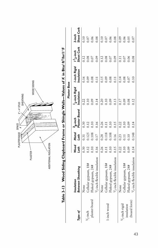
P1: GDZ/FFX P2: GDZ/FFX QC: GDZ/FFX T1: GDZ
GB076-03 GB076-Miller-Sample July 15, 2004 8:54 Char Count= 0
Tabl
e3-
13W
oo
dS
idin
gC
lapb
oar
dFr
ame
or
Shi
ngle
Wal
ls—
Val
ues
of
Kin
Btu
/ft2
/hr/
1◦ F
PLAS
TER
BASE
SPAC
E
PLAS
TER
WOO
D SI
DIN
G
SHEA
THIN
G2"
× 4
" STU
D
ADDI
TION
AL IN
SULA
TION
Pla
ster
Bas
e
Insu
lati
onW
ood
Met
al3 / 8
-inc
h1 / 2
-inc
hR
igid
1-in
chR
igid
11/ 2
-inc
h2-
inch
Typ
eof
Bet
wee
nSh
eath
ing
Lath
Lath
Pla
ster
Boa
rdIn
sula
tion
Insu
lati
onSh
eet
Cor
kSh
eet
Cor
k
1 /2-
inch
plas
ter-
boar
d
Non
e0.
300.
310.
300.
220.
160.
120.
10C
ellu
lar
gyps
um,1
8#0.
120.
125
0.12
0.10
0.09
0.08
0.07
Flak
edgy
psum
,24#
0.10
0.10
80.
100.
090.
080.
070.
061 /
2-in
chfle
xibl
ein
sula
tion
0.16
0.17
0.16
0.14
0.11
0.09
0.08
1-in
chw
ood
Non
e0.
260.
280.
260.
200.
150.
120.
10C
ellu
lar
gyps
um,1
8#0.
110.
118
0.11
0.10
0.09
0.08
0.07
Flak
edgy
psum
,24#
0.10
0.10
80.
100.
090.
080.
070.
061 /
2-in
chfle
xibl
ein
sula
tion
0.15
0.16
0.15
0.13
0.11
0.09
0.08
1 /2-
inch
rigi
din
sula
tion
(boa
rdfo
rm)
Non
e0.
220.
230.
220.
170.
140.
110.
09C
ellu
lar
gyps
um,1
8#0.
100.
110.
100.
090.
080.
070.
06Fl
aked
gyps
um,2
4#0.
090.
100.
090.
080.
070.
060.
051 /
2-in
chfle
xibl
ein
sula
tion
0.14
0.14
80.
140.
120.
100.
080.
07
43
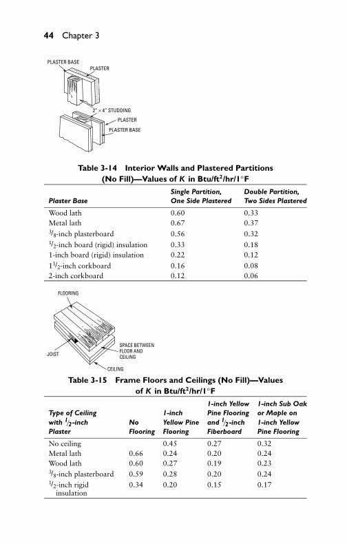
P1: GDZ/FFX P2: GDZ/FFX QC: GDZ/FFX T1: GDZ
GB076-03 GB076-Miller-Sample July 15, 2004 8:54 Char Count= 0
44 Chapter 3
PLASTER BASE
PLASTER BASE
PLASTER
PLASTER
2” × 4” STUDDING
Table 3-14 Interior Walls and Plastered Partitions(No Fill)—Values of K in Btu/ft2/hr/1◦F
Single Partition, Double Partition,Plaster Base One Side Plastered Two Sides Plastered
Wood lath 0.60 0.33Metal lath 0.67 0.373/8-inch plasterboard 0.56 0.321/2-inch board (rigid) insulation 0.33 0.181-inch board (rigid) insulation 0.22 0.12
11/2-inch corkboard 0.16 0.082-inch corkboard 0.12 0.06
FLOORING
SPACE BETWEENFLOOR AND CEILING
CEILING
JOIST
Table 3-15 Frame Floors and Ceilings (No Fill)—Valuesof K in Btu/ft2/hr/1◦F
1-inch Yellow 1-inch Sub OakType of Ceiling 1-inch Pine Flooring or Maple onwith 1/2-inch No Yellow Pine and 1/2-inch 1-inch YellowPlaster Flooring Flooring Fiberboard Pine Flooring
No ceiling 0.45 0.27 0.32Metal lath 0.66 0.24 0.20 0.24Wood lath 0.60 0.27 0.19 0.233/8-inch plasterboard 0.59 0.28 0.20 0.241/2-inch rigid
insulation0.34 0.20 0.15 0.17

P1: GDZ/FFX P2: GDZ/FFX QC: GDZ/FFX T1: GDZ
GB076-03 GB076-Miller-Sample July 15, 2004 8:54 Char Count= 0
Heat Leakage 45
4”
4”
4”
BARE–NO PLASTER
PLASTERED ONE SIDE
PLASTER
PLASTERED BOTH SIDES
1/2”
1/2”
Table 3-16 Masonry Partitions—Valuesof K in Btu/ft2/hr/1◦F
Bare, One Side Two SidesWall No Plaster Plastered Plastered
4-inch brick 0.48 0.46 0.414-inch hollow gypsum tile 0.29 0.27 0.264-inch hollow clay tile 0.44 0.41 0.39

P1: GDZ/FFX P2: GDZ/FFX QC: GDZ/FFX T1: GDZ
GB076-03 GB076-Miller-Sample July 15, 2004 8:54 Char Count= 0
Tabl
e3-
17C
onc
rete
Flo
ors
(on
Gro
und)
—V
alue
so
fK
inB
tu/ft
2/h
r/1◦ F
WOO
D SL
EEPE
RS
IMBE
DDED
IN
CON
CRET
E WAT
ERPR
OOF
MEM
BRAN
ES
OAK
OR M
APLE
FLO
OR
WOO
D FL
OOR
OR S
UB
FLOO
R
THIC
KNES
S OF
CON
CRET
E ( X
)
INSU
LATI
ON ( Y
)
3” O
F TA
MPE
D CI
NDE
R OR
CIN
DER
CON
CRET
E (Z
)
Tile
or1-
inch
Oak
orM
aple
onTy
pe
ofT
hick
ness
Con
cret
eN
oTe
rraz
zoYe
llow
Pin
eon
Yello
wP
ine
Sub
Insu
lati
onof
YT
hick
ness
XFl
oori
ngFl
oor
Woo
dSl
eep
ers
Floo
ron
Slee
per
s
Non
e,an
dno
04
1.02
00.
930
0.51
00.
370
cind
erba
se(Z
)0
50.
940
0.83
00.
480
0.36
00
60.
860
0.79
00.
460
0.34
00
80.
760
0.70
00.
430
0.32
0N
one,
wit
h0
40.
580
0.55
00.
510
0.31
03-
inch
cind
er0
50.
550
0.52
00.
470
0.30
0ba
se(Z
)0
60.
520
0.49
00.
440
0.29
00
80.
500
0.47
00.
400
0.28
01-
inch
rigi
d1-
inch
40.
220
0.21
00.
180
0.16
5in
sula
tion
(Y)
1-in
ch5
0.21
00.
200
0.17
50.
160
wit
h3-
inch
1-in
ch6
0.20
00.
190
0.17
00.
155
cind
erba
se(Z
)1-
inch
80.
190
0.18
00.
160
0.15
02-
inch
cork
boar
d2-
inch
40.
125
0.12
00.
115
0.10
5in
sula
tion
(Y)
2-in
ch5
0.12
00.
115
0.11
00.
100
wit
h3-
inch
2-in
ch6
0.11
50.
110
0.10
50.
095
cind
erba
se(Z
)2-
inch
80.
110
0.10
50.
100
0.09
0
46

P1: GDZ/FFX P2: GDZ/FFX QC: GDZ/FFX T1: GDZ
GB076-03 GB076-Miller-Sample July 15, 2004 8:54 Char Count= 0
Heat Leakage 47
IMBEDDED SLEEPERS
AIR SPACE
PLASTER
PLASTER BASE
OAK OR MAPLE FLOOR WOOD FLOORING OR
SUBFLOOR
CONCRETE
Table 3-18 Concrete Floors and Ceilings—Values of K in Btu/ft2/hr/1◦F
Floor Type
Oak or MapleTile or 1-inch Yellow on Yellow Pine,
Type of Ceiling No Terrazzo Pine on Wood Sub Floor onand Base Thickness Flooring Floor Sleepers Sleeper
No ceiling 4 0.60 0.57 0.38 0.296 0.54 0.52 0.35 0.288 0.48 0.46 0.33 0.26
10 0.46 0.44 0.31 0.25
1/2-inch 4 0.56 0.53 0.38 0.30plaster—direct on 6 0.51 0.49 0.35 0.29concrete
8 0.47 0.44 0.33 0.2710 0.42 0.41 0.31 0.26
Suspended 4 0.33 0.32 0.24 0.20or furredceiling on 6 0.31 0.30 0.23 0.193/8-inchplasterboard, 8 0.29 0.28 0.22 0.181/2-inchplaster 10 0.28 0.27 0.21 0.17
(continued )

P1: GDZ/FFX P2: GDZ/FFX QC: GDZ/FFX T1: GDZ
GB076-03 GB076-Miller-Sample July 15, 2004 8:54 Char Count= 0
48 Chapter 3
Table 3-18 (continued)
Floor Type
Oak or MapleTile or 1-inch Yellow on Yellow Pine,
Type of Ceiling No Terrazzo Pine on Wood Sub Floor onand Base Thickness Flooring Floor Sleepers Sleeper
Suspended 4 0.36 0.34 0.26 0.21or furred 6 0.34 0.32 0.24 0.20metal lath, 8 0.32 0.30 0.23 0.193/4-inch 10 0.31 0.29 0.22 0.18plaster
Suspended or 4 0.22 0.21 0.20 0.18furred on 1/2-inch 6 0.21 0.20 0.19 0.17rigid insulation, 8 0.20 0.19 0.18 0.161/2 -inch plaster 10 0.19 0.18 0.17 0.15
11/2 -inch cork- 4 0.16 0.15 0.14 0.13board in 1/2-inch 6 0.15 0.14 0.13 0.12mortar, 1/2-inch 8 0.14 0.13 0.12 0.11mortar, 1/2 inch 10 0.13 0.12 0.11 0.10plaster

P1: GDZ/FFX P2: GDZ/FFX QC: GDZ/FFX T1: GDZ
GB076-03 GB076-Miller-Sample July 15, 2004 8:54 Char Count= 0
Heat Leakage 49
JOIST
CEILING
FLOORING
FILL
Table 3-19 Frame Floors and Ceilings (with Fill)—Valuesof K in Btu/ ft2/hr/1◦F
1-inch SubType of 1-inch 1-inch Yellow Oak, MapleCeiling Insulation or Yellow Pine Flooring on 1-inchwith 1/2-inch Fill Between No Pine and 1/2-inch Yellow PinePlaster Joists Flooring Flooring Fiberboard Flooring
Wood lath 1/2-inch flexibleinsulation
0.220 0.150 0.120 0.140
Wood lath 1/2-inch rigidinsulation
0.240 0.160 0.130 0.150
Wood lath Flaked 2-inchgypsum
0.150 0.120 0.105 0.120
Wood lath Rock wool,2-inch
0.120 0.095 0.080 0.090
Corkboard1/2-inch
None 0.155 0.115 0.100 0.105
Corkboard1/2-inch
None 0.120 0.100 0.085 0.095
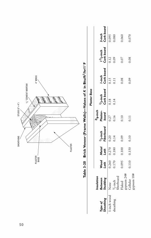
P1: GDZ/FFX P2: GDZ/FFX QC: GDZ/FFX T1: GDZ
GB076-03 GB076-Miller-Sample July 15, 2004 8:54 Char Count= 0
Tabl
e3-
20B
rick
Ven
eer
(Fra
me
Wal
ls)—
Val
ues
of
Kin
Btu
/ft2/h
r/1◦ F
SHEA
THIN
G
PLAS
TER
BASE
PLAS
TER
STUD
S (2
”× 4
”) 1 / 2”
CEM
ENT
MOR
TAR 4”
BRI
CK
Pla
ster
Bas
e
Insu
lati
on3 /
8-in
chTy
pe
ofB
etw
een
Woo
dM
etal
1 /2-
inch
Pla
ster
-1 /
2-in
ch1-
inch
11 /2-
inch
2-in
chSh
eath
ing
Stud
ding
Lath
Lath
Fibe
rboa
rdbo
ard
Cor
kbo
ard
Cor
kbo
ard
Cor
kbo
ard
Cor
kbo
ard
1-in
chw
ood
Non
e0.
260
0.27
00.
200.
270.
180.
150.
120.
095
shea
thin
g1 /
2-in
ch0.
170
0.18
00.
140.
160.
140.
110.
090.
080
fiber
boar
dFl
aked
0.09
50.
100
0.09
0.10
0.08
0.07
0.06
0gy
psum
24#
Cel
lula
r0.
110
0.15
00.
100.
110.
090.
080.
070
gyps
um18
#
50

P1: GDZ/FFX P2: GDZ/FFX QC: GDZ/FFX T1: GDZ
GB076-03 GB076-Miller-Sample July 15, 2004 8:54 Char Count= 0
1 /2-
inch
Non
e0.
320
0.34
00.
240.
300.
160.
130.
110
plas
ter-
1 /2-
inch
0.18
00.
190
0.14
0.17
0.11
0.09
0.08
0bo
ard
fiber
boar
dsh
eath
ing
Flak
ed0.
100
0.11
00.
090.
100.
080.
070.
060
gyps
um24
#C
ellu
lar
0.12
00.
120
0.10
0.12
0.09
0.08
0.07
0gy
psum
18#
1 /2-
inch
Non
e0.
250
0.26
00.
190.
260.
150.
120.
100
fiber
boar
d1 /
2-in
ch0.
160
0.17
00.
130.
150.
100.
090.
080
(rig
id)
fiber
boar
din
sula
tion
Flak
ed0.
090
0.09
00.
080.
090.
070.
070.
060
shea
thin
ggy
psum
24#
Cel
lula
r0.
100
0.10
50.
090.
100.
080.
070.
060
gyps
um18
#
51
P1: GDZ/FFX P2: GDZ/FFX QC: GDZ/FFX T1: GDZ
GB076-03 GB076-Miller-Sample July 15, 2004 8:54 Char Count= 0
52 Chapter 3
SummaryBuilding materials affect the design of air-conditioning and heatingsystems. Heat loss through walls, floors, and ceilings is a primeconsideration when calculating and installing an air conditioner.
Heat leakage is always given in Btu per hour per degree Fahren-heit temperature difference per square foot of exposed surface(Btu/ft2/hr/◦F). Prior to designing an air-conditioning system, an es-timate must be made of the maximum heat loss of each room orspace to be cooled. One ton of refrigeration equals 12,000 Btu/hr.It is an easy matter to calculate the required size of equipment sinceall that is necessary is to divide the combined sum of leakage andcooling loads (in Btu/hr) by 12,000 to obtain the condensing unitcapacity.
Review Questions1. How do the thermal properties of building materials affect the
design of air-conditioning systems?2. What is meant by air leakage in buildings, and what is the
method of air-leakage reduction?3. State the various factors affecting the size of an air-
conditioning system in residential projects.4. Define the method of heat-leakage calculation.5. Upon what factors is the heat-leakage formula based?6. Calculate the heat leakage in Btu/hr for a plain 10-inch con-
crete wall (no exterior finish) having an area of 325 ft2 for atemperature difference of 40◦F.
7. Why is the heat leakage through walls, ceilings, and floorsan important consideration when installing air-conditioningplants?
8. What is meant by heat loss?9. What does infiltration mean when speaking of heat loss?
10. What are K values?

P1: GDZ/FFX P2: GDZ/FFX QC: GDZ/FFX T1: GDZ
GB076-04 GB076-Miller-Sample July 15, 2004 16:53 Char Count= 0
Chapter 4Ventilation RequirementsBy definition, ventilation is the process of supplying or removing airto or from any building or space. Such air may or may not havebeen conditioned. Methods of supplying or removing the air areaccomplished by natural ventilation and mechanical methods.
Natural ventilation is obtained by opening or closing windowsashes and by using vents or ventilators above the roof, chimneydrafts, and so on. Mechanical ventilation is produced by the useof fans or other means to force the air through the space to beventilated.
Air LeakageAir leakage caused by cold air outside and warm air inside takesplace when the building contains cracks or openings at differentlevels. This results in the cold and heavy air entering at low levelsand pushing the warm and light air out at high levels; the samedraft takes place in a chimney. When storm sashes are appliedto well-fitted windows, very little redirection in infiltration is se-cured, but the application of the sash does give an air space thatreduces heat transmission and helps prevent window frosting. Byapplying storm sashes to poorly fitted windows, a reduction in leak-age of up to 50 percent may be obtained. The effect, insofar as airleakage is concerned, will be roughly equivalent to that obtained bythe installation of weather stripping.
Natural VentilationThe two natural forces available for moving air through and out ofbuildings are wind forces and temperature difference between theinside and the outside. Air movement may be caused by either ofthese forces acting alone, or by a combination of the two, dependingon atmospheric conditions, building design, and location.
Wind ForcesIn considering the use of natural forces for producing ventilation,the conditions that must be considered are as follows:
� Average wind velocity� Prevailing wind direction� Seasonal and daily variations in wind velocity and direction� Local wind interference by buildings and other obstructions
53
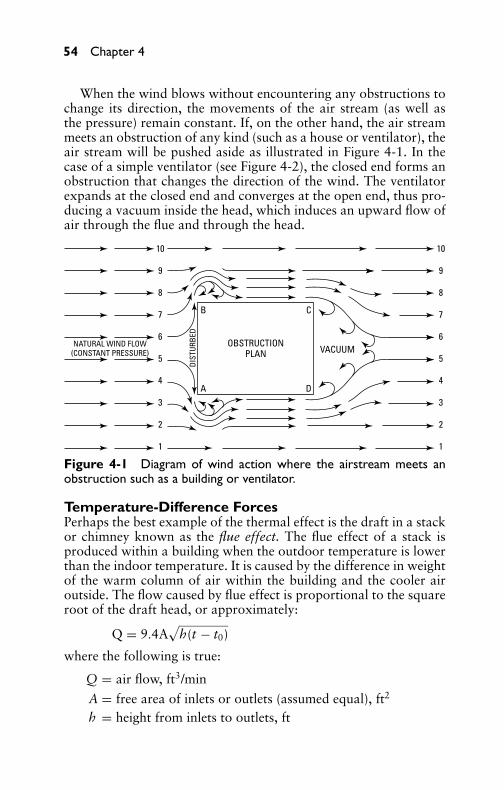
P1: GDZ/FFX P2: GDZ/FFX QC: GDZ/FFX T1: GDZ
GB076-04 GB076-Miller-Sample July 15, 2004 16:53 Char Count= 0
54 Chapter 4
When the wind blows without encountering any obstructions tochange its direction, the movements of the air stream (as well asthe pressure) remain constant. If, on the other hand, the air streammeets an obstruction of any kind (such as a house or ventilator), theair stream will be pushed aside as illustrated in Figure 4-1. In thecase of a simple ventilator (see Figure 4-2), the closed end forms anobstruction that changes the direction of the wind. The ventilatorexpands at the closed end and converges at the open end, thus pro-ducing a vacuum inside the head, which induces an upward flow ofair through the flue and through the head.
OBSTRUCTIONPLAN
B
A
C
D
VACUUMNATURAL WIND FLOW
(CONSTANT PRESSURE)
DIST
URBE
D
10
9
8
7
6
5
4
3
2
1
10
9
8
7
6
5
4
3
2
1
Figure 4-1 Diagram of wind action where the airstream meets anobstruction such as a building or ventilator.
Temperature-Difference ForcesPerhaps the best example of the thermal effect is the draft in a stackor chimney known as the flue effect. The flue effect of a stack isproduced within a building when the outdoor temperature is lowerthan the indoor temperature. It is caused by the difference in weightof the warm column of air within the building and the cooler airoutside. The flow caused by flue effect is proportional to the squareroot of the draft head, or approximately:
Q = 9.4A√
h(t − t0)
where the following is true:
Q = air flow, ft3/min
A = free area of inlets or outlets (assumed equal), ft2
h = height from inlets to outlets, ft

P1: GDZ/FFX P2: GDZ/FFX QC: GDZ/FFX T1: GDZ
GB076-04 GB076-Miller-Sample July 15, 2004 16:53 Char Count= 0
Ventilation Requirements 55
B
A
C
D
VACUUM
ELEVATION10
9
8
7
6
5
4
3
2
1
10
9
8
7
6
5
4
3
2
1CONNECTING FLUE HIGH PRESSURE
LOW PRESSURE
OBSTRUCTION (HEAD OF VENTILATOR)
INDU
CTIV
EACTION
Figure 4-2 Airflow in a roof ventilator.
t = average temperature of indoor air, ◦Ft0 = temperature of outdoor air, ◦F
9.4 = constant of proportionality (including a value of65 percent for effectiveness of openings)
The constant of proportionality should be reduced by 50 percent(constant = 7.2) if conditions are not favorable.
Combined Wind and Temperature ForcesNote that when wind and temperature forces are acting together,even without interference, the resulting air flow is not equal to thesum of the two estimated quantities. However, the flow through anyopening is proportional to the square root of the sum of the headsacting on that opening. When the two heads are equal in value,and the ventilating openings are operated so as to coordinate them,the total airflow through the building is about 10 percent greaterthan that produced by either head acting independently under idealconditions. This percentage decreases rapidly as one head increasesover the other. The larger head will predominate.
Roof VentilatorsThe function of a roof ventilator is to provide a storm and weath-erproof air outlet. For maximum flow by induction, the ventilatorshould be located on that part of the roof where it will receive the fullwind without interference. Roof ventilators are made in a variety ofshapes and styles (see Figure 4-3). Depending on their construction
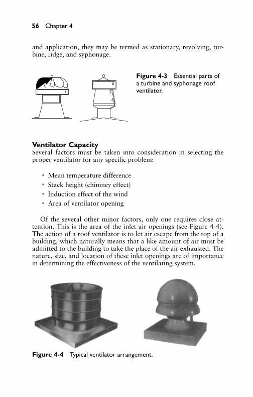
P1: GDZ/FFX P2: GDZ/FFX QC: GDZ/FFX T1: GDZ
GB076-04 GB076-Miller-Sample July 15, 2004 16:53 Char Count= 0
56 Chapter 4
and application, they may be termed as stationary, revolving, tur-bine, ridge, and syphonage.
Figure 4-3 Essential parts ofa turbine and syphonage roofventilator.
Ventilator CapacitySeveral factors must be taken into consideration in selecting theproper ventilator for any specific problem:
� Mean temperature difference� Stack height (chimney effect)� Induction effect of the wind� Area of ventilator opening
Of the several other minor factors, only one requires close at-tention. This is the area of the inlet air openings (see Figure 4-4).The action of a roof ventilator is to let air escape from the top of abuilding, which naturally means that a like amount of air must beadmitted to the building to take the place of the air exhausted. Thenature, size, and location of these inlet openings are of importancein determining the effectiveness of the ventilating system.
Figure 4-4 Typical ventilator arrangement.

P1: GDZ/FFX P2: GDZ/FFX QC: GDZ/FFX T1: GDZ
GB076-04 GB076-Miller-Sample July 15, 2004 16:53 Char Count= 0
Ventilation Requirements 57
Fresh-Air RequirementsTable 4-1 is a guide to the amount of air required for efficient ven-tilation. This information should be used in connection with theventilator-capacity tables provided by fan manufacturers to assist inthe proper selection of the number and size of the units required.
Table 4-1 Fresh-Air Requirements
Minimum Air Cubic Feet ofType of Building or Changes Air per MinuteRoom per Hour per Occupant
Attic spaces (for cooling) 12–15Boiler room 15–20Churches, auditoriums 8 20–30College classrooms 25–30Dining rooms (hotel) 5Engine rooms 4–6Factory buildings
Ordinary manufacturing 2–4Extreme fumes or 10–15moisture
Foundries 15–20Galvanizing plants 20–30∗
GaragesRepair 20–30Storage 4–6
Homes (night cooling) 9–17Hospitals
General 40–50Children’s 35–40Contagious diseases 89–90
KitchensHotel 10–20Restaurant 10–20
Libraries (public) 4Laundries 10–15Mills
Paper 15–20∗
Textile-general 4(continued )

P1: GDZ/FFX P2: GDZ/FFX QC: GDZ/FFX T1: GDZ
GB076-04 GB076-Miller-Sample July 15, 2004 16:53 Char Count= 0
58 Chapter 4
Table 4-1 (continued)
Minimum Air Cubic Feet ofType of Building Changes Air per Minuteor Room per Hour per Occupant
buildingsTextile-dye houses 15–20∗
OfficesPublic 3Private 4
Pickling plants 10–15†
Pump rooms 5Restaurants 8–12Schools
Grade 15–25High 30–35
ShopsMachine 5Paint 15–20∗
Railroad 5Woodworking 5
Substations (electric) 5–10Theaters 10–15Turbine rooms (electric) 5–10Warehouses 2Waiting rooms (public) 4
∗Hoods should be installed over vats or machines.†Unit heaters should be directed on vats to keep fumes superheated.
Mechanical VentilationMechanical ventilation differs from natural ventilation mainly inthat the air circulation is performed by mechanical means (suchas fans or blowers). In natural ventilation, the air is caused tomove by natural forces. In mechanical ventilation, the required airchanges are effected partly by diffusion, but chiefly by positive cur-rents put in motion by electrically operated fans or blowers, asshown in Figure 4-5. Fresh air is usually circulated through registersconnected with the outside and warmed as it passes over and throughthe intervening radiators.
Volume of Air RequiredThe volume of air required is determined by the size of the space tobe ventilated and the number of times per hour that the air in the
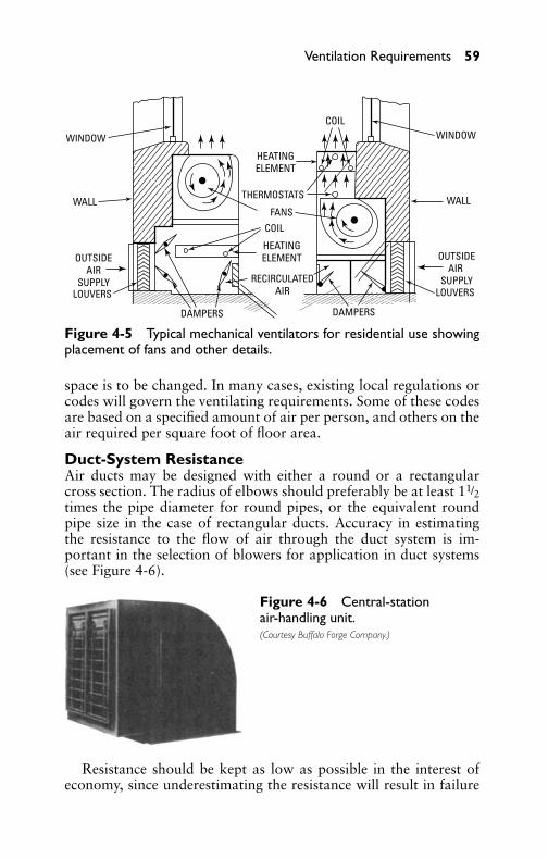
P1: GDZ/FFX P2: GDZ/FFX QC: GDZ/FFX T1: GDZ
GB076-04 GB076-Miller-Sample July 15, 2004 16:53 Char Count= 0
Ventilation Requirements 59
WINDOW
WALL
OUTSIDEAIR
SUPPLYLOUVERS
DAMPERS DAMPERS
WINDOW
WALL
OUTSIDEAIR
SUPPLYLOUVERS
HEATINGELEMENT
HEATINGELEMENT
RECIRCULATEDAIR
THERMOSTATS
FANS
COIL
COIL
Figure 4-5 Typical mechanical ventilators for residential use showingplacement of fans and other details.
space is to be changed. In many cases, existing local regulations orcodes will govern the ventilating requirements. Some of these codesare based on a specified amount of air per person, and others on theair required per square foot of floor area.
Duct-System ResistanceAir ducts may be designed with either a round or a rectangularcross section. The radius of elbows should preferably be at least 11/2times the pipe diameter for round pipes, or the equivalent roundpipe size in the case of rectangular ducts. Accuracy in estimatingthe resistance to the flow of air through the duct system is im-portant in the selection of blowers for application in duct systems(see Figure 4-6).
Figure 4-6 Central-stationair-handling unit.(Courtesy Buffalo Forge Company.)
Resistance should be kept as low as possible in the interest ofeconomy, since underestimating the resistance will result in failure

P1: GDZ/FFX P2: GDZ/FFX QC: GDZ/FFX T1: GDZ
GB076-04 GB076-Miller-Sample July 15, 2004 16:53 Char Count= 0
60 Chapter 4
of the blower to deliver the required volume of air. You should care-fully study the building drawings with consideration paid to ductlocations and clearances. Keep all duct runs as short as possible,bearing in mind that the airflow should be conducted as directlyas possible from the source to the delivery points. Select the loca-tions of the duct outlets to ensure proper air distribution. The ductsshould be provided with cross-sectional areas that will permit airto flow at suitable velocities. Moderate velocities should be used inall ventilating work to avoid waste of power and to reduce noise.Lower velocities are more frequently used in schools, churches, the-aters, and so on, instead of factories and other places where noisecaused by airflow is not objectionable.
Air FiltrationThe function of air filters as installed in air-conditioning systemsis to remove the airborne dust that tends to settle in the air of theventilated space and may become a menace to human health if notproperly removed.
Effect of Dust on HealthThe effect of dust on health has been properly emphasized by com-petent medical authorities. The normal human breathes about 17times a minute. The air taken into the lungs may contain large quan-tities of dust, soot, germs, bacteria, and other deleterious matter.Most of this solid matter is removed in the nose and air passagesof the normal person. However, if these passages are dry and per-mit the passage of these materials, colds and respiratory diseasesresult. Air-conditioning apparatus remove these contaminants fromthe air and further provide the correct amount of moisture so that therespiratory tracts are not dehydrated, but are kept properly moist.Among the airborne diseases are mumps, measles, scarlet fever,pneumonia, colds, tuberculosis, hay fever, grippe, influenza, anddiphtheria.
Dust is more than just dry dirt. It is exceedingly complex, withvariable mixtures of materials, and, as a whole, is rather uninvit-ing, especially the type found in and around human habitation.Dust contains fine particles of sand, soot, earth, rust, fiber, animaland vegetable refuse, hair, chemicals, and compounds, all of whichare abrasive, irritating, or both. The U.S. Weather Bureau estimatesthat there are 115,000 particles of dust per cubic inch of ordinarycity air, and that each grain of this dust at breathing level containsfrom 85,000 to 125,000 germs. The proximity of factories using oilor coal-burning equipment and the presence of considerable street

P1: GDZ/FFX P2: GDZ/FFX QC: GDZ/FFX T1: GDZ
GB076-04 GB076-Miller-Sample July 15, 2004 16:53 Char Count= 0
Ventilation Requirements 61
traffic will aggravate this condition and increase the dust and germcontent.
The Mellon Institute of Industrial Research conducted a seriesof experiments to determine dust precipitation in three large cities.The measurements published were the average amounts measuredin more than ten stations in each of the cities and were for a pe-riod of one year. It was observed that precipitation was consider-ably greater in the industrial districts. It is certainly plain that fil-tered air is almost a necessity, especially in large buildings wherea number of individuals are gathered. Hotels, theaters, schools,stores, hospitals, factories, and museums require the removal of dustfrom the atmosphere admitted to their interiors, not only becausea purer product is made available for human health and consump-tion, but also so that the fittings, clothing, furniture, and equipmentwill not be damaged by the dust particles borne by the fresh airstream.
The air filter is one part of the air-conditioning system that shouldbe operated the year around. There are times when the air washer(the cooling and humidifying apparatus) is not needed, but the filteris one part of the system that should be kept in continuous operation,purifying the air.
Various Dust SourcesThe dust removed in the filters may be classified as poisonous, in-fective, obstructive, or irritating and may originate from an animal,vegetable, mineral, or metallic source. Industry produces many dele-terious fumes and dusts, for example, those emanating from grind-ing, polishing, dyeing, gilding, painting, spraying, cleaning, pulver-izing, baking, mixing of poisons, sawing, and sand blasting. Thisdust must be filtered out of the air because of its effect on healthand efficiency, to recover valuable materials, to save heat by reusingfiltered air, and to prevent damage to equipment and products in thecourse of manufacturing.
Air-Filter ClassificationAir-cleaning equipment may be classified according to the followingmethods used:
� Filtering� Washing� Combined filtering and washing

P1: GDZ/FFX P2: GDZ/FFX QC: GDZ/FFX T1: GDZ
GB076-04 GB076-Miller-Sample July 15, 2004 16:53 Char Count= 0
62 Chapter 4
There are several types of filters divided into two main classes:dry and wet. The wet filters may again be subdivided into what isknown as the manual and automatic self-cleaning types.
Dry FiltersDry filters are usually made in standard units of definite rated ca-pacity and resistance to the passage of air. At the time the instal-lation is designed, ample filter area must be included so that theair velocity passing through the filters is not excessive; otherwise,proper filtration will not be secured. The proper area is secured bymounting the proper number of filters on an iron frame. A dry filter(see Figure 4-7) may be provided with permanent filtering materialfrom which the dirt and dust must be removed pneumatically or byvibration. Or, it may be provided with an inexpensive filter mediumthat can be dispensed with when loaded with dirt and replaced witha new slab.
Figure 4-7 Typical air-filterpanel absorber containingactivated charcoal forheavy-duty control of odorsand vapors.(Courtesy Barneby Cheney Corporation.)
A dry-type filter is known as a dry plate. The cells are composedof a number of perforated aluminum plates, arranged in series andcoated with a fireproof filament. Air drawn through the cell is splitinto thin streams by the perforations so that the dust particles arethrown against the filament by the change in the direction of the airbetween the plates. The filament tentacles hold the dust particles and

P1: GDZ/FFX P2: GDZ/FFX QC: GDZ/FFX T1: GDZ
GB076-04 GB076-Miller-Sample July 15, 2004 16:53 Char Count= 0
Ventilation Requirements 63
serve to purify the air. Dust particles are deposited on the interveningflat surfaces. When the plate is loaded with dirt and requires clean-ing, this may be accomplished in two ways.
In moderate-sized installations, the operator removes the cellsfrom the sectional frame, rests one edge on the table or floor, andgently raps the opposite side with the open hand, causing the col-lected dirt to drop out and restoring the efficiency of the filter. Largerinstallations (see Figure 4-8), where a great number of cells are used,or where an abnormally high dust load is encountered, use a me-chanical vibrator in which the cell is placed and rapped for about aminute to free it of dust. Under average dust conditions, cells mustbe cleaned or replaced about twice a year.
Figure 4-8Activated-charcoalroom-purification filter panelabsorber. Filter absorbers ofthis type are recommendedfor central air-condition-ing-system purification ofrecirculated air in occupiedspaces, purification ofexhaust to preventatmospheric pollution, etc.They are suitable for light-,medium-, and heavy-dutyrequirements.(Courtesy Barneby Cheney Corporation.)
Packed-type filters contain a fibrous mat so that the slow move-ment and irregular path taken by the air permits it to leave be-hind all particles of dirt in the mazes of the fibrous mat (see Figure4-8). This type of unit must be removed every 12 to 15 weeks underaverage conditions.
Wet (or Viscous) FiltersThe wet (or viscous) filter makes use of an adhesive in which thedust particles are caught and held upon impingement. It also makesuse of densely packed layers of viscous-coated metal baffles, screens,sinuous passages, crimped wire, and glass wool inserted in the path

P1: GDZ/FFX P2: GDZ/FFX QC: GDZ/FFX T1: GDZ
GB076-04 GB076-Miller-Sample July 15, 2004 16:53 Char Count= 0
64 Chapter 4
of the air. The air divides into small streams that constantly changetheir direction and force the heavier dirt particles against the viscous-coated surfaces, where they are held.
The three major types of wet (or viscous) air filters are replace-able, manually cleaned, and automatically cleaned.
Wet Replacement TypeThe glass-wool air filter is of the viscous-type replacement cell. Glasswool, being noncorrosive and nonabsorbing, maintains its densityand leaves all the viscous adhesive free to collect and hold dirt anddust. This type of filter lends itself to both small and large installa-tions. A carton of 12 filters weighs about 37 pounds. After the filterreplacement has been completed, the dirty filters can be put into theoriginal shipping container and removed from the premises.
Manually Cleaned TypeThe manually cleaned type is usually made in the form of a standardcell with a steel frame containing the filter media. The cell is fittedinto the cell frame (see Figure 4-9), with the use of a felt gasket toprevent leakage of air past the cell. As a usual practice, cleaningis necessary about once every eight weeks. This is made a simplematter by the use of automatic latches so that the filter sections canbe pulled out of the frame, immersed in a solution of water andwashing soda or cleaning compound, allowed to dry, then dippedinto charging oil, drained to remove excess oil, and then replaced inthe filter.
Automatic Viscous FiltersThe automatic filter is of the self-cleaning type and utilizes thesame principle of adhesive dust impingement as the manual and re-placement types, but the removal of the accumulated dirt from thefilter medium is entirely automatic. The self-cleaning type may be di-vided into two distinct systems: immersion variety and flushing type.
The immersion-type air filter (see Figure 4-10) makes use of anendless belt that rotates the filter medium and passes it through anoil bath, washing the dirt off. The dirt, being heavier than the oil,settles to the bottom into special containers, which are removedand cleaned from time to time. The usual speed of the filter isfrom 11/2 to 3 inches every 12 minutes. Such an apparatus isparticularly adapted for continuous operation. The sediment canbe removed and the oil changed or added without stopping the ap-paratus.
The flushing type is constructed of cells in the form of a unitlaid on shelves and connected by metal aprons. The dirt caught by

P1: GDZ/FFX P2: GDZ/FFX QC: GDZ/FFX T1: GDZ
GB076-04 GB076-Miller-Sample July 15, 2004 16:53 Char Count= 0
Ventilation Requirements 65
Figure 4-9 Typical open-frameindustrial air purifier. Each filterunit contains one or moreactivated charcoal absorbers,including blower and motor.(Courtesy Barneby Cheney Corporation.)
the cells is flushed down into a sediment tank by flooding pipes,which travel back and forth over the clean-air side of the cells. Theaprons catch the heavier dust particles before they get to the cellsso that the cells are more efficient. This type does not flush the cellswhile the system is in operation. In many cases, duplicate units areprovided so that one unit can be flushed while the other bears thefull load. Some of the flushing mechanisms are interlocked with thefan circuit, especially where a single unit is used, so that flushingcannot take place unless the fan is shut down. If air is permitted topass through the filter while it is being flushed, oil will be carriedalong with the air.
A cylindrical absorber (shown in Figure 4-11) can be used forthe control of odor problems by forcing air through two perforatedmetal walls enclosing an annular bed of activated charcoal. A motor-operated blower draws contaminated air through the charcoal-filledcontainer and recirculates pure odor-free air through the room orspace to be purified.
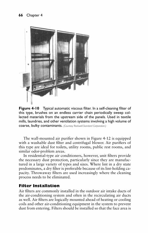
P1: GDZ/FFX P2: GDZ/FFX QC: GDZ/FFX T1: GDZ
GB076-04 GB076-Miller-Sample July 15, 2004 16:53 Char Count= 0
66 Chapter 4
Figure 4-10 Typical automatic viscous filter. In a self-cleaning filter ofthis type, brushes on an endless carrier chain periodically sweep col-lected materials from the upstream side of the panels. Used in textilemills, laundries, and other ventilation systems involving a high volume ofcoarse, bulky contaminants. (Courtesy Rockwell-Standard Corporation.)
The wall-mounted air purifier shown in Figure 4-12 is equippedwith a washable dust filter and centrifugal blower. Air purifiers ofthis type are ideal for toilets, utility rooms, public rest rooms, andsimilar odor-problem areas.
In residential-type air conditioners, however, unit filters providethe necessary dust protection, particularly since they are manufac-tured in a large variety of types and sizes. Where lint in a dry statepredominates, a dry filter is preferable because of its lint-holding ca-pacity. Throwaway filters are used increasingly where the cleaningprocess needs to be eliminated.
Filter InstallationAir filters are commonly installed in the outdoor air intake ducts ofthe air-conditioning system and often in the recirculating air ductsas well. Air filters are logically mounted ahead of heating or coolingcoils and other air-conditioning equipment in the system to preventdust from entering. Filters should be installed so that the face area is

P1: GDZ/FFX P2: GDZ/FFX QC: GDZ/FFX T1: GDZ
GB076-04 GB076-Miller-Sample July 15, 2004 16:53 Char Count= 0
Ventilation Requirements 67
Figure 4-11 Cylindrical-typecanister air purifier.(Courtesy Barneby Cheney Corporation.)
Figure 4-12 Wall-mountedair purifier.(Courtesy Barneby Cheney Corporation.)
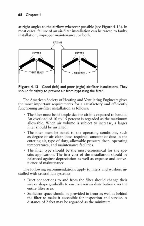
P1: GDZ/FFX P2: GDZ/FFX QC: GDZ/FFX T1: GDZ
GB076-04 GB076-Miller-Sample July 15, 2004 16:53 Char Count= 0
68 Chapter 4
at right angles to the airflow wherever possible (see Figure 4-13). Inmost cases, failure of an air-filter installation can be traced to faultyinstallation, improper maintenance, or both.
CASING
FILTERS FILTERS
TIGHT SEALS AIR LEAKS
Figure 4-13 Good (left) and poor (right) air-filter installations. Theyshould fit tightly to prevent air from bypassing the filter.
The American Society of Heating and Ventilating Engineers givesthe most important requirements for a satisfactory and efficientlyfunctioning air-filter installation as follows:� The filter must be of ample size for air it is expected to handle.
An overload of 10 to 15 percent is regarded as the maximumallowable. When air volume is subject to increase, a largerfilter should be installed.� The filter must be suited to the operating conditions, such
as degree of air cleanliness required, amount of dust in theentering air, type of duty, allowable pressure drop, operatingtemperatures, and maintenance facilities.� The filter type should be the most economical for the spe-
cific application. The first cost of the installation should bebalanced against depreciation as well as expense and conve-nience of maintenance.
The following recommendations apply to filters and washers in-stalled with central fan systems:� Duct connections to and from the filter should change their
size or shape gradually to ensure even air distribution over theentire filter area.� Sufficient space should be provided in front as well as behind
the filter to make it accessible for inspection and service. Adistance of 2 feet may be regarded as the minimum.

P1: GDZ/FFX P2: GDZ/FFX QC: GDZ/FFX T1: GDZ
GB076-04 GB076-Miller-Sample July 15, 2004 16:53 Char Count= 0
Ventilation Requirements 69
� Access doors of convenient size should be provided in thesheet-metal connections leading to and from the filters.� All doors on the clean-air side should be lined with felt
to prevent infiltration of unclean air. All connections andseams of the sheet-metal ducts on the clean-air side should beairtight.� Electric lights should be installed in the chamber in front of
and behind the air filter.� Air washers should be installed between the tempering and
heating coils to protect them from extreme cold in winter.� Filters installed close to air inlets should be protected from the
weather by suitable louvers, in front of which a large-meshwire screen should be provided.� Filters should have permanent indicators to give a warning
when the filter resistance reaches too high a value.
Humidity-Control MethodsHumidifiers, by definition, are devices for adding moisture to the air.Thus, to humidify is to increase the density of water vapor within agiven space or room. Air humidification is affected by vaporizationof water and always requires heat for its proper functioning. Thus,devices that function to add moisture to the air are termed humidi-fiers, whereas devices that function to remove moisture from the airare termed dehumidifiers.
HumidifiersAs previously noted, air humidification consists of adding mois-ture. Following are the types of humidifiers used in air-conditioningsystems:� Spray-type air washers� Pan evaporative humidifiers� Electrically operated humidifiers� Air-operated humidifiers
Air-Washer MethodAn air washer essentially consists of a row of spray nozzles inside achamber or casing. A tank at the bottom of the chamber providesfor collection of water as it falls through the air and comes intointimate contact with the wet surface of the chamber baffles. Thewater is generally circulated by means of a pump, the warm water
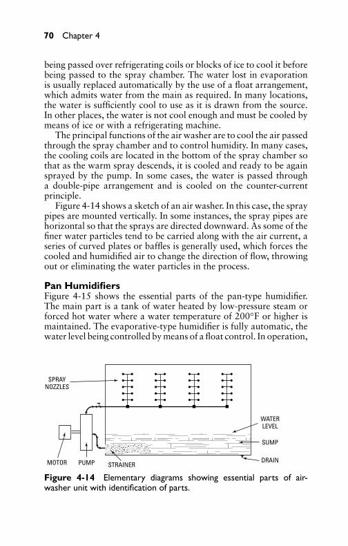
P1: GDZ/FFX P2: GDZ/FFX QC: GDZ/FFX T1: GDZ
GB076-04 GB076-Miller-Sample July 15, 2004 16:53 Char Count= 0
70 Chapter 4
being passed over refrigerating coils or blocks of ice to cool it beforebeing passed to the spray chamber. The water lost in evaporationis usually replaced automatically by the use of a float arrangement,which admits water from the main as required. In many locations,the water is sufficiently cool to use as it is drawn from the source.In other places, the water is not cool enough and must be cooled bymeans of ice or with a refrigerating machine.
The principal functions of the air washer are to cool the air passedthrough the spray chamber and to control humidity. In many cases,the cooling coils are located in the bottom of the spray chamber sothat as the warm spray descends, it is cooled and ready to be againsprayed by the pump. In some cases, the water is passed througha double-pipe arrangement and is cooled on the counter-currentprinciple.
Figure 4-14 shows a sketch of an air washer. In this case, the spraypipes are mounted vertically. In some instances, the spray pipes arehorizontal so that the sprays are directed downward. As some of thefiner water particles tend to be carried along with the air current, aseries of curved plates or baffles is generally used, which forces thecooled and humidified air to change the direction of flow, throwingout or eliminating the water particles in the process.
Pan HumidifiersFigure 4-15 shows the essential parts of the pan-type humidifier.The main part is a tank of water heated by low-pressure steam orforced hot water where a water temperature of 200◦F or higher ismaintained. The evaporative-type humidifier is fully automatic, thewater level being controlled by means of a float control. In operation,
STRAINERPUMPMOTOR
SPRAYNOZZLES
DRAIN
SUMP
WATERLEVEL
Figure 4-14 Elementary diagrams showing essential parts of air-washer unit with identification of parts.

P1: GDZ/FFX P2: GDZ/FFX QC: GDZ/FFX T1: GDZ
GB076-04 GB076-Miller-Sample July 15, 2004 16:53 Char Count= 0
Ventilation Requirements 71
when the relative humidity drops below the humidity-control set-ting, the humidifier fan blows air over the surface of the heatedwater in the tank. The air picks up moisture. The air is blown to thespace to be humidified. When the humidity control is satisfied, thehumidifier fan stops.
Figure 4-15 Typical evaporative pan humidifier showing operativecomponents. (Courtesy Armstrong Machine Works.)
Electrically Operated HumidifiersDry-steam electrically operated humidifiers operate by means of asolenoid valve, which is energized by a humidistat. When the relativehumidity drops slightly below the desired level set by the humidistat(see Figure 4-16), a solenoid valve actuated by the humidistat admitssteam from the separating chamber to the re-evaporating chamber.Steam passes from this chamber through the muffler directly to theatmosphere. The fan (which is energized when the solenoid valveopens) assists in dispersing the steam into the area to be humidified.When the relative humidity reaches the desired level, the humidistatcloses the solenoid valve and stops the fan.
Air-Operated HumidifiersAir-operated humidifying units operate in the same manner as elec-trical units, except that they utilize a pneumatic hygrostat as a hu-midity controller and an air operator to open or close the steamvalve (see Figure 4-17). A decrease in relative humidity increases
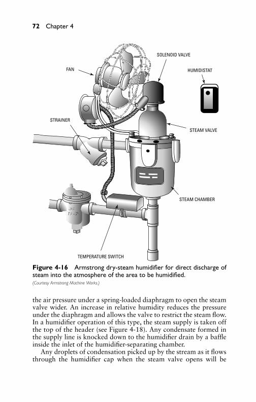
P1: GDZ/FFX P2: GDZ/FFX QC: GDZ/FFX T1: GDZ
GB076-04 GB076-Miller-Sample July 15, 2004 16:53 Char Count= 0
72 Chapter 4
STRAINER
FAN
SOLENOID VALVE
HUMIDISTAT
STEAM VALVE
STEAM CHAMBER
TEMPERATURE SWITCH
Figure 4-16 Armstrong dry-steam humidifier for direct discharge ofsteam into the atmosphere of the area to be humidified.(Courtesy Armstrong Machine Works.)
the air pressure under a spring-loaded diaphragm to open the steamvalve wider. An increase in relative humidity reduces the pressureunder the diaphragm and allows the valve to restrict the steam flow.In a humidifier operation of this type, the steam supply is taken offthe top of the header (see Figure 4-18). Any condensate formed inthe supply line is knocked down to the humidifier drain by a baffleinside the inlet of the humidifier-separating chamber.
Any droplets of condensation picked up by the stream as it flowsthrough the humidifier cap when the steam valve opens will be

P1: GDZ/FFX P2: GDZ/FFX QC: GDZ/FFX T1: GDZ
GB076-04 GB076-Miller-Sample July 15, 2004 16:53 Char Count= 0
Ventilation Requirements 73
SEPARATOR
STAINLESS STEEL JACKETEDSTEAM DISTRIBUTION MANIFOLD
MODULATING AIR ORELECTRIC MOTOR OPERATOR
Figure 4-17 Armstrong dry-steam humidifier with steam-jacket dis-tribution.
thrown to the bottom of the re-evaporating chamber. Pressure in thischamber is essentially atmospheric. Since it is surrounded by steamat supply pressure and temperature, any water is re-evaporated toprovide dry steam at the outlet. The humidifier outlet is also sur-rounded by steam at supply pressure to ensure that there will be nocondensation or drip at this point. A clamp-on temperature switch isattached to the condensate drain line to prevent the electric or pneu-matic operator from opening the steam valve until the humidifier isup to steam temperature.
DehumidifiersThe removal of moisture from the air is termed dehumidification. Airdehumidification is accomplished by one of two methods: coolingand adsorption. Dehumidification can be accomplished by an airwasher, providing the temperature of the spray is lower than thedew point of the air passing through the unit. If the temperature ofthe spray is higher than the dew point, condensation will not takeplace. Air washers having refrigerated sprays usually have their ownrecirculating pump.
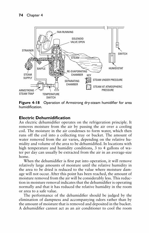
P1: GDZ/FFX P2: GDZ/FFX QC: GDZ/FFX T1: GDZ
GB076-04 GB076-Miller-Sample July 15, 2004 16:53 Char Count= 0
74 Chapter 4
STRAINER
STEAMSUPPLY
ARMSTRONGSTEAM TRAP TEMPERATURE
SWITCH
BAFFLE
SEPARATINGCHAMBER
RE-EVAPORATINGCHAMBER KEY
STEAM UNDER PRESSURE
STEAM AT ATMOSPHERICPRESSURE
HUMIDISTAT
SWITCH
FAN RUNNING
SOLENOIDVALVE OPEN
STEAM
Figure 4-18 Operation of Armstrong dry-steam humidifier for areahumidification.
Electric DehumidificationAn electric dehumidifier operates on the refrigeration principle. Itremoves moisture from the air by passing the air over a coolingcoil. The moisture in the air condenses to form water, which thenruns off the coil into a collecting tray or bucket. The amount ofwater removed from the air varies, depending on the relative hu-midity and volume of the area to be dehumidified. In locations withhigh temperature and humidity conditions, 3 to 4 gallons of wa-ter per day can usually be extracted from the air in an average-sizehome.
When the dehumidifier is first put into operation, it will removerelatively large amounts of moisture until the relative humidity inthe area to be dried is reduced to the value where moisture dam-age will not occur. After this point has been reached, the amount ofmoisture removed from the air will be considerably less. This reduc-tion in moisture removal indicates that the dehumidifier is operatingnormally and that it has reduced the relative humidity in the roomor area to a safe value.
The performance of the dehumidifier should be judged by theelimination of dampness and accompanying odors rather than bythe amount of moisture that is removed and deposited in the bucket.A dehumidifier cannot act as an air conditioner to cool the room
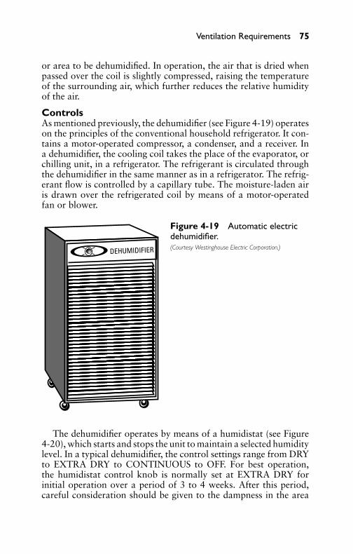
P1: GDZ/FFX P2: GDZ/FFX QC: GDZ/FFX T1: GDZ
GB076-04 GB076-Miller-Sample July 15, 2004 16:53 Char Count= 0
Ventilation Requirements 75
or area to be dehumidified. In operation, the air that is dried whenpassed over the coil is slightly compressed, raising the temperatureof the surrounding air, which further reduces the relative humidityof the air.
ControlsAs mentioned previously, the dehumidifier (see Figure 4-19) operateson the principles of the conventional household refrigerator. It con-tains a motor-operated compressor, a condenser, and a receiver. Ina dehumidifier, the cooling coil takes the place of the evaporator, orchilling unit, in a refrigerator. The refrigerant is circulated throughthe dehumidifier in the same manner as in a refrigerator. The refrig-erant flow is controlled by a capillary tube. The moisture-laden airis drawn over the refrigerated coil by means of a motor-operatedfan or blower.
DEHUMIDIFIER
Figure 4-19 Automatic electricdehumidifier.(Courtesy Westinghouse Electric Corporation.)
The dehumidifier operates by means of a humidistat (see Figure4-20), which starts and stops the unit to maintain a selected humiditylevel. In a typical dehumidifier, the control settings range from DRYto EXTRA DRY to CONTINUOUS to OFF. For best operation,the humidistat control knob is normally set at EXTRA DRY forinitial operation over a period of 3 to 4 weeks. After this period,careful consideration should be given to the dampness in the area
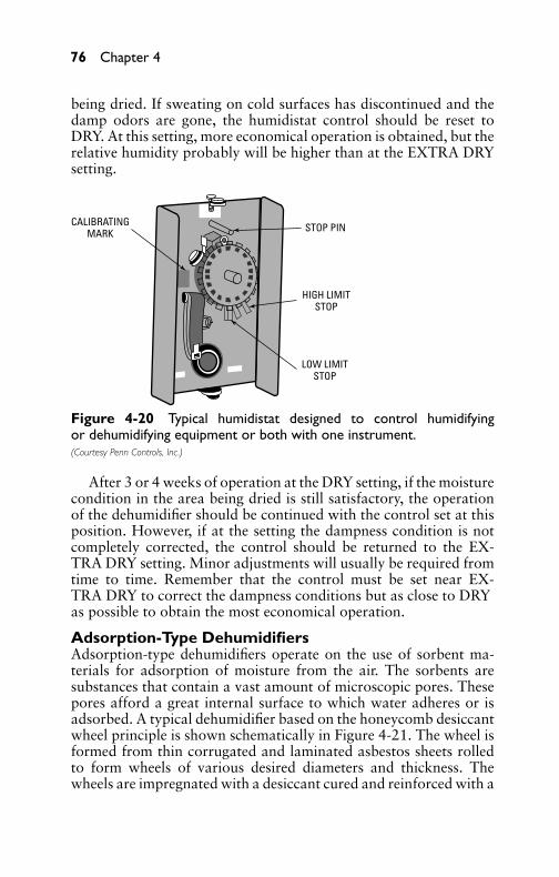
P1: GDZ/FFX P2: GDZ/FFX QC: GDZ/FFX T1: GDZ
GB076-04 GB076-Miller-Sample July 15, 2004 16:53 Char Count= 0
76 Chapter 4
being dried. If sweating on cold surfaces has discontinued and thedamp odors are gone, the humidistat control should be reset toDRY. At this setting, more economical operation is obtained, but therelative humidity probably will be higher than at the EXTRA DRYsetting.
CALIBRATINGMARK STOP PIN
HIGH LIMITSTOP
LOW LIMITSTOP
Figure 4-20 Typical humidistat designed to control humidifyingor dehumidifying equipment or both with one instrument.(Courtesy Penn Controls, Inc.)
After 3 or 4 weeks of operation at the DRY setting, if the moisturecondition in the area being dried is still satisfactory, the operationof the dehumidifier should be continued with the control set at thisposition. However, if at the setting the dampness condition is notcompletely corrected, the control should be returned to the EX-TRA DRY setting. Minor adjustments will usually be required fromtime to time. Remember that the control must be set near EX-TRA DRY to correct the dampness conditions but as close to DRYas possible to obtain the most economical operation.
Adsorption-Type DehumidifiersAdsorption-type dehumidifiers operate on the use of sorbent ma-terials for adsorption of moisture from the air. The sorbents aresubstances that contain a vast amount of microscopic pores. Thesepores afford a great internal surface to which water adheres or isadsorbed. A typical dehumidifier based on the honeycomb desiccantwheel principle is shown schematically in Figure 4-21. The wheel isformed from thin corrugated and laminated asbestos sheets rolledto form wheels of various desired diameters and thickness. Thewheels are impregnated with a desiccant cured and reinforced with a

P1: GDZ/FFX P2: GDZ/FFX QC: GDZ/FFX T1: GDZ
GB076-04 GB076-Miller-Sample July 15, 2004 16:53 Char Count= 0
Ventilation Requirements 77
heat-resistant binder. The corrugations in the honeycomb wheelform narrow flutes perpendicular to the wheel diameter. Approx-imately 75 percent of the wheel face area is available for the adsorp-tion or dehumidifying flow circuit, and 25 percent is available forthe reactivation circuit. In the smaller units, the reactivated air isheated electrically; in the larger units, it is heated by electric, steam,or gas heaters.
REACTIVATIONAIR INLET FILTER
HUMIDAIR
INLETFILTER
REACTIVATIONAIR HEATER
HONEYCOMB DESICCANT WHEEL
REACTIVATIONSECTOR
ROLLS ANDDRIVE MOTOR
WET AIR OUTLET
REACTIVATIONFAN
DRY AIR OUTLET
DRY AIR FAN
Figure 4-21 Assembly of components operating on the honeycombmethod of dehumidification. (Courtesy Cargocaire Engineering Corporation.)
Figure 4-22 shows another industrial adsorbent dehumidifier ofthe stationary-bed type. It has two sets of stationary adsorbing bedsarranged so that one set is dehumidifying the air while the other setis drying. With the dampers in the position shown, air to be driedflows through one set of beds and is dehumidified while the dryingair is heated and circulated through the other set. After completionof drying, the beds are cooled by shutting off the drying air heatersand allowing unheated air to circulate through them. An automatictimer controller is provided to allow the dampers to rotate to theopposite side when the beds have adsorbed moisture to a degree thatbegins to impair performance.
Air-Duct SystemsAir ducts for transmission of air in a forced-air heating, ventila-tion, or air-conditioner system must be carefully designed from the
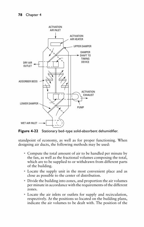
P1: GDZ/FFX P2: GDZ/FFX QC: GDZ/FFX T1: GDZ
GB076-04 GB076-Miller-Sample July 15, 2004 16:53 Char Count= 0
78 Chapter 4
ACTIVATIONAIR INLET
ACTIVATIONAIR HEATER
UPPER DAMPER
DAMPERSHAFT TO
TIMINGDEVICE
ACTIVATION EXHAUST
PUMP
WET AIR INLET
LOWER DAMPER
ADSORBER BEDS
DRY AIROUTLET
Figure 4-22 Stationary bed–type solid-absorbent dehumidifier.
standpoint of economy, as well as for proper functioning. Whendesigning air ducts, the following methods may be used:
� Compute the total amount of air to be handled per minute bythe fan, as well as the fractional volumes composing the total,which are to be supplied to or withdrawn from different partsof the building.� Locate the supply unit in the most convenient place and as
close as possible to the center of distribution.� Divide the building into zones, and proportion the air volumes
per minute in accordance with the requirements of the differentzones.� Locate the air inlets or outlets for supply and recirculation,
respectively. At the positions so located on the building plans,indicate the air volumes to be dealt with. The position of the

P1: GDZ/FFX P2: GDZ/FFX QC: GDZ/FFX T1: GDZ
GB076-04 GB076-Miller-Sample July 15, 2004 16:53 Char Count= 0
Ventilation Requirements 79
outlets and inlets should be such as to produce a thoroughdiffusion of the conditioned air throughout the space supplied.� Determine the size of each outlet or inlet based on passing the
required amount of air per minute at a suitable velocity.� Calculate the areas, and select suitable dimensions for all
branch and main ducts. Do this based on creating equal fric-tional losses per foot of length. This involves reducing the ve-locities in smaller ducts.� Ascertain the resistance of the ducts that sets up the greatest
friction. In most cases, this will be the longest run, althoughnot so invariably. This will be the resistance offered by the ductsystem as a whole to the flow of the required amount of air.� Revise the dimensions and areas of the shorter runs so that the
ducts themselves will create resistances equal to the longestrun. This will cut down the cost of the sheet metal, and theresult will be just the same as if dampers were used. Too higha velocity, however, must be avoided.� To compensate for unforeseen contingencies, volume dampers
should be provided for each branch.
Heat Gains in DuctsIn any air-conditioning installation involving a duct system, invari-ably there is an accession of heat by the moving air in the ducts be-tween the coils and supply grilles when air is supplied below roomtemperature. If the ducts are located through much of their lengthin the conditioned space, then, of course, this heat absorption hasno affect on the total load and frequently may be disregarded.
More frequently, however, the supply ducts must pass throughspaces that are not air-conditioned. Under these conditions, the heatabsorbed by the air in the ducts can be regarded as an additional loadon the cooling equipment. The temperature rise in a duct system ofa cooling installation depends on the following factors:� Temperature of the space through which the duct passes� Air velocity through the duct� Type and thickness of insulation, if any
The first factor establishes the temperature differential betweenthe air on either side of the duct walls. The dew point of the airsurrounding the duct may also have some effect on the heat pickup,as condensation on the duct surface gives up the heat of vaporiza-tion to the air passing through the system. The highest air velocities
P1: GDZ/FFX P2: GDZ/FFX QC: GDZ/FFX T1: GDZ
GB076-04 GB076-Miller-Sample July 15, 2004 16:53 Char Count= 0
80 Chapter 4
consistent with the acoustic requirements of the installation shouldbe used, not only for economy in the sheet metal material used, butalso to reduce the heat pickup in the ducts.
The amount of heat absorbed by a unit area of sheet-metal ductconveying chilled air is almost directly proportional to the temper-ature difference between the atmosphere surrounding the duct andthe chilled air, irrespective of the velocity of the latter. The heatpickup rate will be influenced somewhat by the outside finish of theduct and by the air motion, if any, in the space through which theduct passes.
Heat leakage in Btu per hour per square foot per degree differ-ence in temperature for uncovered galvanized iron ductwork willbe between 0.5 and 1.0, with an average value of 0.73. The rate ofleakage, of course, will be greatest at the start of the duct run andwill gradually diminish as the air temperature rises. Covering theduct with the equivalent of 1/2-inch rigid insulation board and seal-ing cracks with tape will reduce the average rate of heat pickup persquare foot of surface per hour to 0.23 Btu per degree difference.
To summarize, the designer of a central unit system should ob-serve the following:
� Locate the equipment as close to the conditioned space as pos-sible.� Use duct velocities as high as practical, considering the acoustic
level of the space and operating characteristics of the fans.� Insulate all supply ducts with covering equivalent to at least
1/2 inch of rigid insulation, and seal cracks with tape.
Suitable Duct VelocitiesTable 4-2 gives the recommended air velocities in feet per minute fordifferent requirements. These air velocities are in accordance withgood practice. It should be understood that the fan-outlet velocitiesdepend somewhat on the static pressure, as static pressures and fan-housing-velocity pressures are interdependent for good operatingconditions. Fan-outlet velocities are also affected by the particulartype of fan installed.
Air-Duct CalculationsFor the sake of convenience, this section outlines a simplified air-duct sizing procedure, which eliminates the usual complicated en-gineering calculation required when designing a duct system. Referto Figures 4-23 to 4-25, which show the plans of a typical familyresidence having a total cubic content of approximately 19,000 ft3.
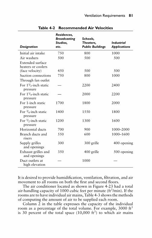
P1: GDZ/FFX P2: GDZ/FFX QC: GDZ/FFX T1: GDZ
GB076-04 GB076-Miller-Sample July 15, 2004 16:53 Char Count= 0
Ventilation Requirements 81
Table 4-2 Recommended Air Velocities
Residences,Broadcasting Schools,Studios, Theaters, Industrial
Designation etc. Public Buildings Applications
Initial air intake 750 800 1000Air washers 500 500 500Extended surfaceheaters or coolers(face velocity) 450 500 500Suction connections 750 800 1000Through fan outletFor 11/2-inch static — 2200 2400
pressureFor 11/4-inch static — 2000 2200
pressureFor 1-inch static 1700 1800 2000
pressureFor 3/4-inch static 1400 1550 1800
pressureFor 1/2-inch static 1200 1300 1600
pressureHorizontal ducts 700 900 1000–2000Branch ducts and 550 600 1000–1600
risersSupply grilles 300 300 grille 400 opening
and openingsExhaust grilles and 350 400 grille 500 opening
and openingsDuct outlets at — 1000 —
high elevation
It is desired to provide humidification, ventilation, filtration, and airmovement to all rooms on both the first and second floors.
The air conditioner located as shown in Figure 4-23 had a totalair-handling capacity of 1000 cubic feet per minute (ft3/min). If therooms are to have individual air mains, Table 4-3 shows the methodsof computing the amount of air to be supplied each room.
Column 2 in the table expresses the capacity of the individualroom as a percentage of the total volume. For example, 3000 ft3
is 30 percent of the total space (10,000 ft3) to which air mains

P1: GDZ/FFX P2: GDZ/FFX QC: GDZ/FFX T1: GDZ
GB076-04 GB076-Miller-Sample July 15, 2004 16:53 Char Count= 0
82 Chapter 4
D = DIRECTIONAL FLOW DAMPERWITH QUADRANT AND SETSCREEN
VD = VOLUME DAMPER WITHQUADRANT AND SETSCREEN
1000 CFMFULL-SIZE OUTLET
1000 CFM42" × 13"
GRILLE
AIRCONDITIONER
ACCESSDOOR
FRESH AIR INLET 16" × 6" WITH FIXED LOUVREAND 1/4" COPPERWIRE MESH SCREENING
300 CFM400'V
700 CFM550'V
450 CFM700'V
350 CFM600'V
150 CFM600'V
550 CFM700'V
300 CFM600'V
150 CFM600'V
150 CFM550'V
200 CFM600'V
200 CFM600'V
TO 2ND FLTO CHAMBER
#1
12" × 5"
16" × 6"
8" × 6"
42" ×61/2"
10"
× 3"
= 16" × 6"= 30" × 6"
14" × 6"
= 19" × 6"
= 10" × 31/2" 1
0" ×
31 / 2"
TO LIVINGROOM
TO 2ND FL
TO 2ND FL
INSULATE AIR MAINSIN THIS SPACE
UNEXCAVATED
10" × 3"
10" × 3"
DD
D
VD
D
8" ×
6"
D
Figure 4-23 Basement floor of a typical family residence showing air-conditioner and heat-duct layout.
will lead. Column 3 indicates the cubic feet of air per minute tobe supplied to the individual rooms. These figures are attained asfollows. The air conditioner will handle 1000 ft3 of air per minute;30 percent of this is 300 ft3/min. Similarly, 10 percent is 100 ft3/min,which would indicate the quantity of air to be supplied to the livingroom and chamber No. 3, respectively. Having thus established theair quantity to be delivered to each of the rooms, the design of theducts can now be considered.
For duct sizes, consider the branch duct to both the living roomand chamber No. 1 (see Table 4-3). Note that the branch leadinginto chamber No. 1 handles 150 ft3/min. The duct to the livingroom handles 300 ft3/min. Obviously, the connecting air main willhandle 300 + 150, or 450, ft3/min, in accordance with the foregoingrecommendation, allowing a velocity of 600 ft/min for the branchesand 700 ft/min for the supply air main. Therefore, the necessaryduct areas can be calculated using the following formula:
a × 144 (in2/ft2)b

P1: GDZ/FFX P2: GDZ/FFX QC: GDZ/FFX T1: GDZ
GB076-04 GB076-Miller-Sample July 15, 2004 16:53 Char Count= 0
Ventilation Requirements 83
TO SECOND FLOOR
LIVING ROOM3000 ft3
DINING ROOM13'-6" × 16'-0"
2000 ft3
TO SECOND FLOOR
TO SECOND FLOOR10" × 3"
FLOOR REGISTER10" × 5"
STUDY10'-0" × 11'-0"
1000 ft3
FLOOR REGISTER12" × 12"
FLOOR GRILLE30" × 10"
FLOOR REGISTER12" × 8"
KITCHEN11'-6" × 11'-0"
HALL
CLOS.
FRESH AIR INLET GRILLECEILING HEIGHT
9'-0"
10" × 31/2"
10" × 31/2"
Figure 4-24 First-floor layout of residence of Figure 4-23. Vertical airdischarges are located in the floor of the living room, dining room, andstudy. Air is returned to the unit through the floor grilles in the entrancehall. Sizes for air mains are shown on the basement plan.
where the following is true:
a = necessary air supply to room, ft3/minb = recommended velocity for a main or branch
Living-room (300 ft3/min) branch:
300 × 144600
= 72 in2 = 12 × 6 in branch
Chamber No. 1 (150 ft3/min) branch:
150 × 144600
= 36 in2 = 10 × 31/2 in branch

P1: GDZ/FFX P2: GDZ/FFX QC: GDZ/FFX T1: GDZ
GB076-04 GB076-Miller-Sample July 15, 2004 16:53 Char Count= 0
84 Chapter 4
BASEBOARDREGISTER
14" × 6"
BASEBOARDREGISTER
14" × 6"
BASEBOARDREGISTER
12" × 5"
CHAMBER #113'-0" × 15'-0"
1500 ft3
CHAMBER #213'-6" × 15'-0"
1500 ft3
CHAMBER #311'-0" × 13'-6"
1000 ft3
CEILING HEIGHT7' × 6"
CLOSET CLOSET
CLOSET
CLOSETBATH
BATH
HALL
Figure 4-25 Second-floor layout of residence of Figures 4-23 and4-24. Air discharges are located in the basement of the three chambers.
Total (450 ft3/min) main:
450 × 144700
= 93 in2 = 16 × 6 in main
The remaining duct work may be calculated similarly. It is rec-ommended that the main air supply leaving the unit be the same size
Table 4-3 Air-Duct Calculation
Room % of Supply,Rooms Volume, ft3 Total Volume ft3/min
First floor Living room 3000 30 300Dining room 2000 20 200Study 1000 10 100
Second floor Chamber No. 1 1500 15 150Chamber No. 2 1500 15 150Chamber No. 3 1000 10 100Total volume 10,000 100 1000
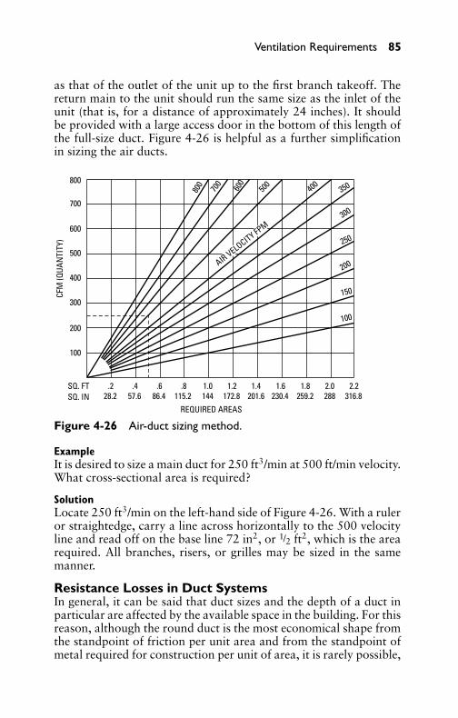
P1: GDZ/FFX P2: GDZ/FFX QC: GDZ/FFX T1: GDZ
GB076-04 GB076-Miller-Sample July 15, 2004 16:53 Char Count= 0
Ventilation Requirements 85
as that of the outlet of the unit up to the first branch takeoff. Thereturn main to the unit should run the same size as the inlet of theunit (that is, for a distance of approximately 24 inches). It shouldbe provided with a large access door in the bottom of this length ofthe full-size duct. Figure 4-26 is helpful as a further simplificationin sizing the air ducts.
SQ. FTSQ. IN
.228.2 57.6 86.4 115.2 144 172.8 201.6 230.4 259.2 288 316.8
.4 .6 .8 1.0 1.2 1.4 1.6 1.8 2.0 2.2
800
800
70070
0600
600
500
500
400
400
300
350
300
250
200
150
100200
100
REQUIRED AREAS
CFM
(QUA
NTI
TY)
AIR VELOCITY FPM
Figure 4-26 Air-duct sizing method.
ExampleIt is desired to size a main duct for 250 ft3/min at 500 ft/min velocity.What cross-sectional area is required?
SolutionLocate 250 ft3/min on the left-hand side of Figure 4-26. With a ruleror straightedge, carry a line across horizontally to the 500 velocityline and read off on the base line 72 in2, or 1/2 ft2, which is the arearequired. All branches, risers, or grilles may be sized in the samemanner.
Resistance Losses in Duct SystemsIn general, it can be said that duct sizes and the depth of a duct inparticular are affected by the available space in the building. For thisreason, although the round duct is the most economical shape fromthe standpoint of friction per unit area and from the standpoint ofmetal required for construction per unit of area, it is rarely possible,

P1: GDZ/FFX P2: GDZ/FFX QC: GDZ/FFX T1: GDZ
GB076-04 GB076-Miller-Sample July 15, 2004 16:53 Char Count= 0
86 Chapter 4
except in industrial buildings, to use round ducts largely. Squareduct is the preferable shape among those of rectangular crosssection. Headroom limitations usually require that the duct beflattened.
To illustrate the use of charts when sizing a duct system, considerthe following example.
ExampleAssume a system requiring the delivery of 5000 ft3/min. The distri-bution requirement is the movement of the entire volume a distanceof approximately 80 ft, with the longest branch beyond that pointconveying 1000 ft3/min for an additional 70 feet. Assume furtherthat the operating characteristics of the fan and the resistance ofthe coils, filters, and so on, allow a total supply-duct resistance of0.10-inch water-gage resistance pressure. The supply duct is not tobe more than 12 inches deep.
SolutionThe total length of the longest run is 80 + 70 = 150 feet:
100150
× 0.10 = 0.067-inch water gage
Starting at this resistance at the bottom of Figure 4-27, fol-low upward to the horizontal line representing 5000 ft3/min. Atthis point, read the equivalent size of round duct required that isapproximately 28 inches in diameter. Move diagonally upward tothe right on the 28-inch-diameter line, and then across horizon-tally on this line in Figure 4-27 to the vertical line representing the12-inch side of a rectangular duct. At this point, read 60 inches asthe width of the rectangular duct required on the intersecting curveline.
Thus, for the main duct run, the duct size will be 60 × 12 inches.For the branch conveying 1000 ft3/min, from the point where the0.067-inch resistance line intersects the 1000-ft3/min line, read16 inches as the equivalent round duct required. Following throughon Figure 4-27 as for a larger duct, read 12 × 18 inches as the sizeof the branch duct.
Duct runs should take into account the number of bends and off-sets. Obstructions of this kind are usually represented in terms of theequivalent length of straight duct necessary to produce the same re-sistance value. Where conditions require sharp or right-angle bends,vane elbows composed of a number of curved deflectors across theair-stream should be used.

P1: GDZ/FFX P2: GDZ/FFX QC: GDZ/FFX T1: GDZ
GB076-04 GB076-Miller-Sample July 15, 2004 16:53 Char Count= 0
Ventilation Requirements 87CU
BIC
FEET
PER
MIN
UTE
FRICTION IN INCHES WATER GAGE PER 100 FEET
100
150
200
300
400500600
800
1000
2000
3000
4000500060008000
000
20,000
30,000
40,00050,00060,000
80,000
100,000
200,000
300,000
400,000500,000600,000
800,0001,000,000
.02 .03 .04 .05.06 .08 .1 .2 .3 .4 .5 .8 1 2 3 4 5 6 8 1
.02 .03 .04 .05.06 .08 .1 .2 .3 .4 .6 .8 1 2 3 4 5 6 8 10
75"70"65"60"55"
50"
45"
40"38"36"34"32"30"28"26"24"22"
20"
18"
16"
14"
12"
10"
9"
8"
7"
6"
5"
4"
VELOCITY-FEETPER
MINUTE
140" DIAMETER OF DUCT
120"
110"
100"
90"
80"
75"70"
60"
55"
50"
45"
40"38"
34"36"
32"30"
28"26"
24"
18"20"22"
16"
14"
12"
10"
9 "
8 "
7"
6 "
5"
4"
18,000
10,000
10001100
12001400
1600
20001800
22002400
26002800
32003000
36004000
45005000
55006000
65007000
80009000
500
600700
800900
Figure 4-27 Graphic representation of air-duct areas.

P1: GDZ/FFX P2: GDZ/FFX QC: GDZ/FFX T1: GDZ
GB076-04 GB076-Miller-Sample July 15, 2004 16:53 Char Count= 0
88 Chapter 4
WIDTH OF RECTANGULAR DUCT IN INCHES
EQUI
VALE
NT
DIAM
ETER
OF
ROUN
D DU
CT
4 5 6 8 97 10 12 15 20 30 35 40 45 50 55 60 65 70 75 80
4" 5" 6" 8" 9"7" 10" 12" 15" 20" 25" 30" 35" 40" 45" 50" 55" 60" 65" 70" 75" 80"
75"70"65"60"55"
50"
45"
40"38"36"34"32"30"28"26"24"22"
20"
18"
16"
14"
12"
10"
9"
8"
7"
6"
5"
4"
ONE SIDE OF RECTANGULAR DUCT72"
60" 54"
48"42"
36"32"
28"24"
20"18"
16"
14"
12"11"
10"9"8"7"
6"
5"
66"
Figure 4-27 (continued)
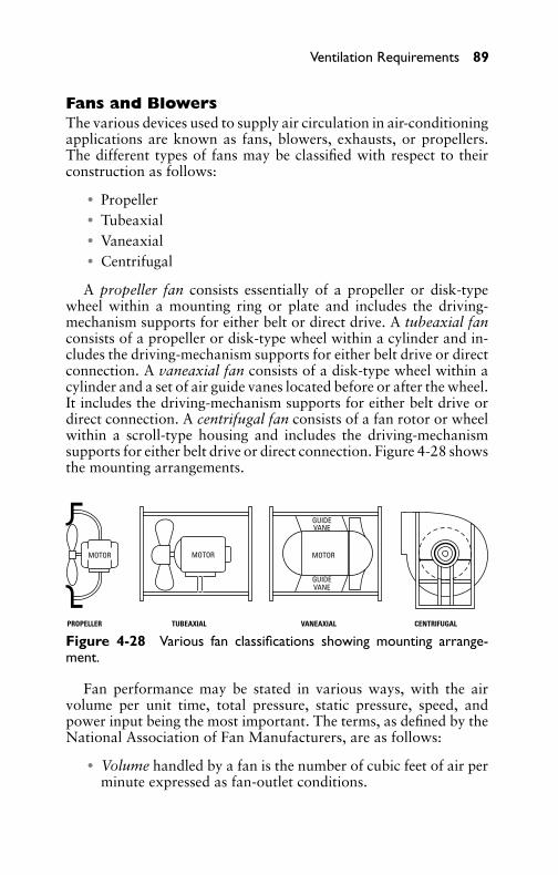
P1: GDZ/FFX P2: GDZ/FFX QC: GDZ/FFX T1: GDZ
GB076-04 GB076-Miller-Sample July 15, 2004 16:53 Char Count= 0
Ventilation Requirements 89
Fans and BlowersThe various devices used to supply air circulation in air-conditioningapplications are known as fans, blowers, exhausts, or propellers.The different types of fans may be classified with respect to theirconstruction as follows:
� Propeller� Tubeaxial� Vaneaxial� Centrifugal
A propeller fan consists essentially of a propeller or disk-typewheel within a mounting ring or plate and includes the driving-mechanism supports for either belt or direct drive. A tubeaxial fanconsists of a propeller or disk-type wheel within a cylinder and in-cludes the driving-mechanism supports for either belt drive or directconnection. A vaneaxial fan consists of a disk-type wheel within acylinder and a set of air guide vanes located before or after the wheel.It includes the driving-mechanism supports for either belt drive ordirect connection. A centrifugal fan consists of a fan rotor or wheelwithin a scroll-type housing and includes the driving-mechanismsupports for either belt drive or direct connection. Figure 4-28 showsthe mounting arrangements.
PROPELLER TUBEAXIAL VANEAXIAL CENTRIFUGAL
GUIDE
MOTORMOTOR MOTOR
VANE
GUIDEVANE
Figure 4-28 Various fan classifications showing mounting arrange-ment.
Fan performance may be stated in various ways, with the airvolume per unit time, total pressure, static pressure, speed, andpower input being the most important. The terms, as defined by theNational Association of Fan Manufacturers, are as follows:
� Volume handled by a fan is the number of cubic feet of air perminute expressed as fan-outlet conditions.

P1: GDZ/FFX P2: GDZ/FFX QC: GDZ/FFX T1: GDZ
GB076-04 GB076-Miller-Sample July 15, 2004 16:53 Char Count= 0
90 Chapter 4
� Total pressure of a fan is the rise of pressure from fan inlet tofan outlet.� Velocity pressure of a fan is the pressure corresponding to the
average velocity determination from the volume of air-flow atthe fan outlet area.� Static pressure of a fan is the total pressure diminished by the
fan-velocity pressure.� Power output of a fan is expressed in horsepower and is based
on fan volume and the fan total pressure.� Power input of a fan is expressed in horsepower and is mea-
sured as horsepower delivered to the fan shaft.� Mechanical efficiency of a fan is the ratio of power output to
power input.� Static efficiency of a fan is the mechanical efficiency multiplied
by the ratio of static pressure to the total pressure.� Fan-outlet area is the inside area of the fan outlet.� Fan-inlet area is the inside area of the inlet collar.
Air VolumeThe volume of air required is determined by the size of the space tobe ventilated and the number of times per hour that the air in thespace is to be changed. Table 4-4 shows the recommended rate ofair change for various types of spaces.
In many cases, existing local regulations or codes will govern theventilating requirements. Some of these codes are based on a spec-ified amount of air per person and on the air required per squarefoot of floor area. Table 4-4 should serve as a guide to average con-ditions. Where local codes or regulations are involved, they shouldbe taken into consideration. If the number of persons occupying thespace is larger than would be normal for such a space, the air shouldbe changed more often than shown.
Horsepower RequirementsThe horsepower required for any fan or blower varies directly as thecube of the speed, provided that the area of the discharge orifice re-mains unchanged. The horsepower requirements of a centrifugal fangenerally decrease with a decrease in the area of the discharge orificeif the speed remains unchanged. The horsepower requirements of apropeller fan increase as the area of the discharge orifice decreasesif the speed remains unchanged.

P1: GDZ/FFX P2: GDZ/FFX QC: GDZ/FFX T1: GDZ
GB076-04 GB076-Miller-Sample July 15, 2004 16:53 Char Count= 0
Ventilation Requirements 91
Table 4-4 Volume of Air Required
Space to Be Ventilated Air Changes per Hour Minutes per Change
Auditoriums 6 10Bakeries 20 3Bowling alleys 12 5Club rooms 12 5Churches 6 10Dining rooms (restaurants) 12 5Factories 10 6Foundries 20 3Garages 12 5Kitchens (restaurants) 30 2Laundries 20 3Machine shops 10 6Offices 10 6Projection booths 60 1Recreation rooms 10 6Sheet-metal shops 10 6Ship holds 6 10Stores 10 6Toilets 20 3Tunnels 6 10
Drive MethodsWhenever possible, the fan wheel should be directly connected to themotor shaft. This can usually be accomplished with small centrifugalfans and with propeller fans up to about 60 inches in diameter. Thedeflection and the critical speed of the shaft, however, should beinvestigated to determine whether or not it is safe.
When selecting a motor for fan operation, it is advisable to selecta standard motor one size larger than the fan requirements. It shouldbe kept in mind, however, that direct-connected fans do not requireas great a safety factor as that of belt-driven units. It is desirable toemploy a belt drive when the required fan speed or horsepower isin doubt, since a change in pulley size is relatively inexpensive if anerror is made (see Figure 4-29).
Directly connected small fans for various applications are usuallydriven by single-phase AC motors of the split-phase, capacitor, orshaded-pole type. The capacitor motor is more efficient electrically

P1: GDZ/FFX P2: GDZ/FFX QC: GDZ/FFX T1: GDZ
GB076-04 GB076-Miller-Sample July 15, 2004 16:53 Char Count= 0
92 Chapter 4
Figure 4-29 Drive and mounting arrangement for various types ofpropeller fans.
and is used in districts where there are current limitations. Suchmotors, however, are usually arranged to operate at one speed. Withsuch a motor, if it is necessary to vary the air volume or pressure ofthe fan or blower, the throttling of air by a damper installation isusually made.
In large installations (such as when mechanical draft fans arerequired), various drive methods are used:
� A slip-ring motor to vary the speed.� A constant-speed, directly connected motor, which, by means
of moveable guide vanes in the fan inlet, serves to regulate thepressure and air volume.
Fan SelectionMost often, the service determines the type of fan to use. When op-eration occurs with little or no resistance, and particularly when noduct system is required, the propeller fan is commonly used becauseof its simplicity and economy in operation. When a duct system isinvolved, a centrifugal or axial type of fan is usually employed. In
P1: GDZ/FFX P2: GDZ/FFX QC: GDZ/FFX T1: GDZ
GB076-04 GB076-Miller-Sample July 15, 2004 16:53 Char Count= 0
Ventilation Requirements 93
general, centrifugal and axial fans are comparable with respect tosound effect, but the axial fans are somewhat lighter and require con-siderably less space. The following information is usually requiredfor proper fan selection:
� Capacity requirement in cubic feet per minute� Static pressure or system resistance� Type of application or service� Mounting arrangement of system� Sound level or use of space to be served� Nature of load and available drive
The various fan manufacturers generally supply tables or charac-teristic curves that ordinarily show a wide range of operating par-ticulars for each fan size. The tabulated data usually include staticpressure, outlet velocity, revolutions per minute, brake horsepower,tip or peripheral speed, and so on.
Fan ApplicationsThe numerous applications of fans in the field of air conditioningand ventilation are well known, particularly to engineers and air-conditioning repair and maintenance personnel. The various fanapplications are as follows:
� Exhaust fans� Circulating fans� Cooling-tower fans� Kitchen fans� Attic fans
Exhaust fans are found in all types of applications, accord-ing to the American Society of Heating and Ventilating Engineers.Wall fans are predominantly of the propeller type, since they op-erate against little or no resistance. They are listed in capacitiesfrom 1000 to 75,000 ft3/min. They are sometimes incorporatedin factory-built penthouses and roof caps or provided with match-ing automatic louvers. Hood exhaust fans involving ductwork arepredominantly centrifugal, especially in handling hot or corrosivefumes.
Spray-booth exhaust fans are frequently centrifugal, especiallyif built into self-contained booths. Tubeaxial fans lend themselvesparticularly well to this application where the case of cleaning and
P1: GDZ/FFX P2: GDZ/FFX QC: GDZ/FFX T1: GDZ
GB076-04 GB076-Miller-Sample July 15, 2004 16:53 Char Count= 0
94 Chapter 4
of suspension in a section of ductwork is advantageous. For suchapplications, built-in cleanout doors are desirable.
Circulating fans are invariably propeller or disk-type unitsand are made in a vast variety of blade shapes and arrangements.They are designed for appearance as well as utility. Cooling-towerfans are predominantly the propeller type. However, axial types arealso used for packed towers, and occasionally a centrifugal fanis used to supply draft. Kitchen fans for domestic use are smallpropeller fans arranged for window or wall mounting and with var-ious useful fixtures. They are listed in capacity ranges of from 300 to800 ft3/min.
Attic fans are used during the summer to draw large volumesof outside air through the house or building whenever the out-side temperature is lower than that of the inside. It is in this man-ner that the relatively cool evening or night air is utilized to coolthe interior in one or several rooms, depending on the locationof the air-cooling unit. It should be clearly understood, however,that the attic fan is not strictly a piece of air-conditioning equipmentsince it only moves air and does not cool, clean, or dehumidify. Atticfans are used primarily because of their low cost and economy ofoperation, combined with their ability to produce comfort coolingby circulating air rather than conditioning it.
Fan OperationFans may be centrally located in an attic or other suitable space(such as a hallway), and arranged to move air proportionately fromseveral rooms. A local unit may be installed in a window to providecomfort cooling for one room only when desired. Attic fans areusually propeller types and should be selected for low velocities toprevent excessive noise. The fans should have sufficient capacity toprovide at least 30 air changes per hour.
To decrease the noise associated with air-exchange equipment,the following rules should be observed:
� The equipment should be properly located to prevent noisefrom affecting the living area.� The fans should be of the proper size and capacity to obtain
reasonable operating speed.� Equipment should be mounted on rubber or other resilient
material to assist in preventing transmission of noise to thebuilding.

P1: GDZ/FFX P2: GDZ/FFX QC: GDZ/FFX T1: GDZ
GB076-04 GB076-Miller-Sample July 15, 2004 16:53 Char Count= 0
Ventilation Requirements 95
If it is unavoidable to locate the attic air-exchange equipmentabove the bedrooms, it is essential that every precaution be takento reduce the equipment noise to the lowest possible level. Sincehigh-speed AC motors are usually quieter than low-speed ones, it isoften preferable to use a high-speed motor connected to the fan bymeans of an endless V-belt, if the floorspace available permits suchan arrangement.
Attic-Fan InstallationBecause of the low static pressures involved (usually less than 1/8inch of water), disk or propeller fans are generally used insteadof the blower or housed types. It is important that the fans havequiet operating characteristics and sufficient capacity to give at least30 air changes per hour. For example, a house with 10,000 ft3 con-tent would require a fan with a capacity of 300,000 ft3/hr or 5000ft3/min to provide 30 air changes per hour.
The two general types of attic fans in common use are boxed-infans and centrifugal fans. The boxed-in fan is installed within theattic in a box or suitable housing located directly over a centralceiling grille or in a bulkhead enclosing an attic stair. This type offan may also be connected by means of a direct system to individualroom grilles. Outside cool air entering through the windows in thedownstairs room is discharged into the attic space and escapes tothe outside through louvers, dormer windows, or screened openingsunder the eaves.
Although an air-exchange installation of this type is rather simple,the actual decision about where to install the fan and where to pro-vide the grilles for the passage of air up through the house shouldbe left to a ventilating engineer. The installation of a multi-bladecentrifugal fan is shown in Figure 4-30. At the suction side, the fanis connected to exhaust ducts leading to grilles, which are placed inthe ceiling of the two bedrooms. The air exchange is accomplishedby admitting fresh air through open windows and up through thesuction side of the fan; the air is finally discharged through louversas shown.
Another installation is shown in Figure 4-31. This fan is a cen-trifugal curved-blade type, mounted on a light angle-iron frame,which supports the fan wheel, shaft, and bearings. The air inlet inthis installation is placed close to a circular opening, which is cut inan airtight board partition that serves to divide the attic space intoa suction and discharge chamber. The air is admitted through open

P1: GDZ/FFX P2: GDZ/FFX QC: GDZ/FFX T1: GDZ
GB076-04 GB076-Miller-Sample July 15, 2004 16:53 Char Count= 0
96 Chapter 4
AIRINLET
DUCT DUCT
AIRDISCHARGE
CENTRIFUGALFAN
GRILLEGRILLE MOTOR
AIR INLETBEDROOMBEDROOM
AIR INLET(WINDOWS OPEN)
Figure 4-30 Installation of a centrifugal fan in a one-family dwelling.
DOOR
BOARD PARTITION
CENTRIFUGALFAN
BELT
MOTOR
ANGLE IRON FRAME
AIR INLET THROUGH WINDOWS
AIR OUTLET
AIR OUTLET
DOOR DOOR
ATTIC
Figure 4-31 Belt-driven fan in a typical attic installation.
P1: GDZ/FFX P2: GDZ/FFX QC: GDZ/FFX T1: GDZ
GB076-04 GB076-Miller-Sample July 15, 2004 16:53 Char Count= 0
Ventilation Requirements 97
windows and doors and is then drawn up the attic stairway throughthe fan into the discharge chamber.
Fan OperationThe routine of operation to secure the best and most efficient resultswith an attic fan is important. A typical operating routine mightrequire that, in the late afternoon when the outdoor temperaturebegins to fall, the windows on the first floor and the grilles in theceiling or the attic floor be opened and the second-floor windowskept closed. This will place the principal cooling effect in the liv-ing rooms. Shortly before bedtime, the first-floor windows may beclosed and those on the second floor opened to transfer the coolingeffect to the bedrooms. A suitable time clock may be used to shutthe motor off before arising time.
SummaryVentilation is produced by two basic methods: natural and mechan-ical. Natural ventilation is obtained by open windows, vents, ordrafts, whereas mechanical ventilation is produced by the use offans.
Thermal effect is possibly better known as flue effect. Flue effectis the draft in a stack or chimney that is produced within a buildingwhen the outdoor temperature is lower than the indoor temperature.This is caused by the difference in weight of the warm column of airwithin the building and the cooler air outside.
Air may be filtered two ways: dry filtering and wet filtering. Vari-ous air-cleaning equipment (such as filtering, washing, or combinedfiltering and washing devices) is used to purify the air. When de-signing the duct network, ample filter area must be included so thatthe air velocity passing through the filters is sufficient. Accuracy inestimating the resistance to the flow of air through the duct systemis important in the selection of blower motors. Resistance should bekept as low as possible in the interest of economy. Ducts should beinstalled as short as possible.
The effect of dust on health has been properly emphasized bycompetent medical authorities. Air-conditioning apparatus removesthese contaminants from the air and further provides the correctamount of moisture so that the respiratory tracts are not dehydrated,but are kept properly moist. Dust is more than just dry dirt. It is acomplex, variable mixture of materials and, as a whole, is rather un-inviting, especially the type found in and around human habitation.Dust contains fine particles of sand, soot, earth, rust, fiber, animaland vegetable refuse, hair, and chemicals.
P1: GDZ/FFX P2: GDZ/FFX QC: GDZ/FFX T1: GDZ
GB076-04 GB076-Miller-Sample July 15, 2004 16:53 Char Count= 0
98 Chapter 4
Humidifiers add moisture to dry air. The types of humidifiersused in air-conditioning systems are spray-type air washers, panevaporative, electrically operated, and air operated.
The function of an air washer is to cool the air and to controlhumidity. An air washer usually consists of a row of spray nozzlesand a chamber or tank at the bottom that collects the water as itfalls through the air contacting many baffles. Air passing over thebaffles picks up the required amount of humidity.
Dehumidification is the removal of moisture from the air and isaccomplished by two methods: cooling and adsorption. Cooling-type dehumidification operates on the refrigeration principle. It re-moves moisture from the air by passing the air over a cooling coil.The moisture in the air condenses to form water, which then runsoff the coil into a collecting tray or bucket.
Various types of fans are used in air-conditioning applicationsand are classified as propeller, tubeaxial, vaneaxial, and centrifugal.The propeller and tubeaxial fans consist of a propeller or disk-typewheel mounted inside a ring or plate and driven by a belt or directdrive motor.
A vaneaxial fan consists of a disk-type wheel mounted within acylinder. A set of air-guide vanes is located before or after the wheeland is belt-driven or direct drive. The centrifugal fan is a fan rotoror wheel within a scroll-type housing. This type of blower is betterknown as a squirrel-cage unit. Whenever possible, the fan wheelshould be directly connected to the motor shaft. Where fan speedsare critical, a belt drive is employed, and various size pulleys areused.
Review Questions1. Define what is meant by the term ventilation as applied to a
building or space.2. How do natural and mechanical ventilation differ?3. What precautions are normally taken to prevent excessive air
leakage in residential buildings or homes?4. What is the function of air filters as installed in an air-
conditioning system?5. State the effect of dust and other impurities on the health of
humans.6. What are the advantages in using throwaway- or replaceable-
type filters?
P1: GDZ/FFX P2: GDZ/FFX QC: GDZ/FFX T1: GDZ
GB076-04 GB076-Miller-Sample July 15, 2004 16:53 Char Count= 0
Ventilation Requirements 99
7. Where are air filters usually placed in residential air-conditioning installations?
8. Describe the function of a humidifier in an air-conditioningsystem.
9. Name four types of humidifiers.10. What is the principal function of an air washer?11. Describe the essential difference between an electrically and
air-operated humidifier.12. What kind of controls are normally employed on electric-type
dehumidifiers?13. What are the factors contributing to heat gains in air ducts?14. What are the methods used to reduce heat gains in air ducts?15. How may the total air-handling capacity for residential occu-
pancy be calculated?16. What are the various devices used to supply air circulation in
an air-conditioning system?17. Explain the difference in construction between a propeller and
a tubeaxial fan.18. How is the power input of a fan usually measured?19. What type of fan or blower is usually employed in air-duct
systems?20. Give a typical attic-fan operating routine for best results.

P1: GDZ/FFX P2: GDZ/FFX QC: GDZ/FFX T1: GDZ
GB076-04 GB076-Miller-Sample July 15, 2004 16:53 Char Count= 0
100
P1: GDZ/FFX P2: GDZ/FFX QC: GDZ/FFX T1: GDZ
GB076-05 GB076-Miller-Sample July 15, 2004 16:29 Char Count= 0
Chapter 5Room Air ConditionersA room air conditioner is generally considered to be a unit suitablefor placement in any particular room. The room in question maybe in an office, a home, or a small shop. Room air conditioners areusually classed according to their design and method of installation(such as window units and portable units).
As the name implies, window units are installed on the win-dowsill. Portable units can be moved from one room to another asconditions and occupancy dictate. The advantages of this type of airconditioner are the relatively low-cost summer cooling in the roomselected, as well as the portability and ease of installation. Figure5-1 shows a typical window air-conditioning unit. When properlyinstalled, sized, and serviced, the room air-conditioning unit gives alarge measure of comfort, free from irritating exhaust that accom-panies sweltering hot spells and extremely high humidity.
The window-type air conditioner may be divided into three func-tional systems: electrical, refrigerant, and air path. The electricalsystem consists of the motor-compressor, unit control switch, fanand fan motor, starting and running capacitors, starting relay (whenused), thermostat, and necessary wiring. The refrigerant systemconsists of the compressor, condenser, drier-strainer, capillary tube,evaporator, tubing, and accumulator. Some systems have the refrig-erant flow controlled by means of an automatic expansion valveinstead of the conventional capillary-tube method. The air path con-sists of an air discharge and intake grille, air filter, vent door, ventcontrols, and so on. Figure 5-2 shows the component parts of awindow air conditioner.
OperationAlthough the various types of room air conditioners differ in cabinetdesign as well as in arrangement of components, they all operate onthe same principle. The evaporator fan draws the recirculated airinto the unit through the louvers located on the side. The air passesthrough the air-filter evaporator. It is then discharged through thegrille on the front of the unit into the room. The part of the unitextending into the room is insulated to reduce the transfer of heatand noise.
The condenser and compressor compartment extends outside ofthe room. The compartment is separated from the evaporator com-partment by an insulated partition. The condenser air is drawn
101
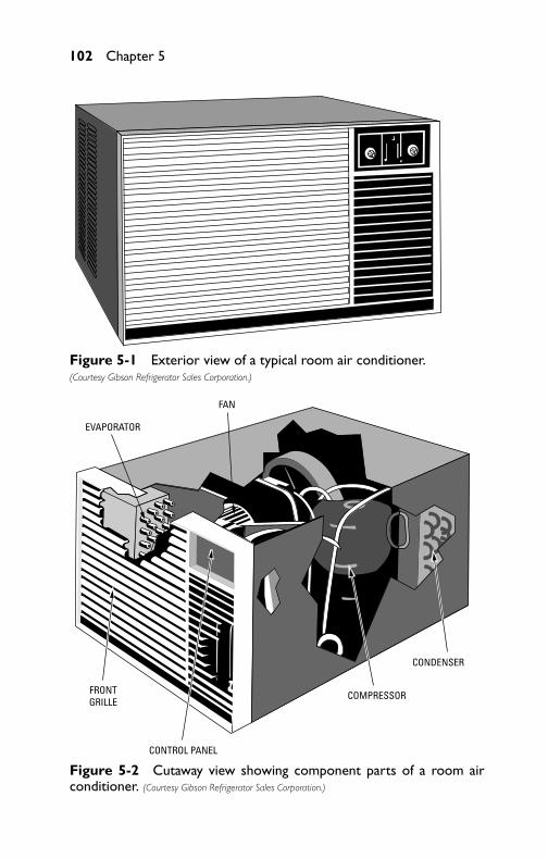
P1: GDZ/FFX P2: GDZ/FFX QC: GDZ/FFX T1: GDZ
GB076-05 GB076-Miller-Sample July 15, 2004 16:29 Char Count= 0
102 Chapter 5
Figure 5-1 Exterior view of a typical room air conditioner.(Courtesy Gibson Refrigerator Sales Corporation.)
FRONTGRILLE
CONTROL PANEL
COMPRESSOR
CONDENSER
EVAPORATOR
FAN
Figure 5-2 Cutaway view showing component parts of a room airconditioner. (Courtesy Gibson Refrigerator Sales Corporation.)

P1: GDZ/FFX P2: GDZ/FFX QC: GDZ/FFX T1: GDZ
GB076-05 GB076-Miller-Sample July 15, 2004 16:29 Char Count= 0
Room Air Conditioners 103
through the sections of the condenser coil on each side of the con-denser fan housing. The air passes through the compressor compart-ment. It is discharged through the center section of the condensercovered by the fan housing. It circulates the air, as well as disposingof the condensed water from the evaporator, which drops into thebase and flows to the condenser end of the unit.
Cooling CapacityThe cooling capacity of an air-conditioning unit is the ability to re-move heat from a room and is usually measured in Btu per hour.The higher the Btu rating, the more heat will be removed. The ca-pacity rating is usually given on the unit’s nameplate, together withother necessary information (such as voltage and wattage require-ments). It is important that the room air-conditioning units be largeenough for the room or rooms to be cooled. When dealing withlarge units, the term ton of refrigeration is most often used. A ton ofrefrigeration is equivalent to 12,000 Btu/hr. A room air conditionerrated at 10,000 Btu, for example, will supply 10/12, or 0.83, ton ofrefrigeration.
Capacity RequirementsFollowing are the important variables to keep in mind when esti-mating the Btu requirements for a room cooling installation:� Room size in square feet of floor area� Wall construction (whether light or heavy)� Heat gain through ceiling� The proportion of outside wall area that is glass� The exposure of the room’s walls to the sun
Additional factors to be taken into account are room ceilingheight, number of persons using the room, and miscellaneous heatloads (such as wattage of lamps, radio and television sets in use inthe room, and so on).
Table 5-1 should be used to obtain the approximate cooling ca-pacity in Btu. The following steps outline the procedure for usingthe table (which shows the Btu requirements for various sizes ofrooms). In each case, it is assumed that the rooms have an 8-footceiling height. The procedure is as follows:
1. Measure the room to be cooled for square footage (length infeet times width in feet).
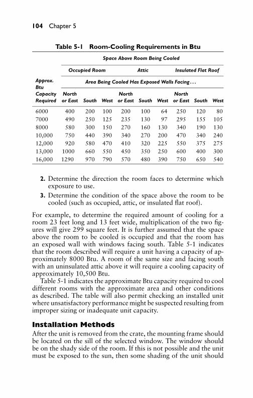
P1: GDZ/FFX P2: GDZ/FFX QC: GDZ/FFX T1: GDZ
GB076-05 GB076-Miller-Sample July 15, 2004 16:29 Char Count= 0
104 Chapter 5
Table 5-1 Room-Cooling Requirements in Btu
Space Above Room Being Cooled
Occupied Room Attic Insulated Flat Roof
Area Being Cooled Has Exposed Walls Facing . . .Approx.BtuCapacity North North NorthRequired or East South West or East South West or East South West
6000 400 200 100 200 100 64 250 120 807000 490 250 125 235 130 97 295 155 1058000 580 300 150 270 160 130 340 190 13010,000 750 440 390 340 270 200 470 340 24012,000 920 580 470 410 320 225 550 375 27513,000 1000 660 550 450 350 250 600 400 30016,000 1290 970 790 570 480 390 750 650 540
2. Determine the direction the room faces to determine whichexposure to use.
3. Determine the condition of the space above the room to becooled (such as occupied, attic, or insulated flat roof).
For example, to determine the required amount of cooling for aroom 23 feet long and 13 feet wide, multiplication of the two fig-ures will give 299 square feet. It is further assumed that the spaceabove the room to be cooled is occupied and that the room hasan exposed wall with windows facing south. Table 5-1 indicatesthat the room described will require a unit having a capacity of ap-proximately 8000 Btu. A room of the same size and facing southwith an uninsulated attic above it will require a cooling capacity ofapproximately 10,500 Btu.
Table 5-1 indicates the approximate Btu capacity required to cooldifferent rooms with the approximate area and other conditionsas described. The table will also permit checking an installed unitwhere unsatisfactory performance might be suspected resulting fromimproper sizing or inadequate unit capacity.
Installation MethodsAfter the unit is removed from the crate, the mounting frame shouldbe located on the sill of the selected window. The window shouldbe on the shady side of the room. If this is not possible and the unitmust be exposed to the sun, then some shading of the unit should

P1: GDZ/FFX P2: GDZ/FFX QC: GDZ/FFX T1: GDZ
GB076-05 GB076-Miller-Sample July 15, 2004 16:29 Char Count= 0
Room Air Conditioners 105
be used for greater efficiency. Awnings are most effective since theyshade both the unit and window at the same time, but the awningmust not restrict the free flow of air to and from the unit. The awningtop must be held away from the building side so that the hot air canescape. Venetian blinds or shades are a second choice to cut downa great amount of solar heat transmitted to the room through thewindows.
Before installing the unit, it should be determined first that it is thecorrect size for the room and that the electrical power plug is correctand adequate. Whatever type of installation is used, ensure that thelocation will permit proper distribution of the cooled air throughoutthe room (as shown in Figure 5-3) and that there is no obstructionto the outside air flow that could cause restriction or recirculation ofoutside air back into the unit. The installation instructions providedwith the unit should be studied and followed closely. The installationinformation included here is only general and not intended to replaceor substitute the instructions supplied with the unit. The installationshould be made as neat as possible. Make certain that the unit isproperly secured and that the installation is made so there is a goodtight seal from the outside. It is very important that no openings areleft through which rain or warm air from the outside could enteraround the unit.
Figure 5-3 Air circulation with an accompanying cooling effect pro-vided by a typical window-mounted air-conditioning unit.

P1: GDZ/FFX P2: GDZ/FFX QC: GDZ/FFX T1: GDZ
GB076-05 GB076-Miller-Sample July 15, 2004 16:29 Char Count= 0
106 Chapter 5
Double-Hung Window InstallationMost window units are manufactured for installation in sliding win-dows with free openings from 27 to 40 inches in width. The properinstallation of these units is very important to their continued satis-factory performance, and manufacturers’ instructions and illustra-tions should be carefully studied and adhered to. The following is astep-by-step procedure that will assist in reducing installation time:
1. The depth of the unit will determine if it is to be mountedflush to the inside finished wall or at any point between theseextremes.
2. Measure and mark the center of the windowsill with a line, asshown in Figure 5-4. Extend the line to the outside sill for usein installing the mounting-frame support. The purpose of thewindow angles is to hold the side panel in the window channel.Outside of the panel, place the window angle and adjust it forheight; outline and drill pilot holes. Screw the angle firmlyin place. Repeat the operation with the other angle on theopposite side of the window frame.
L
L/ 2
L/ 2
cL
cL
Figure 5-4 Method of measuring windowsill to establish mountingposition of an air-conditioning unit.
3. Place the mounted assembly (see Figure 5-5) in the window,aligning the center hole in the lower frame with the centerlinemark on the windowsill. Lower the window to the top of theframe. Extend sides of the mounted assembly to the full width

P1: GDZ/FFX P2: GDZ/FFX QC: GDZ/FFX T1: GDZ
GB076-05 GB076-Miller-Sample July 15, 2004 16:29 Char Count= 0
Room Air Conditioners 107
of the window, as shown by arrows. Install sash-locking brack-ets after seating the window firmly on the assembly frame.
FILLER BOARD
ALIGN
UNIT SUPPORTARRANGEMENT
(WHEN REQUIRED)
SASH-LOCKING BRACKET
Figure 5-5 Method of installing unit-support frame and filler boards.
4. Break off excess filler board by pressing outward at the near-est notch beyond the unit opening of the mounting frame, asshown in Figure 5-6. This operation is easier (especially forwider windows) if a pair of pliers is used.
5. Install the screws as shown in Figure 5-7 if permanent instal-lation is desired. Use of screws is recommended.

P1: GDZ/FFX P2: GDZ/FFX QC: GDZ/FFX T1: GDZ
GB076-05 GB076-Miller-Sample July 15, 2004 16:29 Char Count= 0
108 Chapter 5
FILLER BOARDS
cLFigure 5-6 Method of filler-board installation.
MOUNTING FRAME SUPPORT FILLER BOARD
Figure 5-7 Method of securing sill clamp to wooden windowsill.
6. Install the bottom unit seal in the groove of the frame, as shownin Figure 5-8. Stretch the seal material to fill the groove com-pletely.
7. Install the sill clamp in lieu of the sill-fastening screws for stonesills or other such materials, as shown in Figure 5-9.

P1: GDZ/FFX P2: GDZ/FFX QC: GDZ/FFX T1: GDZ
GB076-05 GB076-Miller-Sample July 15, 2004 16:29 Char Count= 0
Room Air Conditioners 109
SEALING MATERIAL
Figure 5-8 Unit seal arrangement.
TOP RAIL FILLER BOARD
MOUNTING FRAME SUPPORT SILL CLAMP
Figure 5-9 Sill-clamp mounting in stone or masonry sill construction.
8. Install the top rail and seal assembly (see Figure 5-10) on topof the unit case in the holes provided for flush mounting only.
9. Remove the unit decorative grille (see Figure 5-11) and in-stall locking screws (two) on flush-mount installations only.Reinstall the grille.

P1: GDZ/FFX P2: GDZ/FFX QC: GDZ/FFX T1: GDZ
GB076-05 GB076-Miller-Sample July 15, 2004 16:29 Char Count= 0
110 Chapter 5
TOP RAIL
UNIT SUPPORT FILLER BOARD
SILL CLAMP
Figure 5-10 Method of installing top rail and seal assembly.
TOP RAIL FILLER BOARD
SILL CLAMP
AIR-CONDITIONING UNIT
Figure 5-11 Placement of air-conditioning unit.

P1: GDZ/FFX P2: GDZ/FFX QC: GDZ/FFX T1: GDZ
GB076-05 GB076-Miller-Sample July 15, 2004 16:29 Char Count= 0
Room Air Conditioners 111
10. Install the side seals by forcing them between the unit (fillerboards and unit frame).
11. Install the sash-to-glass seal, cutting it to fit the window glasswidth, as shown in Figure 5-12.
CUT LINE
SEALING MATERIAL
TOP RAIL
AIR-CONDITIONING UNIT
FILLER BOARD
Figure 5-12 Sealing-installation arrangement.
Casement Window InstallationSo many different types of casement windows are manufactured thatit would be impossible to give a single procedure to cover them all.Each job will require special treatment, thought, and planning. With

P1: GDZ/FFX P2: GDZ/FFX QC: GDZ/FFX T1: GDZ
GB076-05 GB076-Miller-Sample July 15, 2004 16:29 Char Count= 0
112 Chapter 5
FILLER PANEL
CASEMENT WINDOW W
ITH GLASS
AND MULLIONS REMOVED
Figure 5-13 Necessary changes required to permit installation ofwindow-mounted air-conditioning unit in casement-type window.
reference to Figure 5-13, installation is accomplished by removingsufficient glass and mullions to allow for passage of the unit. Itis necessary to build up the windowsill until the top is above thehorizontal cross member forming the bottom of the frame on themetal window. If the outer cabinet is allowed to rest on this cross

P1: GDZ/FFX P2: GDZ/FFX QC: GDZ/FFX T1: GDZ
GB076-05 GB076-Miller-Sample July 15, 2004 16:29 Char Count= 0
Room Air Conditioners 113
member, any vibration will be transmitted to the window frame andwall and will be amplified. This starting procedure is basic to allcasement windows.
Measure the height and width of the opening left by the removedglass, and cut a piece of 1/4-inch Masonite or equivalent material tofit. This board is referred to as a filler panel. Cut out the center ofthe filler panel to the exact outside dimensions of the outer cabinet.In cutting the height in the board, allow for the height of the bot-tom cross member on the window frame. Install the outer cabinet,as described previously (in the section titled Double-Hung WindowInstallation). Install the filler panel in the opening, and seal the edgesto the window frame with putty or caulking compound. The hori-zontal cross member of the supporting frame may be secured to thetemporary sill by using the holes provided for this purpose, or theclamping assembly may be used if it is practical for the installation.Install chassis and the insides of the cabinet.
Alternative MethodMeasure the height of the opening. From this subtract height ofthe unit. Cut a piece of plywood, Masonite, or Plexiglas equal inheight to fit the measurement obtained as a result of the foregoingsubtraction and with a width equal to the opening. Install the outercabinet in the exact center of the opening and secure rigidly. Installthe filler board across the top of the unit. Cement these in place atthe window frame.
Casement windows with small glass panes will require the cuttingout of a horizontal cross member, as well as vertical mullions. In thiscase it may be advisable to reinstall the cross members at a heightequal to the height of the outer cabinet. Cut and reinstall the glassabove the cross members. The regular side panels supplied with theunit may be used to fill in the sides, or Plexiglas may be used.
Wall InstallationsIn certain locations, it may be desirable to cut through the existingwall and install the air conditioner in the opening thus provided.When cutting through the existing wall, carefully measure the airconditioner to be installed and cut a hole in the wall large enoughto provide for the conditioner as well as the required framing andinsulating sleeves.
Frame ConstructionFigure 5-14 illustrates a typical framing preparation. Insert the cab-inet into the opening. Screw through the cabinet into the framing,as shown. The existing knockouts can be used for either of the twopositions. Additional holes will have to be drilled along the length

P1: GDZ/FFX P2: GDZ/FFX QC: GDZ/FFX T1: GDZ
GB076-05 GB076-Miller-Sample July 15, 2004 16:29 Char Count= 0
114 Chapter 5
WOOD HEADEROR FRAMING
WOOD HEADEROR
FRAMING
WOOD SIDING
CAULK COMPLETELYAROUND UNIT
TRIMCOLLAR
ANCHORING SCREWS
6"
BRICK VENEER
9"
7"
Figure 5-14 Method of wood-header arrangement to provide supportin frame-wall installation.
of the cabinet for other positions. Also screw the bottom rails to theframing, using No. 14 screws. After assembling the cabinet securely,the wood-trim strips can be nailed around the cabinet.
Caulking and flashing should be used around the outside to pro-vide a weather-tight seal. Instead of caulking at the bottom, a panwith side flanges and a drip rail may be used to protect the wallopening. The pan should be sloped to the rear and should providea weather-tight seal.
Concrete Block or Brick ConstructionTo prepare the wall, remove all plaster, furring strips, and so onfrom the installation area. Be careful not to break the plaster orexterior wall surface beyond the hole’s dimensions. After obtain-ing the proper opening, insert the cabinet and secure it with ma-sonry nails. The existing knockouts can be used for either of the two

P1: GDZ/FFX P2: GDZ/FFX QC: GDZ/FFX T1: GDZ
GB076-05 GB076-Miller-Sample July 15, 2004 16:29 Char Count= 0
Room Air Conditioners 115
positions. Additional holes will have to be drilled along the lengthof the cabinet for other positions.
After installation, cement the cabinet to the existing masonryon the outside. Use caulking and flashing to provide a weather-tight seal. Instead of caulking at the bottom, a pan with side flangesand a drip rail may be used to protect the wall opening. The panshould be sloped to the rear and should provide a weather-tight seal.Wood-trim strips may be applied around the inside of the cabinetto complete the installation.
Outside Support BracketIf the air conditioner extends more than 14 inches beyond the outsideof the wall opening, the cabinet will require additional support fromthe outside. This support may be obtained by using the mountinglegs and brackets, and corresponding nuts, bolts, and washers assupplied with the mounting kit for the standard window installation.Make sure that the mounting brackets rest firmly against the wallat the wall opening, as shown in Figure 5-15.
Figure 5-15 Support-bracket arrangement in typical window instal-lation.
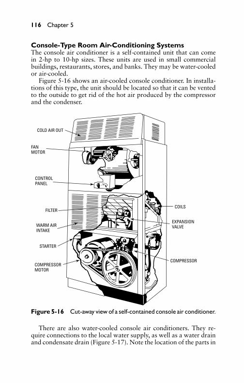
P1: GDZ/FFX P2: GDZ/FFX QC: GDZ/FFX T1: GDZ
GB076-05 GB076-Miller-Sample July 15, 2004 16:29 Char Count= 0
116 Chapter 5
Console-Type Room Air-Conditioning SystemsThe console air conditioner is a self-contained unit that can comein 2-hp to 10-hp sizes. These units are used in small commercialbuildings, restaurants, stores, and banks. They may be water-cooledor air-cooled.
Figure 5-16 shows an air-cooled console conditioner. In installa-tions of this type, the unit should be located so that it can be ventedto the outside to get rid of the hot air produced by the compressorand the condenser.
COLD AIR OUT
FANMOTOR
CONTROLPANEL
FILTER
WARM AIRINTAKE
STARTER
COMPRESSORMOTOR
COMPRESSOR
EXPANSIONVALVE
COILS
Figure 5-16 Cut-away view of a self-contained console air conditioner.
There are also water-cooled console air conditioners. They re-quire connections to the local water supply, as well as a water drainand condensate drain (Figure 5-17). Note the location of the parts in
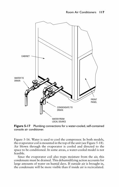
P1: GDZ/FFX P2: GDZ/FFX QC: GDZ/FFX T1: GDZ
GB076-05 GB076-Miller-Sample July 15, 2004 16:29 Char Count= 0
Room Air Conditioners 117
CABINET
WATER TODRAIN
CONDENSATE TODRAIN
WATER FROMLOCAL SOURCE
FRONTPANEL
Figure 5-17 Plumbing connections for a water-cooled, self-containedconsole air conditioner.
Figure 5-16. Water is used to cool the compressor. In both models,the evaporator coil is mounted in the top of the unit (see Figure 5-18).Air blown through the evaporator is cooled and directed to thespace to be conditioned. In some areas, a water-cooled model is notfeasible.
Since the evaporator coil also traps moisture from the air, thiscondensate must be drained. This dehumidifying action accounts forlarge amounts of water on humid days. If outside air is brought in,the condensate will be more visible than if inside air is recirculated.

P1: GDZ/FFX P2: GDZ/FFX QC: GDZ/FFX T1: GDZ
GB076-05 GB076-Miller-Sample July 15, 2004 16:29 Char Count= 0
118 Chapter 5
WARMAIRIN
BLOWER
COMPRESSOR
CONDENSER
FLOOR
COLDAIROUT
OUTSIDE WALL
EVAPORATOR
Figure 5-18 A self-contained console air conditioner, showing air flowover the evaporator.

P1: GDZ/FFX P2: GDZ/FFX QC: GDZ/FFX T1: GDZ
GB076-05 GB076-Miller-Sample July 15, 2004 16:29 Char Count= 0
Room Air Conditioners 119
Installation and ServiceThe console air conditioner is produced by the factory ready forinstallation. It must be moved to a suitable location and hookedto electrical and plumbing supplies. Once located and connected,it must be checked for level. Electrical and plumbing work mustconform to local codes.
Servicing the unit is simple because all the parts are located inone cabinet. Remove the panels to gain access to the compressor,valves, blowers, filter, evaporator, and motors. A maintenance sched-ule should be set up and followed. Most maintenance consists ofchanging filters and checking pressures. Cleaning the filters, clean-ing the inside of the cabinet with a vacuum, and cleaning the evapo-rator fins are the normal service procedures. Water connections andelectrical control devices should be checked for integrity. Clean thefan motor. Oil the bearings on the blowers and motors wheneverspecified by the manufacturers.
Window-Mounted Console-Type Air ConditionersIt is extremely desirable that a survey of the room is made prior to theactual installation of a console unit. Determine the most favorablelocation, taking into account the desirable location in the room,exposure of the window, width of the window, its height from thefloor, and location of the electrical supply outlet. In this connection,it should be realized that since these types of units usually have aconsiderably larger cooling capacity than windowsill units, it willbe necessary to install a special electrical connection from the meteror distribution panel directly to the location of the unit.
Figure 5-19 shows the installation of a typical console room airconditioner in a double-hung window. A normal installation of thistype will allow the window to be opened or closed without interfer-ence from the duct or window filler panels. To completely close thewindow, the rain hood must be retracted. To adjust the height of theunit to obtain the necessary height for the duct outlet (windowsillheight may differ by several inches), special wooden bases made upof several sections are usually employed (see Figure 5-20).
Installing DuctsThe standard duct (see Figure 5-21) usually furnished with theconsole-type unit is approximately 8 inches deep. The unit end hasa removable flange that slides on vertical tracks attached to the backof the unit. The window end of the duct has a rain hood fitted in it.When the window is up, the rain hood is pushed out manually and

P1: GDZ/FFX P2: GDZ/FFX QC: GDZ/FFX T1: GDZ
GB076-05 GB076-Miller-Sample July 15, 2004 16:29 Char Count= 0
120 Chapter 5
AIR DUCT
CONSOLE AIR- CONDITIONING UNIT
Figure 5-19 Console-type air-conditioning unit installation in standarddouble-hung window.
secured in the open position by inserting a screw in each side of theduct after the holes in the duct and rain hood are lined up.
The distance between the window and the nearest permissiblelocation of the unit is measured direct and laid out on the duct,measuring from the window end. Remove the screws holding theremovable fitting to the duct, scribe, and cut. File off all burrs andbreak the sharp edges. Use the standard duct if the dimension is 8inches or less. If the dimension is greater than 8 inches, the standardand accessory ducts can be connected together to give a total distanceof 20 inches. When cutting the accessory duct, be sure to take themeasurement from the flared end to allow the extension piece to fitover the standard section. Use the unit fitting to locate new holesin the cut end. Drill with a 1/8-inch drill and reassemble. Installation

P1: GDZ/FFX P2: GDZ/FFX QC: GDZ/FFX T1: GDZ
GB076-05 GB076-Miller-Sample July 15, 2004 16:29 Char Count= 0
Room Air Conditioners 121
WOODEN BASE5 SECTIONS.
EACH 3/4’ THICK
DOWEL-PIN HOLE
Figure 5-20 Typical wooden base assembly. Wooden base may beused to increase the height of console units to permit the standard ductto rest on windowsill.
NOTE:Duct may be cut hereto suit requirements.
UNIT FITS OVER ENDOF EITHER DUCT
ACCESSORY12-IN DUCT
STANDARD 8-IN DUCT
RAIN HOOD
Figure 5-21 Typical air-duct units as used with console-type air con-ditioners.
P1: GDZ/FFX P2: GDZ/FFX QC: GDZ/FFX T1: GDZ
GB076-05 GB076-Miller-Sample July 15, 2004 16:29 Char Count= 0
122 Chapter 5
of a console air conditioner in casement windows does not differ inany appreciable degree from installation of the windowsill-mountedtype.
Electrical SystemTo ensure that the room air-conditioning unit operates properly, youshould check the available electrical power supply before the unit isinstalled. If an existing branch circuit is to be used, you must ensurethat it is the proper rating and that the voltage is correct for the unitto be installed (120 volts or 240 volts, whichever appears on theunit nameplate). You should also ensure that the electric supply atthe outlet is adequate to maintain proper unit operation (see Figure5-22.)
The following specifications for the operation of room air-conditioning units from electric branch circuits are accepted by theNational Electrical Code and most local codes and ordinances:
� The unit nameplate amperage should not exceed 80 percent ofthe branch circuit rating. For example, a No. 14 wire circuitis rated at 15 amperes; 80 percent of 15 = 12 amperes, whichis maximum loading.� If a unit nameplate amperage is greater than 50 percent of
the circuit rating, then there should be no other outlet in thatcircuit available for additional loading by other electrical ap-pliances, lights, and so on.� If the unit amperage does not exceed 50 percent of the circuit
rating, then a multiple-outlet circuit can be used if the addi-tional loading of the circuit combined with the unit amperagedoes not exceed 80 percent of the circuit rating.
It should be noted also that the determination of a circuit’s ad-equate rating does not necessarily establish that there is adequatevoltage available for satisfactory operation of the unit. It is suggested(particularly on 120-volt circuits) that a voltage check be made withthe circuit loaded by a current draw comparable to that of the unitnameplate amperage. The voltage under this loading should notdrop lower than 10 percent below the unit nameplate voltage. If thevoltage drops too low at the outlet, but remains satisfactory at themeter, a new branch circuit is necessary.
Electrical load testers are available with selectable wattage thatpermits simulating a unit current draw. These instruments have apower cord with a wall plug that can be installed directly in theelectrical outlet used for the unit. If the voltage does not drop below

P1: GDZ/FFX P2: GDZ/FFX QC: GDZ/FFX T1: GDZ
GB076-05 GB076-Miller-Sample July 15, 2004 16:29 Char Count= 0
Room Air Conditioners 123
120 V
PARALLEL
240 V
TANDEM
240 V
CROWFOOT
120 V 20 AMP
120 V 20 AMP
120 V 20 AMP
L5-20
L5-20
5-20
G W
GW
GW
Figure 5-22 Line cords and plugs for various voltages as used on air-conditioning units.
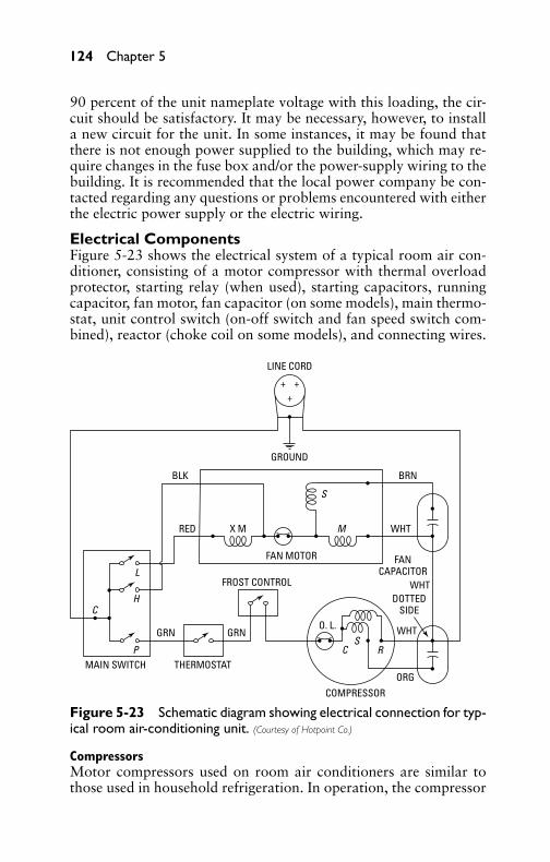
P1: GDZ/FFX P2: GDZ/FFX QC: GDZ/FFX T1: GDZ
GB076-05 GB076-Miller-Sample July 15, 2004 16:29 Char Count= 0
124 Chapter 5
90 percent of the unit nameplate voltage with this loading, the cir-cuit should be satisfactory. It may be necessary, however, to installa new circuit for the unit. In some instances, it may be found thatthere is not enough power supplied to the building, which may re-quire changes in the fuse box and/or the power-supply wiring to thebuilding. It is recommended that the local power company be con-tacted regarding any questions or problems encountered with eitherthe electric power supply or the electric wiring.
Electrical ComponentsFigure 5-23 shows the electrical system of a typical room air con-ditioner, consisting of a motor compressor with thermal overloadprotector, starting relay (when used), starting capacitors, runningcapacitor, fan motor, fan capacitor (on some models), main thermo-stat, unit control switch (on-off switch and fan speed switch com-bined), reactor (choke coil on some models), and connecting wires.
+ ++
THERMOSTATMAIN SWITCH
GRN GRN
FROST CONTROL
FAN MOTOR
COMPRESSOR
FANCAPACITOR
WHT
WHT
WHT
DOTTEDSIDE
ORG
RED
BLK BRN
GROUND
LINE CORD
X M M
S
C
L
H
P CS
R
O. L.
Figure 5-23 Schematic diagram showing electrical connection for typ-ical room air-conditioning unit. (Courtesy of Hotpoint Co.)
CompressorsMotor compressors used on room air conditioners are similar tothose used in household refrigeration. In operation, the compressor

P1: GDZ/FFX P2: GDZ/FFX QC: GDZ/FFX T1: GDZ
GB076-05 GB076-Miller-Sample July 15, 2004 16:29 Char Count= 0
Room Air Conditioners 125
action necessary for the circulation of the refrigerant is obtained bya piston reciprocating inside a cylinder similar to that of an auto-mobile engine. Half of the shaft rotation is used to draw gas into thecylinder, and the other half is used for compression and discharge.Reciprocating compressors are usually furnished in two styles: asingle cylinder (pancake type), with a speed of 3500 rpm, and atwin-cylinder type with a speed of 1750 rpm. Figure 5-24 shows theinterior and exterior views of a pancake-type compressor.
Figure 5-24 View of singlecylinder, pancake-typecompressor. (top) Exteriorview; (bottom) cutaway view.

P1: GDZ/FFX P2: GDZ/FFX QC: GDZ/FFX T1: GDZ
GB076-05 GB076-Miller-Sample July 15, 2004 16:29 Char Count= 0
126 Chapter 5
Starting RelayThe starting-relay coil is in series with the motor run winding. Thehigh current draw on start causes the relay contacts to close, connect-ing the starting capacitor to the compressor-start winding circuit. Asthe motor speed increases, current through the run winding dropsoff and the relay contacts open. This cuts out the starting capaci-tor, and the compressor continues to run with a running capacitorremaining in the start winding circuit.
Following are the most common faults of a starting relay:
� Relay contacts fail to open when the compressor has started.� Relay contacts do not close while the compressor is starting.
If the relay contacts fail to open when the compressor has started,starting capacitor failure would likely result and the compressorwould draw high amperage. If the relay contacts were not closedwhen the compressor was starting, difficulty could be encoun-tered.
Overload ProtectorThe overload protector protects the motor against excessive over-load and is usually located inside the compressor terminal cover.It opens the circuit to the compressor motor on abnormally highamperage or objectionably high motor temperature. The overloadprotector on most models consists of a snap-action, bimetal diskwith contacts. The motor current passes through this disk. In thecase of overload (failure of the compressor to start or unusual volt-age conditions), the current through the disk will be high, therebyincreasing its temperature and causing it to automatically open andstop the motor. Because of its direct contact with the compressorbody, as the motor temperature rises, the heat of the compressorbody will increase the overload disk temperature. This lessens therequired current to open the circuit.
Some models have a heater combined with the bimetal disk. Ex-cessive current through this heater causes the temperature to rise andheat the disk. When the overload protector trips for any reason, themotor circuit remains open until the compressor cools sufficientlyto cause the disk to snap closed, closing the circuit.
Starting CapacitorsAll capacitors have two ratings: a microfarad (µF) rating and a volt-age rating. The microfarad rating identifies the capacitor’s electricalcapacitance, while the voltage rating identifies the maximum volt-age. A 240-volt capacitor may be used on a 120-volt circuit, but a120-volt capacitor cannot be directly connected across 240 volts.

P1: GDZ/FFX P2: GDZ/FFX QC: GDZ/FFX T1: GDZ
GB076-05 GB076-Miller-Sample July 15, 2004 16:29 Char Count= 0
Room Air Conditioners 127
Starting capacitors are the electrolytic type and are used in themotor-start winding circuit to affect an increase in starting torque.All starting capacitors are intended for short and infrequent com-pressor starts. Any operating fault that would cause a starting ca-pacitor to remain in the circuit for more than several seconds couldbe the cause of its failure. Such causes could be low voltage, faultyrelay, some fault of the compressor, short cycling, or a compres-sor motor failure. The cause of repeated capacitor failure should beinvestigated as being one those mentioned previously.
If a starting capacitor becomes shorted internally, starting troubleand possible blown fuses would result. If a capacitor should have abroken internal connection to either terminal or any internal opencircuit to its terminals, the compressor may not start. If a replace-ment is available, the simplest way to check a capacitor is to installa new one. If the trouble is corrected, discard the old capacitor.
Run-CapacitorsRun-capacitors differ from start-capacitors in that they are heavy-duty, oil-filled capacitors that can remain in the circuit continuously.Running capacitors have a much lower microfarad (µF) rating thanstart-capacitors of comparable size. The run-capacitor remains inthe motor-start winding circuit at all times during compressor op-eration. This capacitor also increases starting torque and improvesthe motor’s running abilities. The run-capacitor also reduces therunning amperage by increasing the power factor.
Fan MotorsThere are usually two types of fan motors. Some air conditioners usea permanent split-phase capacitor motor, and others use a shaded-pole type. The capacitor type is more efficient electrically, and it isused where there are current limitations. It can be identified since itrequires a fan capacitor. The number of fan-motor leads will varyfrom two to four, depending on the type of motor used and its appli-cation. Shaded-pole motors will have either two or three leads, de-pending on whether the speed winding is incorporated in the motoror a reactor is used to reduce the fan speed. Similarly, capacitor-typemotors will either have three or four leads for the same reason.
It is very important that the fan-motor leads be connected cor-rectly to prevent damage to the motor. Reversal of the run and phaseleads will result in motor rotation reversal on capacitor-type motors.All fan motors have a thermal overload protector embedded in thewindings to protect the motor from damage in case of overheat-ing. Certain types of air conditioners employ a reactor (sometimescalled a choke coil) that is used to reduce the speed of the fan motor

P1: GDZ/FFX P2: GDZ/FFX QC: GDZ/FFX T1: GDZ
GB076-05 GB076-Miller-Sample July 15, 2004 16:29 Char Count= 0
128 Chapter 5
externally. When connected in the fan-motor circuit, the reactoradds reactance, lowering the voltage to the fan motor and therebyreducing the motor speed.
ThermostatsThe thermostat (or temperature control) stops and starts the com-pressor in response to room temperature requirements. Each ther-mostat has a charged power element containing either a volatile liq-uid or an active vapor charge. The temperature-sensitive part of thiselement (thermostat feeler bulb) is located in the return air stream.As the return air temperature rises, the pressure of the liquid orvapor inside the bulb increases, which closes the electrical contactsand starts the compressor. As the return air temperature drops, thereduced temperature of the feeler bulb causes the contacts to openand stops the compressor.
The advent of transistors and the semiconductor chips or inte-grated circuits has produced a more accurate method of monitoringand adjusting temperatures within a system. The microprocessormakes use of the semiconductor and chip’s abilities to compare tem-peratures and to program on and off cycles, as well as monitor theduration of each cycle. This leads to more accurate temperaturecontrol.
Figure 5-25 shows a microprocessor-based thermostat. As youcan see from the front of the control panel, you can adjust the
RUNPROGRAM
SETPRESENTDAY TIME
HOLDTEMP SET
HEAT COOL
DAY WAKE LEAVE
PERIOD TIME
TEMPERATURE
RETURN
HEAT OFF COOL AUTO
AHEAD WARMER
PRESENTSETTING
SKIPNEXT
PERIOD
CHANGETO LASTPERIOD
COOLERBACK
SLEEP
FAN ON AUTO
ENRO SAV SYSTEM
MON LEAVE
AM
Figure 5-25 Microprocessor thermostat used for residential temper-ature and cooling control.

P1: GDZ/FFX P2: GDZ/FFX QC: GDZ/FFX T1: GDZ
GB076-05 GB076-Miller-Sample July 15, 2004 16:29 Char Count= 0
Room Air Conditioners 129
program to do many things and, in the process, save energy, whetherit is operating the furnace for heat or the air-conditioning unit forcooling. These units usually come with a battery so that the mem-ory can retain whatever is programmed into it. The battery is also abackup for the clock so that the program is retained even if the linepower is interrupted.
Unit Control SwitchThe unit control switch may be located on top of the cabinet or onone of the sides, depending upon the particular design. The con-trol switch is usually of the knob- or rotary-control dial type andnormally has four positions, marked OFF, FAN, COOL, and EX-HAUST. The damper controls are usually marked SHUT, VENT,and OPEN. To provide cooling, the switch dial is turned to theCOOL position, and the damper dial to SHUT or VENT dependingon whether or not outside air is desired.
To operate the unit as a ventilator, the switch dial is turned to FANand the damper dial is turned as far open as desired. In the OPENposition, the unit passes in 100 percent of outside air. To exhaustroom air, the switch is turned to the EXHAUST position, and thedamper dial is turned to the VENT position. When a thermostat isinstalled for automatic cooling, the compressor and fans will cycleaccording to dial requirements.
Service OperationsRoom-air-conditioner servicing is similar to refrigerator servicing.An air conditioner is a refrigerant system that removes heat froma room. (In a refrigerator, the heat is removed from the food.) Anevaporator is employed to remove the heat, and a condenser is usedto liquefy the refrigerant. Air movement over the evaporator andcondenser surface is accomplished by a fan. Hot air usually con-tains a greater percentage of moisture than colder air. When theevaporator fan moves hot humid air over the cold surface of theevaporator, a quantity of the moisture in the air will condense (formwater droplets) in addition to the air itself being cooled. In this man-ner, the relative humidity of the recirculated air is also reduced. Thecondensate water is drained into the condenser section, where it isdissipated.
Servicemen who have a good knowledge of refrigeration com-bined with the understanding that an air conditioner removes heatand humidity from a room by the process of refrigeration will beable to competently service air conditioners. Since most portable air-conditioning units of present design contain compressors of the her-metic or sealed type, the only parts that can be serviced in the field
P1: GDZ/FFX P2: GDZ/FFX QC: GDZ/FFX T1: GDZ
GB076-05 GB076-Miller-Sample July 15, 2004 16:29 Char Count= 0
130 Chapter 5
are the relay, control switch, fan, fan motor, starting and runningcapacitors, air filters, and cabinet parts. The refrigerating system(consisting of the cooling unit, condensers, compressors, and con-necting lines) generally cannot be serviced in the field.
Dismantling Window Air ConditionersThis section lists the procedure and steps necessary to dismantlewindow air conditioners. The procedure can be used in its entiretyor in part, according to the service required. The procedure coversonly those parts of the unit that can be serviced in the field andis not a complete disassembly. By presenting a dismantling proce-dure, it is possible to eliminate repetition of certain steps common tomany service operations. Keep in mind that individual manufactur-ers may recommend a slightly different procedure. In all instances,follow the instructions of the manufacturer when dismantling anair conditioner. When reassembling the unit, the steps should bereversed.
To dismantle the air conditioner, proceed as follows:
1. Disconnect the air conditioner from the source of electric sup-ply, and remove the cabinet.
2. Remove the electric control boxes. Remove the screws thatsecure each box to the partition. Remove the control-box cov-ers, and disconnect the motor leads. Remove the control boxassemblies from the unit.
3. Remove the fan motor and fans. Loosen both fans, and removethem from the shaft. Remove the access panel that fits downover the cooling-unit fan shaft. Loosen and remove the motorcradle supports at each end of the motor. Lift the motor upand out.
Electrical TestingIn the event of operating trouble, a thorough check of the electricalsystem is sometimes necessary. By checking the electrical system, agreat deal of time can be saved because such a check usually revealsthe more obvious troubles. To make a complete electrical test ofthe unit and its controls, a volt-ohmmeter is the safest and easiestinstrument to use. It may be used to check the line voltage to see if itis high enough, and, by using the ohm-resistance scales, continuitychecks can also be performed.
When checking the electrical system, refer to the wiring diagramssuch as those shown in Figure 5-26 and Figure 5-27. However, keepin mind that the diagrams shown are only typical; the arrangement

P1: GDZ/FFX P2: GDZ/FFX QC: GDZ/FFX T1: GDZ
GB076-05 GB076-Miller-Sample July 15, 2004 16:29 Char Count= 0
Room Air Conditioners 131
RELAY
OVERLOAD
FANMOTOR
STARTING CAPACITOR
COMPRESSOR TERMINAL BOX
BLACK
BLACK
CABLE
WHITE
S
M
L1
3
C S R
N L1
2
STARTRELAY
SWITCH BOXSCREW
STARTINGWINDING
RUN WINDING
OVERLOAD
FANMOTOR
STARTINGCAPACITOR
SCHEMATIC WIRING DIAGRAM
NB
L1
L1
BS
S
WW
G
L3
1
1
23 SR
L
MR
1
Figure 5-26 Wiring diagram of typical air-conditioning unit having onefan motor and a sealed-type compressor unit.
and wiring of components may vary, depending on the manufacturerof the particular unit.
Testing for Current SupplyWith the volt-ohmmeter set on the proper AC voltage scale, firstcheck the convenience outlet that the unit is plugged into to becertain that current is available. Next, with the unit plugged intothe outlet and the volt-ohmmeter on the same setting, place one ofthe test leads on terminal N and the other on terminal L. If theproper voltage is recorded, current is being supplied to the relay.
Testing Fan MotorsDepending on the size of the unit, it may be equipped with one ortwo fan motors. In some smaller units, only one fan motor is used,in which case the shaft of the motor extends to operate two fans(one for the evaporator and one for the condenser).
To check for continuity, always pull the plug on the supply cordfrom the source of supply so as not to damage the ohmmeter portionof the instrument. To check the evaporator fan motor, turn the switch
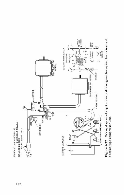
P1: GDZ/FFX P2: GDZ/FFX QC: GDZ/FFX T1: GDZ
GB076-05 GB076-Miller-Sample July 15, 2004 16:29 Char Count= 0
STAR
TRE
LAY
RELA
Y
SWIT
CHBO
XSC
REW
STAR
TIN
GW
INDI
NG
MAI
NW
INDI
NG
OVER
LOAD
OVER
LOAD
FAN
MOT
OR
EVAP
ORAT
OR
STAR
TIN
GCA
PACI
TOR
STAR
TIN
G CA
PACI
TOR
SCHE
MAT
IC W
IRIN
G DI
AGRA
M
COM
PRES
SOR
TERM
INAL
BOX
SM
L
3
2
CS
R
NB
L 1L 1
L 1
L 2L 3
B
B
SS
W
1
1
23
3
L M R
SRW
W
C
CON
DEN
SER
MOT
ORFA
N
BLK
BLK
BLK
WHT
WHT
WHT
GRN
NSW
ITCH
SWIT
CH B
OX
STAN
DARD
120
-V 2
-PRO
NG
PLUG
2-W
IRE
LEAD
-IN C
ABLE
3-W
IRE
LEAD
-IN C
ABLE
240-
V 3-
PRON
G PL
UG
CABL
E AS
SEM
BLY
CON
DEN
SER
FAN
MOT
OREVAP
ORAT
OR F
ANM
OTOR
Fig
ure
5-27
Wir
ing
diag
ram
ofa
typi
cala
ir-co
nditi
onin
gun
itha
ving
two
fan
mot
ors
and
ase
aled
-typ
eco
mpr
esso
run
it.
132
P1: GDZ/FFX P2: GDZ/FFX QC: GDZ/FFX T1: GDZ
GB076-05 GB076-Miller-Sample July 15, 2004 16:29 Char Count= 0
Room Air Conditioners 133
to the running position. Remove the connector from the wires tiedtogether in the switch box. Place the ohmmeter test leads betweenterminal 1 of the switch and the wire ends from which the connectorwas removed, which is the lead that goes to the fan motor. If the ohm-meter shows continuity, the circuit to and through the motor is okay.
Most motors are of the high-impedance type, which can stall andnot burn out, but some have internal overload protection. If themotor has overload protection and is hot, allow it to cool a fewminutes. If the ohmmeter has given an infinity reading, test again. Ifthe meter still reads infinity, replace the fan motor. If the fan motorchecks out, check the switch by putting one lead of the ohmmeteron N or L1 (they are tied together), and touch the other lead toterminal 1 and then to terminal 2. If the switch has been turned on,you should get a 0-ohm reading each time. If the switch is defective,replace it with a switch having the same part number.
To check the condenser fan motor, turn the switch to the run-ning position. If the condenser fan motor does not operate, removethe junction box cover and switch, first disconnecting the wholeunit from the power source. Remove the connector from the wirestied together. Place the ohmmeter leads on the wire that goes to thecondenser motor from the connection where you removed the con-nector, and connect the other ohmmeter lead to terminal 3 of theswitch. If the ohmmeter reads relatively low, the winding is probablyokay. If it reads 0 ohm, the winding is probably open in the motor.If the motor is hot, wait a few minutes and read again if the firstreading was 0 ohm.
To check the evaporator and condenser fan motor when onlyone fan motor is used, disconnect the whole unit from the source ofsupply. Turn the switch to the ON position, and remove the junction-box cover and switch. Remove the connector from the wires tiedtogether in the switch box. Pick out the wire that goes to the motor,and place one ohmmeter test lead on this wire end and the other leadon terminal 1. If the motor is okay, you should get a comparativelylow resistance reading. If the meter reads 0 ohm and the motor is hot,let the motor cool a few minutes and recheck. If the meter still reads0 ohm, the winding is probably open, so replace the motor. Youshould check the switch-contact continuity, as explained previously.
Capacitor (Starting)Most units have an electrolytic start-capacitor in the start-windingcircuit to increase the starting torque. If this capacitor develops ashort internally, starting trouble and possible blown fuses will result.If the capacitor develops an open circuit, the compressor will not

P1: GDZ/FFX P2: GDZ/FFX QC: GDZ/FFX T1: GDZ
GB076-05 GB076-Miller-Sample July 15, 2004 16:29 Char Count= 0
134 Chapter 5
start. If a replacement is available, the simplest way to check thecapacitor is to install a new one. If a replacement is not readilyavailable, a check can be performed in the following manner.
To check a capacitor, disconnect the capacitor leads. Ensure thatthe capacitor has not retained a charge by placing the blade of aninsulated screwdriver across the terminals. Touch the capacitor leadsor terminals with the test probes of an ohmmeter, and observe themeter deflection. A satisfactory capacitor will show at least 100,000ohm (100 K) of resistance. It may take several seconds to arrive atthis reading. A shorted capacitor causes the ohmmeter pointer toindicate a continuous low resistance. The pointer moves to the zeroend of the scale and remains there as long as the probes are in contactwith the terminals. An open capacitor causes no deflection of thepointer, meaning that there is no path or continuity through thecapacitor, which should be replaced. It is essential that the capacitorbe replaced with an exact duplicate.
Compressor Motor RelayThe relay opens the circuit to the compressor motor starting windingafter the compressor has started. The duration of this start (or ofthe time that the starting winding is energized) is, under normalconditions, very short—usually 2 or 3 seconds. A defective relay mayfail to close, which results in starting trouble. It may fail to open,which results in overload trip-outs, capacitor failure, or blown fuses.
Relay CheckCheck the capacitor before making any relay-operation checks, sincea shorted or open capacitor will not allow the motor to operate.Disconnect the entire unit from the supply source. Disconnect leadS from the relay, and check the continuity from S to L. The readingshould be 0 ohm. Replace lead S to the relay, and disconnect leadM at the relay, testing the resistance between M and L. The readingshould be 0 ohm. These tests indicate that the starting and runningcontacts of the relay are closed. To double-check, in most cases relaysmay be opened and visual inspection of the contacts made. If thecontacts show much burning or discoloration, even though they aremaking contact, replace the relay as a preventive measure.
Compressor Motor OverloadThe overload is a protective device used in conjunction with therelay to open the compressor motor circuit at abnormally high cur-rents or dangerously high motor temperatures. The overload con-sists of a heater and a snap-action bimetal disk on which contactsare mounted. A heater is connected in series with the common
P1: GDZ/FFX P2: GDZ/FFX QC: GDZ/FFX T1: GDZ
GB076-05 GB076-Miller-Sample July 15, 2004 16:29 Char Count= 0
Room Air Conditioners 135
terminal of the motor windings. In the case of overloads, the currentthrough the heater is high, thereby increasing its temperature. Thisheats the bimetal disk, thus causing it to automatically snap openand open the motor-winding circuit. Because of the direct contact ofthe overload to the compressor body, as the motor temperature rises,the heat of the compressor body increases the overload-disk temper-ature, thereby reducing the current required to open the circuit.
If the overload trips for any reason, the circuit will remain openuntil the compressor body (or shell) cools sufficiently to cause thedisk to snap closed. It will then close the circuit to the motor. Thisprotector is nonadjustable and must be replaced if it fails to functionproperly. To check the overload, disconnect the power cord fromits source, remove leads 2 and 3 from the overload, and check thecontinuity between terminals 2 and 3. The meter should read 0 ohm.If the test shows a high resistance, the points are open and the relayshould be replaced.
Often, you will not find an overload protector as shown in Fig-ure 5-28 because it is a part of the start-relay. Some of the causesof overload trip-outs are low voltage, shorted capacitor, failure ofthe compressor to start, and excessive operating pressures or tem-peratures. It is a good idea to have a clamp-on–type AC ammeter tocheck running currents.
Compressor and MotorThe compressor motor is a capacitor-type, split-phase motor thathas two windings. The starting winding has the capacitor in serieswith it to give great starting torque, with the winding composed ofa smaller-size wire than the running winding. By using a capillary-tube method of refrigeration, the starting load is normally ratherlow. At the start, the running winding is energized, drawing a largerstarting current, which causes the relay to close the starting windingcontacts, energizing the starting winding almost immediately.
As the motor comes up to speed, the current value drops. Atabout 65 percent of full speed, the current drops low enough for thestarting relay to open the circuit to the starting winding and the fullload is then carried by the running winding. If the load is too heavy,the current draw will be large and the overload protective devicewill open and stop the motor until the overload protection cools,when it will again attempt to start the motor.
To check the continuity of the compressor motor winding, dis-connect the three motor leads C, S , and R (Figure 5-28), makingsure the entire unit is unplugged from the source of electrical supply.The ohmmeter should show continuity between any two of the three

P1: GDZ/FFX P2: GDZ/FFX QC: GDZ/FFX T1: GDZ
GB076-05 GB076-Miller-Sample July 15, 2004 16:29 Char Count= 0
136 Chapter 5
terminals, with a larger resistance between terminals C and S thanbetween C and R . If the ohmmeter shows no resistance on any ofthe tests, an open winding is indicated.
While making the preceding test, you should test the compres-sor motor for grounding. This is done by putting the ohmmeter onits highest scale and touching one lead to the compressor housingand the other to each of the motor terminals, one at a time. If thewinding is not grounded, the ohmmeter should read full scale (orthe maximum resistance) in ohms.
TO: LINE
TO: LINE
OVERLOADPROTECTOR
C
M
S
S
R
11
23
NOTE: If start capacitor is installed, wire-start capacitor between terminals #1 and #2 of relay and do not use jumper wire shown.
Figure 5-28 Note location of the overload protector in line that leadsto SCR connections on the compressor. (Courtesy of Tecumseh.)

P1: GDZ/FFX P2: GDZ/FFX QC: GDZ/FFX T1: GDZ
GB076-05 GB076-Miller-Sample July 15, 2004 16:29 Char Count= 0
Room Air Conditioners 137
It must be remembered that faults other than motor trouble maybe the cause of compressor failure or of a motor drawing high cur-rent. Some of the compressor failure causes are a stuck compressor,high head pressure, low voltage, or a plugged capillary tube.
Oiling of MotorsThe fan motors should be oiled at the start of each cooling season,or every six months if the unit is operated all year. Use a good gradeof electric motor oil or SAE No. 20 automobile oil. A few drops ineach oil hole are sufficient.
Leaks in SystemIn the event that any part of the condensing unit develops a leak,it will be necessary to repair the leak before the unit can be putinto operation. A leak is usually discovered by the presence of oilaround the point at which the leak developed. It must not be as-sumed, however, that the presence of oil on any part of the unit is apositive indication of a leak. Always check the suspected area withan approved leak detector.
FiltersThe filters should be inspected at regular intervals. Refer to indi-vidual manufacturer’s instructions for filter removal and cleaning.Periodic cleaning of filters ensures maximum air delivery by the airconditioner at all times. Best results can be obtained if filters arereplaced every year and cleaned often between replacements.
Interior CleaningThe interior of the unit should be cleaned periodically of all dust,grease, and foreign matter. Special attention should be given to thecondenser and evaporator coils. Regular cleaning will ensure con-tinuous good service of the unit.
Winter CareIn many parts of the United States, service of the cooling unit willnot be required during the winter months. Such a unit can be easilyremoved from the window and stored in a convenient place. Thisprevents condensation of moisture in the unit. It also makes availablea greater window area. Before the unit is stored, however, it shouldbe checked for dirt in the evaporator and condenser, and cleanedwhen necessary. The evaporator should be cleaned once a year. Avoidthe development of objectionable odors and possible accumulationof dirt this way.

P1: GDZ/FFX P2: GDZ/FFX QC: GDZ/FFX T1: GDZ
GB076-05 GB076-Miller-Sample July 15, 2004 16:29 Char Count= 0
138 Chapter 5
The coils can be cleaned by the use of a stiff bristle brush anda strong solution of soap and water. All parts should be rinsed offafter cleaning. It is also advisable to wash out the drain pan andretouch with an asphalt paint. When storing the unit, it should beput on blocks to take the weight off the sponge rubber mounting.At the beginning of the cooling season when the unit is reinstalled,the fan motors should be oiled. After the unit has been reinstalledand started, it should be checked after a few minutes of operationto ascertain that the temperature drop across the evaporator is 10◦For more.
Refrigerant-System ServiceWhen a unit operates but does not have its normal cooling capacity,the refrigerant system should be checked. Check for some obvioussymptom (such as partial icing of the evaporator, an abnormallywarm suction line, or other unusual condition) that could indicatea loss of refrigerant or a restricted capillary tube.
The refrigerant system of most room air-conditioning units is asealed-type circuit. Should trouble develop that requires opening therefrigerant circuit, the usual caution and requirements for repair ofa capillary-tube–type system are necessary. This requires equipmentfor evacuating and leak testing, as well as a means of accurate refrig-erant charging. Observe all appropriate safety precautions specificto the refrigerant.
Evaporator TemperatureUnder average operating conditions of outdoor and indoor temper-atures, all evaporator return bends should be cold and at the sameapproximate temperature. On most models, this check can be eas-ily made by removing the front grille. If the first evaporator passesare iced over, or if there is a noticeable temperature increase of thereturn bends of the last several passes, it could be an indication ofeither restriction or loss of refrigerant. It must be remembered, how-ever, that with higher outdoor temperatures, the very last evaporatorpass will not have as much refrigerant to effect cooling as it wouldhave at lower temperatures. Therefore, it will be at a slightly highertemperature if the outside temperature is high.
Frequently, servicemen check the dry-bulb temperature dropacross the evaporator to determine if the unit is cooling satisfactorily.The temperature drop across the evaporator is not the same on allunits. Higher outdoor dry-bulb temperatures and high inside relativehumidity tend to reduce the dry-bulb temperature drop across the

P1: GDZ/FFX P2: GDZ/FFX QC: GDZ/FFX T1: GDZ
GB076-05 GB076-Miller-Sample July 15, 2004 16:29 Char Count= 0
Room Air Conditioners 139
evaporator. On most units with an outdoor temperature between80◦F and 90◦F and with an indoor relative humidity between 40and 50 percent, the temperature drop across the evaporator shouldbe between 17◦F and 20◦F. Where proper evaporator air flow ismaintained, a 20◦F dry-bulb temperature drop would normally in-dicate satisfactory cooling. When the room air relative humidity isconsiderably higher than 50 percent, a smaller dry-bulb tempera-ture drop across the evaporator will be obtained. When the relativehumidity is considerably below 40 percent, a higher temperaturewill result. It is, therefore, important that room air relative humid-ity be checked and considered when checking air temperature dropacross the evaporator as a check for proper cooling.
Compressor AmperageWith normal evaporator loading and average outdoor temperatures,if proper cooling is being accomplished, the compressor motor willdraw the approximate amperage shown on the unit nameplate. If aunit is drawing considerably below compressor nameplate amper-age, the refrigerant system may not be producing proper cooling,assuming that there is a normal flow of air over the evaporator andthat the evaporator loading is not abnormally low.
Refrigerant LeaksWhenever a shortage of refrigerant is suspected, this condition canbe confirmed by identifying the source of leakage. A leak-test oper-ation can be performed with a halide leak detector. The end of theexploring hose is passed around areas where a refrigerant leak issuspected. The air drawn into the hose passes through a copper re-actor plate and through a small flame. If any refrigerant is containedin this air, the color of the flame turns slightly green. If a consider-able quantity of refrigerant is leaking, the flame turns purple. Whenthe location of leak has been determined, it is sometimes difficult topinpoint the exact leak location. Soapsuds can be used to pinpointthe exact source of leak.
Automatic Expansion ValvesAutomatic expansion valves are used on some room air conditionersinstead of the capillary tubes to control the flow of refrigerant intothe evaporator. These valves are set to maintain a normal suctionpressure. They are factory adjusted and sealed, and no field adjust-ment is required. A small bleed port in the valve permits pressureequalization from the high to low side on shutdown. A small liquid-line strainer is located in the liquid line ahead of the expansion valve.

P1: GDZ/FFX P2: GDZ/FFX QC: GDZ/FFX T1: GDZ
GB076-05 GB076-Miller-Sample July 15, 2004 16:29 Char Count= 0
140 Chapter 5
Table 5-2 Room Air Conditioner Troubleshooting Guide
Symptom Possible Cause Possible Remedy
Unit will notrun.
Blown fuse Replace fuse.
Broken or loose wiring Check for an electricalshort at wall receptacle.
Low voltage Check voltage. Voltageshould be within 10percent of that shown onthe unit nameplate.
Defective unit startingswitch
Check voltage at switch. Ifthere is proper voltage atswitch but no continuitythrough it, replace switch.
Fan runs, butcompressorwill notoperate.
Inoperative thermostat If turning thermostat to itscoldest setting does notstart compressor (androom temperature is above75◦F) but shorting acrossits terminals does, changethermostat.
Loose or broken wiring Check unit wiring andwiring connections at theunit, start-switch andcompressor.
Start-capacitor faulty(if used)
Check start-capacitor (ifused).
Run-capacitor faulty Check run-capacitor.Relay faulty (if used) Check relay (if used).Off on overload oroverload fault
Check for overheatedcompressor or fordefective overload.
Low voltage Check voltage.
Unit blowsfuses.
Shorted or incorrectunit wiring
Check unit wiring.
Shorted start- orrun-capacitor
Check capacitors.
Shorted or stuckcompressor
Check compressor.
Compressor startingdifficulty
Check for low voltage;check start-capacitor andrelay.
Incorrect fuse Check fuse size.(continued)

P1: GDZ/FFX P2: GDZ/FFX QC: GDZ/FFX T1: GDZ
GB076-05 GB076-Miller-Sample July 15, 2004 16:29 Char Count= 0
Room Air Conditioners 141
Table 5-2 (continued)
Symptom Possible Cause Possible Remedy
Compressorcycles off andon.
Low voltage Check voltage andamperage with unitoperating. If low, checkother appliance loads.
Restricted air acrossthe condenser
Check condenser fan andcheck for any restriction ofcondenser air.
Recycling of condenserdischarge air back intounit
Check for inadequateclearance for properdischarging of condenserair; check for any cause ofhot discharge airre-entering the unit.
Dirty or pluggedcondenser
Check and clean all dirt orlint from condenser coilfins. Clean air filter.
Thermostat feeler bulbout of position
Check bulb for properlocation in return air. Bulbshould not touch theevaporator coil.
Faulty or incorrectoverload
Check if overload hastripped. Refer toCapacitor, Overload andRelay Chart for correctoverload. Checkcompressor temperatures.If compressor is notoverheated, and ifamperage is not high andoverload trips out, changeoverload.
Unit vibratesor rattles.
Compressor shippingblock not removed orshipping bolts notremoved or properlyloosened
Remove shipping bolt andshipping block onexternally spring-mountedcompressors only.
Discharge or suctiontube striking metalsurface
Bend tube slightly forclearance where striking.
Loose compressorjunction-box cover orcapacitor
Tighten.
(continued)

P1: GDZ/FFX P2: GDZ/FFX QC: GDZ/FFX T1: GDZ
GB076-05 GB076-Miller-Sample July 15, 2004 16:29 Char Count= 0
142 Chapter 5
Table 5-2 (continued)
Symptom Possible Cause Possible Remedy
Loose or bent fanblades
Replace fan.
Fan motor out ofalignment or loose onmounting
Check alignment andtighten mounting.
Water dripsfrom unit.
Unit not properlyleveled
Level unit. Most modelscan be tipped slightlytoward outside.
Condensate drain tocondenser pan plugged
Clean condensate drain.
Condenser-fan slingerring out of position
Check motor mountingand alignment for properpositioning ofcondenser-fan slinger ringin water sump.
Evaporator drip pan,shroud, or othersource of waterleaking and requiressealing
Use Permagum or othersealing compound to sealleak.
Noisy fanoperation.
Fan striking Check for properpositioning and clearanceof fans.
Loose fan or fan motor Check for fan tightness onshaft. Check for loose fanblade, fan looseness atrubber hub, and loosefan-motor mounting.
Bent fan blades Replace fan blades.
Unit notcoolingproperly.
Clogged air filter Check air filter for dirt.Clean or replace.
Outside air enteringthe unit
Check for proper closingof outside air doors.
Air across condenserrestricted
Check condenser air.
Dirty or blockedcondenser
Check condenser forblocked dirt or lint. Cleanor replace.
(continued)
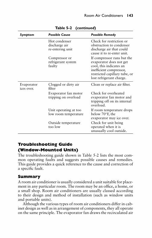
P1: GDZ/FFX P2: GDZ/FFX QC: GDZ/FFX T1: GDZ
GB076-05 GB076-Miller-Sample July 15, 2004 16:29 Char Count= 0
Room Air Conditioners 143
Table 5-2 (continued)
Symptom Possible Cause Possible Remedy
Hot condenserdischarge airre-entering unit
Check for restriction orobstruction to condenserdischarge air that couldcause it to re-enter unit.
Compressor orrefrigerant systemfaulty
If compressor runs but theevaporator does not getcool, this indicates aninefficient compressor,restricted capillary tube, orlost refrigerant charge.
Evaporatorices over.
Clogged or dirty airfilter
Clean or replace air filter.
Evaporator fan motortripping on overload
Check for overheatedevaporator fan motor andtripping off on its internaloverload.
Unit operating at toolow room temperature
If room temperature dropsbelow 70◦F, theevaporator may ice over.
Outside temperaturetoo low
Check for unit beingoperated when it isunusually cool outside.
Troubleshooting Guide(Window-Mounted Units)The troubleshooting guide shown in Table 5-2 lists the most com-mon operating faults and suggests possible causes and remedies.This guide provides a quick reference to the cause and correction ofa specific fault.
SummaryA room air conditioner is usually considered a unit suitable for place-ment in any particular room. The room may be an office, a home, ora small shop. Room air conditioners are usually classed accordingto their design and method of installation (such as window unitsand portable units).
Although the various types of room air conditioners differ in cab-inet design as well as in arrangement of components, they all operateon the same principle. The evaporator fan draws the recirculated air

P1: GDZ/FFX P2: GDZ/FFX QC: GDZ/FFX T1: GDZ
GB076-05 GB076-Miller-Sample July 15, 2004 16:29 Char Count= 0
144 Chapter 5
into the unit through the louvers located on the side. The air passesthrough the air-filter evaporator. It is then discharged through thegrill on the front of the unit into the room.
A ton of refrigeration is 12,000 Btu/hr. Room air conditioners arerated in Btu/hr. The amount of cooling capacity can be determinedby checking a table of values for various Btu ratings.
A number of installation methods may be employed in mountingair conditioners in the window of a desired room. Some units comewith filler boards to make the unit fit any size window. A console-type air-conditioning unit can be made to fit a standard double-hungwindow.
Line cords and plugs vary according to the voltage and currentthe unit will draw. At least six different standard-type plugs areavailable for window or room air conditioners.
The electrical components of a room air conditioner consist of amotor-compressor (with thermal overload protector), starting relay(when used), starting capacitor, running capacitor, fan motor, fancapacitor on some models, main thermostat, unit control switch(made up of the ON-OFF and speed selection switches).
Compressors may be of single- or double-cylinder type. Rotarycompressors are used in some units to reduce the noise inherent withthe reciprocating types.
Room air-conditioner servicing is similar to refrigerator servic-ing. An air conditioner is a refrigerant system that removes heatfrom a room, whereas a refrigerator removes the heat from the foodcompartment and from the food inside it.
When checking the electrical system, refer to the wiring diagram.Keep in mind that the compressor motor is a capacitor-type, split-phase motor that has two windings. Fan motors should be oiled atthe start of each cooling season, or every six months if the unit isoperated all year. Use a good grade of electrical oil or SAE No. 20automobile oil. A few drops in each oil hole are sufficient.
Filters should be inspected at regular intervals. Periodic cleaningof filters ensures maximum air delivery by the air conditioner at alltimes.
Before the unit is stored for the winter, it should be checked fordirt in the evaporator and condenser and cleaned when necessary.The evaporator should be cleaned once a year, as recommended.This prevents the development of objectionable odors and possibleaccumulation of dirt. The coils should be cleaned by the use of astiff bristle brush and a strong solution of soap and water. All partsshould be rinsed off after cleaning.

P1: GDZ/FFX P2: GDZ/FFX QC: GDZ/FFX T1: GDZ
GB076-05 GB076-Miller-Sample July 15, 2004 16:29 Char Count= 0
Room Air Conditioners 145
A trouble-shooting guide should be consulted to check the symp-toms and possible causes of trouble along with the possible remedy.
Review Questions1. Where can a room air conditioner be most useful?2. List at least six parts of a room air conditioner.3. List five important variables to keep in mind when estimating
the Btu requirements for a room-cooling installation.4. What affect does a west-facing wall have on a room when
figuring the room cooling requirements in Btus?5. Why are filler boards sometimes needed in an air-conditioner
installation?6. How does the console type air conditioner differ from that of
the window type?7. What are the three specifications that the National Electrical
Code states for operation of room air-conditioning units?8. Draw the plug arrangement for a crowfoot 240-volt plug.9. What is the symbol used in the schematic diagram of a typical
air-conditioning unit for representing the compressor motor?10. Where is the start-relay located in the electrical circuit of a
room air conditioner?11. In what circuit is the overload protector located?12. What is the difference between a run-capacitor and a start-
capacitor?13. Name two types of fan motors.14. What is another name for a choke coil?15. What is the difference between an air conditioner and a refrig-
erator?16. How do you test fan motors for proper operation?17. What does CSR stand for on a compressor motor housing?18. How often should fan motors be oiled?19. What is one indication of a refrigerant leak in an air-
conditioner system?20. What happens to the color of a flame when this method is used
to detect a refrigerant leak?

P1: GDZ/FFX P2: GDZ/FFX QC: GDZ/FFX T1: GDZ
GB076-05 GB076-Miller-Sample July 15, 2004 16:29 Char Count= 0
146
P1: GDZ/FFX P2: GDZ/FFX QC: GDZ/FFX T1: GDZ
GB076-06 GB076-Miller-Sample July 15, 2004 2:39 Char Count= 0
Chapter 6RefrigerantsRefrigeration is a process of removing heat from a substance ora space. A desirable refrigerant should possess chemical, physical,and thermodynamic properties that permit its efficient applicationin refrigerating systems. In addition, there should be no danger tohealth or property in case of its escape because of leaks or otherproblems in a refrigerating system.
Desirable PropertiesThe following are requirements of a good refrigerant for commercialuse:� Low boiling point� Safe and nontoxic� Easy to liquefy at moderate pressure and temperature� High latent heat value� Operation on a positive pressure� Not affected by moisture� Mixes well with oil
In the past, refrigerants were selected for use principally for theirboiling points, pressures, and stability within the system or unit,regardless of other important necessary properties (such as non-flammability and nontoxicity). Other factors must be taken intoaccount when selecting a chemical compound for use as a refrig-erant, including molecular weight, density, compression ratio, heatvalue, temperature of compression, compressor displacement, anddesign or type of compressor, to mention only a few of the majorconsiderations.
Chlorofluorocarbon Compounds (CFCs)Chlorofluorocarbon compounds (CFCs) are organic compoundsmade of carbon, fluorine, chlorine, and hydrogen. CFCs were man-ufactured under the trade name Freon. They were developed dur-ing the 1930s. After World War II these halogenated hydrocarbons,mostly trichlorofluoromethane (CFC-11, or F-11) and dichlorodi-fluoromethane (CFC-12, or F-12), were used as aerosol-spray pro-pellants, refrigerants, solvents, and foam-blowing agents. They wereideal for these and refrigeration use because they were nontoxic and
147

P1: GDZ/FFX P2: GDZ/FFX QC: GDZ/FFX T1: GDZ
GB076-06 GB076-Miller-Sample July 15, 2004 2:39 Char Count= 0
148 Chapter 6
nonflammable. They also have the added advantage of being readilyconverted from a liquid to a gas and from a gas to a liquid.
Growing concern over stratospheric ozone depletion and its dan-gers caused a ban to be imposed on the use of CFCs in aerosol-spraydispensers in the late 1970s. This ban was by the United States,Canada, and the Scandinavian countries. By 1990, 93 nations agreedto end production of ozone-depleting chemicals by the end of thecentury. In 1992, most of those same countries agreed to end theirproduction of CFCs by 1996.
ClassificationsFor all practical purposes, the refrigerants listed in Table 6-1 areno longer used, but it is possible that you will run across them inolder installations. The refrigerants still encountered in old equip-ment are: Freon-12, Freon-22, Freon-502, and ammonia (NH3).Some information will be given on the others (for purposes of in-formation only). Table 6-2 provides pressures and temperatures forthe commonly used refrigerants.
Table 6-1 Characteristics of Typical Refrigerants
Heat of VaporizationBoiling at Boiling Point,
Name∗ point, ◦F Btu/lb (at 1 atm)
Sulfur dioxide (SO2) 14.0 172.3Methyl chloride (CH3Cl)∗ −10.6 177.80Ethyl chloride (C2H5Cl) 55.6 177.00Ammonia (NH3) −28.0 554.70Carbon dioxide (CO2) −110.5 116.00Freezol (isobutane) [(CH3)3CH] 10.0 173.50Freon-11 (CCl3F)∗ 74.8 78.31Freon-12 (CCl2F)∗ −21.7 71.04Freon-13 (CClF3)∗ −114.6 63.85Freon-21 (CHCl2F)∗ 48.0 104.15Freon-22 (CHClF2)∗ −41.4 100.45Freon-113 (CCl2F CClF2)∗ 117.6 63.12Freon-114 (CClF2)∗ 38.4 58.53Freon-115 (CClF2CF3)∗ −37.7 54.20Freon-502 −50.1 76.46
∗Note: The Freon family of refrigerants, originally designated as Freon-12,Freon-13, etc., are presently listed under various tradenames, such as Ucon-12,Ucon-22, or simply Refrigerant-12, Refrigerant-22, sometimes abbreviated R-12,R-22, R-113, etc., depending on the particular refrigerant characteristics desired.
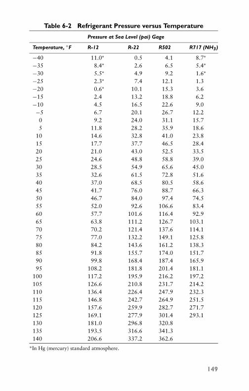
P1: GDZ/FFX P2: GDZ/FFX QC: GDZ/FFX T1: GDZ
GB076-06 GB076-Miller-Sample July 15, 2004 2:39 Char Count= 0
Table 6-2 Refrigerant Pressure versus Temperature
Pressure at Sea Level (pai) Gage
Temperature, ◦F R-12 R-22 R502 R717 (NH3)
−40 11.0∗ 0.5 4.1 8.7∗
−35 8.4∗ 2.6 6.5 5.4∗
−30 5.5∗ 4.9 9.2 1.6∗
−25 2.3∗ 7.4 12.1 1.3−20 0.6∗ 10.1 15.3 3.6−15 2.4 13.2 18.8 6.2−10 4.5 16.5 22.6 9.0−5 6.7 20.1 26.7 12.20 9.2 24.0 31.1 15.75 11.8 28.2 35.9 18.6
10 14.6 32.8 41.0 23.815 17.7 37.7 46.5 28.420 21.0 43.0 52.5 33.525 24.6 48.8 58.8 39.030 28.5 54.9 65.6 45.035 32.6 61.5 72.8 51.640 37.0 68.5 80.5 58.645 41.7 76.0 88.7 66.350 46.7 84.0 97.4 74.555 52.0 92.6 106.6 83.460 57.7 101.6 116.4 92.965 63.8 111.2 126.7 103.170 70.2 121.4 137.6 114.175 77.0 132.2 149.1 125.880 84.2 143.6 161.2 138.385 91.8 155.7 174.0 151.790 99.8 168.4 187.4 165.995 108.2 181.8 201.4 181.1
100 117.2 195.9 216.2 197.2105 126.6 210.8 231.7 214.2110 136.4 226.4 247.9 232.3115 146.8 242.7 264.9 251.5120 157.6 259.9 282.7 271.7125 169.1 277.9 301.4 293.1130 181.0 296.8 320.8135 193.5 316.6 341.3140 206.6 337.2 362.6
*In Hg (mercury) standard atmosphere.
149
P1: GDZ/FFX P2: GDZ/FFX QC: GDZ/FFX T1: GDZ
GB076-06 GB076-Miller-Sample July 15, 2004 2:39 Char Count= 0
150 Chapter 6
Refrigerants may be divided into three classes according to theirmanner of absorption or extraction of heat from the substances tobe refrigerated:� Class 1—This class includes refrigerants that cool by the ab-
sorption or extraction of latent heat from the substances tobe refrigerated. These refrigerants and their characteristics arelisted in Table 6-1.� Class 2—These refrigerants cool substances by absorbing their
sensible heats. They are air, calcium chloride brine, sodiumchloride (salt) brine, alcohol, and similar nonfreezing solu-tions. The purpose of Class 2 refrigerants is to receive a reduc-tion of temperature from Class 1 refrigerants and convey thislower temperature to the area to be air conditioned. By doingthis, a lesser amount of Class 1 refrigerant is required (whichis more expensive than Class 2 refrigerant). The results are thesame, and less of the system is subject to the problems thataccompany Class 1 refrigerant.� Class 3—This group consists of solutions that contain ab-
sorbed vapors of liquefiable agents or refrigerating media.These solutions function by nature of their ability to carry liq-uefiable vapors, which produce a cooling effect by the absorp-tion of their latent heat. Examples are ammonia and lithiumbromide, with water as the absorbing agent. (See Chapter 13for a discussion of absorption-type air conditioning.)
Class 1 refrigerants are employed in the standard compressor typeof refrigeration systems. Class 2 refrigerants are used in conjunctionwith Class 1 refrigeration, in some cases. Class 3 refrigerants areused with Class 2 systems in the same manner as Class 1 systems.
Early Types of RefrigerantsMany of the early refrigerants have distinct properties. These refrig-erants include the following:� Sulfur dioxide� Methyl chloride� Ethyl chloride� Ammonia� Carbon dioxide� Freezol (isobutane)� Calcium chloride

P1: GDZ/FFX P2: GDZ/FFX QC: GDZ/FFX T1: GDZ
GB076-06 GB076-Miller-Sample July 15, 2004 2:39 Char Count= 0
Refrigerants 151
Sulfur DioxideSulfur dioxide (SO2) is a colorless gas or liquid that is toxic and hasa very pungent odor. It is obtained by burning sulfur in air. It is notconsidered a safe refrigerant, especially in quantities. It combineswith water, forms sulfurous, and sulfuric acid, which is corrosive tometal and has an adverse effect on almost anything that it meets.It boils at about 14◦F (standard conditions) and has a latent heatvalue of 166 Btu/lb.
Sulfur dioxide has the disadvantage that it operates on a vacuumto give temperatures required in most refrigeration work. Shoulda leak occur, moisture-laden air would be drawn into the system,which eventually corrodes the metal parts and causes the compressorto stick up or stop. Also, in relation to Freon or methyl chloride,approximately one-third more vapor must be pumped to get thesame amount of refrigeration. This means that either the condensingunit will have to be sped up to give the desired capacity, or the sizeof the cylinders will have to be increased proportionately. Sulfurdioxide does not mix well with oil. The suction line must be on asteady slant to the machine; otherwise, the oil will trap out, makinga constriction in the suction line. On many installations, it is notpossible to avoid traps and, on these jobs, sulfur dioxide is notsatisfactory.
Because of its characteristic pungent odor, comparatively smallleaks are readily detected. Even the smallest leaks are readily locatedby means of an ammonia swab. A small piece of cloth or sponge maybe secured to a wire, dipped into strong aqua ammonia or householdammonia, and then passed over points where leaks are suspected.A dense white smoke forms where the sulfur dioxide and ammoniafumes come in contact. Where no ammonia is available, leaks maybe located by the usual soap bubble or oil test.
Methyl ChlorideMethyl chloride is a good refrigerant. However, because it will burnunder some conditions and is slightly toxic, it does not conform tosome city codes. Roughly speaking, the average relative concentra-tion by weight of refrigerant vapor in a room of a given size thatproduces an undesirable effect on a person breathing the air thuscontaminated may be specified approximately as follows:� Carbon dioxide—100� Methyl chloride—70� Ammonia—2� Sulfur dioxide—1

P1: GDZ/FFX P2: GDZ/FFX QC: GDZ/FFX T1: GDZ
GB076-06 GB076-Miller-Sample July 15, 2004 2:39 Char Count= 0
152 Chapter 6
In other words, methyl chloride is 35 times safer than ammoniaand 70 times safer than sulfur dioxide. To produce any serious effectsfrom breathing methyl chloride, a considerable quantity is required.For example, in a room 20 × 20 × 10 feet, it is necessary to liberateabout 60 lb of methyl chloride to produce a dangerous condition.
Methyl chloride has a low boiling point. Under standard atmo-spheric pressure, it boils at −10.6◦F. It is easy to liquefy and has acomparative high latent-heat value of approximately 178 Btu/lb un-der standard conditions. It will operate on a positive pressure as lowas −10◦F and mixes well with oil. In its dry state, it has no corrosiveeffect on metal. However, in the presence of moisture, copper plat-ing of the compressor parts results and (in severe cases of moisture)a sticky black sludge is formed, which is detrimental to the workingparts of the system.
Leaks are readily detected by means of a special leak-detectinghalide torch. Some torches use alcohol as a fuel, normally producinga colorless flame that turns green when the leak-detector tube picksup very minute concentrations of methyl chloride, and brilliant bluewith stronger concentrations. The space where the torch is beingused should be well ventilated to prevent possible harmful effects ofcombustion products. Since the pressure in all parts of the system isabove atmospheric (except in low-temperature applications), a soap-bubble or oil test also effectively locates leaks. Methyl chloride isnot irritating, and, consequently, does not serve as its own warningagent for leaks to anywhere near the degree that sulfur dioxide does.In some cases, a warning agent is added, such as a small percentage(1 percent) of acrolein.
Ethyl ChlorideBecause of the low pressure at which it evaporates, ethyl chlorideis not commonly used in domestic units. In many respects, ethylchloride is quite similar to methyl chloride. It has a boiling pointof 55.6◦F at atmospheric pressure, with a critical temperature of360.5◦F at a pressure of 784 lb absolute. Ethyl chloride is a colorlessliquid or gas with a pungent ether-like odor and sweetish taste. Itis neutral toward all metals, which allows the use of iron, copper,and even tin and lead in the construction of the unit. Since ethylchloride softens all rubber compounds or gasket material, it is bestto employ only lead as gasketing.
For the lower temperatures required for the preservation of food-stuffs, ethyl chloride must be evaporated at pressures below atmo-spheric. This is somewhat of a disadvantage because it is quite dif-ficult to detect leaks in the low or evaporating side. Large leaks willallow air or brine to be filtered or sucked into the system. On the

P1: GDZ/FFX P2: GDZ/FFX QC: GDZ/FFX T1: GDZ
GB076-06 GB076-Miller-Sample July 15, 2004 2:39 Char Count= 0
Refrigerants 153
other hand, the low pressure similarly encountered on the high orcondensing side (ranging from 6 to 20 psig) has resulted in the useof rotary compressors. Since the displacement required per unit ofrefrigeration in the compressor cylinder is excessively large, the ro-tary method of compression serves to keep down the size of the unititself, whereas a reciprocating compressor usually presents a ratherbulky appearance. Rotary compressors operate with less noise anddo not have the pounding found in the reciprocating type, espe-cially in starting up where liquid refrigerant may enter the suctionline.
Like methyl chloride, ethyl chloride presents the same difficultiesof lubrication and leak detection, with the added disadvantages ofoperating under low pressures and the detection of leaks, and a smallquantity of some liquid having a powerful or penetrating odor issometimes added to the system. The most common method of leakdetection, however, is to put pressure on the system and apply asoapy solution on the suspected points. In locations where there isno danger of explosion, a halide torch may be used. The flame willturn green when held under the leak if ethyl chloride is present.
AmmoniaAmmonia is used in absorption types of refrigeration equipment,which are operated by heat instead of by electric motors. It is a col-orless gas with a pungent characteristic odor. Its boiling temperatureat normal atmospheric pressure is −28◦F, and its freezing point is−107.86◦F. It is very soluble in water, 1 volume of water absorbing1.148 volumes of ammonia at 32◦F. It is combustible or explosivewhen mixed with air in certain proportions (about 1 volume ofammonia to 2 volumes of air) and much more so when mixed withoxygen. Because of its high latent-heat value (555 Btu at 18◦F), largerefrigeration effects are possible with relatively small-sized machin-ery. It is very toxic and requires heavy steel fittings. Pressures of 125to 200 psi are not unusual with this refrigerant. Water-cooled unitsare essential.
There are two common methods for the detection of smallammonia leaks. One is the employment of a sulfur candle, whichwill give off a very thick, white smoke if it contacts escaping am-monia. The other method is to test with phenolphthalein paper. Thefaintest trace of ammonia vapor will cause the moistened paper stripto turn pink, while a large amount of continued exposure will turn ita vivid scarlet color. Phenolphthalein paper usually may be securedfrom ammonia producers. Both of the preceding tests are convenientand accurate. Ammonia is also labeled R-717, while water is labeledR-718.

P1: GDZ/FFX P2: GDZ/FFX QC: GDZ/FFX T1: GDZ
GB076-06 GB076-Miller-Sample July 15, 2004 2:39 Char Count= 0
154 Chapter 6
Carbon DioxideCarbon dioxide is a colorless gas at ordinary temperatures, with aslightly pungent odor and acid taste. It is harmless to breathe exceptin extremely large concentrations when the lack of oxygen will causesuffocation. It is nonexplosive, nonflammable, and does not supportcombustion. The boiling point of carbon dioxide is so extremely lowthat at 5◦F, a pressure of well over 300 psi is required to preventits evaporation. At a condenser temperature of 80◦F, a pressure ofapproximately 1000 psi is required to solidify the gas. Its criticaltemperature is 87.8◦F, and its triple point is −69.9◦F.
Because of its high operating pressure, the compressor of a carbondioxide refrigeration unit is very small even for a comparativelylarge refrigerating capacity. However, because of its low efficiency(compared with other common refrigerants), it is seldom used inhousehold units. However, it is used in some industrial applicationsand aboard ships.
Leakage of carbon dioxide gas can be detected by making surethat there is pressure on the part to be tested. Then, use a soapsolution at the suspected points. Leakage into the condenser watercan be tested with the use of bromothymol blue. Both the waterentering and leaving the condenser should be tested at the same timebecause of the sensitivity of the test. When carbon dioxide is present,the normal blue color of the water containing the test chemicals willchange to yellow.
Freezol (Isobutane)Freezol is a colorless gas with a characteristic natural-gas odor. It isstable and does not react with water. It does not decompose to formforeign gases in refrigerating systems and has no corrosive actionon metals. Freezol has a boiling point of 10◦F, which permits theproduction of the desired temperature at atmospheric pressure witha positive back-pressure. Its condensing pressure is approximately49 lb gage at 90◦F. When used as a refrigerant, any good gradeof refrigerating oil may be employed as a lubricant in the system.The gas has a specific volume of 6.3 ft3/lb at 60◦F and at normalatmospheric pressure. For the detection of leaks, put pressure on thesystem and apply a soapy solution to the suspected points.
Calcium Chloride (CaCl2)Calcium chloride brine is used extensively in commercial plants asa simple carrying medium for refrigeration. In the indirect systemof refrigeration, some refrigeration medium, such as brine, is cooleddown by the direct expansion of the refrigerant and is then pumped

P1: GDZ/FFX P2: GDZ/FFX QC: GDZ/FFX T1: GDZ
GB076-06 GB076-Miller-Sample July 15, 2004 2:39 Char Count= 0
Refrigerants 155
through the material or space to be cooled, where it absorbs its sen-sible heat. Brine systems are used to advantage in large installationswhere there is danger because of leakage of the large amount of re-frigerant present and where the temperature fluctuates in the spaceto be refrigerated.
For small refrigerated rooms or spaces where it is desired to op-erate the refrigerating machine only part of each day, the brine coilsare supplemented by holdover or congealing tanks. A holdover tankis a steel tank containing strong brine in which direct expansion coilsare immersed. During the period of operation of the refrigerationmachine, the brine is cooled down. During the shutdown period,the refrigerant is capable of absorbing heat, the amount depend-ing on the quantity of brine, its specific heat, and the temperaturehead.
Congealing tanks serve the same general purpose, but operate ona different principle. Instead of storing brine, they contain a com-paratively weak brine solution that freezes or congeals to a slushymass of crystals during the period of operation. This mass of con-gealed brine, in addition to its sensible heat, is capable of absorbingheat equivalent to its latent heat of fusion. For the same refrigeratingeffect, congealing tanks can be made much smaller than holdovertanks because advantage is taken of the latent heat of fusion ofthe brine. This results in a considerable saving in construction andmaintenance costs.
In modern refrigeration plants, however, the tendency is to op-erate with brine at low temperature, which permits the use of lessbrine, less piping or smaller-diameter pipe, smaller pumps, and lowerpumping cost. In other words, instead of cooling a large volumeof brine to a given temperature, the same number of refrigerationunits is utilized in cooling a smaller volume of brine to a lowertemperature. This practice results in greater economy of installationand operation. The use of an extremely low freezing brine (such ascan be obtained with calcium chloride) is particularly desirable inthe case of shell-type coolers. Unexpected low temperatures some-times may occur in the tubes of such a cooler, either through excessvacuum on the cold side of the refrigerating unit, or from shuttingdown a brine agitator, or both. Salt brine with a minimum possi-ble freezing point of −6◦F may solidify under such conditions andcause considerable trouble and loss of operating time. In some caseswhere this has occurred, the cooler has been ruined completely.
With the exception of ammonia and brine, the refrigerants justdiscussed will seldom be found in the field today. They are the earlyrefrigerants used before the Freons.

P1: GDZ/FFX P2: GDZ/FFX QC: GDZ/FFX T1: GDZ
GB076-06 GB076-Miller-Sample July 15, 2004 2:39 Char Count= 0
156 Chapter 6
Freon RefrigerantsThe Freon family of refrigerants has been one of the major fac-tors responsible for the impressive growth of not only the homerefrigeration and air-conditioning industry, but also the commercialrefrigeration industry. The safe properties of these products havepermitted their use under conditions where flammable or more toxicrefrigerants would be hazardous.
ClassificationsFollowing are common Freon refrigerants:
� Freon-11—Freon-11 has a boiling point of 74.8◦F and haswide usage as a refrigerant in indirect industrial and commer-cial air-conditioning systems employing single or multistagecentrifugal compressors with capacities of 100 tons and above.Freon-11 is also employed as brine for low-temperature ap-plications. It provides relatively low operating pressures withmoderate displacement requirements.� Freon-12—The boiling point of Freon-12 is −21.7◦F. It is the
most widely known and used of the Freon refrigerants. It isused principally in household and commercial refrigerationand air-conditioning units, for refrigerators, frozen-food cab-inets, ice cream cabinets, food-locker plants, water coolers,room and window air-conditioning units, and similar equip-ment. It is generally used in reciprocating compressors, rang-ing in size from fractional to 800 hp. Rotary compressors areuseful in small units. The use of centrifugal compressors withFreon-12 for large air-conditioning and process-cooling appli-cations is increasing.� Freon-13—The boiling point of Freon-13 is −144.6◦F. It is
used in low-temperature specialty applications employing re-ciprocating compressors and generally in cascade with Freon-12 or Freon-22.� Freon-21—Freon-21 has a boiling point of 48◦F. It is used
in fractional-horsepower household refrigerating systems anddrinking-water coolers employing rotary vane-type compres-sors. Freon-21 is also used in comfort-cooling air-conditioningsystems of the absorption type where dimethyl ether ortetraethylene glycol is used as the absorbent.� Freon-22—The boiling point of Freon-22 is −41.4◦F. It is used
in all types of household and commercial refrigeration andair-conditioning applications with reciprocating compressors.

P1: GDZ/FFX P2: GDZ/FFX QC: GDZ/FFX T1: GDZ
GB076-06 GB076-Miller-Sample July 15, 2004 2:39 Char Count= 0
Refrigerants 157
The outstanding thermodynamic properties of Freon-22 per-mit the use of smaller equipment than is possible with simi-lar refrigerants, making it especially suitable where size is aproblem.� Freon-113—The boiling point of Freon-113 is 117.6◦F. It
is used in commercial and industrial air-conditioning and pro-cess water and brine cooling with centrifugal compression. Itis especially useful in small-tonnage applications.� Freon-114—The boiling point of Freon-114 is 38.4◦F. It
is used as a refrigerant in fractional-horsepower householdrefrigerating systems and drinking-water coolers employingrotary vane-type compressors. It is also used in indirect in-dustrial and commercial air-conditioning systems and in in-dustrial process water and brine cooling to −70◦F employingmultistage centrifugal-type compressors in cascade of 100 tonsrefrigerating capacity and larger.� Freon-115—The boiling point of Freon-115 is −37.7◦F. It is
especially stable, offering a particularly low discharge temper-ature in reciprocating compressors. Its capacity exceeds thatof Freon-12 by as much as 50 percent in low-temperaturesystems. Its potential applications include household refrig-erators and automobile air conditioning.� Freon-502—Freon-502 is an azeotropic mixture composed of
48.8 percent Freon-22 and 51.2 percent Freon-115 by weight.It boils at −50.1◦F. Because it permits achieving the capac-ity of Freon-22 with discharge temperatures comparable toFreon-12, it is finding new reciprocating compressor applica-tions in low-temperature display cabinets and in storing andfreezing of food.
Properties of FreonsThe Freon refrigerants are colorless and almost odorless, and theirboiling points vary over a wide range of temperatures. Those Freonrefrigerants that are produced are nontoxic, noncorrosive, nonirri-tating, and nonflammable under all conditions of usage. They aregenerally prepared by replacing chlorine or hydrogen with fluorine.Chemically, Freon refrigerants are inert and thermally stable up totemperatures far beyond conditions found in actual operation. How-ever, Freon is harmful when allowed to escape into the atmosphere.It can deplete the ozone layer around Earth and cause more harmfulultraviolet rays to reach the surface of the Earth.

P1: GDZ/FFX P2: GDZ/FFX QC: GDZ/FFX T1: GDZ
GB076-06 GB076-Miller-Sample July 15, 2004 2:39 Char Count= 0
158 Chapter 6
Physical PropertiesThe pressures required to liquefy the refrigerant vapor affect the de-sign of the system. The refrigerating effect and specific volume of therefrigerant vapor determine the compressor displacement. The heatof vaporization and specific volume of the liquid refrigerant affectthe quantity of refrigerant to be circulated through the pressure-regulating valve or other system device.
FlammabilityFreon is nonflammable and noncombustible under conditions whereappreciable quantities contact flame or hot metal surfaces. It requiresan open flame at 1382◦F to decompose the vapor. Even at this tem-perature, only the vapor decomposes to form hydrogen chlorideand hydrogen fluoride, which are irritating but are readily dissolvedin water. Air mixtures are not capable of burning and contain noelements that will support combustion. For this reason, Freon isconsidered nonflammable.
Amount of Liquid Refrigerant CirculatedIt should be noted that the Freon refrigerants have relatively lowheat values, but this must not be considered a disadvantage. It sim-ply means that a greater volume of liquid must be circulated perunit of time to produce the desired amount of refrigeration. It doesnot concern the amount of refrigerant in the system. Actually, it isa decided advantage (especially in the smaller- or low-tonnage sys-tems) to have a refrigerant with low heat values. This is because thelarger quantity of liquid refrigerant to be metered through the liquid-regulating device will permit the use of more accurate and more pos-itive operating and regulating mechanisms of less sensitive and lesscritical adjustments. Table 6-3 lists the quantities of liquid refriger-ant metered or circulated per minute under standard ton conditions.
Volume (Piston) DisplacementFor reason of compactness, cost of equipment, reduction of fric-tion, and compressor speed, the volume of gas that must be com-pressed per unit of time for a given refrigerating effect, in general,should be as low as possible. Freon-12 has a relatively low volumedisplacement, which makes it suitable for use in reciprocating com-pressors, ranging from the smallest size to those of up to 800-toncapacity, including compressors for household and commercial re-frigeration. Freon-12 also permits the construction of compact ro-tary compressors in the commercial sizes. Generally, low-volumedisplacement (high-pressure) refrigerants are used in reciprocatingcompressors; high-volume displacement (low-pressure) refrigerants

P1: GDZ/FFX P2: GDZ/FFX QC: GDZ/FFX T1: GDZ
GB076-06 GB076-Miller-Sample July 15, 2004 2:39 Char Count= 0
Refrigerants 159
Table 6-3 Quantities of Refrigerant Circulated per MinuteUnder Standard Ton Conditions
Pounds ln3 Liquid SpecificExpanded Ft3/lb Liquid Expanded Gravity Liquid
Refrigerant per Minute 86◦F per Minute 86◦F (Water-1)
Carbon dioxide 3.528 0.0267 162.8 0.602Freon-22 2.887 0.01367 67.97 1.177Ammonia 0.4215 0.02691 19.6 0.598Freon-12 3.916 0.0124 83.9 1.297Methyl chloride 1.331 0.01778 40.89 0.898Sulfur dioxide 1.414 0.01184 28.9 1.358Freon-114 4.64 0.01112 89.16 1.443Freon-21 2.237 0.01183 45.73 1.360Freon-11 2.961 0.01094 55.976 1.468Methylene chloride 1.492 0.01198 30.88 1.340Freon-113 3.726 0.01031 66.48 1.555
Cu in. liquid refrig./min = 200 Btu/minBtu refrig. effect/lb
× vol. liquid/lb 86◦F × 1728
are used in large-tonnage centrifugal compressors; intermediate-volume (intermediate-pressure) refrigerants are used in rotary com-pressors. There is no standard rule governing this usage.
Condensing PressureCondensing (high-side) pressure should be low to allow construc-tion of lightweight equipment, which affects power consumption,compactness, and installation. High pressure increases the tendencytoward leakage on the low side as well as the high side when pressureis built up during idle periods. In addition, pressure is very importantfrom the standpoint of toxicity and fire hazard.
In general, a low-volume displacement accompanies a high-condensing pressure, and a compromise must usually be drawnbetween the two in selecting a refrigerant. Freon-12 presents a bal-ance between volume displacement and condensing pressure. Extra-heavy construction is not required for this type of refrigerant, and sothere is little or nothing to be gained from the standpoint of weightof equipment in using a lower-pressure refrigerant.
Evaporating PressureEvaporating (low-side) pressures above atmospheric are desirableto avoid leakage of moisture-laden air into the refrigerating systemsand permit easier detection of leaks. This is especially important
P1: GDZ/FFX P2: GDZ/FFX QC: GDZ/FFX T1: GDZ
GB076-06 GB076-Miller-Sample July 15, 2004 2:39 Char Count= 0
160 Chapter 6
with open-type units. Air in the system will increase the head pres-sures, resulting in inefficient operations, and may adversely affectthe lubricant. Moisture in the system will cause corrosion and, inaddition, may freeze out and stop operation of the equipment.
In general, the higher the evaporating pressure, the higher thecondensing pressure under a given set of temperatures. Therefore,to keep head pressures at a minimum and still have positive low-side pressures, the refrigerant selected should have a boiling pointat atmospheric pressure as close as possible to the lowest tempera-ture to be produced under ordinary operating conditions. Freon-12,with a boiling point of −21.7◦F, is close to ideal in this respect formost refrigeration applications. A still lower boiling point is of someadvantage only when lower operating temperatures are required.
Pressure-Temperature ChartFigure 6-1 shows a logarithmic-scaled chart giving the relation be-tween pressure and corresponding temperatures in degrees Fahren-heit for common refrigerants. The axis of the abscissa shows thetemperature, and the axis of the ordinate shows the pressure inpounds per square inch gage and absolute, respectively.
Thus, to ascertain the pressure of a refrigerant at any particu-lar temperature, follow the desired temperature until the curve ofthat particular refrigerant is reached. The corresponding pressureis found on the pressure axis. For example, the temperature corre-sponding to a pressure of 25 psi for sulfur dioxide is approximately60◦F, and the corresponding temperature at the same pressure fordichlorodifluoromethane (Freon-12) is approximately 27.2◦F.
Refrigerant CharacteristicsThe freezing point of a refrigerant should be below any temperaturethat might be encountered in the system. The freezing point of all re-frigerants, except water (32◦F) and carbon dioxide (−69.9◦F, triplepoint), are far below the temperatures that might be encountered intheir use. Freon-12 has a freezing point of −247◦F.
Critical TemperatureThe critical temperature of a refrigerant is the highest temperature atwhich it can be condensed to a liquid, regardless of a higher pressure.It should be above the highest condensing temperature that mightbe encountered. With air-cooled condensers, in general, this wouldbe above 130◦F. Loss of efficiency caused by superheating of therefrigerant vapor on compression and by throttling expansion ofthe liquid is greater when the critical temperature is low.

P1: GDZ/FFX P2: GDZ/FFX QC: GDZ/FFX T1: GDZ
GB076-06 GB076-Miller-Sample July 15, 2004 2:39 Char Count= 0
Refrigerants 161
57
1012
1518
2021
2223
2627 2425
TRICHLOROETHYLENE - C2 HCL3
DICHLOROETHYLENE - C2 H
2 CL2
TRICHLOROTRIFLUOROETHYLENE - C2 CL3 F3
DICHLOROTETRAFLUOROETHANE - C2 CL2 F4
METHYLENE CHLORIDE - CH
2 CL2
ETHYL CHLORIDE - C2 H
5 CL
METHYL FORM
ATE - C2 H
4 O2
DICHLORODIFLUOROMETHANE - CCL2 F2
METHYL CHLORIDE - CH
3 CL ISOBUTANE - C4 H10
SULFUR DIOXIDE - SO2
TRICHLOROMONOFLUOROM
ETHANE - CCL3 F
DICHLOROMONOFLUOROM
ETHANE - CH CL2 F
SO2
AMM
ONIA - NH3
C4 H
10 C2 H
2 CL2
C2 CL3 F3
CARBON DIOXIDE - CO2
ETHANE - C2 H6
885785685585485385285
185
85756555453525151050
1000
500400300
20050403020
1009 1087654321
14.7
Pressure - Lb / In2 Abs
-60
-50
-40
-30
-20
-10
10
20
30
40
50
60
70
8090
100110
120130140150160170180190200210
0
Pressure - Lb / In2 Gage
Temperature - °F
Figure 6-1 Vapor pressure of common refrigerants at various tem-perature ranges.
All common refrigerants have satisfactorily high critical temper-atures, except carbon dioxide (87.8◦F) and ethane (89.8◦F).
These two refrigerants require condensers cooled to temperaturesbelow their respective critical temperatures, thus generally requiringwater.

P1: GDZ/FFX P2: GDZ/FFX QC: GDZ/FFX T1: GDZ
GB076-06 GB076-Miller-Sample July 15, 2004 2:39 Char Count= 0
162 Chapter 6
Hydrofluorocarbons (HFCs)There are some hydrofluorocarbon refrigerants (such as R-134a)that are made to eliminate the problems with refrigerants in the at-mosphere caused by leaks in systems. The R-134a is a nonozone-depleting refrigerant used in vehicle air-conditioning systems.DuPont’s brand name is Suva, and the product is produced in a plantlocated in Corpus Christi, Texas, as well in Chiba, Japan. Accord-ing to DuPont’s Web site, R-134a was globally adopted by all vehi-cle manufacturers in the early 1990s as a replacement for CFC-12.The transition to R-134a was completed by the mid-1990s formost major automobile manufacturers. Today, there are more than300 million cars with air conditioners using the newer refrigerant.
Latent Heat of EvaporationA refrigerant should have a high latent heat of evaporation per unitof weight so that the amount of refrigerant circulated to producea given refrigeration effect may be small. Latent heat is importantwhen considering its relationship to the volume of liquid requiredto be circulated. The net result is the refrigerating effect. Since otherfactors enter into the determination of these, they are discussedseparately.
The refrigerant effect per pound of refrigerant under standardton conditions determines the amount of refrigerant to be evapo-rated per minute. The refrigerating effect per pound is the differencein Btu content of the saturated vapor leaving the evaporator (5◦F)and the liquid refrigerant just before passing through the regulatingvalve (86◦F). While the Btu refrigerating effect per pound directlydetermines the number of pounds of refrigerant to be evaporatedin a given length of time to produce the required results, it is muchmore important to consider the volume of the refrigerant vaporrequired rather than the weight of the liquid refrigerant. By consid-ering the volume of refrigerant necessary to produce standard tonconditions, it is possible to make a comparison between Freon-12and other refrigerants so as to provide for the reproportioning of theliquid orifice sizes in the regulating valves, sizes of liquid refrigerantlines, and so on.
A refrigerant must not be judged only by its refrigerating effectper pound, but the volume per pound of the liquid refrigerant mustalso be taken into account to arrive at the volume of refrigerant tobe vaporized. Although Freon-12 has relatively low refrigerating ef-fect, this is not a disadvantage, because it merely indicates that moreliquid refrigerant must be circulated to produce the desired amountof refrigeration. Actually, it is a decided advantage to circulate large

P1: GDZ/FFX P2: GDZ/FFX QC: GDZ/FFX T1: GDZ
GB076-06 GB076-Miller-Sample July 15, 2004 2:39 Char Count= 0
Refrigerants 163
quantities of liquid refrigerant because the greater volumes requiredwill permit the use of less sensitive operating and regulating mech-anisms with less critical adjustment.
Refrigerants with high Btu refrigerating effects are not alwaysdesirable, especially for household and small commercial installa-tions, because of the small amount of liquid refrigerant in the sys-tem and the difficulty encountered in accurately controlling its flowthrough the regulating valve. For household and small commercialsystems, the adjustment of the regulating-valve orifice is most criticalfor refrigerants with high Btu values.
Specific HeatA low specific heat of the liquid is desirable in a refrigerant. If the ra-tio of the latent heat to the specific heat of a liquid is low, a relativelyhigh proportion of the latent heat may be used in lowering the tem-perature of the liquid from the condenser temperature to the evapo-rator temperature. This results in a small net refrigerating effect perpound of refrigerant circulated and, assuming other factors remainthe same, reduces the capacity and lowers the efficiency. When theratio is low, it is advantageous to precool the liquid before evapora-tion by heat interchange with the cool gases leaving the evaporator.
In the common type of refrigerating systems, expansion of thehigh-pressure liquid to a lower-pressure, lower-temperature vaporand liquid takes place through a throttling device such as an expan-sion valve. In this process, energy available from the expansion isnot recovered as useful work. Since it performs no external work, itreduces the net refrigerating effect.
Power ConsumptionIn a perfect system operating between 5 and −86◦F conditions,5.74 Btu is the maximum refrigeration obtainable per Btu of en-ergy used to operate the refrigerating system. This is the theoreticalmaximum coefficient of performance on cycles of maximum effi-ciency (for example, the Carnot cycle). The minimum horsepowerwould be 0.821 hp/ton of refrigeration. The theoretical coefficientof performance would be the same for all refrigerants if they couldbe used on cycles of maximum efficiency.
However, because of engineering limitations, refrigerants are usedon cycles with a theoretical maximum coefficient of performance ofless than 5.74. The cycle most commonly used differs in its basicform from (1) the Carnot cycle, as already explained in employingexpansion without loss or gain of heat from an outside source, and(2) in compressing adiabatically (compression without gaining or

P1: GDZ/FFX P2: GDZ/FFX QC: GDZ/FFX T1: GDZ
GB076-06 GB076-Miller-Sample July 15, 2004 2:39 Char Count= 0
164 Chapter 6
losing heat to an outside source) until the gas is superheated abovethe condensing medium temperature. These two factors, both ofwhich increase the power requirement, vary in importance with dif-ferent refrigerants. But, it so happens that when expansion loss ishigh, compression loss is generally low, and vice versa. All com-mon refrigerants (except carbon dioxide and water) show about thesame overall theoretical power requirement on a 5 to −86◦F cycle.At least the theoretical differences are so small that other factors aremore important in determining the actual differences in efficiency.
The amount of work required to produce a given refrigerat-ing effect increases as the temperature level to which the heat ispumped from the cold body is increased. Therefore, on a 5 to −86◦Fcycle, when gas is superheated above 86◦F temperature on compres-sion, efficiency is decreased and the power requirement increasedunless the refrigerating effect caused by superheating is salvagedthrough the proper use of a heat interchanger.
Volume of Liquid CirculatedVolumes of liquid required to circulate for a given refrigerant effectshould be low. This is to avoid fluid-flow (pressure-drop) problemsand to keep down the size of the required refrigerant change. Insmall-capacity machines, the volume of liquid circulated should notbe so low as to present difficult problems in accurately controllingits flow through expansion valves or other types of liquid meteringdevices.
With a given net refrigerating effect per pound, a high density ofliquid is preferable to a low volume. However, a high density tendsto increase the volume circulated by lowering the net refrigeratingeffect. See Table 6-1 for the volumes of liquid that are required tobe circulated for the various refrigerants.
Simple Refrigeration SystemThe principle of using the latent heat of vaporization of a liquid(such as sulfur dioxide) for producing refrigeration can be illus-trated very easily by thinking of a refrigerator of very simple design,similar to the one shown in Figure 6-2. The refrigerator is made upof a box that is completely insulated on all six sides to prevent asmuch heat transfer by conduction, convection, and radiation as pos-sible. A series of finned coils with one end connected to the cylindercharged with sulfur dioxide is located in the top of the cabinet. Twopounds of sulfur dioxide are charged into the coil, after which thecompressed cylinder is sealed and disconnected from the line, withthe charging end of the pipe open to the atmosphere.

P1: GDZ/FFX P2: GDZ/FFX QC: GDZ/FFX T1: GDZ
GB076-06 GB076-Miller-Sample July 15, 2004 2:39 Char Count= 0
Refrigerants 165
FINNED COIL
REFRIGERATOR
PIPE
VALVE
COM
PRES
SED
SULF
UR D
IOXI
DE G
AS (S
0 2)
LIQUID SULFURDIOXIDE (S02)
Figure 6-2 Typical refrigeration cycle.
Since the liquid sulfur dioxide is exposed to the air, the onlypressure to which the liquid is subjected is atmospheric pressure,which is approximately 14.7 psi absolute pressure, or 0 psig. Atthis pressure, the liquid sulfur dioxide will boil or vaporize at anytemperature higher than 14◦F. For example, if the temperature of theroom in which the refrigerator is located is 70◦F, the temperatureof the cabinet at the time the sulfur dioxide liquid is added willalso be 70◦F. The liquid sulfur dioxide in the coils, therefore, willstart boiling and vaporizing immediately because the surroundingtemperature is above the boiling point (14◦F) of the liquid. As theliquid boils away, it will absorb heat from the cabinet because forevery pound of sulfur dioxide liquid vaporized, 168 Btu of heat willbe extracted from the cabinet. As soon as the temperature of thecooling coil is reduced to a point lower than the cabinet temperature,the air in the cabinet will start circulating in the direction shown bythe arrows in Figure 6-2 because heat will always flow from thewarmer to the colder object.
With this method, however, the 2 lb of sulfur dioxide liquid willsoon vaporize and the colorless gas will be given off to the air outside

P1: GDZ/FFX P2: GDZ/FFX QC: GDZ/FFX T1: GDZ
GB076-06 GB076-Miller-Sample July 15, 2004 2:39 Char Count= 0
166 Chapter 6
the cabinet. It has a sharp odor. Refrigeration will then stop until anew charge is placed in the cooling coil. Sulfur dioxide is expensiveand difficult to handle, and so some means must be used to reclaimthe vapor in order to use the original charge continuously and in-definitely. The inconvenience of recharging the coil must also beprevented, and the refrigerator must be built so that it will auto-matically maintain the proper food preservation temperatures at alltimes, with absolutely no inconvenience to the customer. This is ac-complished by the compressor pulling the warm sulfur dioxide gasfrom the cooling unit and pumping it into the condenser, where it ischanged to a liquid, ready to return to the cooling unit.
Handling RefrigerantsAs mentioned at the beginning of this chapter, one of the require-ments of an ideal refrigerant is that it must be nontoxic. In reality,however, all gases (with the exception of pure air) are more or lesstoxic or asphyxiating. It is therefore important that wherever gasesor highly volatile liquids are used, adequate ventilation be provided,because even nontoxic gases in air produce a suffocating effect.
Vaporized refrigerants (especially ammonia and sulfur dioxide)bring about irritation and congestion of the lungs and bronchialorgans, accompanied by violent coughing, vomiting, and, whenbreathed in sufficient quantity, suffocation. It is of the utmost im-portance, therefore, that the serviceman subjected to a refrigerantgas find access to fresh air at frequent intervals to clear his lungs.When engaged in the repair of ammonia and sulfur dioxide ma-chines, approved gas masks and goggles should be used. Carrene,Freon (F-12), and carbon dioxide fumes are not irritating and canbe inhaled in considerable concentrations for short periods withoutserious consequences.
It should be remembered that liquid refrigerant would refrigerateor remove heat from anything it meets when released from a con-tainer. In the case of contact with refrigerant, the affected or injuredarea should be treated as if it has been frozen or frostbitten.
Storing and Handling Refrigerant CylindersRefrigerant cylinders should be stored in a dry, sheltered, and well-ventilated area. The cylinders should be placed in a horizontal po-sition, if possible, and held by blocks or saddles to prevent rolling.It is of the utmost importance to handle refrigerant cylinders withcare and to observe the following precautions:� Never drop the cylinders, or permit them to strike each other
violently.
P1: GDZ/FFX P2: GDZ/FFX QC: GDZ/FFX T1: GDZ
GB076-06 GB076-Miller-Sample July 15, 2004 2:39 Char Count= 0
Refrigerants 167
� Never use a lifting magnet or a sling (rope or chain) whenhandling cylinders. A crane may be used when a safe cradle orplatform is provided to hold the cylinders.� Caps provided for valve protection should be kept on the
cylinders at all times except when the cylinders are actuallyin use.� Never overfill the cylinders. Whenever refrigerant is discharged
from or into a cylinder, weigh the cylinder and record theweight of the refrigerant remaining in it.� Never mix gases in a cylinder.� Never use cylinders for rollers, supports, or for any purpose
other than to carry gas.� Never tamper with the safety devices in valves or on the
cylinders.� Open the cylinder valves slowly. Never use wrenches or tools
except those provided or approved by the gas manufacturer.� Make sure that the threads on regulators or other unions are
the same as those on the cylinder valve outlets. Never force aconnection that does not fit.� Regulators and gages provided for use with one gas must not
be used on cylinders containing a different gas.� Never attempt to repair or alter the cylinders or valves.� Never store the cylinders near highly flammable substances
(such as oil, gasoline, or waste).� Cylinders should not be exposed to continuous dampness, salt
water, or salt spray.� Store full and empty cylinders apart to avoid confusion.� Protect the cylinders from any object that will produce a cut
or other abrasion on the surface of the metal.
Cylinder CapacityTo determine the allowable capacity of any cylinder or other autho-rized container, first find the weight of water it will hold by weighingit full of water and subtracting the container weight. This water ca-pacity in pounds multiplied by 1.25 will give its allowable shippingcapacity for sulfur dioxide. The water capacity multiplied by 0.75will give its allowable shipping capacity for methyl chloride. Thus,for example, a cylinder weighs 120 lb empty and 243 lb when com-pletely filled with water. Its water capacity is therefore 243–120, or

P1: GDZ/FFX P2: GDZ/FFX QC: GDZ/FFX T1: GDZ
GB076-06 GB076-Miller-Sample July 15, 2004 2:39 Char Count= 0
168 Chapter 6
123 lb. It will hold 1.25 × 123, or 154, lb of sulfur dioxide, and0.75 × 123, or 92, lb of methyl chloride.
First AidThe following procedures are recommended for persons sufferingfrom exposure to refrigerants.
Ammonia FumesTake the patient into fresh air and call a physician promptly. If thepatient is unconscious, apply artificial respiration. Ammonia gas islighter than air. Keep the head as low as possible in the presenceof ammonia. Keep near the floor in going to the rescue of anyoneovercome by ammonia, and keep a wet sponge or cloth over themouth and nostrils.
Sulfur DioxideLiquid sulfur dioxide on any part of the body produces freezingthat should be treated as any ordinary frostbite. Freezing any partof the body constricts the blood vessels in that area. The naturalrestoration of circulation will hold in check unnecessary swellingand destruction of the tissues.
Every eye freezing should immediately have the service of an eyespecialist to determine the presence of ulcers and to prevent laterinfection. Do not rub the affected eye.
Methyl ChlorideExcessive exposure to methyl chloride develops the characteristicsymptoms of drowsiness, mental confusion, nausea, and possiblevomiting. In any instance of excess exposure, the patient should beremoved immediately to fresh air, and a physician should be called.Like other refrigerant gases, methyl chloride vaporizes rapidly whenit escapes, and any person who contacts liquid methyl chloridewould be subject to a freezing action. The treatment is the sameas for any freeze and is of relatively minor importance except whenthe eyes are the affected part.
In case of an accident involving the eyes, the person should betaken to an eye specialist as soon as possible.
FreonsShould the liquid gas of Freons contact the skin, the injury should betreated in the same manner as though the skin had been frostbittenor frozen. An eye injury should be treated the same as that describedfor methyl chloride. It is best to wear gloves when handling Freoncylinders. The eyes should be protected by goggles.

P1: GDZ/FFX P2: GDZ/FFX QC: GDZ/FFX T1: GDZ
GB076-06 GB076-Miller-Sample July 15, 2004 2:39 Char Count= 0
Refrigerants 169
SummaryRefrigeration, regardless of the means by which it is obtained, maybe defined as a process of removing heat from a substance or fromspace. Refrigerants, being the prime source without which mechan-ical refrigeration systems would not be possible, have been fullydescribed in this chapter.
Refrigerants are generally divided into three classes accordingto their manner of absorption or extraction of heat from the sub-stance to be refrigerated. Refrigerants are selected principally fortheir boiling points, pressures, and stability within the system. Thisincludes molecular weight, density, compression ratio, heat value,temperature of compression, and compressor displacement.
The Freon family of refrigerants has been one of the major fac-tors responsible for the large growth in the refrigeration and air-conditioning field. This is largely because the properties of Freonpermit their use under conditions where flammable or more toxicrefrigerants would be hazardous to use. Freon has been determinedto harm the environment. As a response to this threat to both theatmosphere and living organisms on Earth, newer refrigerants havebeen developed. One of the new refrigerants is referred to as R-134a,made by DuPont. It is a hydrofluorocarbon compound (HFC).
Review Questions1. Name the desirable properties of a good refrigerant for com-
mercial use.2. How are commercial refrigerants classified?3. What is the purpose of calcium chloride brine as used in com-
mercial refrigeration plants?4. Why is ammonia employed in preference to other refrigerants
in commercial plants?5. State the boiling point and heat of vaporization at the boiling
point for Freon-12.6. In what respect does the Freon family of refrigerants differ
from such refrigerants as methyl or ethyl chloride?7. Name the chemical and physical properties of Freons.8. Why is Freon-12 preferred in both commercial and household
refrigeration units, but banned by most of the world?9. What is meant by the critical temperature of a refrigerant?
10. Why does a high latent heat of evaporation per unit of weightaffect the desirability of a refrigerant?
P1: GDZ/FFX P2: GDZ/FFX QC: GDZ/FFX T1: GDZ
GB076-06 GB076-Miller-Sample July 15, 2004 2:39 Char Count= 0
170 Chapter 6
11. Describe the methods of leak detection in a refrigerationsystem.
12. What precautions should be observed in the storage and han-dling of refrigerant cylinders?
13. Enumerate the procedures recommended when suffering fromexposure to various refrigerants.
14. Why were hydrofluorocarbon refrigerants developed?15. What is the name of the new refrigerant used in automobile
air-conditioning systems?

P1: GDZ/FFX P2: GDZ/FFX QC: GDZ/FFX T1: GDZ
GB076-07 GB076-Miller-Sample July 14, 2004 22:27 Char Count= 0
Chapter 7Compressors for AirConditionersThe components necessary for operating a gas-compression refrig-eration system may be divided into two parts: mechanical and elec-trical. The mechanical components are the compressor, condenser,receiver, evaporator, and various types of refrigerant controls. In ad-dition, suitable pipelines with the necessary shutoff valves, strain-ers, driers, heat interchangers, fans, pumps, and so on are required,depending on the size of the system and other factors. The elec-trical components consist of such items as the compressor motor,compressor contactor or relay, compressor starter, overload protec-tor, capacitor, potential relay, pressure switch, transformers (whenused), evaporator fan, condenser fan, evaporator-fan relay, thermo-stat, and so on, as shown in Figure 7-1.
Mechanical ComponentsThe most common mechanical components for air conditioners con-sist of the following:
� Compressors� Condensers� Receivers� Evaporators� Refrigerant controls� Expansion valves
CompressorsCompressors are manufactured in various sizes (depending on re-quirements) and are classified according to their method of opera-tion as reciprocating, rotary, and centrifugal. The function of anycompressor is to provide the necessary pumping action to removethe refrigerant gas from the evaporator, compress the gas, and fi-nally discharge the gas into the condenser, where it is liquefied. Thepumping action of the compressor provides the means of lifting thegas from the condition of low to that of high pressure, and the vol-ume of gas to be compressed is dependent on the compressor pistondisplacement. The compressor and component parts are shown inFigure 7-2.
171

P1: GDZ/FFX P2: GDZ/FFX QC: GDZ/FFX T1: GDZ
GB076-07 GB076-Miller-Sample July 14, 2004 22:27 Char Count= 0
172 Chapter 7
RU
N
MOTOR PROTECTORWHITE
BLACKBL
ACK
BLACK TR.
RED
R
C
S
RT3
RED TR.
RED
RED
RED
START
B B
TERMINALBOX
CONNECTORT BLOCK
TO CONTROLLERYELLOW
YELLOW
YELLOW
YELL
OWBL
UE
JUNCTIONBOX
POTENTIALRELAY
STARTCAPACITOR
CAP. & RELAY ASS'Y
RUNCAPACITORS
CT1 ST2
21
5
Figure 7-1 Diagram for a compressor with a single-phase capacitor-start motor using a potential relay and motor-overload protector.(Courtesy Copeland Refrigeration Corporation.)
DISCHARGE LINE
BLOWER
BLOWER
CAPILLARY
EVAPORATOR
BULB
SUCTION LINE
MOTORCOMPRESSOR
HIGH-PRESSURE SIDELOW-PRESSURE SIDE
CONDENSER
RECEIVER
EXPANSIVEVALVE
LIQUID LINE
Figure 7-2 Typical compression-refrigeration system.
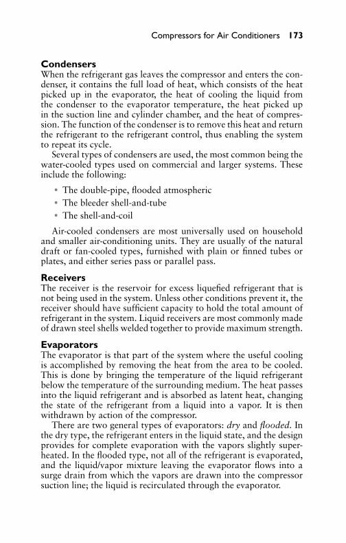
P1: GDZ/FFX P2: GDZ/FFX QC: GDZ/FFX T1: GDZ
GB076-07 GB076-Miller-Sample July 14, 2004 22:27 Char Count= 0
Compressors for Air Conditioners 173
CondensersWhen the refrigerant gas leaves the compressor and enters the con-denser, it contains the full load of heat, which consists of the heatpicked up in the evaporator, the heat of cooling the liquid fromthe condenser to the evaporator temperature, the heat picked upin the suction line and cylinder chamber, and the heat of compres-sion. The function of the condenser is to remove this heat and returnthe refrigerant to the refrigerant control, thus enabling the systemto repeat its cycle.
Several types of condensers are used, the most common being thewater-cooled types used on commercial and larger systems. Theseinclude the following:� The double-pipe, flooded atmospheric� The bleeder shell-and-tube� The shell-and-coil
Air-cooled condensers are most universally used on householdand smaller air-conditioning units. They are usually of the naturaldraft or fan-cooled types, furnished with plain or finned tubes orplates, and either series pass or parallel pass.
ReceiversThe receiver is the reservoir for excess liquefied refrigerant that isnot being used in the system. Unless other conditions prevent it, thereceiver should have sufficient capacity to hold the total amount ofrefrigerant in the system. Liquid receivers are most commonly madeof drawn steel shells welded together to provide maximum strength.
EvaporatorsThe evaporator is that part of the system where the useful coolingis accomplished by removing the heat from the area to be cooled.This is done by bringing the temperature of the liquid refrigerantbelow the temperature of the surrounding medium. The heat passesinto the liquid refrigerant and is absorbed as latent heat, changingthe state of the refrigerant from a liquid into a vapor. It is thenwithdrawn by action of the compressor.
There are two general types of evaporators: dry and flooded. Inthe dry type, the refrigerant enters in the liquid state, and the designprovides for complete evaporation with the vapors slightly super-heated. In the flooded type, not all of the refrigerant is evaporated,and the liquid/vapor mixture leaving the evaporator flows into asurge drain from which the vapors are drawn into the compressorsuction line; the liquid is recirculated through the evaporator.
P1: GDZ/FFX P2: GDZ/FFX QC: GDZ/FFX T1: GDZ
GB076-07 GB076-Miller-Sample July 14, 2004 22:27 Char Count= 0
174 Chapter 7
Refrigerant ControlsIn addition to the compressor, condenser, receiver, and evapora-tor, several auxiliaries are required for proper operation of an air-conditioning system. Certain devices must be furnished for the con-trolled expansion of the refrigerant from the high condenser pressureto the low evaporator pressure. Controls are also necessary for theon-off operation of the compressor, flow of the condensing medium,and safety purposes. Proper piping is required for interconnectionof the various parts of the system.
Expansion ValvesTo control the rate of flow of the liquefied refrigerant between thehigh- and low-side pressures of the system, some form of expan-sion device must be provided. This device is usually an expansionvalve. Automatic expansion valves are pressure-controlled devicesthat operate to maintain a constant pressure in the evaporator. Suchan expansion valve is usually applied to evaporators of the direct-expansion type, but it is not satisfactory for fluctuating loads suchas those encountered in air-conditioning installations.
Thermostatic expansion valves are similar in construction to au-tomatic expansion valves but, in addition, incorporate a power ele-ment responsive to changes in the degree of superheat of the refrig-erant gas leaving the evaporator coil. This power element consistsof a bellows connected by means of a capillary tube to a feeler bulbfastened to the suction line from the evaporator. (For further detailsof air-conditioning components, see Chapters 5, 8 to 11, and 13.)
Refrigeration CycleIn the great majority of air-conditioning applications (and almostexclusively in the smaller-horsepower range), the vapor-compressionsystem is used. In larger applications, however, absorption systemsand steam-jet vacuum systems are frequently used. The centrifugalsystem, which is largely an adaptation of the vapor-compressioncycle, is used in large-capacity industrial applications.
The vapor-compression refrigeration cycle consists of a series ofchanges of state needed to restore the refrigerant to a condition inwhich it will possess the ability to extract heat from the space to becooled. For all vapor-compression–type systems, the cycle consistsof the following four processes:
1. Heat gain in the evaporator (the vaporizing process).2. Pressure rise in the compressor (the compressing process).

P1: GDZ/FFX P2: GDZ/FFX QC: GDZ/FFX T1: GDZ
GB076-07 GB076-Miller-Sample July 14, 2004 22:27 Char Count= 0
Compressors for Air Conditioners 175
3. Heat loss in the condenser (the condensing process).4. Pressure loss in the expansion valve (the pressure-reducing
process).
Briefly, and with reference to Figure 7-2, the cycle of operationthat is the cooling process consists of four separate steps as follows:
1. Vaporizing Process—As the low-temperature, low-pressure re-frigerant in the evaporator absorbs the heat from the materialand space that is being refrigerated, it is transformed from aliquid to a vapor.
2. Compression Process—The compressor draws the heat-ladenvapor from the evaporator through the return piping. It thencompresses this vapor until the temperature is above that ofthe condensing medium.
3. Condensing Process—When the compressor has raised thetemperature of the vapor to a temperature above that of thecondensing medium (usually 15◦F to 25◦F), the heat of vapor-ization will flow from the vapor to the condensing medium andcondense the refrigerant to a high-pressure liquid. This high-pressure liquid then flows to the receiver, where it is storeduntil it is supplied to the cooling unit through the expansionvalve.
4. Pressure-Reducing Process—As the compressor withdraws therefrigerant vapor from the evaporator, the cooling unit mustbe supplied with more low-temperature, low-pressure refrig-erant capable of absorbing heat. This is accomplished by aliquid control valve known as an expansion valve. This valvehas the following functions: It reduces the pressure of the high-pressure vapor from the receiver to a low-pressure liquid capa-ble of absorbing heat; it maintains a constant supply of liquidin the evaporator; and it acts as a dividing point between thehigh- and low-pressure sides of the system.
RefrigerantsBy definition, a refrigerant is a substance that produces a refrigera-tion effect by its absorption of heat while expanding or vaporizing.A desirable refrigerant should possess chemical, physical, and ther-modynamic properties that permit its efficient application in refrig-erating systems. In addition, there should be little or no danger tohealth or property in case of leaks in the refrigeration system.

P1: GDZ/FFX P2: GDZ/FFX QC: GDZ/FFX T1: GDZ
GB076-07 GB076-Miller-Sample July 14, 2004 22:27 Char Count= 0
176 Chapter 7
The selection of a practical refrigerant is determined by the typeof condensing unit and system in which it is to be used. Differencesin units and systems are to allow for differences in characteristicsof the available refrigerants. They also occur because of the typeof application, initial cost, compactness, and so on. Reciprocating,rotary, and centrifugal condensing units are used extensively. Dry ex-pansion and flooded systems with high-side floats, low-side floats,expansion valves, and capillaries as refrigerant controls employed inconjunction with condensing-unit systems have proved ideal for allapplications, and each varies from the other in refrigerant require-ments. (For further refrigerant information, see Chapter 6.)
CompressorsThe function of any compressor in a mechanical refrigeration systemis to establish a pressure difference in the system to create a flowof the refrigerant from one part of the system to the other. It isthis difference in pressure between the high side and the low sidethat forces liquid refrigerant through the control valve and into thecooling unit. The vapor pressure in the cooling unit must be abovethe pressure at the suction side of the condensing unit to force thelow-side vapor to leave the cooling unit and flow to the condensingunit.
Compressors employed in air conditioning may be divided intoseveral classes with respect to their construction and operation.These include the following:� Single cylinder� Multicylinder
With respect to the method of compression, they are classified asfollows:� Reciprocating� Rotary� Centrifugal
With respect to the drive employed, they are classified as follows:� Direct drive� Belt drive
With respect to location of the prime mover, they may be classifiedas:

P1: GDZ/FFX P2: GDZ/FFX QC: GDZ/FFX T1: GDZ
GB076-07 GB076-Miller-Sample July 14, 2004 22:27 Char Count= 0
Compressors for Air Conditioners 177
� Independent (belt-drive)� Semi-hermetic (direct-drive motor and compressor in separate
housings)� Hermetic (direct-drive motor and compressor in same housing)
Reciprocating CompressorsCylinder design in reciprocating compressors may vary as to thenumber, arrangement, and action (such as single- and double-acting), as shown in Figures 7-3 to 7-6. Reciprocating units aremanufactured with from one to 16 cylinders, with the arrangementbeing V-, W-, or radial-type, depending on requirements.
WRIST PIN
VALVE PLATE
OIL COOLERCONNECTION
SUCTIONSHUT-OFF
VALVE
SHAFT SEAL
MAIN BEARINGS
SUCTION STRAINER
OIL CHECK VALVECRANKSHAFT
OIL STRAINER
OIL PICK-UP TUBE
OIL SIGHT GLASS
AUTOMATICREVERSINGGEAR TYPEOIL PUMP
MAIN BEARING
OIL-PRESSUREGAUGE CONNECTION
OIL-PRESSURERELIEF VALVE
CONNECTING ROD
PISTON
Figure 7-3 Direct-drive reciprocating compressor with arrangementof component parts. (Courtesy Dunham-Bush, Inc.)
Drive MethodsReciprocating compressors are usually motor-driven and may besubdivided as to whether they are of open or hermetic design. Thedivision of compressors into the open or closed design is depen-dent on whether the compressor is driven by an externally mounted
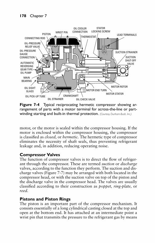
P1: GDZ/FFX P2: GDZ/FFX QC: GDZ/FFX T1: GDZ
GB076-07 GB076-Miller-Sample July 14, 2004 22:27 Char Count= 0
178 Chapter 7
LEAD TERMINALS
STATORLOCKING SCREW
OIL COOLERCONNECTIONWRIST PIN
THERMOSTATPISTON
CONNECTING ROD
OIL-PRESSURERELIEF VALVE
OIL-PRESSUREGAUGECONNECTION
AUTOMATICREVERSINGGEAR TYPEOIL PUMP
MAINBEARING
OIL SIGHTGLASS
OIL PICK-UP TUBEOIL STRAINER
CRANKSHAFTOIL CHECK VALVE
MOTOR END TURNMOTOR STATOR
MOTOR ROTOR
SUCTIONSHUT-OFF
VALVE
SUCTION STRAINER
Figure 7-4 Typical reciprocating hermetic compressor showing ar-rangement of parts with a motor terminal for across-the-line or part-winding starting and built-in thermal protection. (Courtesy Dunham-Bush, Inc.)
motor, or the motor is sealed within the compressor housing. If themotor is enclosed within the compressor housing, the compressoris classified as closed, or hermetic. The hermetic type of compressoreliminates the necessity of shaft seals, thus preventing refrigerantleakage and, in addition, reducing operating noise.
Compressor ValvesThe function of compressor valves is to direct the flow of refriger-ant through the compressor. These are termed suction or dischargevalves, according to the function they perform. The suction and dis-charge valves (Figure 7-7) may be arranged with both located in thecompressor head, or with the suction valve on top of the piston andthe discharge valve in the compressor head. The valves are usuallyclassified according to their construction as poppet, ring-plate, orreed.
Pistons and Piston RingsThe piston is an important part of the compressor mechanism. Itconsists essentially of a long cylindrical casting closed at the top andopen at the bottom end. It has attached at an intermediate point awrist pin that transmits the pressure to the refrigerant gas by means

P1: GDZ/FFX P2: GDZ/FFX QC: GDZ/FFX T1: GDZ
GB076-07 GB076-Miller-Sample July 14, 2004 22:27 Char Count= 0
Compressors for Air Conditioners 179
MOTOR ROTOR
MOTOR STATOR
CRANKSHAFT
PISTON
VALVE
SPRINGSUSPENSION
TERMINAL BOX
CONNECTING ROD
VALVE
Figure 7-5 Sectional view of vertical hermetic compressor.
of the connecting rod attached to the crankshaft. In this manner, thepumping action of the compressor provides the necessary circulatingfeature of the refrigerant in a mechanical refrigeration system.
Pistons employed in the majority of compressors are made fromthe best grade of cast iron. They are carefully machined, polished,and fitted to the cylinders at close tolerances. There are several differ-ent designs of pistons. Some early models were not equipped withpiston rings, but were lapped to the cylinder in a very close fit.

P1: GDZ/FFX P2: GDZ/FFX QC: GDZ/FFX T1: GDZ
GB076-07 GB076-Miller-Sample July 14, 2004 22:27 Char Count= 0
180 Chapter 7
OIL-PRESSURE FAILURE SWITCHSUCTION FILTER SCREENSUCTION SCALE TRAPSAFETY VALVE
CYLINDER HEADS
SAFETY HEAD SPRINGS
SUCTION AND DISCHARGE VALVESJACKETED CONTROL PLATESPISTON RINGSCYLINDER BLOCKSWRIST PINS
CONNECTING RODS
V-BELT WHEELCRANKCASE ACCESS PLATESCRANKSHAFTOIL PUMP
OIL FILTER SCREENOIL SIGHT GLASS
CRANKCASE
MANIFOLDING AND DISCHARGE STOP VALVE
Figure 7-6 Cutaway view of a Frick ellipse reciprocating compressorequipped for automatic operation. (Courtesy the Frick Company.)
RING PLATETHREADS
RIVETSCASE
LOCKINGSCREW
SECTIONOF PISTONSEAT
Figure 7-7 Sectional viewthrough a Garland valve showingarrangement of parts.
At present, however, two or more piston rings are employed, theirfunction being to ensure proper lubrication and sealing of the cylin-der walls.
When assembled, pistons should fit the cylinder walls so thatwhen inserted they do not drop of their own weight, but must beurged through with the fingers. This fit is usually obtained by allow-ing 0.0003 inch of clearance per inch of cylinder diameter. Thus,a 31/2-inch cylinder would have a 0.00105-inch clearance betweenpiston and cylinder wall (see Figure 7-8).

P1: GDZ/FFX P2: GDZ/FFX QC: GDZ/FFX T1: GDZ
GB076-07 GB076-Miller-Sample July 14, 2004 22:27 Char Count= 0
Compressors for Air Conditioners 181
VAPORINTAKE
DOWNSTROKE
VAPORDISCHARGE
UPSTROKE
Figure 7-8 Operation of the valves in a reciprocating compressor.
If cylinders are scored, they must be honed after reboring to en-sure a high degree of wall finish that maintains cylinder propor-tions over long periods. After rings have been fitted, the compres-sor should be operated overnight to permit the rings to wear in.The compressor should then be drained and flushed with petroleumspirits or dry-cleaning fluid and dehydrated before being returnedto service.
Connecting RodsThe connecting rod, as the name implies, serves as the connectinglink between the piston and the crankshaft. It transforms the rotarymotion of the crankshaft into the reciprocating motion of the piston.One end of the connecting rod is connected to the piston by meansof a hardened, ground, and highly polished steel wrist pin, and theother end is connected to the crankshaft (see Figure 7-9). Severaldifferent methods are used to secure the piston wrist pin and rod. Insome designs, the wrist pin is tightly clamped to the connecting rodwith the moving bearing surface in the piston, while others have abushing in the connecting rod.
CrankshaftsThe duty performed by this part of the compressor is to convertthe rotating motion of the crankshaft into the reciprocating motionof the piston. In its simplest form, it consists essentially of a shafthaving a lever or arm (known as a crank integral) attached at right

P1: GDZ/FFX P2: GDZ/FFX QC: GDZ/FFX T1: GDZ
GB076-07 GB076-Miller-Sample July 14, 2004 22:27 Char Count= 0
182 Chapter 7
Figure 7-9 Compressor piston and connecting rod arrangement.(Courtesy the Trane Company.)
angles to the shaft. The outer end of the lever has a pin that engageswith the large bearing on the connecting rod, as shown in Figure7-10. Crankshafts are commonly made of steel forgings, which aremachined to the proper tolerances for the main and connecting rodbearings. The double crank is employed in all two-cylinder com-pressors, while the single crank is used on the single-cylinder type.
JOURNALS
COUNTERWEIGHTS
Figure 7-10 Typical one-piece crankshaft. (Courtesy the Trane Company.)
Crankshafts are equipped with counterweights and are carefullybalanced to ensure smooth and vibrationless compressor operation.Some types of compressors are equipped with what is known asthe eccentric shaft. This is a different application of the crankshaft

P1: GDZ/FFX P2: GDZ/FFX QC: GDZ/FFX T1: GDZ
GB076-07 GB076-Miller-Sample July 14, 2004 22:27 Char Count= 0
Compressors for Air Conditioners 183
principle. It employs an assembly consisting of the main shaft (overwhich an eccentric is fitted) and an outer eccentric strap.
Shaft SealsThe function of the shaft seal in a refrigerating compressor is toprevent the gas from escaping from the compressor at the pointwhere the shaft leaves the compressor housing. This problem wasdifficult to solve in the early stages of the refrigeration industry.The shaft, of necessity, must revolve, and yet the refrigerant mustnot be allowed to escape (when there is a pressure within thecrankcase), nor must air be allowed to enter when the pressure of thecrankcase is below 0 lb. A typical compressor shaft seal is shown inFigure 7-11.
BEARINGHOUSING
CRANKSHAFT
MAINBEARING
FLEXIBLE STEELSEALING RING
WATERCONNECTION
OILPRESSURE
TO SEAL
KEY
FLYWHEELSHIELD4-SPRINGS
Figure 7-11 Compressor shaft seal showing cooling-water connec-tion. (Courtesy of Frick Company.)
The solution to the problem of crankshaft leaks was found in thedevelopment of a bellows-type seal, which is now a part of mostcompressors. The seal is an assembly of parts consisting of a specialbronze seal ring soldered to a bellows, which, in turn, is soldered

P1: GDZ/FFX P2: GDZ/FFX QC: GDZ/FFX T1: GDZ
GB076-07 GB076-Miller-Sample July 14, 2004 22:27 Char Count= 0
184 Chapter 7
to a brass seal flange. A spring surrounds the bellows, with one endresting against the seal ring and the other against the seal flange. Theface of the seal ring is lapped flat and smooth. When assembled inthe compressor, the seal ring presses against a shoulder on the shaft(which has also been lapped), forming a gas- and oil-tight joint atthis point. The bellows provides the degree of flexibility necessaryto keep the seal ring in perfect contact with the shaft, and the sealflange is clamped against a lead gasket around an opening in theside of the compressor.
Lubrication and CoolingThe method of lubrication depends largely on the size of the com-pressor. Forced lubrication is universally used on large compressors,while the splash method is used on smaller units. Large compres-sors are usually water-cooled, with the water jacket cooling onlythe cylinder walls or both the cylinder walls and compressor head.Small compressors are usually air-cooled with an extended finnedsurface cast on the cylinder exterior. In this connection, it should benoted that, although water-cooling is more effective, cylinder cool-ing removes only a portion of the superheat in the refrigerant gas.The removal of heat from the cylinder will also result in a decreasein the work of compression, with an accompanied reduction in thecondenser load.
Rotary CompressorsSince they are hermetically sealed, resulting in an improved drivemethod (the motor and compressor being located in a common en-closure), rotary compressors are presently manufactured in largequantities, particularly in fractional-tonnage applications. By defi-nition, a hermetic compressor is one in which the electric motor andcompressor are contained within the same pressure vessel, with themotor shaft integral with the compressor crankshaft. The motor isin constant contact with the refrigerant.
In operation, the rotary-type compressor performs the same func-tion as the reciprocating compressor. The compression of the gasestablishes a pressure difference in the system to create a flow ofrefrigerant from one part of the system to the other. The rotary-type compressor, however, employs a slightly different method ofaccomplishing the compression of the gas. The rotary compressorcompresses gas because of the movement of the rotor in relation tothe pump chamber.
The two types or configurations of rotary compressors are thestationary-blade rotary compressor and the rotating blade rotary

P1: GDZ/FFX P2: GDZ/FFX QC: GDZ/FFX T1: GDZ
GB076-07 GB076-Miller-Sample July 14, 2004 22:27 Char Count= 0
Compressors for Air Conditioners 185
compressor. Figure 7-12 is an example of the stationary blade type.Note how the sliding barrier operates inside the steel cylinder.
STEEL CYLINDER
SLIDING BARRIER
RING
CAM
MOTOR
Figure 7-12 Parts of a stationary blade rotary compressor.
The only moving parts in a stationary blade rotary compressorare a steel ring, an eccentric or cam, and a sliding barrier. Figure 7-13labels the parts of this type of operation, while Figure 7-14 showshow the rotation of the off-center cam compresses the gas refrigerantin the cylinder of the rotary compressor. The cam is rotated by anelectric motor. As the cam spins, it carries the ring with it. The ringrolls on its outer rim around the wall of the cylinder.
CYLINDERWALL
ROLLER
DISCHARGEPORT
BLADE
SPRING
INTAKEPORT
Figure 7-13 Parts labeled for a stationary blade rotary compressor.

P1: GDZ/FFX P2: GDZ/FFX QC: GDZ/FFX T1: GDZ
GB076-07 GB076-Miller-Sample July 14, 2004 22:27 Char Count= 0
186 Chapter 7
CYLINDER
CRESCENT-SHAPED SPACE
RING
Figure 7-14 Operationof the rotary compressor.
The gas must have a pathway to be brought into the chamber.Note that in Figure 7-15 the vapor comes in from the evaporatorand goes out to the condenser through holes that have been drilledin the compressor frame. Note that the gas is compressed by anoffset rotating ring. Figure 7-16 shows how the refrigerant vaporin the compressor is brought from the evaporator as the exit portis opening. When the compressor starts to draw the vapor fromthe evaporator, the barrier is held against the ring by a spring. Thisbarrier separates the intake and exhaust ports. As the ring rollsaround the cylinder, it compresses the gas and passes it on to thecondenser (see Figure 7-17). The finish of the compression portionof the stroke or operation is shown in Figure 7-18. The ring rotatesaround the cylinder wall. It is held in place by the spring tension of
REFRIGERANT VAPOR FROM EVAPORATOR
TO CONDENSER
Figure 7-15 Beginning of the compression phase in a rotary comp-ressor.
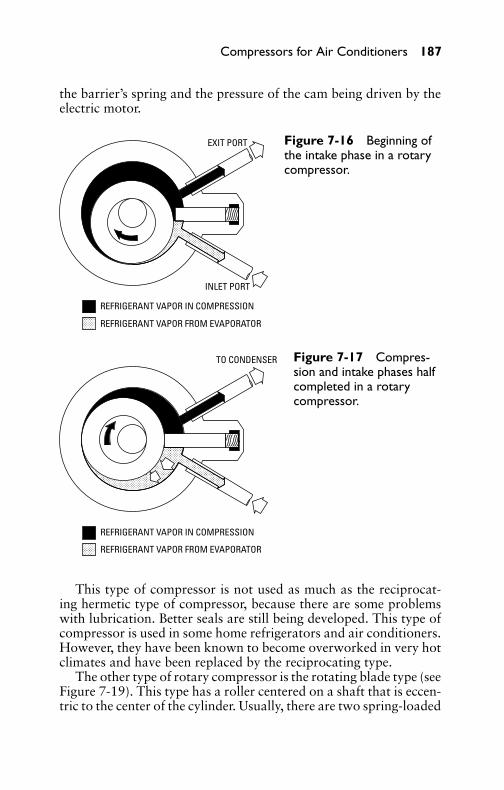
P1: GDZ/FFX P2: GDZ/FFX QC: GDZ/FFX T1: GDZ
GB076-07 GB076-Miller-Sample July 14, 2004 22:27 Char Count= 0
Compressors for Air Conditioners 187
the barrier’s spring and the pressure of the cam being driven by theelectric motor.
EXIT PORT
INLET PORT
REFRIGERANT VAPOR IN COMPRESSION
REFRIGERANT VAPOR FROM EVAPORATOR
Figure 7-16 Beginning ofthe intake phase in a rotarycompressor.
REFRIGERANT VAPOR IN COMPRESSION
REFRIGERANT VAPOR FROM EVAPORATOR
TO CONDENSER Figure 7-17 Compres-sion and intake phases halfcompleted in a rotarycompressor.
This type of compressor is not used as much as the reciprocat-ing hermetic type of compressor, because there are some problemswith lubrication. Better seals are still being developed. This type ofcompressor is used in some home refrigerators and air conditioners.However, they have been known to become overworked in very hotclimates and have been replaced by the reciprocating type.
The other type of rotary compressor is the rotating blade type (seeFigure 7-19). This type has a roller centered on a shaft that is eccen-tric to the center of the cylinder. Usually, there are two spring-loaded

P1: GDZ/FFX P2: GDZ/FFX QC: GDZ/FFX T1: GDZ
GB076-07 GB076-Miller-Sample July 14, 2004 22:27 Char Count= 0
188 Chapter 7
EXIT PORT
INLET PORT
REFRIGERANT VAPOR IN COMPRESSION
REFRIGERANT VAPOR FROM EVAPORATOR
Figure 7-18 Finish of thecompression phase of therotary compressor.
CYLINDERWALL
BLADESDISCHARGEPORT
CONTACTPOINT
ROLLER
INTAKEPORT
Figure 7-19 Rotating blade compressor.
roller blades, mounted 180◦ apart. The blades sweep the sides of thecylinder. The roller is so mounted that it touches the cylinder at apoint between the intake and discharge ports. As the roller rotates,vapor moves into the cylinder through the intake port and is trappedin a space between the cylinder wall, the blade, and the point of con-tact between the roller and the cylinder. Vapor is compressed as thenext blade passes the contact point and the vapor space becomessmaller and smaller. When the vapor has been compressed to a cer-tain pressure, it leaves by way of the exhaust port on its way to the

P1: GDZ/FFX P2: GDZ/FFX QC: GDZ/FFX T1: GDZ
GB076-07 GB076-Miller-Sample July 14, 2004 22:27 Char Count= 0
Compressors for Air Conditioners 189
condenser. This type of rotary compressor, like the stationary blademodel, requires extremely close tolerances.
Some manufacturers make rotary-blade compressors for com-mercial applications. They are used primarily with ammonia. Thus,there is no copper or copper alloy tubing or parts. Most of the am-monia tubing and working metal is stainless steel.
Scroll CompressorsThe scroll compressor (see Figure 7-20) has been utilized by theindustry in response to increasing the efficiency of air-conditioningequipment in order to meet the U.S. Department of Energy Standardsof 1992, which apply to all air conditioners. All equipment musthave a Seasonal Energy Efficiency Ratio (SEER) of 10 or better. Thehigher the number, the more efficient the unit is. The scroll compres-sor seems to be the answer to more efficient compressor operation.
Scroll Compression ProcessFigure 7-21 shows how two spiral-shaped members fit together. Abetter view is shown in Figure 7-22. The two members fit togetherforming crescent-shaped gas pockets. One member remains station-ary, while the second member is allowed to orbit relative to thestationary member.
This movement draws gas into the outer pocket created by thetwo members, sealing off the open passage. As the spiral motioncontinues, the gas is forced toward the center of the scroll formas the pocket continuously becomes smaller in volume, creating in-creasingly higher gas pressures. At the center of the pocket, the high-pressure gas is discharged from the port of the fixed scroll member.During the cycle, several pockets of gas are compressed simultane-ously, providing a smooth, nearly continuous compression cycle.
This results in a 10 to 15 percent more efficient operation thanwith the piston compressors. A smooth, continuous compressionprocess means very low flow losses. No valves are required, thuseliminating all valve losses. Suction and discharge locations areseparate. This substantially reduces heat transfer between suctionand discharge gas. There is no re-expansion volume. This increasesthe compressor’s heat pump capacity in low-ambient operation. In-creased heat pump capacity in low-ambient temperatures reducesthe need for supplemental heat when temperatures drop.
During summer, this means less cycling at moderate temperaturesand allows better dehumidification to keep the comfort level high.When temperatures rise, the scroll compressor provides increasedcapacity for more cooling.
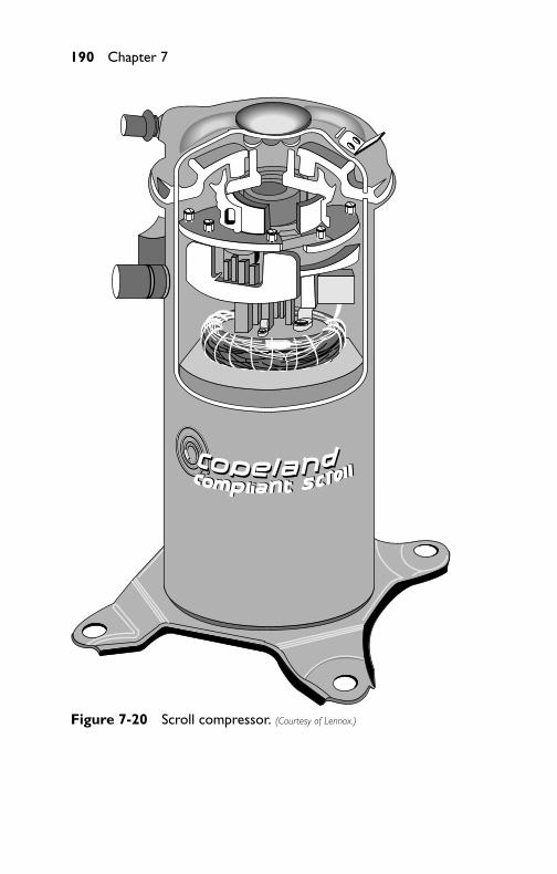
P1: GDZ/FFX P2: GDZ/FFX QC: GDZ/FFX T1: GDZ
GB076-07 GB076-Miller-Sample July 14, 2004 22:27 Char Count= 0
190 Chapter 7
Figure 7-20 Scroll compressor. (Courtesy of Lennox.)

P1: GDZ/FFX P2: GDZ/FFX QC: GDZ/FFX T1: GDZ
GB076-07 GB076-Miller-Sample July 14, 2004 22:27 Char Count= 0
Compressors for Air Conditioners 191
Figure 7-21 Scroll compression process. (Courtesy of Lennox.)
Figure 7-22 Two halves of the scroll compressor. (Courtesy of Lennox.)
During the winter, the scroll compressor heat pumps deliver morewarm air to the conditioned space than conventional models.
OperationThe scroll compressor has no valves and low gas pulses, which al-lows for smooth and quiet operation. It has fewer moving parts(only two gas compression parts as compared to 15 components inpiston-type compressors) and requires no compressor start compo-nents. There is no accumulator or crankcase heater required, nor isa high-pressure cut-out needed.

P1: GDZ/FFX P2: GDZ/FFX QC: GDZ/FFX T1: GDZ
GB076-07 GB076-Miller-Sample July 14, 2004 22:27 Char Count= 0
192 Chapter 7
The radial compliance design features a superior liquid-handlingcapacity. This allows small amounts of liquid and dirt to passthrough without damaging the compressor. At the same time, thiseliminates high stress on the motor and provides high reliability.Axial compliance allows the scroll tips to remain in continuouscontact, ensuring minimal leakage. Performance actually gets betterover time, because there are no seals to wear and cause gas leakage.
Scroll Compressor ModelsExamples of air-conditioner units with the scroll compressor are theLennox HP-20 and HS-22.
HP-20 ModelThe HP-20 is also designed for efficient use in heat pump instal-lations (see Figure 7-23). It has a large coil surface area to delivermore comfort per watt of electricity. Copper tube/aluminum fin coilprovides effective heat transfer for efficient heating and cooling (seeFigure 7-24). The scroll compressor technology has been around fora long time, but this was one of the first to make use of it in heatpumps.
HS-22 ModelThe HS-22 model also uses a Copeland-compliant scroll compressor(see Figure 7-25). The insulated cabinet allows it to operate withoutdisturbing the neighbors in closely arranged housing developments.The cabinet with vertical air discharge creates a unit with soundratings as low as 7.2 bells.
The condensing unit has a SEER rating as high as 13.5. The scrollcompressor is highly efficient with a large double-row condenser coilto increase the efficient use of energy even more.
Centrifugal CompressorsCentrifugal compressors are essentially high-speed machines andbest suited for steam-turbine drives. Because they are designed forthe same high speed as the turbine, they may be directly connected.Where high-pressure steam is generated, the turbine can act as areducing valve, and the low-pressure steam that leaves the turbinecan be used for heating and other purposes. In smaller sizes, a greatmany applications are driven by electric motors and equipped withgear-type speed increasers. Centrifugal compressors are used withlow-pressure refrigerants, and both evaporator and condenser usu-ally work below atmospheric pressure.
Compression of the refrigerant is accomplished by means of cen-trifugal force. Because of this, centrifugal compressors are best suitedfor large refrigerant volumes and low-pressure differentials. They

P1: GDZ/FFX P2: GDZ/FFX QC: GDZ/FFX T1: GDZ
GB076-07 GB076-Miller-Sample July 14, 2004 22:27 Char Count= 0
Compressors for Air Conditioners 193
1
2
3
4
5
Figure 7-23 HP-20 model with a heavy-duty scroll compressor: (1)cabinet, (2) coil area, (3) copper tubing, (4) fan, (5) scroll compressor.(Courtesy of Lennox.)
are well-suited to low-temperature refrigerating cycles, especiallythose using petroleum or halogenated hydrocarbons as a refrigerant.
Centrifugal-compressor installations are economically advanta-geous where steam-turbine drive is permitted, since the installa-tion and labor required for such an installation is relatively smallcompared to that required for a comparable gas-engine–driven

P1: GDZ/FFX P2: GDZ/FFX QC: GDZ/FFX T1: GDZ
GB076-07 GB076-Miller-Sample July 14, 2004 22:27 Char Count= 0
Figure 7-24 Copper tubingin the condenser withaluminum fins. (Courtesy of Lennox.)
12
3
4
6
5
Figure 7-25 HS-22 model: (1) scroll compressor, (2) cabinet, (3) fan,(4) copper tubing in condenser, (5) coil area in compressor, (6) filter-drier. (Courtesy of Lennox.)
194
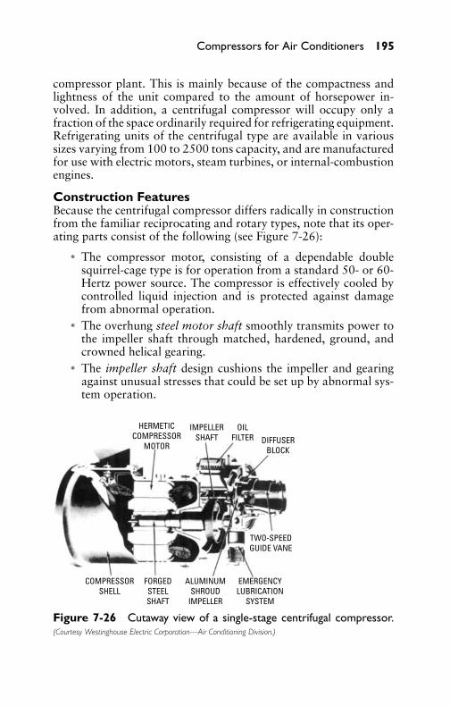
P1: GDZ/FFX P2: GDZ/FFX QC: GDZ/FFX T1: GDZ
GB076-07 GB076-Miller-Sample July 14, 2004 22:27 Char Count= 0
Compressors for Air Conditioners 195
compressor plant. This is mainly because of the compactness andlightness of the unit compared to the amount of horsepower in-volved. In addition, a centrifugal compressor will occupy only afraction of the space ordinarily required for refrigerating equipment.Refrigerating units of the centrifugal type are available in varioussizes varying from 100 to 2500 tons capacity, and are manufacturedfor use with electric motors, steam turbines, or internal-combustionengines.
Construction FeaturesBecause the centrifugal compressor differs radically in constructionfrom the familiar reciprocating and rotary types, note that its oper-ating parts consist of the following (see Figure 7-26):� The compressor motor, consisting of a dependable double
squirrel-cage type is for operation from a standard 50- or 60-Hertz power source. The compressor is effectively cooled bycontrolled liquid injection and is protected against damagefrom abnormal operation.� The overhung steel motor shaft smoothly transmits power to
the impeller shaft through matched, hardened, ground, andcrowned helical gearing.� The impeller shaft design cushions the impeller and gearing
against unusual stresses that could be set up by abnormal sys-tem operation.
HERMETICCOMPRESSOR
MOTOR
IMPELLERSHAFT
OILFILTER DIFFUSER
BLOCK
TWO-SPEEDGUIDE VANE
EMERGENCYLUBRICATION
SYSTEM
ALUMINUMSHROUD
IMPELLER
FORGEDSTEELSHAFT
COMPRESSORSHELL
Figure 7-26 Cutaway view of a single-stage centrifugal compressor.(Courtesy Westinghouse Electric Corporation—Air Conditioning Division.)

P1: GDZ/FFX P2: GDZ/FFX QC: GDZ/FFX T1: GDZ
GB076-07 GB076-Miller-Sample July 14, 2004 22:27 Char Count= 0
196 Chapter 7
� Emergency lubrication is provided by a built-in emergency sys-tem. Should a power failure occur, oil under pressure is avail-able for the coast-down period.� Oil is supplied to the bearings and is cleaned by a 10-µ oil filter.
A check valve on the discharge side of the filter reservoir al-lows easy filter replacement without the need for system pumpdown.� The movable diffuser block is positioned by the guide-vane
piston. As loads vary, the diffuser block is moved to matchthe diffuser passage to the gas flow and to allow quiet, stableoperation from 1 to 100 percent of unit capacity.� A two-speed, hydraulically operated guide-vane activating pis-
ton positions the vanes at speed one (the normal response tovariations in the chiller water temperature leaving the unit).A built-in compensating control allows automatic override ofnormal operation and quick response at speed two to close thevalves for low suction pressure or current-limiting duty.� The inlet guide vanes modulate the compressor capacity and
direct the refrigerant gas into the impeller in a manner thatminimizes refrigerant pressure losses.� An aluminum closed-shroud impeller is precision cast. It in-
corporates an unusual noise-abatement system. It is mountedon the impeller shaft by means of a rugged self-centering typeof friction mounting.
Lubrication SystemA separately driven hermetic oil-pump assembly supplies oil at con-trolled temperature and pressure to all bearing surfaces, and is thesource of hydraulic pressure for the capacity-control system. Theoil pump is automatically started. It must run for a fixed period be-fore the compressor is started and after it has stopped. In addition,temperature and pressure controls prevent the compressor fromoperating unless oil pressure and temperature are at satisfactorylevels.
Oil is collected from a well located at the bottom of the gearcasing and is returned to the oil pump through an external oil line.Any refrigerant returning to the pump with the oil is purged from thepump housing after entrained oil has been separated. Oil is separatedas the refrigerant gas passes through an unusual centrifuge type ofoil separator that is mounted on the pump motor rotor, as shownin Figure 7-27.
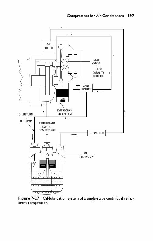
P1: GDZ/FFX P2: GDZ/FFX QC: GDZ/FFX T1: GDZ
GB076-07 GB076-Miller-Sample July 14, 2004 22:27 Char Count= 0
Compressors for Air Conditioners 197
OIL TOCAPACITYCONTROL
OIL RETURNTO
OIL PUMPREFRIGERANT
GAS TO COMPRESSOR
EMERGENCYOIL SYSTEM
OILSEPARATOR
OIL COOLER
VANECONTROL
INLETVANES
OILFILTER
Figure 7-27 Oil-lubrication system of a single-stage centrifugal refrig-erant compressor.
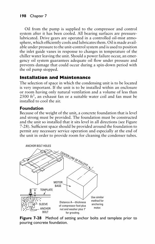
P1: GDZ/FFX P2: GDZ/FFX QC: GDZ/FFX T1: GDZ
GB076-07 GB076-Miller-Sample July 14, 2004 22:27 Char Count= 0
198 Chapter 7
Oil from the pump is supplied to the compressor and controlsystem after it has been cooled. All bearing surfaces are pressure-lubricated. Drive gears are operated in a controlled oil-mist atmo-sphere, which efficiently cools and lubricates them. Oil is made avail-able under pressure to the unit-control system and is used to positionthe inlet guide vanes in response to changes in temperature of thechiller water leaving the unit. Should a power failure occur, an emer-gency oil system guarantees adequate oil flow under pressure andprevents damage that could occur during a spin-down period withthe oil pump stopped.
Installation and MaintenanceThe selection of space in which the condensing unit is to be locatedis very important. If the unit is to be installed within an enclosureor room having only natural ventilation and a volume of less than2500 ft3, an exhaust fan or a suitable water coil and fan must beinstalled to cool the air.
FoundationBecause of the weight of the unit, a concrete foundation that is leveland strong must be provided. The foundation must be constructedand the unit so installed that it sits level in all directions (see Figure7-28). Sufficient space should be provided around the foundation topermit any necessary service operation and especially at the end ofthe unit in order to provide room for cleaning the condenser tubes.
Use similarmethod foranchoring
motor.
Distance A—thicknessof compressor foot plus nut and washer plus 1"
for grouting.
ANCHOR BOLT HOLES
MOTORBASE
ANCHORBOLT
CENTER LINE OF PULLEYS
SLEEVE
TEMPLATEA
Figure 7-28 Method of setting anchor bolts and template prior topouring concrete foundation.
P1: GDZ/FFX P2: GDZ/FFX QC: GDZ/FFX T1: GDZ
GB076-07 GB076-Miller-Sample July 14, 2004 22:27 Char Count= 0
Compressors for Air Conditioners 199
Motor and BeltsIn condensing-unit installations having belted compressors, the pro-cedure is generally as follows:
1. Align the motor pulley with the compressor flywheels bystretching a string from the outer edge of one flywheel to theouter edge of the other (or, by using a long rigid straight edge).It may be necessary to loosen the motor mounting bolts andslide the motor forward or backward to get the pulley prop-erly aligned. Do not slide the pulley further out or closer in onthe motor shaft for this initial alignment. A slight adjustmentmay be made in this manner, if necessary, after the condensingunit is assembled and operating.
2. To install the belts, start by placing a belt in the pulley groovenearest the motor. Then place the belt in the flywheel groovethat lines up with this rear groove in the pulley. With the motormounting base in its lowest position, the belt may be put onusing only the hands. Never use a pry bar, screwdriver, or woodstrips, because this will result in broken fibers and shorten thebelt life.
3. Adjust the belt tension by raising the motor mounting baseby means of the nuts on the adjusting screws. Proper tensionwill allow some give in the belt when depressed with the hand.Be sure that all four corners of the motor base are the samedistance above the condensing-unit frame, because the motormust be level. It may be necessary to move the motor slightly atthis time to equalize the tension in the belt to the compressor.
Compressor Flow-Back ProtectionIn most air-conditioning and refrigeration systems, it is possible tocontrol the refrigerant feed so that liquid refrigerant does not re-turn to the compressor during operation. Some systems have pooroperation of the expansion valve. Also, some have sudden changesin loading and will periodically return liquid refrigerant to the com-pressor. This is not usually in sufficient quantities to do real damage.However, there are certain systems that, by their very design, willperiodically flood the compressor with excessive amounts of liquidrefrigerant. Principally, these prove to be systems in which there is aperiodic reversal of the refrigerant cycle to do one of the following:� Provide hot gas for defrosting an evaporator.� Furnish heat for release purposes in ice-making apparatus.� Change from cooling to heating cycle, or vice versa, in heat-
pump systems.

P1: GDZ/FFX P2: GDZ/FFX QC: GDZ/FFX T1: GDZ
GB076-07 GB076-Miller-Sample July 14, 2004 22:27 Char Count= 0
200 Chapter 7
These systems are almost identical in operation and in the effecton the compressor. Consider an air-source heat pump for a typicalanalysis of what happens. The flow back occurs when reversingthe cycle in either direction. During the cooling cycle, the outdoorcoils act as condensers and have warm liquid continually drainingfrom them. The lines to which the thermal expansion-valve bulbsare strapped are now hot-gas lines and are hot. When the cyclereverses to heating, the outdoor coils change from condensers toevaporators. The liquid that has been draining from them duringthe condensing cycle is now dumped into the suction line. Of evengreater significance, the thermal expansion valves also open wideas the result of their bulbs being on warm lines (lines that werepreviously hot-gas lines). Therefore, these valves will flow throughuntil control is re-established at the bulbs. The two effects constitutea substantial liquid flow back through the suction line.
When there is no way to control the hazard of periodic flowbackof substantial proportions through the suction line, it is necessaryto take measures to protect the compressor against it; otherwise,compressor life will be materially shortened. The most satisfactorymethod appears to be a trap arrangement that catches the liquidflowback and may do one of the following:
� Meter it slowly into the suction line when it is cleaned up witha liquid-suction heat interchanger.� Evaporate 100 percent of the liquid in the trap itself and au-
tomatically return the oil to the suction line.
Valve MaintenanceSometimes the suction-valve reed is held off its seat by corrosion anddirt lodged under it, thus leaving the cylinder open to the low side.In this case, there will be no refrigeration, the condenser will not getwarm, and the power consumption by the drive motor will be low.To determine if the inlet valve is causing these conditions, connectthe compound and pressure gage, and start the unit. The pressuregage will not show an increase in pressure, and the compound gagewill not show any decrease in pressure and will fluctuate. Flushingthe valve may wash the obstruction away and permit it to functionnormally. If the discharge valve is held open by something lodgedunder it (such as corrosion or dirt), the cylinder will remain open tothe high side and there will be no refrigeration.
Connect the compound and pressure gage to determine if thedischarge valve leaks. Operate the unit until the low-side pressureis reduced to normal. Shut off the unit. Immediately place your ear
P1: GDZ/FFX P2: GDZ/FFX QC: GDZ/FFX T1: GDZ
GB076-07 GB076-Miller-Sample July 14, 2004 22:27 Char Count= 0
Compressors for Air Conditioners 201
close to the compressor. If the valve leaks, a hissing noise producedby escaping gas can be heard. The low-side pressure will rise rapidly,and the high-side pressure will fall rapidly, equalizing the pressures.The rapidity of this action will determine how badly the valve leaks.
Shaft-Seal LeaksTo determine whether a compressor is leaking at the seal, proceedas follows. Close the shutoff valves by turning the stem clockwise asfar as possible. To ensure adequate refrigerant pressure in the com-pressor crankcase and on the seal-bearing face, attach a refrigerantdrum containing the correct refrigerant to the suction shutoff valveoutlet port. In making this connection, there should be a gage in theline from the drum to the compressor to determine accurately thepressure in the compressor.
Test pressures for this purpose should be approximately 70 to80 lb. If the compressor is located in a cool location, it may be neces-sary to raise the pressure in the drum by adding heat. In this process,care must be taken not to exceed 100 psi, since greater pressure maydamage the bellows assembly of the seal. With this pressure on thecrankcase of the compressor, test for leaks with a halide torch, mov-ing the finder tube close around the seal nut, crankshaft, seal-plategasket, and where the seal comes in contact with the seal plate. Ifthis does not disclose a leak, turn the flywheel over slowly by hand,holding the finder tube close to the aforementioned parts.
After a leak has been detected, locate the exact place where it isleaking, if possible. If the leak is around the seal-plate gasket, replacethe gasket. If the leak should be at the seal seat or nut, replace with anew seal plate, gasket, and seal assembly. To replace the seal, observethe following instructions:
1. Remove the compressor from the condensing unit in the usualmanner.
2. Remove the flywheel, using a puller. Leave the flywheel nuton the crankshaft so that the wheel puller will not distort thethreads.
3. Remove the seal guard, seal nut, and seal assembly.4. Remove the seal plate and gasket.5. When assembling the seal, put a small quantity of clean com-
pressor oil on the seal face (both plate and seal).6. Reverse these operations to reassemble. Make sure the seal
plate is bolted in place and the seal guard is at the top.
P1: GDZ/FFX P2: GDZ/FFX QC: GDZ/FFX T1: GDZ
GB076-07 GB076-Miller-Sample July 14, 2004 22:27 Char Count= 0
202 Chapter 7
Compressor KnocksA knock in the compressor may be caused by a loose connecting rod,eccentric strip and rod, eccentric disk, piston pin, crankshaft, or toomuch oil in the system. A compressor knock can be determined byplacing the point of a screwdriver against the crankcase and yourear against the handle. A knock can then very easily be heard. Itwill not be possible to determine what causes the knock before thecompressor is disassembled. Sometimes it may be possible to deter-mine a looseness of the aforementioned parts without completelydisassembling the compressor.
First, remove the cylinder head and valve plate to expose the headof the piston. Now, start the motor and press down on the top of thepiston with the finger. Any looseness can be felt at each stroke of thepiston. The loose part should be replaced. It is always good to checkthe compressor oil level first before analyzing and determining thecompressor repairs. Oil knocks are usually caused by adding toomuch oil in servicing.
It should never be necessary to add oil to a system unless therehas been a leakage of oil. A low charge is sometimes diagnosed aslack of oil. Always ensure that a low oil level is actually caused bylack of oil rather than a low charge before adding oil to the system.
Stuck or Tight CompressorThe reason for a compressor being stuck-up is usually the result ofmoisture in the system, or a lack of lubrication. When this occurs,the compressor should be thoroughly cleaned out. The compressorshould be completely disassembled and the parts thoroughly cleanedand refitted. New oil and refrigerant should be put into the cleanedsystem. A tight compressor will result when a cylinder head, sealcover, or similar part has been removed and not replaced carefully,or when the screws have been tightened unevenly.
Compressor RemovalTo remove a compressor from the unit, proceed as follows:
1. Attach a compound gage to the suction-line valve. Close thesuction-line shutoff valve and run the compressor until 20 to25 inches of vacuum is obtained. Then close the dischargeshutoff valve. Before removing any fittings, crank the suction-line valve to bring the gage reading back to zero.
2. Before removing the service valves, loosen the pressure gageand relieve the pressure in the head of the compressor. Removethe belt and cap screws holding the suction, and discharge
P1: GDZ/FFX P2: GDZ/FFX QC: GDZ/FFX T1: GDZ
GB076-07 GB076-Miller-Sample July 14, 2004 22:27 Char Count= 0
Compressors for Air Conditioners 203
valves to the compressor. If the compressor is to be taken awayfrom the premises for repairs, place service valves over both thedischarge and suction-line openings to prevent air and mois-ture from entering and oil from leaking out. Loosen the fournuts that hold the compressor to the base, and bend the tubingaway from the compressor just enough to permit the assem-bly to be lifted out. Care should be taken not to loosen themounting pads and washers on which the compressor rests.
Compressor ReplacementThe reinstallation of a compressor is roughly a reversal of the pro-cess of removing it. First, place the mounting pads and washers inposition. Place the compressor carefully on the base in the sameposition it occupied before removal. Bolt the compressor in place.Replace the suction and discharge valves, using new gaskets. Afterthe compressor and valves are bolted in place, the compressor mustbe evacuated to remove the air.
Compressor StartupWhen starting a water-cooled compressor after winter shutdown,the following procedure is suggested:
1. Install a pressure gage on the condenser, and check for pres-sure. If there is no pressure in the condenser, determine howthe charge was lost and repair the leak before opening anyvalves.
2. Permit the refrigerant to flow through the system. To do this,open the liquid-line valves.
3. Check the entire system for refrigerant leaks, using a halideleak detector.
4. If the system is gas tight, connect the water lines, open the handvalve in the water lines, and open the discharge and suctionvalves.
CautionBe sure the condenser has not been frozen before turning on thewater.
5. Install the belts and check for correct tension after a shortperiod of operation.
6. Check the motor for oiling. If old oil is heavy or dirty, replacewith new oil of the proper viscosity.

P1: GDZ/FFX P2: GDZ/FFX QC: GDZ/FFX T1: GDZ
GB076-07 GB076-Miller-Sample July 14, 2004 22:27 Char Count= 0
204 Chapter 7
Winter Shutdown of Water-Cooled CompressorsWhere water-cooled refrigeration and air-conditioning systems arenot operated in the winter, it is necessary to service them beforediscontinuing their operation. They should be pumped down, waterdrained from the condensers and piping, belts loosened, and motorsoiled. The compressor should be thoroughly tested for leaks, andany found should be corrected.
To pump down and discontinue service, attach head and suctiongages, and close the liquid shutoff valve at the receiver. Run thecompressor until a suction pressure of from 2 to 5 psig is obtained.If, on stopping the compressor, the suction pressure rises, repeatuntil this pressure is steady. Close the suction and discharge shutoffvalves to confine the refrigerant charge in the receiver. Open themain switch and be sure to tag it with a warning not to start thecompressor without first opening the discharge and suction stopvalves, because damage to the compressor may result. Tighten allpacking nuts on valve stems. Cap all valve stems tightly.
The condenser is usually of sufficient capacity to hold the com-plete charge. However, if it is not, the overcharge must be pumpedinto an empty drum. Never fill a receiver completely with a liquid re-frigerant (indicated by a rise in head-gage pressure above the safetycutout pressure) so that no gas space exists. If the compressor roomtemperature increases, there is danger of rupturing the receiver. Shutoff the water supply to the compressor, and disconnect the outlet wa-ter line from the condenser. This will allow the water to drain fromthe condenser. After the water has all drained out, connect the airline or an automobile tire pump to the blowout plug, and proceed toforce the remaining water (if any) out of the condenser. Condenserswith removable heads can be effectively drained by shutting off thewaste supply and removing the condenser heads, thus allowing allthe water to drain.
On compressors of large capacity, it will be necessary to arrangefor a connection to accommodate the airline, or pump. After allwater has been forced from the condenser, it is recommended thatall water lines be disconnected from the condenser and the watervalves drained by removing the drain plug from the bottom of thewater valves. For frequent and quick draining, it is suggested that atee and drain valve be installed between the water-regulating valveand condenser inlet. The safest, surest way to prepare condensersfor winter shutdown is to flush them out with an antifreeze solution.After the condenser has been treated with the antifreeze solution anddrained, the condenser inlet and outlet water connections should beplugged in order to maintain the remaining antifreeze solution in
P1: GDZ/FFX P2: GDZ/FFX QC: GDZ/FFX T1: GDZ
GB076-07 GB076-Miller-Sample July 14, 2004 22:27 Char Count= 0
Compressors for Air Conditioners 205
the condenser. Remove the belts from the compressor motor, butnot from the flywheel, so that they will not take a permanent set.It is also advisable to oil the motor to protect the bearings fromcorrosion.
Compressor CharacteristicsThis section discusses some common characteristics of compressors.
Compressor PerformanceThe performance of a compressor is measured by its ability to pro-vide the maximum refrigeration effect with the least power input.Other desirable factors are maximum trouble-free life expectancy atthe lowest possible cost and a wide range of operating conditions.The performance factor of a compressor may be written as follows:
Performance factor = capacity, Btupower input, watts
Compressor CapacityCapacity of a compressor means the useful refrigeration effect thatcan be accomplished. It is equal to the difference in the total enthalpybetween the refrigerant liquid at a temperature corresponding to thepressure leaving the compressor and the refrigerant vapor enteringthe compressor. It is measured in Btu.
Mechanical EfficiencyMechanical efficiency of a compressor is defined as the ratio of thework delivered to the gas (as obtained by an indicator diagram) tothe work delivered to the compressor shaft.
Volumetric EfficiencyVolumetric efficiency is defined as the ratio of the actual volumeof a refrigerant gas pumped by the compressor to the volume dis-placed by the compressor piston. The compression ratio of a com-pressor is the ratio of the absolute head pressure to the absolutesuction pressure. Factors determining compressor efficiency includethe clearance volume above the piston, clearance between the pistonand the cylinder walls, valve-spring tension, and valve leakage. Fora given compressor, the effect of compressor efficiency because ofdesign factors is constant, and volumetric efficiency will vary almostinversely with the compression ratio.
Compressor Efficiency TestAn efficiency test generally means a check on the relative amount ofuseful work that the compressor will accomplish. Strictly speaking,

P1: GDZ/FFX P2: GDZ/FFX QC: GDZ/FFX T1: GDZ
GB076-07 GB076-Miller-Sample July 14, 2004 22:27 Char Count= 0
206 Chapter 7
the efficiency of any machine is taken as the ratio of the poweroutput to the power input in the same units. This is usually writtenas follows:
Efficiency = outputinput
Factors that determine the efficiency of a compressor include thefollowing:� The degree to which the piston valve holds closed on the up
stroke� The degree to which the discharge valve holds tight when the
piston is on the down stroke
To test the compressor efficiency, proceed in the followingmanner:
1. Stop the compressor, and install a compound gage on thesuction-line valve.
2. Close the suction valve, and operate the compressor untilabout a 25-inch vacuum is obtained on the compound gage.Then stop the unit, and note the gage readings. If the compres-sor will not pull a 25-inch vacuum or better, it is an indicationthat air is leaking back by the discharge valve and leaking bythe piston valve.
3. If the head pressure drops and the vacuum-gage reading re-mains practically constant, this indicates that there is an ex-ternal leak at one of the points on the head of the compressoror at the gage and shutoff-valve connection.
4. To repair either a leaky suction or discharge valve, remove thehead of the compressor and carefully remove the discharge-valve plate. In disassembling the discharge valve, cautionshould be used not to disturb the actual conditions prevail-ing during the test. It is possible for some dirt, scale, or otherforeign matter to get under the valve disk and on the seat,causing poor performance. If there is no evidence of dirt orforeign matter, check the seat on both the discharge-valve andpiston assembly for low spots or scratches. If these are found,replace the disks or the complete valve plate.
Generally, the trouble can be found at either the suction valveor the discharge valve. Badly scored seats on either the discharge orsuction valve require replacing with a new assembly. The removal ofdeep scores changes the valve lift, further endangering the efficiency.
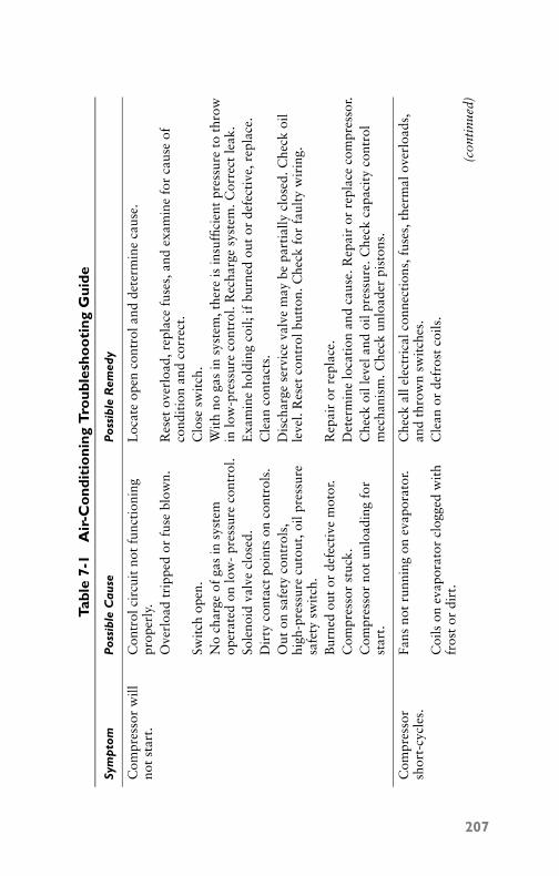
P1: GDZ/FFX P2: GDZ/FFX QC: GDZ/FFX T1: GDZ
GB076-07 GB076-Miller-Sample July 14, 2004 22:27 Char Count= 0
Tabl
e7-
1A
ir-C
ond
itio
ning
Tro
uble
sho
oti
ngG
uide
Sym
pto
mP
ossi
ble
Cau
seP
ossi
ble
Rem
edy
Com
pres
sor
will
not
star
t.C
ontr
olci
rcui
tno
tfu
ncti
onin
gpr
oper
ly.
Loc
ate
open
cont
rola
ndde
term
ine
caus
e.
Ove
rloa
dtr
ippe
dor
fuse
blow
n.R
eset
over
load
,rep
lace
fuse
s,an
dex
amin
efo
rca
use
ofco
ndit
ion
and
corr
ect.
Swit
chop
en.
Clo
sesw
itch
.N
och
arge
ofga
sin
syst
emop
erat
edon
low
-pr
essu
reco
ntro
l.W
ith
noga
sin
syst
em,t
here
isin
suffi
cien
tpr
essu
reto
thro
win
low
-pre
ssur
eco
ntro
l.R
echa
rge
syst
em.C
orre
ctle
ak.
Sole
noid
valv
ecl
osed
.E
xam
ine
hold
ing
coil;
ifbu
rned
out
orde
fect
ive,
repl
ace.
Dir
tyco
ntac
tpo
ints
onco
ntro
ls.
Cle
anco
ntac
ts.
Out
onsa
fety
cont
rols
,hi
gh-p
ress
ure
cuto
ut,o
ilpr
essu
resa
fety
swit
ch.
Dis
char
gese
rvic
eva
lve
may
bepa
rtia
llycl
osed
.Che
ckoi
lle
vel.
Res
etco
ntro
lbut
ton.
Che
ckfo
rfa
ulty
wir
ing.
Bur
ned
out
orde
fect
ive
mot
or.
Rep
air
orre
plac
e.C
ompr
esso
rst
uck.
Det
erm
ine
loca
tion
and
caus
e.R
epai
ror
repl
ace
com
pres
sor.
Com
pres
sor
not
unlo
adin
gfo
rst
art.
Che
ckoi
llev
elan
doi
lpre
ssur
e.C
heck
capa
city
cont
rol
mec
hani
sm.C
heck
unlo
ader
pist
ons.
Com
pres
sor
shor
t-cy
cles
.Fa
nsno
tru
nnin
gon
evap
orat
or.
Che
ckal
lele
ctri
calc
onne
ctio
ns,f
uses
,the
rmal
over
load
s,an
dth
row
nsw
itch
es.
Coi
lson
evap
orat
orcl
ogge
dw
ith
fros
tor
dirt
.C
lean
orde
fros
tco
ils.
(con
tinu
ed)
207

P1: GDZ/FFX P2: GDZ/FFX QC: GDZ/FFX T1: GDZ
GB076-07 GB076-Miller-Sample July 14, 2004 22:27 Char Count= 0
Tabl
e7-
1(c
onti
nued
)
Sym
pto
mP
ossi
ble
Cau
seP
ossi
ble
Rem
edy
The
rmal
bulb
onex
pans
ion
valv
eha
slo
stch
arge
.D
etac
hth
erm
albu
lbfr
omsu
ctio
nlin
ean
dho
ldin
the
palm
ofon
eha
nd,w
ith
the
othe
rha
ndgr
ippi
ngth
esu
ctio
nlin
e.If
flood
ing
thro
ugh
isob
serv
ed,b
ulb
has
lost
char
ge.I
fno
flood
ing
thro
ugh
isno
tice
d,re
plac
eex
pans
ion
valv
e.C
ontr
olse
tat
too
clos
ea
diff
eren
tial
.C
heck
cont
rols
etti
ngs
for
prop
erap
plic
atio
n,cl
ean,
and
adju
stor
repl
ace.
Lea
kyliq
uid-
line
sole
noid
valv
e.R
epai
ror
repl
ace.
Dis
char
geva
lve
leak
ssl
ight
ly.
Rep
lace
valv
epl
ate.
Low
head
pres
sure
.C
heck
and
adju
stw
ater
-reg
ulat
ing
valv
e.C
heck
refr
iger
atin
gch
arge
.
Run
ning
cycl
eto
olo
ng.
Con
trol
cont
acts
stuc
k.U
nit
too
smal
lfor
appl
icat
ion.
Che
ck,a
ndcl
ean
and
repa
iror
repl
ace.
Cap
acit
ym
ust
bein
crea
sed
byin
crea
sing
spee
d(i
fbe
ltdr
ive)
,or
repl
ace
com
pres
sor.
Insu
ffici
ent
refr
iger
ant
char
ge.
Test
for
leak
san
dad
dre
frig
eran
t.E
xces
sive
head
pres
sure
due
toov
erch
arge
,air
inco
nden
ser,
ordi
rty
cond
ense
r.
Rem
ove
exce
ssre
frig
eran
t,pu
rge
syst
em,c
lean
cond
ense
r.
Lea
kyva
lve
inco
mpr
esso
r.R
epai
ror
repl
ace.
Uni
top
erat
esto
olo
ngor
cont
inuo
usly
.
Shor
tage
ofga
s.C
ontr
olco
ntac
tsfr
ozen
.D
irty
cond
ense
r.
Rep
air
leak
and
rech
arge
.C
lean
poin
tsor
repl
ace
cont
rol.
Cle
anco
nden
ser.
(con
tinu
ed)
208
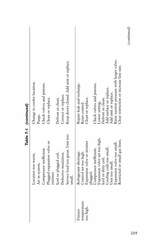
P1: GDZ/FFX P2: GDZ/FFX QC: GDZ/FFX T1: GDZ
GB076-07 GB076-Miller-Sample July 14, 2004 22:27 Char Count= 0
Tabl
e7-
1(c
onti
nued
)
Loc
atio
nto
ow
arm
.C
hang
eto
cool
erlo
cati
on.
Air
insy
stem
.Pu
rge.
Com
pres
sor
inef
ficie
nt.
Che
ckva
lves
and
pist
ons.
Plug
ged
expa
nsio
nva
lve
orre
tain
er.
Cle
anor
repl
ace.
Iced
orpl
ugge
dco
il.D
efro
stor
clea
n.D
efec
tive
insu
lati
on.
Cor
rect
orre
plac
e.Se
rvic
elo
adto
ogr
eat.
Uni
tto
osm
all.
Kee
pdo
ors
clos
ed.A
ddun
itor
repl
ace.
Fixt
ure
tem
pera
ture
too
high
.
Ref
rige
rant
shor
tage
.C
ontr
olse
tto
ohi
gh.
Exp
ansi
onva
lve
orst
rain
erpl
ugge
d.C
ompr
esso
rin
effic
ient
.E
xpan
sion
valv
ese
tto
ohi
gh.
Iced
ordi
rty
coil.
Coo
ling
coils
too
smal
l.U
nit
too
smal
l.E
xpan
sion
valv
eto
osm
all.
Res
tric
ted
orsm
allg
aslin
es.
Rep
air
leak
and
rech
arge
.R
eset
cont
rol.
Cle
anor
repl
ace.
Che
ckva
lves
and
pist
ons.
Low
erse
ttin
g.D
efro
stor
clea
n.A
ddsu
rfac
eor
repl
ace.
Add
unit
orre
plac
e.R
aise
suct
ion
pres
sure
wit
hla
rger
valv
e.C
lear
rest
rict
ion
orin
crea
selin
esi
ze.
(con
tinu
ed)
209

P1: GDZ/FFX P2: GDZ/FFX QC: GDZ/FFX T1: GDZ
GB076-07 GB076-Miller-Sample July 14, 2004 22:27 Char Count= 0
Tabl
e7-
1(c
onti
nued
)
Sym
pto
mP
ossi
ble
Cau
seP
ossi
ble
Rem
edy
Com
pres
sor
star
ts,
but
mot
orw
illno
tge
tof
fst
arti
ngw
indi
ng.
Low
line
volt
age.
Bri
ngup
volt
age.
Impr
oper
lyw
ired
.C
heck
wir
ing
agai
nst
diag
ram
.D
efec
tive
rela
y.C
heck
oper
atio
nm
anua
lly.R
epla
cere
lay
ifde
fect
ive.
Run
ning
capa
cito
rsh
orte
d.C
heck
bydi
scon
nect
ing
runn
ing
capa
cito
r.St
arti
ngan
dru
nnin
gw
indi
ngs
shor
ted.
Che
ckre
sist
ance
.Rep
lace
stat
orif
defe
ctiv
e.
Star
ting
capa
cito
rw
eak.
Che
ckca
paci
tanc
e.R
epla
ceif
low
.H
igh
disc
harg
epr
essu
re.
Che
ckdi
scha
rge
shut
off
valv
e.C
heck
pres
sure
.T
ight
com
pres
sor.
Che
ckoi
llev
el.C
heck
bind
ing.
Com
pres
sor
nois
y.Fo
unda
tion
too
light
,or
loos
efo
unda
tion
bolt
s.C
heck
size
offo
unda
tion
.Che
cksh
im.T
ight
enal
lbol
ts.
Too
muc
hoi
lin
circ
ulat
ion,
caus
ing
hydr
aulic
knoc
ks.
Che
ckoi
llev
el.R
emov
eex
cess
,if
any.
Als
och
eck
for
oila
tre
frig
eran
tte
stco
ck.
Slug
ging
due
toflo
odin
gba
ckof
refr
iger
ant.
Che
ckth
erm
al-b
ulb
loca
tion
and
fast
enin
g.R
eset
expa
nsio
nva
lve.
Tra
psu
ctio
nlin
eso
refr
iger
ant
will
not
flood
back
onth
eof
fcy
cle.
Wor
npa
rts
such
aspi
ston
s,pi
ston
pins
,or
conn
ecti
ngro
ds.
Det
erm
ine
loca
tion
ofca
use.
Rep
air
orre
plac
eco
mpr
esso
r.
Res
tric
tion
inlin
e.B
esu
redi
scha
rge
valv
eis
wid
eop
en,o
rin
stal
lmuf
fler.
Oil
leav
esco
mpr
esso
r.W
etsu
ctio
nca
usin
goi
lfoa
min
g.A
djus
tex
pans
ion
valv
esan
dch
eck
ther
mal
bulb
sfo
rpr
oper
mou
ntin
g.C
heck
refr
iger
ant
pipi
ng.
(con
tinu
ed)
210
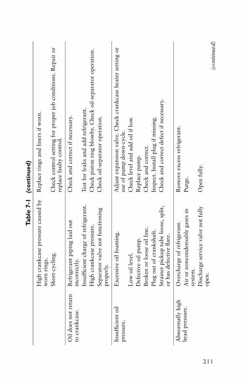
P1: GDZ/FFX P2: GDZ/FFX QC: GDZ/FFX T1: GDZ
GB076-07 GB076-Miller-Sample July 14, 2004 22:27 Char Count= 0
Tabl
e7-
1(c
onti
nued
)
Hig
hcr
ankc
ase
pres
sure
caus
edby
wor
nri
ngs.
Rep
lace
ring
san
dlin
ers
ifw
orn.
Shor
t-cy
clin
g.C
heck
cont
rols
etti
ngfo
rpr
oper
job
cond
itio
ns.R
epai
ror
repl
ace
faul
tyco
ntro
l.
Oil
does
not
retu
rnto
cran
kcas
e.R
efri
gera
ntpi
ping
laid
out
inco
rrec
tly.
Che
ckan
dco
rrec
tif
nece
ssar
y.
Insu
ffici
ent
char
geof
refr
iger
ant.
Test
for
leak
san
dad
dre
frig
eran
t.H
igh
cran
kcas
epr
essu
re.
Che
ckpi
ston
ring
blow
by.C
heck
oil-
sepa
rato
rop
erat
ion.
Sepa
rato
rva
lve
not
func
tion
ing
prop
erly
.C
heck
oil-
sepa
rato
rop
erat
ion.
Insu
ffici
ent
oil
pres
sure
.E
xces
sive
oilf
oam
ing.
Adj
ust
expa
nsio
nva
lve.
Che
ckcr
ankc
ase
heat
erse
ttin
gor
use
ofpu
mp
dow
n-cy
cle.
Low
oill
evel
.C
heck
leve
land
add
oili
flo
w.
Def
ecti
veoi
lpum
p.R
epla
cepu
mp.
Bro
ken
orlo
ose
oill
ine.
Che
ckan
dco
rrec
t.Pl
ugou
tof
cran
ksha
ft.
Insp
ect.
Inst
allp
lug
ifm
issi
ng.
Stra
iner
pick
uptu
belo
ose,
split
,or
has
defe
ctiv
efla
re.
Che
ckan
dco
rrec
tde
fect
ifne
cess
ary.
Abn
orm
ally
high
head
pres
sure
.O
verc
harg
eof
refr
iger
ant.
Rem
ove
exce
ssre
frig
eran
t.A
iror
nonc
onde
nsab
lega
ses
insy
stem
.Pu
rge.
Dis
char
gese
rvic
eva
lve
not
fully
open
.O
pen
fully
.
(con
tinu
ed)
211
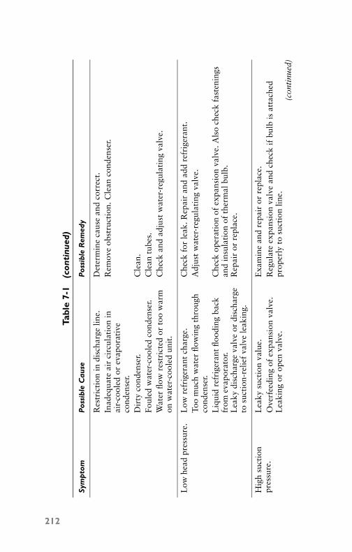
P1: GDZ/FFX P2: GDZ/FFX QC: GDZ/FFX T1: GDZ
GB076-07 GB076-Miller-Sample July 14, 2004 22:27 Char Count= 0
Tabl
e7-
1(c
onti
nued
)
Sym
pto
mP
ossi
ble
Cau
seP
ossi
ble
Rem
edy
Res
tric
tion
indi
scha
rge
line.
Det
erm
ine
caus
ean
dco
rrec
t.In
adeq
uate
air
circ
ulat
ion
inai
r-co
oled
orev
apor
ativ
eco
nden
ser.
Rem
ove
obst
ruct
ion.
Cle
anco
nden
ser.
Dir
tyco
nden
ser.
Cle
an.
Foul
edw
ater
-coo
led
cond
ense
r.C
lean
tube
s.W
ater
flow
rest
rict
edor
too
war
mon
wat
er-c
oole
dun
it.
Che
ckan
dad
just
wat
er-r
egul
atin
gva
lve.
Low
head
pres
sure
.L
owre
frig
eran
tch
arge
.C
heck
for
leak
.Rep
air
and
add
refr
iger
ant.
Too
muc
hw
ater
flow
ing
thro
ugh
cond
ense
r.A
djus
tw
ater
-reg
ulat
ing
valv
e.
Liq
uid
refr
iger
ant
flood
ing
back
from
evap
orat
or.
Che
ckop
erat
ion
ofex
pans
ion
valv
e.A
lso
chec
kfa
sten
ings
and
insu
lati
onof
ther
mal
bulb
.L
eaky
disc
harg
eva
lve
ordi
scha
rge
tosu
ctio
n-re
lief
valv
ele
akin
g.R
epai
ror
repl
ace.
Hig
hsu
ctio
npr
essu
re.
Lea
kysu
ctio
nva
lue.
Exa
min
ean
dre
pair
orre
plac
e.O
verf
eedi
ngof
expa
nsio
nva
lve.
Lea
king
orop
enva
lve.
Reg
ulat
eex
pans
ion
valv
ean
dch
eck
ifbu
lbis
atta
ched
prop
erly
tosu
ctio
nlin
e.(c
onti
nued
)
212

P1: GDZ/FFX P2: GDZ/FFX QC: GDZ/FFX T1: GDZ
GB076-07 GB076-Miller-Sample July 14, 2004 22:27 Char Count= 0
Tabl
e7-
1(c
onti
nued
)
Exc
essi
velo
adon
the
evap
orat
or.
Che
ckai
rin
filtr
atio
nan
din
sula
tion
.L
owsu
ctio
npr
essu
re.
Dir
tysu
ctio
nsc
reen
sor
suct
ion-
stop
valv
epa
rtia
llycl
osed
.C
lean
scre
ens.
Che
cksu
ctio
nva
lve
and
open
wid
e.
Res
tric
tion
inliq
uid-
line
clog
ged
stra
iner
orde
hydr
ator
,etc
.,ca
usin
gliq
uid
tofla
shan
dre
stri
ctflo
w.
Cle
anst
rain
er.C
orre
ctre
stri
ctio
n.
Insu
ffici
ent
refr
iger
ant
insy
stem
.R
epai
rle
akan
dch
arge
.To
om
uch
oilc
ircu
lati
ngin
syst
em,r
educ
ing
heat
tran
sfer
inev
apor
ator
.
Che
ckfo
rex
cess
oili
nsy
stem
.Rem
ove
exce
ssoi
l.
Impr
oper
adju
stm
ent
orex
pans
ion
valv
eto
osm
all.
Adj
ust
valv
e.
Exc
essi
vepr
essu
redr
opth
roug
hev
apor
ator
,wit
hcl
ogge
dex
tern
aleq
ualiz
er.
Be
sure
exte
rnal
equa
lizer
blow
scl
ear
and
not
plug
ged.
Low
head
pres
sure
.C
heck
and
adju
stw
ater
-reg
ulat
ing
valv
e.C
heck
refr
iger
atin
gch
arge
.L
ight
load
onev
apor
ator
.C
heck
capa
city
agai
nst
load
.Red
uce
capa
city
ifne
cess
ary.
Eva
pora
torco
ilfr
oste
d.D
efro
stco
il.
213

P1: GDZ/FFX P2: GDZ/FFX QC: GDZ/FFX T1: GDZ
GB076-07 GB076-Miller-Sample July 14, 2004 22:27 Char Count= 0
214 Chapter 7
After repairs are made, thoroughly clean the parts with gasoline orcarbon tetrachloride, reassemble them (using new gaskets), and re-peat the efficiency test to ensure that the trouble has been eliminated.
CautionCarbon tetrachloride (CCl4) can cause permanent liver damageif the fumes are breathed and can be fatal if proper ventilationis not used.
Troubleshooting GuideThe troubleshooting guide provided in Table 7-1 will assist in ser-vicing air-conditioning systems. It should be noted, however, that al-though the trouble may differ at times from that given in Table 7-1,experience will usually quickly reveal the exact cause, after whichthe remedy and its correction may be carried out.
SummaryThe mechanical components of a gas-compression refrigeration sys-tem include the compressor, condenser, receiver, evaporator, and var-ious types of refrigerant controls.
Compressors come in various sizes. They are classified accordingto their methods of operation. Methods of operation may be recip-rocating, rotary, or centrifugal. The function of a compressor is toprovide the necessary pumping action to remove the refrigerant gasfrom the evaporator, compress the gas, and finally discharge it intothe condenser, where it is liquefied.
The condenser causes the heat picked up from the evaporator bythe refrigerant to be discharged to the air outside the refrigeratedarea. Air-cooled condensers are most commonly used for home airconditioners.
Receivers are reservoirs for excess liquid refrigerant not beingused in the system. The evaporator is that part of the system wherethe useful cooling is accomplished by removing the heat from thearea to be cooled.
Refrigerant controls are devices that furnish the needed on-offoperations for taking the refrigerant from one part of the system tothe other at the proper time to produce the removal of heat from arefrigerated space.
The cycle of operation that is the cooling process consists of fourseparate steps. In the vaporizing process, the low-temperature, low-pressure refrigerant in the evaporator absorbs heat from the mate-rial or space being refrigerated and is transformed from a liquid to

P1: GDZ/FFX P2: GDZ/FFX QC: GDZ/FFX T1: GDZ
GB076-07 GB076-Miller-Sample July 14, 2004 22:27 Char Count= 0
Compressors for Air Conditioners 215
a vapor in the process. The compression process takes place whenthe compressor draws the heat-laden vapor from the evaporatorthrough the return piping and compresses this vapor until the tem-perature is above that of the condensing medium.
The other two parts of the cooling process are the condensingprocess and the pressure-reducing process. In the compressor, thetemperature of the refrigerant has been raised above that of the con-densing medium (usually 15◦F to 25◦F). The heat of vaporizationwill flow from the vapor to the condensing medium and condensethe refrigerant to a high-pressure liquid. This high-pressure liquidthen flows to the receiver, where it is stored until it is supplied to thecooling unit through the expansion valve.
As the compressor withdraws the refrigerant vapor from theevaporator, the cooling unit must be supplied with more low-temperature, low-pressure refrigerant capable of absorbing heat. Aconstant flow of liquid is maintained to the evaporator, where it va-porizes and takes the heat of the area back to the compressor againto repeat the cycle.
Compressors can be categorized as either single- or multicylinderwith respect to operation. However, according to the method ofcompression used, they are classified as reciprocating, rotary, orcentrifugal. With respect to drive, the compressors are classified asdirect drive or belt drive. They may also be classified or groupedwith respect to their prime mover. Under this classification, theyare independent (belt drive), semi-hermetic (direct-drive with motorand compressor in separate housings), or hermetic (direct-drive withmotor and compressor in the same housing).
Review Questions1. What are the components needed for the operation of a gas-
compression refrigeration system?2. How are compressors classified according to methods of op-
eration?3. What is the difference between a compressor and a condenser?4. What is the function of an evaporator?5. Where is the receiver located in the refrigeration system?6. Why does the condenser usually need a fan?7. What does hermetic mean?8. Describe a shaft seal for a compressor.9. How does the rotary compressor operate?

P1: GDZ/FFX P2: GDZ/FFX QC: GDZ/FFX T1: GDZ
GB076-07 GB076-Miller-Sample July 14, 2004 22:27 Char Count= 0
216 Chapter 7
10. How is the centrifugal compressor different from the rotarycompressor?
11. What may be the cause (or causes) of a knock in a compressor?12. What is the usual reason for a compressor being stuck-up?13. How do you find compressor efficiency?14. What would you do to repair an air conditioner if the fan on
the evaporator doesn’t run and the compressor short-cycles?15. What are the possible causes for the running cycle of an air
conditioner being too long?

P1: GDZ/FFX P2: GDZ/FFX QC: GDZ/FFX T1: GDZ
GB076-08 GB076-Miller-Sample July 15, 2004 16:32 Char Count= 0
Chapter 8Condensing Equipment forAir ConditionersThe function of a condenser in a mechanical refrigeration system isto liquefy the refrigerant gas and return it (by means of controls) fora repeat of the refrigeration cycle. When the refrigerant gas leavesthe compressor and enters the condenser, it contains the full load ofheat, consisting of the following:
� The heat picked up in the evaporator as net refrigeration� The heat of cooling the liquid from the condenser to the evap-
orating temperature� The heat picked up in the suction line and cylinder chamber� The heat of compression
Condensers may be classified according to their construction asfollows:
� Air-cooled� Water-cooled� Evaporative (combination of air and water)
Air-Cooled CondensersAir-cooled condensers are used universally on smaller refrigeratingunits, but seldom for capacities in excess of 3 tons of refrigeration.They are equipped for natural draft and fan cooling and are termedaccording to their construction as plain tubes, finned tubes, platetype, and series or parallel pass. The conventional air-cooled con-denser consists of an extended-surface coil across which air is blownby a fan. In operation, hot discharge gas enters the coil at the top. Asit is condensed, it flows to a receiver located below the condenser.Figure 8-1 and Figure 8-2 show typical air-cooled condensing units.
Air-cooled condensers should always be located in a well-ventilated space. This is how the heated air may escape and bereplaced by cooled air. Because of space requirements, air-cooledcondensers are normally constructed with a relatively small facewith several rows of tubing in depth. As the air is forced throughthe condenser, it absorbs heat, and the air temperature rises. There-fore, the efficiency of each succeeding row in the coil decreases,although coils up to eight rows in depth are frequently used.
217
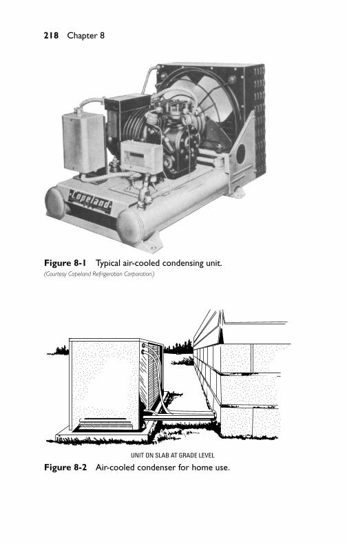
P1: GDZ/FFX P2: GDZ/FFX QC: GDZ/FFX T1: GDZ
GB076-08 GB076-Miller-Sample July 15, 2004 16:32 Char Count= 0
218 Chapter 8
Figure 8-1 Typical air-cooled condensing unit.(Courtesy Copeland Refrigeration Corporation.)
UNIT ON SLAB AT GRADE LEVEL
Figure 8-2 Air-cooled condenser for home use.

P1: GDZ/FFX P2: GDZ/FFX QC: GDZ/FFX T1: GDZ
GB076-08 GB076-Miller-Sample July 15, 2004 16:32 Char Count= 0
Condensing Equipment for Air Conditioners 219
Water-Cooled CondensersUsed on commercial and larger systems, water-cooled condensersare classified as double-pipe, flooded atmospheric; bleeder shell-and-tube, and shell-and-coil. In condensers of this type, the amountand temperature of the water determine the condensing tempera-ture and pressure, and (indirectly) the power required for compres-sion. In locations where water must be conserved or where water isrestricted, it is usually necessary to install cooling towers or evap-orative condensers. When adequate low-cost condensing water isavailable, water-cooled condensers are often desirable because ofthe lower condensing pressures and better head-pressure control.
Water (particularly from underground sources) may be muchcolder than daytime temperatures. If evaporative cooling towersare used, the condensing water can be cooled to a point closelyapproaching the ambient wet-bulb temperature, which allows thecontinuous recirculation of condensing water and reduces waterconsumption to a minimum. A water-cooled condensing unit isshown in Figure 8-3.
Figure 8-3 Typical water-cooled condensing unit.(Courtesy Copeland Refrigeration Corporation.)
A pressure- or temperature-sensitive modulating water-controlvalve (such as shown in Figure 8-4) can be used to maintain condens-ing pressures within the desired range by increasing or decreasingthe rate of water flow as necessary.

P1: GDZ/FFX P2: GDZ/FFX QC: GDZ/FFX T1: GDZ
GB076-08 GB076-Miller-Sample July 15, 2004 16:32 Char Count= 0
220 Chapter 8
Figure 8-4 Temperature-actuated,water-regulating valve as employed onwater-cooled condensers.(Courtesy Penn Controls, Inc.)
Cooling-Water CircuitsIn compressors with water jackets and in water-cooled condensers,cooling-water circuits may be in series or parallel. The use of parallelcircuits results in a lower pressure drop through the circuit, and maybe necessary when the temperature of the cooling water is such thatthe water temperature rise must be held to a minimum. Figure 8-5and Figure 8-6 show how to install water lines for series or parallelflow.
Because of occasional damage to condensers by excessive watervelocities, it has been found that the water velocity should not exceed7 feet per second. Thus, to maintain water velocities at acceptablelevels, parallel circuiting of the condenser may be necessary. Whena water-circulating pump is used, it should be installed so that thecondenser is fed from the discharge side of the pump. If the pump isinstalled on the discharge side of the condenser, the condenser willhave a slight vacuum in the water system and the water will be muchnearer the boiling point.
Types of Water-Cooled CondensersThe three types of water-cooled condensers are the double-tube, theshell-and-coil, and the shell-and-tube types.
Double TubeThe double-tube condenser type consists of two tubes, one insidethe other (see Figure 8-7). Water is piped through the inner tube,
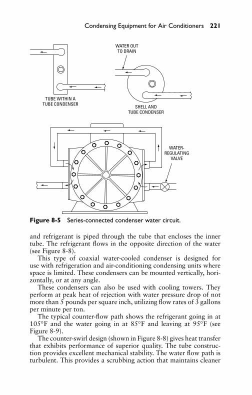
P1: GDZ/FFX P2: GDZ/FFX QC: GDZ/FFX T1: GDZ
GB076-08 GB076-Miller-Sample July 15, 2004 16:32 Char Count= 0
Condensing Equipment for Air Conditioners 221
WATER-REGULATING
VALVE
TUBE WITHIN ATUBE CONDENSER SHELL AND
TUBE CONDENSER
WATER OUTTO DRAIN
Figure 8-5 Series-connected condenser water circuit.
and refrigerant is piped through the tube that encloses the innertube. The refrigerant flows in the opposite direction of the water(see Figure 8-8).
This type of coaxial water-cooled condenser is designed foruse with refrigeration and air-conditioning condensing units wherespace is limited. These condensers can be mounted vertically, hori-zontally, or at any angle.
These condensers can also be used with cooling towers. Theyperform at peak heat of rejection with water pressure drop of notmore than 5 pounds per square inch, utilizing flow rates of 3 gallonsper minute per ton.
The typical counter-flow path shows the refrigerant going in at105◦F and the water going in at 85◦F and leaving at 95◦F (seeFigure 8-9).
The counter-swirl design (shown in Figure 8-8) gives heat transferthat exhibits performance of superior quality. The tube construc-tion provides excellent mechanical stability. The water flow path isturbulent. This provides a scrubbing action that maintains cleaner

P1: GDZ/FFX P2: GDZ/FFX QC: GDZ/FFX T1: GDZ
GB076-08 GB076-Miller-Sample July 15, 2004 16:32 Char Count= 0
222 Chapter 8
TUBE WITHIN ATUBE CONDENSER
SHELL ANDTUBE CONDENSER
WATER OUTTO DRAIN
Figure 8-6 Parallel-connected condenser water circuit.
Figure 8-7 Coaxial water-cooled condenser. It is used with refrigera-tion and air-conditioning units where space is limited.

P1: GDZ/FFX P2: GDZ/FFX QC: GDZ/FFX T1: GDZ
GB076-08 GB076-Miller-Sample July 15, 2004 16:32 Char Count= 0
Condensing Equipment for Air Conditioners 223
WATER
WATER
REFRIGERANT
REFR
IGER
ANT
REFR
IGER
ANT
Figure 8-8 Typical counter-flow path inside a coaxial water-cooledcondenser.
REFRIGERANT
105°F
105°F [41°C] 95°F [35°C] 85°F [29°C]
95°F 85°F
WATER
Figure 8-9 Water andrefrigerant temperatures in acounter-flow, water-cooledcondenser.
surfaces. The construction method shown also has very high systempressure resistance.
The water-cooled condenser shown in Figure 8-7 can be obtainedin a number of combinations. Some of these combinations are listedin Table 8-1. Copper tubing is suggested for use with fresh waterand with cooling towers. The use of cupronickel is suggested whensalt water is used for cooling purposes.
Table 8-1 Possible Metal Combinations inWater-Cooled Condensers
Shell Metal Tubing Metal
Steel CopperCopper CopperSteel CupronickelCopper CupronickelSteel Stainless steelStainless steel Stainless steel

P1: GDZ/FFX P2: GDZ/FFX QC: GDZ/FFX T1: GDZ
GB076-08 GB076-Miller-Sample July 15, 2004 16:32 Char Count= 0
224 Chapter 8
Convolutions in the water tube result in a spinning, swirling waterflow that inhibits the accumulation of deposits on the inside of thetube. This contributes to the antifouling characteristics in this typeof condenser. Figure 8-10 shows the various types of constructionfor the condenser. This type of condenser may be added as a boosterto standard air-cooled units.
(A) Single lead. (B) Double lead. (C) Triple lead.
Figure 8-10 Different types of tubing fabrication inside the coaxialwater-cooled condenser.
Figure 8-11 shows some of the configurations of this type ofcondenser: the spiral, the helix, and the trombone. Note the inputfor the water and input for the refrigerant. The condensers can befurther cooled by using a cooling tower to furnish water to contactthe outside tube. A water tower can be used to cool the water sentthrough the inside tube for cooling purposes. This type of condenseris usable where refrigeration or air-conditioning requirements are1/3 ton up to 3 tons.
Shell-and-Coil CondensersThe shell-and-coil condenser is made by placing a bare tube ora finned tube inside a steel shell (Figure 8-12). Water circulatesthrough the coils. Refrigerant vapor is injected into the shell. Thehot vapor contacts the cooler tubes and condenses. The condensedvapor drains from the coils and drops to the bottom of the tankor shell. There it is recirculated through the refrigerated areas byway of the evaporator. In most cases, the unit is cleaned by placingchemicals into the water. The chemicals have a tendency to removedeposits that build up on the tubing walls.
Evaporative CondensersEvaporative condensers are essentially a combination of a watertower and a water-cooled condenser in which the condenser is placedin intimate contact with the air and water spray. In condensers of
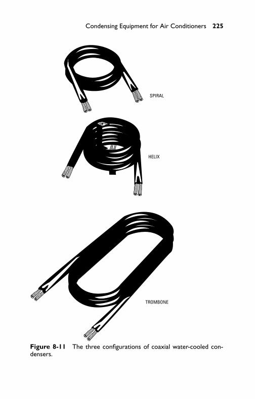
P1: GDZ/FFX P2: GDZ/FFX QC: GDZ/FFX T1: GDZ
GB076-08 GB076-Miller-Sample July 15, 2004 16:32 Char Count= 0
Condensing Equipment for Air Conditioners 225
SPIRAL
HELIX
TROMBONE
Figure 8-11 The three configurations of coaxial water-cooled con-densers.

P1: GDZ/FFX P2: GDZ/FFX QC: GDZ/FFX T1: GDZ
GB076-08 GB076-Miller-Sample July 15, 2004 16:32 Char Count= 0
226 Chapter 8
SHELLCOILS
WATER OUT
WATER IN
LIQUIDREFRIGERANTOUT
REFRIGERANTVAPOR IN
Figure 8-12 The shell-and-coil condenser. This is a series type of coilarrangement inside the shell, which the refrigerant enters as a vapor andleaves as a liquid.
this type, the heat in the refrigerant gas is carried away by the air, thecirculating water acting merely as an agent in the heat transfer. Theeffectiveness of any evaporative condenser, however, is dependenton the wet-bulb temperature of the air entering the unit since thisdetermines the minimum temperature to which the spray water canbe cooled. Condensers of the evaporative types are manufactured insizes up to 100 tons or more.
In the operation of a typical evaporative condenser (see Figure8-13), the circulating pump draws water from the water pan anddischarges it above the condensing coils through a series of spraynozzles. The spray nozzles are arranged to distribute the water uni-formly over the condensing coil. A large excess of water is circulatedby the pump to keep the coil surface clean and maintain the rate ofheat transfer. Makeup water is supplied to provide an overflow forthe removal of dirt, prevent excessive deposition of lime on the con-densing coil surfaces, and reduce the acidity of the recirculated water.
Centrifugal fans draw rated quantities of air through the con-densing coils and water spray where the relative humidity greatlyincreases. The air is then passed through water-eliminator plates and

P1: GDZ/FFX P2: GDZ/FFX QC: GDZ/FFX T1: GDZ
GB076-08 GB076-Miller-Sample July 15, 2004 16:32 Char Count= 0
Condensing Equipment for Air Conditioners 227
WATERELIMINATORS
NONMETALLICHEADER
AND SPRAYS
WATERNOZZLES
MOLDEDFIBERGLASS
FLOATMAKE-UP
WATER
MOTOR
BLOWER
PRIME TUBECOIL
HEAVY-GAGE,EPOXY-COATEDSTEEL CASING
MOLDEDFIBERGLASSDRAINPAN
MOLDEDFIBERGLASS
DAMPER(CLOSED—FAN OFF)
MOLDEDFIBERGLASS
DAMPER(OPEN—FAN ON)
CAPACITYMODULATOR
(THERMOSTATICALLYCONTROLLED)
OPTIONAL
SPRAY(PUMP AND PIPING
FURNISHED INSTALLED)
Figure 8-13 Schematic view of an evaporative condenser.(Courtesy Dunham-Bush, Inc.)
discharged to the outside in such a manner as to ensure that it willnot be recirculated. The hot refrigerant gas enters the condensingcoils through a manifold, which ensures a low-pressure drop. Thegas is condensed to a liquid in the coils, which are arranged to givea counter flow passage of refrigerant and air. The liquid flows fromthe condenser to a receiver (or receivers) located in the water reser-voir, where it is held in storage for use in the evaporator section ofthe system.

P1: GDZ/FFX P2: GDZ/FFX QC: GDZ/FFX T1: GDZ
GB076-08 GB076-Miller-Sample July 15, 2004 16:32 Char Count= 0
228 Chapter 8
Head-Pressure Control MethodsIn application of refrigeration condensers, it is a good idea to takeadvantage of lower-than-design condensing temperatures wheneverpossible to achieve the effects of more refrigeration capacity fromthe system, lower brake-horsepower requirements per ton of re-frigeration, and lower compressor discharge temperatures. At thesame time, it is often necessary to take precautions so that the con-densing pressure does not drop down too low during periods oflow-water temperatures or low outside air temperatures. This isparticularly true on installations that have high internal or processloads throughout the year and on systems having compressor ca-pacity control.
The principal problem arising from abnormally low condensingpressures is the reduction of the pressure difference available acrossthe expansion valve to the point where it is unable to feed sufficientrefrigerant to the evaporator to handle the cooling load. Liquid feeddevices are rated in accordance with the pressure difference acrossthe port. A valve selected at a pressure difference of 60 lb, whichis the standard rating point for Freon-12 valves, would have sub-stantially less capacity if the pressure difference available were only20 lb. Common types of head-pressure control arrangements areused, which are considered in relation to the various types of con-densers used.
Water-Cooled CondensersWith water-cooled condensers, head-pressure controls are used forthe dual purpose of holding the condensing pressure up and con-serving water. On cooling-tower applications, they are used onlywhere it is necessary to hold condensing temperatures up.
The control commonly used with water-cooled condensers is thecondenser water-regulating valve. This valve is usually located in thewater supply line to the condenser. It is a throttling-type valve andresponds to a difference between condensing pressure and a prede-termined shutoff pressure. Figure 8-14 shows a typical water-cooledcondenser. The higher this difference, the more the valve opens up,and vice versa. A pilot connection to the top of the condenser trans-mits condensing pressure to the valve, which assumes an openingposition according to this pressure.
The shutoff pressure of the valve must be set slightly higher thanthe highest refrigerant pressure expected in the condenser when thesystem is not in operation. This is to make sure the valve will closeand not pass water during off cycles. This pressure will be slightlyhigher than the saturation pressure of the refrigerant at the highestambient temperature expected around the condenser.

P1: GDZ/FFX P2: GDZ/FFX QC: GDZ/FFX T1: GDZ
GB076-08 GB076-Miller-Sample July 15, 2004 16:32 Char Count= 0
Condensing Equipment for Air Conditioners 229
SEAMLESS STEEL SHELL
Figure 8-14 Exterior view of a shell-and-tube, water-cooled con-denser. (Courtesy Westinghouse Electric Corp.)
Condenser water-regulating valves are usually sized to pass thedesign quantity of water at about a 25- to 30-lb difference betweendesign condensing pressure and valve shutoff pressure. In coolingtower applications, a simple bypass can also be used to maintaincondensing temperature by employing a manual valve or an auto-matic valve responsive to head-pressure change. The valve can beeither the two- or three-way type.
Evaporative CondensersWhen installed outdoors, this type of unit should be located so thatthere is a free flow of air. A minimum clearance of twice the width ofthe unit should be provided at the air inlet and outlet. Care shouldbe taken that the flow of the discharge air is not deflected backto the inlet. Short-circuiting in this fashion can materially reducethe cooling capacity. Special consideration should be given to short-circuiting on multiple installations.
It is very desirable to position the unit so that the prevailing sum-mer wind will blow into the inlet. It is also desirable to take pre-cautions against a strong wind blowing into the outlet, which canreduce the capacity and might overload the fan motor. A windbreakerected about 6 feet from the air discharge is often useful in pre-venting this. In some outdoor locations, it may be desirable to placea coarse screen over the air inlet to exclude large objects (such asbirds, paper, and other debris). Although towers and evaporativecondensers are exceptionally quiet in operation, it is still good prac-tice to locate the units as far as possible from other air intake hoodswhere air and water sounds might be transmitted into offices orliving spaces.
If the unit is installed indoors, careful consideration must be givento supplying and removing an adequate amount of air from thespace. If the discharge air is allowed to recirculate, the wet-bulb

P1: GDZ/FFX P2: GDZ/FFX QC: GDZ/FFX T1: GDZ
GB076-08 GB076-Miller-Sample July 15, 2004 16:32 Char Count= 0
230 Chapter 8
temperature will rise and the capacity will be reduced. It is usu-ally possible to omit a duct to the air inlet. The unit can draw airfrom the room, but provision should be made to supply an ad-equate amount of replacement fresh air. Blower-type units may beconnected to ducts giving an external static pressure of up to 1/4 inchof water.
The piping to and from the unit should be installed in accordancewith good practice, using pipe sizes at least as large as the fittingson the unit. It is desirable to use vibration eliminators on all lines toand from units. The units should be installed so that the top covercan be lifted for maintenance. The makeup water line should beconnected to the float valve. If it is desired to use the makeup line tofill the system, it may be desirable to make the pipe size larger thanthe float-valve connection size. In some locations, it is permissibleto let the overflow drain on the roof. However, if this is not desired,the overflow should be piped to the sewer. A bleed or blow-downconnection should be incorporated in the piping. This should beinstalled in the pump discharge pipe at a high enough level so thatthe bleed flows only when the pump is operating.
It is convenient to have a hose bib available near the unit foruse in periodic washing down and cleaning of the case and sump.If the unit is installed outdoors and must operate in winter, theinstallation should be made using an indoor storage tank in a heatedspace. Figure 8-15 shows a recommended piping arrangement forevaporative condensers. The pump should be moved indoors andconnected to the outlet of the indoor storage tank.
Air-Cooled CondensersWith air-cooled condensers, various methods employed forcondensing-pressure control are cycling fan motor, air-throttlingdamper, and coil flooding. The first two methods are described in theprevious section, Evaporative Condensers. The third method holdsthe condensing temperature up by reducing condenser capacity. Thisis achieved by backing liquid refrigerant up in the coil to cut downon the effective condensing surface.
The basic principle of the pressure stabilizer (see Figure 8-16)consists of a heat-transfer device, which transfers the heat from thehot-gas discharge of the compressor to the subcooled liquid leavingthe condenser. This heat exchange is controlled by the regulatingvalve installed between the condenser and the receiver. This valve isset at the desired operating pressure and throttles from the open posi-tion to the closed position as the head pressure drops. The throttlingaction of the valve forces liquid to flow through the heat-exchanger

P1: GDZ/FFX P2: GDZ/FFX QC: GDZ/FFX T1: GDZ
GB076-08 GB076-Miller-Sample July 15, 2004 16:32 Char Count= 0
Condensing Equipment for Air Conditioners 231
PUMP
INDOOR SUMP
ROOF
DRAIN
CAPPEDOUTLET
OVER-FLOW
CAPPED WATERMAKE-UP
DUAL DRY EVAPORATIVE CONDENSER
DRAIN OUTLETTO SEWER
OVERFLOW AND BLEED
WATER MAKE-UP
Figure 8-15 Schematic diagram of piping arrangement for an evapo-rative condenser.
LIQUID LINE FROMCOMPRESSOR
DISCHARGE LINE
HOT-GAS HEADERSECONDARY CHECK
VALVECHECK VALVE
RECEIVER
18”
PRESSURESTABILIZER
Figure 8-16 Piping arrangement showing pressure-stabilizing methodfor an air-cooled condenser.
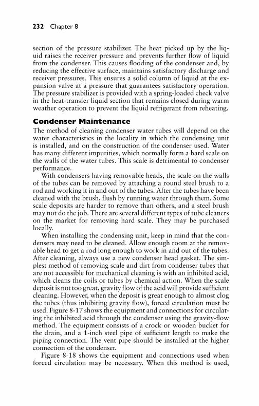
P1: GDZ/FFX P2: GDZ/FFX QC: GDZ/FFX T1: GDZ
GB076-08 GB076-Miller-Sample July 15, 2004 16:32 Char Count= 0
232 Chapter 8
section of the pressure stabilizer. The heat picked up by the liq-uid raises the receiver pressure and prevents further flow of liquidfrom the condenser. This causes flooding of the condenser and, byreducing the effective surface, maintains satisfactory discharge andreceiver pressures. This ensures a solid column of liquid at the ex-pansion valve at a pressure that guarantees satisfactory operation.The pressure stabilizer is provided with a spring-loaded check valvein the heat-transfer liquid section that remains closed during warmweather operation to prevent the liquid refrigerant from reheating.
Condenser MaintenanceThe method of cleaning condenser water tubes will depend on thewater characteristics in the locality in which the condensing unitis installed, and on the construction of the condenser used. Waterhas many different impurities, which normally form a hard scale onthe walls of the water tubes. This scale is detrimental to condenserperformance.
With condensers having removable heads, the scale on the wallsof the tubes can be removed by attaching a round steel brush to arod and working it in and out of the tubes. After the tubes have beencleaned with the brush, flush by running water through them. Somescale deposits are harder to remove than others, and a steel brushmay not do the job. There are several different types of tube cleanerson the market for removing hard scale. They may be purchasedlocally.
When installing the condensing unit, keep in mind that the con-densers may need to be cleaned. Allow enough room at the remov-able head to get a rod long enough to work in and out of the tubes.After cleaning, always use a new condenser head gasket. The sim-plest method of removing scale and dirt from condenser tubes thatare not accessible for mechanical cleaning is with an inhibited acid,which cleans the coils or tubes by chemical action. When the scaledeposit is not too great, gravity flow of the acid will provide sufficientcleaning. However, when the deposit is great enough to almost clogthe tubes (thus inhibiting gravity flow), forced circulation must beused. Figure 8-17 shows the equipment and connections for circulat-ing the inhibited acid through the condenser using the gravity-flowmethod. The equipment consists of a crock or wooden bucket forthe drain, and a 1-inch steel pipe of sufficient length to make thepiping connection. The vent pipe should be installed at the higherconnection of the condenser.
Figure 8-18 shows the equipment and connections used whenforced circulation may be necessary. When this method is used,

P1: GDZ/FFX P2: GDZ/FFX QC: GDZ/FFX T1: GDZ
GB076-08 GB076-Miller-Sample July 15, 2004 16:32 Char Count= 0
Condensing Equipment for Air Conditioners 233
CROCK OR WOODEN BUCKET
CROCK OR WOODEN BUCKET
FUNNEL
VENT PIPE
CONDENSER
3 TO 4 FT
Figure 8-17 Condenser cleaning method using gravity circulation.
a suitable pump will be required to provide pressure. The inhibitedsolution is stored in a metal tank (not galvanized) with ordinarybronze or copper fly screening to prevent the large pieces of scale ordirt from getting into the pump intake line. In addition, 1-inch steelpiping with connections and globe valves are provided, as shown.The vent pipe should be installed at the higher connection of thecondenser.
Cleaning PrecautionsWhen handling the inhibited acid for cleaning condensers, certainprecautions will be necessary. The solution will stain the hands andclothing and attack concrete. Hence, every precaution should be
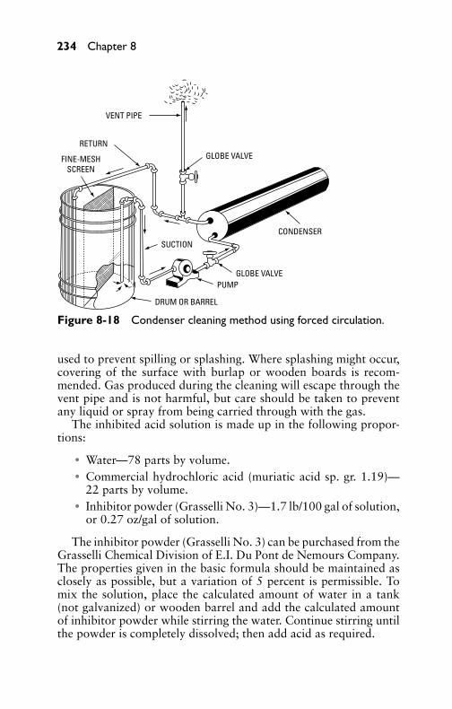
P1: GDZ/FFX P2: GDZ/FFX QC: GDZ/FFX T1: GDZ
GB076-08 GB076-Miller-Sample July 15, 2004 16:32 Char Count= 0
234 Chapter 8
VENT PIPE
GLOBE VALVE
CONDENSER
GLOBE VALVEPUMP
SUCTION
DRUM OR BARREL
RETURN
FINE-MESHSCREEN
Figure 8-18 Condenser cleaning method using forced circulation.
used to prevent spilling or splashing. Where splashing might occur,covering of the surface with burlap or wooden boards is recom-mended. Gas produced during the cleaning will escape through thevent pipe and is not harmful, but care should be taken to preventany liquid or spray from being carried through with the gas.
The inhibited acid solution is made up in the following propor-tions:
� Water—78 parts by volume.� Commercial hydrochloric acid (muriatic acid sp. gr. 1.19)—
22 parts by volume.� Inhibitor powder (Grasselli No. 3)—1.7 lb/100 gal of solution,
or 0.27 oz/gal of solution.
The inhibitor powder (Grasselli No. 3) can be purchased from theGrasselli Chemical Division of E.I. Du Pont de Nemours Company.The properties given in the basic formula should be maintained asclosely as possible, but a variation of 5 percent is permissible. Tomix the solution, place the calculated amount of water in a tank(not galvanized) or wooden barrel and add the calculated amountof inhibitor powder while stirring the water. Continue stirring untilthe powder is completely dissolved; then add acid as required.

P1: GDZ/FFX P2: GDZ/FFX QC: GDZ/FFX T1: GDZ
GB076-08 GB076-Miller-Sample July 15, 2004 16:32 Char Count= 0
Condensing Equipment for Air Conditioners 235
Charging the SystemWhen gravity flow is used, introduce the inhibited acid as shown inFigure 8-17. Do not add the solution faster than the vent can exhaustthe gases that are generated during the cleaning. When the condenserhas been filled, allow the solution to remain there overnight.
When forced circulation is used, the valve in the vent pipe shouldbe fully opened while the solution is being introduced into the con-denser, but must be closed when the condenser is completely chargedand the solution is being circulated by the pump. The valve in thesupply line may be fully closed while the pump (if a centrifugal type)is running should it be required.
Cleaning TimeFor cleaning out the average scale deposit, the solution should beallowed to stand or be circulated in the system overnight. For ex-tremely heavy deposits, forced circulation is recommended, and thetime should be increased to 24 hours. The solution acts more rapidlyif it is warm, but the cleaning action will be just as thorough with acold solution if adequate time is allowed.
Flushing the SystemAfter the solution has been allowed to stand or has been circu-lated through the condenser the required length of time, it shouldbe drained out and the condenser thoroughly flushed with water. Ifit is desired to clean condensers with removable heads with inhib-ited acid, the previous procedure can be used without removing theheads. However, extra precaution must be exercised in flushing outsuch condensers with clear water after the acid has been circulatedthrough the condenser.
Cleaning Evaporative CondensersThe method used in protecting the coils in evaporative condensersfrom scale and other deposits and removing the deposits after theyhave formed depends on the characteristics of the water in the par-ticular location. If the water at the installation site is very hard,solids will form between the coil fins. The first step to take for theprevention of this scale formation is to provide ample overflow. Thisminimizes the concentration of solids in the water and prevents theformation of slime. If the water composition is such that scale willform readily, the water should be chemically treated. For this treat-ment, a sample of the water should be sent to a competent water-treatment organization that will make a complete analysis and willrecommend the proper chemical solution to use.

P1: GDZ/FFX P2: GDZ/FFX QC: GDZ/FFX T1: GDZ
GB076-08 GB076-Miller-Sample July 15, 2004 16:32 Char Count= 0
236 Chapter 8
Removing Scale FormationThe simplest method of removing scale from condenser coils is withan inhibited acid, which cleans the fins and tubes by chemical action.The method of injecting the chemical into the water and the amountto be used will vary. It is suggested that the recommendations ofthe firm supplying the chemical be followed. Figure 8-19 showsconnections and equipment necessary for cleaning the coils with aninhibited acid: one when the acid is used by the hand or gravitymethod, the other when forced circulation is used.
4-PIPE CLAMPSCONDENSER
COIL
DRUMOR BARREL
HOSE
GLOBE VALVE
PUMP
FINE-MESHSCREEN
TEMPORARYDRAIN
Figure 8-19 Cleaning evaporative condenser using forced circulation.
Gravity and Forced CirculationWhen the scale deposit is not very great, gravity or hand cleaningwith the acid will be sufficient; but when the deposit is heavy enoughto block off the space between the fins, then forced circulation shouldbe used. The gravity-flow and forced-circulation methods of remov-ing scale deposits shown in Figure 8-19 and Figure 8-20 do not differgreatly from that given previously with respect to water-cooled con-densers. The basic formula in making up the inhibited-acid solution,the mixing method, and the precautions in handling are identical.
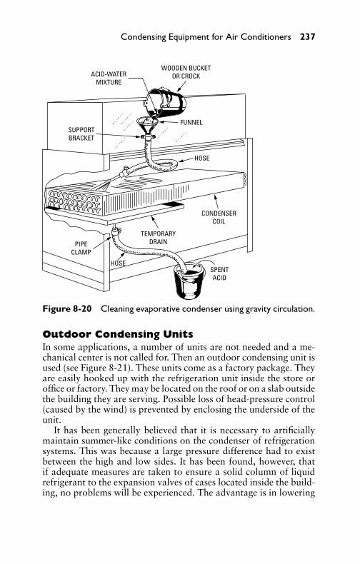
P1: GDZ/FFX P2: GDZ/FFX QC: GDZ/FFX T1: GDZ
GB076-08 GB076-Miller-Sample July 15, 2004 16:32 Char Count= 0
Condensing Equipment for Air Conditioners 237
ACID-WATERMIXTURE
WOODEN BUCKETOR CROCK
FUNNEL
HOSE
HOSE
PIPECLAMP
SUPPORTBRACKET
CONDENSERCOIL
SPENTACID
TEMPORARYDRAIN
Figure 8-20 Cleaning evaporative condenser using gravity circulation.
Outdoor Condensing UnitsIn some applications, a number of units are not needed and a me-chanical center is not called for. Then an outdoor condensing unit isused (see Figure 8-21). These units come as a factory package. Theyare easily hooked up with the refrigeration unit inside the store oroffice or factory. They may be located on the roof or on a slab outsidethe building they are serving. Possible loss of head-pressure control(caused by the wind) is prevented by enclosing the underside of theunit.
It has been generally believed that it is necessary to artificiallymaintain summer-like conditions on the condenser of refrigerationsystems. This was because a large pressure difference had to existbetween the high and low sides. It has been found, however, thatif adequate measures are taken to ensure a solid column of liquidrefrigerant to the expansion valves of cases located inside the build-ing, no problems will be experienced. The advantage is in lowering

P1: GDZ/FFX P2: GDZ/FFX QC: GDZ/FFX T1: GDZ
GB076-08 GB076-Miller-Sample July 15, 2004 16:32 Char Count= 0
238 Chapter 8
TANK HEATER with THERMOSTAT regulates receiver tank temperature between 70 and 100°F. [21 and 38°C].
DUAL PRESSURE CONTROL protects unit from high head pressure, shuts unit down after pump down. Case temperatures are controlled by EPR or TPR valves at cases.
FIXED LOUVERS on exhaust side of unit protect the unit from wind and rain.
LIQUID LINE SOLENOID VALVE—normally closed. It opens only during the refrigeration cycle.
CHECK VALVE holds refrigerant in receiver when the unit is pumped down during defrost or off-cycle.
SUCTION LINE—Ideally, it will be insulated for summertime efficiency and wintertime protection.
CRANK CASE HEATER against or in the compressor crankcase reduces refrigerant migration to the oil.
CLOSE-OFF on bottom of entire unit protects unit from wind and possible loss of head pressure control.
FIXED HOOD protects unit from wind. Head pressure–operated automatic louvers are optionally available.
OIL-PRESSURE SAFETY SWITCH shuts down unit if compressor lubrication system fails. It is manually reset.
SOLID-STATE FAN SPEED CONTROL regulates head pressure by modulating the speed of the fans or by stopping them entirely. Senses gas temperature at top of condenser.
INSULATED RECEIVER TANK holds a pump-down charge during defrost. Insulation prevents rapid heat loss.
Figure 8-21 Outdoor condensing unit with a weather hood.
the condenser temperature. This makes the compressor run moreefficiently, saving on energy costs.
Liquid lines exposed to temperatures above 60◦F (15.6◦C) mustbe insulated. This also applies to any lines that run overhead and tosome lines close to the floor.
SummaryThe function of a condenser in a mechanical refrigeration system isto liquefy the refrigerant gas and return it (by means of controls) fora repeat of the refrigeration cycle. Condensers are classified accord-ing to their construction as air-cooled, water-cooled, or evaporative(a combination of air and water).
Water-cooled condensers use head-pressure controls for the dualpurpose of holding the condensing pressure up and conserving wa-ter. On cooling-tower applications, they are used only where it isnecessary to hold condensing temperatures up.

P1: GDZ/FFX P2: GDZ/FFX QC: GDZ/FFX T1: GDZ
GB076-08 GB076-Miller-Sample July 15, 2004 16:32 Char Count= 0
Condensing Equipment for Air Conditioners 239
Evaporative condensers are essentially a combination of a watertower and a water-cooled condenser in which the condenser is placedin intimate contact with the air and water spray. Condensers of theevaporative types are manufactured in sizes up to 100 tons or more.
Condenser maintenance includes cleaning the condenser watertubes. The method of cleaning used depends upon the locality inwhich the condensing unit is installed and on the construction of thecondenser used. Water has many impurities that can cause scale andother buildup on pipes or tubes. Various chemicals are used to keepthe tubes clean of scale and other impurities. Special instructions aregiven by the manufacturers of chemicals for their safe use.
Review Questions1. What is the function of a condenser in a mechanical refriger-
ation system?2. How are condensers classified according to their construction?3. What is the advantage of having a parallel cooling circuit for
a condenser?4. What is the top or largest size of evaporative condensers?5. What is the principal problem arising from abnormally low
condensing pressures?6. What is the purpose of head-pressure controls on water-cooled
condensers?7. What is the basic principle of the pressure stabilizer?8. What determines the method used to clean condenser water
tubes?9. What chemicals are used for cleaning condenser water tubes?
10. How long does it take to clean condenser water tubes?11. What determines the method used to protect the coils in evap-
orative condensers from scale and other deposits?12. What is the simplest method of removing scale from condenser
coils?13. How are outdoor condensing units protected from the wind?14. What does the outdoor condensing unit’s oil pressure safety
switch do?15. Why is a check valve needed in the outdoor condensing unit’s
receiver?

P1: GDZ/FFX P2: GDZ/FFX QC: GDZ/FFX T1: GDZ
GB076-08 GB076-Miller-Sample July 15, 2004 16:32 Char Count= 0
240

P1: GDZ/FFX P2: GDZ/FFX QC: GDZ/FFX T1: GDZ
GB076-09 GB076-Miller-Sample July 15, 2004 18:30 Char Count= 0
Chapter 9Evaporators for Air ConditionersThe evaporator is that part of the system where useful refrigerationis accomplished. This is done by bringing the temperature of theliquid refrigerant below the temperature of the surrounding air. Theheat passes into the liquid refrigerant and is absorbed as latent heat,changing the state of the refrigerant from a liquid to a vapor. Thevapor is then withdrawn by the action of the compressor.
Since all other parts of a refrigeration system are provided toprepare the refrigerant for this change of state, it follows that theevaporator is an important component of the refrigeration unit. Thetransfer of heat—from the space or medium surrounding the evap-orator to its outside surface, through the metal to the inside surfaceof the cooling unit, and then to the liquid refrigerant—is made pos-sible because heat always flows from a warmer to a colder object.From the standpoint of temperature, the liquid must be at a lowertemperature than the source or medium surrounding it.
The cooling medium depends on the refrigeration system usedand on the direct expansion system, which consists of the secondaryrefrigerants such as chilled water or brine. When chilled water isused for space cooling, it is customary to install expansion coils ina spray chamber so that the water sprayed into the air comes intodirect contact with the cooling coils.
In the indirect system of refrigeration, brine is cooled by the re-frigerant, and the resulting cold brine is used to cool either air orwater. This system, however, is rather uneconomical since it is nec-essary to cool the brine to a temperature between the average brinetemperature and that of the substance to be cooled. In any refrig-erant evaporator, brine tank, or whatever refrigeration is furnished,heat transfer takes place because of the existence of this differencein temperature.
Types of EvaporatorsThere are several types of evaporators. The coiled evaporator isused in warehouses for refrigerating large areas. The fin evaporatoris used in air-conditioning systems that are part of the furnace of ahome. The finned evaporator has a fan that blows air over its thinsurfaces. Plate evaporators use flat surfaces for their cooling surface(see Figure 9-1). They are commonly used in freezers. If the object tobe cooled or frozen is placed directly in contact with the evaporatorplate, the cold is transferred more efficiently.
241
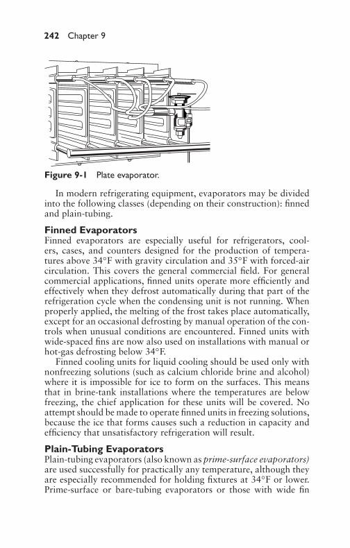
P1: GDZ/FFX P2: GDZ/FFX QC: GDZ/FFX T1: GDZ
GB076-09 GB076-Miller-Sample July 15, 2004 18:30 Char Count= 0
242 Chapter 9
Figure 9-1 Plate evaporator.
In modern refrigerating equipment, evaporators may be dividedinto the following classes (depending on their construction): finnedand plain-tubing.
Finned EvaporatorsFinned evaporators are especially useful for refrigerators, cool-ers, cases, and counters designed for the production of tempera-tures above 34◦F with gravity circulation and 35◦F with forced-aircirculation. This covers the general commercial field. For generalcommercial applications, finned units operate more efficiently andeffectively when they defrost automatically during that part of therefrigeration cycle when the condensing unit is not running. Whenproperly applied, the melting of the frost takes place automatically,except for an occasional defrosting by manual operation of the con-trols when unusual conditions are encountered. Finned units withwide-spaced fins are now also used on installations with manual orhot-gas defrosting below 34◦F.
Finned cooling units for liquid cooling should be used only withnonfreezing solutions (such as calcium chloride brine and alcohol)where it is impossible for ice to form on the surfaces. This meansthat in brine-tank installations where the temperatures are belowfreezing, the chief application for these units will be covered. Noattempt should be made to operate finned units in freezing solutions,because the ice that forms causes such a reduction in capacity andefficiency that unsatisfactory refrigeration will result.
Plain-Tubing EvaporatorsPlain-tubing evaporators (also known as prime-surface evaporators)are used successfully for practically any temperature, although theyare especially recommended for holding fixtures at 34◦F or lower.Prime-surface or bare-tubing evaporators or those with wide fin

P1: GDZ/FFX P2: GDZ/FFX QC: GDZ/FFX T1: GDZ
GB076-09 GB076-Miller-Sample July 15, 2004 18:30 Char Count= 0
Evaporators for Air Conditioners 243
spacing may be operated in a frosted condition for a longer periodwithout materially changing the temperature of the fixture beingcooled. It is necessary, however, to defrost such units at regularintervals to maintain the required temperatures. The coating of frostwill eventually become so thick that the rate of heat transfer will bereduced and often air circulation will be retarded. The defrosting isusually done manually because generally the units are not permittedto enter the ice-melting zone for a sufficient length of time in thenormal refrigeration cycle for automatic defrosting to take place.
Plain-tubing evaporators are recommended for liquid cooling andfor freezing solutions. Ice formation does not affect their capacityand operating efficiency as quickly, and to such an extent, as finnedevaporators.
Evaporator-Coil ConstructionWhen refrigeration evaporators are used for cooling air by forcedconvection, they are usually termed blast coils or unit coolers. Theblast coil is made up of a direct expansion coil mounted in a metalhousing, complete with a fan for forced-air circulation. The coilis normally constructed of copper tubing supported in metal-tubesheets, with aluminum fins on the tubing (as shown in Figure 9-2and Figure 9-3) to increase heat-transfer efficiency.
If the evaporator is quite small, there may be only one continuouscircuit in the coil. However, as the size increases, the increasing pres-sure drop through the longer circuit makes it necessary to divide theevaporator into several individual circuits emptying into a commonheader. The various circuits are usually fed through a distributorthat equalizes the feed in each circuit to maintain high evaporatorefficiency.
The spacing of fins on the refrigerant tubing will vary dependingon the application. Low-temperature coils may have as few as twofins per inch, while air-conditioning coils may have up to 12 ormore per inch. In general, if the evaporator temperature is to bebelow 32◦F so that frost will accumulate, fin spacing of four per inchor less is commonly used, although closer fin spacing is sometimesused if efficient defrost systems are available. In air-conditioningapplications, icing of the coil is seldom a problem, and the limit onfin spacing may be dictated by the coil’s resistance to air flow.
Since the heat-transfer efficiency of the coil increases with anincrease in the mass flow of air passing through it, high velocitiesgreater than 500 to 600 fpm should not be used. Water collectingon the coil from condensation will be blown off into the air streamif these velocities are exceeded.

P1: GDZ/FFX P2: GDZ/FFX QC: GDZ/FFX T1: GDZ
GB076-09 GB076-Miller-Sample July 15, 2004 18:30 Char Count= 0
244 Chapter 9
LIQUID LINE
LIQUID LINE
SUCTIONHEADERS
Figure 9-2 Direct-expansion evaporator showing coil circulation.
Figure 9-3 Evaporator used in air-conditioning systems for the home.The evaporator fits in the forced-air furnace bonnet or plenum. The fanused for heat during the winter is used for circulating air through theevaporator during the summer.

P1: GDZ/FFX P2: GDZ/FFX QC: GDZ/FFX T1: GDZ
GB076-09 GB076-Miller-Sample July 15, 2004 18:30 Char Count= 0
Evaporators for Air Conditioners 245
Refrigerant-Control MethodsTo fully understand the methods of controlling refrigerants in air-conditioning systems, you must first understand superheat, chillingunits, dry-expansion coil arrangements, and capacity requirements.
SuperheatThe superheat at any point in a refrigeration or air-conditioningsystem is found by first measuring the actual refrigerant tempera-ture at that point using an electronic thermometer. Then the boilingpoint temperature of the refrigerant is found by connecting a com-pound pressure gage to the system and reading the boiling temper-ature from the center of the pressure gage. The difference betweenthe actual temperature and the boiling point temperature is super-heat. If the superheat is zero, the refrigerant must be boiling inside,and there is a good chance that some of the refrigerant is still liq-uid. If the superheat is greater than zero (at least 5◦F or better),then the refrigerant is probably past the boiling point and is allvapor.
The method of measuring superheat described here has obviousfaults. If there is no attachment for a pressure gage at the pointin the system where you are measuring superheat, the hypotheticalboiling temperature cannot be found. To determine the superheat atsuch a point, the following method can be used. This method isparticularly useful for measuring the refrigerant superheat in thesuction line.
Instead of using a pressure gage, the boiling point of the refrig-erant in the evaporator can be determined by measuring the tem-perature in the line just after the expansion valve where the boilingis vigorous. This can be done by any electronic thermometer. Asthe refrigerant heats up through the evaporator and the suctionline, the actual temperature of the refrigerant can be measuredat any point along the suction. Comparison of these two tem-peratures gives a superheat measurement sufficient for field ser-vice, unless a distributor-metering device is used, or the evaporatoris very large with a great amount of pressure drop across theevaporator.
It is possible to read superheat directly using a meter made forthe job. This meter works on temperature differential, measuring thetemperature at two points, and then converting this to superheat bysubtracting and presenting the difference.
Figure 9-4 illustrates the way superheat works. The bulb “open-ing” force (F-1) is caused by bulb temperature. This force is balancedagainst the system back pressure (F-2), and the valve spring force
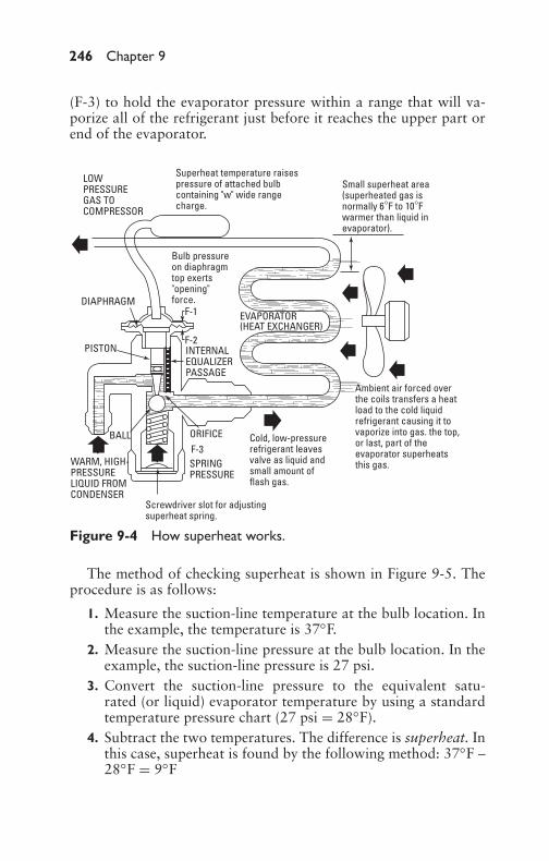
P1: GDZ/FFX P2: GDZ/FFX QC: GDZ/FFX T1: GDZ
GB076-09 GB076-Miller-Sample July 15, 2004 18:30 Char Count= 0
246 Chapter 9
(F-3) to hold the evaporator pressure within a range that will va-porize all of the refrigerant just before it reaches the upper part orend of the evaporator.
LOW PRESSURE GAS TO COMPRESSOR
Superheat temperature raisespressure of attached bulbcontaining "w" wide rangecharge.
Small superheat area(superheated gas isnormally 6°F to 10°Fwarmer than liquid inevaporator).
Bulb pressureon diaphragmtop exerts"opening"force.
EVAPORATOR (HEAT EXCHANGER)
F-1
F-2INTERNALEQUALIZERPASSAGE
DIAPHRAGM
PISTON
BALL
WARM, HIGH-PRESSURELIQUID FROMCONDENSER
Screwdriver slot for adjustingsuperheat spring.
SPRING PRESSURE
ORIFICEF-3
Cold, low-pressurerefrigerant leavesvalve as liquid andsmall amount offlash gas.
Ambient air forced overthe coils transfers a heatload to the cold liquidrefrigerant causing it tovaporize into gas. the top,or last, part of theevaporator superheatsthis gas.
Figure 9-4 How superheat works.
The method of checking superheat is shown in Figure 9-5. Theprocedure is as follows:
1. Measure the suction-line temperature at the bulb location. Inthe example, the temperature is 37◦F.
2. Measure the suction-line pressure at the bulb location. In theexample, the suction-line pressure is 27 psi.
3. Convert the suction-line pressure to the equivalent satu-rated (or liquid) evaporator temperature by using a standardtemperature pressure chart (27 psi = 28◦F).
4. Subtract the two temperatures. The difference is superheat. Inthis case, superheat is found by the following method: 37◦F –28◦F = 9◦F

P1: GDZ/FFX P2: GDZ/FFX QC: GDZ/FFX T1: GDZ
GB076-09 GB076-Miller-Sample July 15, 2004 18:30 Char Count= 0
Evaporators for Air Conditioners 247
37°F(34 PSI)
BULB
27 PSI(28°F)
34 PSI
27 PSI+ 7 PSI34 PSI
BALANCE
SPRING(7 PSI)
(27 PSI)
DIAPHRAGMEVAPORATOR
SUPERHEATSUCTION TEMP. AT BULB.............................. 37°FSATURATED REFRIGERANT TEMP.(EQUIVALENT TO EVAPORATOR OUTLETPRESSURE OF 27 PSI)..................................... 28°F
9°FSUPERHEAT=
Figure 9-5 Where and how to check superheat.
Suction pressure at the bulb may be obtained by either of thefollowing methods:
1. If the valve has an external equalizer line, the gage in this linemay be read directly.
2. If the valve is internally equalized, take a pressure gage readingat the compressor base valve. Add to this the estimated pres-sure drop between the gage and the bulb location. The sumwill approximate the pressure at the bulb.
The system should be operating normally when the superheat isbetween 6◦F and 10◦F.
Chilling UnitsThree types of evaporators or chilling units are in general use:flooded, wet expansion, and dry expansion. The type of evaporator

P1: GDZ/FFX P2: GDZ/FFX QC: GDZ/FFX T1: GDZ
GB076-09 GB076-Miller-Sample July 15, 2004 18:30 Char Count= 0
248 Chapter 9
differs with respect to the volume of liquid refrigerant permitted ineach and with the refrigerant-control methods.
Although the purpose of each of the evaporator types is the same,each varies with respect to its operation. Thus, the flooded type isoperated with approximately 75 percent of its total capacity of liquidrefrigerant. Control of the refrigerant level is generally maintainedby the use of a high- or low-side float control.
A heat exchanger is generally required in flooded evaporator in-stallations to ensure that the suction gas will be superheated. Liquidrefrigerant will enter the suction line from the oil-return line. Theheat exchanger is necessary to vaporize the liquid refrigerant so thatit will not return to the compressor as a slug and make the valvesinoperative. An oil separator is also desirable to ensure minimumoil circulation through the system. Flooded operation of evapora-tors using refrigerants such as Freon-12 and Freon-22 can result inproblems in oil trapping.
The wet-expansion type of evaporator is usually liquid-filled toapproximately 50 percent. In this type, the refrigerant mixture flowsthrough the tubes with a rather slow velocity because of large tubediameters, and the possibility of having entrained liquid in the va-por entering the suction line is not pronounced. This permits moreof the tail end of the evaporator to be used than would be possi-ble if the vapor velocity were higher. At the same time, it ensurespositive oil return due to short vapor paths. The temperature differ-ence between the inlet and outlet or superheat of vapor leaving theevaporator should range between 5◦F and 7◦F, with the latter valueon low average-refrigerant-temperature application. The efficiencyof an evaporator will be affected 10 to 20 percent by increasing thesuperheat a few degrees above design conditions, which is attempt-ing, in effect, to refrigerate with vapor.
The dry-expansion type of evaporator is of the continuous tubeconstruction. The percentage of evaporator volume filled with liquidis approximately 25 percent. In this type of evaporator, the velocityof the refrigerant mixture is high, causing a turbulent or swirlingcondition, which throws the liquid refrigerant against the sides ofthe tube. Therefore, it is necessary to operate with a higher super-heat to prevent carrying entrained liquid refrigerant into the suc-tion line. This type of evaporator is usually operated with from 9◦Fto 12◦F superheat. The velocity of the vapor in the evaporator in-creases with the length. In general, the pressure drop through anevaporator is half what it would be if the same amount of pipe ortubing were used as a suction line carrying the same quantity ofvapor.

P1: GDZ/FFX P2: GDZ/FFX QC: GDZ/FFX T1: GDZ
GB076-09 GB076-Miller-Sample July 15, 2004 18:30 Char Count= 0
Evaporators for Air Conditioners 249
A pipe-coil installation is normally operated at approximately10◦F superheat, depending on the refrigerant temperature, andusually requires a heat exchanger or drier oil due to the lowtemperature. This type of evaporator is used all the way fromultra low-temperature refrigeration applications up to comfortair-conditioning levels. Evaporators of the foregoing types employan automatic or thermostatic expansion valve to control the liquidrefrigerant. It should be noted, however, that different settings ofthe expansion valves are required for each type of evaporator.
Dry-Expansion Coil ArrangementsAlthough there are many ways of arranging dry-expansion coils, thefollowing are the most common:
1. By top feed, free-draining piping at a vertical up-flow coil, asshown in Figure 9-6.
2. By a horizontal airflow coil (see Figure 9-7) in which the suc-tion is taken off the bottom header connection, thus providingfree oil draining.
3. By a refrigerant bottom-feed coil with a vertical down-flow airarrangement, as shown in Figure 9-8.
Air flowif compressor is below
loop suction to top of coil.LIQUID LINE
EQUALIZERLINE
EXPANSIONVALVE
SUCTIONHEADER
Figure 9-6 Coils in a top-feed, direct-expansion evaporator.
Many coils are supplied with connections at each end of thesuction header so that the free-draining connection can be usedregardless of which side of the coil is up; the other end is then capped.The preceding arrangements have no oil-trapping problems. Witha bottom-feed coil evaporator, such as shown in Figure 9-8, it is
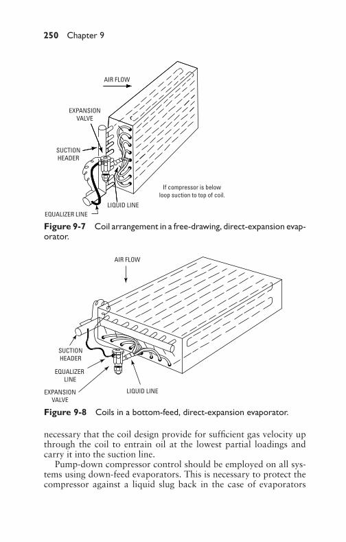
P1: GDZ/FFX P2: GDZ/FFX QC: GDZ/FFX T1: GDZ
GB076-09 GB076-Miller-Sample July 15, 2004 18:30 Char Count= 0
250 Chapter 9
LIQUID LINEEQUALIZER LINE
AIR FLOW
EXPANSIONVALVE
SUCTIONHEADER
If compressor is belowloop suction to top of coil.
Figure 9-7 Coil arrangement in a free-drawing, direct-expansion evap-orator.
LIQUID LINE
EQUALIZER LINE
AIR FLOW
EXPANSIONVALVE
SUCTIONHEADER
Figure 9-8 Coils in a bottom-feed, direct-expansion evaporator.
necessary that the coil design provide for sufficient gas velocity upthrough the coil to entrain oil at the lowest partial loadings andcarry it into the suction line.
Pump-down compressor control should be employed on all sys-tems using down-feed evaporators. This is necessary to protect thecompressor against a liquid slug back in the case of evaporators
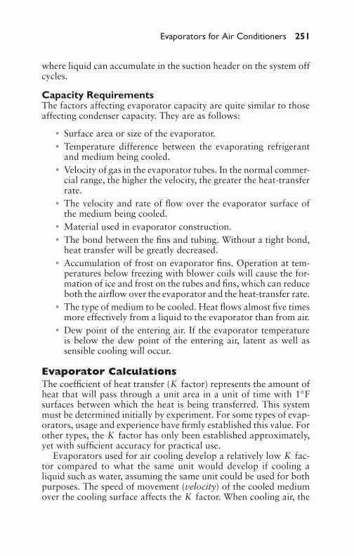
P1: GDZ/FFX P2: GDZ/FFX QC: GDZ/FFX T1: GDZ
GB076-09 GB076-Miller-Sample July 15, 2004 18:30 Char Count= 0
Evaporators for Air Conditioners 251
where liquid can accumulate in the suction header on the system offcycles.
Capacity RequirementsThe factors affecting evaporator capacity are quite similar to thoseaffecting condenser capacity. They are as follows:
� Surface area or size of the evaporator.� Temperature difference between the evaporating refrigerant
and medium being cooled.� Velocity of gas in the evaporator tubes. In the normal commer-
cial range, the higher the velocity, the greater the heat-transferrate.� The velocity and rate of flow over the evaporator surface of
the medium being cooled.� Material used in evaporator construction.� The bond between the fins and tubing. Without a tight bond,
heat transfer will be greatly decreased.� Accumulation of frost on evaporator fins. Operation at tem-
peratures below freezing with blower coils will cause the for-mation of ice and frost on the tubes and fins, which can reduceboth the airflow over the evaporator and the heat-transfer rate.� The type of medium to be cooled. Heat flows almost five times
more effectively from a liquid to the evaporator than from air.� Dew point of the entering air. If the evaporator temperature
is below the dew point of the entering air, latent as well assensible cooling will occur.
Evaporator CalculationsThe coefficient of heat transfer (K factor) represents the amount ofheat that will pass through a unit area in a unit of time with 1◦Fsurfaces between which the heat is being transferred. This systemmust be determined initially by experiment. For some types of evap-orators, usage and experience have firmly established this value. Forother types, the K factor has only been established approximately,yet with sufficient accuracy for practical use.
Evaporators used for air cooling develop a relatively low K fac-tor compared to what the same unit would develop if cooling aliquid such as water, assuming the same unit could be used for bothpurposes. The speed of movement (velocity) of the cooled mediumover the cooling surface affects the K factor. When cooling air, the

P1: GDZ/FFX P2: GDZ/FFX QC: GDZ/FFX T1: GDZ
GB076-09 GB076-Miller-Sample July 15, 2004 18:30 Char Count= 0
252 Chapter 9
K factor will vary somewhat with the conditions of the coolingsurface.
The amount of heat that can be absorbed by an evaporator (thatis, its capacity) follows the fundamental heat-transfer equation:
H = KATd
where the following is true:
K = coefficient of heat transferA = total evaporator area (square feet)
Td = temperature differences between refrigerant and mediumbeing cooled
Therefore, if it is desired to handle a given quantity of heat in astated period of time, simple mathematics show that a compensatingvariation must be made in one or both of the remaining factors tohold the capacity H constant.
The following general conditions affect the K factor of any evap-orator:� Physical construction� Conditions on the exterior of the evaporator� Conditions on the interior of the evaporator� Relation of refrigerant flow to medium being cooled
Some of these factors are difficult to segregate clearly becausethey interlock with each other. The K factor of finned tubing andsurfaces varies greatly and must be determined by tests for eachtype of construction. With a finned evaporator, the relation of thetotal surface area to surface area of tubing containing the liquidrefrigerant is important. This is sometimes called the R factor andmay be written as follows:
R = tube areatotal area
The greater the area of fins in proportion to the tubing area, thelower the overall K factor of the evaporator. The physical construc-tion of fins has an effect on the K factor. Finned area extendedtoo far from the tubing becomes ineffective and may be just wastedmetal. Spacing of fins is important because it affects the K factor andbecause of its relation to frost formation on cooling units. Closelyspaced fins may easily accumulate sufficient frost between them tocompletely stop air circulation through the unit and are then difficultto defrost. As a rule, the area of an evaporator is the total surface

P1: GDZ/FFX P2: GDZ/FFX QC: GDZ/FFX T1: GDZ
GB076-09 GB076-Miller-Sample July 15, 2004 18:30 Char Count= 0
Evaporators for Air Conditioners 253
exposed to the medium being cooled. Area is only one of three fac-tors determining the heat-handling capacity of an evaporator. Itsimportance is often overemphasized.
Exterior ConditionsConditions on the exterior of the evaporator that affect the coeffi-cient of heat transfer are:
� Medium being cooled� Velocity of cooled medium over cooling unit surface� Condition of exterior surface� Temperature of medium being cooled
Surface-Area DeterminationIn determining surfaces, it should be noted that the plain-tubingtype will have a higher K than the finned construction. The finned-surface evaporator, however, will often permit the use of more heat-absorbing surface in the space allowed for the cooling unit, and hasbeen used more in recent years than the plain-tubing evaporator. Theevaporator surface-area determination is illustrated in the followingexample.
ExampleIf it is assumed that a tube evaporator has a K of 2 and a finned-tubeevaporator has a K value of 0.5, calculate the required tube surfaceof each when it takes a Td of 20◦F to produce 10,000 Btu/hr.
SolutionSubstitution of values in the heat-transfer formula for the plain-surface evaporator gives:
A = HK × Td
= 10,0002 × 20
= 250 ft2 of tube surface
Similarly, for the finned-surface evaporator:
A = 10,0000.5 × 20
= 1000 ft2 of tube surface
P1: GDZ/FFX P2: GDZ/FFX QC: GDZ/FFX T1: GDZ
GB076-09 GB076-Miller-Sample July 15, 2004 18:30 Char Count= 0
254 Chapter 9
ExampleIf 10,000 Btu/hr are to be absorbed in an evaporator having aK factor of 10 and an A of 100, what is the temperature differ-ence between the refrigerant and the medium being cooled?
SolutionWith reference to the heat-transfer formula, use the following for-mula:
H = KATd
or
10,000 = 10 × 100 × Td
Td = 10,00010 × 100
= 10◦
If the K factor has been reduced for some reason to 2, the productof A and Td would have to be raised to 5000 if H is to remain at10,000:
H = KATd
or
10,000 = 2 × 100 × Td
A × Td = 10,0002
= 5000
So, if A remains at 100, Td would have to be 50:
H = KATd
or
10,000 = 2 × A × Td
Td = 10,0002 × 100
= 50◦
If K and A are fixed quantities (for example, K = 2 andA = 200), and Td is varied, H will be found to vary directly asTd varies. For example, if Td = 20, H = 8000; if Td = 10, H =4000.
P1: GDZ/FFX P2: GDZ/FFX QC: GDZ/FFX T1: GDZ
GB076-09 GB076-Miller-Sample July 15, 2004 18:30 Char Count= 0
Evaporators for Air Conditioners 255
The preceding example illustrates the change necessary in Tdshould some of the factors affecting K be violated.
Evaporator MaintenanceFor low-temperature applications with dry-coil–type units, defrost-ing can be obtained by providing arrangements for the intake ofoutside air and the exhaust of this air to the outside during the de-frosting period. It should be noted, however, that the outside tem-perature must be above 35◦F when using this defrosting method.At very low temperatures, hot-gas defrosting may be employed onlywhen there is more than one evaporator connected to a condensingunit, so that the other unit can continue to provide refrigeration tothe fixture.
Where operating conditions (design-fixture temperature, operat-ing refrigerant temperature, and condensing-unit running time) willpermit, the removal of frost may be accomplished automatically byuse of controls normally supplied with condensing units by mostmanufactures. By proper adjustment of these controls, the condens-ing unit is cycled to suit the job at hand.
Another variety of automatic defrosting can be obtained on someinstallations by the use of a time clock that will shut the systemdown at suitable and convenient intervals and return it to normaloperation thereafter. This system is usable only as a general rulewhen fixture temperatures of around 32◦F or higher are employedor when the fixture can be quickly warmed up to approximately35◦F in a reasonable period.
Cycling the Condensing UnitThe first method described (cycling the condensing unit) is decidedlypreferable when it can be used. It does not require the purchase andinstallation of special equipment and permits the use of controlsnormally furnished with a condensing unit by most manufacturers.
In certain types of refrigeration requiring frosted evaporators,it is impossible to defrost automatically by normal cycling of thecondensing unit. Therefore, it is necessary to defrost by mechanicalmethods or by shutting down the system. The mechanical methodrequires the use of picks and scrapers to remove the ice and frostaccumulated. This calls for the use of steel-pipe or plate-type coolingunits, which are sturdy enough to withstand the action of thesedefrosting instruments. Finned or copper tubing evaporators shouldnot be specified where mechanical defrosting is used because theywould be damaged (and possibly made inoperative) by the use ofpicks and scrapers.
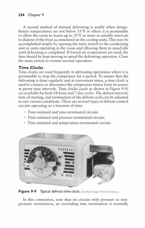
P1: GDZ/FFX P2: GDZ/FFX QC: GDZ/FFX T1: GDZ
GB076-09 GB076-Miller-Sample July 15, 2004 18:30 Char Count= 0
256 Chapter 9
A second method of manual defrosting is usable when design-fixture temperatures are not below 35◦F or where it is permissibleto allow the room to warm up to 35◦F or more at suitable intervalsto dispose of the frost accumulated on the cooling units. This may beaccomplished simply by opening the main switch to the condensingunit or units operating in the room and allowing them to stand idleuntil defrosting is completed. If forced-air evaporators are used, thefans should be kept moving to speed the defrosting operation. Closethe main switch to resume normal operation.
Time ClocksTime clocks are used frequently in defrosting operations where it ispermissible to stop the compressor for a period. To ensure that thedefrosting is done regularly and at convenient times, a time clock isused to connect or disconnect the compressor motor from its sourceat preset time intervals. Time clocks (such as shown in Figure 9-9)are available for both 24-hour and 7-day cycles. The defrost interval,time of starting, and termination of the defrost cycle can be adjustedto suit various conditions. There are several types of defrost-controlcircuits operating as a function of time:� Time-initiated and time-terminated circuits� Time-initiated and pressure-terminated circuits� Time-initiated and temperature-terminated circuits
Figure 9-9 Typical defrost time clock. (Courtesy Paragon Electric Company.)
In this connection, note that on circuits with pressure or tem-perature termination, an overriding time termination is normally
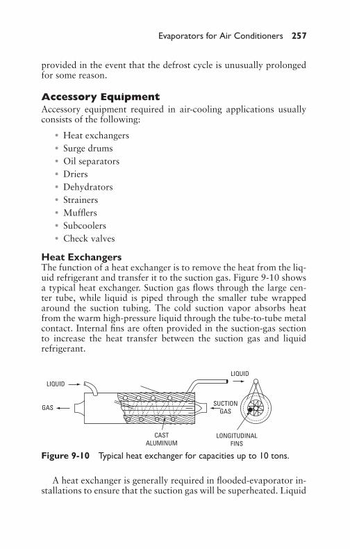
P1: GDZ/FFX P2: GDZ/FFX QC: GDZ/FFX T1: GDZ
GB076-09 GB076-Miller-Sample July 15, 2004 18:30 Char Count= 0
Evaporators for Air Conditioners 257
provided in the event that the defrost cycle is unusually prolongedfor some reason.
Accessory EquipmentAccessory equipment required in air-cooling applications usuallyconsists of the following:� Heat exchangers� Surge drums� Oil separators� Driers� Dehydrators� Strainers� Mufflers� Subcoolers� Check valves
Heat ExchangersThe function of a heat exchanger is to remove the heat from the liq-uid refrigerant and transfer it to the suction gas. Figure 9-10 showsa typical heat exchanger. Suction gas flows through the large cen-ter tube, while liquid is piped through the smaller tube wrappedaround the suction tubing. The cold suction vapor absorbs heatfrom the warm high-pressure liquid through the tube-to-tube metalcontact. Internal fins are often provided in the suction-gas sectionto increase the heat transfer between the suction gas and liquidrefrigerant.
LONGITUDINALFINS
LIQUID
SUCTIONGAS
LIQUID
GAS
CASTALUMINUM
Figure 9-10 Typical heat exchanger for capacities up to 10 tons.
A heat exchanger is generally required in flooded-evaporator in-stallations to ensure that the suction gas will be superheated. Liquid
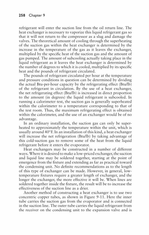
P1: GDZ/FFX P2: GDZ/FFX QC: GDZ/FFX T1: GDZ
GB076-09 GB076-Miller-Sample July 15, 2004 18:30 Char Count= 0
258 Chapter 9
refrigerant will enter the suction line from the oil return line. Theheat exchanger is necessary to vaporize this liquid refrigerant gas sothat it will not return to the compressor as a slug and damage thevalves. The theoretical amount of cooling through the superheatingof the suction gas within the heat exchanger is determined by theincrease in the temperature of the gas as it leaves the exchanger,multiplied by the specific heat of the suction gas and the amount ofgas pumped. The amount of subcooling actually taking place in theliquid refrigerant as it leaves the heat exchanger is determined bythe number of degrees to which it is cooled, multiplied by its specificheat and the pounds of refrigerant circulated.
The pounds of refrigerant circulated per hour at the temperatureand pressure conditions in question can be determined by dividingthe actual Btu-per-hour capacity by the refrigerating effect (Btu/lb)of the refrigerant in circulation. By the use of a heat exchanger,the net refrigerating effect (Btu/lb) is increased in direct proportionto the amount (in degrees) the liquid refrigerant is subcooled. Inrunning a calorimeter test, the suction gas is generally superheatedwithin the calorimeter to a temperature corresponding to that ofthe test room. Thus, the maximum refrigerating effect is obtainedwithin the calorimeter, and the use of an exchanger would be of noadvantage.
In an ordinary installation, the suction gas can only be super-heated to approximately the temperature within the unit, which isusually around 40◦F. In an installation of this kind, a heat exchangerwill increase the net refrigeration (Btu/lb) by taking advantage ofthis cold-suction gas to remove some of the heat from the liquidrefrigerant before it enters the evaporator.
Heat exchangers may be constructed in a number of differentways. Where it is desired to make a low-priced exchanger, the suctionand liquid line may be soldered together, starting at the point ofemergence from the fixture and extending as far as practical towardthe condensing unit. No definite recommendations as to the lengthof this type of exchanger can be made. However, in general, low-temperature fixtures require a greater length of exchanger, and thelonger the exchanger, the more effective it will be. When lines aresoldered together inside the fixture, the result will be to increase theeffectiveness of the suction line as a drier.
Another method of constructing a heat exchanger is to use twoconcentric copper tubes, as shown in Figure 9-11. Here the innertube carries the suction gas from the evaporator and is connectedin the suction line. The outer tube carries the liquid refrigerant fromthe receiver on the condensing unit to the expansion valve and is

P1: GDZ/FFX P2: GDZ/FFX QC: GDZ/FFX T1: GDZ
GB076-09 GB076-Miller-Sample July 15, 2004 18:30 Char Count= 0
Evaporators for Air Conditioners 259
connected to the liquid line. The suction gas travels counter flow tothe liquid refrigerant. Before the exchanger is assembled, the innersurface of both tubes and the outside of the suction-line tube shouldbe cleaned to make sure no dirt or moisture is on the surface, sincethese surfaces are exposed to the refrigerant.
WATER LINE INTOSUB COOLER
SOLDER THRUFEED HOLES ONLY
LIQUID LINE FROMCONDENSING UNIT
LIQUID LINE TOEVAPORATOR
WATER LINE FROMSUB COOLER
Figure 9-11 Sectional view of typical two-pipe heat exchangers.
As the liquid section of the exchanger must be full to be mosteffective, it will be necessary to add refrigerant to the system toensure this condition. When installing the exchanger, it should bemounted as near to the fixture as possible. It should be located onthe outside of the fixture when space is available. If mounted insidethe fixture, it should be insulated. The pressure drop through theexchanger should be added to the pressure drop through the rest ofthe suction line to determine the entire line drop.
Certain types of installations spill large quantities of liquid refrig-erant when starting, or may be subject to temporary surges. Low-temperature and pipe-coil applications are most prominent in thisregard. Such liquid surges may pass through an otherwise satis-factory exchanger. To prevent this, an accumulator effect may beprovided in the exchanger. Excess liquid will be collected in the

P1: GDZ/FFX P2: GDZ/FFX QC: GDZ/FFX T1: GDZ
GB076-09 GB076-Miller-Sample July 15, 2004 18:30 Char Count= 0
260 Chapter 9
accumulator exchanger until its refrigerating effect has been ab-sorbed by the warm liquid. Such an operation will prevent the lossof refrigerating effect of “spillover” liquid, as well as any possibledamage to the compressor from this condition.
Surge DrumsSurge drums, also termed suction accumulators (see Figure 9-12), arerequired on the suction side of almost all flooded-type evaporatorsto prevent liquid slop over to the compressor. The exceptions areshell-and-tube coolers and similar shell-type evaporators, which aredesigned to provide ample surge space above the liquid level, orwhich contain eliminators for the separation of gas and liquid.
FROM COILCOMPRESSOR
METERINGORIFICE
Figure 9-12 Typicalsuction accumulator.(Courtesy Refrigeration Research, Inc.)
A horizontal surge drum is sometimes used where headroom islimited. The drum may be designed with baffles or eliminators toseparate the liquid from the suction gas returning from the top ofthe shell to the compressor. More often, there is space allowed forsufficient separation above the liquid level. Such a design is usuallyof the vertical type with a separation height above the liquid level.The level is from 24 to 30 inches and with the shell diameter sizedto keep the suction-gas velocity at a low enough value to allow theliquid droplets to separate and not be entrained with the returningsuction gas from the top of the shell.
Oil SeparatorsWhen used, oil separators are installed in the discharge line betweenthe compressor and receiver. As shown in Figure 9-13, oil separatorsare used because refrigerants and oil are mixed in a refrigerant sys-tem. Unless some device is used to prevent it, oil will be carried
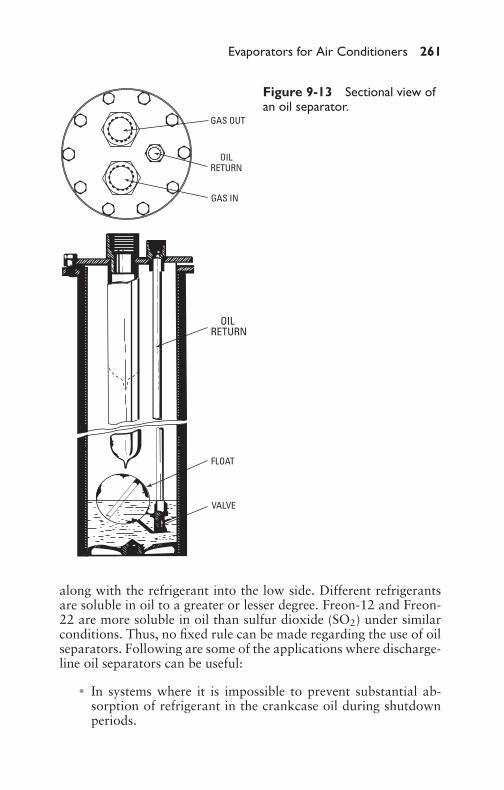
P1: GDZ/FFX P2: GDZ/FFX QC: GDZ/FFX T1: GDZ
GB076-09 GB076-Miller-Sample July 15, 2004 18:30 Char Count= 0
Evaporators for Air Conditioners 261
GAS OUT
OILRETURN
GAS IN
OIL RETURN
FLOAT
VALVE
Figure 9-13 Sectional view ofan oil separator.
along with the refrigerant into the low side. Different refrigerantsare soluble in oil to a greater or lesser degree. Freon-12 and Freon-22 are more soluble in oil than sulfur dioxide (SO2) under similarconditions. Thus, no fixed rule can be made regarding the use of oilseparators. Following are some of the applications where discharge-line oil separators can be useful:
� In systems where it is impossible to prevent substantial ab-sorption of refrigerant in the crankcase oil during shutdownperiods.

P1: GDZ/FFX P2: GDZ/FFX QC: GDZ/FFX T1: GDZ
GB076-09 GB076-Miller-Sample July 15, 2004 18:30 Char Count= 0
262 Chapter 9
� In systems using flooded evaporators where refrigerant bleedoff is necessary for oil removal from the evaporator.� In direct-expansion systems using coils or tube bundles that
require bottom feed for good liquid distribution, and whererefrigerant slop-over is essential from the top of the evaporatorfor proper oil removal.� In low-temperature systems where it is advantageous to have
as little oil as possible going through the low side (especiallyFreon-13 systems, where the oil is not miscible with the refrig-erant).
In applying oil separators in refrigeration systems, certain poten-tial hazards must be fully recognized and properly dealt with:� The main hazard to guard against in the use of oil separators is
their tendency to condense-out liquid refrigerant during com-pressor off cycles and compressor startup. This is true if thecondenser is in a warm location (such as an evaporative con-denser and receiver on a roof). During the off cycle, the oilseparator cools down and acts as a condenser for liquid refrig-erant that evaporates in warmer parts of the system. Thus, acool oil separator will act as a liquid condenser during off cy-cles and on compressor startup until the separator has warmedup. It will automatically drain this condensed liquid into thecompressed crankcase. On startup, there is excessive boilingin the crankcase because of the presence of a large amount ofliquid refrigerant. This will result in poor lubrication and wearon the compressor, and may even end up completely drainingthe oil out of the crankcase as a result of this violent boilingaction. If not protected by an oil-safety switch, compressorfailure may result.� Oil separators are not 100 percent efficient, and, therefore, it
is still necessary to design the complete system for oil returnto the compressor.� The float valve is a mechanical device that may stick open or
closed. If it sticks open, hot gas will be continuously bypassedto the compressor crankcase, which will cause the compressorto operate at an elevated temperature and, of course, reducecapacity. If the valve sticks closed, then no oil is returned tothe compressor.
Where oil separators are used, it is recommended that precau-tions be taken to prevent draining condensed refrigerant into the

P1: GDZ/FFX P2: GDZ/FFX QC: GDZ/FFX T1: GDZ
GB076-09 GB076-Miller-Sample July 15, 2004 18:30 Char Count= 0
Evaporators for Air Conditioners 263
crankcase. To minimize this possibility, the drain connection fromthe oil separator can be connected into the suction line entering thecompressor. In this way, any liquid refrigerant returning from theseparator will go into the suction manifold rather than directly intothe crankcase. This drain line should be equipped with a shutoffvalve, hand-throttling valve, solenoid valve, and sight glass. Thethrottling valve should be adjusted so that the flow through this lineis very small, in fact, only a little greater than would be normallyexpected for the return of oil through the suction line. The use ofthe sight glass will help in adjusting this flow. The solenoid valveshould be wired so that it is open when the compressor is running,and is closed when the compressor is off.
The preceding arrangement will prevent liquid from drainingdown into the compressor during an off cycle. When the compres-sor starts up with liquid refrigerant in the oil separator, it will alsoprevent this liquid from dumping directly into the crankcase. It willallow it to be bled slowly into the suction line, where it can betaken care of in the normal manner, similar to oil returning fromthe system.
The hazard of draining condensed refrigerant into the crankcasecan also be minimized by insulating the oil separator and installingit ahead of a hot-gas loop to the floor so that there will be a trap be-tween it and any evaporative condenser installed above. Insulatingthe oil separator keeps it warm for a longer period after shutdownof the compressor and cuts down on the amount of condensationin the shell during shutdown, unless it is for a prolongedperiod.
A manufacturer of some units returns oil from an oil separatorthrough an oil reservoir. This oil is heated, boiling off the refriger-ant into the suction line. Return of liquid refrigerant from an oilseparator to the compressor crankcase is a serious hazard.
DriersThe function of a drier in a refrigeration system is to remove mois-ture. The use of a permanent refrigerant drier was recommendedon older systems using Freon-12 and Freon-22. It is necessary onall low-temperature systems, including those using Freon-13. Thedecision of whether or not to use a permanent drier on higher-temperature systems is one of judgment. In the case of package-typeair conditioners and water chillers, it may not be necessary if properdehydration techniques have been followed at the factory, no refrig-erant connections are broken in the field, and any refrigerant addedis of a sufficiently low moisture content. If there is any doubt that
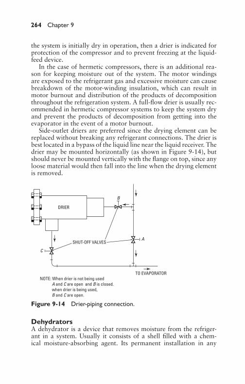
P1: GDZ/FFX P2: GDZ/FFX QC: GDZ/FFX T1: GDZ
GB076-09 GB076-Miller-Sample July 15, 2004 18:30 Char Count= 0
264 Chapter 9
the system is initially dry in operation, then a drier is indicated forprotection of the compressor and to prevent freezing at the liquid-feed device.
In the case of hermetic compressors, there is an additional rea-son for keeping moisture out of the system. The motor windingsare exposed to the refrigerant gas and excessive moisture can causebreakdown of the motor-winding insulation, which can result inmotor burnout and distribution of the products of decompositionthroughout the refrigeration system. A full-flow drier is usually rec-ommended in hermetic compressor systems to keep the system dryand prevent the products of decomposition from getting into theevaporator in the event of a motor burnout.
Side-outlet driers are preferred since the drying element can bereplaced without breaking any refrigerant connections. The drier isbest located in a bypass of the liquid line near the liquid receiver. Thedrier may be mounted horizontally (as shown in Figure 9-14), butshould never be mounted vertically with the flange on top, since anyloose material would then fall into the line when the drying elementis removed.
B
A
DRIER
C
SHUT-OFF VALVES
NOTE: When drier is not being used A and C are open and B is closed. when drier is being used, B and C are open.
TO EVAPORATOR
Figure 9-14 Drier-piping connection.
DehydratorsA dehydrator is a device that removes moisture from the refriger-ant in a system. Usually it consists of a shell filled with a chem-ical moisture-absorbing agent. Its permanent installation in any

P1: GDZ/FFX P2: GDZ/FFX QC: GDZ/FFX T1: GDZ
GB076-09 GB076-Miller-Sample July 15, 2004 18:30 Char Count= 0
Evaporators for Air Conditioners 265
field-connected installation is extremely desirable for both economyand operation. Its first cost is negligible compared to the serviceparts and labor it will save and the improvement in expansion-valveoperation by the elimination of moisture.
In systems that are field-connected, there is always a possibilityof taking in moisture. This is especially true where connections aremade hastily or carelessly. Even carefully made connections maybe loosened by continued vibration or possible abuse after installa-tion. Obviously, these leaks should be repaired as soon as they aredetected. Before detection, however, considerable moisture may beabsorbed by the system, especially on low-temperature installations.Damage from such sources may be avoided if a dehydrator has beeninstalled as a permanent fixture.
Temporary dehydrator installation as a service procedure to over-come moisture is necessary, but two things must be kept in mind.First, the condition probably would not have developed had a per-manent dehydrator been installed. Second, when the temporarydehydrator is removed, the system is necessarily opened up andmoisture is given a chance to re-enter, nullifying all the good thathad been accomplished. These points further emphasize the advis-ability of installing permanent dehydrators at the time of originalinstallation.
The dehydrating agent used is capable of absorbing only a certainamount of moisture. Should a greater quantity of moisture get intothe system, the dehydrator will become saturated and inactive, andthen must be replaced or refilled. Should dehydrators be openedor not tightly sealed in the stockroom, they will absorb moisturefrom the air, becoming saturated and inactive if put on an installa-tion. Therefore, be sure the dehydrating agent is still active in anydehydrator that is to be installed.
StrainersStrainers (or filters, as they are sometimes called) are used to filteror strain out undesirable material (Figure 9-15). Their function isto protect all automatic valves and the compressor from foreignmaterial (such as pipe scale, rust, and metal chips) in the system.
Refrigeration systems usually have strainers at several points, forexample:� At the liquid-line outlet for the receiver� At the expansion-valve inlet� Ahead of the solenoid valves� At the inlet side of the water valve

P1: GDZ/FFX P2: GDZ/FFX QC: GDZ/FFX T1: GDZ
GB076-09 GB076-Miller-Sample July 15, 2004 18:30 Char Count= 0
266 Chapter 9
TUBING STOP
VALVECONNECTION
STRAINER
TUBING
Figure 9-15 Strainer inserted in a refrigeration system’s tubing. Notedirection of flow. (Courtesy Sporlan Valve.)
Installation of a liquid-line strainer in front of each automaticvalve is recommended to prevent particles from lodging on the valveseats. Where multiple expansion valves with internal strainers areused at one location, a single, main liquid-line strainer will be suffi-cient to protect the system. Care should be taken to pipe the suctionline at the compressor so that the built-in strainer is accessible forservicing.
Both the liquid and suction-line strainers should be properly sizedto ensure adequate foreign-material storage capacity without exces-sive pressure drop. In steel-piping systems, it is recommended that anexternal suction-line strainer be used in addition to the compressorstrainer.
MufflersNoise in hot-gas lines between interconnected compressors andevaporative condensers may be eliminated by the installation of muf-flers. This noise may be particularly noticeable in large installationsand is usually caused by the pulsations in gas flow caused by thereciprocating action of the compressors and velocity of gas throughthe hot-gas line from the compressor. The proper location of a muf-fler is in a horizontal or down portion of the hot-gas line, immedi-ately after leaving the compressor. It should never be installed in ariser.
SubcoolersThe problem of decreased system capacity caused by excessivevertical lifts in the liquid line is usually solved by installation of

P1: GDZ/FFX P2: GDZ/FFX QC: GDZ/FFX T1: GDZ
GB076-09 GB076-Miller-Sample July 15, 2004 18:30 Char Count= 0
Evaporators for Air Conditioners 267
subcoolers. The decrease in system capacity is attributable to twofactors:� Operating head pressures must be increased to offset the static
pressure exerted by the long vertical column of liquid refriger-ant. Thus, condensing-unit capacity is decreased.� Since liquid refrigerant follows definite pressure-temperature
relations, the large fall in pressure caused by long vertical liftsshould be accompanied by a decrease in temperature if a solidcolumn of liquid is to be maintained up to the expansion valve.Pressure and temperature drop will be accompanied by theevaporation of liquid refrigerant. This forms gas in the liquidline, and since gas has a larger volume per pound than liquidrefrigerant, an expansion valve will handle a smaller numberof pounds of liquid and gas than it will liquid in a unit of time.Thus, expansion-valve capacity is decreased.
A subcooler installed in the liquid line (as shown in Fig-ure 9-16) will eliminate this decrease in capacity by supplying anexternal cooling source to reduce the temperature of the liquid re-frigerant. Thus, a solid column of liquid is maintained at the valve.The valve capacity, therefore, is unaffected. The subcooling of theliquid also improves the quality of the refrigerant enough so that,even though condensing-unit head pressures are increased, the evap-orator performance is not decreased.
Check ValvesCheck valves are used in the suction line of low-temperature fixtureswhen they are multiplied with high-temperature fixtures. Their useis most important when the condensing unit is controlled by low-pressure control. Figure 9-17 illustrates their application.
During idle periods of the condensing unit, if there is no checkvalve in the suction line from the evaporator C, some of the refrig-erant vapors from evaporator A will back up into evaporator C.The refrigerant from evaporator A will be condensed in evapora-tor C, causing at least two difficulties. First, heat is added into thecold evaporator C from the condensing process. This causes a de-crease in the refrigerating effect. Second, the pressure that shouldhave started the condensing unit to supply refrigeration to evap-orator A has been reduced and the condensing unit will remainidle.
The foregoing outlined performance will give erratic temperaturecontrol. A check valve is important for accurate temperature control

P1: GDZ/FFX P2: GDZ/FFX QC: GDZ/FFX T1: GDZ
GB076-09 GB076-Miller-Sample July 15, 2004 18:30 Char Count= 0
268 Chapter 9
FROM WATER TOWER
TO WATER TOWER
HANDBY-PASS
VALVEFILTER
REFRIGERANTSUB-COOLER
FROM REFRIGERATORWALL TO SUB-COOLER
REFRIGERATORWALL
EVAPORATOR
CIRCULATINGPUMP
RECEIVER
INSULATED LIQUID LINE
Figure 9-16 Installation of subcooler on city water pressure.
with low-pressure switches on installations involving two or morefixtures where there is a wide variation in temperature. This is par-ticularly true if the low-temperature fixture has a large evaporatorin proportion to the warm evaporator and if it has long holdoverperiods.

P1: GDZ/FFX P2: GDZ/FFX QC: GDZ/FFX T1: GDZ
GB076-09 GB076-Miller-Sample July 15, 2004 18:30 Char Count= 0
Evaporators for Air Conditioners 269
24°F 3°F –10°F
TEMP.EXPANSION
VALVE
AUTOEXPANSION
VALVE
EVAPORATORS
SOLENOID VALVES
CHECK VALVE
A B C
E
S S
Figure 9-17 Installation of suction-line check valve.
SummaryThe principle that heat always flows from a warmer to a colder sur-face makes the evaporators operate. In modern refrigerating equip-ment, evaporators may be divided into the following classes (de-pending on their construction): finned or plain-tubing.
The finned class of evaporator is ordinarily useful for refrigera-tors, coolers, cases, and counters designed for the production oftemperatures above 34◦F with gravity circulation and 35◦F withforced-air circulation.
Plain-tubing evaporators are also known as prime-surface evap-orators. They are used successfully for practically any temperature,although they are especially recommended for holding fixtures 34◦For lower.
Three types of evaporators or chilling units are in general use:flooded, wet-expansion, and dry-expansion. The type of evaporatordiffers with respect to the volume of liquid refrigerant permittedin each and with the refrigerant-control methods. Factors affectingevaporator capacity are quite similar to those affecting condensercapacity.

P1: GDZ/FFX P2: GDZ/FFX QC: GDZ/FFX T1: GDZ
GB076-09 GB076-Miller-Sample July 15, 2004 18:30 Char Count= 0
270 Chapter 9
The amount of heat that can be absorbed by an evapora-tor (that is, its capacity) follows the fundamental heat-transferequation:
H = KATd
where, K is the coefficient of heat transfer, A is the total evaporatorarea in square feet, and Td is the temperature differences betweenthe refrigerant and the medium being cooled.
Time clocks are used frequently in defrosting systems where it ispermissible to stop the compressor for a period. There are severaltypes of defrost-control circuits operating as a function of time:time-initiated and time-terminated; time-initiated and pressure-terminated; and time-initiated and temperature-terminated.
The function of a heat exchanger is to remove the heat from theliquid refrigerant and transfer it to the suction gas. A heat exchangeris generally required in flooded-evaporator installations to ensurethat the suction gas will be superheated.
Surge drums are required on the suction side of almost all flooded-type evaporators to prevent liquid slop-over onto the compressor.
When used, oil separators are installed in the discharge line be-tween the compressor and receiver. They are used because refriger-ants and oil are mixed in a refrigerant system. Unless some device isused to prevent it, oil will be carried along with the refrigerant intothe low side. Where oil separators are used, it is recommended thatprecautions be taken to prevent draining condensed refrigerant intothe crankcase.
Refrigerant driers in a refrigeration system are used to removemoisture. They are necessary on almost all low-temperature systems.
A dehydrator is a device that removes moisture from the refrig-erant in a system. It usually consists of a shell filled with a chemicalmoisture-absorbing agent. In systems that are field-connected, thereis always a possibility of taking in moisture.
Strainers are sometimes called filters because they filter, or strainout, undesirable material. Their function is to protect all automaticvalves and the compressor from foreign material in the system. Suchforeign material may be rust, scale, metal chips, or any numberof other things that can get into a system during installation andmanufacture.
Noise in hot-gas lines between interconnected compressors andevaporator condensers may be eliminated by the installation of muf-flers. The proper location of a muffler is in a horizontal or down por-tion of the hot-gas line, immediately after leaving the compressor. Itshould never be installed in a riser.

P1: GDZ/FFX P2: GDZ/FFX QC: GDZ/FFX T1: GDZ
GB076-09 GB076-Miller-Sample July 15, 2004 18:30 Char Count= 0
Evaporators for Air Conditioners 271
The problem of decreased system capacity due to excessive ver-tical lifts in the liquid line is usually solved by the installation ofsubcoolers.
Check valves are used in the suction line of low-temperature fix-tures when they are multiplied with high-temperature fixtures. Theiruse is most important when the condensing unit is regulated by low-pressure control.
Review Questions1. Define an evaporator.2. What is the indirect system of refrigeration?3. How are evaporators classified according to construction?4. What are the three types of evaporators, or chilling units, in
use today?5. What is the coefficient of heat?6. What four general conditions affect the K factor of an evapo-
rator?7. What is the heat-transfer formula?8. How are time clocks used in defrosting systems?9. What is the function of a heat exchanger?
10. Where are heat exchangers needed?11. What is a surge drum?12. Why are oil separators used in refrigeration systems?13. Where are refrigerant driers used?14. What is a dehydrator?15. What is the purpose of a strainer or filter?16. Why are mufflers needed?17. What is a subcooler?18. Where are subcoolers placed in the refrigeration system?19. What is a check valve?20. What do check valves do in a refrigeration system?

P1: GDZ/FFX P2: GDZ/FFX QC: GDZ/FFX T1: GDZ
GB076-09 GB076-Miller-Sample July 15, 2004 18:30 Char Count= 0
272
P1: GDZ/FFX P2: GDZ/FFX QC: GDZ/FFX T1: GDZ
GB076-10 GB076-Miller-Sample July 15, 2004 4:32 Char Count= 0
Chapter 10Water-Cooling SystemsWater-cooled condensing units require an unfailing supply of suit-able water. Condenser water may be obtained from city mains,rivers, lakes, wells, or by means of recirculating water towers. Inlarge-tonnage installations, water from city mains is seldom usedbecause of excessive cost.
During the winter months, the low ambient temperature intro-duces problems. The running time of the condensing unit is ma-terially reduced because of the refrigeration-load decrease, which,with the decrease of ambient temperatures, creates undesirable fix-ture conditions. Since water-cooled condensing units usually haveconsiderably more capacity than air-cooled models using the samebody size or motor horsepower, the use of water-cooled units mayfurther aggravate winter-operating conditions because they tend toreduce the running time still further.
One of the main problems is to vary the unit capacity with thechange in load in such a manner that suitable running time is ob-tained in the winter as well as in the summer. Experience has shownthat one method of improving winter operating difficulties is by us-ing a combination air- and water-cooled condensing unit. By usingthe proper combination unit, good summer operating characteris-tics may be obtained with reduced water consumption during theperiods of peak temperatures. To obtain satisfactory operation, theselection of the unit should be based on the following:
� Moderate ambient temperatures� Use of air-cooled condensing-unit speeds and capacities� Balancing the unit with proper-sized evaporators to produce
the desired temperature difference
The combination unit is primarily an air-cooled unit. During pe-riods of moderate or low ambient temperatures, the refrigerant iscondensed by the air-cooled condenser, and the water-cooled con-denser acts only as a receiver. The water valve remains closed, andno water is used. As a rule, these units should be chosen to match theload, calculated in the usual manner, using 80◦F air as the condens-ing medium. Advantage may be taken of the speed changes possiblewith the various pulley combinations available for the condensingunits selected. Such a selection will usually take care of the systemwith economical use of water to 100◦F and somewhat beyond.
273

P1: GDZ/FFX P2: GDZ/FFX QC: GDZ/FFX T1: GDZ
GB076-10 GB076-Miller-Sample July 15, 2004 4:32 Char Count= 0
274 Chapter 10
Atmospheric Cooling MethodsAtmospheric cooling is usually employed in the larger condensingunits. Artificial methods of water cooling are used in cases where thewater temperature is high because of exposure to the sun, or where itis desired to use the water over again. This water-cooling method isusually obtained by means of water-cooling towers, cooling ponds,or spray-cooling ponds.
Water TowersWater towers are usually applicable in localities having excessivewater rates, or where sufficient quantities of cold water are not
Figure 10-1 Structural arrangement of typical atmospheric decktower.

P1: GDZ/FFX P2: GDZ/FFX QC: GDZ/FFX T1: GDZ
GB076-10 GB076-Miller-Sample July 15, 2004 4:32 Char Count= 0
Water-Cooling Systems 275
available and evaporative condensers are not suitable. Tower con-struction is usually of steel, cypress, or heart redwood, and all metalparts (such as piping, nails, and so on) should be rustproof. The wa-ter basin should be approximately 12 inches deep and louvers andnozzles properly spaced to secure efficient operation of the tower.Figure 10-1 shows a typical tower construction.
The principal operation in cooling water by means of a toweris by spraying the water from a series of nozzles directly into astream of air and thereby dissipating the heat carried in the wa-ter, as shown in Figure 10-2. This is accomplished by thoroughlymixing the air and water. The greater amount of cooling accom-plished is because of the latent heat of vaporization of the water it-self, rather than by sensible heat transfer. In this process of cooling,the water is circulated by means of a pump through the condensertubes, picking up the heat and passing over the tower, and dissipat-ing the heat to the atmosphere. The water can be used repeatedly bythis method. It is necessary to add only a small amount of makeupwater to compensate for evaporative cooling and wind drift losses.Figure 10-3 shows a forced-draft, water-cooling tower.
SPRAYHEAD SPRAYELIMINATORS
AIRINLET
AIROUTLET
TANK WATERCIRCULATION
PUMP
WATER LEVEL IN TANK
Figure 10-2 Spray arrangement in a typical water-cooling tank.
The wet-bulb temperature of the air passing through the waterand the water spray determines the lowest temperature to whichthe water can be cooled. It is impossible to cool below the wet-bulbtemperature and commercially impractical to cool the water downto this point. The water will usually cool to within 6◦ to 8◦ of thewet-bulb temperature if properly designed. The air velocity through
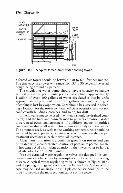
P1: GDZ/FFX P2: GDZ/FFX QC: GDZ/FFX T1: GDZ
GB076-10 GB076-Miller-Sample July 15, 2004 4:32 Char Count= 0
276 Chapter 10
FAN
SPRAYHEADS
SPEEDREDUCER
SPRAYELIMINATORS
WATERDISTRIBUTION
SYSTEM
BAFFLES
Figure 10-3 A typical forced-draft, water-cooling tower.
a forced-air tower should be between 250 to 600 feet per minute.The efficiency of a tower will range from 35 to 90 percent, the usualdesign being around 67 percent.
The circulating water pump should have a capacity to handleat least 5 gallons per minute per ton of cooling. Approximately1 gallon of every 100 gallons of water circulated is lost by drift;approximately 1 gallon of every 1000 gallons circulated per degreeof cooling is lost by evaporation. Care should be exercised in select-ing a location for the tower to obtain efficient operation and yet notconflict with buildings, cornices, and so on, for drift.
If the tower is not to be used in winter, it should be drained com-pletely and the lines and basin cleaned to prevent corrosion. Watertowers need occasional treatment of inhibitors against impuritiescontained in almost all water. This requires an analysis of the water.The amounts used, as well as the working temperatures, should beanalyzed by an experienced chemist who will prescribe the propertreatment necessary in each individual instance.
Algae moss formation is a common growth on towers and canbe treated with a concentrated solution of potassium permanganatein hot water. Add a sufficient quantity to the tower water to hold apinkish color for 15 to 20 minutes.
Pressure-actuated water-regulating valves are designed for con-densing units cooled either by atmospheric or forced-draft coolingtowers. A typical water-regulating valve is shown in Figure 10-4,and the piping arrangement is shown in Figure 10-5. Valves of thistype may be used on single- or multiple-condenser hookups to thetower to provide the most economical use of the tower.

P1: GDZ/FFX P2: GDZ/FFX QC: GDZ/FFX T1: GDZ
GB076-10 GB076-Miller-Sample July 15, 2004 4:32 Char Count= 0
Water-Cooling Systems 277
Figure 10-4 Three-way, pressure-regulating valve used in condensingunits cooled by either an atmospheric or forced-draft cooling tower.(Courtesy Penn Controls, Inc.)
AIROUT
TEMPERATURECONTROL
FAN
POWERSUPPLY
CONDENSERWATER
TO CONDENSER
WATER PUMP CONTROL BULBMAKEUP WATER VALVE
AIRIN
BAFFLES
SPRAYHEADS
SPRAYELIMINATORS
Figure 10-5 Typical cooling-tower control equipped with forced draft.

P1: GDZ/FFX P2: GDZ/FFX QC: GDZ/FFX T1: GDZ
GB076-10 GB076-Miller-Sample July 15, 2004 4:32 Char Count= 0
278 Chapter 10
In operation, low refrigerant head pressure may be the resultof low tower-water temperature, which causes the cooling abilityof the refrigeration system to fall off rapidly. The valve senses thecompressor head pressure and allows cooling water to flow to thecondenser, to bypass the condenser, or to flow to both condenserand bypass line to maintain correct refrigerant-head pressures. Withthe correct valve size and adequate pump capacity, the three-wayvalve will maintain refrigerant condensing temperatures between90◦F and 105◦F, with cooling-tower water temperatures of 85◦Fto 40◦F. Figure 10-6 shows a water-temperature safety-control unitwith time-delay switch.
Figure 10-6 Exterior view ofwater-temperature safetycontrol with built-in time-delayswitch. (Courtesy Penn Controls, Inc.)
The three-way valve permits water flow to the tower throughthe bypass line, even though the condenser does not require cool-ing. This provides an adequate head of water at the tower at alltimes so that the tower can operate efficiently with a minimum ofmaintenance on nozzles and wet surfaces.
Cooling PondsThe cooling pond is usually resorted to when location of the plantis such that a natural body of water is not available nearby. Here,the water is cooled by being forced into surface contact with the air,and the amount of cooling will depend on the relative temperatureof the air and the humidity.
Any available pond or lake may be used as a means of coolingrecirculated water without the use of sprays, provided it is largeenough for the purpose. The heated water should be delivered asfar from the suction connections as possible. Since the cooled watertends to sink because of its greater density, the best results will beachieved where the suction is applied at the bottom of the pond.
P1: GDZ/FFX P2: GDZ/FFX QC: GDZ/FFX T1: GDZ
GB076-10 GB076-Miller-Sample July 15, 2004 4:32 Char Count= 0
Water-Cooling Systems 279
Spray-Cooling PondsThe spray-cooling pond differs from the cooling pond discussedpreviously in that a means is introduced to accelerate the coolingeffect. It consists essentially of properly designed sprays or nozzlesthat break the water into fine drops. The drops must fall back intothe pond. The drops should not be carried away. The number ofnozzles required depends on the size of the pond and the waterrequirement of the plant. In average practice, the nozzles are locatedfrom 3 to 8 feet above the water level, and in horizontal rows offrom 10 to 16 inches apart.
The pressure at the inlet to the spray system may be from 5 to12 psi. As in the cooling pond, the final temperature of the waterdepends on air temperature and humidity. In most cases, however, areduction of water temperature of from 10◦ to 15◦ may be obtainedwith a single spraying.
New DevelopmentsAll-metal towers with housing, fans, fill, piping, and structural mem-bers made of galvanized or stainless steel are now being built.One factor in this change is that some local building codes are be-coming more restrictive with respect to fire safety; another is lowmaintenance.
Engineers are beginning to specify towers (such as all steel or allmetal) that are less subject to deterioration caused by environmentalconditions. Already, galvanized steel towers have made inroads intothe air-conditioning and refrigeration market. Stainless-steel towersare being specified in New York City, northern New Jersey, and LosAngeles, primarily because of a polluted atmosphere that can lead toearly deterioration of nonmetallic towers and, in some cases, metals.
Figure 10-7 shows a no-fans design for a cooling tower. Largequantities of air are drawn into the tower by cooling water as it isinjected through spray nozzles at one end of a venturi plenum. Nofans are needed. Effective mixing of air and water in the plenumpermits evaporative heat transfer to take place without the fill re-quired in conventional towers. The cooled water falls into the sumpand is pumped through a cooling-water circuit to return for anothercycle. The name applied to this design is Baltimore Air-coil. In 1981,towers rated at 10 to 640 tons with 30 to 1920 gallons per minutewere standard. The nozzle-clogging problems have been minimizedby using prestrainers in the high-pressure flow. There are no movingparts in the tower. This results in very low maintenance costs.
Air-cooled condensers are reaching 1000 tons in capacity. Aircoolers and air condensers are quite attractive for use in refineries

P1: GDZ/FFX P2: GDZ/FFX QC: GDZ/FFX T1: GDZ
GB076-10 GB076-Miller-Sample July 15, 2004 4:32 Char Count= 0
280 Chapter 10
AIR
N0ZZLES AIR/WATER MIXTURE
WATER-LEVEL ADJUSTMENT
ELIMINATORS
SUMP
DISCHARGE COWL
Figure 10-7 Newer, no-fans tower design.
and natural-gas compressor stations. They are also used for coolingin industry, as well as for commercial air-conditioning purposes.Figure 10-7 shows how the air-cooled condensers are used in a circuitsystem that is completely closed. These are very popular where thereis little or no water supply.
Cooling-Unit PipingDuring the passage of refrigerant through the piping system, a pres-sure drop takes place similar to that which occurs in the suctionand discharge valves of the compressor. The pressure drop throughthe piping between the compressor and condenser requires a higherpressure inside the compressor during discharge than in the con-denser. Unless the liquid is subcooled, pressure losses in the liquidline between condenser, receiver, and expansion valve may causeflashing of the liquid refrigerant with consequent faulty expansion-valve operation.
In selecting refrigerant piping, frictional losses should be kept toa minimum. Piping should be selected that will give the smallestpossible losses. It is necessary to consider the optimum sizes withrespect to economics, friction losses, and oil return.
Pressure-drop consideration in liquid lines, however, is not ascritical as with suction and discharge lines. The important things toremember are that the pressure drop should not be so excessive as tocause gas formation in the liquid line or insufficient liquid pressure

P1: GDZ/FFX P2: GDZ/FFX QC: GDZ/FFX T1: GDZ
GB076-10 GB076-Miller-Sample July 15, 2004 4:32 Char Count= 0
Water-Cooling Systems 281
at the liquid-feed device. A system should normally be designed sothat the pressure drop in the liquid line, due to friction, is not greaterthan that corresponding to about a 1◦ to 2◦ change in saturationtemperature. Friction pressure drops in the liquid line include ac-cessories (such as solenoid valves, strainer-driers, and hand valves),as well as the actual pipe and fittings from the receiver outlet to therefrigerant-feed device at the evaporator.
Pressure drop in the suction line means a loss in system capacity,because it forces the compressor to operate at a lower suction pres-sure to maintain the desired evaporating temperature in the coil. Itis usually standard practice to size the suction line to have a pressuredrop caused by friction not any greater than the equivalent of abouta 1◦ to 2◦ change in saturation temperature.
Where a reduction in pipe size is necessary to provide sufficientgas velocity to entrain oil up vertical risers at partial loads, greaterpressure drops will be imposed at full load. These can usually becompensated for by over-sizing the horizontal and down comer linesto keep the total pressure drop within the desired limit. It is impor-tant to minimize the pressure loss in discharge lines because lossesin these lines increase the required compressor horsepower per tonof refrigeration, and decrease the compressor capacity.
A refrigerant piping system should be designed and operated toaccomplish the following:
� Ensure proper refrigerant feed to evaporators� Provide practical refrigerant-line sizes without excessive pres-
sure drop� Prevent excessive amounts of lubricating oil from being
trapped in any part of the system� Protect the compressor from loss of lubricating oil at all times� Prevent liquid refrigerant from entering the compressor during
either operating or idle time� Maintain a clean and dry system
Liquid LinesRefrigerants for these units will be required to be ozone-layerdamage-free in the near future. In the meantime, there are manyolder units still out there with more service requirements as theyage.
Liquid lines present no particular design problem. Refrigerationoil is sufficiently miscible with Freon-12 and Freon-22 in the liquid

P1: GDZ/FFX P2: GDZ/FFX QC: GDZ/FFX T1: GDZ
GB076-10 GB076-Miller-Sample July 15, 2004 4:32 Char Count= 0
282 Chapter 10
form to ensure adequate mixing and positive oil return. Low liquidvelocities and traps in the line do not pose oil-return problems. Indesigning a liquid line, however, it must be recognized that it is de-sirable to have slightly subcooled liquid reach the liquid-feed deviceat a sufficiently high pressure for proper operation of the device.
Where liquid subcooling is required, this is usually accomplishedin one or both of the following methods: use of a liquid-suctionheat interchanger or use of liquid subcooling coils in evaporativecondensers. The determination of how much liquid subcooling isrequired to offset friction and static head losses is quite simple. Atnormal liquid temperatures, the static pressure loss caused by eleva-tion at the top of a liquid lift is equal to 1 psi for every 1.8 feet forFreon-12, and 2 feet for Freon-22.
Suction LinesSuction lines are the most critical from a design and constructionstandpoint (see Figure 10-8). Several important aspects must be con-sidered in the design of refrigerant suction lines:� The suction line should be sized for a practical pressure drop
at full load.� The suction line should be designed to return oil from the
evaporator to the compressor under minimum load conditions.� The suction lines should be designed to prevent liquid from
draining into the compressor during shutdown.� The suction line should be designed so that oil from an active
evaporator does not drain into an idle evaporator.
EVAPORATOR
EVAPORATOREVAPORATOR
SUCTION LINETO
COMPRESSORPITCH DOWN
TO VALVE BULB
Figure 10-8 Typical piping from evaporators located above and belowcommon suction line.

P1: GDZ/FFX P2: GDZ/FFX QC: GDZ/FFX T1: GDZ
GB076-10 GB076-Miller-Sample July 15, 2004 4:32 Char Count= 0
Water-Cooling Systems 283
Oil CirculationLubricating oil is lost from reciprocating compressors during normaloperation because these compressors are designed so that the pistonsand piston rings ride on a film of oil while traversing the cylinder.A small quantity of this oil is continuously pushed on through thecylinders and out with the discharge gas. Since it is inevitable thatoil will leave the compressor with the refrigerant, means must beprovided for in systems using Freon-12 and Freon-22 to return thisoil at the same rate at which it leaves.
Oil that leaves the compressor reaches the condenser and therebecomes dissolved with the liquid refrigerant. In this condition, itreadily passes through the liquid supply lines to the evaporators. Inthe evaporator, however, a distillation process occurs, and there isalmost complete separation of the oil and refrigerant. Very little oilcan remain in the relatively cold and less dense refrigerant vaporat the temperature and pressure corresponding to its evaporatingcondition. Therefore, oil that is separated in the evaporator can bereturned to the compressor only by gravity or entrainment with thereturning gas.
Suction risers must be sized for minimum system capacity. It isextremely important that oil be returned to the compressor at the op-erating condition corresponding to the minimum displacement andminimum suction temperature at which the compressor will oper-ate. For compressors with capacity control, the minimum capacityis represented by the lowest capacity at which the compressor canoperate. In the case of multiple compressors with capacity control,it is important that the minimum capacity is the lowest at which thelast operating compressor can run.
Discharge LinesThe design of discharge (hot gas) lines with self-contained con-densing units does not present any problem, because these are usu-ally factory-assembled. In the case of remotely located condensers,the essential element of hot-gas–line design should include thefollowing:� The hot-gas line should be sized for a practical pressure drop.� The hot-gas line should be designed to avoid trapping oil at
partial-load operation.� The hot-gas line should be designed to prevent refrigerant from
condensing and draining back to the head of the compressor.� Connections of multiple compressors to a common hot-gas
line should be carefully chosen and designed.

P1: GDZ/FFX P2: GDZ/FFX QC: GDZ/FFX T1: GDZ
GB076-10 GB076-Miller-Sample July 15, 2004 4:32 Char Count= 0
284 Chapter 10
� The lines should not develop excessive noise and vibrationas the result of hot-gas pulsations or compressor vibration(Figure 10-9).
GAS CONNECTION AT TOP OF CONDENSER
CHECK VALVE
HOT GAS LINE
CONDENSER(EVAPORATIVE OR WATER COOLED)
LOOP TO FLOOR
COMPRESSOR
COMPRESSOR BASE
Figure 10-9 Hot-gas loop connections showing piping arrangementto prevent liquid and oil from draining back to the compressor head(single compressor).
Even though a low loss is desired in hot-gas lines, they should notbe oversized to the extent that gas velocities are reduced to a pointwhere the refrigerant will not be able to carry along any entrainedoil. In the usual application, this will not be a problem in hot-gaslines. In the case of multiple compressors with capacity control, itis wise to make sure any hot-gas risers will carry oil along at allpossible loadings, as shown in Figure 10-10.
Refrigerant-Piping ArrangementThe refrigerant piping should be arranged so that normal inspec-tion and servicing of the compressor and other equipment will notbe hindered. To minimize tubing, refrigerant and pressure drop linesshould be as small as possible. Sufficient flexibility, however, shouldbe provided to absorb compressor vibration. In locations where

P1: GDZ/FFX P2: GDZ/FFX QC: GDZ/FFX T1: GDZ
GB076-10 GB076-Miller-Sample July 15, 2004 4:32 Char Count= 0
Water-Cooling Systems 285
Connect asclose as possible.
VAPOR EQUALIZERLINE
If condenser is locatedbelow compressor
discharge line, traps(as shown) are not
required.
Valve stem to be locatedin a horizontal
position.
Oil equalizer line locatedat floor level. Compressors
must be on same level.
Vertical riser of suction lineto be centrally located with each
suction line exactly the samelength.
Figure 10-10 Piping connections for suction and hot-gas headers(multiple compressors).
copper tubing will be exposed to mechanical injury, the tubingshould be enclosed in rigid or flexible conduit. In addition, pipingshould be run so as not to interfere with passages, obstruct head-room, or affect the opening of windows or doors.
Piping SupportsRod-type hangers, perforated metal strips, or wall brackets that arecommercially available are satisfactory and provide a simple meansof supporting horizontal pipe runs. On vertical pipe runs, the pipingweight may be supported with riser clamps bearing on structuralmembers of the building, or by means of a platform at the bottomof the riser.
Supports should be strong enough to support any load caused bythermal expansion or contraction of the pipe so that stresses willnot be placed on the equipment connected to the piping. In some

P1: GDZ/FFX P2: GDZ/FFX QC: GDZ/FFX T1: GDZ
GB076-10 GB076-Miller-Sample July 15, 2004 4:32 Char Count= 0
286 Chapter 10
cases, it may be necessary to provide some form of vibration iso-lation between pipe and support, thereby preventing objectionablevibrations that may be transmitted through the structure.
Piping InsulationInsulation of refrigeration pipes serves a two-fold purpose: to pre-vent moisture condensation and to prevent heat gain from the sur-rounding air. The desirable properties of pipe insulation are asfollows:� It should have a low efficiency of heat transmission.� It should be easy to apply and have a high degree of perma-
nency.� It should be readily protected against air and moisture
infiltration.� It should have a reasonable installation cost.
All suction lines should be insulated to prevent moisture conden-sation and heat gain. Ordinarily, liquid lines do not require insula-tion on installations where the suction and liquid lines are clampedtogether, but the two lines may be insulated as a unit. It is also ad-visable to insulate the liquid line when it passes through an area of
SPACE FILLEDWITH FITTING FILLER
SPACE FILLEDWITH FITTING FILLER
SPACE FILLEDWITH FITTING FILLER
SPACE FILLEDWITH FITTING FILLER
CUT ON THIS LINE
Figure 10-11 Various fittings insulated with cork covering.

P1: GDZ/FFX P2: GDZ/FFX QC: GDZ/FFX T1: GDZ
GB076-10 GB076-Miller-Sample July 15, 2004 4:32 Char Count= 0
Water-Cooling Systems 287
higher temperature to minimize heat gain. Normally hot-gas linesare not insulated. They should be, however, if the heat dissipatedwould be objectionable or where there is a possibility of people be-ing burned by the pipe. In the latter case, it is not essential to provideinsulation with a tight vapor seal since there is no problem of mois-ture condensation. Figure 10-11 shows various insulated fittings forpipes.
Insulation covering lines on which moisture can condense or linessubjected to outside conditions must be vapor-sealed to prevent anymoisture travel through the insulation or condensation in the in-sulation. Many commercially available types are provided with anintegral waterproof jacket. On these and other types, it is essentialthat the manufacturer’s recommendations regarding sealing be fol-lowed carefully. Although all joints and fittings should be covered,it is not advisable to do so until the system has been thoroughlyleak-tested and operated for some time.
SummaryWater-cooled condensing units require an unfailing supply of suit-able water. Condenser water may be obtained from city mains,rivers, lakes, wells, or by means of recirculating water towers.
Water towers are usually applicable in localities having excessivewater rates or where sufficient quantities of cold water are not avail-able and evaporative condensers are not suitable. In a cooling tower,approximately 1 gal per 100 gal of water circulated is lost by drift.Approximately 1 gal per 1000 gal circulated per degree of coolingis lost by evaporation.
Algae moss formation is common growth on towers and can betreated with a concentrated solution of potassium permanganate inhot water.
Cooling ponds are usually resorted to when location of the planis such that a natural body of water is not available nearby.
Pressure drop in the suction line means a loss in the system capac-ity, because it forces the compressor to operate at a lower suctionpressure to maintain the desired evaporating temperature in the coil.
Suction lines are the most critical from a design and construc-tion standpoint. Several important aspects must be considered inthe design of refrigerant lines.
Lubricating oil is lost from reciprocating compressors during nor-mal operation because these compressors are designed so that thepistons and piston rings ride on a film of oil while traversing thecylinder. Oil that leaves the compressor reaches the condenser andthere becomes dissolved with the liquid refrigerant.

P1: GDZ/FFX P2: GDZ/FFX QC: GDZ/FFX T1: GDZ
GB076-10 GB076-Miller-Sample July 15, 2004 4:32 Char Count= 0
288 Chapter 10
The design of discharge (hot-gas) lines with self-contained con-densing units does not present any problem since these are usuallyfactory-assembled.
The refrigerant piping should be arranged so that normal inspec-tion and servicing of the compressor and other equipment will notbe hindered.
Review Questions1. What are some of the problems associated with water-cooling
systems during the winter months?2. Where are water towers used?3. How does a water tower cool water or refrigerant?4. What should you do with a water tower if it is not used during
the winter?5. What is the most common growth on towers that needs treat-
ment?6. Where are pressure-actuated, water-regulating valves used?7. Why are cooling ponds used?8. How does the spray-cooling pond differ from the regular
cooling pond?9. What does a pressure drop in the suction line mean in the way
of capacity of a system?10. How is lubricating oil lost during normal operation of a com-
pressor?11. How must suction risers be designed?12. What is another name for the discharge line from a compres-
sor?13. How should the piping be arranged in the refrigeration system?14. What are the two purposes of piping insulation?15. Why should all suction lines be insulated?

P1: GDZ/FFX P2: GDZ/FFX QC: GDZ/FFX T1: GDZ
GB076-11 GB076-Miller-Sample July 15, 2004 16:41 Char Count= 0
Chapter 11Air-Conditioning ControlMethodsControls are an essential part of every air-conditioning installation.Some means must be provided for regulating the temperature andrelative humidity to maintain conditions that are comfortable tohuman beings, or that are required for industrial applications. Out-side temperatures and relative humidity are seldom constant forany length of time, and throughout the seasons, these atmosphericconditions fluctuate over a wide range. Thus, without controls, thetemperatures would be too low at times and too high at other times,while humidity would vary considerably. With such variable condi-tions, it is obvious that any installation would be unsatisfactory toboth the customer and the manufacturer.
Economy of operation is also a very important factor, since it willnot be necessary to operate the equipment continually throughoutthe season. Therefore, controls should be furnished to actuate thevarious operating devices to keep the cost of operation to a reason-able figure. In this connection, it should be clearly understood thatair-conditioning equipment is generally specified to cover the aver-age maximum demand made upon it, and that this maximum doesnot exist except for a relatively few days during the year.
Types of Air-Conditioning ControlsThere are three general types of air-conditioning controls: manual,automatic, and semiautomatic.
Manual ControlManual control requires personal attention and regulation at fre-quent intervals, especially when the load varies continually. Even ifthe unit is in operation only at certain times of the day, inside andoutside conditions may vary so much that constant changes in ad-justment are necessary. A manual control may be an ordinary snapor knife switch or similar switch, which must be operated by handwhen it is desired to start or stop the unit.
While giving temperature and humidity regulation for a given setof conditions, this type of control will not provide the most desirableregulation because of fluctuating demands. Constant attention is re-quired by the operator to maintain the predetermined conditions asclosely as humanly possible, with the result that cost of operation isusually found to be excessive. If a manual control is provided, the
289
P1: GDZ/FFX P2: GDZ/FFX QC: GDZ/FFX T1: GDZ
GB076-11 GB076-Miller-Sample July 15, 2004 16:41 Char Count= 0
290 Chapter 11
user will permit the unit to operate until the room is too cold, or willforget to start the machine until the room has reached an uncom-fortable temperature. In either case, the user will not be satisfied. Itis, therefore, always advisable to install an automatic control.
Automatic ControlA completely automatic installation will meet a varying load almostinstantly. This type of control involves the use of a large number ofinstruments (such as time clocks, thermostats, humidity controllers,and automatic dampers) operated by either electricity or compressedair. Automatic controls provide all the features that are consideredmost desirable for temperature and humidity regulation, as well asfor economy of operation. The operator or owner is relieved ofall responsibility for maintaining the predetermined conditions, andoperating costs will be kept at a minimum.
As an example, consider an office being cooled by a unit con-ditioner. The unit is specified to maintain comfortable conditionsduring the hottest days of the summer, and it must furnish com-fortable conditions on mild days in the spring and fall. Unless anautomatic control is used, the office will get too cold on mild days,and a complaint of unsatisfactory operation will be registered.
Semiautomatic ControlThe semiautomatic control system differs from the manual and theautomatic systems primarily in the number of control devices re-quired. For example, a differential thermostat will be entirely sat-isfactory for temperature regulation in most cases. Time clocks arealso very desirable on installations where definite shutdown periodsare required. The fresh-air intake from outdoors should always beequipped with adjustable louvers so that the maximum amount ofair can be regulated for both summer cooling and winter heating.
It is desirable on any job below 25 tons to keep the control sys-tem as simple and free from service liabilities as possible. On largetheater or building applications, the expenditure of a considerableamount for control equipment for thermostatic or manual controlshould constitute the extent of the control system. This may includeprovisions for manually controlled ventilation and time-clock oper-ation. If the additional expense is warranted, the job can be equippedwith automatic humidity controls.
Basic Control TypesThe various controls as applied to air-conditioning systems con-sist of different devices for maintaining temperature, humidity, and

P1: GDZ/FFX P2: GDZ/FFX QC: GDZ/FFX T1: GDZ
GB076-11 GB076-Miller-Sample July 15, 2004 16:41 Char Count= 0
Air-Conditioning Control Methods 291
pressure within certain predetermined limits. These devices may beclassified broadly as temperature-control devices, humidity-controldevices, and pressure-control devices.
Residence-type control equipment may range from automaticregulation of heating plants to control of complete year-round airconditioning. Various actuating devices sensitive to changes in con-dition include the following: thermostats, hygrostats, and pressureregulators.
The various residence heating controls employed depend on thefuel supply used for the appliance, which may be classified as coal-heated, oil-heated, gas-heated, or electrically heated.
All the foregoing includes a room thermostat as part of the con-trol. Various kinds of thermostats in common use are the room,duct, and immersion types.
Room ThermostatsBy definition, a room thermostat is an automatic device for regu-lating temperature by opening or closing a damper or other deviceof a heating appliance (such as a heating furnace or electric heatelement). Thermostats are based on the principles of expansion andcontraction of metals caused by temperature changes. They consistessentially of a loop or coil made up of a bimetal strip (such asbrass and steel) securely fastened together, having one end fixed andthe other attached to a pointer as shown in Figure 11-1. As room
Cool
Off
Heat OnFan
Auto
6070 80 90
60 70 80 90On Heat
OffCool
FanAuto
-60-70-80-90-
Figure 11-1 Two types of wall mounted room thermostats.

P1: GDZ/FFX P2: GDZ/FFX QC: GDZ/FFX T1: GDZ
GB076-11 GB076-Miller-Sample July 15, 2004 16:41 Char Count= 0
292 Chapter 11
temperature falls below a certain value, the pointer bends towardone of the contacts until it closes an electric circuit, which, in turn,energizes a furnace-control device. This operation will supply ad-ditional heat to the room. When the temperature rises above thatdesired the pointer moves toward the other contact, which, due toits electrical circuit device, acts to reduce the heat produced. Figure11-2 shows a microprocessor used for heating and air-conditioningcontrol in a home, and Figure 11-3 shows the electrical circuitry fora home heat-cool thermostat.
LEAVEMON
ENRO SAV SYSTEM
SETPROGRAMDAYTIME
WAKEDAY
RUNPROGRAM
PERIOD TIME
TEMPERATUREPRESENTSETTING
SKIPNEXT
PERIOD
CHANGETO LASTPERIOD
LEAVEAHEAD WARMER
COOLERBACKSLEEP RETURNHOLDTEMP
SET WARMCOOL
FAN ON AUTOHEAT OFF COOL AUTO
°ΑΜ:.
Figure 11-2 Microprocessor used for air-conditioning and furnacecontrol in a home.
Thermostats utilize either the differential expansion of solids, liq-uids, or gases subject to heat, or the thermopile principle. A fixed-temperature thermostat operates at predetermined fixed tempera-tures, whereas a rate-of-rise thermostat operates when the rate ofincrease in temperature exceeds a predetermined amount. Roomthermostats are usually mounted on the wall of the room or spacewhere the temperature is to be controlled. In locating the room ther-mostat, the following rules should be observed:
� The thermostat should always be on an inside partition, neveron an outside wall.� Do not mount the instrument on a part of the wall that has
steam or hot water pipes or warm air ducts behind it.

P1: GDZ/FFX P2: GDZ/FFX QC: GDZ/FFX T1: GDZ
GB076-11 GB076-Miller-Sample July 15, 2004 16:41 Char Count= 0
Air-Conditioning Control Methods 293
AUTO ON
FAN
SWITCH ACTION ON TEMPERATURE RISE
ADJUSTABLE HEATANTICIPATION
COLD
ANTICIPATION
24-V SUPPLY HEAT
EXACTTERMINALLOCATION
COOLFAN
SYSTEM: HEATING AND COOLING SWITCHING: FAN-ON/AUTO
FAN SWITCH
ON AUTO
SUB-BASE UNIT
THERMOSTAT ELEMENT
Figure 11-3 Electrical circuitry for a home heat-cool thermostat.
� The location should be such that direct sunshine or fireplaceradiation cannot strike the thermostat.� Be careful that the spot selected is not likely to have a floor
lamp near it or a table lamp under it.� Do not locate it near an outside door or a radiator, or where
warm air from a supply grille can strike it.� Do not locate it where heat from kitchen appliances can affect
it. Do not locate it on a wall that has a cold unused room onthe other side.� After a thermostat has been mounted, it is wise to fill the stud
space behind the instrument with insulating material to pre-vent any circulation of cold air. Furthermore, the hole behindthe thermostat for the wires should be sealed so that air cannotemerge from the stud space and blow across the thermostat
P1: GDZ/FFX P2: GDZ/FFX QC: GDZ/FFX T1: GDZ
GB076-11 GB076-Miller-Sample July 15, 2004 16:41 Char Count= 0
294 Chapter 11
element. It is quite common to find considerable air motionthrough this hole caused by a chimney effect in the studspace.
Remember that the thermostat location has nothing to do withthe heat balance of the various rooms. For example, if one room runscold, it does not help to move the thermostat to that room. True,placing the thermostat there will make the room warm, but the otherrooms will be overheated. The same result could be achieved at theoriginal location by setting the thermostat to a higher temperature.All instances of certain rooms being too hot or too cold must becorrected by changing the heat input to that room or the heat lossfrom it, not by moving the thermostat.
Twin-Type ThermostatsThe so-called night-and-day thermostat controls the heating or cool-ing source to maintain either of two selected temperatures. In prin-ciple, this is an assembly of two thermostats mounted on a singlebase with one cover. The electric clock can be set to throw the tem-perature control from one thermostat for the daytime temperaturesto the other for nighttime temperatures at a predetermined time set-ting on the clock. This conveniently permits a lower temperature atnight and normal temperature during the day.
Modern heating thermostats are built to incorporate a heat level-ing, or heat-anticipation device. A heating coil consisting of a high-resistance unit drawing very low current is automatically connectedin the thermostat circuit. When the thermostat contacts close, it callsfor heat (see Figure 11-4). The heat-anticipation feature may be de-scribed as follows: After the burner (or stoker, as the case may be)has been in operation a short time, the heating coil warms up slightly,which, in turn, has a warming effect on the thermostat mechanism.This causes the contacts to open in anticipation of the heat that hasbeen generated in the boiler or furnace, but has not yet reached theroom.
Duct ThermostatsA duct thermostat is provided with suitable fittings for installationin heating or air-conditioning ducts. The insertion-type is providedwith a rigid bulb and is arranged so that the temperature-responsiveelement or bulb extends through the wall of the duct. The remotebulb-type thermostat is arranged so that the bulb and instrumenthead are connected by means of a flexible tube of the desiredlength. In this arrangement, the bulb is inserted in the duct, and thehead is located where it is readily accessible for adjustment andinspection.
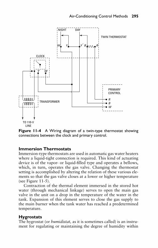
P1: GDZ/FFX P2: GDZ/FFX QC: GDZ/FFX T1: GDZ
GB076-11 GB076-Miller-Sample July 15, 2004 16:41 Char Count= 0
Air-Conditioning Control Methods 295
Figure 11-4 A Wiring diagram of a twin-type thermostat showingconnections between the clock and primary control.
Immersion ThermostatsImmersion-type thermostats are used in automatic gas water heaterswhere a liquid-tight connection is required. This kind of actuatingdevice is of the vapor- or liquid-filled type and operates a bellows,which, in turn, operates the gas valve. Changing the thermostatsetting is accomplished by altering the relation of these various ele-ments so that the gas valve closes at a lower or higher temperature(see Figure 11-5).
Contraction of the thermal element immersed in the stored hotwater (through mechanical linkage) serves to open the main gasvalve in the unit on a drop in the temperature of the water in thetank. Expansion of this element serves to close the gas supply tothe main burner when the tank water has reached a predeterminedtemperature.
HygrostatsThe hygrostat (or humidistat, as it is sometimes called) is an instru-ment for regulating or maintaining the degree of humidity within
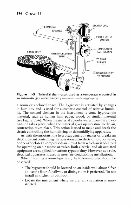
P1: GDZ/FFX P2: GDZ/FFX QC: GDZ/FFX T1: GDZ
GB076-11 GB076-Miller-Sample July 15, 2004 16:41 Char Count= 0
296 Chapter 11
THERMOSTAT
GAS INLET
GAS BURNER
STARTER DIAL
PILOT STARTERBUTTON
TEMPERATURE-SETTING DIAL
TO PILOT BURNER
MAIN GAS OUTLETTO BURNER
THERMAL ELEMENTTUBE
RUDD
02 770PILO
T
180
160
140 120100
80
60
Figure 11-5 Twin-dial thermostat used as a temperature control inan automatic gas water heater. (Courtesy Rudd Manufacturing Company.)
a room or enclosed space. The hygrostat is actuated by changesin humidity and is used for automatic control of relative humid-ity. The control element in the instrument is some hygroscopicmaterial, such as human hair, paper, wood, or similar material(see Figure 11-6). When the material absorbs water from the air, ex-pansion takes place; when the material gives up moisture to the air,contraction takes place. This action is used to make and break thecircuit controlling the humidifying or dehumidifying apparatus.
As with thermostats, the hygrostat generally makes or breaks anelectric circuit controlling the operation of an electric motor or valve,or opens or closes a compressed-air circuit from which air is obtainedfor operating an air motor or valve. Both electric- and air-actuatedequipment are supplied for various types of duty. However, as a rule,electrical apparatus is used in most air-conditioning installations.
When installing a room hygrostat, the following rules should beobserved:� The hygrostat should be located on an inside wall about 5 feet
above the floor. A hallway or dining room is preferred. Do notinstall in kitchen or bathroom.� Locate the instrument where natural air circulation is unre-
stricted.

P1: GDZ/FFX P2: GDZ/FFX QC: GDZ/FFX T1: GDZ
GB076-11 GB076-Miller-Sample July 15, 2004 16:41 Char Count= 0
Air-Conditioning Control Methods 297
ELEMENTADJUSTMENT
NUT
ELEMENTMOUNTING
PIN
ELEMENTMOUNTING PIN
HUMIDITY SETTINGPOINTER
HUMIDITYSCALE PLATE
HUMIDITYSETTING KNOB
HAIRELEMENT
SLIDE CONTACTFINGER
POTENTIO-METERCOIL
REGU
LATOR
TYPE7045
30 50 70
Figure 11-6 Typical hygrostat showing component parts with coverremoved. (Courtesy Honeywell, Inc.)
� Do not install the instrument where its operation might beaffected by lamps, sunlight, fireplace, registers, radiant heaters,radios, television, concealed air ducts, pipes, or other heat-producing appliances.
Pressure RegulatorsPressure regulators are manufactured in a number of different typesand sizes, and are designed to regulate the pressure of fluids, air,and gases. When designed for the regulation of a single pressure,they are classified as single-pressure regulators. When designed tomaintain a predetermined difference between two pressures, theyare termed dual-pressure regulators. A cutaway view is shown inFigure 11-7.
Limit ControlsA limit control is a device responsive to changes in pressure, tem-perature, or liquid level and is used to turn on, shut off, or throttle

P1: GDZ/FFX P2: GDZ/FFX QC: GDZ/FFX T1: GDZ
GB076-11 GB076-Miller-Sample July 15, 2004 16:41 Char Count= 0
298 Chapter 11
Figure 11-7 Interior view of a dual-function pressure control.(Courtesy Penn Controls, Inc.)
the fuel supply to a heating appliance. In steam-boiler operation,the limit control consists of a bellows arrangement, which, beingresponsive to boiler pressure, breaks an electric contact when thepressure exceeds a predetermined value, thus preventing additionalheat from being delivered to the boiler.
The limit control for a hot water boiler consists of an immersionthermostat inserted in a well of the boiler. The limit control stopsthe fuel supply when a predetermined water temperature has beenreached. In a warm-air heating system, a thermostat is inserted inthe furnace bonnet. The thermostat will cut off the heating sourcewhen a predetermined temperature has been attained.
Control ValvesControl valves are designed to control the flow of fluids and may beactuated in various ways (such as by thermostat or other controllingdevice). Depending on their construction, they may be classified as
P1: GDZ/FFX P2: GDZ/FFX QC: GDZ/FFX T1: GDZ
GB076-11 GB076-Miller-Sample July 15, 2004 16:41 Char Count= 0
Air-Conditioning Control Methods 299
normally open or normally closed. Depending on their application,they may be termed single-seated, double-seated, or three-way.
Single-seated valves are designed for tight shutoff. Double-seatedvalves are designed for applications where tight shutoff is not re-quired. Three-way valves are designed to operate between two ports,and to close one port as the other is opened.
DampersDampers are designed to control the flow of air or gases and may beoperated manually, by electricity, or by compressed air. Dependingon service conditions, they are known as the single or multi-bladetype. In large installations, dampers are motor-operated, the motorbeing actuated by a controlling device and connected to the bladesas required to give the desired movement.
Motors for operating dampers are provided when automatic reg-ulation of airflow is required in heating systems, ventilating ducts,air-conditioning systems, and air-conditioning supply ducts for zonecontrol. The motors are powered by electricity and controlled by theaction of a thermostatic element or by compressed air. They can beconnected to single- or multiple-louvered dampers. The damperscan be positioned by the motors as required and in accordance withindications from the governing device.
Two general classes of electrically operated motors are manu-factured: positive and reversing. Each class is divided into severaltypes, the positive motor being known as the two-position positive,four-position positive, and five-position positive, all unidirectionalin operation and with or without speed adjustment. The reversingmotor is known as the two-position, four-position, or five-positionmotor, which may be stopped, restarted in the original direction, orreversed at any point. These motors can be supplied with or withoutadjustable speed.
Standard three-wire thermostats or proportioning thermostatsare generally supplied for controlling the operation of the motors,although hygrostats and other control instruments can be used whenother types of regulation are required. Dampers can also be operatedby thermostatic elements, the expansion and contraction of a liquidor gas supplying the power required to actuate the dampers.
RelaysRelays are a necessary part of many control and pilot circuits. Bydefinition, a relay is a device that employs an auxiliary source ofenergy to amplify or convert the force of a controller into availableenergy at a valve or damper motor. Depending on their function in

P1: GDZ/FFX P2: GDZ/FFX QC: GDZ/FFX T1: GDZ
GB076-11 GB076-Miller-Sample July 15, 2004 16:41 Char Count= 0
300 Chapter 11
an air-conditioning system, relays may be classified as pneumatic,switching, or positioning.
A pneumatic relay (usually electrically operated) starts or stopsthe flow of air as required. A switching relay may be used to switchthe operation of a controlled device from one controller to another.A positioning relay may be directly connected to a damper motorlever or valve and is affected by valve or damper position.
Refrigerant Control DevicesTo control the flow of liquid refrigerant between the low and highside of a refrigeration system, some form of expansion device mustbe used. The various expansion and control devices required to ob-tain automatic control are as follows:� Automatic expansion valves� Thermostatic expansion valves� Low-side float valves� High-side float valves� Capillary tubes
Automatic Expansion ValvesThe function of an automatic expansion valve in a mechanical re-frigeration system is that of maintaining a constant pressure in theevaporator. Automatic expansion valves are usually employed ondirect-expansion refrigeration systems, but are not satisfactory inair conditioning because of load fluctuations. Figure 11-8 shows atypical expansion valve.
Thermostatic Expansion ValvesThe thermostatic expansion valve is designed to meter the flow ofrefrigerant into the evaporator in exact proportion to the rate ofevaporation of the refrigerant in the evaporator, thus preventing thereturn of liquid refrigerant to the compressor. By being responsiveto the temperature of the refrigerant gas leaving the evaporator andthe pressure in the evaporator, the thermostatic expansion valve cancontrol the refrigerant gas leaving the evaporator at a predeterminedsuperheat.
Figure 11-9 shows the construction of a thermostatic expan-sion valve. In construction, it is similar to the automatic expan-sion valve except that it has, in addition, a thermostatic element.This thermostatic element is charged with a volatile substance(usually a refrigerant, the same as that used in the refrigeration

P1: GDZ/FFX P2: GDZ/FFX QC: GDZ/FFX T1: GDZ
GB076-11 GB076-Miller-Sample July 15, 2004 16:41 Char Count= 0
Air-Conditioning Control Methods 301
INLET
STRAINER
SPRING
SPRING
MANUALADJUSTMENT
CHECK BALL
SEAT
OUTLET
PUSH ROD
VENT TUBE
BELLOWSDIAPHRAGM
Figure 11-8 Sectional viewof an automatic expansionvalve. (Courtesy Automatic Products, Inc.)
system in which the valve is connected). It functions according tothe pressure-temperature relationship and is connected (clamped) tothe evaporator suction line of the evaporator. It is also connectedto the bellows-operating diaphragm of the valve by a small sealedtube.
Its operation is governed by temperature. Thus, a rise in theevaporator temperature will increase the temperature of the evapo-rated gas passing through the suction line to which the thermostaticexpansion-valve bulb is clamped. The bulb absorbs heat. Since itscharge reacts in accordance with pressure-temperature relations, thepressure tending to open the valve needle is increased, and it opensproportionately.
Briefly, the greater the evaporator gas temperature increases inthe evaporator, the wider the valve opens, and vice versa. The widerthe valve opens, the greater is the percentage of coil flooding, whichimproves heat transfer and also causes the compressor to operateat a higher average suction pressure. Hence, the compressor capac-ity may be somewhat increased, which increases the overall systemcapacity.

P1: GDZ/FFX P2: GDZ/FFX QC: GDZ/FFX T1: GDZ
GB076-11 GB076-Miller-Sample July 15, 2004 16:41 Char Count= 0
302 Chapter 11
Figure 11-9 Sectional view of a typical thermostatic expansion valve.(Courtesy American Standard Controls.)
Sizing of Thermostatic Expansion ValvesThe sizing of thermostatic expansion valves should be done care-fully to avoid the evils of being undersized at full load and ex-cessively oversized at partial load. The refrigerant pressure drops

P1: GDZ/FFX P2: GDZ/FFX QC: GDZ/FFX T1: GDZ
GB076-11 GB076-Miller-Sample July 15, 2004 16:41 Char Count= 0
Air-Conditioning Control Methods 303
through the system (distributor, coil condenser, and refrigerant linesincluding liquid lifts) must be properly evaluated to arrive at thecorrect pressure drop available across the valve on which to basethe selection. Variations in condensing pressure during the periodof refrigeration requirements have a very important bearing on thepressure available across the valve, and hence on its capacity.
Occasionally, valves turn out to be undersized because of eitherunexpected flash gas in the liquid line, liquid lifts that were not takeninto consideration, or condensing temperatures below design. Moreoften, however, they turn out to be oversized because of one or moreof the following reasons:� Selections on the high side are overconservative.� Some manufacturers’ valves are underrated.� The pressure-drop available across the valve is much higher
than was considered in the selection of the valve, or (morelikely) it was not considered at all. This frequently happens onair-cooled condensing and low-temperature applications.� Sufficient increments in sizes are not available for a close se-
lection in all cases.� The refrigeration load was grossly overestimated.
Oversized thermostatic expansion valves do not control as wellat full-system capacity as properly sized valves and become pro-gressively worse as the coil load decreases. This results in a cyclingcondition of alternate flooding and starving of the coil because thevalve is attempting to throttle at a capacity below its capabilities,causing difficulties such as periodic flooding of liquid back to thecompressor and wide variations in air temperature leaving the coil.
Capacity reduction available in most compressors further aggra-vates this problem and necessitates closer selection of expansionvalves to match realistic loads. In systems having multiple coils, asolenoid valve can be located in the liquid line feeding each evap-orator (or group of evaporators) to be individually closed off ascompressor capacity is reduced.
Low-Side Float ValvesLiquid-refrigerant control by means of low-side float valves consistsessentially of a ball float located in the receiver or the evaporatorfastened to the low-pressure side of the refrigeration system. Theball float is fastened to a lever arm, which is pivoted at a given pointand connected to a needle that seats at the valve opening. If thereis no liquid in the evaporator, the ball-lever arm rests on a stop and
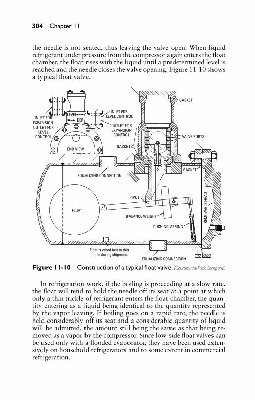
P1: GDZ/FFX P2: GDZ/FFX QC: GDZ/FFX T1: GDZ
GB076-11 GB076-Miller-Sample July 15, 2004 16:41 Char Count= 0
304 Chapter 11
the needle is not seated, thus leaving the valve open. When liquidrefrigerant under pressure from the compressor again enters the floatchamber, the float rises with the liquid until a predetermined level isreached and the needle closes the valve opening. Figure 11-10 showsa typical float valve.
GASKET
GASKETS
INLET FORLEVEL CONTROLINLET FOR
EXPANSION.OUTLET FOR
LEVELCONTROL
OUTLET FOREXPANSION
CONTROL
GASKET
PIVOT
VALVE PORTS
BALANCE WEIGHT
CUSHING SPRING
REM
OVAB
LE H
EAD
FLOAT
EQUALIZING CONNECTION
END VIEW
LEVELEXP
EQUALIZING CONNECTION
Float is wired fast to thisnipple during shipment.
Figure 11-10 Construction of a typical float valve. (Courtesy the Frick Company.)
In refrigeration work, if the boiling is proceeding at a slow rate,the float will tend to hold the needle off its seat at a point at whichonly a thin trickle of refrigerant enters the float chamber, the quan-tity entering as a liquid being identical to the quantity representedby the vapor leaving. If boiling goes on a rapid rate, the needle isheld considerably off its seat and a considerable quantity of liquidwill be admitted, the amount still being the same as that being re-moved as a vapor by the compressor. Since low-side float valves canbe used only with a flooded evaporator, they have been used exten-sively on household refrigerators and to some extent in commercialrefrigeration.
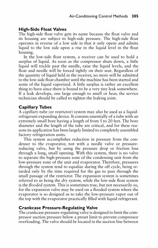
P1: GDZ/FFX P2: GDZ/FFX QC: GDZ/FFX T1: GDZ
GB076-11 GB076-Miller-Sample July 15, 2004 16:41 Char Count= 0
Air-Conditioning Control Methods 305
High-Side Float ValvesThe high-side float valve gets its name because the float valve andits housing are subject to high-side pressure. The high-side floatoperates in reverse of a low side in that it only opens and admitsliquid to the low side upon a rise in the liquid level in the floathousing.
In the low-side float system, a receiver can be used to hold asurplus of liquid. As soon as the compressor shuts down, a littleliquid will trickle past the needle, raise the liquid levels, and thefloat and needle will be forced tightly on their seat. Regardless ofthe quantity of liquid held in the receiver, no more will be admittedto the low-side float chamber until the machine has been started andsome of the liquid vaporized. A little surplus is rather an excellentthing to have since there is bound to be a very tiny leak somewhere.If a leak develops, one large enough to smell or hear, the servicetechnician should be called to tighten the leaking joint.
Capillary TubesA capillary-tube (or restrictor) system may also be used as a liquid-refrigerant expanding device. It consists essentially of a tube with anextremely small bore having a length of from 5 to 20 feet. The borediameter and the length of the tube are critical, and for these rea-sons its application has been largely limited to completely assembledfactory refrigeration units.
This system accomplishes reduction in pressure from the con-denser to the evaporator, not with a needle valve or pressure-reducing valve, but by using the pressure drop or friction lossthrough a long, small opening. With this system, there is no valveto separate the high-pressure zone of the condensing unit from thelow-pressure zone of the unit and evaporator. Therefore, pressuresthrough the system tend to equalize during the off cycle, being re-tarded only by the time required for the gas to pass through thesmall passage of the restrictor. The expansion system is sometimesreferred to as being the dry system, while the low-side float systemis the flooded system. This is sometimes true, but not necessarily so,for the expansion valve may be used on a flooded system where theevaporator is so designed as to take the low-pressure vapor out ofthe top with the evaporator practically filled with liquid refrigerant.
Crankcase Pressure-Regulating ValveThe crankcase pressure-regulating valve is designed to limit the com-pressor suction pressure below a preset limit to prevent compressoroverloading. The valve should be located in the suction line between
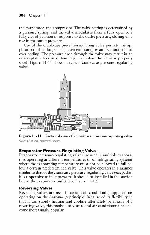
P1: GDZ/FFX P2: GDZ/FFX QC: GDZ/FFX T1: GDZ
GB076-11 GB076-Miller-Sample July 15, 2004 16:41 Char Count= 0
306 Chapter 11
the evaporator and compressor. The valve setting is determined bya pressure spring, and the valve modulates from a fully open to afully closed position in response to the outlet pressure, closing on arise in the outlet pressure.
Use of the crankcase pressure-regulating valve permits the ap-plication of a larger displacement compressor without motoroverloading. The pressure drop through the valve may result in anunacceptable loss in system capacity unless the valve is properlysized. Figure 11-11 shows a typical crankcase pressure-regulatingvalve.
Figure 11-11 Sectional view of a crankcase pressure-regulating valve.(Courtesy Controls Company of America.)
Evaporator Pressure-Regulating ValveEvaporator pressure-regulating valves are used in multiple evapora-tors operating at different temperatures or on refrigerating systemswhere the evaporating temperature must not be allowed to fall be-low a certain predetermined valve. This valve operates in a mannersimilar to that of the crankcase pressure-regulating valve except thatit is responsive to inlet pressure. It should be installed in the suctionline at the evaporator outlet (see Figure 11-12).
Reversing ValvesReversing valves are used in certain air-conditioning applicationsoperating on the heat-pump principle. Because of its flexibility inthat it can supply heating and cooling alternately by means of areversing valve, this method of year-round air conditioning has be-come increasingly popular.
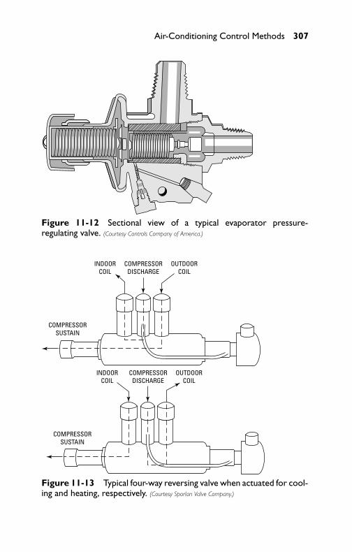
P1: GDZ/FFX P2: GDZ/FFX QC: GDZ/FFX T1: GDZ
GB076-11 GB076-Miller-Sample July 15, 2004 16:41 Char Count= 0
Air-Conditioning Control Methods 307
Figure 11-12 Sectional view of a typical evaporator pressure-regulating valve. (Courtesy Controls Company of America.)
COMPRESSORSUSTAIN
INDOORCOIL
COMPRESSORDISCHARGE
OUTDOORCOIL
COMPRESSORSUSTAIN
INDOORCOIL
COMPRESSORDISCHARGE
OUTDOORCOIL
Figure 11-13 Typical four-way reversing valve when actuated for cool-ing and heating, respectively. (Courtesy Sporlan Valve Company.)

P1: GDZ/FFX P2: GDZ/FFX QC: GDZ/FFX T1: GDZ
GB076-11 GB076-Miller-Sample July 15, 2004 16:41 Char Count= 0
308 Chapter 11
In operation, the four-way reversing valve (see Figure 11-13) willenable the evaporator and condenser function to be switched by achange in refrigerant flow, as desired, so that the indoor coil be-comes the evaporator for cooling purposes and the condenser forthat of heating. In this manner, the outdoor coil functions as a con-denser during the cooling cycle and as an evaporator during theheating cycle. The control of the valve is by means of a slide actionactuated by a solenoid. Thus, the connection from the compressorsuction and the discharge ports to the evaporator and condensercan be reversed to obtain either cooling or heating, as conditionsrequire.
SummaryControls are essential for air-conditioning systems. Some meansmust be provided for regulating the temperature and relative humid-ity to maintain conditions that are comfortable for human beingsor required for industrial applications.
The three general types of air-conditioning controls are manual,automatic, and semiautomatic.
Devices used to control temperature, humidity, and pressurewithin predetermined limits are classified broadly as temperature-control, humidity-control, and pressure-control. Thermostats, hy-grostats, and pressure regulators are sensing devices that work tocontrol the valves that control the refrigeration systems.
A limit control is a device responsive to changes in pressure, tem-perature, or liquid level, and is used to turn on (or throttle) the fuelsupply to a heating appliance.
Control valves are designed to control the flow of fluids and maybe actuated in various ways. They may be controlled by thermostatsor some other device. Valves are used to control the flow of refrig-erant. Single-seated valves are designed for tight shutoff. Double-seated valves are designed for applications where tight shutoff isnot required. Three-way valves are designed to operate betweentwo ports and to close one port as the other is opened.
Dampers are designed to control the flow of air or gases and maybe operated manually, by electricity, or by compressed air.
Relays are a necessary part of many control and pilot circuits. Arelay is a device that uses an auxiliary source of energy to amplifyor convert the force of a controller into available energy at a valveor damper motor.
An automatic expansion valve in a mechanical refrigerationsystem maintains a constant pressure in the evaporator. Auto-matic expansion valves are usually employed on direct-expansion

P1: GDZ/FFX P2: GDZ/FFX QC: GDZ/FFX T1: GDZ
GB076-11 GB076-Miller-Sample July 15, 2004 16:41 Char Count= 0
Air-Conditioning Control Methods 309
refrigeration systems. They are not suitable for use on air-conditioning systems due to load fluctuations.
The thermostatic expansion valve is designed to meter the flowof refrigerant into the evaporator in exact proportion to the rateof evaporation of the refrigerant in the evaporator. Thermostaticexpansion valves should be sized carefully to avoid the evils of beingundersized at full load and excessively oversized at partial load.
A capillary tube or restrictor system may also be used as a liquid-refrigerant expanding device. The restrictor or capillary-tube systemaccomplishes the reduction in pressure from the condenser to theevaporator, not with a needle valve or pressure-reducing valve, butby using the pressure drop or friction loss through a long, smallopening.
The crankcase pressure-regulating valve is designed to limit thesuction pressure below a preset limit to prevent compressor over-loading. Evaporator pressure-regulating valves are used in multipleevaporators operating at different temperatures or on refrigeratingsystems where the evaporating temperature must not be allowed tofall below a certain predetermined value. Reversing valves are usedin certain air-conditioning applications operating on the heat-pumpprinciple.
Review Questions1. Why are controls needed in an air-conditioning system?2. What is the term for the general classification of air-
conditioning controls?3. What are the three basic control types?4. What is a hygrostat?5. What are three types of thermostats in common use?6. Where are immersion thermostats used?7. What is a humidistat?8. Where do you use a limit control?9. Why are dampers necessary?
10. What is a relay?11. List five refrigerant-control devices.12. What is the purpose of a thermostatic expansion valve?13. What is a capillary tube?14. Where are crankcase pressure-regulating valves used?15. Where are evaporator pressure-regulating valves used?

P1: GDZ/FFX P2: GDZ/FFX QC: GDZ/FFX T1: GDZ
GB076-11 GB076-Miller-Sample July 15, 2004 16:41 Char Count= 0
310 Chapter 11
16. What is a reversing valve?17. Where is the reversing valve used?18. How does the four-way reversing valve operate?19. What are two types of pressure regulators?20. How does the restrictor reduce pressure from the condenser
to the evaporator?
P1: GDZ/FFX P2: GDZ/FFX QC: GDZ/FFX T1: GDZ
GB076-12 GB076-Miller-Sample July 15, 2004 17:47 Char Count= 0
Chapter 12Weather Data and DesignConditionsThis chapter includes recommended design conditions (indoor andoutdoor) for summer and winter. Data on outdoor design conditionsare presented for more than 150 weather stations in the UnitedStates.
Indoor Design ConditionsThe indoor conditions to be maintained within a building are thedry-bulb temperature and relative humidity of the air at a breathingline 3 to 5 feet above the floor. The area should indicate averageconditions at that level and should not be affected by abnormal orunusual heat gains or losses from the interior or exterior.
Because it is difficult to maintain the mean radiant tempera-ture at the dry-bulb temperature in actual practice, the effect ofwarmer walls normally encountered during the cooling season willrequire a design condition lower than stated for optimum comfort.For this reason, the recommended 75◦F design dry-bulb temper-ature, slightly lower than the optimum range of 76.5 to 77.6◦F(with walls at room temperature), will partially compensate for thehigher mean radiant temperature normally found in comfort-coolingapplications.
During the heating season, the mean radiant temperature is nor-mally lower than air temperature (in some panel-heating instal-lations the mean radiant temperature could be higher than airtemperature), thereby suggesting a higher dry-bulb temperature than75◦F for comfort conditions. Because the type of clothing an individ-ual wears has an effect on the optimum indoor design temperature,and because the recent American Society of Heating, Refrigeration,and Air Conditioning Engineers (ASHRAE) comfort tests were per-formed with lightly clothed subjects, the overall effect is a recom-mended 75◦F design dry-bulb for both winter and summer. Whereunusual application conditions exist (such as large exposures of glassand inside partitions exposed to adjacent rooms of widely differenttemperatures), consideration should be given to adjustment of thedesign dry-bulb temperature to maintain comfort conditions. In nocase should the correction be made for mean radiant temperaturesoutside the range of 70◦F to 80◦F.
311
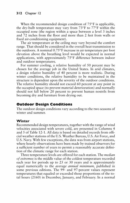
P1: GDZ/FFX P2: GDZ/FFX QC: GDZ/FFX T1: GDZ
GB076-12 GB076-Miller-Sample July 15, 2004 17:47 Char Count= 0
312 Chapter 12
When the recommended design condition of 75◦F is applicable,the dry-bulb temperature may vary from 73◦F to 77◦F within theoccupied zone (the region within a space between a level 3 inchesand 72 inches from the floor and more than 2 feet from walls orfixed air-conditioning equipment).
The air temperature at the ceiling may vary beyond the comfortrange. That should be considered in the overall heat transmission tothe outdoors. A nominal 0.75◦F increase in air temperature per footelevation above the breathing level would be expected in normalapplications, with approximately 75◦F difference between indoorand outdoor temperatures.
For summer cooling, a relative humidity of 50 percent may bechosen for the average job in the United States. In arid climates,a design relative humidity of 40 percent is more realistic. Duringwinter conditions, the relative humidity to be maintained in thestructure is dependent upon the severity of the outdoor conditions.The relative humidity should not exceed 60 percent at any point inthe occupied space (to prevent material deterioration) and normallyshould not fall below 20 percent to prevent human nostrils frombecoming dry and furniture from drying out.
Outdoor Design ConditionsThe outdoor design conditions vary according to the two seasons ofwinter and summer.
WinterRecommended design temperatures, together with the range of windvelocities associated with severe cold, are presented in Columns 4and 5 of Table 12-1. All data is based on detailed records from offi-cial weather stations of the U.S. Weather Bureau, U.S. Air Force, andU.S. Navy. With few exceptions, the data was from airport stations,where hourly observations have been made by trained observers fora sufficient number of years to permit a reasonably accurate defini-tion of the climatic range for each station.
Three temperature levels are offered for each station. The medianof extremes is the middle value of the coldest temperature recordedeach year for periods up to 25 or 30 years and is approximatelyequal numerically to the average annual minimum, published insome previous editions. The 99- and 97-percent values representtemperatures that equaled or exceeded those proportions of the to-tal hours (2160) in December, January, and February. In a normal
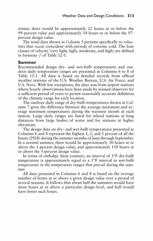
P1: GDZ/FFX P2: GDZ/FFX QC: GDZ/FFX T1: GDZ
GB076-12 GB076-Miller-Sample July 15, 2004 17:47 Char Count= 0
Weather Data and Design Conditions 313
winter, there would be approximately 22 hours at or below the99-percent value and approximately 54 hours at or below the 97-percent design value.
The wind data shown in Column 5 pertains specifically to veloc-ities that occur coincident with periods of extreme cold. The fourclasses of velocity (very light, light, moderate, and high) are definedin footnote f of Table 12-1.
SummerRecommended design dry- and wet-bulb temperatures and out-door daily temperature ranges are presented in Columns 6 to 8 ofTable 12-1. All data is based on detailed records from officialweather stations of the U.S. Weather Bureau, U.S. Air Force, andU.S. Navy. With few exceptions, the data was from airport stationswhere hourly observations have been made by trained observers fora sufficient period of years to permit reasonably accurate definitionof the climatic range for each location.
The outdoor daily range of dry-bulb temperatures shown in Col-umn 7 gives the difference between the average maximum and av-erage minimum temperatures during the warmest month at eachstation. Large daily ranges are listed for inland stations at longdistances from large bodies of water and for stations at higherelevations.
The design data on dry- and wet-bulb temperatures presented inColumns 6 and 8 represent the highest 1, 2, and 5 percent of all thehours (2928) during the summer months of June through September.In a normal summer, there would be approximately 30 hours at orabove the 1-percent design value, and approximately 150 hours ator above the 5-percent design value.
In terms of enthalpy (heat content), an interval of 3◦F dry-bulbtemperature is approximately equal to a 1◦F interval in wet-bulbtemperature in the temperature ranges that prevail during the sum-mer.
All data presented in Columns 6 and 8 is based on the averagenumber of hours at or above a given design value over a period ofseveral seasons. It follows that about half the summers would havemore hours at or above a particular design level, and half wouldhave fewer such hours.
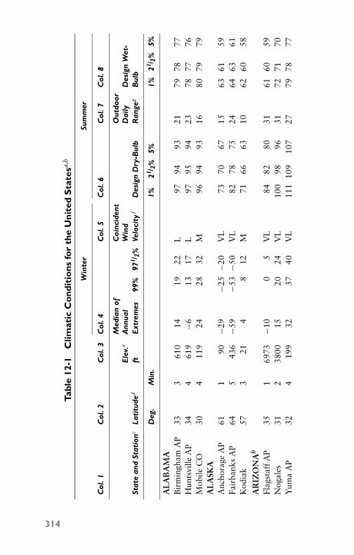
P1: GDZ/FFX P2: GDZ/FFX QC: GDZ/FFX T1: GDZ
GB076-12 GB076-Miller-Sample July 15, 2004 17:47 Char Count= 0
Tabl
e12
-1C
limat
icC
ond
itio
nsfo
rth
eU
nite
dS
tate
sa,b
Win
ter
Sum
mer
Col
.1C
ol.2
Col
.3C
ol.4
Col
.5C
ol.6
Col
.7C
ol.8
Med
ian
ofC
oinc
iden
tO
utdo
orE
lev.
eA
nnua
lW
ind
Dai
lyD
esig
nW
et-
Stat
ean
dSt
atio
ncLa
titu
ded
ftE
xtre
mes
99%
971 /
2%Ve
loci
tyf
Des
ign
Dry
-Bul
bR
ange
gB
ulb
Deg
.M
in.
1%21
/ 2%
5%1%
21/ 2
%5%
AL
AB
AM
AB
irm
ingh
amA
P33
361
014
1922
L97
9493
2179
7877
Hun
tsvi
lleA
P34
461
9−6
1317
L97
9594
2378
7776
Mob
ileC
O30
411
924
2832
M96
9493
1680
7979
AL
ASK
AA
ncho
rage
AP
611
90−2
9−2
5−2
0V
L73
7067
1563
6159
Fair
bank
sA
P64
543
6−5
9−5
3−5
0V
L82
7875
2464
6361
Kod
iak
573
214
812
M71
6663
1062
6058
AR
IZO
NA
h
Flag
staf
fA
P35
169
73−1
00
5V
L84
8280
3161
6059
Nog
ales
312
3800
1520
24V
L10
098
9631
7271
70Y
uma
AP
324
199
3237
40V
L11
110
910
727
7978
77
314

P1: GDZ/FFX P2: GDZ/FFX QC: GDZ/FFX T1: GDZ
GB076-12 GB076-Miller-Sample July 15, 2004 17:47 Char Count= 0
Tabl
e12
-1(c
onti
nued
)
AR
KA
NSA
SFa
yett
evill
eA
P36
012
533
913
M97
9593
2377
7675
Hot
Spri
ngs
Nat
.Pk.
343
710
1218
22M
9997
9622
7978
77Te
xark
ana
AP
333
361
1622
26M
9997
9621
8079
78C
AL
IFO
RN
IAh
San
Fern
ando
341
977
2934
37V
L10
097
9438
7372
71Sa
nFr
anci
sco
CO
375
5238
4244
VL
8077
7314
6462
61Y
reka
414
2625
713
17V
L96
9491
3868
6665
CO
LO
RA
DO
Ala
mos
aA
P37
375
36−2
6−1
7−1
3V
L84
8279
3562
6160
Dur
ango
371
6550
−10
04
M88
8683
3064
6362
Gra
ndJu
ncti
onA
P39
148
49−2
811
M96
9492
2964
6362
CO
NN
EC
TIC
UT
Har
tfor
d,B
rain
ard
Fiel
d41
515
−41
5M
9088
8522
7776
74N
ewL
ondo
n41
260
04
8M
8986
8316
7775
74W
inds
orL
ocks
,B
radl
eyFi
eld
420
169
−7−2
2M
9088
8522
7675
73D
EL
AW
AR
ED
over
AFB
390
388
1315
M93
9088
1879
7877
Wilm
ingt
onA
P39
478
612
15M
9390
8720
7977
76
(con
tinu
ed)
315

P1: GDZ/FFX P2: GDZ/FFX QC: GDZ/FFX T1: GDZ
GB076-12 GB076-Miller-Sample July 15, 2004 17:47 Char Count= 0
Tabl
e12
-1(c
onti
nued
)
Win
ter
Sum
mer
Col
.1C
ol.2
Col
.3C
ol.4
Col
.5C
ol.6
Col
.7C
ol.8
Med
ian
ofC
oinc
iden
tO
utdo
orE
lev.
eA
nnua
lW
ind
Dai
lyD
esig
nW
et-
Stat
ean
dSt
atio
ncLa
titu
ded
ftE
xtre
mes
99%
971 /
2%Ve
loci
tyf
Des
ign
Dry
-Bul
bR
ange
gB
ulb
Deg
.M
in.
1%21
/ 2%
5%1%
21/ 2
%5%
DIS
TR
ICT
OF
CO
LU
MB
IAA
ndre
ws
AFB
385
279
913
16L
9491
8818
7977
76W
ashi
ngto
nN
atio
nalA
P38
514
1216
19V
L94
9290
1878
7776
FLO
RID
AK
eyW
est
AP
243
650
5558
VL
9089
889
8079
79Sa
raso
ta27
230
3135
39M
9391
9017
8080
79Ta
llaha
ssee
AP
302
5821
2529
H96
9493
1980
7979
GE
OR
GIA
Am
eric
us32
047
618
2225
L98
9693
2080
7978
Dal
ton
345
702
1015
19L
9795
9222
7877
76V
oldo
sta-
Moo
dyA
FB31
023
924
2831
L96
9492
2080
7978
HA
WA
IIH
iloA
P19
431
5659
61L
8583
8215
7473
72H
onol
ulu
AP
212
758
6062
L87
8584
1275
7473
Wah
iaw
a21
321
557
5961
L86
8483
1475
7473
316

P1: GDZ/FFX P2: GDZ/FFX QC: GDZ/FFX T1: GDZ
GB076-12 GB076-Miller-Sample July 15, 2004 17:47 Char Count= 0
Tabl
e12
-1(c
onti
nued
)
IDA
HO
Bur
ley
423
4180
−54
8V
L95
9389
3568
6664
ldah
oFa
llsA
P43
347
30r
−17
−12
−6V
L91
8885
3865
6462
Lew
isto
nA
P46
214
131
612
VL
9896
9332
6766
65IL
LIN
OIS
Car
bond
ale
375
380
17
11M
9896
9421
8079
78Fr
eepo
rt42
278
0−1
6−1
0−6
M92
9087
2478
7775
Peor
iaA
P40
465
2−8
−22
M94
9289
2278
7776
IND
IAN
AJe
ffer
sonv
ille
382
455
39
13M
9694
9123
7978
77So
uth
Ben
dA
P41
477
3−6
−23
M92
8987
2277
7674
Val
para
iso
412
801
−12
−6−2
M92
9087
2278
7675
IOW
AM
ason
Cit
yA
P43
111
94−2
0−1
3−9
M91
8885
2477
7574
KA
NSA
SG
arde
nC
ity
AP
380
2882
−10
−13
M10
098
9628
7473
72H
utch
inso
nA
P38
015
24−5
26
H10
199
9628
7776
75W
ichi
taA
P37
413
21−1
59
H10
299
9623
7776
75K
EN
TU
CK
YA
shla
nd38
355
11
610
L94
9289
2277
7675
Cov
ingt
onA
P39
086
9−3
38
L93
9088
2277
7675
Hop
kins
ville
,C
ampb
ellA
FB36
454
04
1014
L97
9592
2179
7877
(con
tinu
ed)
317

P1: GDZ/FFX P2: GDZ/FFX QC: GDZ/FFX T1: GDZ
GB076-12 GB076-Miller-Sample July 15, 2004 17:47 Char Count= 0
Tabl
e12
-1(c
onti
nued
)
Win
ter
Sum
mer
Col
.1C
ol.2
Col
.3C
ol.4
Col
.5C
ol.6
Col
.7C
ol.8
Med
ian
ofC
oinc
iden
tO
utdo
orE
lev.
eA
nnua
lW
ind
Dai
lyD
esig
nW
et-
Stat
ean
dSt
atio
ncLa
titu
ded
ftE
xtre
mes
99%
971 /
2%Ve
loci
tyf
Des
ign
Dry
-Bul
bR
ange
gB
ulb
Deg
.M
in.
1%21
/ 2%
5%1%
21/ 2
%5%
LO
UIS
IAN
AA
lexa
ndri
aA
P31
292
2025
29L
9795
9420
8080
79N
atch
itoc
hes
315
120
1722
26L
9997
9620
8180
79N
ewO
rlea
nsA
P30
03
2932
35M
9391
9016
8180
79M
AIN
EA
ugus
taA
P44
235
0−1
3−7
−3M
8886
8322
7473
71C
arib
ouA
P46
562
4−2
4−1
8−1
4L
8581
7821
7270
68W
ater
ville
443
89−1
5−9
−5M
8886
8222
7473
71M
AR
YL
AN
DB
alti
mor
eA
P39
114
68
1215
M94
9189
2179
7877
Bal
tim
ore
CO
392
1412
1620
M94
9289
1779
7877
Cum
berl
and
394
945
05
9L
9492
8922
7675
74M
ASS
AC
HU
SET
TS
Fram
ingh
am42
217
0−7
−13
M91
8986
1776
7473
Gre
enfie
ld42
320
5−1
2−6
−2M
8987
8423
7574
73N
ewB
edfo
rd41
470
39
13H
8684
8119
7573
72
318
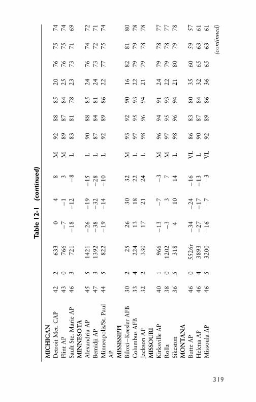
P1: GDZ/FFX P2: GDZ/FFX QC: GDZ/FFX T1: GDZ
GB076-12 GB076-Miller-Sample July 15, 2004 17:47 Char Count= 0
Tabl
e12
-1(c
onti
nued
)
MIC
HIG
AN
Det
roit
Met
.CA
P42
263
30
48
M92
8885
2076
7574
Flin
tA
P43
076
6−7
−13
M89
8784
2576
7574
Saul
tSt
e.M
arie
AP
463
721
−18
−12
−8L
8381
7823
7371
69M
INN
ESO
TA
Ale
xand
ria
AP
455
1421
−26
−19
−15
L90
8885
2476
7472
Bem
idji
AP
473
1392
−38
−32
−28
L87
8481
2473
7271
Min
neap
olis
/St.
Paul
445
822
−19
−14
−10
L92
8986
2277
7574
AP
MIS
SISS
IPPI
Bilo
xi−K
eesl
erA
FB30
225
2630
32M
9392
9016
8281
80C
olum
bus
AFB
334
224
1318
22L
9795
9322
7979
78Ja
ckso
nA
P32
233
017
2124
L98
9694
2179
7878
MIS
SOU
RI
Kir
ksvi
lleA
P40
196
6−1
3−7
−3M
9694
9124
7978
77R
olla
380
1202
−33
7M
9795
9322
7978
77Si
kest
on36
531
84
1014
L98
9694
2180
7978
MO
NT
AN
AB
utte
AP
460
5526
r−3
4−2
4−1
6V
L86
8380
3560
5957
Hel
ena
AP
464
3893
−27
−17
−13
L90
8784
3265
6361
Mis
soul
aA
P46
532
00−1
6−7
−3V
L92
8986
3665
6361
(con
tinu
ed)
319

P1: GDZ/FFX P2: GDZ/FFX QC: GDZ/FFX T1: GDZ
GB076-12 GB076-Miller-Sample July 15, 2004 17:47 Char Count= 0
Tabl
e12
-1(c
onti
nued
)
Win
ter
Sum
mer
Col
.1C
ol.2
Col
.3C
ol.4
Col
.5C
ol.6
Col
.7C
ol.8
Med
ian
ofC
oinc
iden
tO
utdo
orE
lev.
eA
nnua
lW
ind
Dai
lyD
esig
nW
et-
Stat
ean
dSt
atio
ncLa
titu
ded
ftE
xtre
mes
99%
971 /
2%Ve
loci
tyf
Des
ign
Dry
-Bul
bR
ange
gB
ulb
Deg
.M
in.
1%21
/ 2%
5%1%
21/ 2
%5%
NE
BR
ASK
AC
hadr
onA
P42
533
00−2
1−1
3−9
M97
9592
3072
7069
Has
ting
s40
419
32−1
1−3
1M
9896
9427
7775
74K
earn
ey40
421
46−1
4−6
−2M
9795
9228
7675
74N
EV
AD
Ah
Elk
oA
P40
550
75−2
1−1
3−7
VL
9492
9042
6462
61L
asV
egas
AP
361
2162
1823
26V
L10
810
610
430
7271
70R
eno
AP
393
4404
−22
7V
L95
9290
4564
6261
NE
WH
AM
PSH
IRE
Ber
lin44
311
10−2
5−1
9−1
5L
8785
8222
7371
70K
eene
430
490
−17
−12
−8M
9088
8524
7573
72Po
rtsm
outh
,Pea
se43
112
7−8
−23
M88
8683
2275
7372
AFB
NE
WJE
RSE
YA
tlan
tic
Cit
yC
O39
311
1014
18H
9188
8518
7877
76N
ewar
kA
P40
411
611
15M
9491
8820
7776
75Ph
illip
sbur
g40
418
01
610
L93
9188
2177
7675
320

P1: GDZ/FFX P2: GDZ/FFX QC: GDZ/FFX T1: GDZ
GB076-12 GB076-Miller-Sample July 15, 2004 17:47 Char Count= 0
Tabl
e12
-1(c
onti
nued
)
NE
WM
EX
ICO
Clo
vis
AP
343
4279
214
17L
9997
9528
7069
68G
rant
s35
165
20−1
5−7
−3V
L91
8986
3264
6362
Las
Cru
ces
322
3900
1319
23L
102
100
9730
7069
68N
EW
YO
RK
Gen
eva
425
590
−8−2
2M
9189
8622
7573
72M
asse
naA
P45
020
2r−2
2−1
6−1
2M
8684
8120
7574
72N
YC
-Ken
nedy
AP
404
1612
1721
H91
8784
1677
7675
NO
RT
HC
AR
OL
INA
Hen
ders
on36
251
08
1216
L94
9289
2079
7877
Roc
kyM
ount
360
8112
1620
L95
9390
1980
7978
Wilm
ingt
onA
P34
230
1923
27L
9391
8918
8281
80N
OR
TH
DA
KO
TA
Bis
mar
ckA
P46
516
47−3
1−2
4−1
9V
L95
9188
2774
7270
Dev
il’s
Lak
e48
114
71−3
0−2
3−1
9M
9389
8625
7371
69W
illis
ton
481
1877
−28
−21
−17
M94
9087
2571
6967
OH
IOC
inci
nnat
iCO
391
761
28
12L
9492
9021
7877
76N
orw
alk
411
720
−7−1
3M
9290
8722
7675
74To
ledo
AP
414
646r
−51
5M
9290
8725
7775
74O
KL
AH
OM
AA
rdm
ore
342
880
915
19H
103
101
9923
7978
77O
klah
oma
Cit
yA
P35
212
804
1115
H10
097
9523
7877
76W
oodw
ard
363
1900
−34
8H
103
101
9826
7674
73
(con
tinu
ed)
321
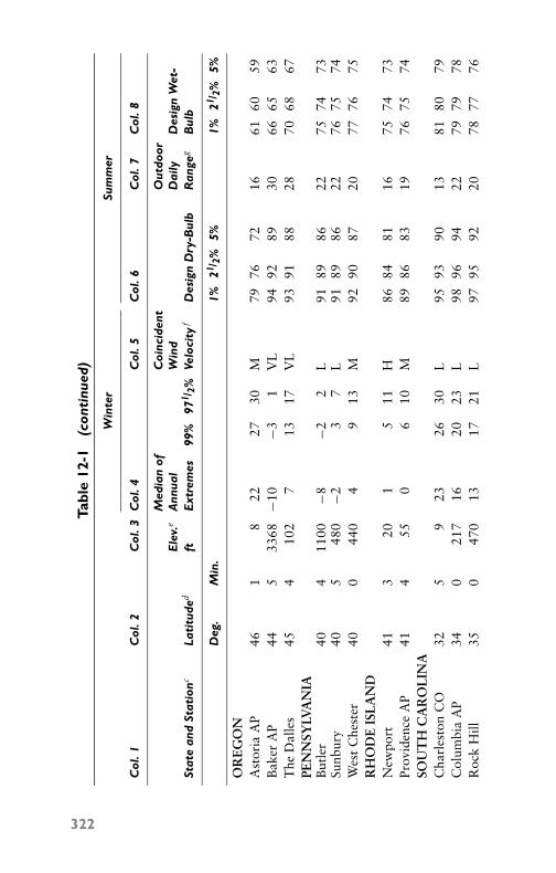
P1: GDZ/FFX P2: GDZ/FFX QC: GDZ/FFX T1: GDZ
GB076-12 GB076-Miller-Sample July 15, 2004 17:47 Char Count= 0
Tabl
e12
-1(c
onti
nued
)
Win
ter
Sum
mer
Col
.1C
ol.2
Col
.3C
ol.4
Col
.5C
ol.6
Col
.7C
ol.8
Med
ian
ofC
oinc
iden
tO
utdo
orE
lev.
eA
nnua
lW
ind
Dai
lyD
esig
nW
et-
Stat
ean
dSt
atio
ncLa
titu
ded
ftE
xtre
mes
99%
971 /
2%Ve
loci
tyf
Des
ign
Dry
-Bul
bR
ange
gB
ulb
Deg
.M
in.
1%21
/ 2%
5%1%
21/ 2
%5%
OR
EG
ON
Ast
oria
AP
461
822
2730
M79
7672
1661
6059
Bak
erA
P44
533
68−1
0−3
1V
L94
9289
3066
6563
The
Dal
les
454
102
713
17V
L93
9188
2870
6867
PEN
NSY
LVA
NIA
But
ler
404
1100
−8−2
2L
9189
8622
7574
73Su
nbur
y40
548
0−2
37
L91
8986
2276
7574
Wes
tC
hest
er40
044
04
913
M92
9087
2077
7675
RH
OD
EIS
LA
ND
New
port
413
201
511
H86
8481
1675
7473
Prov
iden
ceA
P41
455
06
10M
8986
8319
7675
74SO
UT
HC
AR
OL
INA
Cha
rles
ton
CO
325
923
2630
L95
9390
1381
8079
Col
umbi
aA
P34
021
716
2023
L98
9694
2279
7978
Roc
kH
ill35
047
013
1721
L97
9592
2078
7776
322

P1: GDZ/FFX P2: GDZ/FFX QC: GDZ/FFX T1: GDZ
GB076-12 GB076-Miller-Sample July 15, 2004 17:47 Char Count= 0
Tabl
e12
-1(c
onti
nued
)
SOU
TH
DA
KO
TA
Abe
rdee
nA
P45
312
96−2
9−2
2−1
8L
9592
8927
7775
74H
uron
AP
443
1282
−24
−16
−12
L97
9390
2877
7574
Pier
reA
P44
217
18r
−21
−13
−9M
9896
9329
7674
73T
EN
NE
SSE
EB
rist
ol-T
riC
ity
AP
363
1519
−111
16L
9290
8822
7675
74C
hatt
anoo
gaA
P35
067
011
1519
L97
9492
2278
7877
Tulla
hom
a35
210
757
1317
L96
9492
2279
7877
TE
XA
SB
row
nsvi
lleA
P25
516
3236
40M
9492
9118
8080
79K
illee
n-G
ray
AFB
310
1021
1722
26M
100
9997
2278
7776
Pam
pa35
332
300
711
M10
098
9526
7372
71U
TA
HPr
ovo
401
4470
−62
6L
9693
9132
6766
65St
.Geo
rge
CO
371
2899
1322
26V
L10
410
299
3371
7069
Ver
nalA
P40
352
80−2
0−1
0−6
VL
9088
8432
6463
62V
ER
MO
NT
Bar
re44
111
20−2
3−1
7−1
3L
8684
8123
7372
70B
urlin
gton
AP
443
331
−18
−12
−7M
8885
8323
7473
71R
utla
nd43
362
0−1
8−1
2−8
L87
8582
2374
7371
(con
tinu
ed)
323

P1: GDZ/FFX P2: GDZ/FFX QC: GDZ/FFX T1: GDZ
GB076-12 GB076-Miller-Sample July 15, 2004 17:47 Char Count= 0
Tabl
e12
-1(c
onti
nued
)
Win
ter
Sum
mer
Col
.1C
ol.2
Col
.3C
ol.4
Col
.5C
ol.6
Col
.7C
ol.8
Med
ian
ofC
oinc
iden
tO
utdo
orE
lev.
eA
nnua
lW
ind
Dai
lyD
esig
nW
et-
Stat
ean
dSt
atio
ncLa
titu
ded
ftE
xtre
mes
99%
971 /
2%Ve
loci
tyf
Des
ign
Dry
-Bul
bR
ange
gB
ulb
Deg
.M
in.
1%21
/ 2%
5%1%
21/ 2
%5%
VIR
GIN
IAC
harl
otte
svill
e38
187
07
1115
L93
9088
2379
7776
Har
riso
nbur
g38
313
400
59
L92
9087
2378
7776
Nor
folk
AP
365
2618
2023
M94
9189
1879
7878
WA
SHIN
GT
ON
Bel
lingh
amA
P48
515
08
1418
L76
7471
1967
6563
Mos
esL
ake,
Lar
son
AFB
471
1183
−14
−7−1
VL
9693
9032
6866
65Se
attl
eC
O47
414
2228
32L
8179
7619
6765
64W
EST
VIR
GIN
IAE
lkin
sA
P38
519
70−4
15
L87
8482
2274
7372
Hun
ting
ton
CO
382
565r
410
14L
9593
9122
7776
75W
heel
ing
401
659
05
9L
9189
8621
7675
74
324

P1: GDZ/FFX P2: GDZ/FFX QC: GDZ/FFX T1: GDZ
GB076-12 GB076-Miller-Sample July 15, 2004 17:47 Char Count= 0
Tabl
e12
-1(c
onti
nued
)
WIS
CO
NSI
NA
shla
nd46
365
0−2
7−2
1−1
7L
8583
8023
7371
69B
eloi
t42
378
0−1
3−7
−3M
9290
8724
7776
75Sh
eboy
gan
434
648
−10
−40
M89
8784
2076
7472
WY
OM
ING
Cas
per
AP
425
5319
−20
−11
−5L
9290
8731
6362
60C
heye
nne
AP
411
6126
−15
−6−2
M89
8683
3063
6261
Lan
der
AP
425
5563
−26
−16
−12
VL
9290
8732
6362
60a
Dat
afo
rU
.S.s
tati
ons
extr
acte
dfr
om“E
valu
ated
Wea
ther
Dat
afo
rC
oolin
gE
quip
men
tD
esig
n,A
dden
dum
No.
1,W
inte
ran
dSu
mm
erD
ata,
”w
ith
the
perm
issi
onof
the
publ
ishe
r,Fl
uor
Prod
ucts
Com
pany
,Inc
.Box
1267
,San
taR
osa,
CA
.b
Dat
aco
mpi
led
from
offic
ialw
eath
erst
atio
ns,w
here
hour
lyw
eath
erob
serv
atio
nsar
em
ade
bytr
aine
dob
serv
ers
and
from
othe
rso
urce
s.Ta
ble
12-1
prep
ared
byA
SHR
AE
Tech
nica
lCom
mit
tee
2.2,
Wea
ther
Dat
aan
dD
esig
nC
ondi
tion
s.Pe
rcen
tage
ofw
inte
rde
sign
data
show
sth
epe
rcen
tof
thre
e-m
onth
peri
od,D
ecem
ber
thro
ugh
Febr
uary
.Can
adia
nda
tais
base
don
Janu
ary
only
.Per
cent
age
ofsu
mm
erde
sign
data
show
sth
epe
rcen
tof
afo
ur-m
onth
peri
od,J
une
thro
ugh
Sept
embe
r.C
anad
ian
data
isba
sed
onJu
lyon
ly.
cW
hen
airp
ort
tem
pera
ture
obse
rvat
ions
wer
eus
edto
deve
lop
desi
gnda
ta,“
AP”
follo
ws
stat
ion
nam
e,an
d“A
FB”
follo
ws
Air
Forc
eB
ases
.D
ata
for
stat
ions
follo
wed
by“C
D”
cam
efr
omof
fice
loca
tion
sw
ithi
nan
urba
nar
eaan
dge
nera
llyre
flect
anin
fluen
ceof
the
surr
ound
ing
area
.St
atio
nsw
itho
utde
sign
atio
nca
nbe
cons
ider
edse
mi-
rura
land
may
bedi
rect
lyco
mpa
red
wit
hm
ost
airp
ort
data
.d
Lat
itud
eis
give
nto
the
near
est
10m
inut
es,f
orus
ein
calc
ulat
ing
sola
rlo
ads.
For
exam
ple,
the
lati
tude
for
Ann
isto
n,A
laba
ma
isgi
ven
as33
.4or
33◦
40′′ .
eE
leva
tion
sar
egr
ound
elev
atio
nsfo
rea
chst
atio
nas
of19
64.T
empe
ratu
rere
adin
gsar
ege
nera
llym
ade
atan
elev
atio
nof
5fe
etab
ove
grou
nd,
exce
ptfo
rlo
cati
ons
mar
ked
r,in
dica
ting
roof
expo
sure
ofth
erm
omet
er.
fC
oinc
iden
tw
ind
velo
citi
esde
rive
dfr
omap
prox
imat
ely
cold
est
600
hour
sou
tof
20,0
00ho
urs
ofD
ecem
ber
thro
ugh
Febr
uary
data
per
stat
ion.
VL
=V
ery
Lig
ht,7
0pe
rcen
tor
mor
eof
cold
extr
eme
hour
s≤7
mph
;M=
Mod
erat
e,50
to74
perc
ent
cold
extr
eme
hour
s>
7m
ph;L
=L
ight
,50
to69
perc
ent
cold
extr
eme
hour
s≤7
mph
;H=
Hig
h,75
perc
ent
orm
ore
cold
extr
eme
hour
s>
7m
ph,a
nd50
perc
ent
are
>12
mph
.g
The
diff
eren
cebe
twee
nth
eav
erag
em
axim
uman
dav
erag
em
inim
umte
mpe
ratu
res
duri
ngth
ew
arm
est
mon
th.
hM
ore
deta
iled
data
onA
rizo
na,C
alif
orni
a,an
dN
evad
am
aybe
foun
din
“Rec
omm
ende
dD
esig
nTe
mpe
ratu
res,
Nor
ther
nC
alif
orni
a,”
publ
ishe
dby
the
Gol
den
Gat
eC
hapt
er,a
nd“R
ecom
men
ded
Des
ign
Tem
pera
ture
s,So
uthe
rnC
alif
orni
a,A
rizo
na,N
evad
a,”
publ
ishe
dby
the
Sout
hern
Cal
ifor
nia
Cha
pter
.
325

P1: GDZ/FFX P2: GDZ/FFX QC: GDZ/FFX T1: GDZ
GB076-12 GB076-Miller-Sample July 15, 2004 17:47 Char Count= 0
326 Chapter 12
Interpolation among StationsData from many weather stations at specific locations and at pub-lished elevations furnish a network from which, by interpolation,good estimates can be made of the expected conditions at a preciselocation:� Adjustment for Elevation—For a lower elevation, the design
values from Table 12-1 should be increased, while for a higherelevation, the values should be decreased. The increments usedin these adjustments are as follows:� Dry-bulb temperature: 1◦F per 200 feet� Wet-bulb temperature: 1◦F per 500 feet� Adjustment for Air-Mass Modification—Short-distance varia-
tions are most extreme near large bodies of water where airmoves from the water over the land in the summer. Alongthe West Coast, both dry- and wet-bulb temperatures increasewith distance from the ocean. In the region north of the Gulfof Mexico, dry-bulb temperatures increase for the first 200 or300 miles, with a very slight decrease in wet-bulb temperaturebecause of mixing and drier inland air. Beyond this 200- to300-mile belt, both dry- and wet-bulb values tend to decreaseat a somewhat regular rate.� Adjustment for Vegetation—The difference between large ar-
eas of dry surfaces and large areas of dense foliage upwindfrom the site can account for variations of up to 2◦F wet-bulband 5◦F dry-bulb temperature. The warmer temperatures areassociated with the dry surfaces. If the nearest official weatherstation is well-surrounded by buildings and streets (large drysurfaces) and the precise location where required design datais similarly surrounded, no adjustment is needed. However, ifthe local exposure at the location site is quite different fromthe nearest weather station listed in Table 12-1, an adjustmentof 1◦F wet-bulb and 2◦F dry-bulb temperature may be easilyjustified.
Weather-Oriented Design FactorsThe rational approach to air-conditioning system design involvescomputation of a peak design load at a condition established usingone of the frequency of occurrence levels (see Table 12-1, Columns6 and 8) of dry- and wet-bulb weather data published herein.
Although the values enumerated are statistically quite accurate,certain precautions are recommended concerning their use. These

P1: GDZ/FFX P2: GDZ/FFX QC: GDZ/FFX T1: GDZ
GB076-12 GB076-Miller-Sample July 15, 2004 17:47 Char Count= 0
Weather Data and Design Conditions 327
figures are frequency-distribution statistics for the ends of the distri-bution. During the four warmest summer months, these values occurat an hour of the day usually between 2:00 p.m. and 4:00 p.m., suntime. The winter statistics occur during the three coldest months atan hour of the day usually between 6:00 a.m. and 8 a.m., sun time.The daily dry-bulb variation will be of the order of the daily rangestated on typical design days. However, statistically the daily range(see Table 12-1, Column 7) is the long-term average daily range foronly the warmest month. The daily range is generally greater duringclear weather and much less during cloudy weather or precipitation.
A very crude approximation of the distribution of the hourly dry-bulb temperatures during a design day can be made by locating thedaily maximum at 3:00 p.m. and the minimum (maximum less dailyrange) at 7:00 a.m. This day, basically, is made up of 12 or moredaylight hours of solar heating and 12 or less hours of nighttimeradiant cooling.
Throughout the continental or inland mass of the United States,the maximum dry-bulb and maximum wet-bulb temperatures arenot coincident. In fact, the 1-percent level values rarely occur at thesame time in such areas. In maritime areas, they tend to be coin-cident. Typically, the maximum dry-bulb temperature is coincidentwith a wet-bulb substantially below the maximum wet-bulb tem-perature and vice versa. The assumption of dry- and wet-bulb coin-cidence can result in weather-oriented loads up to one-half greaterthan might otherwise be expected. A rational solution would be todetermine whether the structure was the most sensitive to dry-bulb(that is, extensive exterior) or wet-bulb (that is, outside-air ventila-tion). Then the appropriate maximum temperature could be usedfor design with its corresponding coincident value. This could beascertained for any station by an analysis involving usually onlya day or two of hand calculations. An outline of this approachfollows.
From at least 5 years of local weather records, select days con-taining the maximum wet- and dry-bulb entries in any time frame(hourly, every 3 hours, and so on) for that station. On the published3-hour increments, tabulate the dry-bulb peak with the correspond-ing wet-bulb and the wet-bulb with its corresponding dry-bulb. Thistabulation will illustrate not only the local coincident data, but alsothe 3-hour temperature array for a typical design day that is accuratewithin a degree or two.
This procedure is certainly within the capability of any engineer-ing office that is involved in several local projects. Where projectsof greater significance are involved, there are several alternatives.

P1: GDZ/FFX P2: GDZ/FFX QC: GDZ/FFX T1: GDZ
GB076-12 GB076-Miller-Sample July 15, 2004 17:47 Char Count= 0
328 Chapter 12
A longer period of record (such as 10 years) can be studied. Hourlydata instead of the usual 3-hour interval can be used. Machine tab-ulations can be made on any desired criteria. Consulting meteorol-ogists are available to analyze both the raw data and the statisticalcompilations.
As more complicated and sophisticated applications are utilizedto meet critical demands, these design maximums based on peakvalues will not suffice. Engineers will have to consider off-peakvalues. Some types of days that must be accommodated are morefrequent in occurrence than maximum or minimum design days.Examples of these include the following: Cloudy—small tempera-ture change; Windy; Warm a.m., Cool p.m.; and, of course, Fair andWarm, and Fair and Cool. Quite often due to temperature-controlimplication, these days must be studied before a final design can beimplemented.
Since the advent of machine computations, many system design-ers are making calculations of dry-bulb temperature with its cor-responding wet-bulb maximum, and vice versa, for several hoursdaily on both a room-by-room basis and a zone or building ba-sis. This can result in more accurate design data and compatiblesystems in operation. Furthermore, the trend of the industry to at-tempt energy-consumption estimates to establish system design ismaking some progress.
SummaryThe indoor conditions to be maintained within a building are thedry-bulb temperature and relative humidity of the air at a breathingline 3 to 5 feet above the floor in an area that would indicate averageconditions at that level.
For summer cooling, a relative humidity of 50 percent may bechosen for the average job in the United States. In arid climates, adesign relative humidity of 40 percent is more realistic. The relativehumidity should not exceed 60 percent at any point in the occu-pied space and normally should not fall below 20 percent to pre-vent human nostrils from becoming dry and furniture from dryingout.
Adjustments must be made for a number of factors when you aredesigning an air-conditioning system for human comfort.
The trend of the air-conditioning industry is to attempt energy-consumption estimates to establish system design. This trend seemsto be making some progress.
P1: GDZ/FFX P2: GDZ/FFX QC: GDZ/FFX T1: GDZ
GB076-12 GB076-Miller-Sample July 15, 2004 17:47 Char Count= 0
Weather Data and Design Conditions 329
Review Questions1. What is the distance above the floor that is used as a standard
for making comfort measurements in air conditioning?2. What is the difference between dry- and wet-bulb temperature
readings?3. How long were temperature readings taken to establish a stan-
dard for the region?4. Where were the temperature readings taken for each locality?5. During the summer, what is the heat content shown by an
interval of 3◦F dry-bulb in terms of wet-bulb temperatures?6. How do you make adjustments for air-mass modification?7. What is the adjustment made for vegetation?8. How do the dry- and wet-bulb maximum temperatures coin-
cide throughout the continental or inland mass of the UnitedStates?
9. What is the trend of the air-conditioning industry in regardto using energy- consumption figures instead of temperaturesto determine design factors and load characteristics for air-conditioning equipment?
10. What does ASHRAE stand for?

P1: GDZ/FFX P2: GDZ/FFX QC: GDZ/FFX T1: GDZ
GB076-12 GB076-Miller-Sample July 15, 2004 17:47 Char Count= 0
330

P1: GDZ/FFX P2: GDZ/FFX QC: GDZ/FFX T1: GDZ
GB076-13 GB076-Miller-Sample July 15, 2004 9:6 Char Count= 0
Chapter 13Year-Round CentralAir ConditioningYear-round air conditioning is required to warm the air to a com-fortable temperature during the winter and, in addition, wash, filter,and humidify it. During the summer, an air-conditioning system isrequired to cool the air, plus perform the necessary humidification ordehumidification as required. A year-round air-conditioning systemshould accomplish the following:
� Eliminate the dust, soot, and germs from the air entering theintake ducts.� Warm the air in winter.� Cool the air in summer.� Increase the humidity in winter operation.� Decrease the relative humidity or moisture content of the air
in summer operation.� Circulate the conditioned air evenly and pleasantly throughout
the building at all times.
Modern year-round central air-conditioning systems may be clas-sified with respect to nature of service as follows: gas-compressionsystem, absorption system, and steam-jet vacuum system.
The gas-compression (or mechanical) air-conditioning methodconsists simply of a refrigeration system employing a mechanicalcompression device (compressor) to remove the low-pressure refrig-erant enclosed in the low-pressure side, and deliver it to the high-pressure side of the system.
An absorption air-conditioning system is one in which the re-frigerant gas evolved in the evaporator is taken up by an absorberand released in a generator upon application of heat. A steam-jetair-conditioning system is a vacuum-refrigeration system in whichhigh-pressure steam supplied through a nozzle and acting to ejectwater from the evaporator maintains the requisite low pressure inthe evaporator, producing the required pressure on the high side byvirtue of compression in a following diffusion passage.
Central System FeaturesA central air-conditioning system is generally a system designed forassembly in the field rather than in the factory as a unit. The principal
331

P1: GDZ/FFX P2: GDZ/FFX QC: GDZ/FFX T1: GDZ
GB076-13 GB076-Miller-Sample July 15, 2004 9:6 Char Count= 0
332 Chapter 13
advantage in a central air-conditioning system lies in the fact thatone condensing unit servicing several rooms will result in lower costthan a number of self-contained units serving single rooms.
Central air-conditioning systems are usually provided with airducts to the various rooms served, and, in addition, to a properlyplaced exhaust fan to effect complete removal and disposal of anydesired proportion of the air.
Air-Supply SystemA fresh air intake should be located at some strategic point so thatdust, dirt, and fumes from the street or odors from kitchens andsurrounding buildings will not be drawn into the house. The airtaken into the fresh air intake should be as pure as possible. Whilethe system will remove the undesirable dust and dirt by means offilters, highly impure air will only place an additional burden on thesystem and result in an increase in the cost of operation. Figures 13-1and Figure 13-2 show the typical equipment for a central year-roundair-conditioning system.
FANPULLEY
DISCHARGEAIR
PREHEATER
FAN
COOLINGCOILS
ACCESSDOORSFILTER
RETURNAIR
OUTSIDEAIR
DAMPERS TEMPERINGCOIL
WATER SPRAY(HUMIDIFIER) BY-PASS
DAMPERS
BY-PASS
Figure 13-1 Equipment for a central year-round air-conditioningsystem.
Mixing ChamberA mixing chamber is generally incorporated into the system for thepurpose of recirculating a portion of the air within the building in or-der to reduce the load and operating costs. In the summer the cooledair and in the winter the heated air is mixed with the fresh air drawnin from outside, so that the load is reduced considerably. A certainamount of fresh air is drawn in and mixed with the recirculated air,which may be accomplished by using a simple mixing damper. The
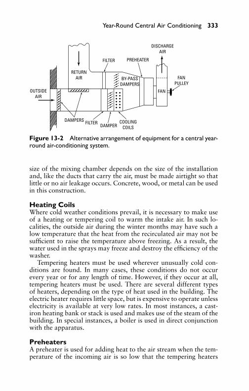
P1: GDZ/FFX P2: GDZ/FFX QC: GDZ/FFX T1: GDZ
GB076-13 GB076-Miller-Sample July 15, 2004 9:6 Char Count= 0
Year-Round Central Air Conditioning 333
FANPULLEY
DISCHARGEAIR
PREHEATER
FAN
RETURNAIR
FILTER
FILTER
OUTSIDEAIR
DAMPERDAMPERS COOLING
COILS
BY-PASSDAMPERS
Figure 13-2 Alternative arrangement of equipment for a central year-round air-conditioning system.
size of the mixing chamber depends on the size of the installationand, like the ducts that carry the air, must be made airtight so thatlittle or no air leakage occurs. Concrete, wood, or metal can be usedin this construction.
Heating CoilsWhere cold weather conditions prevail, it is necessary to make useof a heating or tempering coil to warm the intake air. In such lo-calities, the outside air during the winter months may have such alow temperature that the heat from the recirculated air may not besufficient to raise the temperature above freezing. As a result, thewater used in the sprays may freeze and destroy the efficiency of thewasher.
Tempering heaters must be used wherever unusually cold con-ditions are found. In many cases, these conditions do not occurevery year or for any length of time. However, if they occur at all,tempering heaters must be used. There are several different typesof heaters, depending on the type of heat used in the building. Theelectric heater requires little space, but is expensive to operate unlesselectricity is available at very low rates. In most instances, a cast-iron heating bank or stack is used and makes use of the steam of thebuilding. In special instances, a boiler is used in direct conjunctionwith the apparatus.
PreheatersA preheater is used for adding heat to the air stream when the tem-perature of the incoming air is so low that the tempering heaters

P1: GDZ/FFX P2: GDZ/FFX QC: GDZ/FFX T1: GDZ
GB076-13 GB076-Miller-Sample July 15, 2004 9:6 Char Count= 0
334 Chapter 13
on which the heating load falls are unable to maintain the required68◦F or 70◦F at the fan.
The preheater is necessary only where extreme temperature con-ditions are encountered. In many instances, preheaters are elimi-nated as unnecessary or tempering heaters are constructed with anoverabundance of surface or sections, so that, when required, addi-tional heating surface is available to carry the heating load.
Cooling CoilsCooling coils are used for cooling the air during the summer months.Cooling coils may be chilled by means of refrigerants or a pump-forced liquid (such as brine or water). A watertight drainage tankmust be installed under the cooling coil, and the accumulated watershould be drained by means of a properly air-vented waste trap.
If water of the proper coolness is obtainable in sufficient quantity(as is the case in many northern cities), it may be employed, requiringonly a pumping apparatus to lift it out of the ground. Where it isdifficult to secure water of proper temperature, or where it exists sodeeply underground that pumping costs would be excessive, it thenbecomes necessary to use some other method of cooling the waterused in the washers.
Cold water can be secured by the use of ice or mechanical re-frigeration equipment. Mechanical apparatus, while expensive, isavailable at all times to cope with sudden loads (such as weatherconditions). Ice has no real initial cost and, of course, is depend-able, because it can develop no mechanical trouble. However, if notused up, it will melt away without any returns being derived from it.
Air-Supply FansSupply fans and blowers are made in various types for specific pur-poses, and the selection of the proper type is important if the op-eration is to be economical and efficient. In general, fans used inair-conditioning work may be divided into two types: propeller andcentrifugal and turbine.
Propeller fans are used where there are short ducts or when thereare no ducts. The low speed of the blades near the hub, comparedwith the peripheral speed, makes this form of fan unsuitable whenused to overcome the heavy resistance encountered in long ducts.The air driven by the effective blade areas near the rim finds it easierto pass back through the less effective blade areas at the hub thanto push against the duct resistance.
Propeller fans are adapted to all installations to either supplyor exhaust air without the use of a duct, or at most, a very short
P1: GDZ/FFX P2: GDZ/FFX QC: GDZ/FFX T1: GDZ
GB076-13 GB076-Miller-Sample July 15, 2004 9:6 Char Count= 0
Year-Round Central Air Conditioning 335
duct. Because of noise tendency, this type of fan is more practicalfor commercial and industrial work. Noise and vibration incident tooperation are not objectionable in the commercial field, but wouldbe objectionable in other installations.
The majority of air-conditioning installations (other than theportable or self-contained room coolers) require long air ductsto carry the conditioned air to the various parts of the building.Centrifugal-and-turbine–type fans are employed for the purpose.
FiltersAir filters may be mechanically cleaned, of the replaceable type, orof the electronic type. The air filter is one part of the air-conditioningsystem that can be operated the year round. There are times when theair washer and cooling and humidifying apparatus are not needed,but the filter is one part of the system that may be kept in continuousoperation.
Air WashersThe air washer is a unit that brings the air into intimate contactwith water or a wet surface. In some cases, the air is passed over thewet surface. A more intimate contact is afforded where the wateris divided into a fine spray and the air passed through the spraychamber.
The water is generally circulated by means of a pump, the warmwater being passed over refrigerating coils or blocks of ice to coolit before being passed to the spray chamber. The water lost in evap-oration is automatically replaced by the use of a float arrangement,which admits water from the main as required. In many localities,the water is sufficiently cool to employ just as it is drawn from theground. In other places, the water is not cool enough and must becooled by means of ice or a refrigerating machine.
The principal functions of the air washer are to cool the air passedthrough the spray chamber and control the humidity. In many cases,the cooling coils are located in the bottom of the spray chamber sothat, as the warm spray descends, it is cooled and ready to again besprayed by the pump. As some of the finer water particles tend tobe carried along with the air current, a series of curved plates calledeliminators is generally used, which force the cooled and humidifiedair to change the direction of flow, throwing out or eliminating thewater particles in the process.
Control MethodA control board is frequently a part of a large system so that a recordof operations and conditions can be secured. In air-conditioning

P1: GDZ/FFX P2: GDZ/FFX QC: GDZ/FFX T1: GDZ
GB076-13 GB076-Miller-Sample July 15, 2004 9:6 Char Count= 0
336 Chapter 13
systems, various automatic controls are used. Wet- and dry-bulbtemperatures (which show the temperature and humidity present)are always used. A hygrostat is sometimes used on smaller installa-tions, while most small room coolers are manually controlled sincethey only operate during certain hours of the day.
Zone ControlZone control is generally a division of the air supply delivered intozones with varying requirements. A zone is an area among a numberof areas that are all being conditioned by a single supply system. Eachzone can be satisfied simultaneously with the use of either single- ormultizone control, depending on the number and size of each zone.The conventional single-zone units must be installed one to eachzone, which results in a simpler application in many aspects. Singleunits are recommended whenever each zone is large enough to justifya separate unit and when the system layout will accommodate thisnumber of units (see Figure 13-3).
PROPORTIONALSTEAM VALVES
DISCHARGE AIRZONE 1
ZONE 2
TEMPERINGCOIL
DISCHARGE AIR
DUCTTHERMOSTAT TEMPERING
COIL
FAN COOLED AIR
TEMPERINGCOIL
PROPORTIONALROOM THERMOSTATS
PROPORTIONALSTEAM VALVE
Figure 13-3 Arrangement for two-zone, constant-volume, variable-temperature control.
The use of multizone control is preferred whenever several rel-atively small zones can be grouped together and handled by one

P1: GDZ/FFX P2: GDZ/FFX QC: GDZ/FFX T1: GDZ
GB076-13 GB076-Miller-Sample July 15, 2004 9:6 Char Count= 0
Year-Round Central Air Conditioning 337
control. The requirement of treating simultaneously varying loadswith one unit leads to the following recommendations for obtain-ing the most economical and satisfactory results from multizoneunits:� If both heating and cooling are employed and more than one
multizone unit is used, the grouping should place on each unitthose zones having the least variation with respect to eachother.� The heating and cooling supply should be capable of capacity
reduction to nearly zero.
The purpose of the multizone arrangement is to divide the totalair volume into a number of separate portions and condition eachindependently in accordance with the requirements of the area itserves. This is accomplished through the operation of the zoningdampers, which provide the necessary individualized control. Theair outlet from the unit is partitioned into a number of equal-sizedzones, each equipped with a set of dampers. The dampers are com-posed of two blades set at 90◦ angles to one another on the sameshaft, so that one controls air from the heating pass and the othercontrols air from the cooling pass. By regulating the position ofthe shaft, the air through the two passes can be proportioned tomaintain the desired final temperature in each zone, providing suchtemperatures are feasible with existing coil conditions.
In operation, the shaft from each damper may be extended eitherupward or downward to permit convenient field installation of adamper motor, either electric or pneumatic, as provided. All dampershafts are connected together by one continuous link, which may bekept intact or cut between any or all adjacent zones. Thus, groupsof two or more adjacent dampers may be kept interlocked togetherfor identical movement by one common motor. Each damper mayalso be individually operated by its own motor. This unique (yetsimple) arrangement provides a maximum of flexibility when sup-porting the total airflow from the unit according to the various zonerequirements.
System SelectionIn any year-round air-conditioning application, it is necessary firstto determine the overall accomplishment required of the unit. Thisconsists of surveying the building details and available services, cal-culating the needed capacity of conditions of operation, and devis-ing a layout of the system. Figure 13-4 shows a typical year-roundair-conditioning unit.

P1: GDZ/FFX P2: GDZ/FFX QC: GDZ/FFX T1: GDZ
GB076-13 GB076-Miller-Sample July 15, 2004 9:6 Char Count= 0
338 Chapter 13
RETURNLOOP
CONDUITSUPPLY RISER
PRIMARY AIR
RETURNEDROOM AIR
OUTSIDEAIR
PREHEATCOIL
COOLINGCOIL
REHEATINGCOIL
FILTERS
MAIN CHILLEDWATER PUMP
RECIRCULATINGSPRAY
REFRIGERATIONMACHINE
SECONDARYPUMP
3-WAY VALVE
BOILER
FAN
HOT ORCHILLEDWATER
AIR TERMINAL
WEATHER MASTER UNIT
SECONDARYROOM AIR
SOUND ABSORBER
Figure 13-4 Typical year-round air-conditioning system showing inter-connection of conduits and refrigeration piping. (Courtesy Carrier Corporation.)
A second step is to translate the system-design requirements intospecific equipment selections. The general procedure for selecting aunit is first to determine what casing is to be used, and then makeindividual selections of each of the component items (coils, fans,filters, and so on) that are to go with the casing. Because it servesas the enclosure for the unit, the selection of a casing is essentiallythe determination of the size and basic arrangement of the unit. Thefactors that lead to this selection are the principal requirements ofthe job as to airflow, heat transfer, and configuration to match thesystem layout. Once the casing size is known, the selection of eachcomponent becomes a straightforward procedure and can be madefrom the manufacturer’s catalog.
Absorption-Type Air ConditioningYear-round air conditioners operating on the absorption principlediffer from the conventional compression type mainly in that theyuse heat energy instead of mechanical energy to change the conditionrequired in the refrigeration cycle.
Absorption versus CompressionA comparison between the functioning of an absorption system anda compression system of air conditioning is principally as follows.

P1: GDZ/FFX P2: GDZ/FFX QC: GDZ/FFX T1: GDZ
GB076-13 GB076-Miller-Sample July 15, 2004 9:6 Char Count= 0
Year-Round Central Air Conditioning 339
The absorption system uses heat (usually steam) to circulate therefrigerant, while the compression system employs a compressor tocirculate the refrigerant.
Four components of the absorption system may be comparedwith four components of the compression system, as follows:� The boiler or generator compares with the stroke of the com-
pressor.� The condenser and evaporator serve the same purpose in an
absorption system as in the compression system of refrigera-tion.
Cycle of OperationA typical absorption system is shown diagrammatically in Figure13-5. The system is charged with lithium bromide (the absorbent)and water (the refrigerant). As noted in Figure 13-5, the upper ves-sel contains the absorber and evaporator, whereas the lower vesselcontains the condenser, generator, and heat exchanger. The refrig-eration, or chilling effect, takes place in the evaporator. Refrigerant(water) supplied to the evaporator section is sprayed by the refrig-erant pump over a tube bundle through which the water passes tobe chilled. The refrigerant evaporates on the tube surface. The heatrequired to evaporate the refrigerant is taken from the water in thetubes, thereby chilling the water. The evaporator is maintained at0.25 in Hg, a pressure low enough that the boiling temperature ofthe refrigerant is sufficiently low to produce the desired chilled-watertemperature leaving the unit.
The pressure of the evaporator is maintained at this desired levelby drawing off the refrigerant vapor as it is produced. This vapor isproduced by locating an absorbent adjacent to the evaporator in theabsorber section. The absorbent has a very strong affinity for wa-ter vapor. It will take this vapor into solution as it is produced.The solution used is lithium bromide brine at about 62 percentconcentration. Lithium bromide is sprayed by the absorber pumpinto the absorber to provide as large a liquid surface as possible,since the absorption process is one of contact with the water vapor.As the solution falls from the sprays, it contacts and passes througha tube bundle, which cools the solution and removes the heat lib-erated to the solution when the refrigerant vapor is absorbed andreturns to its liquid state. It is through this heat exchange that theheat removed from the chilled water is rejected from the machineand passed to a cooling tower or other heat sink.
As the absorption process continues, the solution in the absorberbecomes more diluted, and its tendency is to lose its ability to absorb

P1: GDZ/FFX P2: GDZ/FFX QC: GDZ/FFX T1: GDZ
GB076-13 GB076-Miller-Sample July 15, 2004 9:6 Char Count= 0
340 Chapter 13
CHILLED WATER ABSORBER
EVAPORATORSPOILER
VALVE
CONDENSER
GENERATORLP
STEAM
HOTWATER
REFRIGERANTPUMP
ABSORBERPUMP
OR
2
3 1
REFRIGERANTSTEAM OR HOT WATERSOLUTIONCOOLING WATER
HEAT EXCHANGER
Figure 13-5 Schematic-flow diagram of absorption-refrigerationcycle. (Courtesy Worthington Corporation.)

P1: GDZ/FFX P2: GDZ/FFX QC: GDZ/FFX T1: GDZ
GB076-13 GB076-Miller-Sample July 15, 2004 9:6 Char Count= 0
Year-Round Central Air Conditioning 341
at the same rate as vapor is produced. Therefore, the absorber solu-tion is replenished with a strong solution to maintain the requiredconcentration. An equivalent amount of weak solution from theabsorber pan drops down pipe 1 (see Figure 13-5) by gravity andflows through one side of the heat exchanger into the generator,where heat is applied inside a tube bundle from low-pressure steamor hot water. The heat applied raises the weak solution to its boilingpoint and drives off the water vapor. The solution becomes strongand flows out of the generator through the other side of the heatexchanger. It is then drawn into an ejector. This is where it mixeswith intermediate-strength solution in the ejector, and is pumpedback to the absorber to do more work.
The refrigerant vapor that is driven off in the generator flowsinto the condenser, where it is condensed. The condensing mediumis the same water that was used to cool the solution in the absorber,mentioned previously. The condensed refrigerant accumulates in thecondenser pan and is forced by a pressure difference back to theevaporator. The heat exchanger removes heat from the hot, strongsolution, which must be cooled to work in the absorber, and trans-fers it to the weak solution, which must be heated before it can beconcentrated. The cycle is now complete, and the process will con-tinue as long as heat is available and liquid flows are maintained.
The system is controlled by matching the absorber capacity to thechiller load. Absorber capacity is varied by modulating the solutionconcentration, which is controlled by varying the amount of strongsolution that may be withdrawn from the generator. The ejector isa constant-flow device. It will take whatever solution is availablefrom the ejector weir box. When less than full capacity is required,a weak solution from the absorber is bled into the weir box. Thisweak solution will displace the strong solution, preventing the strongsolution from flowing into the ejector. The result is a weakening ofthe absorber-solution strength. This ejector spoilage is accomplishedby modulating valve 2 (see Figure 13-5) in bleed line 3 in accordancewith the leaving chilled-water temperature.
Actual unit construction includes additional refinements, whichincrease efficiency, but the cycle just described is typical of the cyclein any absorption system.
Reverse-Cycle Air Conditioning (Heat Pumps)Year-round air-conditioning units of this type (usually termed heatpumps) operate on the reverse-cycle principle. By means of a spe-cially designed reversing valve, alternate heating and cooling canbe obtained. The operation of a typical unit during the heating
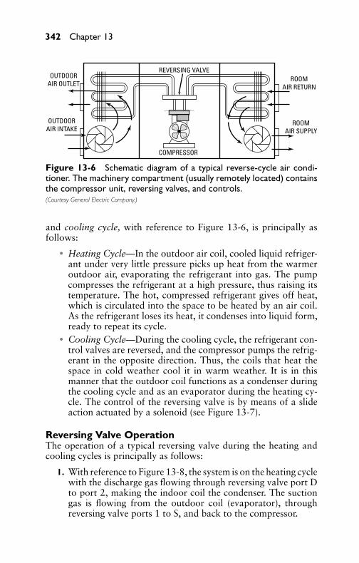
P1: GDZ/FFX P2: GDZ/FFX QC: GDZ/FFX T1: GDZ
GB076-13 GB076-Miller-Sample July 15, 2004 9:6 Char Count= 0
342 Chapter 13
REVERSING VALVEOUTDOOR
AIR OUTLET
OUTDOORAIR INTAKE
COMPRESSOR
ROOMAIR SUPPLY
ROOMAIR RETURN
Figure 13-6 Schematic diagram of a typical reverse-cycle air condi-tioner. The machinery compartment (usually remotely located) containsthe compressor unit, reversing valves, and controls.(Courtesy General Electric Company.)
and cooling cycle, with reference to Figure 13-6, is principally asfollows:� Heating Cycle—In the outdoor air coil, cooled liquid refriger-
ant under very little pressure picks up heat from the warmeroutdoor air, evaporating the refrigerant into gas. The pumpcompresses the refrigerant at a high pressure, thus raising itstemperature. The hot, compressed refrigerant gives off heat,which is circulated into the space to be heated by an air coil.As the refrigerant loses its heat, it condenses into liquid form,ready to repeat its cycle.� Cooling Cycle—During the cooling cycle, the refrigerant con-
trol valves are reversed, and the compressor pumps the refrig-erant in the opposite direction. Thus, the coils that heat thespace in cold weather cool it in warm weather. It is in thismanner that the outdoor coil functions as a condenser duringthe cooling cycle and as an evaporator during the heating cy-cle. The control of the reversing valve is by means of a slideaction actuated by a solenoid (see Figure 13-7).
Reversing Valve OperationThe operation of a typical reversing valve during the heating andcooling cycles is principally as follows:
1. With reference to Figure 13-8, the system is on the heating cyclewith the discharge gas flowing through reversing valve port Dto port 2, making the indoor coil the condenser. The suctiongas is flowing from the outdoor coil (evaporator), throughreversing valve ports 1 to S, and back to the compressor.

P1: GDZ/FFX P2: GDZ/FFX QC: GDZ/FFX T1: GDZ
GB076-13 GB076-Miller-Sample July 15, 2004 9:6 Char Count= 0
RIGH
T PO
RTPL
UNGE
R N
EEDL
EPL
UNGE
R SP
RIN
GSO
LEN
OID
COIL
LOCK
NUT
PLUN
GER
LEFT
POR
TST
AIN
LESS
STE
EL P
INS
LEFT
NEE
DLE
LEFT
SPR
ING
LEFT
CAP
ILLA
RY
COM
MON
(SUC
TION
)CA
PILL
ARY
BLEE
D HO
LE
PIST
ON N
EEDL
E
MAI
N B
ODY IN
SIDE
COIL
REST
RICT
OROU
TSID
ECO
ILCO
MPR
ESSO
RSUCT
ION
TUB
ES
TEFL
ON P
ISTO
NSE
AL
RIGH
T CA
PILL
ARY
DISC
HARG
ETU
BE
SLID
E
SLID
EBR
ACKE
T
PILO
T VA
LVE
BODY
Fig
ure
13-7
Sect
iona
lvie
wof
are
vers
ing
valv
esh
owin
gth
eva
lve
conn
ectio
nin
toa
heat
-pum
psy
stem
for
cool
ing
and
heat
ing.
(Cou
rtes
yRa
nco
Inte
rnat
iona
l.)
343

P1: GDZ/FFX P2: GDZ/FFX QC: GDZ/FFX T1: GDZ
GB076-13 GB076-Miller-Sample July 15, 2004 9:6 Char Count= 0
344 Chapter 13
2. The three-way solenoid pilot is de-energized with the slide po-sitioned so as to close the B port and open the A port. Themain slide is in the Up position, sealing off nose valve C andopening nose valve E. Nose valve E is isolated from the suctionside by the pilot solenoid valve, and nose valve C is exposedto suction pressure through the pilot solenoid valve.
3. With the valves so positioned, the controlled leakage of thehigh-pressure discharge gas builds up on both ends aroundthe main slide. The area around the top end of the slide, lessthe area of nose valve port C, is exposed to discharge pressure,while the area of nose valve C is exposed to the suction pres-sure. The area on the bottom end of the slide and the area ofnose valve E are both exposed to discharge pressure. Thus, theunbalanced force (caused by the difference between dischargeand suction pressures acting on the area of the nose valves)holds the slide in the Up position.
4. When the coil is energized, the slide in the pilot solenoidvalve raises, closing port A and opening port B. With the pilotsolenoid valve so positioned, the discharge pressure imposedon the bottom of the main slide and the area of nose valve Ewill bleed off through the pilot solenoid valve to the suctionside of the system. The unbalanced force in a downward di-rection is then caused by the difference between discharge andsuction pressures acting on the areas of the ends of the slideand the nose valves.
5. This unbalanced force moves the main slide to the down posi-tion, as shown in Figure 13-9, and the unbalanced force acrossthe area of the nose valve holds the main slide in the new po-sition.
6. The system has now changed over to the cooling cycle withthe discharge gas flowing through, reversing valve ports D to1, making the outdoor coil the condenser with the suctiongas flowing through reversing valve ports 2 to S, making theindoor coil the evaporator.
7. Depending on the manner in which the reversing valve is pipedinto the system, power failure to the pilot solenoid valve coilwill cause the system to fail-safe on either the heating (de-frost) or the cooling cycle. In Figure 13-8 and Figure 13-9the valve is piped to fail-safe on heating. In order to fail-safeon cooling, the indoor coil would be connected to reversingvalve port 1 and the outdoor coil connected to reversing valveport 2.

P1: GDZ/FFX P2: GDZ/FFX QC: GDZ/FFX T1: GDZ
GB076-13 GB076-Miller-Sample July 15, 2004 9:6 Char Count= 0
Year-Round Central Air Conditioning 345
SOLENOIDPILOT VALVE
(DE-ENERGIZED)
OUTDOORCOIL
INDOORCOIL
REMOTEBULB
REMOTEBULB
COMPRESSOR
4-WAYREVERSING
VALVE
C
A
B
DS
2
1
E
THERMO-EXPANSION
VALVE
THERMO-EXPANSION
VALVE
CHECK VALVE
CHECK VALVE
Figure 13-8 Reversing-valve operation during heating cycle.
SOLENOIDPILOT VALVE(ENERGIZED)
OUTDOORCOIL
INDOORCOIL
REMOTEBULB
REMOTEBULB
COMPRESSOR
4-WAYREVERSING
VALVE
C
A
B
D S
2
1
E
THERMO-EXPANSION
VALVE
THERMO-EXPANSION
VALVE
CHECK VALVE
CHECK VALVE
Figure 13-9 Reversing-valve operation during cooling cycle.
Control EquipmentHeat-pump control panels are usually provided with a 24-volt trans-former for relay operation in addition to the following:� A double-pole, single-throw, changeover relay to actuate the
changeover valve and contactor on the heating cycle.� A single-pole, double-throw, impedance relay to provide elec-
trical lockout and remote reset of the compressor safety
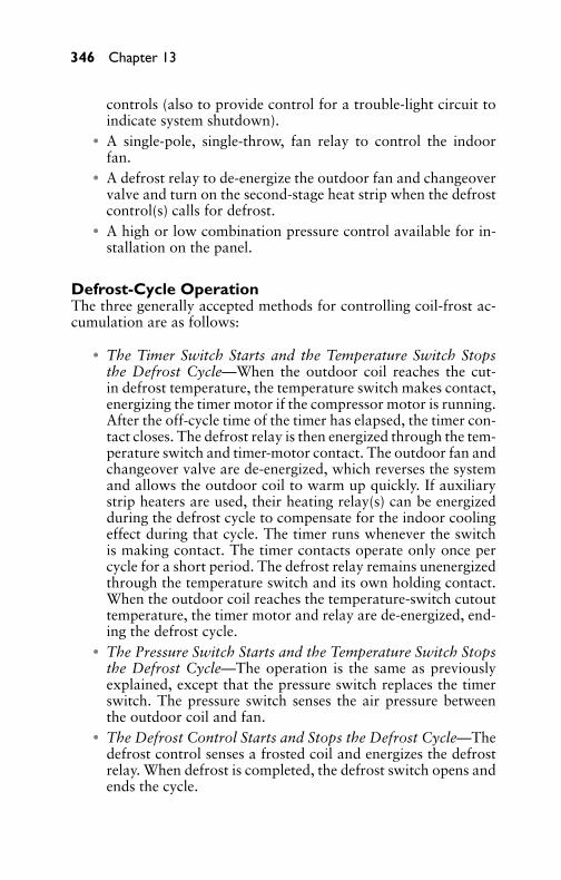
P1: GDZ/FFX P2: GDZ/FFX QC: GDZ/FFX T1: GDZ
GB076-13 GB076-Miller-Sample July 15, 2004 9:6 Char Count= 0
346 Chapter 13
controls (also to provide control for a trouble-light circuit toindicate system shutdown).� A single-pole, single-throw, fan relay to control the indoor
fan.� A defrost relay to de-energize the outdoor fan and changeover
valve and turn on the second-stage heat strip when the defrostcontrol(s) calls for defrost.� A high or low combination pressure control available for in-
stallation on the panel.
Defrost-Cycle OperationThe three generally accepted methods for controlling coil-frost ac-cumulation are as follows:
� The Timer Switch Starts and the Temperature Switch Stopsthe Defrost Cycle—When the outdoor coil reaches the cut-in defrost temperature, the temperature switch makes contact,energizing the timer motor if the compressor motor is running.After the off-cycle time of the timer has elapsed, the timer con-tact closes. The defrost relay is then energized through the tem-perature switch and timer-motor contact. The outdoor fan andchangeover valve are de-energized, which reverses the systemand allows the outdoor coil to warm up quickly. If auxiliarystrip heaters are used, their heating relay(s) can be energizedduring the defrost cycle to compensate for the indoor coolingeffect during that cycle. The timer runs whenever the switchis making contact. The timer contacts operate only once percycle for a short period. The defrost relay remains unenergizedthrough the temperature switch and its own holding contact.When the outdoor coil reaches the temperature-switch cutouttemperature, the timer motor and relay are de-energized, end-ing the defrost cycle.� The Pressure Switch Starts and the Temperature Switch Stops
the Defrost Cycle—The operation is the same as previouslyexplained, except that the pressure switch replaces the timerswitch. The pressure switch senses the air pressure betweenthe outdoor coil and fan.� The Defrost Control Starts and Stops the Defrost Cycle—The
defrost control senses a frosted coil and energizes the defrostrelay. When defrost is completed, the defrost switch opens andends the cycle.
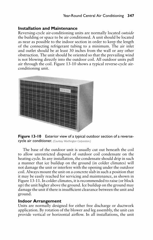
P1: GDZ/FFX P2: GDZ/FFX QC: GDZ/FFX T1: GDZ
GB076-13 GB076-Miller-Sample July 15, 2004 9:6 Char Count= 0
Year-Round Central Air Conditioning 347
Installation and MaintenanceReversing-cycle air-conditioning units are normally located outsidethe building or space to be air conditioned. A unit should be locatedas near as possible to the indoor section in order to keep the lengthof the connecting refrigerant tubing to a minimum. The air inletand outlet should be at least 30 inches from the wall or any otherobstruction. The unit should be oriented so that the prevailing windis not blowing directly into the outdoor coil. All outdoor units pullair through the coil. Figure 13-10 shows a typical reverse-cycle air-conditioning unit.
Figure 13-10 Exterior view of a typical outdoor section of a reverse-cycle air conditioner. (Courtesy Worthington Corporation.)
The base of the outdoor unit is usually cut out beneath the coilto allow unrestricted disposal of outdoor coil condensate on theheating cycle. In any installation, the condensate should drip in sucha manner that ice buildup on the ground (in colder climates) willnot damage the unit or interfere with the opening under the outdoorcoil. Always mount the unit on a concrete slab in such a position thatit may be easily reached for servicing and maintenance, as shown inFigure 13-11. In colder climates, it is recommended to raise (or blockup) the unit higher above the ground. Ice buildup on the ground maydamage the unit if there is insufficient clearance between the unit andground.
Indoor ArrangementUnits are normally designed for either free discharge or ductworkapplication. By rotation of the blower and leg assembly, the unit canprovide vertical or horizontal airflow. In all installations, the unit

P1: GDZ/FFX P2: GDZ/FFX QC: GDZ/FFX T1: GDZ
GB076-13 GB076-Miller-Sample July 15, 2004 9:6 Char Count= 0
348 Chapter 13
Figure 13-11 Typical reverse-cycle central air-conditioning installa-tion. The refrigeration unit (mounted on a sturdy concrete pad) expelsunwanted heat and is connected by piping to the cooling coil atop theforced-warm-air furnace (left). (Courtesy Carrier Corporation.)
must be mounted level to ensure proper condensate disposal. Thecabinets are well insulated inside the air-conditioned compartment.In most installations, this construction will prevent sweating on theoutside of the unit. However, in cases where blower coils are installedin attics above living quarters, or in areas where high-humidity con-ditions are prevalent, it is recommended that an insulated watertightpan with an adequate drain connection be constructed and installedunder the cabinet. This drain should extend approximately 2 inchesbeyond the unit on all sides to ensure collecting any condensateforming on the outside of the cabinet. Figure 13-12 shows duct ar-rangement for indoor and outdoor units and condensation drip paninstalled under the cabinet.
Refrigerant TubingLocations where copper tubing will be exposed to mechanical dam-age should be avoided. If it is necessary to use such locations, thetubing should be enclosed in rigid or flexible conduit. The suctionline should be insulated to prevent sweating, and horizontal lines

P1: GDZ/FFX P2: GDZ/FFX QC: GDZ/FFX T1: GDZ
GB076-13 GB076-Miller-Sample July 15, 2004 9:6 Char Count= 0
Year-Round Central Air Conditioning 349
OUTDOORUNIT
AIR DUCTS
INSULATED DRAIN PAN
TRAP
FILTER
30" MIN.
Figure 13-12 Installation procedure and duct arrangement for out-door and indoor units with vertical and horizontal discharge, respectively.
should be pitched toward the compressor unit. When the evapora-tor is higher, or not more than 10 feet lower than the condensingunit, no oil trap is required. When the evaporator is more than10 feet lower than the condensing unit, an oil trap is required in thesuction line to ensure the return of oil to the compressor.

P1: GDZ/FFX P2: GDZ/FFX QC: GDZ/FFX T1: GDZ
GB076-13 GB076-Miller-Sample July 15, 2004 9:6 Char Count= 0
350 Chapter 13
Refrigerant lines are connected as follows, using either a hard- orsoft-type solder:
1. Unsolder the sealed end of the suction and liquid lines on theevaporator unit.
2. Carefully clean the fittings and solder the refrigerant lines inplace.
3. Remove caps on the suction and liquid lines of the outdoorunit. Apply heat to the caps to remove. The caps are solderedto the fittings with soft solder.
NoteIf the cap on the suction line does not loosen readily, refrigerantoil may be present in the suction line that is conducting the heataway from the cap. To relieve the oil, drill a small hole in thesuction-line cap to allow the oil to drain out. After the oil hasdrained, the suction-line cap should then be easily loosened andremoved.
4. The liquid and suction-line service valves are usually front-seated (closed to the atmosphere). The service port is posi-tioned so that it can be used to pump down the indoor unitafter the refrigerant lines are soldered in place, without losingthe basic holding charge contained in the unit.
5. Carefully clean the suction and liquid-line fittings on the unit,and solder the refrigerant lines to these fittings. Figure 13-13shows the various stages in making a connection.
Quick-Connect CouplingsMost packaged air-conditioning units come with a complete chargeof refrigerant. The copper tubing that connects the compressor withthe evaporator is also charged to prevent any air entering the systemwhen it is installed. One way to make sure there is no air enteringthe system is to make the connections between the tubing with afull charge of refrigerant and the compressor unit with a full chargeof refrigerant simple and quick. This can be accomplished by usingtube quick-connect (TQC) couplings (see Figure 13-14).
Installation is rather simple and quick. Simply push down onthe mechanical lock for an instant, positive, leak-free connection.A cam-locking device grips uniformly (firmly, but gently) withoutdamage to steel, copper, brass, or even plastic tubes. O-ring seals onthe tube outside diameter handle the out-of-roundness conditions
P1: GDZ/FFX P2: GDZ/FFX QC: GDZ/FFX T1: GDZ
GB076-13 GB076-Miller-Sample July 15, 2004 9:6 Char Count= 0
Year-Round Central Air Conditioning 351
KNIFEDIAPHRAGMS
DIAPHRAGMS
Coupling halves before connection.
KNIFE EDGE METAL SEAL DIAPHRAGMS—FOLDED BACK
RUBBER SEAL
(A)
Coupling halves partially connected.(B)
Coupling halves connected.(C)
Figure 13-13 Refrigerant-tube couplings and methods of assembly.
of up to 2 percent. A long-life seal reduces connector maintenancecosts. It requires only a 1-inch straight tube length engagement.
The series 250 two-way shutoff couplings have an 8-ball detectlock that provides quick, positive coupling. Simply slide back thegrooved lock ring on the coupler and push together until the lockring snaps back to its locked position. It is easy to connect, andcan be manually coupled up to 200 psi. Replacement O-ring sealsprovide leak-tight shutoff.
The two-way shut-off coupling in Figure 13-15 shows how theparts are located to make it easy to couple and decouple. The

P1: GDZ/FFX P2: GDZ/FFX QC: GDZ/FFX T1: GDZ
GB076-13 GB076-Miller-Sample July 15, 2004 9:6 Char Count= 0
352 Chapter 13
9
14 15 5 1 16 4 17 2
20
18
19
321 22 23
10 8 7 12 11 6 13
1. SPRING2. SEAL3. COLLET4. SCREWS (2)5. DISC6. O RING7. SPRING8. VALVE
9. O RING10. RETAINER11. BODY12. PERCH13. SPACER14. BODY15. WASHER16. SOCKET
17. TOGGLE (2)18. BARREL19. SPRING20. HOLDER21. SLEEVE22. COLLAR23. LEVER
"TQC"ACTUAL SIZE
SERIES 250ACTUAL SIZE
Figure 13-14 Quick-connect couplings.
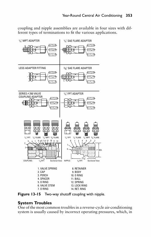
P1: GDZ/FFX P2: GDZ/FFX QC: GDZ/FFX T1: GDZ
GB076-13 GB076-Miller-Sample July 15, 2004 9:6 Char Count= 0
Year-Round Central Air Conditioning 353
coupling and nipple assemblies are available in four sizes with dif-ferent types of terminations to fit the various applications.
24
3
COUPLING– NIPPLE–Sectional View Sectional View
5 1 6 8 9 7 13 12 10 11 14 18
7
6
3 4 9 5 2
1/4" MPT ADAPTER
LESS ADAPTER FITTING 3/8" SAE FLARE ADAPTER
1/4" SAE FLARE ADAPTER
SERIES # 250 VALVECOUPLING ADAPTER
1/4" FPT ADAPTER
1/4" FPT 1/4" FLARE 1/4" MPT 3/8" FLARE 1/4" FPT 1/4" FLARE 1/4" MPT 3/8" FLARE
11/8"DIA. 1" HEX.
213/32" 21/64"1/4"FPT 1/4"FPT
1/4
5/16
3/8
1/4
5/16
3/8
1/4
5/16
3/8
1/4
5/16
3/8
1/4
5/16
3/8
1/4
5/16
3/8
1. VALVE SPRING 2. CAP 3. PERCH 4. SPACER 5. O RING 6. VALVE STEM 7. O RING
8. RETAINER 9. BODY10. O RING11. BALL12. SPRING13. LOCK RING14. RET. RING
Figure 13-15 Two-way shutoff coupling with nipple.
System TroublesOne of the most common troubles in a reverse-cycle air-conditioningsystem is usually caused by incorrect operating pressures, which, in

P1: GDZ/FFX P2: GDZ/FFX QC: GDZ/FFX T1: GDZ
GB076-13 GB076-Miller-Sample July 15, 2004 9:6 Char Count= 0
354 Chapter 13
turn, may prevent the reversing valve from shifting properly. Forexample:
� A leak in the system resulting in loss of charge� A compressor that is not pumping properly� A check valve that is leaking� A defective electrical system� Mechanical damage to the reversing valve
Before attempting to diagnose reversing-valve trouble, the fol-lowing checks on the system should be made:
1. Make a physical inspection of the valve and solenoid coil fordents, deep scratches, and cracks.
2. Check the electrical system. This is readily done by havingthe electrical system in operation so that the solenoid coil isenergized. In this condition, remove the locknut to free thesolenoid coil. Slide it partly off the stem, and notice a mag-netic force attempting to hold the coil in its normal position.By moving the coil farther off the stem, a clicking noise willindicate the return of the plunger to its de-energized position.When returning the coil to its normal position on the stem,another clicking noise indicates that the plunger responds tothe energized coil. If these conditions have not been satisfied,other components of the electrical system should be checkedfor possible trouble.
3. Check the heat-pump refrigeration system for proper opera-tion as recommended by the manufacturer of the equipment.
Reversing-Valve Troubleshooting GuideThe following troubleshooting guide shown in Table 13-1 will assistin the diagnosis of reversing-valve malfunction and suggest checksand corrections.
Nonportable Air ConditionersNonportable air-conditioning units are used in stores, restaurants,and offices and are manufactured in a large variety of cooling capac-ities designed to suit almost any requirement. Figure 13-16 showsa typical nonportable, self-contained unit. It is essentially a remotevertical-type air conditioner with the condensing unit mounted in asound-insulated enclosure.
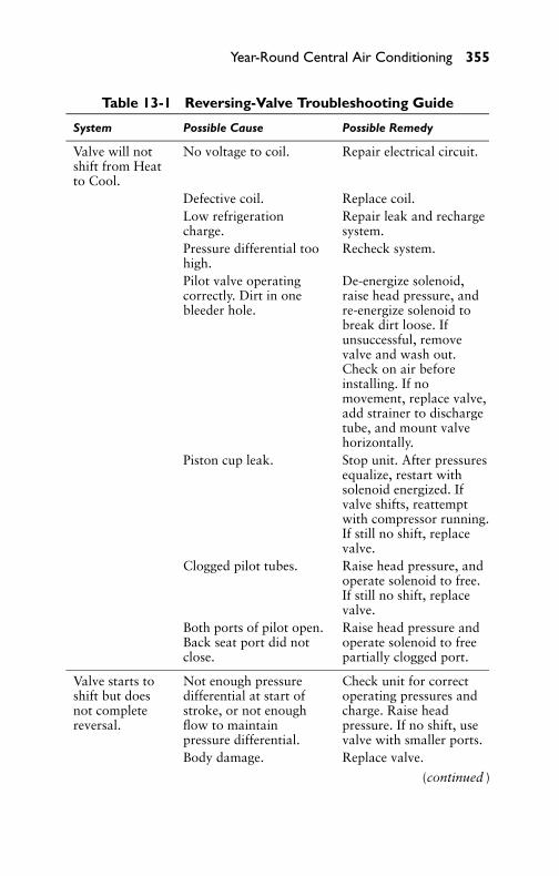
P1: GDZ/FFX P2: GDZ/FFX QC: GDZ/FFX T1: GDZ
GB076-13 GB076-Miller-Sample July 15, 2004 9:6 Char Count= 0
Year-Round Central Air Conditioning 355
Table 13-1 Reversing-Valve Troubleshooting Guide
System Possible Cause Possible Remedy
Valve will notshift from Heatto Cool.
No voltage to coil. Repair electrical circuit.
Defective coil. Replace coil.Low refrigerationcharge.
Repair leak and rechargesystem.
Pressure differential toohigh.
Recheck system.
Pilot valve operatingcorrectly. Dirt in onebleeder hole.
De-energize solenoid,raise head pressure, andre-energize solenoid tobreak dirt loose. Ifunsuccessful, removevalve and wash out.Check on air beforeinstalling. If nomovement, replace valve,add strainer to dischargetube, and mount valvehorizontally.
Piston cup leak. Stop unit. After pressuresequalize, restart withsolenoid energized. Ifvalve shifts, reattemptwith compressor running.If still no shift, replacevalve.
Clogged pilot tubes. Raise head pressure, andoperate solenoid to free.If still no shift, replacevalve.
Both ports of pilot open.Back seat port did notclose.
Raise head pressure andoperate solenoid to freepartially clogged port.
Valve starts toshift but doesnot completereversal.
Not enough pressuredifferential at start ofstroke, or not enoughflow to maintainpressure differential.
Check unit for correctoperating pressures andcharge. Raise headpressure. If no shift, usevalve with smaller ports.
Body damage. Replace valve.
(continued )

P1: GDZ/FFX P2: GDZ/FFX QC: GDZ/FFX T1: GDZ
GB076-13 GB076-Miller-Sample July 15, 2004 9:6 Char Count= 0
356 Chapter 13
Table 13-1 (continued)
System Possible Cause Possible Remedy
Both ports of pilot open. Raise head pressure, andoperate solenoid. If noshift, replace valve.
Valve hung up atmidstroke. Pumpingvolume of compressornot sufficient tomaintain reversal.
Raise head pressure, andoperate solenoid. If noshift, use valve withsmaller ports.
Apparent leakin heatingposition.
Piston needle on end ofslide leaking.
Operate valve severaltimes; then recheck. Ifexcessive leak, replacevalve.
Pilot needle and pistonneedle leaking.
Operate valve severaltimes; then recheck. Ifexcessive leak, replacevalve.
Valve will notshift from Heatto Cool.
Pressure differential toohigh.
Stop unit (will reverseduring equalizationperiod). Recheck system.
Clogged pilot tube. Raise head pressure.Operate solenoid to freedirt. If still no shift,replace valve.
Dirt in bleeder hole. Raise head pressure;operate solenoid.Remove valve and washout. Check on air beforereinstalling. If nomovement, replace valve.Add strainer to dischargetube. Mount valvehorizontally.
Piston-cup leak. Stop unit. After pressuresequalize, restart withsolenoid de-energized. Ifvalve shifts, reattemptwith compressor running.If it still will not reversewhile running, replacevalve.
Defective pilot Replace valve.

P1: GDZ/FFX P2: GDZ/FFX QC: GDZ/FFX T1: GDZ
GB076-13 GB076-Miller-Sample July 15, 2004 9:6 Char Count= 0
Year-Round Central Air Conditioning 357
FANMOTOR
CONTROLPANEL
FILTER
STARTER
WATERVALVE
GAGECONNECTION
DISCHARGEVALVE
EXPANSIONVALVE
LIQUIDFILTER
COOLINGCOILS
LIQUIDLINE VALVE
Figure 13-16 Typical, nonportable air-conditioning unit.
Units of this type may not require condenser cooling-water con-nections. If the unit is to include winter conditioning, it will alsorequire steam or hot-water piping for the heating coil and a waterconnection for the humidifier. The provision for connecting the unitto an outside air duct is usually optional. The heat generated by thecompression of refrigerant gases and that given off by the compres-sor motor is removed from the compressor compartment by meansof one of the following:� Use of a water coil in the compressor compartment� Utilization of the cold suction gases� Drawing part of the return air through the compressor com-
partment� Using an air-circulating fan on the motor shaft

P1: GDZ/FFX P2: GDZ/FFX QC: GDZ/FFX T1: GDZ
GB076-13 GB076-Miller-Sample July 15, 2004 9:6 Char Count= 0
358 Chapter 13
In water-cooled units, drain facilities must be available, and al-though window connections are not required for heat disposal, it isusually desirable to have an outside air connection for ventilationpurposes.
Construction PrinciplesWith reference to Figure 13-16 (showing a typical, self-contained,store-type air conditioner), observe that the unit is divided into threeprincipal compartments (or sections) as follows:� The acoustically treated refrigerating section, containing the
condensing unit (complete with motor), compressor, receiver,and controls.� The air-conditioning section, with the cooling centrifugal fan
and motor, fan drive, inlet grille with filter, and space for aheating coil.� The air-distributing section, or hood, with acoustical insula-
tion and air-discharge grilles.
The steel hood has air-distribution grilles on all four sides. Thetop, ends, and rear of the hood are of one-piece welded constructionwith insulation covering the air-distribution grilles. The front-grillepanel of the hood is a separate piece attached to the main hoodwith screws. A set of vertical adjustable louvers is located behindthe front-panel horizontal grilles.
It should be clearly understood that the air-conditioning unitshown in Figure 13-16 is only typical, and that arrangements andplacing of components vary, depending on the particular manufac-turer. Thus, for example, numerous units of recent make are pro-vided with a hermetically sealed compressor. They all operate on thesame principle. They have a similar refrigeration cycle. In addition,they are controlled by an easily accessible control station. Auto-matic control is provided by means of the conventional thermostat,which is actuated by the temperature of the room air entering theunit.
Plumbing ConnectionsThe only plumbing connections necessary for summer air condi-tioning are the condenser water inlet, condenser water outlet, andevaporator condensate drain. If the unit is to include winter condi-tioning, it will also require steam or hot-water piping for the heat-ing coil and a water connection for the humidifier. Condenser waterpipes enter through knockouts provided in the side of the bottomsection. For city water applications, the condenser water-inlet and-outlet connections are usually 3/4-inch standard steel or iron pipe

P1: GDZ/FFX P2: GDZ/FFX QC: GDZ/FFX T1: GDZ
GB076-13 GB076-Miller-Sample July 15, 2004 9:6 Char Count= 0
Year-Round Central Air Conditioning 359
for runs up to 50 feet. For greater lengths, 1-inch pipe is used. Theevaporator condensate drain should be 11/4-inch pipe.
The water leaving the condenser (if it is not to be reused) shouldbe piped to the sewer in accordance with local plumbing regula-tions. Many codes require an open funnel or sink discharge, andthis method is desirable from a service standpoint because it facili-tates checking performance. An automatic water-regulating valve isrequired in the inlet-water line. This valve will operate satisfactorilyon inlet-water pressures of from 25 psi to about 75 psi. A shutoffwater-regulating valve is required in the inlet and outlet-water pipes,respectively, as shown in Figure 13-17.
CABINET
WATER TODRAIN
CITY WATERIN
CONDENSATE TODRAIN
Figure 13-17 Plumbingconnections for awater-cooled condensingunit.
Water-Cooling TowerIn locations where the use of city water is restricted, circulatingwater from a cooling tower may be used for condenser cooling. Thequantity of water circulated through water-cooling towers usuallyvaries between 3 and 5 gal per min per ton of refrigeration, the largerquantity being used when the lowest possible water temperature isdesired. The total head (in feet) against which the pump in a balancedsystem must work is composed of the following:� Condenser head� Head required at base of tower� Friction head in piping and fitting
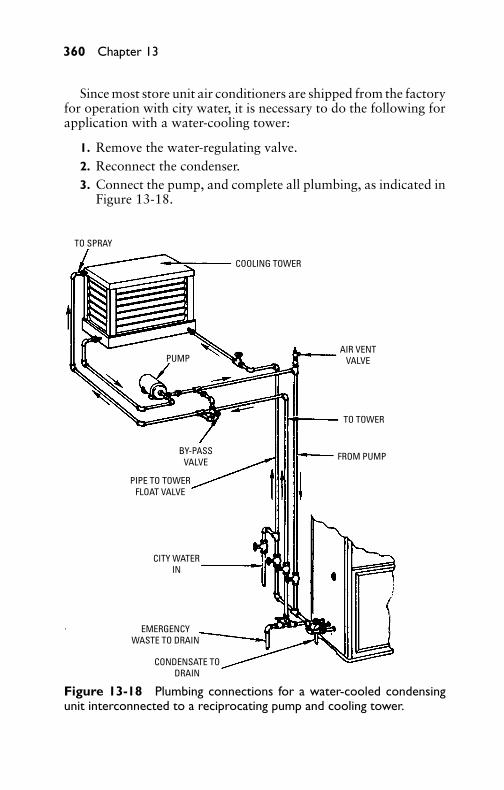
P1: GDZ/FFX P2: GDZ/FFX QC: GDZ/FFX T1: GDZ
GB076-13 GB076-Miller-Sample July 15, 2004 9:6 Char Count= 0
360 Chapter 13
Since most store unit air conditioners are shipped from the factoryfor operation with city water, it is necessary to do the following forapplication with a water-cooling tower:
1. Remove the water-regulating valve.2. Reconnect the condenser.3. Connect the pump, and complete all plumbing, as indicated in
Figure 13-18.
TO SPRAY
PUMP
COOLING TOWER
BY-PASSVALVE
PIPE TO TOWERFLOAT VALVE
CITY WATERIN
EMERGENCYWASTE TO DRAIN
CONDENSATE TODRAIN
FROM PUMP
TO TOWER
AIR VENTVALVE
Figure 13-18 Plumbing connections for a water-cooled condensingunit interconnected to a reciprocating pump and cooling tower.
P1: GDZ/FFX P2: GDZ/FFX QC: GDZ/FFX T1: GDZ
GB076-13 GB076-Miller-Sample July 15, 2004 9:6 Char Count= 0
Year-Round Central Air Conditioning 361
Heating CoilsHeating coils are commonly supplied by the manufacturer as extraequipment for field installation directly above the cooling unit. Thecontrols for heating are generally purchased locally. If space permits,the heater pipes can be brought in from the sides of the cabinet di-rectly opposite the coil connections by drilling holes in the cabinetand notching the side-access plates as necessary. This arrangement,however, is not as desirable as the other from the appearance stand-point.
Heating coils, as supplied by the manufacturer, are usually pro-vided with two 11/2-inch female pipe taps in the inlet and outletheaders. The coil should be installed with these openings below thecenterline of the coil to allow proper drainage. In addition, the coilmust be sloped downward approximately 3/8-inch in the direction ofthe steam or water flow. The coil outlet is always brought into theopposite header from the inlet and in the opposite location front toback, so that the heating medium passes through the coil in a zig-zagpath to obtain the most satisfactory distribution. For hot water, amanual-type vent valve is used. For steam, an automatic vent valveis used.
In a one-pipe steam system, a bypass connection around theheater is required to return the condensed steam to the supply riser.This connection should pass down from the outlet header at oneend and around the bottom of the cooling coil and into the sup-ply pipeline on the opposite end. It is necessary that this line beproperly sized to maintain a water seal against the incoming steampressure, and that it be tapped into the supply riser for returning thecondensate.
Suspended-Type Air ConditionersSuspended-type air conditioners are used in stores, garages, and es-tablishments with limited floor space. They are designed to suit vari-ous applications requiring dehumidification, cooling, and/or heatingcombinations, as conditions require.
Suitable locations for store units are placement above the doorof restaurants or above the kitchen floor. They may also be incor-porated in wall structures, particularly where false walls are em-ployed or where the wall is a partition into another room of thesame establishment. Because of the weight of the unit, careful con-sideration must be given to the strength of the location where it willbe installed. Some smaller suspended-type units use propeller fanswith trailing-edge blades in order to obtain the required pressurecharacteristics.

P1: GDZ/FFX P2: GDZ/FFX QC: GDZ/FFX T1: GDZ
GB076-13 GB076-Miller-Sample July 15, 2004 9:6 Char Count= 0
362 Chapter 13
CasingsSuspended-type air-conditioner casings are usually made of sheetmetal supported by suitable angle frames, with removable panelspermitting access to the interior components for proper mainte-nance. The compressor compartment is normally insulated to pre-vent noise from escaping into the room. Drain pans are usually madeof 14-gage or heavier sheet metal and should be hot-dip galvanizedafter fabrication to resist corrosion. The drain connections should bereadily accessible for cleaning. In air-conditioner work, they shouldbe properly sized and trapped according to plumbing regulations inthe area of installation.
CoilsThe cooling and dehumidifying coils used in suspended-type air con-ditioners do not differ in any important respect from those used inthe self-contained units previously described. The face of the coilarea is usually fixed, and the number of coils in depth in the airflowdirection determines the capacity. Figure 13-19 shows a typical in-stallation. Heating coils of unit air conditioners are normally of theconventional blast coil-type and are usually furnished separately forinstallation on the premises. They usually match the cooling coilsin face area and may be one or two rows in depth, depending onheating requirements.
EVAPORATOR
AIR FLOW
PRESSURE EQUALIZEREXPANSION
VALVELIQUID
LINE
REFRIGERANTSTRAINER
SUCTIONLINE
DISTRIBUTORTUBES
CONTROLBULB
Figure 13-19 Cooling-coil arrangement of a typical suspended-typeair conditioner.
P1: GDZ/FFX P2: GDZ/FFX QC: GDZ/FFX T1: GDZ
GB076-13 GB076-Miller-Sample July 15, 2004 9:6 Char Count= 0
Year-Round Central Air Conditioning 363
FiltersAir filters of the viscous domestic type are usually furnished onsuspended-type air conditioners. These may be the throwaway type,although cleanable filters may be used on the larger units. Therefrigerant may be controlled by the conventional thermostaticexpansion valve or restrictor tubing, as conditions dictate. Wallthermostats are commonly used for temperature control in conjunc-tion with solenoid valves. The use of solenoid valves in the liquidline between the strainer and expansion valve depends on whetheror not the unit is to be installed in a multiple system.
Where the unit is connected to a single dome-head condensingunit, the thermostat and manual switch may be connected directly tothe low-pressure switch circuit. Solenoid-valve refrigerant control,however, is usually employed where these units are used in conjunc-tion with the piston-valve–type compressor to prevent flooding ofthe crankcase during the off cycle of the compressor.
ControlsWhere the suspended-type air conditioner is equipped with blast-type heating coils, two methods of automatic control are generallyused: (1) the control of steam flow and air temperature by automaticmodulating valves, and (2) the control of temperature by automaticmodulating face and bypass dampers. Both control methods areused to a considerable extent, but the modulating-valve method ispreferred.
Modulating valves proportion, or meter, the steam supply to thecoils according to the exact heating demand at any time. They pro-vide heating as required by the modulating thermostat to maintainthe desired conditions. The quantity of air passing through the coilis constant. Face and bypass dampers are actuated by a modulat-ing motor, which is controlled by a modulating thermostat. Thedampers are positioned to permit the quantity of air necessary formaintaining the desired temperature to pass through the coils forheating. The air quantity through the coils changes as the demandchanges with the remainder of the air being bypassed. Finally, whenno heating is required, the face dampers close and all air is bypassed.It is usual practice to provide an automatically operated steam valvefor disconnecting the steam supply from the coil bank when the facedampers are closed.
Air-Conditioning Troubleshooting GuideThe troubleshooting guide shown in Table 13-2 will assist introubleshooting air-conditioning and self-contained air-conditioner

P1: GDZ/FFX P2: GDZ/FFX QC: GDZ/FFX T1: GDZ
GB076-13 GB076-Miller-Sample July 15, 2004 9:6 Char Count= 0
364 Chapter 13
Table 13-2 Self-Contained Air-ConditionerTroubleshooting Guide
System Possible Cause Possible Remedy
Unit fails tostart.
Starting switch off. Place starting switch in startposition.
Reset button out. Push reset button.Power supply off. Check voltage at connection
terminals.Loose connection inwiring.
Check external and internalwiring connections.
Valves closed. See that all valves areopened.
Motor humsbut fails tostart.
Motor single-phasingon three-phase circuits.
Test for blown fuse andoverload trip out.
Belts too tight. See that the motor is fullfloating on a trunnion base.See that the belts are in thepulley groove and notbinding.
No oil in bearings.Bearings tight fromlack of lubrication.
Use proper oil for motor.
Unit fails tocool.
Thermostat set wrong. Check thermostat setting.
Fan not running. Check fan-motor electricalcircuit. Also determine iffan blade and motor shaftrevolve freely.
Coil frosted. Dirty filters. Restrictedairflow through unit may becaused by some obstructionat air grille. Fan notoperating. Attempting tooperate unit at too low acoil temperature.
Unit runscontinuouslybut no cooling.
Shortage of refrigerant. Check liquid-refrigerantlevel. Test for leaks, repair,and add refrigerant toproper level.
(continued )

P1: GDZ/FFX P2: GDZ/FFX QC: GDZ/FFX T1: GDZ
GB076-13 GB076-Miller-Sample July 15, 2004 9:6 Char Count= 0
Year-Round Central Air Conditioning 365
Table 13-2 (continued)
System Possible Cause Possible Remedy
Unit cycles toooften.
Thermostat differentialtoo close.
Check differential setting ofthermostat and adjustsetting.
Unit vibrates. Not sitting level. Level all sides.Shipping bolts notremoved.
Remove all shipping boltsand steel bandings.
Belts jerking. Motor not floating freely.Unit suspensionsprings not balanced.
Adjust unit suspension untilunit ceases vibrating.
Condensateleaks.
Drain lines notproperly installed.
Drainpipe sizes, proper fallin drain line, traps, andpossible obstruction fromforeign matter should bechecked.
Organic slimeformation in pan anddrain lines andsometimes present onevaporator fins.
This formation is largelybiological and usuallycomplex in nature. Differentlocalities produce differenttypes. It is largely a localproblem. To combat it, itshould be observed as such.Periodic cleaning will tendto reduce the trouble, butwill not eliminate it.Filtering air thoroughly willalso help. Sometimescapacity must be sacrificedwhen doing this.
Noisycompressor.
Too much vibration inunit.
Check for point of vibrationin set-up.
Slugging oil. Low suction pressure.Bearing knock. Liquid in crankcase.Oil level low incrankcase.
Pump down system and addoil if too low.
P1: GDZ/FFX P2: GDZ/FFX QC: GDZ/FFX T1: GDZ
GB076-13 GB076-Miller-Sample July 15, 2004 9:6 Char Count= 0
366 Chapter 13
systems. It should be noted, however, that at times the trouble maydiffer from that given in this section. Experience will usually revealthe exact cause, after which the remedy and its correction may becarried out.
SummaryCentral air conditioning has the advantage of servicing severalrooms with lower cost than several self-contained single-room units.During the winter, central air conditioning is required to warm theair to a comfortable temperature. During the summer, it is requiredto cool the air, plus humidify and dehumidify, as required.
Year-round air-conditioning systems may be classified as gas-compression, absorption, and steam-jet vacuum. A gas-compressionair-conditioning system is a simple refrigeration system employing acompressor to remove low-pressure refrigerant enclosed in the low-pressure side and transfer it to the high-pressure side of the system.The absorption system is one in which the refrigerant gas in theevaporator is taken up by an absorber and released in a generatorupon application of heat. A steam-jet system is vacuum refrigerationin which high pressure is supplied through a nozzle acting to ejectwater from the evaporator.
The basic difference between absorption- and compression-typeair conditioning is that the absorption system uses heat or steam tocirculate the refrigerant, while the compression system employs acompressor to circulate the refrigerant.
Review Questions1. What are the fundamental requirements for year-round air
conditioning?2. What are the principal advantages of year-round air condi-
tioning?3. What is meant by the mixing chamber and what is its purpose?4. What means are used for cooling in year-round air condition-
ing?5. Describe blower types and methods of installation in an air-
conditioning system.6. What is the function of air filters in air conditioning?7. Describe what is meant by zone control, and state its principal
advantages.8. What are the fundamental requirements in selecting a year-
round air conditioner?

P1: GDZ/FFX P2: GDZ/FFX QC: GDZ/FFX T1: GDZ
GB076-13 GB076-Miller-Sample July 15, 2004 9:6 Char Count= 0
Year-Round Central Air Conditioning 367
9. In what respect does an absorption-type air conditioner differfrom that of a conventional compression system?
10. Describe the principles of operation of an absorption-type airconditioner.
11. Describe the operating principles of a reverse-cycle air-conditioning system.
12. What is the function of the reversing valve?13. What is the vacuum-pump method of purging the reverse-cycle
air-conditioning unit?14. What are the most common troubles in reverse-cycle air-
conditioning systems?15. What is meant by a self-contained air-conditioning unit?16. Describe the function and operation of a window-type air con-
ditioner.17. Describe the electrical control system of a window-type air
conditioner.18. Describe the plumbing methods in a nonportable air condi-
tioner equipped with a water-cooled condenser.19. Where are heating coils normally located in nonportable year-
round air conditioners?20. What type of air conditioner is usually found in stores and
garages with limited floor space?

P1: GDZ/FFX P2: GDZ/FFX QC: GDZ/FFX T1: GDZ
GB076-13 GB076-Miller-Sample July 15, 2004 9:6 Char Count= 0
368

P1: GDZ/FFX P2: GDZ/FFX QC: GDZ/FFX T1: GDZ
GB076-14 GB076-Miller-Sample July 15, 2004 5:12 Char Count= 0
Chapter 14Automobile Air ConditioningThe automobile air conditioner is no different from any other typeof air-conditioning system. The major components (such as the com-pressor, condenser, and evaporator) are utilized in primarily the samemanner as the common room air conditioner. Certain variations anddifferences are unique to automobile air-conditioning systems (suchas the power source, method and type of controls, and componentdesign). Figure 14-1 shows a typical automobile air-conditioninginstallation. Power is supplied to the compressor directly from thecrankshaft of the engine by means of a V-belt assembly and a seriesof pulleys, as shown in Figure 14-2.
Two temperature-control methods are used most often by auto-motive air-conditioning manufacturers: the magnetic (or electric)clutch and the refrigerant-flow control. Normally, the magneticclutch utilizes a stationary electromagnet, which is attached to thecompressor. The brushes and collector rings can be eliminated withthis arrangement since the electromagnet does not rotate.
When a high temperature is present in the passenger compartmentof the car, a thermostat (set by the driver to a specified temperature)closes the electrical circuit that connects the battery power supplyto the stationary magnetic field. This field exists around the electro-magnet that is mounted on the shaft of the compressor. A continu-ously rotating clutch plate then engages the compressor drive shaftand causes the compressor to operate at a higher rate of speed. Thisclutch plate is mechanically attached to the compressor flywheel,which is driven by the V-belt assembly. When the interior of the carreaches the low-temperature setting of the thermostat, the thermo-stat will open the electrical circuit. The current will cease flowing,and the clutch plate will disengage the flywheel from the compres-sor. The flywheel will continue to rotate freely until the interiorcompartment temperature again rises above the thermostat setting.Figure 14-3 shows a typical older model compressor with magnetic-clutch assembly.
The refrigerant-flow control maintains a constant rate of re-frigerant flow in the refrigeration system. This equalizing effect isextremely necessary since the compressor does not operate at aconstant rate of speed. The control is located in the suction (orlow) side of the refrigeration system. Its spring-loaded bellows areresponsive to pressure changes that take place in the system. Witha decrease in pressure, which accompanies a proportional decreasein interior temperature, the valve closes and thereby restricts the
369

P1: GDZ/FFX P2: GDZ/FFX QC: GDZ/FFX T1: GDZ
GB076-14 GB076-Miller-Sample July 15, 2004 5:12 Char Count= 0
EVAP
ORAT
ORAS
SEM
BLY
BLOW
ER
HEAT
ER H
OSE
HEAT
ER H
OSE
HEAT
ER H
OSE
SUCT
ION
HOS
E
SUCT
ION
THR
OTTL
EVA
LVE
HOSE
-VAC
.(S
OURC
E)
DISC
HARG
E HO
SE A
SSY.
COM
PRES
SOR
CON
DEN
SER
RECE
IVER
DEHY
DRAT
OR
Fig
ure
14-1
Typi
cala
utom
obile
air-
cond
ition
ing
syst
emsh
owin
glo
catio
nof
mai
nco
mpo
nent
s.(C
ourt
esy
Gen
eral
Mot
ors
Corp
orat
ion.
)
370

P1: GDZ/FFX P2: GDZ/FFX QC: GDZ/FFX T1: GDZ
GB076-14 GB076-Miller-Sample July 15, 2004 5:12 Char Count= 0
Automobile Air Conditioning 371
AC
AC
CS
CS
PS
PS
WP
WP
I
CS = CRANKSHAFT; A = ALTERNATOR; WP = WATER PUMP; PS = POWER STEERING;AC = AIR-CONDITIONER COMPRESSOR; I = IDLER PULLEYS
I
A
A
I
I
Figure 14-2 Typical belt arrangement in a modern automobile engine.(Courtesy General Motors Corporation.)
refrigerant flow. This restriction affects the operation of the systemby limiting or completely halting the cooling effect, as the case maybe. The refrigerant-flow control is also responsive to the flow rateof the refrigerant. The valve is closed by an increase in flow rate.This increase causes the refrigerant pressure surrounding the valvestem to decrease and thereby affect the control valve, independentof the low-side pressure.

P1: GDZ/FFX P2: GDZ/FFX QC: GDZ/FFX T1: GDZ
GB076-14 GB076-Miller-Sample July 15, 2004 5:12 Char Count= 0
REAR
HEA
D
OIL
PUM
PGE
ARS
REAR
DIS
CHAR
GEVA
LVE
PLAT
E SUCT
ION
REE
DVA
LVE
O-RI
NG
SEAL
OIL
INLE
T TU
BE REAR
NEE
DLE
THRU
STBE
ARIN
G&
RAC
ES
FRON
TN
EEDL
ETH
RUST
BEAR
ING
& R
ACESSH
ELL SH
AFT
NEE
DLE
BEAR
INGSU
CTIO
N R
EED
VALV
E
FRON
T DI
SCHA
RGE
VALV
E PL
ATE
O-RI
NG
SEAL
O-RI
NG
SEAL
O-RI
NG
SEAL
FRON
T HE
AD
SHAF
T SE
AL
SEAL
SEA
T
SEAL
SEA
TRE
TAIN
ERRI
NG
BEAR
ING
RETA
INER
WIR
E
PULL
EYRE
TAIN
ERRI
NG
RETA
INER
RIN
G
DRIV
E PL
ATE
ASSY
.
BEAR
ING
DRIV
EKE
Y
PULL
EYRE
TAIN
ERRI
NG CO
IL &
HOUS
ING
REAR
CYL
INDE
RHA
LFSW
ASH
PLAT
EFR
ONT
CYLI
NDE
RHA
LFSH
OE D
ISC
DRIV
E BA
LLPI
STON
RIN
G
SPAC
ER NUT
SHAF
T
PIST
ON
Fig
ure
14-3
Sect
iona
lvie
wof
anai
r-co
nditi
oner
com
pres
sor
with
doub
le-a
ctio
npi
ston
desi
gnan
dm
agne
tic-c
lutc
hco
ll.(C
ourt
esy
Gen
eral
Mot
ors
Corp
orat
ion.
)
372
P1: GDZ/FFX P2: GDZ/FFX QC: GDZ/FFX T1: GDZ
GB076-14 GB076-Miller-Sample July 15, 2004 5:12 Char Count= 0
Automobile Air Conditioning 373
Another type of cooling control is the hot-gas bypass valve. Thiscontrol regulates the temperature by constantly varying the amountof refrigerant allowed to bypass the cooling network, thereby in-creasing or decreasing the cooling capacity of the system. Utiliza-tion of this control valve permits constant compressor operation andprovides an evaporator antifreeze device. By regulating the internalpressure of the evaporator, the hot-gas valve affects the cooling ca-pacity of the evaporator and prevents the pressure from decreas-ing to a pressure (29.5 psi) that will cause the evaporator core tofreeze. If this freeze-up occurs, the evaporator will not function andthe cooling effect of the air conditioner will be greatly lowered orhalted completely. The reason the evaporator will not function un-der these conditions is because of the air not passing through theevaporator core to provide the necessary cooling in the interior ofthe automobile.
Sealed systems are highly improbable for use on automobiles.This is because all systems are presently powered by the enginecrankshaft as an external source. The typical compressor used inthe automobile refrigeration system has a large refrigerating capacitycompared with the average room air conditioner (15,000 to 20,000Btu/hr as opposed to 6000 to 10,000 Btu/hr). This large coolingcapacity is primarily due to the large bore-and-stroke design of theautomotive compressor in older models; and it is a necessity for au-tomobiles because of the temperature range and poor insulation ofthe car interior.
The refrigerant most commonly used in automobile air-condi-tioning systems was Freon-12. The newer refrigerant, R-134a is nowused in all automobile and truck cooling systems for air-conditioningpurposes. Extreme caution should be exercised when working on ornear the refrigeration system. Freon-12 becomes a highly poisonousgas when it contacts an open flame. A poison gas (phosgene), whichwas used in World War I, is produced by Freon when the chlorine isreleased. It can be detected in minute amounts by smell. It smells likenewly mown hay. For this reason, the system should be completelydischarged when any repairs or replacements are made on the re-frigeration unit. The newer refrigerants do not produce this hazard.
Air-Conditioning System OperationCool refrigerant gas is drawn into the compressor from the evapo-rator and pumped from the compressor to the condenser under highpressure (see Figure 14-4). This high-pressure gas will also have ahigh temperature after being subjected to compression. As this gaspasses through the condenser, the high-pressure, high-temperaturegas rejects its heat to the outside air as the air passes over the surfaces
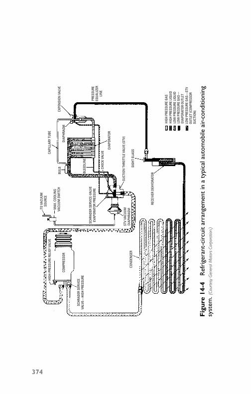
P1: GDZ/FFX P2: GDZ/FFX QC: GDZ/FFX T1: GDZ
GB076-14 GB076-Miller-Sample July 15, 2004 5:12 Char Count= 0
HIGH
-PRE
SSUR
E RE
LIEF
VAL
VE
COM
PRES
SOR
SCHR
ADER
SER
VICE
VALV
E—HI
GH P
RESS
URE
CON
DEN
SER
STV
VACU
UMDI
APHR
AGM
SCHR
ADER
SER
VICE
-VAL
VEEV
APOR
ATOR
PRE
SSUR
E
CHEC
K VA
LVE
BLEE
DLIN
E
TO V
ACUU
MSO
URCE
MAX
. COO
LIN
GVA
CUUM
SW
ITCH
BULB
CAPI
LLAR
Y TU
BE
EVAP
ORAT
OR
RECE
IVER
DEH
YDRA
TOR
SIGH
T GL
ASS
SUCT
ION
THR
OTTL
E VA
LVE
(STV
)
EXPE
NSI
ON V
ALVE
DIAP
HRAG
M
PRES
SURE
EQUA
LIZE
RLI
NE
LOW
PRE
SSUR
E GA
S—EV
APOR
ATOR
OUT
LET
LOW
PRE
SSUR
E GA
S—ST
VOU
TLET
(COM
PRES
SOR
SUCT
ION
)
HIGH
PRE
SSUR
E GA
SHI
GH P
RESS
URE
LIQU
IDLO
W P
RESS
URE
LIQU
ID
Fig
ure
14-4
Ref
rige
rant
-cir
cuit
arra
ngem
ent
ina
typi
cala
utom
obile
air-
cond
ition
ing
syst
em. (
Cour
tesy
Gen
eral
Mot
ors
Corp
orat
ion.
)
374

P1: GDZ/FFX P2: GDZ/FFX QC: GDZ/FFX T1: GDZ
GB076-14 GB076-Miller-Sample July 15, 2004 5:12 Char Count= 0
Automobile Air Conditioning 375
of the condenser. The cooling of the gas causes it to condense intoa liquid refrigerant. The liquid refrigerant, still under high pressure,passes from the bottom of the condenser into the receiver dehy-drator. The receiver acts as a reservoir for the liquid. The liquidrefrigerant flows from the receiver dehydrator to the thermostaticexpansion valve. The thermostatic expansion valve meters the high-pressure refrigerant flow into the evaporator. Since the pressure inthe evaporator is relatively low, the refrigerant immediately beginsto boil. As the refrigerant passes through the evaporator, it contin-ues to boil, drawing heat from the surface of the evaporator corewarmed by air passing over the surfaces of the evaporator core.
In addition to the warm air passing over the evaporator rejectingits heat to the cooler surfaces of the evaporator core, any moisturein the air condenses on the cool surface of the core, resulting in cooldehydrated air passing into the inside of the car. The gas that leavesthe evaporator has been completely vaporized and is slightly super-heated. Superheat is an increase in temperature of the gaseous refrig-erant above the temperature at which the refrigerant vaporized. Thepressure in the evaporator is controlled by the suction-throttle valve.Refrigerant vapor passing through the evaporator flows through thesuction-throttle valve and is returned to the compressor, where therefrigeration cycle is repeated.
Component DescriptionThe problems encountered in automobile air conditioning will per-haps be understood by a thorough study of the basic componentscomposing the system. (See Figure 14-4 to review the typical com-ponents of an automobile air-conditioning unit.)
CompressorsIn the early days of automobile air conditioning, modified commer-cial-type compressors were used. Because of the increase in enginespeed, the design and development of precision high-speed compres-sors became necessary. All air-conditioning system compressors arepresently driven by a belt from the engine crankshaft. The compres-sor speed varies with the speed of the automobile engine, which isconsiderable. For example, at idling speeds, the compressor turnsat a rate of about 400 rpm and develops a refrigerating effect inthe area of 3/4 ton. In an automobile traveling 55 mph, this samecompressor may be turning as high as 3500 rpm and developing ca-pacities in the neighborhood of 3 to 31/2 tons. This varying capacityhas dictated the design of present automotive control systems.
This high-speed operation has been accommodated by the in-troduction of the rotary compressor. The new refrigerant R-134a

P1: GDZ/FFX P2: GDZ/FFX QC: GDZ/FFX T1: GDZ
GB076-14 GB076-Miller-Sample July 15, 2004 5:12 Char Count= 0
376 Chapter 14
(a hydrofluorocarbon) is a non–ozone-depleting compound that isenvironmentally friendly. The new refrigerant does require a higherpressure to accomplish the same cooling as Freon. The main concernis the high pressure of the new refrigerant. Checking the pressureand leaks at connections are of top priority today in troubleshootingany system. New equipment to detect leaks has also been developed.
To obtain a more favorable speed characteristic, a different solu-tion to the problem could be utilized, such as a drive shaft take-offor an electric-motor drive through an alternator. Although someof these methods of operating the compressor might prove moredesirable in forms of operating efficiency, the additional cost of ap-plication (as well as space requirement) is, without doubt, an im-portant consideration.
The compressor has two functions:� To pump refrigerant through the system� To raise the pressure of the refrigerant gas received from the
cooling coil so that it will condense more readily and give upheat as it passes through the condensing coil
A typical automotive air-conditioning compressor (six-cylinder,rotary, double-action piston-type) is shown in Figure 14-3. The reed-type suction and discharge valves are mounted in a valve platebetween the cylinder assembly and the head at the end of thecompressor. The ends are connected with each other by gas-tightpassageways that direct refrigerant gas to a common output. Eachcylinder head contains suction and discharge cavities. In addition,the reed head contains an oil-pump cavity in the center of the suctioncavity to house the oil-pump gears, which are driven by the com-pressor main shaft. The suction cavity is in the center and indexeswith the suction reeds. The discharge cavity is around the outsideand indexes with the discharge needs.
These cavities are separated from each other with a Teflon sealmolded to the cylinder head. The discharge cavity is sealed fromthe outside of the compressor by an O-ring seal, which rests in achambered relief in the cylinder head and compresses against thecompressor body. An oil pump mounted at the rear of the compres-sor picks up oil from the bottom of the compressor and pumps it tothe internal parts. The inner gear fits over a matching D flat on themain shaft. The outer driven gear has internal teeth that mesh withthe external teeth on the inner drive gear.
CondensersAir-conditioning condensers are similar to ordinary automobile ra-diators but are designed to withstand much higher pressure. A

P1: GDZ/FFX P2: GDZ/FFX QC: GDZ/FFX T1: GDZ
GB076-14 GB076-Miller-Sample July 15, 2004 5:12 Char Count= 0
Automobile Air Conditioning 377
condenser is normally mounted in front of the car radiator so that itreceives a high volume of air. Air passing over the condenser coolsthe hot high-pressure refrigerant gas, causing it to condense intolow-pressure liquid refrigerant.
Receiver-DehydratorThe purpose of the receiver-dehydrator assembly is to ensure a solidcolumn of liquid refrigerant to the thermostatic expansion valve atall times (provided the system is properly charged). The dehydrator(drier) part of the assembly is to absorb any moisture that might bepresent in the system after assembly. It traps foreign material thatmay have entered the system during assembly. A liquid indicatoror sight glass is a part of most systems, and is an integral part ofthe outlet pipe of the receiver dehydrator. The appearance of bub-bles or foam in the sight glass when the ambient temperature ishigher than 70◦F indicates air or a shortage of refrigerant in thesystem.
Thermostatic Expansion ValvesThe function of the thermostatic expansion valve is to automaticallyregulate the flow of liquid refrigerant into the evaporator in accor-dance with the requirements of the evaporator. The valve is locatedat the inlet to the evaporator core. It consists essentially of a cap-illary bulb and tube connected to an operating diaphragm (sealedwithin the valve itself) and an equalizer line connecting the valveand low-pressure suction-throttling valve outlet. The thermal bulbis attached to the evaporator-outlet pipe.
The thermostatic expansion valve is the dividing line in the sys-tem between high-pressure liquid refrigerant supplied from the re-ceiver, and relatively low-pressure liquid and gaseous refrigerant inthe evaporator. It is designed so that the temperature of the refrig-erant at the evaporator outlet must have 4◦F of superheat beforemore refrigerant is allowed to enter the evaporator. (Superheat is anincrease in temperature of the gaseous refrigerant above the temper-ature at which the refrigerant vaporizes.)
A capillary tube filled with carbon dioxide and the equalizer lineprovide temperature regulation of the expansion valve. The cap-illary tube is fastened to the low-pressure refrigerant pipe comingout of the evaporator so that it samples the temperature of the re-frigerant at this point to the expansion valve. If the temperaturedifferential between the inlet and outlet decreases below 4◦F, theexpansion valve will automatically reduce the amount of refrigerantentering the evaporator. If the temperature differential increases, theexpansion valve will automatically allow more refrigerant to enter

P1: GDZ/FFX P2: GDZ/FFX QC: GDZ/FFX T1: GDZ
GB076-14 GB076-Miller-Sample July 15, 2004 5:12 Char Count= 0
378 Chapter 14
the evaporator. Figure 14-5 shows a typical thermostatic expansionvalve.
VALVE SEATVALVE
NYLON VALVE INSERT
INLETFILTER SCREEN
CAPILLARY TUBE
DIAPHRAGM DISC
OPERATINGPIN
OPERATINGDIAPHRAGM
EQUALIZER LINETO STV OUTLET
ADJUSTING SPRING WASHERADJUSTING NUT
TO EVAPORATOR
ADJUSTING SPRING
Figure 14-5 Typical internally adjusted automobile air-conditioningthermostatic expansion valve. (Courtesy General Motors Corporation.)
The temperature of the air passing over the evaporator core deter-mines the amount of refrigerant that will enter and pass through theevaporator. When the air is very warm, the heat transfer from the airto the refrigerant is great and a greater quantity of refrigerant is re-quired to cool the air and to achieve the proper superheat on therefrigerant gas leaving the evaporator. When the air passing over theevaporator is cool, the heat transfer is small and a smaller amountof refrigerant is required to cool the air and achieve the proper su-perheat on the refrigerant gas leaving the evaporator.
A mechanical adjusting nut located within the valve is providedto regulate the amount of refrigerant flow through the valve. Whenadjusted, the spring seat moves to increase or decrease the tensionon the needle-valve-carriage spring. By varying the tension on thisspring, it is possible to regulate the point at which the needle valvebegins to open or close, thereby regulating refrigerant flow into theevaporator. Since this adjustment feature is inside the valve, no ex-ternal adjustment is possible. All valves are preset at the time ofmanufacture.
When the air-conditioning system has not been operating, allpressures within the thermostatic expansion-valve assembly will

P1: GDZ/FFX P2: GDZ/FFX QC: GDZ/FFX T1: GDZ
GB076-14 GB076-Miller-Sample July 15, 2004 5:12 Char Count= 0
Automobile Air Conditioning 379
have equalized at the ambient (surrounding air) temperature. Thus,pressure above and below the operating diaphragm and at the in-let and outlet side of the valve will be equal. Pressure under thediaphragm is evaporator pressure. It reaches this area by means ofclearance around the operating pins, which connect the area un-der the diaphragm with the evaporator-pressure area. While pres-sures in the expansion valve are almost equal, the addition of thevalve-adjusting-spring pressure behind the needle will hold the nee-dle valve over to close the needle-valve orifice.
When the air-conditioning system first begins to operate, the com-pressor will immediately begin to draw refrigerant from the evapo-rator, lowering the pressure in the evaporator and in the area underthe operating diaphragm. As the pressure in this area decreases, thepressure above the diaphragm exerted by the carbon dioxide in thecapillary tube will overcome spring pressure and push the diaphragmagainst the operating pins, which, in turn, will force the needle offits seat. Refrigerant will then pass through the expansion valve intothe evaporator, where it will boil at a temperature corresponding tothe pressure in the evaporator. This will begin to cool the air passingover the evaporator, as well as the evaporator-outlet pipe.
The valve-adjusting spring is calibrated so that the pressure ofthe refrigerant in the evaporator-outlet pipe and equalizer line tothe valve (plus the spring force) will equal the force above the op-erating diaphragm when the temperature of the refrigerant in theevaporator outlet is 4◦F above the temperature of the refrigerantentering the evaporator. In other words, the refrigerant should re-main in the evaporator long enough to completely vaporize and thenwarm (superheat) to 4◦F.
If the temperature differential begins to go below 4◦F (outletpipe too cold), carbon dioxide pressure in the capillary tube and thearea above the diaphragm will decrease, allowing the valve-adjustingspring to move the needle valve toward its seat, closing off the flowof refrigerants past the needle valve. If the temperature differentialbegins to go above 4◦F (outlet pipe too warm), the pressure in thecapillary tube and the area above the operating diaphragm will in-crease, pushing this diaphragm against the operating pins to open theneedle valve further, admitting more refrigerant to the evaporator.
The equalizer line permits the suction-throttle-valve-outlet pres-sure to be imposed on the expansion valve diaphragm, thus over-riding its normal control of liquid refrigerant. As the compressorcapacity becomes greater than the evaporator load, the drop in com-pressor suction-line pressure forces the expansion valve to floodliquid through the evaporator and the suction-throttle valve,thus preventing the suction pressure from dropping below a

P1: GDZ/FFX P2: GDZ/FFX QC: GDZ/FFX T1: GDZ
GB076-14 GB076-Miller-Sample July 15, 2004 5:12 Char Count= 0
380 Chapter 14
predetermined pressure. The equalizer line is used primarily to pre-vent prolonged and constant operation of the compressor in vac-uum conditions. This operation is considered undesirable becauseof the noise angle and the possibility of subjecting the compressorto reduced oil return. Second considerations for having the externalequalized expansion valve are to maintain a full evaporator dur-ing throttling and guard against noncondensables from entering thesystem, especially through loosened fittings.
EvaporatorsThe purpose of the evaporator core is to cool and dehumidify the airflowing through it when the air conditioner is in operation. High-pressure liquid refrigerant flows through the orifice in the thermo-static expansion valve into the low-pressure area of the evaporator.This regulated flow of refrigerant boils immediately. Heat from thecore surface is lost to the boiling and vaporizing refrigerant, whichis cooler than the core, thereby cooling the core. The air passingover the evaporator loses its heat to the cooler surface of the core.Moisture in the air condenses on the outside surface of the evapo-rator core and is drained off when the process of heat loss from theair to the evaporator-core surface takes place.
Since Freon-12 will boil at −21.7◦F at atmospheric pressure, andsince water freezes at 32◦F, it becomes obvious that the temperaturein the evaporator must be controlled so that the water collecting onthe core surface will not freeze in the fins of the core and block off theair passages. To control the temperature, it is necessary to controlthe amount of refrigerant entering the core and the pressure insidethe evaporator. To obtain maximum cooling, the refrigerant mustremain in the core long enough to completely vaporize and thensuperheat to a minimum of 4◦F. If too much or too little refrigerantis present in the core, maximum-cooling efficiency is lost. A ther-mostatic expansion valve in conjunction with the suction-throttlingvalve is used to provide this necessary refrigerant-volume control.
Solenoid ControlIn early automobile air-conditioning systems, a solenoid bypass ar-rangement (see Figure 14-6) was used for maintaining comfortableinterior temperatures. As noted in Figure 14-6, this system consistedof connecting a solenoid valve into the system between the condenserand the suction line. When the valve is open, hot gas leaves thecondenser and travels through the valve into the suction line, thusnullifying the compression effect of the compressor. The solenoidunits were controlled initially by a manually operated toggle
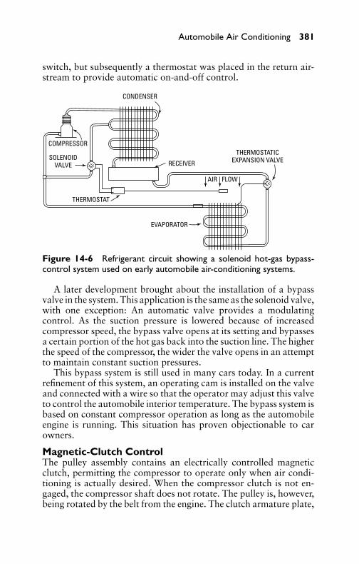
P1: GDZ/FFX P2: GDZ/FFX QC: GDZ/FFX T1: GDZ
GB076-14 GB076-Miller-Sample July 15, 2004 5:12 Char Count= 0
Automobile Air Conditioning 381
switch, but subsequently a thermostat was placed in the return air-stream to provide automatic on-and-off control.
CONDENSER
COMPRESSOR
SOLENOIDVALVE RECEIVER
THERMOSTATICEXPANSION VALVE
AIR FLOW
THERMOSTAT
EVAPORATOR
Figure 14-6 Refrigerant circuit showing a solenoid hot-gas bypass-control system used on early automobile air-conditioning systems.
A later development brought about the installation of a bypassvalve in the system. This application is the same as the solenoid valve,with one exception: An automatic valve provides a modulatingcontrol. As the suction pressure is lowered because of increasedcompressor speed, the bypass valve opens at its setting and bypassesa certain portion of the hot gas back into the suction line. The higherthe speed of the compressor, the wider the valve opens in an attemptto maintain constant suction pressures.
This bypass system is still used in many cars today. In a currentrefinement of this system, an operating cam is installed on the valveand connected with a wire so that the operator may adjust this valveto control the automobile interior temperature. The bypass system isbased on constant compressor operation as long as the automobileengine is running. This situation has proven objectionable to carowners.
Magnetic-Clutch ControlThe pulley assembly contains an electrically controlled magneticclutch, permitting the compressor to operate only when air condi-tioning is actually desired. When the compressor clutch is not en-gaged, the compressor shaft does not rotate. The pulley is, however,being rotated by the belt from the engine. The clutch armature plate,
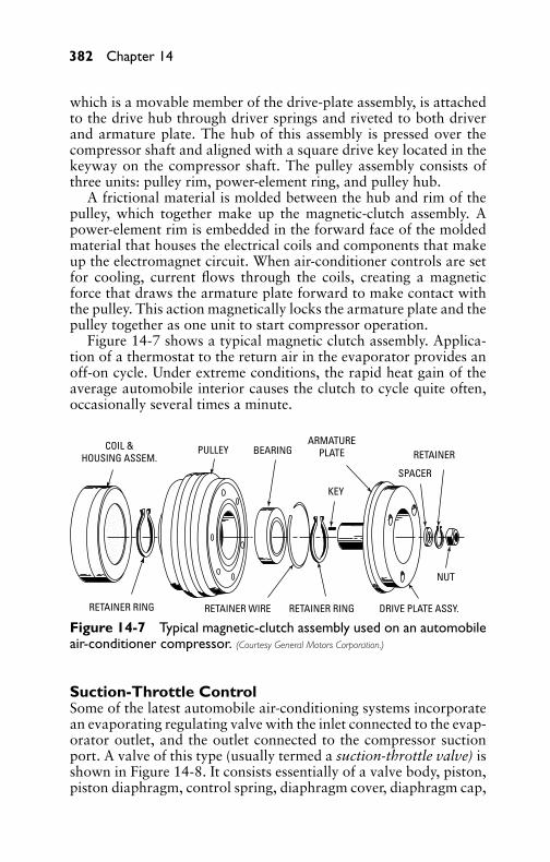
P1: GDZ/FFX P2: GDZ/FFX QC: GDZ/FFX T1: GDZ
GB076-14 GB076-Miller-Sample July 15, 2004 5:12 Char Count= 0
382 Chapter 14
which is a movable member of the drive-plate assembly, is attachedto the drive hub through driver springs and riveted to both driverand armature plate. The hub of this assembly is pressed over thecompressor shaft and aligned with a square drive key located in thekeyway on the compressor shaft. The pulley assembly consists ofthree units: pulley rim, power-element ring, and pulley hub.
A frictional material is molded between the hub and rim of thepulley, which together make up the magnetic-clutch assembly. Apower-element rim is embedded in the forward face of the moldedmaterial that houses the electrical coils and components that makeup the electromagnet circuit. When air-conditioner controls are setfor cooling, current flows through the coils, creating a magneticforce that draws the armature plate forward to make contact withthe pulley. This action magnetically locks the armature plate and thepulley together as one unit to start compressor operation.
Figure 14-7 shows a typical magnetic clutch assembly. Applica-tion of a thermostat to the return air in the evaporator provides anoff-on cycle. Under extreme conditions, the rapid heat gain of theaverage automobile interior causes the clutch to cycle quite often,occasionally several times a minute.
COIL &HOUSING ASSEM.
PULLEY BEARING
RETAINER RING RETAINER WIRE RETAINER RING
ARMATUREPLATE
KEY
RETAINER
SPACER
NUT
DRIVE PLATE ASSY.
Figure 14-7 Typical magnetic-clutch assembly used on an automobileair-conditioner compressor. (Courtesy General Motors Corporation.)
Suction-Throttle ControlSome of the latest automobile air-conditioning systems incorporatean evaporating regulating valve with the inlet connected to the evap-orator outlet, and the outlet connected to the compressor suctionport. A valve of this type (usually termed a suction-throttle valve) isshown in Figure 14-8. It consists essentially of a valve body, piston,piston diaphragm, control spring, diaphragm cover, diaphragm cap,
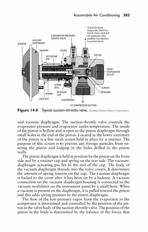
P1: GDZ/FFX P2: GDZ/FFX QC: GDZ/FFX T1: GDZ
GB076-14 GB076-Miller-Sample July 15, 2004 5:12 Char Count= 0
Automobile Air Conditioning 383
EVAPORATOR PRESSURESERVICE VALVE
VACUUMDIAPHRAGM
DIAPHRAGM
BUMPER
WASHER
ACTUATINGPIN
COVER
PISTON
FROMEVAPORATOROUTLET
SCREEN
RETAINERRETAINERCUP
LOCK NUT
SPRING
O-RINGSEAL
TO COMPRESSOR SUCTION
To junction block(evaporator bleed line,and its check valve andthe expansion valveequalizer line attachedto junction block)
Figure 14-8 Typical suction-throttle valve. (Courtesy General Motors Corporation.)
and vacuum diaphragm. The suction-throttle valve controls theevaporator pressure and evaporator outlet temperature. The insideof the piston is hollow and is open to the piston diaphragm throughsmall holes in the end of the piston. Located in the lower extremityof the piston is a fine mesh screen held in place by a retainer. Thepurpose of this screen is to prevent any foreign particles from en-tering the piston and lodging in the holes drilled in the pistonwalls.
The piston diaphragm is held in position by the piston on the frontside and by a retainer cup and spring on the rear side. The vacuum-diaphragm actuating pin fits in the end of the cup. The body ofthe vacuum diaphragm threads into the valve covers. It determinesthe amount of spring tension on the cup. The vacuum diaphragmis locked to the cover after it has been set by a locknut. A vacuumconnection on the vacuum diaphragm housing is connected to thevacuum modulator on the instrument panel by a small hose. Whena vacuum is present on the diaphragm, it is pulled toward the pistonand this adds spring pressure to the piston diaphragm.
The flow of the low-pressure vapor from the evaporator to thecompressor is determined and controlled by the position of the pis-ton in the valve body of the suction-throttle valve. The position of thepiston in the body is determined by the balance of the forces that

P1: GDZ/FFX P2: GDZ/FFX QC: GDZ/FFX T1: GDZ
GB076-14 GB076-Miller-Sample July 15, 2004 5:12 Char Count= 0
384 Chapter 14
are applied to the piston diaphragm. These forces consist of therefrigerant-vapor pressure returning from the evaporator, on oneside, and the spring tension plus the force of the actuating pin ifvacuum is present at the vacuum diaphragm, on the other side.Movement of the piston permits vapor to pass by scallops in thepiston skirt and then on to the compressor inlet.
During the time that maximum cooling is being produced, thesuction throttle-valve vacuum diaphragm does not have engine vac-uum applied to it. The full flow of low-pressure refrigerant vapor isbeing returned to the compressor to permit it to exert its full capac-ity on the evaporator and produce maximum cooling. Under mostall operating conditions, the suction-throttle-valve inlet and outletpressures will not be the same because there will be some throttlingto prevent evaporator icing.
When the operator wants to raise the temperature within thecar, the controls are changed to apply engine vacuum to the vacuumdiaphragm. This checks (or throttles) the flow of low-pressure vaporreturning to the compressor, resulting in a higher pressure to bemaintained in the evaporator assembly. The suction-throttle-valve-outlet pressure will also increase, but the differential between inletand outlet will be much greater than when the suction-throttle valveis at maximum cooling.
Air DistributionThe air is introduced in the car by various outlets, depending uponthe various types and models. The air-conditioner distribution sys-tem also varies, but is entirely separate from the car-heater distri-bution system. The air-conditioner distribution ducts are usuallylocated forward of the car-heater ducts, with one end positionedagainst the evaporator housing.
Air-Conditioner Control SystemThe operator controls the unit through switches located on the in-strument panel or on the evaporator case, depending upon the instal-lation procedure. (Follow the manufacturer’s instructions for properoperation.)
Service and MaintenanceSince automobile air conditioners do not differ in any importantrespect from home air conditioners insofar as the refrigeration cy-cle is concerned, such common procedures as charging, leak detec-tion, compressor testing, and other standard refrigeration serviceoperations will not be discussed in this chapter. Only servicing and
P1: GDZ/FFX P2: GDZ/FFX QC: GDZ/FFX T1: GDZ
GB076-14 GB076-Miller-Sample July 15, 2004 5:12 Char Count= 0
Automobile Air Conditioning 385
troubleshooting problems peculiar to automobile air conditioningwill be treated.
Insufficient or No CoolingIn a system incorporating a magnetic clutch and thermostatic switch,the first check is to make certain that the compressor is running. Theelectrical system should also be checked. The condition and tensionof the belt should be checked. In fact, correct tension on the belt isone of the most important service checks to be made. The tremen-dous load and high speed of these belts mean they must be kept verytight. Deflection of the belt between pulleys should not be more than1/4 inch. If a belt is replaced, this deflection should be checked afterabout a half-hour running period, and tightened again if necessary.
Air Output Not NormalWhen it has been determined that the compressor is operating prop-erly, blowers should be checked to make certain they are deliveringair. The blower control should be set at high. The temperature-control level (if there is one) should be set at maximum cooling.Insufficient discharge of air indicates an obstruction in the evapora-tor or electrical problems with the blower motor.
Air Output NormalIf actual air delivery at the discharge grill is about normal (around300 ft3/min), the next check is the position of the bypass dampers. Itis a well-known fact that the condensation of the refrigerant dependsupon air passing over the condenser as the automobile travels on theroad. To simulate this condition in the shop, a large fan should beplaced in front of the car. Head-pressure readings will vary some-what with ambient air temperatures. A fast idle (about 1500 rpm)and an ambient temperature of 75◦F should indicate head pressuresfrom 100 psig to 130 psig. For every 10◦F increase in the ambient-air temperature, an increase of about 20 psig will occur. Extremeambient temperatures (such as 110◦F or higher) may send the pres-sure as high as 300 psig. Extreme head pressure could indicate thepresence of dirt, air, or debris in the system.
Complete removal of air from the refrigerating system is essentialfor two reasons:� To prevent excessive head pressures when air volume over the
condenser is low.� To prevent decomposition of the oil, which is accelerated by
the normally higher operating temperatures encountered inthese systems.

P1: GDZ/FFX P2: GDZ/FFX QC: GDZ/FFX T1: GDZ
GB076-14 GB076-Miller-Sample July 15, 2004 5:12 Char Count= 0
386 Chapter 14
Sometimes an inexperienced person services the air-conditioningsystem and overcharges it, causing a high head pressure.
Checking Suction PressuresSuction pressures normally run about 16 psig to 25 psig at 75◦F.Any wide variation from these pressures indicates the usual serviceproblems resulting from this condition. Abnormally high suctionpressures indicate wide-open expansion valves, a loose feeler bulb,or leaky compressor valves. Valve plates usually can be replaced onthese compressors. The normal refrigeration procedures for check-ing compressor operation and maintenance are recommended.
Checking Control SystemsSystems equipped with the evaporator-regulator bypass-valve typeof controls or the expansion valve should present no difficult prob-lems to qualified service technician. Special features of these valvesmay dictate variations from normal refrigeration service practice.
Air DistributionIf an air-conditioning distribution system is not functioning prop-erly, first check the vacuum-hose connections, control cable, andvacuum-switch adjustments. If the controls and cables operate prop-erly, check for vacuum at valve diaphragms, proper functioning ofvacuum switches, and correct position of air valves. If the airflowchanges or shuts off when the car is accelerating, check for a faultyvalve at the intake manifold. If there is no vacuum to the suction-throttle valve when the cool switch is on, then check for a discon-nected vacuum hose at the vacuum modulator.
Defective CompressorCompressor malfunctioning will appear in one of four ways: noise,seizure, leakage, or low discharge pressures. Resonant compressornoises are no cause for excessive alarm, but irregular noises or rat-tles are likely to indicate broken parts. Seizure will be indicatedby the failure of the compressor to operate if the clutch is in goodoperating condition and there is no break in the electrical system.Figure 14-9 shows a wiring diagram of a typical automobile air con-ditioner. Continued operation of a partially seized compressor willresult in damage to the clutch. To check for seizure, de-energize theclutch and attempt to rotate the compressor by using a wrench onthe compressor shaft. If the shaft will not turn, the compressor isseized.
Leakage of compressor refrigerant may be detected through rou-tine leak detection. Low discharge pressures may also be caused by
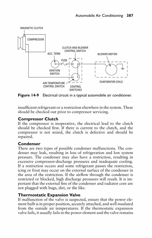
P1: GDZ/FFX P2: GDZ/FFX QC: GDZ/FFX T1: GDZ
GB076-14 GB076-Miller-Sample July 15, 2004 5:12 Char Count= 0
Automobile Air Conditioning 387
MAGNETIC CLUTCH
CLUTCH AND BLOWERCONTROL SWITCH
BLOWER MOTOR
EVAPORATOR COILS
CONTROLSWITCHES
AIR TEMPERATURECONTROL SWITCH
IGNITIONSWITCH
COMPRESSOR
ACC. TERM
FUSE
Figure 14-9 Electrical circuit in a typical automobile air conditioner.
insufficient refrigerant or a restriction elsewhere in the system. Theseshould be checked out prior to compressor servicing.
Compressor ClutchIf the compressor is inoperative, the electrical lead to the clutchshould be checked first. If there is current to the clutch, and thecompressor is not seized, the clutch is defective and should berepaired.
CondenserThere are two types of possible condenser malfunctions. The con-denser may leak, resulting in loss of refrigeration and low systempressure. The condenser may also have a restriction, resulting inexcessive compressor-discharge pressures and inadequate cooling.If a restriction occurs and some refrigerant passes the restriction,icing or frost may occur on the external surface of the condenser inthe area of the restriction. If the airflow through the condenser isrestricted or blocked, high discharge pressures will result. It is im-portant that the external fins of the condenser and radiator core arenot plugged with bugs, dirt, or the like.
Thermostatic Expansion ValveIf malfunction of the valve is suspected, ensure that the power ele-ment bulb is in proper position, securely attached, and well insulatedfrom the outside air temperatures. If the thermostatic expansionvalve fails, it usually fails in the power element and the valve remains

P1: GDZ/FFX P2: GDZ/FFX QC: GDZ/FFX T1: GDZ
GB076-14 GB076-Miller-Sample July 15, 2004 5:12 Char Count= 0
388 Chapter 14
closed. This will be indicated by low high-side or discharge pressure.The inlet screen could be plugged. The screen can be cleaned withliquid refrigerant.
EvaporatorDirt or other foreign matter on the core surface or in the evaporatorhousing will restrict the airflow. A cracked or broken housing canresult in leakage of cold air, as well as insufficient air or warm airbeing delivered to the passenger compartment.
Refrigerant LinesRestrictions in the refrigerant lines may be indicated as follows:
� High-pressure liquid line (low head pressure, no cooling).� Suction line (low suction pressure, low head pressure, little or
no cooling).� Discharge line (compressor blow off).� Receiver-drier (Leakage of refrigerant indicates a defective
unit. This cannot easily be checked, but if the system has beenexposed to outside air for a considerable length of time, theunit should be replaced).
Restrictions in the receiver-drier can also cause system malfunc-tion. If the inlet tube is blocked, it is likely to result in high headpressure. If the outlet tube is blocked, head pressure is likely to below and there will be little or no cooling.
Suction-Throttle ValveIf the suction-throttle valve is defective, it may cause evaporatorpressure to be too high (air-outlet temperature too warm), or itcould cause the evaporator pressure to be too low (air-outlet tem-perature too cold, which may cause icing of the evaporator core).If the vacuum diaphragm of the suction-throttle valve is defective,there would be no means to change (increase) the air-outlet tem-perature. Refrigerant leakage of the suction-throttle valve may bedetected through routine leak detection.
Before servicing the suction-throttle valve, it should be deter-mined that it is actually the cause of the complaint. If evaporatorpressure remains too high when checking and adjusting the suction-throttle valve, the low-pressure gage line should be attached to thevalve located on the compressor-suction line. If the compressor-suction pressure is also too high, the compressor or possibly thethermostatic expansion valve may be the cause of the trouble.
P1: GDZ/FFX P2: GDZ/FFX QC: GDZ/FFX T1: GDZ
GB076-14 GB076-Miller-Sample July 15, 2004 5:12 Char Count= 0
Automobile Air Conditioning 389
Use of Receiver Sight Glass for DiagnosisA clear sight glass will indicate a properly charged refrigerationsystem. The occurrence of slow moving gas bubbles or a brokencolumn of refrigerant for momentary periods during normal opera-tion should not be considered an indication of refrigerant shortageif the sight glass is generally clear and performance is satisfactory.The tendency of the sight glass to indicate refrigerant shortage whenthe system is under light load should be considered.
If the sight glass consistently shows foaming or a broken liquidcolumn, it should be observed after partially blocking the air tothe condenser. If, under this condition, the sight glass clears and theperformance is otherwise satisfactory, the charge shall be consideredadequate. In all instances where the indication of refrigerant short-age continues, additional refrigerant should be added in 1/4-poundincrements until the sight glass is clear. An additional charge of 1/2pound should be added as a reserve. In no case should the systembe overcharged.
Installation ProcedureTwo installation methods for automobile air conditioning are fac-tory installation and universal-type installation. Factory-installedair conditioners are furnished with the automobiles, usually withinstructions for proper maintenance and operation. In such instal-lations, several methods are used on evaporator assemblies. Manysuch installations combine the heating system with the cooling sys-tem, as shown in Figure 14-10, with the evaporator coil and heatercore located in the same enclosure. One significant service prob-lem that should be pointed out here is the function of the bypassdampers.
A common complaint of no cooling is corrected by proper ad-justment of the bypass dampers, which, in many installations, arecontrolled by cables that operate dampers to furnish outside or re-circulated air. These control cables are connected to a control panelin such a way that the combined functions are accomplished or con-trolled through a single lever. Figure 14-11 shows a more recentrefinement in damper controls. Here, vacuum actuators are usedwith pushbutton control. Installations of this sort mean that servicetechnicians must thoroughly acquaint themselves with the basic op-erating principle governing this type of control. These controls aresimilar in many respects to the controls used in pneumatic-controlledair-conditioning systems.
The evaporator housings resemble the old-fashioned automobileheaters that were suspended under the dash. This construction,

P1: GDZ/FFX P2: GDZ/FFX QC: GDZ/FFX T1: GDZ
GB076-14 GB076-Miller-Sample July 15, 2004 5:12 Char Count= 0
390 Chapter 14
EVAPORATOR(COOLING COILS)
BLEND-AIRVALVE
BLOWER
FROM GRILLOPENING
AIR OUTLETSINTO PASSENGERCOMPARTMENT
HEATER CORE
T-VALVE
LOWERLEVELAT OFF
POSITION
LOWER LEVELAT HEAT POSITION
OPENING FROMPASSENGER
COMPARTMENT
BLOWER INLETAIR VALVE
Figure 14-10 Schematic diagram showing heating- and cooling-coilarrangements.
DISTRIBUTIONDUCT
TEMPERATURECONTROL LEVER
PUSHBUTTON
CONTROL
SPOTCOOLER
EVAPORATOR
FRESH AIRINLET DOOR RECIRCULATING
DOOR
BYPASS DOOR
VACUUMACTUATOR
VACUUMACTUATOR
VACUUM ACTUATORS
TEMPERATURECONTROL VALVE
HEATERCORE
BLOWER
DAMPER
TEMPERATURE CONTROL CABLE TOTEMPERATURE CONTROL VALVE
FLOOR LEVEL OUTLETSCABLE KNOB
Figure 14-11 Typical damper-control assembly showing vacuumactuators with pushbutton controls.
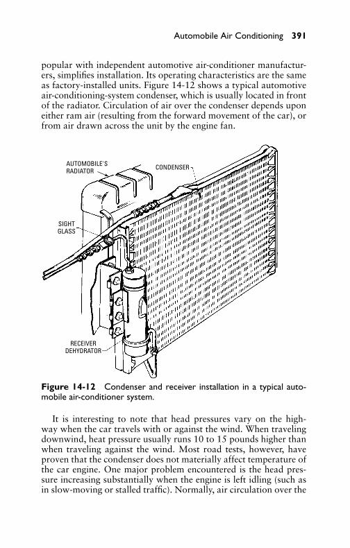
P1: GDZ/FFX P2: GDZ/FFX QC: GDZ/FFX T1: GDZ
GB076-14 GB076-Miller-Sample July 15, 2004 5:12 Char Count= 0
Automobile Air Conditioning 391
popular with independent automotive air-conditioner manufactur-ers, simplifies installation. Its operating characteristics are the sameas factory-installed units. Figure 14-12 shows a typical automotiveair-conditioning-system condenser, which is usually located in frontof the radiator. Circulation of air over the condenser depends uponeither ram air (resulting from the forward movement of the car), orfrom air drawn across the unit by the engine fan.
CONDENSERAUTOMOBILE'SRADIATOR
SIGHTGLASS
RECEIVERDEHYDRATOR
Figure 14-12 Condenser and receiver installation in a typical auto-mobile air-conditioner system.
It is interesting to note that head pressures vary on the high-way when the car travels with or against the wind. When travelingdownwind, heat pressure usually runs 10 to 15 pounds higher thanwhen traveling against the wind. Most road tests, however, haveproven that the condenser does not materially affect temperature ofthe car engine. One major problem encountered is the head pres-sure increasing substantially when the engine is left idling (such asin slow-moving or stalled traffic). Normally, air circulation over the

P1: GDZ/FFX P2: GDZ/FFX QC: GDZ/FFX T1: GDZ
GB076-14 GB076-Miller-Sample July 15, 2004 5:12 Char Count= 0
Tabl
e14
-1A
uto
mo
bile
Air
-Co
ndit
ioni
ngT
roub
lesh
oo
ting
Gui
de
Sym
pto
mP
ossi
ble
Cau
seP
ossi
ble
Rem
edy
Insu
ffici
ent
cool
ing.
Low
airfl
ow.
Che
ckbl
ower
oper
atio
n.C
heck
for
obst
ruct
ion
inai
r-di
stri
buti
onsy
stem
.Che
ckfo
rcl
ogge
dev
apor
ator
.If
iced
,de-
ice
core
and
chec
kad
just
men
tan
dop
erat
ion
ofsu
ctio
n-th
rott
leva
lve.
Def
ecti
vehe
ater
-te
mpe
ratu
reco
ntro
lval
ve.
Che
ckop
erat
ion
ofva
lve.
Adj
ust
orre
plac
eas
nece
ssar
y.
Hea
ter
cont
rols
orve
ntila
tor
cont
roln
otin
the
off
posi
tion
.A
dvis
eop
erat
orof
corr
ect
oper
atio
nof
cont
rols
.
Com
pres
sor
disc
harg
epr
essu
reto
ohi
gh.
Eng
ine
over
heat
ed.
Ove
rcha
rge
ofre
frig
eran
tor
air
insy
stem
.
Che
ckfo
rpo
ssib
leca
use.
Syst
ems
wit
hex
cess
disc
harg
epr
essu
res
shou
ldbe
slow
lyde
pres
suri
zed.
Ifdi
scha
rge
pres
sure
drop
sra
pidl
y,it
indi
cate
sai
r(w
ith
poss
ibili
tyof
moi
stur
e)in
the
syst
em.W
hen
pres
sure
leve
lsdr
opbu
tar
est
illin
exce
ssof
spec
ifica
tion
s,sl
owly
blee
dsy
stem
unti
lbub
bles
appe
arin
the
sigh
tgl
ass
and
stop
.Add
refr
iger
ant
unti
lbub
bles
clea
r.T
hen
add
1 /2
poun
dof
refr
iger
ant.
Rec
heck
oper
atio
nal
pres
sure
s.If
syst
empr
essu
res
still
rem
ain
abov
esp
ecifi
cati
ons
and
the
evap
orat
orpr
essu
reis
slig
htly
abov
eno
rmal
,the
na
rest
rict
ion
exis
tsin
the
high
-pre
ssur
esi
deof
the
syst
em.
Ifdi
scha
rge
pres
sure
drop
ssl
owly
,it
indi
cate
sex
cess
ive
refr
iger
ant.
Ifpr
essu
res
drop
tosp
ecifi
cati
ons
and
sigh
tgl
ass
rem
ains
clea
r,st
opde
pres
suri
zing
and
rech
eck
oper
atio
nal
pres
sure
s.If
pres
sure
sar
esa
tisf
acto
ry,d
epre
ssur
ize
unti
lbub
bles
appe
arin
the
sigh
tgl
ass,
stop
depr
essu
rizi
ng,a
ndth
enad
d1 /
2
poun
dre
frig
eran
t.R
eche
ckop
erat
iona
lpre
ssur
es.
392

P1: GDZ/FFX P2: GDZ/FFX QC: GDZ/FFX T1: GDZ
GB076-14 GB076-Miller-Sample July 15, 2004 5:12 Char Count= 0
Tabl
e14
-1(c
onti
nued
)
Ifdi
scha
rge
pres
sure
rem
ains
high
afte
rde
pres
suri
zing
the
syst
em,
cont
inue
depr
essu
rizi
ngun
tilb
ubbl
esap
pear
inth
esi
ght
glas
s.If
evap
orat
orpr
essu
res
also
rem
ain
high
,the
reis
apo
ssib
ility
ofa
rest
rict
ion
inth
ehi
gh-p
ress
ure
side
ofth
ere
frig
erat
ion
syst
em,o
rth
esu
ctio
nth
rott
leva
lve
may
requ
ire
adju
stm
ent.
Res
tric
tion
inco
nden
ser
orre
ceiv
erliq
uid
indi
cato
r.R
emov
epa
rts,
insp
ect,
and
clea
nor
repl
ace.
Con
dens
erai
rflow
bloc
ked.
Cle
anco
nden
ser
and
radi
ator
core
surf
aces
asw
ella
sth
esp
ace
betw
een
the
cond
ense
ran
dra
diat
or.
Eva
pora
tor
pres
sure
too
high
.Se
e“E
vapo
rato
rpr
essu
reto
ohi
gh”
(bel
ow).
Com
pres
sor
disc
harg
epr
essu
reto
olo
w.
Insu
ffici
ent
refr
iger
ant.
Che
ckfo
rpr
esen
ceof
bubb
les
orfo
amin
liqui
din
dica
tor.
Ifbu
bble
sor
foam
are
note
d(a
fter
5m
inut
esof
oper
atio
n),c
heck
syst
emfo
rle
aks.
Ifno
leak
sar
efo
und,
refr
iger
ant
shou
ldbe
adde
dun
tils
ight
glas
scl
ears
.The
nad
dan
addi
tion
al1 /
2po
und.
Low
suct
ion
pres
sure
.Se
e“E
vapo
rato
rpr
essu
reto
olo
w”
(bel
ow).
Def
ecti
veco
mpr
esso
ran
d/or
brok
enco
mpr
esso
rre
edva
lves
.R
epai
rco
mpr
esso
r.
Eva
pora
tor
pres
sure
too
high
.T
herm
osta
tic
expa
nsio
nva
lve
capi
llary
-tub
ebu
lbno
tti
ght
toev
apor
ator
outl
ettu
be.
Che
ckfo
rti
ghtn
ess.
(con
tinu
ed)
393

P1: GDZ/FFX P2: GDZ/FFX QC: GDZ/FFX T1: GDZ
GB076-14 GB076-Miller-Sample July 15, 2004 5:12 Char Count= 0
Tabl
e14
-1(c
onti
nued
)
Sym
pto
mP
ossi
ble
Cau
seP
ossi
ble
Rem
edy
The
rmos
tati
cex
pans
ion
valv
eim
prop
erly
adju
sted
orin
oper
ativ
e.
Rep
lace
valv
e.
Suct
ion-
thro
ttle
valv
ead
just
edim
prop
erly
orde
fect
ive.
Che
ckop
erat
ion
ofsu
ctio
n-th
rott
leva
lve.
Rep
air
valv
eif
nece
ssar
y.V
acuu
mm
odul
ator
defe
ctiv
e.T
here
shou
ldbe
nova
cuum
toth
esu
ctio
n-th
rott
leva
lve
whe
nco
olle
velo
nin
stru
men
tpa
neli
sat
max
imum
onpo
siti
on.
Rep
lace
vacu
umm
odul
ator
ifde
fect
ive.
Not
e:If
com
pres
sor-
suct
ion
line
from
suct
ion-
thro
ttle
valv
eis
muc
hco
lder
than
suct
ion
thro
ttle
-val
vein
let
line
from
evap
orat
or,t
his
indi
cate
sth
atsu
ctio
n-th
rott
leva
lve-
outl
etpr
essu
reis
muc
hlo
wer
than
inle
tpr
essu
re,a
ndth
esu
ctio
n-th
rott
leva
lve
may
bede
fect
ive.
Eva
pora
tor
pres
sure
too
low
.T
herm
osta
tic
expa
nsio
nva
lve
capi
llary
tube
brok
en,i
nlet
scre
enpl
ugge
d,or
valv
eot
herw
ise
faile
d.
Rep
lace
valv
eor
clea
nin
let
scre
enof
valv
e.
Res
tric
tion
insy
stem
tube
sor
hose
s.R
epla
ceki
nked
tube
orre
stri
cted
hose
.
Suct
ion-
thro
ttle
valv
ead
just
edim
prop
erly
orde
fect
ive.
Che
ckop
erat
ion
ofsu
ctio
nth
rott
leva
lve.
Rep
air
ifne
cess
ary.
394
P1: GDZ/FFX P2: GDZ/FFX QC: GDZ/FFX T1: GDZ
GB076-14 GB076-Miller-Sample July 15, 2004 5:12 Char Count= 0
Automobile Air Conditioning 395
condenser is supplied by the forward movement of the car. At highspeeds, the ram effect of this air does an adequate job of cooling thecondenser. At more moderate speeds, the fan draws sufficient airover the condenser to keep head pressures normal, but when the caris stalled or is traveling very slowly, air volume is not sufficient tokeep head pressures within operating limits. Some systems providea fast-idling control, which increases the engine speed sufficiently tosupply air over the condenser.
Location of the condenser in front of the car contributes to accu-mulation of dirt and debris on the finned surface. Recently developedservice tools for effectively cleaning finned surfaces are available.Also shown in Figure 14-12 is the system receiver. An innovationis encountered here through the frequent practice of placing a driercore within the receiver, thus resulting in a combination receiver-drier unit. This construction may pose a question to some servicetechnicians: With the drier located within the receiver, how can thiscomponent be replaced?
Since present automobile air-conditioning systems make no pro-vision to pump down the unit, there is no need for a liquid-line valve.The only valves available are the suction and discharge service valvesat the compressor. This simply means that if any service operationis required away from the compressor itself, the refrigerant must beremoved from the system. The drier cartridge inside the receiver alsousually provides a filter. Many times this is the only filter or screenin the system since the expansion valve is not always equipped witha screen. This fact makes such a filter vital to system operation.
Troubleshooting GuideThe troubleshooting guide shown in Table 14-1 lists the most com-mon operating faults along with possible causes and suggestedchecks and correction for each. This guide is intended to providea quick reference to the cause and correction of a specific fault.
SummaryThe automobile air-conditioning system is no different from anyother type of air-conditioning system. The major components arethe same.
The two temperature controls most frequently used on automo-bile air-conditioning systems are the magnetic clutch (operated byelectricity) and the refrigerant-flow control.
Today all automobile air-conditioner compressors are driven bya belt from the engine crankshaft. The compressor speed varies withthe speed of the automobile engine.

P1: GDZ/FFX P2: GDZ/FFX QC: GDZ/FFX T1: GDZ
GB076-14 GB076-Miller-Sample July 15, 2004 5:12 Char Count= 0
396 Chapter 14
Air-conditioning condensers are similar to the ordinary automo-bile radiator, but are designed to withstand much higher pressures.They are normally mounted in front of the car radiator.
The function of the thermostatic expansion valve is to automat-ically regulate the flow of liquid refrigerant into the evaporatorin accordance with the requirements of the evaporator. The tem-perature of the air passing over the evaporator core determinesthe amount of refrigerant that will enter and pass through theevaporator.
When the compressor clutch is not engaged, the compressor shaftwill not rotate. However, the pulley is being rotated by the belt fromthe crankshaft pulley. The clutch is engaged when the electric sole-noid of the magnetic clutch is energized. This causes the mag-netic properties of the clutch assembly to attract the pulley sectionand cause it to engage the section that connects to the compressorshaft.
Some recent automobile air-conditioning systems incorporatean evaporating regulating valve with the inlet connected to theevaporator outlet, and the outlet connected to the compres-sor suction port. This type of valve is called a suction-throttlevalve.
Review Questions1. How does the automobile air-conditioning system differ
from the air conditioner sticking out of the living-roomwindow?
2. How does the automobile air-conditioning system operate?3. Why are automobile compressors different from those used in
the home air-conditioning unit?4. Where is the condenser located on an automobile to take ad-
vantage of airflow?5. What is the difference between the solenoid hot-gas bypass-
control system and the older solenoid-control system?6. Explain the difference between the magnetic clutch and the
suction-throttle control.7. What does abnormally high suction pressure indicate on an
automobile air-conditioning system?8. What are four ways that the compressor system indicates mal-
functioning?

P1: GDZ/FFX P2: GDZ/FFX QC: GDZ/FFX T1: GDZ
GB076-14 GB076-Miller-Sample July 15, 2004 5:12 Char Count= 0
Automobile Air Conditioning 397
9. What are the two possible condenser malfunctions?10. What trouble does a defective suction valve cause to an air-
conditioning system?11. What are the two methods of acquiring automobile air condi-
tioning?12. Why is the receiver filter so important in an automobile air-
conditioning system?

P1: GDZ/FFX P2: GDZ/FFX QC: GDZ/FFX T1: GDZ
GB076-14 GB076-Miller-Sample July 15, 2004 5:12 Char Count= 0
398

P1: GDZ/FFX P2: GDZ/FFX QC: GDZ/FFX T1: GDZ
GB076-15 GB076-Miller-Sample July 15, 2004 18:31 Char Count= 0
Chapter 15Motors and Motor ControlsThe electric motor is the prime mover in most air-conditioningapplications. The type of motor used for a particular condensingunit depends on the following essential factors:
� Power source (whether direct or alternating current)� Voltage and frequency of current� Voltage regulation� Phases (whether single- or three-phase)
In selecting a motor for a particular application, the first consid-eration should be the available power source. Since 60-Hertz alter-nating current (AC) is available in most locations throughout thecountry, a satisfactory performance usually can be obtained by em-ploying AC motors with accompanying controls. In locations whereonly direct current (DC) is available, shunt and compound-woundmotors with suitable controllers may be employed. Series-woundDC motors, however, are not suitable for compressor drive becauseof their special speed characteristics.
Motor VoltageAs noted previously, the power source in practically all locationsis alternating current. Isolated plants usually generate direct cur-rent for small loads in confined areas. The conventional three-phaseAC system is normally used for operation of large motors, whereassingle-phase AC is used for motors having fractional-horsepowerratings. Standard conditions of voltage and frequency are the valueslisted on the motor nameplate.
Alternating current motors may be divided into a couple of classi-fications (depending on power supply and winding types): polyphaseand single-phase. Where polyphase power is available, it is usu-ally more economical to use polyphase motors instead of single-phase motors because of their higher efficiency and higher powerfactor. Single-phase motors are universally employed in fractional-horsepower sizes and in portable and central air-conditioning sys-tems for homes and small industrial plants.
Polyphase MotorsPolyphase motors are classified according to winding methods asfollows:
399
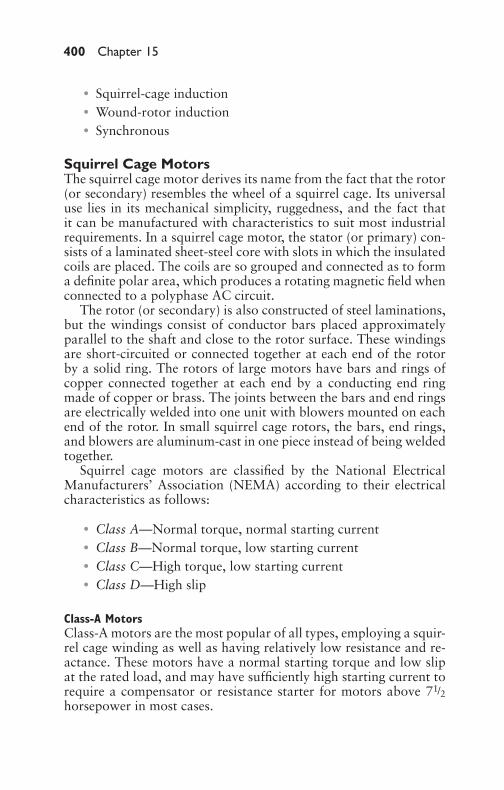
P1: GDZ/FFX P2: GDZ/FFX QC: GDZ/FFX T1: GDZ
GB076-15 GB076-Miller-Sample July 15, 2004 18:31 Char Count= 0
400 Chapter 15
� Squirrel-cage induction� Wound-rotor induction� Synchronous
Squirrel Cage MotorsThe squirrel cage motor derives its name from the fact that the rotor(or secondary) resembles the wheel of a squirrel cage. Its universaluse lies in its mechanical simplicity, ruggedness, and the fact thatit can be manufactured with characteristics to suit most industrialrequirements. In a squirrel cage motor, the stator (or primary) con-sists of a laminated sheet-steel core with slots in which the insulatedcoils are placed. The coils are so grouped and connected as to forma definite polar area, which produces a rotating magnetic field whenconnected to a polyphase AC circuit.
The rotor (or secondary) is also constructed of steel laminations,but the windings consist of conductor bars placed approximatelyparallel to the shaft and close to the rotor surface. These windingsare short-circuited or connected together at each end of the rotorby a solid ring. The rotors of large motors have bars and rings ofcopper connected together at each end by a conducting end ringmade of copper or brass. The joints between the bars and end ringsare electrically welded into one unit with blowers mounted on eachend of the rotor. In small squirrel cage rotors, the bars, end rings,and blowers are aluminum-cast in one piece instead of being weldedtogether.
Squirrel cage motors are classified by the National ElectricalManufacturers’ Association (NEMA) according to their electricalcharacteristics as follows:
� Class A—Normal torque, normal starting current� Class B—Normal torque, low starting current� Class C—High torque, low starting current� Class D—High slip
Class-A MotorsClass-A motors are the most popular of all types, employing a squir-rel cage winding as well as having relatively low resistance and re-actance. These motors have a normal starting torque and low slipat the rated load, and may have sufficiently high starting current torequire a compensator or resistance starter for motors above 71/2horsepower in most cases.
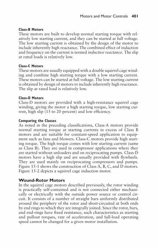
P1: GDZ/FFX P2: GDZ/FFX QC: GDZ/FFX T1: GDZ
GB076-15 GB076-Miller-Sample July 15, 2004 18:31 Char Count= 0
Motors and Motor Controls 401
Class-B MotorsThese motors are built to develop normal starting torque with rel-atively low starting current, and they can be started at full voltage.The low starting current is obtained by the design of the motor toinclude inherently high reactance. The combined effect of inductionand frequency on the current is termed inductive reactance. The slipat rated loads is relatively low.
Class-C MotorsThese motors are usually equipped with a double squirrel cage wind-ing and combine high starting torque with a low starting current.These motors can be started at full voltage. The low starting currentis obtained by design of motors to include inherently high reactance.The slip at rated load is relatively low.
Class-D MotorsClass-D motors are provided with a high-resistance squirrel cagewinding, giving the motor a high starting torque, low starting cur-rent, high slip (15 to 20 percent) and low efficiency.
Comparing the ClassesAs noted in the preceding classifications, Class-A motors providenormal starting torque at starting currents in excess of Class Bmotors and are suitable for constant-speed application to equip-ment such as fans and blowers. Class-C motors provide high start-ing torque. The high torque comes with low starting current (sameas Class B). They are used in compressor applications where theyare started without unloaders and on reciprocating pumps. Class-Dmotors have a high slip and are usually provided with flywheels.They are used mainly on reciprocating compressors and pumps.Figure 15-1 shows the construction of Class A, B, C, and D motors.Figure 15-2 depicts a squirrel cage induction motor.
Wound-Rotor MotorsIn the squirrel cage motors described previously, the rotor windingis practically self-contained and is not connected either mechani-cally or electrically with the outside power source or control cir-cuit. It consists of a number of straight bars uniformly distributedaround the periphery of the rotor and short-circuited at both endsby end rings to which they are integrally joined. Since the rotor, bars,and end-rings have fixed resistance, such characteristics as startingand pullout torques, rate of acceleration, and full-load operatingspeed cannot be changed for a given motor installation.

P1: GDZ/FFX P2: GDZ/FFX QC: GDZ/FFX T1: GDZ
GB076-15 GB076-Miller-Sample July 15, 2004 18:31 Char Count= 0
402 Chapter 15
LOW RESISTANCEWINDING
HIGH USEFULFLUX
LOW LEAKAGEFLUX
HIGH RESISTANCEWINDING
MEDIUM USEFULFLUX
HIGHLEAKAGE
FLUX
LOWLEAKAGE
FLUX
HIGH LEAKAGEFLUX
MEDIUM USEFULFLUX
HIGH USEFULFLUX
(A) Class A.
(B) Class B.
(C) Class C.
(D) Class D.
Figure 15-1 Squirrel cage rotor construction for Class A, B, C, andD motors, respectively.
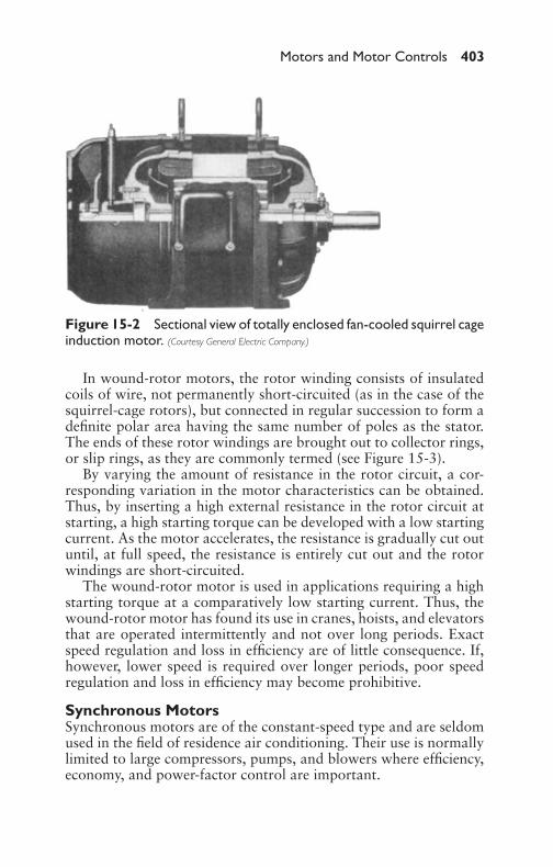
P1: GDZ/FFX P2: GDZ/FFX QC: GDZ/FFX T1: GDZ
GB076-15 GB076-Miller-Sample July 15, 2004 18:31 Char Count= 0
Motors and Motor Controls 403
Figure 15-2 Sectional view of totally enclosed fan-cooled squirrel cageinduction motor. (Courtesy General Electric Company.)
In wound-rotor motors, the rotor winding consists of insulatedcoils of wire, not permanently short-circuited (as in the case of thesquirrel-cage rotors), but connected in regular succession to form adefinite polar area having the same number of poles as the stator.The ends of these rotor windings are brought out to collector rings,or slip rings, as they are commonly termed (see Figure 15-3).
By varying the amount of resistance in the rotor circuit, a cor-responding variation in the motor characteristics can be obtained.Thus, by inserting a high external resistance in the rotor circuit atstarting, a high starting torque can be developed with a low startingcurrent. As the motor accelerates, the resistance is gradually cut outuntil, at full speed, the resistance is entirely cut out and the rotorwindings are short-circuited.
The wound-rotor motor is used in applications requiring a highstarting torque at a comparatively low starting current. Thus, thewound-rotor motor has found its use in cranes, hoists, and elevatorsthat are operated intermittently and not over long periods. Exactspeed regulation and loss in efficiency are of little consequence. If,however, lower speed is required over longer periods, poor speedregulation and loss in efficiency may become prohibitive.
Synchronous MotorsSynchronous motors are of the constant-speed type and are seldomused in the field of residence air conditioning. Their use is normallylimited to large compressors, pumps, and blowers where efficiency,economy, and power-factor control are important.
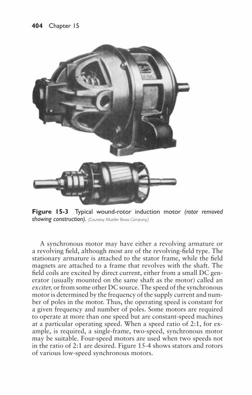
P1: GDZ/FFX P2: GDZ/FFX QC: GDZ/FFX T1: GDZ
GB076-15 GB076-Miller-Sample July 15, 2004 18:31 Char Count= 0
404 Chapter 15
Figure 15-3 Typical wound-rotor induction motor (rotor removedshowing construction). (Courtesy Mueller Brass Company.)
A synchronous motor may have either a revolving armature ora revolving field, although most are of the revolving-field type. Thestationary armature is attached to the stator frame, while the fieldmagnets are attached to a frame that revolves with the shaft. Thefield coils are excited by direct current, either from a small DC gen-erator (usually mounted on the same shaft as the motor) called anexciter, or from some other DC source. The speed of the synchronousmotor is determined by the frequency of the supply current and num-ber of poles in the motor. Thus, the operating speed is constant fora given frequency and number of poles. Some motors are requiredto operate at more than one speed but are constant-speed machinesat a particular operating speed. When a speed ratio of 2:1, for ex-ample, is required, a single-frame, two-speed, synchronous motormay be suitable. Four-speed motors are used when two speeds notin the ratio of 2:1 are desired. Figure 15-4 shows stators and rotorsof various low-speed synchronous motors.

P1: GDZ/FFX P2: GDZ/FFX QC: GDZ/FFX T1: GDZ
GB076-15 GB076-Miller-Sample July 15, 2004 18:31 Char Count= 0
Motors and Motor Controls 405
Figure 15-4 Stators and rotors of three low-speed synchronous mo-tors. (Courtesy Crocker-Wheeler Corporation.)
The single-frame, two-speed motor is usually of salient-pole con-struction, with the number of poles corresponding to the low speed.High speed is obtained by regrouping the poles to obtain two ad-jacent poles of the same polarity, followed by two poles of oppo-site polarity, which gives the effect of reducing the number of poleson the rotor by one-half for high-speed operation. Corresponding

P1: GDZ/FFX P2: GDZ/FFX QC: GDZ/FFX T1: GDZ
GB076-15 GB076-Miller-Sample July 15, 2004 18:31 Char Count= 0
406 Chapter 15
changes in the stator connections are also made. This switching isusually accomplished automatically by means of magnetic starting,or manually operated pole-changing equipment may be used.
Single-Phase MotorsSingle-phase induction motors are provided with auxiliary windingsor other devices for starting and are used on all types of home ap-pliances. They are also made for a great variety of domestic and in-dustrial applications in sizes up to about 5 horsepower. Single-phasemotors are classified according to their construction and method ofstarting as follows:
� Split-phase� Capacitor-start� Two-valve capacitor� Permanent split-capacitor� Repulsion induction� Repulsion-start induction
Split-Phase MotorsThe split-phase motor consists essentially of a squirrel cage rotor,two stator windings, a main winding, and an auxiliary or start wind-ing (see Figure 15-5). The main winding is connected across thesupply lines in the usual manner and has a low resistance and ahigh inductance. The start or auxiliary winding (which is physically
FRONT ENDPLATE STATOR
ROTOR
CENTRIFUGAL SWITCH
REAR ENDPLATE
Figure 15-5 Disassembled view of a typical single-phase inductionmotor.

P1: GDZ/FFX P2: GDZ/FFX QC: GDZ/FFX T1: GDZ
GB076-15 GB076-Miller-Sample July 15, 2004 18:31 Char Count= 0
Motors and Motor Controls 407
POTENTIALRELAY
STARTINGWINDING
MAINWINDING
S C R
LINE
Figure 15-6 Schematic di-agram that shows connec-tions of a typical split-phaseinduction motor with asso-ciated potential relay whosefunction is to disconnectstart windings when operat-ing speed has been reached.
displaced in the stator from the mainwinding) has a high resistance anda low inductance. This physical dis-placement, in addition to the electricalphase displacement produced by therelative electrical resistance values inthe two windings, produces a weak ro-tating field that is sufficient to providea low starting torque.
After the motor has acceleratedto 75 or 80 percent of its syn-chronous speed, a starting relay opensits contacts to disconnect the start-ing winding (Figures 15-6 and 15-7).The function of the starting relay isto prevent the motor from drawingexcessive current from the line andprotect the start winding from damagecaused by heating. The motor may be started in either direction byreversing either the main or the auxiliary winding. The split-phasemotor is most commonly used in sizes ranging from 1/30 to 1/2 horse-power for fans, business machines, automatic musical instruments,buffing machines, grinders, and numerous other applications.
Capacitor-Start MotorsThe capacitor-start motor is another form of a split-phase motor,but has a capacitor connected in series with the auxiliary winding.
STARTINGWINDING
MAINWINDING
CURRENTRELAY
S C R
LINE
Figure 15-7 Schematic di-agram of a typical split-phase induction motor witha current-type relay to dis-connect the start winding atapproximately 85 percent ofrated speed.
The auxiliary circuit is opened whenthe motor has attained a predeter-mined speed. The rotor is of the squir-rel cage type, as in other split-phasemotors. The main winding is con-nected directly across the line, whilethe auxiliary or starting winding isconnected through a capacitor, whichmay be connected into the circuitthrough a transformer with suitablydesigned windings. The two windingswill be approximately 90◦ apart elec-trically. Capacitor-start motors have acomparatively high starting torque ac-companied by a high power factor andare used in fractional-horsepower sizes

P1: GDZ/FFX P2: GDZ/FFX QC: GDZ/FFX T1: GDZ
GB076-15 GB076-Miller-Sample July 15, 2004 18:31 Char Count= 0
408 Chapter 15
POTENTIALRELAY
STARTINGCAPACITOR
STARTINGWINDING
MAINWINDING
S C R
LINE
Figure 15-8 Capacitor-start, split-phase inductionmotor with potential relay.
STARTINGCAPACITOR
STARTINGWINDING
MAINWINDING
CURRENTRELAY
S C R
LINE
Figure 15-9 Capacitor-start, split-phase inductionmotor with current-typerelay.
POTENTIALRELAY
STARTINGCAPACITOR
RUNNINGCAPACITOR
STARTINGWINDING
MAINWINDING
S C R
LINE
Figure 15-10 Two-valve,capacitor-start, split-phaseinduction motor with poten-tial relay.
for constant-speed drive on fans,blowers, and centrifugal pumps. Fig-ure 15-8 and Figure 15-9 showcapacitor-start, split-phase inductionmotors.
Two-Value Capacitor MotorsIn the two-value capacitor motor, themain winding is connected directlyto the power supply and the aux-iliary winding is permanently con-nected in series with a run capacitor(see Figure 15-10). The run capacitorprovides high efficiency at normalspeed. The start capacitor gives highstarting ability and is cut out of thecircuit by a centrifugal switch afterthe motor has attained a predeter-mined speed (usually about 80 percentof its running speed). These motorsdevelop a high starting torque in thefractional-horsepower sizes. They areused on compressors, reciprocatingpumps, and similar equipment thatmay start under heavy load.
Permanent Split-CapacitorMotorsIn the permanent split-capacitor mo-tor, the main winding is connected di-rectly to the power source and the aux-iliary winding is connected in serieswith a capacitor (see Figure 15-11).The capacitor and auxiliary windingremain in the circuit while the motor isin operation. There are several types ofcapacitor motors, differing from oneanother mainly in the number and ar-rangement of capacitors employed.
The running characteristics of thepermanent split-capacitor motor areextremely favorable, and the torqueis fixed by the amount of additional

P1: GDZ/FFX P2: GDZ/FFX QC: GDZ/FFX T1: GDZ
GB076-15 GB076-Miller-Sample July 15, 2004 18:31 Char Count= 0
Motors and Motor Controls 409
RUNNINGCAPACITOR
STARTINGWINDING
MAINWINDING
S C R
LINE
Figure 15-11 Typical per-manent split-capacitor in-duction motor.
capacitance added to the auxiliarywinding during the starting period. Itsoperation is similar to the capacitor-start motor, except that the capacitorremains in the circuit when running.The motor is ideally suitable for smallfan drives and other appliances whereonly a limited amount of startingtorque is required.
Repulsion Induction MotorsRepulsion induction motors are equipped with two rotor windings:a squirrel cage for running and a wound-rotor winding connectedto a commutator for starting. Both of those rotor windings functionduring the entire operation period of the motor. There are no auto-matic devices (such as the starting switch of the split-phase motor orthe short-circuiting device of the repulsion-start induction motor).
The cage winding is located in slots below those containing thecommutator winding. The slots containing the two windings mayor may not be connected by a narrow slot. Usually there is the samenumber of slots in the two windings. However, it is not essentialthat they be the same. At full-load speed (which is slightly belowsynchronism) the reactance of the cage winding is low and most ofthe mutual flux passes beneath the cage winding.
Both windings produce torque, and the output of the motor is thecombined output of the cage winding and the commutated wind-ing. The repulsion induction motor is especially suitable for house-hold refrigerators, water systems, garage air pumps, gasoline pumps,compressors, and similar applications.
Repulsion-Start Induction MotorsThe repulsion-start induction motor is similar to the repulsion induc-tion motor, except that it has only a commutator winding. Motorsof this type are provided with a short-circuit mechanism workingon the centrifugal principle. When nearly synchronous speed is at-tained, the commutator bars are short-circuited, resulting in a wind-ing similar to the squirrel cage in its function. Since the motor startson the repulsion principle, it has the same starting characteristicsas the repulsion motor described previously (namely, high startingtorque and low starting current).
The repulsion-start induction motor (see Figure 15-12) is suitablefor industrial compressors and similar applications. The efficiency
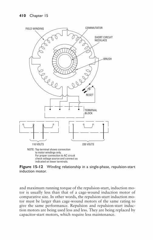
P1: GDZ/FFX P2: GDZ/FFX QC: GDZ/FFX T1: GDZ
GB076-15 GB076-Miller-Sample July 15, 2004 18:31 Char Count= 0
410 Chapter 15
110 VOLTS 220 VOLTS
TERMINALBLOCK
RESET
BRUSH
SHORT CIRCUITNECKLACE
COMMUTATORFIELD WINDING
Top terminal shows connectionto motor windings only.For proper connection to AC circuitcheck voltage source and connect asindicated on lower terminals.
NOTE:
Figure 15-12 Winding relationship in a single-phase, repulsion-startinduction motor.
and maximum running torque of the repulsion-start, induction mo-tor is usually less than that of a cage-wound induction motor ofcomparative size. In other words, the repulsion-start induction mo-tor must be larger than cage-wound motors of the same rating togive the same performance. Repulsion and repulsion-start induc-tion motors are being used less and less. They are being replaced bycapacitor-start motors, which require less maintenance.
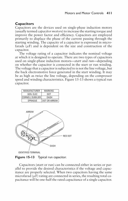
P1: GDZ/FFX P2: GDZ/FFX QC: GDZ/FFX T1: GDZ
GB076-15 GB076-Miller-Sample July 15, 2004 18:31 Char Count= 0
Motors and Motor Controls 411
CapacitorsCapacitors are the devices used on single-phase induction motors(usually termed capacitor motors) to increase the starting torque andimprove the power factor and efficiency. Capacitors are employedprimarily to displace the phase of the current passing through thestarting winding. The capacity of a capacitor is expressed in micro-farads (µF) and is dependent on the size and construction of thecapacitor.
The voltage rating of a capacitor indicates the nominal voltageat which it is designed to operate. There are two types of capacitorsused on single-phase induction motors—start and run—dependingon whether the capacitor is connected in the start or run winding.The voltage that a capacitor is subjected to is not the line voltage, butthe back electromotive force generated in the start winding. It maybe as high as twice the line voltage, depending on the compressorspeed and winding characteristics. Figure 15-13 shows a typical runcapacitor.
ARROW
RED DOT
DASH
IDENTIFIED TERMINAL
MANUFACTURERGEN. ELEC
CORNELL DUBILIERSPRAGUE
MARKINGDOTDASH
DOT OR ARROW
Figure 15-13 Typical run capacitor.
Capacitors (start or run) can be connected either in series or par-allel to provide the desired characteristics if the voltage and capac-itance are properly selected. When two capacitors having the samemicrofarad (µF) rating are connected in series, the resulting total ca-pacitance will be one-half the rated capacitance of a single capacitor.
P1: GDZ/FFX P2: GDZ/FFX QC: GDZ/FFX T1: GDZ
GB076-15 GB076-Miller-Sample July 15, 2004 18:31 Char Count= 0
412 Chapter 15
The formula for determining capacitance (µF) when capacitors areconnected in series is as follows:
1µFtotal
= 1µF1
+ 1µF2
When capacitors are connected in parallel, their rating is equalto the sum of their individual capacities, while their voltage ratingis equal to the smallest rating of the individual capacitors.
ExampleWhat is the combined capacity of three capacitors of 7-, 8-, and9-µF capacity, respectively, when connected in series?
SolutionThe formula for series connected capacitors is as follows:
(Using a calculator)
1CT
= 17
+ 18
+ 19
or,
1CT
= 0.014285 + 0.125 + 0.011111
1CT
= 0.037896
or,
CT = 2.6387435 µF
ExampleWhat is the total capacity of four capacitors of 10-, 15-, 25-, and30-µF capacitance when connected in parallel?
SolutionSince the following is true:
C = C1 + C2 + C3 + C4
substituting numerical values gives the following:
C = 10 + 15 + 25 + 30 = 80µF
The capacitor for capacitor-start motors is an electrolytic type,and the number of starts and stops per minute is limited. Runningcapacitors, however, are generally oil-filled and may stay on the linecontinuously.
P1: GDZ/FFX P2: GDZ/FFX QC: GDZ/FFX T1: GDZ
GB076-15 GB076-Miller-Sample July 15, 2004 18:31 Char Count= 0
Motors and Motor Controls 413
AC Motor ControlsSquirrel Cage MotorsThe functions of control apparatus for squirrel cage motors are asfollows:
� Starting the motor on full voltage or reduced voltage� Stopping the motor� Disconnecting the motor on voltage failure� Limiting the motor load� Changing the direction of rotor rotation� Starting and stopping the motor at fixed points in a given cycle
of operation, at the limit of travel of the load, or when selectedtemperature or pressures are reached
Where multispeed motors are involved, the following functions maybe added:
� Changing the speed of rotation (rpm)� Starting the motor with a definite speed sequence
Control devices that permit motors to be stopped are as follows:
� Under the direction of an operation� Under the control of a pilot-circuit device (such as a ther-
mostat, pressure regulator, float switch, limit switch, or camswitch)� Under the control of protective devices that will disconnect the
motor under detrimental overload conditions or upon failureof voltage or lost phase (see Figure 15-14)
Starting squirrel cage motors in industrial plants is usually ac-complished by means of one of the following methods:
� Directly across the line� Use of autotransformers (compensators)� By resistance in series with the stator winding� Use of a step-down transformer
Squirrel cage motors of 5 horsepower or less are generally startedwith line switches connecting the motors directly across the line.The switches are usually equipped with thermal devices that openthe circuit when overloads are carried beyond predetermined values.
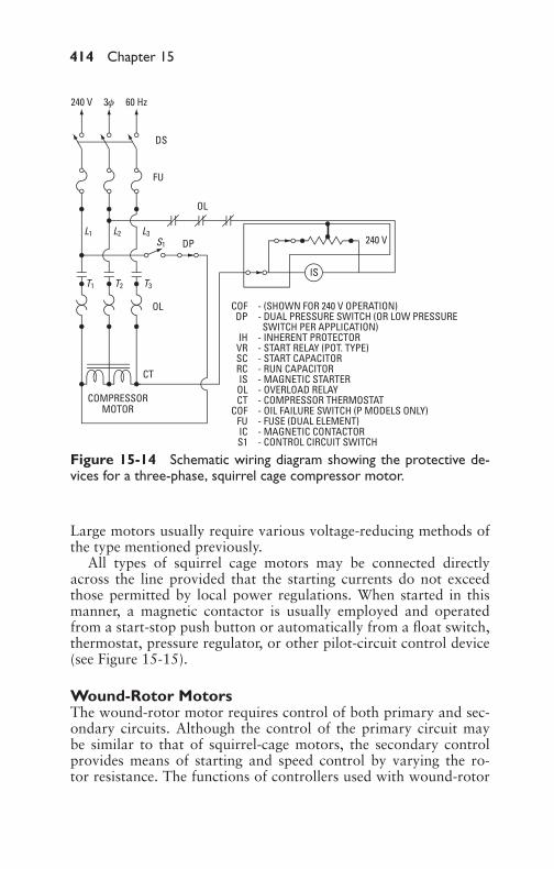
P1: GDZ/FFX P2: GDZ/FFX QC: GDZ/FFX T1: GDZ
GB076-15 GB076-Miller-Sample July 15, 2004 18:31 Char Count= 0
414 Chapter 15
Figure 15-14 Schematic wiring diagram showing the protective de-vices for a three-phase, squirrel cage compressor motor.
Large motors usually require various voltage-reducing methods ofthe type mentioned previously.
All types of squirrel cage motors may be connected directlyacross the line provided that the starting currents do not exceedthose permitted by local power regulations. When started in thismanner, a magnetic contactor is usually employed and operatedfrom a start-stop push button or automatically from a float switch,thermostat, pressure regulator, or other pilot-circuit control device(see Figure 15-15).
Wound-Rotor MotorsThe wound-rotor motor requires control of both primary and sec-ondary circuits. Although the control of the primary circuit maybe similar to that of squirrel-cage motors, the secondary controlprovides means of starting and speed control by varying the ro-tor resistance. The functions of controllers used with wound-rotor

P1: GDZ/FFX P2: GDZ/FFX QC: GDZ/FFX T1: GDZ
GB076-15 GB076-Miller-Sample July 15, 2004 18:31 Char Count= 0
Motors and Motor Controls 415
SI
440 V,
DS
FU
120 or 240 VSEPARATE CONTROL CIRCUIT VOLTAGE
OL
OL
CT
COMPRESSORMOTOR
DP
480 V, or 550 V
130 V
240 V
3f 60 Hz
L1 L2 L3
T1 T2 T3
S1IS
# 1# 2
# 3
COF440 V 480 V–10 HP & LARGER ONLY
550 V–75 HP & LARGER ONLY
FOR120 V240 V
CONTROL VOLTAGE CIRCUIT
CONNECT LEADS #1 & #2#2 & #3
IS - MAGNETIC STARTEROL - OVERLOAD RELAYCT - THERMOSTAT
SUPPLIED ON 15IIAND LARGER ONLY
Figure 15-15 Schematic wiring diagram showing the wiring arrange-ment for a typical compressor motor with separate control-circuit volt-age.
motors are as follows:� To start the motor without damage or undue disturbance to
the motor, driven machine, or power supply� To stop the motor in a satisfactory manner� To reverse the motor� To run the motor at one or more predetermined speeds below
synchronous� To handle an overhauling load satisfactorily� To protect the motor
The various types of controllers utilized may be divided into thefollowing groups, depending on the size and function of the motor:� Face-plate starters� Face-plate speed regulators� Multiswitch starters
P1: GDZ/FFX P2: GDZ/FFX QC: GDZ/FFX T1: GDZ
GB076-15 GB076-Miller-Sample July 15, 2004 18:31 Char Count= 0
416 Chapter 15
� Drum controllers� Motor-driven drum controllers� Magnetic starters
By the use of external resistors in the slip-ring rotor windings, awide variation in rotor resistance can be obtained with a resultantvariation in acceleration characteristics. Thus, a heavy load can bestarted as slowly as desired, without a jerk, and can be acceleratedsmoothly and uniformly to full speed. It is merely a matter of supply-ing the necessary auxiliary control equipment to insert sufficientlyhigh resistance at the start and gradually reducing this resistance asthe motor picks up speed. Figure 15-16 shows an automatic con-trolled starter for wound-rotor motor operation.
Many power companies have established limitations on theamount of current motors may draw at starting. The purpose isto reduce voltage fluctuations and prevent flickering of lights. Be-cause of such limitations, the question of starting current is often thedeciding factor in choosing wound-rotor motors instead of squirrelcage motors. Wound-rotor motors with proper starting equipmentdevelop a starting torque equal to 150 percent of full-load current.This compares very favorably with squirrel cage motors, one typeof which requires a starting current of as much as 600 percent offull-load current to develop the same starting torque of 150 percent.
This type of motor is suitable where the speed range required issmall, where the speeds desired do not coincide with a synchronousspeed of the line frequency, or where the speed must be graduallyor frequently changed from one value to another. The wound-rotormotor also gives high starting torque with a low current demandfrom the line, but it is not efficient when used for a large proportionof the time at reduced speed. Power corresponding to the percentdrop in speed is consumed in the external resistance at slow speedwithout doing any special work.
Synchronous MotorsTo make a synchronous motor self-starting, a squirrel cage windingis usually placed on the rotor of the machine. After the motor comesup to the speed that is slightly less than synchronous, the rotor isenergized. When synchronous motors are started, their DC fields arenot excited until the rotor has reached practically full synchronousspeed. The starting torque required to bring the rotor up to thisspeed is produced by induction.
In addition to the DC winding on the field of synchronous motors,they are generally provided with a damper or amortisseur winding.
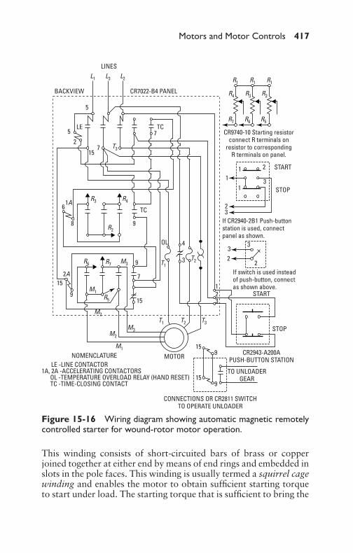
P1: GDZ/FFX P2: GDZ/FFX QC: GDZ/FFX T1: GDZ
GB076-15 GB076-Miller-Sample July 15, 2004 18:31 Char Count= 0
Motors and Motor Controls 417
LINESL1 L3 L2 R1
R4 R3
R3 R4
R6
R5
R7 M3
M1
M2
M2
M1
M3
T1
T1
T2
T2
T3
R2
R2
R5R6R7
R1 R1
T3
BACKVIEW CR7022-B4 PANEL
5
5
27
LE TC
15
7
TC
98
61A
2A15
159
9
7
MOTOR15
15
9
9
OL 4
3
33
22
23
1
STOP
START
TO UNLOADERGEAR
CR2943-A200APUSH-BUTTON STATION
CONNECTIONS OR CR2811 SWITCHTO OPERATE UNLOADER
NOMENCLATURELE -LINE CONTACTOR
1A, 2A -ACCELERATING CONTACTORSOL -TEMPERATURE OVERLOAD RELAY (HAND RESET)TC -TIME-CLOSING CONTACT
CR9740-10 Starting resistorconnect R terminals on
resistor to correspondingR terminals on panel.
START
STOP
1
11
2
23
3
If CR2940-2B1 Push-buttonstation is used, connectpanel as shown.
If switch is used insteadof push-button, connectas shown above.
Figure 15-16 Wiring diagram showing automatic magnetic remotelycontrolled starter for wound-rotor motor operation.
This winding consists of short-circuited bars of brass or copperjoined together at either end by means of end rings and embedded inslots in the pole faces. This winding is usually termed a squirrel cagewinding and enables the motor to obtain sufficient starting torqueto start under load. The starting torque that is sufficient to bring the

P1: GDZ/FFX P2: GDZ/FFX QC: GDZ/FFX T1: GDZ
GB076-15 GB076-Miller-Sample July 15, 2004 18:31 Char Count= 0
418 Chapter 15
motor up to synchronous speed is termed the pull-in torque. Themaximum torque that the motor will develop without pulling outof step is termed the pull-out torque.
Reduced-voltage starting differs from the across-the-line methodin that reduced voltage is first applied to the motor by means of atransformer (usually an autotransformer). In this method of start-ing, full voltage is applied only after the motor has reached nearlysynchronous speed.
Reactance-motor starting is similar to reduced-voltage methods,except that the first step is obtained by reactance in series with themotor armature instead of by autotransformers. In the reactancemethod, more current is required from the line for the same torqueon the first step than when compensators are used. It has an advan-tage, however, in that no circuit opening is required when the motoris transferred to running voltage, the transfer being accomplishedby short-circuiting the reactance.
Single-Phase Motor ControlsSingle-phase motors are usually controlled by means of line startersor contactors, which may be either manual or magnetic. The com-pressor contactor is a switch that is used on both single- and three-phase units to open or close the power circuit to the compressor.Unlike a starter, a contactor does not include overload protectivedevices. Contactors are used on single-phase systems and on somethree-phase systems. The trend is to eliminate contactor overloadprotectors and eventually use only inherent compressor-motor pro-tective devices on all systems (including both single- and three-phaseunits). Under normal operating conditions, the contactor is con-trolled by the thermostat, although the contactor coil can be de-energized by the pressure switch or compressor inherent overloadprotectors (see Figure 15-17).
The motor starter is a switch that performs the same functionas a contactor, except that it includes (as an integral part) overloadprotective devices. These overload protective devices are normallyreferred to as heaters because, with abnormal motor amperage, thedevice warps from the heat developed by the additional current andbreaks a contact, thereby opening the compressor control circuit.This, in turn, allows the starter to break its contacts and stop thecompressor.
Overload ProtectorsTwo types of inherent overload protection are provided on mo-tor compressors: thermal and combined thermal and current. The

P1: GDZ/FFX P2: GDZ/FFX QC: GDZ/FFX T1: GDZ
GB076-15 GB076-Miller-Sample July 15, 2004 18:31 Char Count= 0
Motors and Motor Controls 419
1f, 60 Hz208/230 V
120 V1f,60 HzDS
DP
IH
IC
SIIC
IC
VRVR
DP
IHIH IH
CTRC SCVR SCVR
FU FUL2 L2
S1
T2 T2T1 T1
L1 L1
COMPRESSORMOTOR
COMPRESSORMOTOR
DP - DUAL PRESSURE SWITCH (OR LOW PRESSURE SWITCH PER APPLICATION)IH - INHERENT PROTECTORVR - START RELAY (POT. TYPE)SC - START CAPACITORRC - RUN CAPACITORIS - MAG. STARTER (1/2, 3/4 , TO 1 HP & LARGER ONLY)
OL - OVERLOAD RELAYCT - COMPRESSOR THERMOSTATCOF - OIL FAILURE SWITCH
(P MODELS ONLY)FU - FUSE (DUAL ELEMENT)IC - MAGNETIC CONTACTORS1 - CONTROL CIRCUIT SWITCH
Figure 15-17 Wiring diagram showing single-phase-capacitor motorwith starting and running protective devices.
thermal type is sensitive to temperature only, whereas the thermal-and-current type is sensitive to both motor current and temperature.
The current-and-thermal type of overload protector is affectedby both compressor-shell temperature and motor current. This typeof protector is designed to carry full motor current and is, therefore,wired in the power circuit of the compressor.
Start RelaysSingle-phase motor relays are employed to obtain automatic start-ing. Since it is necessary to provide current through the start windingunder predetermined conditions, there must be an automatic devicefor accomplishing this. The device is the start relay. With the current-type relay, a spring is used to hold the contact points open. Whenthe motor is inoperative, the contact points are open. As currentstarts to flow through the relay and running winding, the holdingcoil is energized, thus overcoming the spring tension and closing thecontact points. At this time, current is then also directed through
P1: GDZ/FFX P2: GDZ/FFX QC: GDZ/FFX T1: GDZ
GB076-15 GB076-Miller-Sample July 15, 2004 18:31 Char Count= 0
420 Chapter 15
the start-capacitor and start winding. As the speed of the motorincreases, the holding-coil current reduces until it reaches the pointwhere the spring tension overcomes the voltage and opens the con-tact points. To operate the motor, the run winding remains in thecircuit. Normally, one side of the current coil is connected insidethe relay, and only three external terminals are furnished. However,when a three-terminal protector is used, both current coil connec-tions must be made externally, and a relay having four terminals orwires is used.
With the potential-type relay, the contact points are held closedby means of spring tension. Therefore, when the motor is not in op-eration, the contact points are always closed. As the current startsto flow through the closed contacts of the relay, it is directed im-mediately through the start- capacitor and start winding, as wellas through the run winding. The voltage in the holding coil (whichis connected across the motor start winding) increases with an in-crease in speed. As the motor approaches full speed, the holding-coilvoltage overcomes the spring tension and opens the contact points,thus removing the starting capacitor and starting winding from thecircuit.
Compressor Motor ControlsCompressor motor controls may be divided into two classes: tem-perature and pressure.
Temperature-Motor ControlThe temperature-motor control serves as a connecting link betweenthe motor and the evaporator. This control mechanism consists es-sentially of a thermostatic bulb clamped to the evaporator, togetherwith a capillary tube and attached bellows. These three intercon-nected elements are assembled and charged with a few drops ofrefrigerant (such as sulfur dioxide or similar highly volatile fluid).An electrical switch is operated through linkage by the movementof the bellows. In this manner, the electrical motor circuit is closedon rising temperature and opened on falling temperature.
In operation, as the temperature of the bulb increases, gas pres-sure in the bulb-bellows assembly increases and the bellows pushthe operating shaft upward, operating the toggle or snap mecha-nism. Consequently, the upward travel of the shaft finally pushes thetoggle mechanism off center and the switch snaps closed, startingthe compressor. As the compressor runs, the control bulb is cooledgradually, reducing the pressure in the bulb-bellows system. Thisreduction of bellows pressure allows the spring to push the shaft
P1: GDZ/FFX P2: GDZ/FFX QC: GDZ/FFX T1: GDZ
GB076-15 GB076-Miller-Sample July 15, 2004 18:31 Char Count= 0
Motors and Motor Controls 421
slowly downward until it has finally traveled far enough to pushthe toggle mechanism off-center in the opposite direction, snappingthe switch open and stopping the compressor. The control bulb thenslowly warms up until the motor again starts and the cycle repeatsitself. The thermostatic control is set to close the compressor circuitat a certain evaporator temperature and open the circuit at anotherpredetermined temperature. In this manner, any desired cabinet tem-perature may be maintained.
Pressure-Motor ControlThe pressure-motor control device is similar in construction to thetemperature control, with the exception that the temperature bulband capillary tube are replaced by a pressure tubing connected di-rectly to the low-pressure control source and an electrical switchoperated through linkage by the movement of the bellows. In thepressure-motor control method, the compressor operation is onlyindirectly dependent on the temperature of the refrigeration load,but is controlled by refrigerant pressure at the point of controllocation.
Solenoid ValvesSolenoid valves are frequently used in refrigeration systems for con-trol of gas and liquid flow. In general, solenoid valves are used tocontrol the refrigerant flow into the expansion valve or the gas flowfrom the evaporator when the evaporator or fixture has reached thedesired temperature. When used as liquid stop valves, they shouldbe installed in the liquid line and as close to the expansion valve aspossible to prevent bubbling and subsequent reduction in expansion-valve capacity.
In some installations, a solenoid valve is operated directly by athermostat located at the load point, and the compressor motor iscontrolled independently by a low-pressure switch. It is importantto furnish the solenoid-valve manufacturer with the electrical char-acteristics of the circuit on which the valve is to operate. The maxi-mum pressure at which the valve is to open should also be specifiedbecause excessive pressure may prevent the valve from opening.
Condensing-Water ControlsAutomatic control of condenser-water flow is often necessary to pre-vent water wastage. Such control may be provided by using solenoidvalves or a pressure control valve. In the case of solenoid-valve in-stallation, the operation is dependent upon the starting and stoppingof the compressor motor, whereas with a pressure-control valve, theoperation is dependent entirely upon condenser pressure.
P1: GDZ/FFX P2: GDZ/FFX QC: GDZ/FFX T1: GDZ
GB076-15 GB076-Miller-Sample July 15, 2004 18:31 Char Count= 0
422 Chapter 15
Belt DrivesOpen-type motors usually require a belt connection between themotor and compressor since the motor speed is normally too highto allow a direct compressor coupling. For belt-drive compressors,speed is determined by the size of the motor pulley, since the com-pressor pulley (flywheel) is normally fixed. The relative speeds of themotor and compressor are in direct relation to the size of the motorpulley and the compressor flywheel. The desired pulley size, or theresulting compressor speed, may be calculated from the followingrelation:
Compressor rpm
= motor-pulley diam. × motor speed (rpm)compressor-pulley diam.
Motor-pulley diam.
= compressor speed (rpm) × compressor-pulley diam.motor speed (rpm)
ExampleFind the motor-pulley diameter required when a 1750-rpm motor isto be used to drive a compressor having an 8-inch diameter pulleywhen the compressor speed is 500 rpm.
SolutionThe diameter of the motor pulley is obtained by substituting valuesas follows:
Motor-pulley diameter = 500 × 81750
or 21/4 in (approx.)
The desired driven speed in the preceding formula should be in-creased by 2 percent to allow for belt slip. The diameter of anysuitable motor pulley at any motor speed may easily be calculatedby inserting values of compressor-pulley diameter in a manner sim-ilar to the previous example.
Motor MaintenanceModern methods of design and construction have made the electricmotor one of the least complicated and most dependable forms ofmachinery in existence. Proper maintenance is very important andmust be given careful consideration if the best performance andlongest life are to be expected from the motor. From the standpoint

P1: GDZ/FFX P2: GDZ/FFX QC: GDZ/FFX T1: GDZ
GB076-15 GB076-Miller-Sample July 15, 2004 18:31 Char Count= 0
Motors and Motor Controls 423
of performance, the two major features are proper lubrication andthe care given to the insulation.
The design of bearings and bearing housings of motors has im-proved in the last few years. The point has now been reached wherethe bearings of modern motors, whether sleeve, ball, or roller, re-quire only infrequent attention. This advance in lubrication methodshas not yet been fully appreciated.
There may have been some necessity for more frequent atten-tion in the case of older designs. They had housings less tight thanthose on modern machines. Oiling and greasing of new motors arequite often entrusted to uninformed and careless attendants, withthe result that oil or grease is copiously and frequently applied tothe outside (as well as the inside) of bearing housings. Some of theexcess lubricant is carried into the machine and lodges on the wind-ings, where it catches dirt and thereby hastens the ultimate failureof the insulation.
Modern design provides for a plentiful supply of oil or grease heldin dust- and oil-tight housings. If the proper amount of a suitablelubricant is applied before starting, there should be no need to refillthe housings for several months, even in dusty places. Periodic andreasonable attention to modern bearings of any type will lead towardlonger life of both bearings and insulation.
Horsepower CalculationsThe formulas dealing with calculations of electric-motor capacityrequirements under various conditions of service are given in thefollowing sections.
Motor Horsepower Calculated from Meter ReadingsFollowing are calculations to determine motor horsepower frommeter readings.
DC Motors
HP = volts × amperes × efficiency746
Single-Phase AC Motors
HP = volts × amperes × efficiency × power factor746
Two-Phase AC Motors
HP = volts × amperes × efficiency × power factor × 2746

P1: GDZ/FFX P2: GDZ/FFX QC: GDZ/FFX T1: GDZ
GB076-15 GB076-Miller-Sample July 15, 2004 18:31 Char Count= 0
424 Chapter 15
Three-Phase AC Motors
HP = volts × amperes × efficiency × power factor × 1.73746
Horsepower Calculated from Load (Mechanics’ Data)Following are calculations to determine horsepower from load.
Constant Speed1. Rotational horsepower:
HP = torque (lb/ft) × speed (rpm)5250
2. Prony-brake horsepower:
HP = 2 × 3.1416 × lb applied at 1-ft radius × rpm33,000
3. Linear horsepower:
HP = force (lb) × velocity (ft/min)33,000
Acceleration from Zero to Full Speed1. Rotational horsepower:
HP = inertia (WR2) × rpm1.62 × 106t (in seconds to come up to speed)
2. Linear horsepower:
HP = inertia (W) × rpm2
6.38 × 10⁷t (in seconds to come up to speed)
Horsepower Calculations for SpecificApplications (Approximate)Following are calculations to determine horsepower for specific ap-plications.
Pumping Water
HP = gallons/min × total dynamic head (ft)3960 × pump efficiency

P1: GDZ/FFX P2: GDZ/FFX QC: GDZ/FFX T1: GDZ
GB076-15 GB076-Miller-Sample July 15, 2004 18:31 Char Count= 0
Motors and Motor Controls 425
Moving Air
HP = volume × pressure (lb/ft2)30,000 × efficiency
HP = 5.2 × volume (ft3/min) × head (in H2O)33,000 × efficiency
Compressing GasesFor one working stroke per revolution (single-acting):
HP = PLAN33,000 × 0.90
where the following is true:
P = effective pressure in cylinders, psiL = length of stroke, ft
A = area of piston, in in2
N = no. of rpms
Power-Conversion FactorsFollowing are power-conversion factors:� 1 kW—Equivalent to 3412.75 Btu; 860 cal; 1.34048 hp� 1 hp—Equivalent to 0.746 kW; 2546 Btu; 642 cal
Troubleshooting GuideThe troubleshooting guides shown in Table 15-1 will assist in trou-bleshooting air-conditioning motors and their controls. It should benoted, however, that although the trouble may differ at times fromthat given in this section, experience will usually reveal the exactcause, after which the possible remedy and its correction may becarried out.
SummaryDirect-current motors are generally classified as series-, shunt-, andcompound-wound. Series motors are those in which the field coiland armature are connected in series and current flows throughboth the field and armature. In shunt-wound motors, the field coiland armature are connected in parallel. The compound-wound mo-tor has separate field windings. One is usually a predominant fieldand is connected in parallel with the armature circuit; the other isconnected in series.

P1: GDZ/FFX P2: GDZ/FFX QC: GDZ/FFX T1: GDZ
GB076-15 GB076-Miller-Sample July 15, 2004 18:31 Char Count= 0
426 Chapter 15
Table 15-1 Electrical System Troubleshooting Guide
System Possible Cause Possible Remedy
Compressordoes notoperate.
Electrical controls. Check fuses, relays, andcapacitors.
Unit runs butfails to cool.
Insufficient warm-upperiod of unit.
Allow 30 minutes runningtime before a decision is made.
Compressor motorreset out. Unit hasoperated for sometime, but little or nocooling is experienced.
Push reset button forcompressor. Make unitreplacement only after acomplete check is made ofsystem.
Condensatefan will notrun.
Reset button may bestuck.
Check reset button located onfan motor.
Fan striking shroud. Turn fan by hand to see if itrotates freely.
Bearings tight. Motorburned out.
Replace fan motor.
Evaporator fanwill not run.
Reset button out. Check motor-reset button.
Faulty capacitor. Use test-cord procedure fortesting evaporator fan-motorcircuit.
Motor burned out. Replace motor.
Unit vibrates. Unit seems noisy andvibrates too much.
Check to see if all shippingbolts have been removed.Check for loose fan on motorshaft. Unit must be level on allfour sides and bearing on fourcorners.
Unit does notcool properly.
Compressor seems tobe operating but littlecooling is experienced.
Check intake-air filter forexcess dust. Checkthermostatic control settingwith a good thermometer.
Low line voltage. Low line voltage results inhigh-current drain andhigh-head pressures, whichultimately reduces capacity ofthe compressor.
(continued)
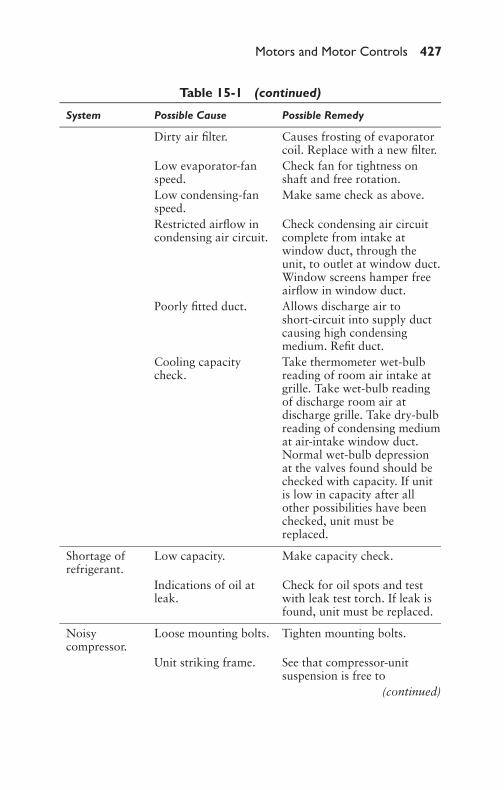
P1: GDZ/FFX P2: GDZ/FFX QC: GDZ/FFX T1: GDZ
GB076-15 GB076-Miller-Sample July 15, 2004 18:31 Char Count= 0
Motors and Motor Controls 427
Table 15-1 (continued)
System Possible Cause Possible Remedy
Dirty air filter. Causes frosting of evaporatorcoil. Replace with a new filter.
Low evaporator-fanspeed.
Check fan for tightness onshaft and free rotation.
Low condensing-fanspeed.
Make same check as above.
Restricted airflow incondensing air circuit.
Check condensing air circuitcomplete from intake atwindow duct, through theunit, to outlet at window duct.Window screens hamper freeairflow in window duct.
Poorly fitted duct. Allows discharge air toshort-circuit into supply ductcausing high condensingmedium. Refit duct.
Cooling capacitycheck.
Take thermometer wet-bulbreading of room air intake atgrille. Take wet-bulb readingof discharge room air atdischarge grille. Take dry-bulbreading of condensing mediumat air-intake window duct.Normal wet-bulb depressionat the valves found should bechecked with capacity. If unitis low in capacity after allother possibilities have beenchecked, unit must bereplaced.
Shortage ofrefrigerant.
Low capacity. Make capacity check.
Indications of oil atleak.
Check for oil spots and testwith leak test torch. If leak isfound, unit must be replaced.
Noisycompressor.
Loose mounting bolts. Tighten mounting bolts.
Unit striking frame. See that compressor-unitsuspension is free to
(continued)

P1: GDZ/FFX P2: GDZ/FFX QC: GDZ/FFX T1: GDZ
GB076-15 GB076-Miller-Sample July 15, 2004 18:31 Char Count= 0
428 Chapter 15
Table 15-1 (continued)
System Possible Cause Possible Remedy
swing without striking theframe.
Compressor unit itselfnoisy.
Operate compressor a shorttime with fans off to determineif noise is emanating fromcompressor.
Unit not level. Check complete unit forleveling and stability. Ifcompressor still proves noisy,complete unit must bereplaced.
Unit fails tostart.
Low voltage. Check voltage at plugreceptacle. Check wire sizeand length of run. Checkpower-supply voltage atservice switch or meter.
Blown fuses. Check fuses.
Alternating-current motors are divided into two general classes:polyphase and single-phase. Polyphase motors are classified accord-ing to windings as squirrel cage induction, wound-rotor induction,and synchronous motors. Single-phase motors are classified accord-ing to their construction as split-phase, capacitor-start, permanent-split capacitor, repulsion induction, and repulsion-start induction.
The two basic types of overload protection devices are the thermaltype and the thermal-and-current type. The thermal type is sensitiveto temperature only, and the thermal-and-current type is sensitive toboth temperature and current. Temperature-motor controls are alsoused in connection with protection devices. This control mechanismconsists essentially of a thermostatic bulb clamped to the evaporatortogether with a capillary tube. This assembly is charged with a fewdrops of refrigerant fluid, which operates switches through properlinkage and attached bellows.
Solenoid valves are used frequently in refrigeration systems tocontrol gas and liquid flow. The solenoid valves are used to controlrefrigerant flow into expansion valves. In some installations, thevalves are operated directly by thermostats.
Review Questions1. What precautions should be observed when selecting a motor
for compressor devices?

P1: GDZ/FFX P2: GDZ/FFX QC: GDZ/FFX T1: GDZ
GB076-15 GB076-Miller-Sample July 15, 2004 18:31 Char Count= 0
Motors and Motor Controls 429
2. Why is alternating current preferred for compressor devicesinstead of direct current?
3. How are AC motors generally classified?4. Why are single-phase, fractional-horsepower motors used in
preference to polyphase motors in home air conditioning?5. Describe the construction principles of a squirrel cage motor.6. In what respect does the rotor winding in a squirrel cage motor
differ from the rotor winding in a wound-rotor motor?7. Why are synchronous motors seldom used in the field of resi-
dence air conditioning?8. What is the normal size limit of single-phase motors?9. How are single-phase motors designed?
10. What is the function of the auxiliary winding in a split-phasemotor?
11. Explain the operation of a capacitor motor.12. What are the operating characteristics of a repulsion-start in-
duction motor?13. What is the combined capacity of three capacitors, each hav-
ing a capacity of 20µF, when connected in series and whenconnected in parallel?
14. Name the various control methods used on squirrel cage andon wound-rotor motors.
15. How are single-phase, fractional-horsepower motors usuallycontrolled?
16. Name two types of overload protectors as employed in acompressor-motor drive.
17. How do the temperature controls function to regulate motoroperation?
18. How is a synchronous motor made self-starting?19. What is the difference between three-phase and single-phase
motors?20. What is meant by a motor’s pull-in torque?

P1: GDZ/FFX P2: GDZ/FFX QC: GDZ/FFX T1: GDZ
GB076-15 GB076-Miller-Sample July 15, 2004 18:31 Char Count= 0
430

P1: GDZ/FFX P2: GDZ/FFX QC: GDZ/FFX T1: GDZ
GB076-16 GB076-Miller-Sample July 15, 2004 5:20 Char Count= 0
Chapter 16MaintenanceOne of the essential elements in analyzing air-conditioning problemsis a thorough understanding of variations in pressure, temperature,volume, and heat-absorbing characteristics of the refrigerant in thevarious parts of the system. A malfunction may be caused by oneportion of the system, or by a combination of several portions. Forthis reason, it is necessary and advisable to check the more obviouscauses first.
Each part of the system has a certain function to perform. If anyindividual part does not function correctly and efficiently, the per-formance of the entire air-conditioning system will be affected. Thefollowing procedures will be of assistance to the service technicianwhen analyzing air-conditioning-system troubles.
General ProcedureWhen checking the refrigerant or electrical circuit of a unit, thefollowing information should be obtained first:
� Operating head pressure� Operating suction pressure� Amperage� Voltage� Evaporator air (cubic feet per minute) and dry- and wet-bulb
temperature differences� Condenser air (cubic feet per minute) and temperature differ-
ences
This information will indicate whether the unit is performingproperly. If not, it will show which part of the unit is the source oftrouble.
The suction and discharge pressures are checked by attachingthe test manifold to the service valve and the discharge gage to thedischarge service valve. Before reading the gage pressure, the servicevalves should be front-seated approximately one turn, and the gagehoses purged through the center tap of the test manifold. Voltage andamperage can be checked with a combination voltammeter at thecompressor terminals. Evaporator and condenser air can be checkedusing a draft gage. The air-temperature drop through the evaporatorand the temperature rise through the condenser can be obtained bythe use of thermometers. A sling psychrometer can be used to obtain
431
P1: GDZ/FFX P2: GDZ/FFX QC: GDZ/FFX T1: GDZ
GB076-16 GB076-Miller-Sample July 15, 2004 5:20 Char Count= 0
432 Chapter 16
the wet-bulb temperature of the evaporator air. Before any actionis taken, based on suction or head pressure, the unit should operateor stabilize for at least 20 minutes.
Head PressuresChecking the head pressure of a condensing unit is fully as impor-tant as checking the suction pressure. Often this item is overlookedwhen checking a job, and it may be the direct cause of the trouble.There is no shortcut or easy method of estimating what the headpressure should be because it is affected by speed, temperature ofthe condensing medium, and suction pressure.
Check for air or other noncondensable gases in the condensingunit. It is necessary to test the head pressure while the condens-ing unit is idle and after the liquid refrigerant in the receiver hascooled to the temperature of the condensing medium. On water-cooled condensing units, it is possible to open the water valve andallow an excess amount of water to pass through the condenser.On air-cooled condensing units, the belts may be removed to al-low the fan on the motor to cool the condenser to room tempera-ture.
A high pressure will indicate the presence of noncondensablegases that must be purged. This purging should be done from apoint near the top of the condenser, and, in many instances, must berepeated several times to remove all the air or other gases. Purgingheavily as soon as the condenser stops is especially effective becausethe noncondensable gases separate from the refrigerant only whilethe compressor is in operation. After properly purging a unit, it isstill possible to operate with head pressures that are higher thannormal, which may be caused by dirty air-cooled condensers or bylimed-up water-cooled condensers. In either instance, the condensershould be cleaned to get the proper transfer of heat between therefrigerant and the condensing medium.
Another cause of high head pressure is sometimes found with anexcess charge of refrigerant in the system. On air-cooled condensingunits, if the liquid refrigerant completely fills the receiver and par-tially fills the condenser, it will cut down on the effective condensersurface and high head pressure will result. On water-cooled units,this condition is also true where the liquid level is high enough tosubmerge part of the condenser tubes. In a great many instances,condensing-unit capacities have been so greatly reduced throughexcessive head pressures that it is impossible to obtain automaticdefrosting between cycles. The reason for this is that the runningtime increases to the point where there is no off time.

P1: GDZ/FFX P2: GDZ/FFX QC: GDZ/FFX T1: GDZ
GB076-16 GB076-Miller-Sample July 15, 2004 5:20 Char Count= 0
Maintenance 433
On air-cooled condensing units, the head or discharge pressurewill increase with an increase in ambient air temperature. Under nor-mal operating conditions, the condensing temperature will be from20◦F to 30◦F higher than the ambient temperature. If the differencebetween the ambient and the condensing temperatures is more than30◦F, the unit is operating with higher than normal head pressure.
In view of the preceding information, causes of high head pressureare usually as follows:
� Air or other noncondensable gas in the system� Inoperative condenser blower� Dirty air-cooled condensers or limed-up water-cooled con-
densers� Excess of refrigerant in the system
Suction PressureIn checking commercial installations, it is found that many units areoperating at suction pressures far below manufacturers’ specifica-tions because of incorrect setting of expansion valves or switches.Evaporators that operate in a starved condition will invariably oillog and cause a shortage of oil in the compressor crankcase, whichburns out connecting rods, main bearings, and seals. Many timesa service technician has assumed that the seal was the first failureand, as a result, the refrigerant and oil charge were lost with sub-sequent bearing failures. What actually happened was that the oilsupply was low in the crankcase because of oil-logged evaporators,thus causing the compressor body failures. To correct this condi-tion, the proper procedure is to check the superheat settings on theevaporator and either add refrigerant, or properly adjust the expan-sion valve to prevent this oil logging. Usually, when this is done,the oil will return to the compressor crankcase and the difficultywill be remedied. Changing the compressor body will not help thesituation.
Operating at low suction pressures also causes the compressor tooperate at much higher head temperatures because of the amountof vapor being condensed and the amount of heat contained in thisvapor. Where this heat becomes excessive, it will tend to increasea breakdown of oil in the refrigerant, as well as cause some gas-ket materials to flow (thus causing head leaks). When operatinga condensing unit at certain specified low temperatures, the mo-tor and compressor pulleys must be the proper size to obtain ratedcapacities.
P1: GDZ/FFX P2: GDZ/FFX QC: GDZ/FFX T1: GDZ
GB076-16 GB076-Miller-Sample July 15, 2004 5:20 Char Count= 0
434 Chapter 16
Back PressureNormally, the suction temperatures will be about 45◦F with a suc-tion pressure of about 42 psi for Freon-12 and about 76 psi forFreon-22. Light evaporator loading will cause a suction-pressure de-crease, while heavy evaporator loading will cause a suction-pressureincrease. It should be noted that if high suction pressure is accompa-nied by high discharge pressure, and the temperature of the air overthe evaporator and condenser is high, high inside and outside airtemperatures may be at fault. No malfunction might be indicated.
Causes of low back pressures are usually as follows:� Inoperative evaporator blower� Obstructed or dirty evaporator� Dirty air filter� Low refrigerant charge� Faulty expansion valve� Incorrect superheat setting
Refrigerant ChargeThe receiver in the air-cooled system stores additional refrigerantand may fill the receiver to a point where the liquid refrigerant willback up in the lower condenser tubes. This will reduce the heat-transfer efficiency of the condenser, causing high head pressure and,in turn, reducing the cooling capacity of the unit. There is no accu-rate way to tell if the unit is overcharged. However, if overchargingis suspected, the most effective method of checking and correctingit is to discharge some of the refrigerant from the system until alow charge is indicated, and then add refrigerant until a full chargeis indicated. A low refrigerant charge is indicated by low suctionpressure, a bubbling sight glass, or a hissing expansion valve. A lowrefrigerant charge will reduce the capacity or output of the refriger-ating unit.
To check the refrigerant charge in units equipped with sightglasses, the procedure is usually as follows. The appearance of largemasses of bubbles indicates the presence of both vapor and liquidrefrigerant, which means that the system is not fully charged andrequires additional refrigerant. When the system is fully charged,the sight glass should be completely clear, or just show intermittentgroups of fine bubbles.
If the unit is not furnished with a sight glass, the receiver maybe equipped with a liquid-level test valve. After operating thecompressor for 20 minutes, open this valve slightly. The appearance

P1: GDZ/FFX P2: GDZ/FFX QC: GDZ/FFX T1: GDZ
GB076-16 GB076-Miller-Sample July 15, 2004 5:20 Char Count= 0
Maintenance 435
of liquid and frosting of the valve indicates an adequate charge. Adischarge of gas only, or gas and liquid intermittently, indicates alow charge. A discharge of gas will not feel cold, while a dischargeof liquid will. The high side is shipped with the proper charge ofrefrigerant, and normally will not need additional refrigerant. Thecharge is given on the nameplate of the unit. An overcharged sys-tem will result in higher-than-normal head pressure. (This conditioncan be determined from the procedure outlined in the section HeadPressures, earlier in this chapter.)
Compressor Service ValvesCompressor suction and discharge valves (see Figure 16-1) are shut-off valves with a manually operated stem. The suction and discharge
PACKINGVALVE STEM
JAM NUT VALVE SEATS
VALVE STEMVALVE STEM
CAP VALVE
Figure 16-1 Exterior and interior view of a typical compressor suctionor discharge valve.

P1: GDZ/FFX P2: GDZ/FFX QC: GDZ/FFX T1: GDZ
GB076-16 GB076-Miller-Sample July 15, 2004 5:20 Char Count= 0
436 Chapter 16
service valves are used to isolate the compressor from the system forservicing, or to check the gage pressure on both the high and lowsides of the system. With the valve stem turned to the extreme coun-terclockwise position (or back-seated), the main port is open, whilethe opening to the gage port is closed. The unit should operate withthe main port open. By turning the valve stem to the extreme clock-wise position, the valve is front-seated. In this position, the main portis closed, leaving the gage port open to the compressor. At any in-termediate position, both the main port and the gage port are open.The valve stems on all service valves are protected from breakageand leakage by caps, which should be replaced after servicing of theunit is finished.
GagesGages used in servicing are low-pressure gages and high-pressuregages. The standard type of low-pressure gage is often called a com-pound gage because its construction permits a reading of both pres-sure (in pounds per square inch) and vacuum (in inches of mercury),as shown in Figure 16-2. A standard compound gage dial is grad-uated to record a pressure range of from 30 inches of vacuum to60 psi of pressure. The high-pressure gage is equipped with a dialfor measuring pressures of from 0 psi to 300 psi. Gages used inrefrigeration service should be graduated to read approximatelydouble the actual working pressure.
0
2030
3020
100
1040
50
60 300
270
240
210180
150120
90
60
30
VAC.
PRESS.C O M P O U N D
Figure 16-2 Typical compound pressure and plain pressure gage.(Courtesy General Electric Company.)

P1: GDZ/FFX P2: GDZ/FFX QC: GDZ/FFX T1: GDZ
GB076-16 GB076-Miller-Sample July 15, 2004 5:20 Char Count= 0
Maintenance 437
Figure 16-3 Typical combination gage set. (Courtesy Mueller Brass.)
Combination GagesA test gage set for testing manifolds (see Figure 16-3) consists essen-tially of two tee valves built into one valve body with stems extend-ing out on each end for handwheel operations. The tee valves areso constructed that the valve works only on the leg that is attachedto the tee. Thus, the opening or closing of the stem only affects thisone opening, with the other two openings on the valve being openat all times.
Adding RefrigerantTo add refrigerant, use the following procedure:
1. Attach the proper refrigerant drum to the center tap on thecharging manifold, as shown in Figure 16-4.
2. Adjust the manifold valves so that the refrigerant will flowthrough the suction gage into the suction-gage hose.
3. Attach the suction-gage hose to the charging fitting on thesuction service valve. Purge a small amount of refrigerant fromthe drum to remove any air trapped in hoses before tighteningthe fittings.

P1: GDZ/FFX P2: GDZ/FFX QC: GDZ/FFX T1: GDZ
GB076-16 GB076-Miller-Sample July 15, 2004 5:20 Char Count= 0
438 Chapter 16
SUCTION LINE
SPRINGSCALE
EXPANSIONVALVE
EVAPORATOR
LIQUID LINE
REFRIGERANTCYLINDER
CHARGING LINE
DISCHARGESERVICE VALVE
D
SUCTIONSERVICE
VALVE
C
EBA
CG PG
COMPRESSOR
CONDENSER
RECEIVER
LIQUID LINESERVICE
VALVE
Figure 16-4 Schematic diagram showing the connections for addingrefrigerant through the low side. (Courtesy Crocker-Wheeler Corporation.)
4. Set the refrigerant drum on scales to observe the rate of charg-ing in pounds of refrigerant.
5. Front-seat (close) the suction service valve. Ensure that the re-frigerant drum is in an upright position, and start the compres-sor. Open the valve on the refrigerant drum slightly. Throttlethe drum valve to keep the suction pressure below 45 psi forFreon-12 and 80 psi for Freon-22 on the suction gage to pre-vent compressor damage.
NoteSetting the drum in a pan of warm water will speed up the refrig-erant flow into the system.
6. If the system requires a full charge, charge the amount of re-frigerant in pounds shown on the unit nameplate. If only a

P1: GDZ/FFX P2: GDZ/FFX QC: GDZ/FFX T1: GDZ
GB076-16 GB076-Miller-Sample July 15, 2004 5:20 Char Count= 0
Maintenance 439
small amount of refrigerant is to be added, charge the systemfor a few seconds and then open the suction service valve andlet the system stabilize for about 5 minutes. If the system isstill undercharged, repeat the previous procedure.
Removing RefrigerantIf the system is overcharged, purge a small amount of refrigerantfrom the suction service-valve gage port. Close the gage port andallow the system to stabilize. Continue purging the system until thesystem becomes undercharged. Use the procedure in the precedingsection to correct the refrigerant charge in the system.
Adding OilTo add oil to the compressor, use the following procedure:
1. Pump down the unit. (Refer to the section System Pump Down,later in this chapter.)
2. Remove the suction line from the compressor.3. Pour the oil into the suction outlet of the compressor until
the oil level is approximately halfway up on the oil-level sightglass. Do not overcharge.
4. Replace the suction line.5. Operate the compressor for 20 minutes, and then recheck the
oil level.
Removing OilTo remove oil from the compressor, proceed as follows:
1. Pump down the unit. (See the section System Pump-Down,later in this chapter.)
2. Front-seat (close) the compressor suction, and discharge ser-vice valves.
3. Remove both the suction and discharge lines from the com-pressor.
4. Disconnect capillary tubes and all electrical connections fromthe compressor.
5. Remove nuts and mounting assemblies that secure the com-pressor to the unit.
6. Remove the compressor, and pour oil out of the suctionopening.
P1: GDZ/FFX P2: GDZ/FFX QC: GDZ/FFX T1: GDZ
GB076-16 GB076-Miller-Sample July 15, 2004 5:20 Char Count= 0
440 Chapter 16
System Pump-DownThe pump-down procedure is as follows:
1. Back-seat (open) the suction and discharge service valves.2. Ensure that the suction gage is connected to the suction service-
valve gage port and that the high-pressure gage is connectedto the discharge service-valve gage port.
3. Front-seat service valves slightly to purge the gage lines, andlet pressure into the gages.
4. Start the compressor and allow it to run.5. Remove the cover of the dual-pressure control, and block the
low-pressure contacts closed. This prevents the suction pres-sure from shutting off the unit when the pressure is pumpedbelow the normal cutout setting. To block the contacts, forcethe low-pressure control contacts into a closed position andinsert a nonmetallic object to keep the contacts closed duringpump-down procedure.
6. Close the liquid shutoff valve to retain all of the liquid in thehigh side of the system.
7. Watch the suction gage as the compressor is operating. Whenthe suction pressure has been reduced to 0 psi, stop the com-pressor. Normally the pressure will increase after this firstpump-down cycle. Start the compressor again, and repeat thisprocedure until suction pressure remains at 1 psi to 2 psi whenthe compressor is stopped. If the pressure stays at 0 psi afterthe pump-down, be sure the center port of the gage manifoldis capped. Then open both the valves on the gage manifoldslightly to allow the pressure from the discharge side of theunit to bleed into the suction side so that a 1 psi to 2 psi pres-sure remains in the suction side. Always have a slight positivepressure in the system when it is opened to the atmosphere toprevent air and moisture from being drawn into the system.
8. Front-seat (close) the suction and discharge service valves.9. The low side of the system can now be repaired.
10. Evacuate and install the new drier when the system is opened.11. When the unit is repaired, open the compressor suction and
discharge service valves.12. Start the compressor. After determining that the system is
operating satisfactorily, remove the nonmetallic object fromthe dual-pressure control and replace the cover. Backseat the

P1: GDZ/FFX P2: GDZ/FFX QC: GDZ/FFX T1: GDZ
GB076-16 GB076-Miller-Sample July 15, 2004 5:20 Char Count= 0
Maintenance 441
service valves, and then disconnect the gage manifold fromthe valves. Disconnect the fittings and replace the gage portcaps.
Purging System of NoncondensablesAir or noncondensable gases may enter the system during originalinstallation or at any time the system is opened for repair. Thesenoncondensables will result in increased head pressure and reducedcapacity. To remove air or noncondensable gases, pump down thesystem (see the section System Pump-Down, earlier in this chapter).Shut down the system for at least 20 minutes. The air or noncon-densables collect in the upper part of the receiver and can be purgedfrom the system by cracking the discharge service valve. After a shorttime period, close the discharge valve and start the unit. Check therefrigerant charge, since some of the refrigerant may have been lostduring the purging operation.
Leak TestTwo common methods to test for leaks are the halide-torch methodand the electronic leak detector.
Halide-Torch Method (For Freon Refrigerants)To test for leaks before the initial startup of a system, use the fol-lowing procedure:
1. Front-seat (close) the suction and discharge service valves ifthey are not already closed.
2. Attach the charging manifold suction hose to the process valve.3. Attach a drum of the proper refrigerant to the center port of
the charging manifold.4. Open the process valve and suction gage valve. Introduce
enough refrigerant into the system to build up the pressureas high as possible.
5. Close the process valve and suction gage valve.6. Test the system with a halide-leak detector (see Figure 16-5),
and then with a soap solution, if necessary, at all points whereconnections have been made. Make a complete check of alljoints before attempting any repairs, since the pressure in thesystem must be released to make a correction.
7. If leaks exist, disconnect the refrigerant drum hose from thecharging manifold.

P1: GDZ/FFX P2: GDZ/FFX QC: GDZ/FFX T1: GDZ
GB076-16 GB076-Miller-Sample July 15, 2004 5:20 Char Count= 0
442 Chapter 16
Tur n e r
BRORANE BRORANEBRORANEBRORANEBRORANEBRORANEBRORANEBRORANE
EBRORANEBRORANEBRORANEBRORANEBRORANE
BRORANEFUEL
Figure 16-5 Gas leak de-tection is easy. This sen-sitive halide detector pin-points Freon leaks in a shorttime. Used on all noncom-bustible refrigerant (Freon)leaks, the flame changescolor when the exact loca-tion of the leak is deter-mined. (Courtesy Tumer Corporation.)
8. Open the suction valve andsuction gage hose to purge therefrigerant from the system. Onrefrigerant Freon-12 systemswhere pressure is 50 psi or less,and Freon-22 systems wherepressure is 90 psi or less, the ex-pansion valve will open, allowingpiping from the expansion valveto the suction service valve topurge also. If pressure is higher, itis necessary to purge the low sidethrough the suction service valve.This can be accomplished byremoving the suction-valve gageport plug and carefully openingthe suction valve slightly. Whenthe gage reads 0 pounds of pres-sure, close the suction serviceand suction-gage valves.
9. Repeat this leak check until allleaks are found and repaired.
10. When repaired, close the suctionvalve and disconnect the charg-ing manifold from the unit.
11. Back-seat (open) the suction anddischarge service valves.
Electronic Leak DetectorAlthough leak testing with a halidetorch is considered satisfactory inmost instances, a more reliable test
is made by means of the electronic-type tester. This easy-to-use in-strument reduces the guesswork in leak testing because it is moresensitive, faster responding, and capable of detecting a leak eventhough the surrounding air may be contaminated.
The electronic detector contains an internal pump, which drawsair and leaking halogen tracer gas (halogen gases are chlorine,bromine, fluorine, and iodine, or any of their compounds) througha probe and hose as the probe is passed over leaking joints, gas-kets, welds, and so on. The air/gas mixture is drawn between twoelectrodes in the control unit—the ion emitter and collector.
P1: GDZ/FFX P2: GDZ/FFX QC: GDZ/FFX T1: GDZ
GB076-16 GB076-Miller-Sample July 15, 2004 5:20 Char Count= 0
Maintenance 443
The leak detector contains an automatic balance circuit so that aconstant or slowly changing contamination in the atmosphere willnot cause the lamp to flash. Refrigerant gas will cause the lamp toflash only when there is an abrupt increase of gas going into the tipof the probe (such as when the probe tip passes near a leak).
To check for a leak with the electronic detector, proceed as fol-lows:
1. Plug the test detector into a 120-volt AC outlet.2. Turn the sensitivity knob to the right and allow a 1-minute
warm-up.3. Check the operation by turning the sensitivity knob quickly
from one position to another, which should light the probelamp.
4. Probe for leaks, starting with maximum sensitivity.5. If the probe lamp lights twice for each leak, reduce the sensi-
tivity.6. Recheck the suspected leaks for confirmation.
After replacing a component in the refrigerating system, alwaystest all joints for leaks before recharging. The extra time it takesis negligible compared to the loss of a charge caused by a faultyconnection. Be sure to clean the excess soldering flux (if used) fromthe new joints before testing, since the flux could seal off pinholeleaks that would show up later.
For new refrigerants (such as R-134a used in car air-conditioningunits), use an electronic leak detector for more accurate results thanwith soap and water or the flame test.
Evacuating the SystemWhen necessary to remove the entire refrigerant charge from thesystem (as in the case when an exchange of compressor or anyother component of the condensing unit is necessary), proceed asfollows:
1. Front-seat (close) the suction and discharge service valves.2. Attach the charging manifold suction hose to the suction valve.3. Connect the vacuum pump to the center port on the charging
manifold.4. Start the vacuum pump and open the suction valve. Adjust
the test manifold valves so that the vacuum pump is open tothe suction valve. Evacuate the system to obtain the highestvacuum possible with the vacuum pump used.

P1: GDZ/FFX P2: GDZ/FFX QC: GDZ/FFX T1: GDZ
GB076-16 GB076-Miller-Sample July 15, 2004 5:20 Char Count= 0
444 Chapter 16
5. During the early stage of evacuation, it may be desired to shutoff the pump at least once to see if there is a rapid loss ofvacuum, indicating the presence of leaks in the system.
6. Time required for proper evacuation depends on the sys-tem and the vacuum pump. It is recommended that thevacuum pump be allowed to run for two hours or evenovernight after maximum vacuum is obtained to evacuate thesystem.
7. Close the charging manifold valve to the vacuum pump. Stopthe pump. Note the reading on the vacuum gage and allow thesystem to stand for 1 hour. If the vacuum has not decreased,the system is tight.
8. When the unit is checked and repaired, close the suction valveand disconnect the charging manifold from the valve.
9. To put the system in operation, back-seat (open) the suctionand discharge service valves.
10. Be sure you do not allow the refrigerant to escape into theatmosphere. This is forbidden by law and strictly enforced bythe Environmental Protection Agency (EPA).
Checking Compressor ValvesTo check the compressor valves, proceed as follows:
1. Front-seat (close) the suction service valve.2. Start the compressor and operate the unit until the compound
gage shows 15 inches of vacuum.3. Stop the compressor.4. Back-seat (open) the suction service valve slightly to permit
the vapor in the suction line to bring the gage reading back tozero. Close the valve.
5. If the pressure on the gage starts to increase, a discharge valveleak is indicated and the compressor should be replaced.
6. If the compressor will not pull at least 15 inches of vacuum onthe compound gage, a suction-valve leak is indicated and thecompressor should be replaced.
Troubleshooting GuideIn addition to the foregoing servicing details, Table 16-1 shows themost common operating faults that can occur in residential year-round air conditioning.
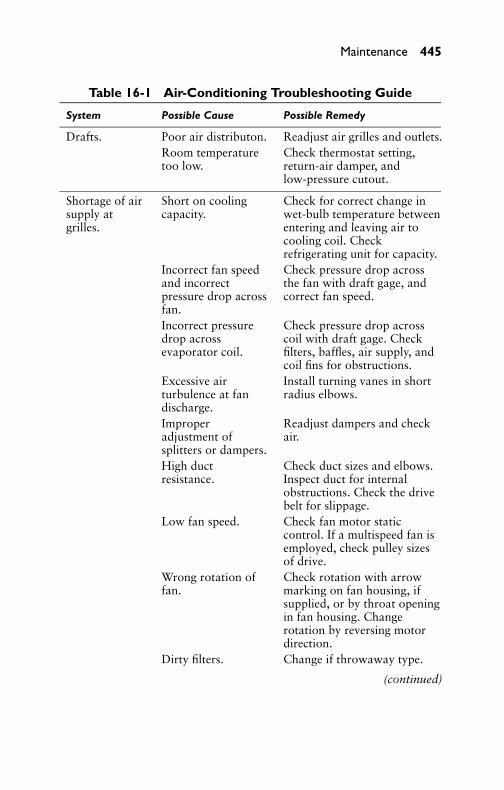
P1: GDZ/FFX P2: GDZ/FFX QC: GDZ/FFX T1: GDZ
GB076-16 GB076-Miller-Sample July 15, 2004 5:20 Char Count= 0
Maintenance 445
Table 16-1 Air-Conditioning Troubleshooting Guide
System Possible Cause Possible Remedy
Drafts. Poor air distributon. Readjust air grilles and outlets.Room temperaturetoo low.
Check thermostat setting,return-air damper, andlow-pressure cutout.
Shortage of airsupply atgrilles.
Short on coolingcapacity.
Check for correct change inwet-bulb temperature betweenentering and leaving air tocooling coil. Checkrefrigerating unit for capacity.
Incorrect fan speedand incorrectpressure drop acrossfan.
Check pressure drop acrossthe fan with draft gage, andcorrect fan speed.
Incorrect pressuredrop acrossevaporator coil.
Check pressure drop acrosscoil with draft gage. Checkfilters, baffles, air supply, andcoil fins for obstructions.
Excessive airturbulence at fandischarge.
Install turning vanes in shortradius elbows.
Improperadjustment ofsplitters or dampers.
Readjust dampers and checkair.
High ductresistance.
Check duct sizes and elbows.Inspect duct for internalobstructions. Check the drivebelt for slippage.
Low fan speed. Check fan motor staticcontrol. If a multispeed fan isemployed, check pulley sizesof drive.
Wrong rotation offan.
Check rotation with arrowmarking on fan housing, ifsupplied, or by throat openingin fan housing. Changerotation by reversing motordirection.
Dirty filters. Change if throwaway type.
(continued)

P1: GDZ/FFX P2: GDZ/FFX QC: GDZ/FFX T1: GDZ
GB076-16 GB076-Miller-Sample July 15, 2004 5:20 Char Count= 0
446 Chapter 16
Table 16-1 (continued)
System Possible Cause Possible Remedy
Excessive air. Motor drive pulleytoo large.
Check air and change pulley tocorrect speed.
Improper damperadjustments.
Readjust dampers.
Lower resistancethan estimated.
Lower the fan speed.
Air noise. Sharp obstruction inair stream.
Streamline internal surfaces ofthe ducts.
Small slits oropenings in duct orplenum.
Smooth out rough edges.Close all holes or openings.
Fan speed too highin relation to noiselevel and system.
Decrease fan speed, if possible,or install sound-absorptionmaterial in ducts. (Soundinsulation should be fireproofmaterial.)
Obstructions inoutlets.
Remove obstruction, ifpossible, without throwingsystem out of balance. Ifremoval is not possible, trychanging location of angle.
Air velocity too highat outlets.
Rebalance air in system.
Scraping noisein plenum.
Fan hitting the fanhousing.
Adjust fan to turn free on allsides.
Squeaking andrumble.
Loose belts. Tighten belts.
Dirt in bearings. Clean the bearings.Bearings sticking. Remove and replace. Examine
shaft.
Rattles. Loose filtercompartment.
Tighten.
Electrical BX cableloose.
Fasten securely.
Thermal-bulb tubevibrating.
Clear vibrating point of tube.
Housing touchingpipe.
Insulate metal-to-metallocation.
Loose screws inhousing.
Tighten.
(continued)

P1: GDZ/FFX P2: GDZ/FFX QC: GDZ/FFX T1: GDZ
GB076-16 GB076-Miller-Sample July 15, 2004 5:20 Char Count= 0
Maintenance 447
Table 16-1 (continued)
System Possible Cause Possible Remedy
Water leakingor drippingfrom unit.
Improper drainpiping.
Drain should pitch 1/4 to 1in/ft. Drain should be properlytrapped. Condensate pan mustpitch water toward the drain.
Dirt in condensatepan and screen.
Remove screen, clean pan, andflush with water.
Loose pipe fittingsand valves.
Tighten all connections andpacking glands of valves.
Condensateovershooting drainpan.
Air velocity too high throughcoils. Check resistancepressure and fan speed todetermine if they are inaccordance with designconditions.
Vibration. Loose motormounting.
Tighten motor mounting bolts.
Improper weightdistribution onhangers or feet.
Level unit on all sides.
Belt too tight,causing whip inshaft.
Adjust belt tension.
Pulleys loose or outof line.
Align pulleys and tightenpulley set screws.
Fan shaft sprung. Remove and replace with newshaft.
Shaft bearings worn. Replace with new bearings.Fans out of balanceor loose on shaft.
Tighten if shaft is not wornfrom loose play. Replace ifbadly damaged.
No canvas breakerstrips to ductconnection.
Install breaker strips.
Hissing noiseat expansionvalve.
Shortage ofrefrigerant.
Add refrigerant to properliquid level.
Clogged strainer. Remove and clean screen.Pressure drop inliquid.
Check head pressure.
(continued)

P1: GDZ/FFX P2: GDZ/FFX QC: GDZ/FFX T1: GDZ
GB076-16 GB076-Miller-Sample July 15, 2004 5:20 Char Count= 0
448 Chapter 16
Table 16-1 (continued)
System Possible Cause Possible Remedy
Heating of liquidline from outsidesurroundings.
Subcooling necessary.
No liquid at topexpansion valve inbank of coils.
Install gas head on liquid lineabout 2 feet higher than topvalve.
Partial frostingand sweatingof coil.
Shortage ofrefrigerant.
Add refrigerant.
Restricted orclogged liquid line.
Pump down system and cleanout.
Too much outsideair being taken onone side of coil.
Change mixing chamber forbetter distribution.
Expansion valve toosmall or improperlyadjusted.
Check valve capacity andsuperheat adjustment.
Solenoid valvesticking.
Remove and clean.
Failure to cooland no frost.
Solenoid valveclogged.
Remove and clean.
Solenoid coil burnedout.
Replace coil.
Condensing unitshut off.
Start compressor.
Liquid line valveclosed.
Open valve.
Thermostat faulty. Repair or replace.
Failure to cooland completefrosting.
Fan not running. Start fan.
Insufficient air. Dirty filters. Dampers stuckshut.
Air outlets closed. Correct air distribution.Coil clogged withdirt.
Remove coil and cleanthoroughly.
Too cool. Improper setting ofroom thermostat, orthermostat faulty.
Correct thermostat.
Wrong outletdistribution.
Balance air distributioncorrectly.
(continued)

P1: GDZ/FFX P2: GDZ/FFX QC: GDZ/FFX T1: GDZ
GB076-16 GB076-Miller-Sample July 15, 2004 5:20 Char Count= 0
Maintenance 449
Table 16-1 (continued)
System Possible Cause Possible Remedy
Frequentcycling of unit.
Clogged liquid line. Clean out.
Insufficientrefrigerant.
Add refrigerant.
Improper setting ofexpansion valves.
Adjust valves properly.
Fan stoppedrunning.
Check fan circuit and start fan.
Thermostatdifferential settingtoo close.
Reset differential.
Thermostat in directline of air-throwfrom grille.
Relocate thermostat.
Evaporator coilfrosted.
Run fan with compressor shutoff to defrost coil.
Motoroverheats.
Lack of oil orimproper oil.
Oil bearings withrecommended oil.
Wrong voltage. Check with electrician andpower company.
Overload. Reduce fan speed, if possible,without impairing air quantity.Replace with larger motor ifnecessary.
Belts too tight. Adjust belt tension.Ambient roomtemperature high.
Check motor rating withmanufacturer of motor.
Motor fails torun.
Improper fuse. Check fuses for proper sizing.
Thermal overloadtoo small.
Check with motor data sheet.
Improper wiring. Check with wiring diagram.
Failure ofsystem to heatproperly.
Heating coils notproperly trapped.
Separate trap should beprovided for each coil.
Air trapped in coils. Coils should be properlyvented.
Heating coilsimproper distanceabove boiler.
Distance above boiler lineshould be at least 18 inches.
(continued)

P1: GDZ/FFX P2: GDZ/FFX QC: GDZ/FFX T1: GDZ
GB076-16 GB076-Miller-Sample July 15, 2004 5:20 Char Count= 0
450 Chapter 16
Table 16-1 (continued)
System Possible Cause Possible Remedy
Supply or returnlines too small.
Install proper size piping forcoils.
Resistance too greatin system.
Install proper size piping.
Too much outsideair beingintroduced.
Use as much recirculated air aspossible without impairing thecalculated ratio of outsiderecirculated air.
Heating coils notleveled.
Level coils to obtain propercoil drainage.
Condensate in coils. Traps may contain scale andsediment preventing operation.
Failure ofsystem tohumidify.
Water supplyfailure.
Water valve closed. Strainerplugged. Nozzle clogged.
Too much outsideair.
Close down on outsidedamper.
Control valve onhumidifier supplyclosed or clogged.
Remove and clean.
Capacity ofhumidifierinsufficient.
Install larger or additionalhumidifier and supply line.
Humidistat notfunctioning.
Inspect humidistat foradjustment and dirt, especiallythe hair suspension.
Air passing directlyover and throughhumidistat.
Place baffle on upstream sideof humidistat to break airaround instrument.
SummaryA malfunctioning system may be caused by one portion of the systemor a combination of several portions. It is necessary and advisableto check the more obvious causes first. Each part of the system hasa certain function to perform, and, if any individual part does notfunction properly and efficiently, the performance of the entire air-conditioning system will be affected.
To simplify servicing a system, the service technician should re-member that the refrigerant, under proper operating conditions,

P1: GDZ/FFX P2: GDZ/FFX QC: GDZ/FFX T1: GDZ
GB076-16 GB076-Miller-Sample July 15, 2004 5:20 Char Count= 0
Maintenance 451
travels through the system in one specific direction. The servicetechnician can trace the path of refrigerant through any system,beginning at the compressor.
Pressure, temperature, volume, and heat-absorbing characteris-tics of the refrigerant in the various parts of the system are essentialin analyzing air-conditioning problems. When a refrigerant pipingsystem is completed, the system should be checked very carefully forleaks. The most effective way of finding a leak in a Freon system iswith a halide-leak detector. Testing with soap and water or with oilat the joints will locate only the larger leaks.
To test for noncondensables, run the condenser fan for 10 minuteswith the compressor off. Measure the head pressure. Add 10◦F or5.6◦C to the ambient air temperature. Convert this temperature topressure. It should equal the head pressure. If the head pressure isgreater than this, there is a probability of a noncondensable gas inthe system.
Review Questions1. What is the general practice in the diagnosis of a malfunction-
ing air-conditioning system?2. When do you use a systematic procedure in checking to deter-
mine the source of trouble in an inoperative system?3. Describe head-pressure checking methods.4. What may the reason be for a low suction pressure?5. What are the usual causes of low back pressure?6. What is the method used in checking refrigerant charge?7. Describe the types of compressor gages and give pressure
ranges.8. What is the advantage in using a combination gage set?9. Describe the method of adding and removing refrigerant.
10. What is meant by system pump-down and how is it accom-plished?
11. Why is it necessary to leak-test a refrigeration system prior tooperation?
12. Describe the method of evacuating a refrigeration system.13. What is the procedure used in checking compression valves?14. What does backseat mean?15. List three noncondensables.

P1: GDZ/FFX P2: GDZ/FFX QC: GDZ/FFX T1: GDZ
GB076-16 GB076-Miller-Sample July 15, 2004 5:20 Char Count= 0
452 Chapter 16
16. What happens when a halide torch is used to test for Freon?17. What do you do after you replace a part in a refrigeration
system?18. What does the term front-seat mean?19. What is meant by purging a system?20. What causes a compressor to operate at high head pressures?

P1: GDZ/FFX P2: GDZ/FFX QC: GDZ/FFX T1: GDZ
GB076-17 GB076-Miller-Sample July 14, 2004 20:15 Char Count= 0
Appendix AProfessional OrganizationsTable A-1 provides a listing of professional organizations, a descrip-tion of the organization, and contact information.
Table A-1 Professional Organizations
Organization Description Contact Information
Air Movementand ControlAssociation(AMCA)International,Inc.
The Air Movement andControl AssociationInternational, Inc. is anot- for-profitinternational associationof the world’smanufacturers of relatedair system equipment,primarily, but notlimited to fans, louvers,dampers, air curtains,airflow measurementstations, acousticattenuators, and otherair system componentsfor the industrial,commercial, andresidential markets.
Web site:www.amca.orgAddress: 30 WestUniversity Drive,Arlington Heights,IL 60004-1893Phone:847-394-0150Fax: 847-253-0088Email:[email protected]
Air-ConditioningContractors ofAmerica (ACCA)
Web site:www.acca.org
AmericanInstitute ofArchitects (AIA)
Web site:www.aia.orgAddress: 1735 NewYork Ave. NW,Washington, DC20006Phone:800-AIA-3837Fax: 202-626-7547Email:[email protected]
(continued)
453

P1: GDZ/FFX P2: GDZ/FFX QC: GDZ/FFX T1: GDZ
GB076-17 GB076-Miller-Sample July 14, 2004 20:15 Char Count= 0
454 Appendix A
Table A-1 (continued)
Organization Description Contact Information
AmericanNationalStandardsInstitute(ANSI)
ANSI is a private,non-profit organization[501(c)3] that administersand coordinates the U.S.voluntary standardizationand conformityassessment system. TheInstitute’s mission is toenhance both the globalcompetitiveness of U.S.business and the U.S.quality of life bypromoting and facilitatingvoluntary consensusstandards and conformityassessment systems, andsafeguarding theirintegrity.
Web site: www.ansi.orgAddress: 25 West 43rdStreet, 4th Floor, NewYork, NY 10036Phone: 212-642-4900Fax: 212-398-0023Email: [email protected]
HVACExcellence
HVAC Excellence, anot-for-profitorganization, establishesstandards of excellencewithin the heating,ventilation, airconditioning, andrefrigeration (HVACR)Industry. The two primaryresponsibilities of HVACExcellence are techniciancompetency certificationand programmaticaccreditation. HVACExcellence has achievednational acceptance and isinvolved in cooperativeefforts with the NationalSkiffs Standard Board, theManufacturers’ SkillsStandards Council,VTECHS, and variousother industry andeducationalorganizations.
Web site:www.hvacexcellence.orgAddress: Box 491,Mount Prospect, IL60056-0491Phone: 800-394-5268Fax: 800-546-3726

P1: GDZ/FFX P2: GDZ/FFX QC: GDZ/FFX T1: GDZ
GB076-17 GB076-Miller-Sample July 14, 2004 20:15 Char Count= 0
Professional Organizations 455
Table A-1 (continued)
Organization Description Contact Information
Heating,Refrigeration,and AirConditioningInstitute ofCanada (HRAI)
The Heating,Refrigeration and AirConditioning Institute ofCanada (HRAE), foundedin 1968, is a non-profittrade association ofmanufacturers,wholesalers andcontractors in theCanadian heating,ventilation, airconditioning, andrefrigeration (HVACR)industry. HRAI membercompanies provideproducts and services forindoor comfort andessential refrigerationprocesses.
Web site:www.hrai.caAddress: 5045Orbitor Drive,Building 11, Suite300, Mississauga,ON L4W 4Y4CanadaPhone:800-267-2231905-602-4700Fax: 905-602-1197Email:[email protected]
InternationalInstitute ofAmmoniaRefrigeration(IIAR)
IIAR is an internationalassociation serving thosewho use ammoniarefrigeration technology.Your membership in HARis an investment that paysdividends for yourcompany and for theammonia refrigerationindustry.
Web site:www.iiar.orgAddress: 1110North Globe Road,Suite 250,Arlington, VA22201Phone:703-312-4200Fax: 703-312-0065Email: [email protected]
National FireProtectionAssociation(NFPA)
The mission of theInternational nonprofitNFPA is to reduce theworldwide burden of fireand other hazards on thequality of life byproviding and advocatingscientifically basedconsensus codes andstandards, research,training, and education.NFPA membership totals
(continued)
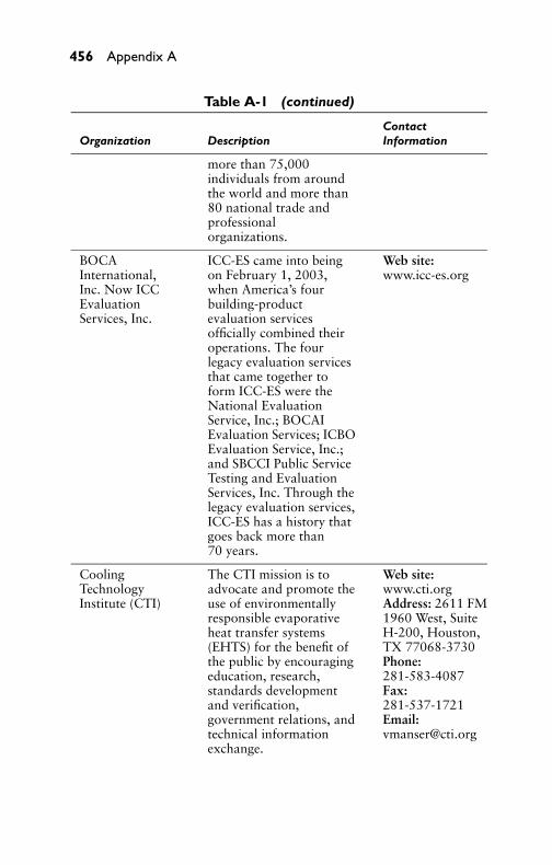
P1: GDZ/FFX P2: GDZ/FFX QC: GDZ/FFX T1: GDZ
GB076-17 GB076-Miller-Sample July 14, 2004 20:15 Char Count= 0
456 Appendix A
Table A-1 (continued)
ContactOrganization Description Information
more than 75,000individuals from aroundthe world and more than80 national trade andprofessionalorganizations.
BOCAInternational,Inc. Now ICCEvaluationServices, Inc.
ICC-ES came into beingon February 1, 2003,when America’s fourbuilding-productevaluation servicesofficially combined theiroperations. The fourlegacy evaluation servicesthat came together toform ICC-ES were theNational EvaluationService, Inc.; BOCAIEvaluation Services; ICBOEvaluation Service, Inc.;and SBCCI Public ServiceTesting and EvaluationServices, Inc. Through thelegacy evaluation services,ICC-ES has a history thatgoes back more than70 years.
Web site:www.icc-es.org
CoolingTechnologyInstitute (CTI)
The CTI mission is toadvocate and promote theuse of environmentallyresponsible evaporativeheat transfer systems(EHTS) for the benefit ofthe public by encouragingeducation, research,standards developmentand verification,government relations, andtechnical informationexchange.
Web site:www.cti.orgAddress: 2611 FM1960 West, SuiteH-200, Houston,TX 77068-3730Phone:281-583-4087Fax:281-537-1721Email:[email protected]

P1: GDZ/FFX P2: GDZ/FFX QC: GDZ/FFX T1: GDZ
GB076-17 GB076-Miller-Sample July 14, 2004 20:15 Char Count= 0
Professional Organizations 457
Table A-1 (continued)
ContactOrganization Description Information
Federation ofEuropeanHeating andAir-ConditioningAssociations
In was in the early 1960sthat the idea of some formof cooperation betweentechnical associations in thefield of heating, ventilatingand air-conditioning wouldbe extremely useful wasrecognized by leadingprofessionals who met eachother in internationalmeetings and conferences.On September 27th, 1963representatives of technicalassociations of nineEuropean countries met inthe Hague, TheNetherlands, at theinvitation of the Dutchassociation TWL. Theseassociations were ATIC(Belgium), AICVF (France),VDI TGA (Germany),IHVE (United Kingdom),CARR (Italy), TWL (TheNetherlands), Norsk WS(Norway), SWKI(Switzerland), and SwedishWS (Sweden). Animpressive list of subjectsabout which furthercooperation was essentialwas brought for discussion.Ways of exchangingtechnical knowledge was atthe top of the list, togetherwith the promotion ofEuropean standardizationand regulations, education,and coordination ofcongress and conferences.
Web site:www.rehva.comAddress:Ravenstein 3Brussels, 1000 BEPhone: 1:32-2-514.11.71

P1: GDZ/FFX P2: GDZ/FFX QC: GDZ/FFX T1: GDZ
GB076-17 GB076-Miller-Sample July 14, 2004 20:15 Char Count= 0
458

P1: GDZ/FFX P2: GDZ/FFX QC: GDZ/FFX T1: GDZ
GB076-18 GB076-Miller-Sample July 14, 2004 20:15 Char Count= 0
Glossary
Absolute Humidity—The weight of water vapor per unit volume(grains per cubic foot, or grams per cubic meter).
Absolute Pressure—The sum of gage pressure and atmospheric pres-sure. For example, if the gage pressure is 154 psi, the absolutepressure will be 154 + 14.7, or 168.7 psi.
Absolute Zero—A temperature equal to −459.6◦F or −273◦C. Atthis temperature the volume of an ideal gas maintained at a con-stant pressure becomes zero.
Absorption—The action of a material in extracting one or more sub-stances present in the atmosphere, or a mixture of gases or liquidsaccompanied by physical change, chemical change, or both.
Acceleration—The time rate of change of velocity. It is the derivativeof velocity with respect to time.
Accumulator—A shell placed in a suction line for separating theliquid entrained in the suction gas.
Acrolein—A warning agent often used with methyl chloride to callattention to the escape of refrigerant. The material has a com-pelling, pungent odor and causes irritation of the throat and eyes.Acrolein reacts with sulfur dioxide to form a sludge.
Activated Alumina—A form of aluminum oxide (Al2O3) that ab-sorbs moisture readily and is used as a drying agent.
Adiabatic—Referring to a change in gas conditions where no heatis added or removed except in the form of work.
Adiabatic Process—Any thermodynamic process taking place in aclosed system without the addition or removal of heat.
Adsorbent—A sorbent that changes physically, chemically, or bothduring the sorption process.
Aeration—Exposing a substance or area to air circulation.Agitation—A condition in which a device causes circulation in a
tank containing fluid.Air, Ambient—Generally speaking, the air surrounding an object.Air Changes—A method of expressing the amount of air leakage into
or out of a building or room in terms of the number of buildingvolumes or room volumes exchanged per unit of time.
Air Circulation—Natural or imparted motion of air.
459
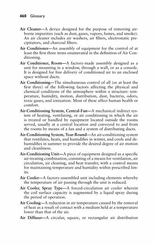
P1: GDZ/FFX P2: GDZ/FFX QC: GDZ/FFX T1: GDZ
GB076-18 GB076-Miller-Sample July 14, 2004 20:15 Char Count= 0
460 Glossary
Air Cleaner—A device designed for the purpose of removing air-borne impurities (such as dust, gases, vapors, fumes, and smoke).An air cleaner includes air washers, air filters, electrostatic pre-cipitators, and charcoal filters.
Air Conditioner—An assembly of equipment for the control of atleast the first three items enumerated in the definition of Air Con-ditioning.
Air Conditioner, Room—A factory-made assembly designed as aunit for mounting in a window, through a wall, or as a console.It is designed for free delivery of conditioned air to an enclosedspace without ducts.
Air Conditioning—The simultaneous control of all (or at least thefirst three) of the following factors affecting the physical andchemical conditions of the atmosphere within a structure: tem-perature, humidity, motion, distribution, dust, bacteria, odors,toxic gases, and ionization. Most of these affect human health orcomfort.
Air-Conditioning System, Central-Fan—A mechanical indirect sys-tem of heating, ventilating, or air conditioning in which the airis treated or handled by equipment located outside the roomsserved, usually at a central location and conveyed to and fromthe rooms by means of a fan and a system of distributing ducts.
Air-Conditioning System, Year-Round—An air-conditioning systemthat ventilates, heats, and humidifies in winter, and cools and de-humidifies in summer to provide the desired degree of air motionand cleanliness.
Air-Conditioning Unit—A piece of equipment designed as a specificair-treating combination, consisting of a means for ventilation, aircirculation, air cleaning, and heat transfer, with a control meansfor maintaining temperature and humidity within prescribed lim-its.
Air Cooler—A factory-assembled unit including elements wherebythe temperature of air passing through the unit is reduced.
Air Cooler, Spray Type—A forced-circulation air cooler whereinthe coil surface capacity is augmented by a liquid spray duringthe period of operation.
Air Cooling—A reduction in air temperature caused by the removalof heat as a result of contact with a medium held at a temperaturelower than that of the air.
Air Diffuser—A circular, square, or rectangular air distribution

P1: GDZ/FFX P2: GDZ/FFX QC: GDZ/FFX T1: GDZ
GB076-18 GB076-Miller-Sample July 14, 2004 20:15 Char Count= 0
Glossary 461
outlet (generally located in the ceiling), composed of deflectingmembers discharging supply air in various directions and planes,arranged to promote mixing of primary air with secondary roomair.
Air, Dry—In psychrometry, air unmixed with or containing no watervapor.
Air Infiltration—The in-leakage of air through cracks, crevices,doors, windows, or other openings caused by wind pressure ortemperature difference.
Air, Recirculated—Return air passed through the conditioner beforebeing again supplied to the conditioned space.
Air, Return—Air returned from conditioned or refrigerated space.Air, Saturated—Moist air in which the partial pressure of the water
vapor is equal to the vapor pressure of the water at the existingtemperature. This occurs when dry air and saturated water vaporcoexist at the same dry-bulb temperature.
Air, Standard—Air with a density of 0.075 lb/ft3 and an absolute vis-cosity of 1.22 × 10 lb mass/ft-sec. This is substantially equivalentto dry air at 70◦F and 29.92 in Hg (barometer).
Air Washer—An enclosure in which air is forced through a spray ofwater to cleanse, humidify, or precool the air.
Ambient Temperature—The temperature of the medium surround-ing an object. In a domestic system having an air-cooled condenser,it is the temperature of the air entering the condenser.
Ammonia Machine—An abbreviation for a compression-refri-gerating machine using ammonia as a refrigerant. Similarly, Freonmachine, sulfur dioxide machine, and so on.
Analyzer—A device used in the high side of an absorption systemfor increasing the concentration of vapor entering the rectifier orcondenser.
Anemometer—An instrument for measuring the velocity of air inmotion.
Antifreeze, Liquid—A substance added to the refrigerant to preventformation of ice crystals at the expansion valve. Antifreeze agentsin general do not prevent corrosion caused by moisture. The useof a liquid should be a temporary measure where large quantitiesof water are involved, unless a drier is used to reduce the moisturecontent. Ice crystals may form when moisture is present below thecorrosion limits, and in such instances, a suitable noncorrosive

P1: GDZ/FFX P2: GDZ/FFX QC: GDZ/FFX T1: GDZ
GB076-18 GB076-Miller-Sample July 14, 2004 20:15 Char Count= 0
462 Glossary
antifreeze liquid is often of value. Materials such as alcohol arecorrosive and, if used, should be allowed to remain in the machinefor a limited time only.
Atmospheric Condenser—A condenser operated with water that isexposed to the atmosphere.
Atmospheric Pressure—The pressure exerted by the atmosphere inall directions as indicated by a barometer. Standard atmosphericpressure is considered to be 14.695 pounds per square inch (psi),which is equivalent to 29.92 inches of mercury (in Hg).
Atomize—To reduce to a fine spray.Automatic Air Conditioning—An air-conditioning system that reg-
ulates itself to maintain a definite set of conditions by means ofautomatic controls and valves usually responsive to temperatureor pressure.
Automatic Expansion Valve—A pressure-actuated device that regu-lates the flow of refrigerant from the liquid line into the evaporatorto maintain a constant evaporator pressure.
Baffle—A partition used to divert the flow of air or a fluid.Balanced Pressure—The same pressure inside a system or container
that exists outside the system or container.Barometer—An instrument for measuring atmospheric pressure in
inches of mercury.Blast Heater—A set of heat-transfer coils or sections used to heat
air that is drawn or forced through it by a fan.Bleeder—A pipe sometimes attached to a condenser to lead off liquid
refrigerant parallel to the main flow.Boiler—A closed vessel in which liquid is heated or vaporized.Boiler Horsepower—The equivalent evaporation of 34.5 pounds of
water per hour from and at 212◦F, which is equal to a heat outputof 970.3 × 34.5 = 33,475 Btu.
Boiling Point—The temperature at which a liquid is vaporized uponthe addition of heat, dependent on the refrigerant and the absolutepressure at the surface of the liquid and vapor.
Bore—The inside diameter of a cylinder.
Brine—Any liquid cooled by a refrigerant and used for transmissionof heat without a change in its state.
Brine System—A system whereby brine cooled by a refrigeratingsystem is circulated through pipes to the point where the refriger-ation is needed.

P1: GDZ/FFX P2: GDZ/FFX QC: GDZ/FFX T1: GDZ
GB076-18 GB076-Miller-Sample July 14, 2004 20:15 Char Count= 0
Glossary 463
British Thermal Unit (Btu)—The amount of heat required to raisethe temperature of one pound of water 1◦F. It is also the measureof the amount of heat removed in cooling one pound of water 1◦Fand is so used as a measure of refrigerating effect.
Butane—A hydrocarbon, flammable refrigerant used to a limitedextent in small units.
Calcium Chloride—A chemical having the formula CaCl2, which, ingranular form, is used as a drier. This material is soluble in water,and in the presence of large quantities of moisture may dissolveand plug up the drier unit or even pass into the system beyondthe drier.
Calcium Sulfate—A solid chemical of the formula CaSO4, whichmay be used as a drying agent.
Calibration—The process of dividing and numbering the scale ofan instrument. Also, correcting and determining the error of anexisting scale.
Calorie—Heat required to raise the temperature of 1 gram of water1◦C (actually, from 4◦C to 5◦C). Mean calorie = 0.01 part of theheat required to raise 1 gram of water from 1◦C to 100◦C.
Capacity, Refrigerating—The ability of a refrigerating system, orpart thereof, to remove heat. Expressed as a rate of heat removal,it is usually measured in Btu/hr or tons/24 hr.
Capacity Reducer—In a compressor, a device, such as a clearancepocket, movable cylinder head, or suction bypass, by which com-pressor capacity can be adjusted without otherwise changing theoperating conditions.
Capillarity—The action by which the surface of a liquid in contactwith a solid (as in a slender tube) is raised or lowered.
Capillary Tube—In refrigeration practice, a tube of small internaldiameter used as a liquid refrigerant-flow control or expansiondevice between high and low sides. Also used to transmit pres-sure from the sensitive bulb of some temperature controls to theoperating element.
Carbon Dioxide Ice—Compressed solid CO2. Dry ice.Celsius—A thermometric system in which the freezing point of water
is called 0◦C and its boiling point 100◦C at normal pressure.Centrifugal Compressor—A compressor employing centrifugal
force for compression.Centrifuge—A device for separating liquids of different densities by
centrifugal action.

P1: GDZ/FFX P2: GDZ/FFX QC: GDZ/FFX T1: GDZ
GB076-18 GB076-Miller-Sample July 14, 2004 20:15 Char Count= 0
464 Glossary
Change of Air—Introduction of new, cleansed, or recirculated air toa conditioned space, measured by the number of complete changesper unit of time.
Change of State—A change from one state to another, as from aliquid to a solid, from a liquid to a gas, and so on.
Charge—The amount of refrigerant in a system.Chimney Effect—The tendency of air or gas in a duct or other verti-
cal passage to rise when heated because of its lower density com-pared with that of the surrounding air or gas. In buildings, thetendency toward displacement, caused by the difference in tem-perature, of internal heated air by unheated outside air becauseof the difference in density of outside and inside air.
Clearance—Space in a cylinder not occupied by a piston at the endof the compression stroke or volume of gas remaining in a cylinderat the same point. Measured in percentage of piston displacement.
Coefficient of Expansion—The fractional increase in length or vol-ume of a material per degree rise in temperature.
Coefficient of Performance (Heat Pump)—Ratio of heating effectproduced to the energy supplied, each expressed in the same ther-mal units.
Coil—Any heating or cooling element made of pipe or tubing con-nected in series.
Cold Storage—A trade or process of preserving perishables on alarge scale by refrigeration.
Comfort Chart—A chart showing effective temperatures with dry-bulb temperatures and humidity (and sometimes air motion) bywhich the effects of various air conditions on human comfortmaybe compared.
Compression System—A refrigerating system in which the pressure-imposing element is mechanically operated.
Compressor—That part of a mechanical refrigerating system thatreceives the refrigerant vapor at low pressure and compresses itinto a smaller volume at higher pressure.
Compressor, Centrifugal—A nonpositive displacement compressorthat depends on centrifugal effect (at least in part) for pressure rise.
Compressor, Open-Type—A compressor with a shaft or other mov-ing part, extending through a casing, to be driven by an out-side source of power, thus requiring a stuffing box, shaft seals, orequivalent rubbing contact between a fixed and moving part.

P1: GDZ/FFX P2: GDZ/FFX QC: GDZ/FFX T1: GDZ
GB076-18 GB076-Miller-Sample July 14, 2004 20:15 Char Count= 0
Glossary 465
Compressor, Reciprocating—A positive displacement compressorwith a piston or pistons moving in a straight line, but alternatelyin opposite directions.
Compressor, Rotary—One in which compression is attained in acylinder by rotation of a positive displacement member.
Compressor Booster—A compressor for very low pressures, usuallydischarging into the suction line of another compressor.
Condenser—A heat-transfer device that receives high-pressure va-por at temperatures above that of the cooling medium (such asair or water) to which the condenser passes latent heat from therefrigerant, causing the refrigerant vapor to liquefy.
Condensing—The process of giving up latent heat of vaporizationto liquefy a vapor.
Condensing Unit—A specific refrigerating machine combination fora given refrigerant, consisting of one or more power-driven com-pressors, condensers, liquid receivers (when required), and theregularly furnished accessories.
Condensing Unit, Sealed—A mechanical condensing unit in whichthe compressor and compressor motor are enclosed in the samehousing, with no external shaft or shaft seal, the compressor mo-tor operating in the refrigerant atmosphere.
Conduction, Thermal—Passage of heat from one point to anotherby transmission of molecular energy from particle to particlethrough a conductor.
Conductivity, Thermal—The ability of a material to pass heat fromone point to another, generally expressed in terms of Btu per hourper square foot of material per inch of thickness per degree tem-perature difference.
Conductor, Electrical—A material that will pass an electric currentas part of an electrical system.
Connecting Rod—A device connecting the piston to a crank andused to change rotating motion into reciprocating motion, or viceversa (as from a rotating crankshaft to a reciprocating piston).
Constant-Pressure Valve—A valve of the throttling type, respon-sive to pressure, located in the suction line of an evaporator tomaintain a desired constant pressure in the evaporator higher thanthe main suction line pressure.
Constant-Temperature Valve—A valve of the throttling type, re-sponsive to the temperature of a thermostatic bulb. This valveis located in the suction line of an evaporator to reduce the

P1: GDZ/FFX P2: GDZ/FFX QC: GDZ/FFX T1: GDZ
GB076-18 GB076-Miller-Sample July 14, 2004 20:15 Char Count= 0
466 Glossary
refrigerating effect on the coil to just maintain a desired mini-mum temperature.
Control—Any device for regulation of a system or component innormal operation (manual or automatic). If automatic, the impli-cation is that it is responsive to changes of temperature, pressure,or any other property whose magnitude is to be regulated.
Control, High-Pressure—A pressure-responsive device (usually anelectric switch) actuated directly by the refrigerant-vapor pressureon the high side of a refrigerating system (usually compressor-headpressure).
Control, Low-Pressure—An electric switch, responsive to pressure,connected into the low-pressure part of a refrigerating system(usually closes at high pressure and opens at low pressure).
Control, Temperature—An electric switch or relay that is responsiveto the temperature change of a thermostatic bulb or element.
Convection—The circulatory motion that occurs in a fluid at anonuniform temperature because of the variation of its densityand the action of gravity.
Convection, Forced—Convection resulting from forced circulationof a fluid (as by a fan, jet, or pump).
Cooling Tower, Water—An enclosed device for making use of thecooling effect of vaporizing water.
Cooling Unit—A specific air-treating combination consisting of ameans for air circulation and cooling within prescribed tempera-ture limits.
Cooling Water—Water used for condensation of refrigerant. Con-denser water.
Copper Plating—Formation of a film of copper (usually on com-pressor walls, pistons, or discharge valves), caused by moisture ina methyl chloride system.
Corrosive—Having a chemically destructive effect on metals (occa-sionally on other materials).
Counter Flow—In the heat exchange between two fluids, the op-posite direction of flow, the coldest portion of one meeting thecoldest portion of the other.
Critical Pressure—The vapor pressure corresponding to the criticaltemperature.
Critical Temperature—The temperature above which a vapor can-not be liquefied, regardless of pressure.

P1: GDZ/FFX P2: GDZ/FFX QC: GDZ/FFX T1: GDZ
GB076-18 GB076-Miller-Sample July 14, 2004 20:15 Char Count= 0
Glossary 467
Critical Velocity—The velocity above which fluid flow is turbulent.Crohydrate—An eutectic brine mixture of water and any salt mixed
in proportions to give the lowest freezing temperature.Cut-In—The temperature or pressure at which a control device sig-
nals a piece of equipment to operate.Cycle—A complete course of operation of working fluid back to a
starting point measured in thermodynamic terms. Also used ingeneral for any repeated process in any system.
Cycle, Defrosting—The portion of a refrigeration operation thatpermits the cooling unit to defrost.
Cycle, Refrigeration—A complete course of operation of a refriger-ant back to the starting point measured in thermodynamic terms.Also used in general for any repeated process for any system.
Dalton’s Law of Partial Pressure—Each constituent of a mixture ofgases behaves thermodynamically as if it alone occupied the space.The sum of the individual pressures of the constituents equals thetotal pressure of the mixture.
Defrosting—Removal of accumulated ice from the cooling unit.Degree Day—A unit based on temperature difference and time
used to specify the nominal heating load in winter. For one daythere exist as many degree days as there are degrees Fahren-heit difference in temperature between the average outside airtemperature, taken over a 24-hour period, and a temperature of65◦F.
Dehumidifier—An air cooler used for lowering the moisture contentof the air passing through it. An absorption or adsorption devicefor removing moisture from the air.
Dehumidify—To remove water vapor from the atmosphere. To re-move water or liquid from stored goods.
Dehydrator—A device used to remove moisture from the refrigerant.Density—The mass or weight per unit of volume.Dew Point, Air—The temperature at which a specified sample of air
(with no moisture added or removed) is completely saturated. Thetemperature at which the air, on being cooled, gives up moistureor dew.
Differential (of a Control)—The difference between the cut-in andcutout temperature or pressure.
Direct Connected—Driver and driven, as motor and compressor,positively connected in line to operate at the same speed.
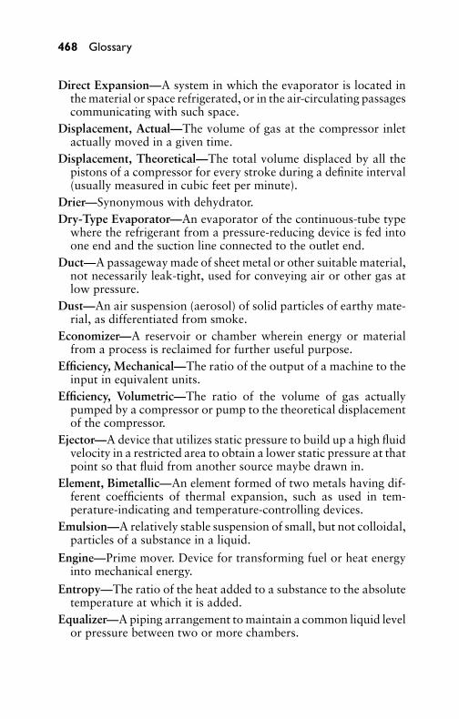
P1: GDZ/FFX P2: GDZ/FFX QC: GDZ/FFX T1: GDZ
GB076-18 GB076-Miller-Sample July 14, 2004 20:15 Char Count= 0
468 Glossary
Direct Expansion—A system in which the evaporator is located inthe material or space refrigerated, or in the air-circulating passagescommunicating with such space.
Displacement, Actual—The volume of gas at the compressor inletactually moved in a given time.
Displacement, Theoretical—The total volume displaced by all thepistons of a compressor for every stroke during a definite interval(usually measured in cubic feet per minute).
Drier—Synonymous with dehydrator.Dry-Type Evaporator—An evaporator of the continuous-tube type
where the refrigerant from a pressure-reducing device is fed intoone end and the suction line connected to the outlet end.
Duct—A passageway made of sheet metal or other suitable material,not necessarily leak-tight, used for conveying air or other gas atlow pressure.
Dust—An air suspension (aerosol) of solid particles of earthy mate-rial, as differentiated from smoke.
Economizer—A reservoir or chamber wherein energy or materialfrom a process is reclaimed for further useful purpose.
Efficiency, Mechanical—The ratio of the output of a machine to theinput in equivalent units.
Efficiency, Volumetric—The ratio of the volume of gas actuallypumped by a compressor or pump to the theoretical displacementof the compressor.
Ejector—A device that utilizes static pressure to build up a high fluidvelocity in a restricted area to obtain a lower static pressure at thatpoint so that fluid from another source maybe drawn in.
Element, Bimetallic—An element formed of two metals having dif-ferent coefficients of thermal expansion, such as used in tem-perature-indicating and temperature-controlling devices.
Emulsion—A relatively stable suspension of small, but not colloidal,particles of a substance in a liquid.
Engine—Prime mover. Device for transforming fuel or heat energyinto mechanical energy.
Entropy—The ratio of the heat added to a substance to the absolutetemperature at which it is added.
Equalizer—A piping arrangement to maintain a common liquid levelor pressure between two or more chambers.
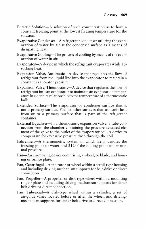
P1: GDZ/FFX P2: GDZ/FFX QC: GDZ/FFX T1: GDZ
GB076-18 GB076-Miller-Sample July 14, 2004 20:15 Char Count= 0
Glossary 469
Eutectic Solution—A solution of such concentration as to have aconstant freezing point at the lowest freezing temperature for thesolution.
Evaporative Condenser—A refrigerant condenser utilizing the evap-oration of water by air at the condenser surface as a means ofdissipating heat.
Evaporative Cooling—The process of cooling by means of the evap-oration of water in air.
Evaporator—A device in which the refrigerant evaporates while ab-sorbing heat.
Expansion Valve, Automatic—A device that regulates the flow ofrefrigerant from the liquid line into the evaporator to maintain aconstant evaporator pressure.
Expansion Valve, Thermostatic—A device that regulates the flow ofrefrigerant into an evaporator to maintain an evaporation temper-ature in a definite relationship to the temperature of a thermostaticbulb.
Extended Surface—The evaporator or condenser surface that isnot a primary surface. Fins or other surfaces that transmit heatfrom or to a primary surface that is part of the refrigerantcontainer.
External Equalizer—In a thermostatic expansion valve, a tube con-nection from the chamber containing the pressure-actuated ele-ment of the valve to the outlet of the evaporator coil. A device tocompensate for excessive pressure drop through the coil.
Fahrenheit—A thermometric system in which 32◦F denotes thefreezing point of water and 212◦F the boiling point under nor-mal pressure.
Fan—An air-moving device comprising a wheel, or blade, and hous-ing or orifice plate.
Fan, Centrifugal—A fan rotor or wheel within a scroll-type housingand including driving-mechanism supports for belt-drive or directconnection.
Fan, Propeller—A propeller or disk-type wheel within a mountingring or plate and including driving-mechanism supports for eitherbelt-drive or direct connection.
Fan, Tubeaxial—A disk-type wheel within a cylinder, a set ofair-guide vanes located before or after the wheel, and driving-mechanism supports for either belt-drive or direct connection.

P1: GDZ/FFX P2: GDZ/FFX QC: GDZ/FFX T1: GDZ
GB076-18 GB076-Miller-Sample July 14, 2004 20:15 Char Count= 0
470 Glossary
Filter—A device to remove solid material from a fluid by a strainingaction.
Flammability—The ability of a material to burn.Flare Fitting—A type of connector for soft tubing that involves the
flaring of the tube to provide a mechanical seal.Flash Gas—The gas resulting from the instantaneous evaporation
of the refrigerant in a pressure-reducing device to cool the re-frigerant to the evaporation temperature obtained at the reducedpressure.
Float Valve—Valve actuated by a float immersed in a liquid con-tainer.
Flooded System—A system in which the refrigerant enters into aheader from a pressure-reducing valve and the evaporator main-tains a liquid level. As opposed to a dry evaporator.
Fluid—A gas or liquid.Foaming—Formation of a foam or froth of oil refrigerant because
of rapid boiling out of the refrigerant dissolved in the oil when thepressure is suddenly reduced. This occurs when the compressoroperates. If large quantities of refrigerant have been dissolved,large quantities of oil may boil out and be carried through therefrigerant lines.
Freeze-Up—Failure of a refrigeration unit to operate normally be-cause of the formation of ice at the expansion valve. The valvemay be frozen closed or open, causing improper refrigeration ineither case.
Freezing Point—The temperature at which a liquid will solidify uponthe removal of heat.
Freon-12—The common name for dichlorodifluoromethane(CCl2F2).
Frostback—The flooding of liquid from an evaporator into the suc-tion line, accompanied by frost formation on the suction line inmost cases.
Furnace—That part of a boiler or warm-up heating plant wherecombustion takes place. Also, a complete heating unit for trans-ferring heat from fuel being burned to the air supplied to a heatingsystem.
Fusible Plug—A safety plug used in vessels containing refrigerant.The plug is designed to melt at high temperatures (usually about165◦F) to prevent excessive pressure from bursting the vessel.
P1: GDZ/FFX P2: GDZ/FFX QC: GDZ/FFX T1: GDZ
GB076-18 GB076-Miller-Sample July 14, 2004 20:15 Char Count= 0
Glossary 471
Gage—An instrument used for measuring various pressures or liquidlevels.
Gas—The vapor state of a material.Generator—A basic component of any absorption-refrigeration sys-
tem.Gravity, Specific—The density of a standard material usually com-
pared to that of water or air.Grille—A perforated or louvered covering for an air passage. It is
usually installed in a sidewall, ceiling, or floor.Halide Torch—A leak tester generally using alcohol and burning
with a blue flame. When the sampling tube draws in a halocarbonrefrigerant vapor, the color of flame changes to bright green. Gasgiven off by the burning halocarbon is phosgene, a deadly gas usedin World War I in Europe against Allied troops (can be deadly ifbreathed in a closed or confined area).
Heat—Basic form of energy that may be partially converted intoother forms and into which all other forms may be entirely con-verted.
Heat of Fusion—Latent heat involved in changing between the solidand the liquid states.
Heat, Sensible—Heat that is associated with a change in tempera-ture; specific heat exchange of temperature, in contrast to a heatinterchange in which a change of state (latent heat) occurs.
Heat, Specific—The ratio of the quantity of heat required to raise thetemperature of a given mass of any substance 1◦ to the quantityrequired to raise the temperature of an equal mass of a standardsubstance (usually water at 59◦F) 1◦.
Heat of Vaporization—Latent heat involved in the change betweenliquid and vapor states.
Heat Pump—A refrigerating system employed to transfer heat intoa space or substance. The condenser provides the heat, while theevaporator is arranged to pick up heat from air, water, and so on.By shifting the flow of the refrigerant, a heat-pump system mayalso be used to cool the space.
Heating System—Any of several heating methods usually termedaccording to the method used in its generation, such as steamheating, warm-air heating, and so on.
Heating System, Electric—Heating produced by a rise of temper-ature, the increase caused by the passage of an electric current

P1: GDZ/FFX P2: GDZ/FFX QC: GDZ/FFX T1: GDZ
GB076-18 GB076-Miller-Sample July 14, 2004 20:15 Char Count= 0
472 Glossary
through a conductor with the conductor having a high resis-tance to the current flow. Residence electric-heating systems gen-erally consist of one or several resistance units installed in aframe or casing, the degree of heating being thermostatically con-trolled.
Heating System, Steam—A heating system in which heat is trans-ferred from a boiler or other source to the heating units by steamat, above, or below atmospheric pressure.
Heating System, Vacuum—A two-pipe steam-heating systemequipped with the necessary accessory apparatus to permit op-erating the system below atmospheric pressure.
Heating System, Warm-Air—A warm-air heating plant consistingof a heating unit (fuel-burning furnace) enclosed in a casing fromwhich the heated air is distributed to various rooms of the buildingthrough ducts.
Heremetically Sealed Unit—A refrigerating unit containing the mo-tor and compressor in a sealed container.
High-Pressure Cutout—A control device connected into the high-pressure part of a refrigerating system to stop the machine whenthe pressure becomes excessive.
High Side—That part of the refrigerating system containing thehigh-pressure refrigerant. Also the term used to refer to the con-densing unit, consisting of the motor, compressor, condenser, andreceiver mounted on a single base.
High-Side Float Valve—A float valve that floats in high-pressureliquid. Opens on an increase in liquid level.
Hold Over—In an evaporator, the ability to stay cold after heatremoval from the evaporator stops.
Horsepower—A unit of power. Work done at the rate of 33,000foot-pounds per minute, or 550 foot-pounds per second. Onehorsepower is equal to 746 watts in electrical terms.
Humidifier—A device to add moisture to the air.Humidify—To add water vapor to the atmosphere, or to add water
vapor or moisture to any material.Humidistat—A control device actuated by changes in humidity and
used for automatic control of relative humidity.Humidity, Absolute—The definite amount of water contained in a
definite quantity of air (usually measured in grains of water perpound or per cubic foot of air).
P1: GDZ/FFX P2: GDZ/FFX QC: GDZ/FFX T1: GDZ
GB076-18 GB076-Miller-Sample July 14, 2004 20:15 Char Count= 0
Glossary 473
Humidity, Relative—The ratio of the water-vapor pressure of aircompared to the vapor pressure it would have if saturated at itsdry-bulb temperature. Very near the ratio of the amount of mois-ture contained in air compared to what it could hold at the existingtemperature.
Humidity, Specific—The weight of vapor associated with one poundof dry air; also termed humidity ratio.
Hydrocarbons—A series of chemicals of similar chemical nature,ranging from methane (the main constituent of natural gas)through butane, octane, and so on, to heavy lubricating oils. Allare more or less flammable. Butane and isobutane have been usedto a limited extent as refrigerants.
Hydrolysis—Reaction of a material (such as Freon-12 or methylchloride) with water. Acid materials in general are formed.
Hydrostatic Pressure—The pressure caused by liquid in a containerthat contains no gas space.
Hygroscope—See Humidistat.Ice-Melting Equivalent—The amount of heat (144 Btu) absorbed by
one pound of ice at 32◦F in liquefying to water at 32◦F.Indirect Cooling System—See Brine System.Infiltration—The leakage of air into a building or space.Insulation—A material of low heat conductivity.Irritant Refrigerant—Any refrigerant that has an irritating effect on
the eyes, nose, throat, or lungs.Isobutane—A hydrocarbon refrigerant used to a limited extent. It is
flammable.Kilowatt—Unit of electrical power equal to 1000 watts, or 1.34
horsepower, approximately.Lag of Temperature Control—The delay in action of a temperature-
responsive element caused by the time required for the tempera-ture of the element to reach the surrounding temperature.
Latent Heat—The quantity of heat that may be added to a substanceduring a change of state without causing a temperature change.
Latent Heat of Evaporation—The quantity of heat required tochange 1 pound of liquid into a vapor with no change in tem-perature. Reversible.
Leak Detector—A device used to detect refrigerant leaks in a refrig-erating system.

P1: GDZ/FFX P2: GDZ/FFX QC: GDZ/FFX T1: GDZ
GB076-18 GB076-Miller-Sample July 14, 2004 20:15 Char Count= 0
474 Glossary
Liquid—The state of a material in which its top surface in a ves-sel will become horizontal. Distinguished from solid or vaporforms.
Liquid Line—The tube or pipe that carries the refrigerant liquid fromthe condenser or receiver of a refrigerating system to a pressure-reducing device.
Liquid Receiver—That part of the condensing unit that stores theliquid refrigerant.
Load—The required rate of heat removal.Low-Pressure Control—An electric switch and pressure-responsive
element connected into the suction side of a refrigerating unit tocontrol the operation of the system.
Low Side—That part of a refrigerating system that normally oper-ates under low pressure, as opposed to the high side. Used also torefer to the evaporator.
Low-Side Float—A valve operated by the low-pressure liquid, whichopens at a low level and closes at a high level.
Main—A pipe or duct for distributing to or collecting conditionedair from various branches.
Manometer—A U-shaped liquid-filled tube for measuring pressuredifferences.
Mechanical Efficiency—The ratio of work done by a machine to thework done on it or energy used by it.
Mechanical Equivalent of Heat—An energy-conversion ratio of778.18 foot-pounds = 1 Btu.
Methyl Chloride—A refrigerant having the chemical formulaCH3Cl.
Micron (µ)—A unit of length; the thousandth part of one millimeteror the millionth part of a meter.
Mollier Chart—A graphical representation of thermal properties offluids, with total heat and entropy as coordinates.
Motor—A device for transforming electrical energy into mechanicalenergy.
Motor Capacitor—A device designed to improve the starting abilityof single-phase induction motors.
Noncondensables—Foreign gases mixed with a refrigerant thatcannot be condensed into liquid form at the temperatures andpressures at which the refrigerant condenses.
P1: GDZ/FFX P2: GDZ/FFX QC: GDZ/FFX T1: GDZ
GB076-18 GB076-Miller-Sample July 14, 2004 20:15 Char Count= 0
Glossary 475
Oil Trap—A device to separate oil from the high-pressure vaporfrom the compressor. Usually contains a float valve to return theoil to the compressor crankcase.
Output—Net refrigeration produced by the system.Ozone—The O3 form of oxygen, sometimes used in air condition-
ing or cold-storage rooms to eliminate odors. Can be toxic inconcentrations of 0.5 ppm and over.
Packing—The stuffing around a shaft to prevent fluid leakage be-tween the shaft and parts around the shaft.
Packless Valve—A valve that does not use packing to prevent leaksaround the valve stem. Flexible material is usually used to sealagainst leaks and still permit valve movement.
Performance Factor—The ratio of the heat moved by a refrigeratingsystem to heat equivalent of the energy used. Varies with condi-tions.
Phosphorous Pentoxide—An efficient drier material that becomesgummy reacting with moisture and hence is not used alone as adrying agent.
Pour Point, Oil—The temperature below which the oil surface willnot change when the oil container is tilted.
Power—The rate of doing work measured in horsepower, watts,kilowatts, and so on.
Power Factor, Electrical Devices—The ratio of watts to volt-amperesin an alternating current circuit.
Pressure—The force exerted per unit of area.Pressure Drop—Loss in pressure, as from one end of a refrigerant
line to the other, due to friction, static head, and so on.Pressure Gage—See Gage.
Pressure-Relief Valve—A valve or rupture member designed to re-lieve excessive pressure automatically.
Psychrometric Chart—A chart used to determine the specific vol-ume, heat content, dew point, relative humidity, absolute hu-midity, and wet- and dry-bulb temperatures, knowing any twoindependent items of those mentioned.
Purging—The act of blowing out refrigerant gas from arefrigerant-containing vessel usually for the purpose of removingnoncondensables. Release of the refrigerant into the atmosphereis now illegal.

P1: GDZ/FFX P2: GDZ/FFX QC: GDZ/FFX T1: GDZ
GB076-18 GB076-Miller-Sample July 14, 2004 20:15 Char Count= 0
476 Glossary
Pyrometer—An instrument for the measurement of high tempera-tures.
Quick-connect—A connector used to join precharged systems with-out the need for evacuation.
Radiation—The passage of heat from one object to another withoutwarming the space between. The heat is passed by wave motionsimilar to light.
Refrigerant—The medium of heat transfer in a refrigerating systemthat picks up heat by evaporating at a low temperature and givesup heat by condensing at a higher temperature.
Refrigerating System—A combination of parts in which a refrigerantis circulated for the purpose of extracting heat.
Relative Humidity—The ratio of the water-vapor pressure of aircompared to the vapor pressure it would have if saturated at itsdry-bulb temperature. Very near the ratio of the amount of mois-ture contained in air compared to what it could hold at the existingtemperature.
Relief Valve—A valve designed to open at excessively high pressuresto allow the refrigerant to escape.
Resistance, Electrical—The opposition to electric-current flow, mea-sured in ohms.
Resistance, Thermal—The reciprocal of thermal conductivity.
Room Cooler—A cooling element for a room. In air conditioning,a device for conditioning small volumes of air for comfort.
Rotary Compressor—A compressor in which compression is at-tained in a cylinder by rotation of a semiradial member.
Running Time—Usually indicates percent of time a refrigerant com-pressor operates.
Saturated Vapor—Vapor not superheated but of 100 percent quality(that is, containing no unvaporized liquid).
Schraeder Valve—A valve that permits the flow in one direction ifpressure exceeds a setting and in the other if the pin is depressed.The same type of valve that is used to inflate a car’s tires.
Seal, Shaft—A mechanical system of parts for preventing gas leakagebetween a rotating shaft and a stationary crankcase.
Sealed Unit—See Hermetically Sealed Unit.
Shell and Tube—Pertaining to heat exchangers in which a coil oftubing or pipe is contained in a shell or container. The pipe is
P1: GDZ/FFX P2: GDZ/FFX QC: GDZ/FFX T1: GDZ
GB076-18 GB076-Miller-Sample July 14, 2004 20:15 Char Count= 0
Glossary 477
provided with openings to allow the passage of a fluid through it,while the shell is also provided with an inlet and outlet for a fluidflow.
Silica Gel—A drier material having the formula SiO2.Sludge—A decomposition product formed in a refrigerant caused
by impurities in the oil or moisture. Sludges may be gummy orhard.
Soda Lime—A material used for removing moisture. Not recom-mended for refrigeration use.
Solenoid Valve—A valve opened by a magnetic effect of an electriccurrent through a solenoid coil.
Solid—The state of matter in which a force can be exerted in adownward direction only when not confined (as distinguishedfrom fluids).
Solubility—The ability of one material to enter into solution withanother.
Solution—The homogeneous mixture of two or more materials.Specific Gravity—The weight of a volume of a material compared
to the weight of the same volume of water.Specific Heat—The quantity of heat required to raise the tempera-
ture of a definite mass of a material a definite amount comparedto that required to raise the temperature of the same mass of waterthe same amount. May be expressed as Btu/per pound per degreesFahrenheit.
Specific Volume—The volume of a definite weight of a material.Usually expressed in cubic feet per pound. The reciprocal of den-sity.
Spray Pond—An arrangement for lowering the temperature of waterby evaporative cooling of the water in contact with outside air.The water to be cooled is sprayed by nozzles into the space abovea body of previously cooled water and allowed to fall by gravityinto it.
Steam—Water in the vapor phase.Steam Trap—A device for allowing the passage of condensate, or
air and condensate, and preventing the passage of steam.Subcooled—Cooled below the condensing temperature correspond-
ing to the existing pressure.Sublimation—The change from a solid to a vapor state without an
intermediate liquid state.

P1: GDZ/FFX P2: GDZ/FFX QC: GDZ/FFX T1: GDZ
GB076-18 GB076-Miller-Sample July 14, 2004 20:15 Char Count= 0
478 Glossary
Suction Line—The tube or pipe that carries refrigerant vapor fromthe evaporator to the compressor inlet.
Suction Pressure—Pressure on the suction side of the compressor.Superheat—Increase in temperature above boiling point for a given
pressure. Increase in temperature of suction line gas over the evap-orator.
Superheater—A heat exchanger used on flooded evaporators,wherein hot liquid on its way to enter the evaporator is cooledby supplying heat to dry and superheat the wet vapor leaving theevaporator.
Sweating—Condensation of moisture from the air on surfaces belowthe dew-point temperature.
System—A heating or refrigerating scheme or machine, usually con-fined to those parts in contact with the heating or refrigeratingmedium.
Temperature—Heat level or pressure. The thermal state of a bodywith respect to its ability to pick up heat from or pass heat toanother body.
Thermal Conductivity—The ability of a material to conduct heatfrom one point to another. Indicated in terms of Btu/per hour persquare foot per inches of thickness per degrees Fahrenheit.
Thermistor—An electronic sensor in which resistance is propor-tional to the temperature sensed.
Thermocouple—A device consisting of two electrical conductorshaving two junctions: one at a point whose temperature is to bemeasured and the other at a known temperature. The temper-ature between the two junctions is determined by the materialcharacteristics and the electrical potential setup.
Thermodynamics—The science of the mechanics of heat.
Thermometer—A device for indicating temperature.
Thermostat—A temperature-actuated switch.
Thermostatic Expansion Valve—A device to regulate the flow of re-frigerant into an evaporator to maintain an evaporation tempera-ture in a definite relationship to the temperature of a thermostaticbulb.
Ton of Refrigeration—Refrigeration equivalent to the melting of1 ton of ice per 24 hours (288,000 Btu per day, 12,000 Btu perhour, or 200 Btu per minute).

P1: GDZ/FFX P2: GDZ/FFX QC: GDZ/FFX T1: GDZ
GB076-18 GB076-Miller-Sample July 14, 2004 20:15 Char Count= 0
Glossary 479
Total Heat—The total heat added to a refrigerant above an arbi-trary starting point to bring it to a given set of conditions (usuallyexpressed in Btu/per pound). For example, in a super-heated gas,the combined heat added to the liquid necessary to raise its tem-perature from an arbitrary starting point to the evaporation tem-perature to complete evaporation, and to raise the temperature tothe final temperature where the gas is superheated.
Total Pressure—In fluid flow, the sum of static pressure and velocitypressure.
Turbulent Flow—Fluid flow in which the fluid moves transverselyas well as in the direction of the tube or pipe axis, as opposed tostreamline or viscous flow.
Unit Heater—A direct-heating, factory-made, encased assembly.It includes a heating element, fan, motor, and directionaloutlet.
Unit System—A system that can be removed from the user’s premiseswithout disconnecting refrigerant-containing parts, water connec-tion, or fixed electrical connections.
Unloader—A device in a compressor for equalizing high- and low-side pressures when the compressor stops and for a brief periodafter it starts, to decrease the starting load on the motor.
Vacuum—A pressure below atmospheric, usually measured ininches of mercury below atmospheric pressure.
Valve—In refrigeration, a device for regulation of a liquid, air, orgas.
Vapor—A gas, particularly one near to equilibrium with the liquidphase of the substance, that does not follow the gas laws. Fre-quently, used instead of gas for a refrigerant and, in general, forany gas below the critical temperature.
Viscosity—The property of a fluid to resist flow or change of shape.Water Cooler—Evaporator for cooling water in an indirect refriger-
ating system.Wax—A material that may separate when oil/refrigerant mixtures
are cooled. Wax may plug the expansion valve and reduce heattransfer of the coil.
Wet-Bulb Depression—Difference between dry- and wet-bulb tem-peratures. Used to find relative humidity.
Wet Compression—A system of refrigeration in which some liquidrefrigerant is mixed with vapor entering the compressor to cause
P1: GDZ/FFX P2: GDZ/FFX QC: GDZ/FFX T1: GDZ
GB076-18 GB076-Miller-Sample July 14, 2004 20:15 Char Count= 0
480 Glossary
discharge vapors from the compressor to tend to be saturatedrather than superheated.
Xylene—A flammable solvent, similar to kerosene, used for dissolv-ing or loosening sludges and for cleaning compressors and lines.
Zero, Absolute, of Pressure—The pressure existing in a vessel thatis entirely empty. The lowest possible pressure. Perfect vacuum.
Zero, Absolute, of Temperature—The temperature at which a bodyhas no heat in it (−459.6◦F, or −273.1◦C).
Zone, Comfort (Average)—The range of effective temperature dur-ing which the majority of adults feel comfortable.

P1: GIG
GB076-Ind GB076-Miller-Sample July 14, 2004 20:16 Char Count= 0
Index
Aabsolute humidity, 459, 472absolute pressure, 459absolute zero, 5, 6–7, 459, 480absorption, 459absorption central air-conditioning
system, 331, 338–341, 366and compression system
compared, 338–339, 366cycle of operation, 339–341
acceleration, 459AC motor controls, 413–418accumulator, 459acrolein, 152, 459activated alumina, 459adiabatic, 459adiabatic process, 459adsorbent, 459adsorption-type dehumidifiers,
76–77aeration, 459agitation, 459air
ambient, 459circulation of, 1, 2, 459cleaning and filtering of, 1, 2–3,
61–62, 97. See also airfilters
components of, 1–2, 12conditioning of, 1cooling, 1defined, 1dehumidifying, 1, 15, 27, 73–74,
98, 467dry, 19, 461fresh, requirements for, 57–58heating, 1humidifying, 1, 15, 27, 472impurities, removal of, 2moisture in, 15. See also
humidityrecirculated, 461return, 461saturated, 461standard, 461
volume of, required, 58–59, 90,91
water vapor in, 15airborne diseases, 60air changes, 459air circulation, 1, 2, 459air cleaner, 2, 460air-cleaning equipment, 97
classifications of, 61–62air conditioner(s)
compressors for, 171–172,176–215
condensers, 173, 214, 217–239cycle of operation, 214–215defined, 460economic considerations and,
29efficiency mandates for, 189electrical components of, 171,
172evaporators for, 173, 241–271expansion valves, 174heat loss in selection of, 29, 51mechanical components of,
171–174, 214nonportable, 357–361receivers, 173, 214refrigerant controls, 174, 214,
245–251refrigerants, selection of,
175–176refrigeration cycle, 174–175room. See room air conditionerssize of, calculating, 11, 29, 51suspended-type, 361–363troubleshooting, 140–143,
207–214, 363–366,444–450
air conditioningair circulation and, 2air-mass modification,
adjustments for, 326air moisture and, 15atmospheric conditions affected
by, 1, 12, 15
481

P1: GIG
GB076-Ind GB076-Miller-Sample July 14, 2004 20:16 Char Count= 0
482 Index
air conditioning (continued)automatic, 290, 308, 462automobile, 369–396building materials and choice of,
30–51central-fan system, 460controls, 289–309defined, 1, 460elevation, adjustments for, 326energy consumption
considerations, 328indoor design conditions,
311–312maintenance of, 431–451motors and motor controls,
399–428outdoor design conditions,
312–325, 328properties underlying, 3–7unit, defined, 460vegetation, adjustments for, 326water-cooled, winter shutdown
of, 204–205year-round central, 331–366,
460Air-Conditioning Contractors of
America (ACCA), 453air-cooled condenser(s), 217–218,
238, 279–280head-pressure controls, 230–232placement of, 217pressure stabilization in,
230–232types of, 217
air cooler/cooling, 460air diffuser, 460–461air ducts
air velocities, 60, 80, 81console air conditioners,
installing, 119–122defined, 468design of, 77–79heat gains in, 79–80location of, 60resistance in, 59, 85–88, 97shape of, 85–86sizing, 80–85, 97
air-duct ventilation systems, 77–88air velocities, recommended, 80,
81duct design, 77–79heat gains in ducts, 79–80resistance losses in, 85–88, 97sizing calculations, 80–85suitable duct velocities, 80
air filters, 60–69, 97absorbers, 63central air-conditioning, 335classification of, 61–62dry, 2, 12, 62–63, 97dry plate, 62electronic, 12flushing-type, 65function of, 60immersion-type, 64–65inspection of, 137installation of, 68–69manually cleaned, 64need for, 61purpose of, 12requirements for, 68for suspended-type air
conditioners, 383wet (viscous), 2, 64–67, 97wet replacement-type, 64
air filtration, 60–61, 97air humidification, 69air infiltration, 19, 27, 29, 53,
461, 473air leakage, 53air-mass modification, 326air moisture
grains of moisture, 16, 27and rate of evaporation, 16specific volume, 17See also humidity
Air Movement and ControlAssociation (AMCA)International, Inc., 453
air-movement factor, 17air-operated humidifiers, 72–73air purifiers, 66–67air-supply system, central air
conditioning systems, 332

P1: GIG
GB076-Ind GB076-Miller-Sample July 14, 2004 20:16 Char Count= 0
Index 483
air volume required, 58–59, 90, 91air washer(s), 70, 98, 335, 461air washing, 2–3alcohol thermometer, 17algae growth, treating, 276, 287altitude, 1, 19, 27, 326ambient temperature, 273, 461American Institute of Architects
(AIA), 453American National Standards
Institute (ANSI), 454American Society of Heating and
Ventilating Engineers, 68, 93American Society of Heating,
Refrigeration, and AirConditioning Engineers(ASHRAE), 311
ammonia, 153, 166first aid for exposure to, 168
ammonia machine, 461analyzer, 461anemometer, 461antifreeze, 204, 461–462artificial cold, properties
underlying the production of,3–7
atmospheric condenser, 462atmospheric conditions, 1, 12
measuring. See psychrometryatmospheric pressure, 8–9, 10, 13
defined, 462standard at sea level, 9, 13, 19,
27atomize, 462attic fans, 94
installation of, 95–97automatic air conditioning, 290,
308, 462automatic expansion valve(s),
139, 301defined, 462function of, 174, 300, 308–309
automatic viscous filters, 64–67automobile air-conditioning,
369–396air distribution, 384, 386air output, 385–386
components of, 369, 370,375–384, 395
compressor, 372, 375–376, 395compressor clutch, 387, 396compressor malfunction,
386–387condenser, 376, 387, 396controls, 384, 386cooling, malfunctions of, 385evaporator, 380, 388, 396hot-gas bypass-valve control,
371, 373installation of, 389–391, 395magnetic clutch control, 369,
372, 381–382, 395operation of, 373–375receiver-dehydrator, 376–377refrigerant-flow control,
369–371, 374, 395refrigerant lines, 388refrigerant used in, 162, 373,
388service and maintenance,
384–389sight glass, use of for diagnosis,
389solenoid control, 380–381suction pressures, checking, 386suction-throttle valve, 382–384,
388, 396temperature controls, 369, 395thermostat, 369thermostatic expansion valve,
377–380, 387–388, 396troubleshooting, 392–394
Bback pressure, checking, 434bacteria, 1, 12, 60baffle, 462balanced pressure, 462barometer, 10
defined, 8, 13, 462using, 8–9
barometric pressure, 9, 10, 27belt drives, motors, 215, 422blast coils, 244

P1: GIG
GB076-Ind GB076-Miller-Sample July 14, 2004 20:16 Char Count= 0
484 Index
blast heater, 462bleeder, 462bleeder shell-and-tube condenser,
219BOCA International, Inc. 456body heat, 19, 27boiler, 462boiler horsepower, 462boiling point, 7, 15, 27
defined, 462Freons, 156–157refrigerants, 147, 148, 152, 154,
245bore, 462boxed-in fans, 95Boyle and Charles, combined law
of, 6Boyle’s law, 6brine, 462brine refrigeration systems,
154–155, 241, 242, 462British thermal unit (Btu), 4, 10,
27, 463building materials, effect of on
air-conditioning systems,30–51
butane, 463
Ccalcium chloride (CaCl2),
154–155, 463calcium sulfate, 463calibration, 463calorie, 463capacitor motors, 91–92, 133–134capacitors, 91, 411–412, 474capacitor-start motors, 407–408,
428capacity
compressor, 205cooling, 103evaporator, 251, 252, 269, 271refrigerant controls, 251refrigerant cylinders, 167–168refrigeration, 10–12, 463room air conditioners, 103–104ventilator, 56
capacity reducer, 463capillarity, 463capillary tube(s), 305, 309, 463carbon dioxide, 1, 12, 154, 166carbon dioxide ice, 463carbon monoxide, 1, 2, 12carbon tetrachloride (CCI4), 214Carnot cycle, 163casement windows, installing air
conditioners in, 111–115Celsius scale
converting to Fahrenheit, 7–8defined, 7, 463
central air-conditioning. Seeyear-round central airconditioning
centrifugal-and-turbine fans, 334,335
centrifugal compressor, 171,192–193, 195–198, 215
component parts of, 195construction features, 195–196defined, 192, 463, 464lubrication system, 196–198uses of, 192–193, 195
centrifugal fans, 89, 95, 98, 469centrifuge, 463change of air, 464change of state, 464charge, 464Charles, law of, 5check valves, 267–269, 271chilling units, 247–249chimney effect, 464chlorofluorocarbon compounds
(CFCs), 147–148.ban on use of, 148See also Freon family of
refrigerantschoke coil, 127circulating fans, 94class-A–D motors, 400–401class 1–3 refrigerants, 150cleaning
air, 1, 2–3, 61–62, 97dry filters, 63compressors, 214

P1: GIG
GB076-Ind GB076-Miller-Sample July 14, 2004 20:16 Char Count= 0
Index 485
condensers, 232, 233–235, 239inhibitor powder, 234
clearance, 464climatic conditions
and individual comfort levels,25, 26–27
in U.S., by state, 314–325clouds, 15coefficient of expansion, 464coefficient of heat transfer, 251,
270coefficient of performance
heat pump, 464refrigerants, 163–164
coil(s), 244, 464. See also coolingcoils; heating coils
coiled evaporator, 241, 243–244cold storage, 464combination gages, 437combined law of Boyle and
Charles, 6comfort
air moisture and, 15, 27atmospheric conditions affecting,
1designing for, 311–312, 326–328climatic conditions and, 25,
314–325recommended indoor
temperatures for, 25–27temperature-humidity index and,
18comfort chart, 25–27, 464
optimum comfort line, 26–27compound gages, 10, 12, 436compound-wound motors, 399,
425compression process, 175, 215compression system, 464compressor(s)
amperage, 139automobile air-conditioning,
375–376, 395booster, 465capacity, 205centrifugal, 171, 192–193,
195–198, 215, 463, 464
classification of, 171–172,176–177, 214, 215
cleaning, 214closed-type, 178clutch, 387, 396components of, 172, 214connecting rods, 181, 182, 465cooling, 184crankshafts, 181–183defined, 464flowback protection, 199–200foundation, 198function of, 171, 176, 214hermetic, 178, 179, 184, 215,
472installation and maintenance of,
198–205knocks, 202lubrication, 184malfunction of in automobile
air-conditioning, 386–387mechanical efficiency, 205motor and belts, installation and
maintenance of, 135–137,199
motor controls, 402–421, 428open-type, 178, 464operation of, 214–215performance, 205pistons and piston rings,
178–181reciprocating, 125, 153, 171,
177–184, 215, 465removal of, 202–203replacement of, 203room air conditioner, 101, 103,
124–125rotary, 153, 171, 184–189, 215,
465scroll, 189–192, 193shaft-seal, 183–184, 201sizes, 171, 214startup, 203stuck-up, 202testing, 134–135, 205–106tight, 202troubleshooting, 207–213
P1: GIG
GB076-Ind GB076-Miller-Sample July 14, 2004 20:16 Char Count= 0
486 Index
compressor(s) (continued)valves, 178, 200–201, 435–436,
444volumetric efficiency, 205winter shutdown of, 204–205
compressor clutch, 387, 396compressor valves, 178, 200–201
checking, 435–436, 444condenser(s)
air-cooled, 173, 217–218, 238,279–280
atmospheric, 462automobile air-conditioning,
376, 387, 396charging, 235classification of, 217, 238cleaning, 232, 233–235, 239defined, 465evaporative, 235, 239flushing, 235function of, 173, 214, 217, 238gravity and forced circulation,
236–237head-pressure controls, 228–232installation of, 232–233maintenance of, 232–237, 239outdoor units, 237–238placement of, 217, 229room air conditioner, 101, 103scale formation, removing, 236types of, 173, 217water-cooled, 173, 219–227, 238water sources, 273, 287
condensingdefined, 465point of, 6pressure, 159, 228process, 175, 215
condensing unitdefined, 465cycling, 255–256sealed, 465
condensing-water controls, 421conduction
defined, 3, 12thermal, 465
conductivity, thermal, 465
conductor, electrical, 465congealing tanks, 155connecting rods, 181, 183, 465conservation of energy, law of, 6conservation of matter, law of, 5–6console air conditioners, installing
self-contained units, 116–119window-mounted units,
119–122constant-pressure valve, 465constant-speed motor, 92constant-temperature valve,
465–466control(s)
automatic, 290, 308automobile air-conditioning,
384dampers, 299, 308defined, 466devices for, 290–297, 308differential of, 467duct thermostats, 294head pressure, 228–232high-pressure, 466low-pressure, 466hygrostat, 295–297, 308immersion thermostats, 295limit, 297–298, 308manual, 289–290, 308pressure regulators, 297, 308purpose of, 308refrigerant, 174, 214, 245–247,
300–309relays, 299–300, 308room thermostats, 291–294semiautomatic, 290, 308suspended-type air conditioners,
363temperature, 466thermostats, 291–294, 308twin-type thermostats, 294, 295,
296types of, 289–290valves, 298–299, 308
control board, 335–336control systems, checking, 386control valves, 298–299, 308

P1: GIG
GB076-Ind GB076-Miller-Sample July 14, 2004 20:16 Char Count= 0
Index 487
convectiondefined, 3, 12, 466forced, 466
coolingcapacity, 103cycle of, 342evaporative, 469process, steps in, 175reciprocating compressors, 184
cooling coils, 334cooling effect, measurement of, 10cooling ponds, 278, 287Cooling Technology Institute
(CTI), 456cooling tower, 466cooling unit, 466cooling water, 466cooling water circuits, 220copper plating, 466corrosive, 466counter flow, 466crankcase pressure-regulating
valves, 305–306, 309crank integral, 181crankshafts, 181–183critical pressure, 7, 466critical temperature
defined, 7, 466of refrigerants, 160
critical velocity, 467crohydrate, 467current-and-thermal-type overload
protector, 419, 428current supply, testing, 131cut-in, 467cycle
Carnot, 163cooling, 342defined, 467defrost, 346, 467heating, 341–342refrigeration, 165, 174–175, 467
DDalton’s law of partial pressure,
467dampers, 299, 308
defrosting,automatic, 255, 432defined, 467manual, 255–256
degree day, 467dehumidification, 73, 98dehumidifier(s), 73–77, 98
adsorption-type, 76–77based on honeycomb desiccant
wheel principle, 76–77controls, 75–76defined, 467electric, 74–75humidistat,75–76operation of, 74, 75performance of, 75stationary-bed type, 77, 78
dehumidify, 15, 27, 73–74, 467dehydrators, 264–265, 270, 467density, 467design conditions
air-mass modification,adjustments for, 326
altitude, adjustments for, 326frequency of occurrence levels,
326indoor, 311–312, 328outdoor, 312–325, 328summer, 313U.S. climate and, 314–325vegetation, adjustments for,
326weather-oriented, 326–328winter, 312–313
dew point, 17, 27, 467dew-point temperature, 17dichlorodifluoromethane, 147,
160differential (of a control), 467diffusion, 58direct connected, 467direct drives, motors, 215direct expansion, 468discharge lines, 283–284, 288discharge valves, 178displacement, 468distribution, 1, 12

P1: GIG
GB076-Ind GB076-Miller-Sample July 14, 2004 20:16 Char Count= 0
488 Index
double-hung windows, installingair conditioners in, 106–111
double-pipe condenser, 219double-seated valves, 299, 308double-tube condenser, 219,
220–224drier(s), refrigerant, 263–264, 270,
468. See also dehydratorsdry air, 19, 461dry-bulb temperature, 16, 17dry-bulb thermometer, 10, 16dry capillary-tube system, 305dry evaporator, 173, 468dry-expansion evaporators, 247,
248, 249–251, 269dry filters, 2, 12, 62–63, 97dry plate, 62dry-steam humidifier, 71–72, 73,
74duct thermostats, 294ducts. See air ductsdust, 1, 2, 12
components of, 60, 97defined, 468effect of on health, 60–61, 97studies of, 61sources of, 60–61, 97types of, 61
Eeccentric shaft, 182economizer, 468effective temperature, 17efficiency
compressor, 205evaporator, 248heat-transfer, 243loss of by superheating, 160mechanical, 90, 205, 468Seasonal Energy Efficiency Ratio
(SEER), 189, 192static, 90test of, 205–206volumetric, 205, 468
ejector, 468electrically-operated humidifiers,
71–72
electrical system, room airconditioners, 122–129
components, 124–127cords and plugs, 123fan motors, 127–128National Electrical Code for,
122power supply, 122thermostats, 128–129troubleshooting, 426–428unit control switch, 129
electrical testing, 130–135capacitor, 133–134compressor motor overload,
134–135compressor motor relay, 134current supply, 131fan motors, 131–133relay check, 134
electric dehumidifier, 74–75electronic filters, 12electronic leak detector, 442–443element, bimetallic, 468elevation. See altitudeeliminators, 335emulsion, 468engine, 468English scale. See Fahrenheit scaleentropy, 468equalizer, 468ethyl chloride, 152–153eutectic solution, 469evaporating pressure, Freons,
159–160evaporation, and air moisture, 16evaporative condensers, 224,
226–227, 239cleaning, 235defined, 224, 469head-pressure controls,
229–230, 231operation of, 226–227piping to and from, 230, 231placement of, 220schematic view of, 227
evaporative cooling, 469evaporative-type humidifier, 71

P1: GIG
GB076-Ind GB076-Miller-Sample July 14, 2004 20:16 Char Count= 0
Index 489
evaporator(s)area of, 252–253automobile air-conditioning,
380, 388, 396capacity, 251, 252, 269, 271check valves, 267–269, 271coiled, 241, 243–244cycling the condensing unit,
255–256defined, 469dehydrators, 264–265, 270driers, 263–264, 270dry, 173, 468dry-expansion, 247, 248,
249–251, 269efficiency of, 248exterior conditions, 253finned, 241, 242, 269flooded, 173, 247, 248, 269, 470function of, 173, 215, 241heat exchangers, 257–260, 270K factor calculations, 251–252,
270maintenance, 255–257mufflers, 266, 270oil separators, 260–263, 270operating principle, 269operation of, 241,269pipe-coil installation, 249plain-tubing, 241, 242–243, 269plate, 241, 242prime-surface, 242room air conditioner, 101strainers, 265–266, 270subcoolers, 266–267, 268, 271surface-area determination,
253–255surge drums, 260, 270temperature, 138–139time clocks, 256–257, 270types of, 173, 241–242,
247–248, 269wet-expansion, 247, 248, 269
evaporator pressure-regulatingvalve, 306, 307, 309
exciter, 404exhaust fans, 93–94
expansion valvesautomatic, 139, 174, 300, 301,
308–309, 462, 469defined, 175function of, 174thermostatic, 174, 300–303,
309, 377–380, 387–388,396, 469, 478
extended surface, 469external equalizer, 469
FFahrenheit scale
converting Celsius to, 7–8defined, 7, 469
fan(s)air volume, 90, 91for central air-conditioning,
334–335applications of, 93–94attic, 94, 95–97boxed-in, 95centrifugal, 89, 95, 98, 469centrifugal-and-turbine, 334,
335circulating, 94defined, 469drive methods, 91–92exhaust, 93–94horsepower requirements, 90-inlet area, 90kitchen, 94mechanical efficiency, 90motors, selecting, 91–92motors, testing, 131–133noise, decreasing, 94–95operation of, 94–95, 97-outlet area, 90performance parameters, 89–90power input/output, 90propeller, 89, 98, 334–335, 469room air conditioners, 127–128selection of, 92–93speeds, 91, 98static efficiency, 90static pressure, 90total pressure, 90

P1: GIG
GB076-Ind GB076-Miller-Sample July 14, 2004 20:16 Char Count= 0
490 Index
fan(s) (continued)tubeaxial, 89, 98, 469types of, 89vaneaxial, 89, 98velocity pressure, 90volume handled by, 89
Federation of European Heatingand Air-ConditioningAssociations, 457
filler panel, 113filters
absorbers, 63central air-conditioning, 335classification of, 61–62defined, 470dry, 2, 12, 62–63, 97dry plate, 62electronic, 12flushing-type, 65function of, 60immersion-type, 64–65inspection of, 137installation of, 68–69manually cleaned, 64need for, 61purpose of, 12requirements for, 68for suspended-type air
conditioners, 363wet (viscous), 2, 64–67, 97wet replacement-type, 64See also strainers
finned evaporators, 241, 242, 269finned-tube condenser, 217first aid, for exposure to
refrigerantsammonia fumes, 168Freons, 168methyl chloride, 168sulfur dioxide
flammabilitydefined, 470of early refrigerants, 147of Freons, 158
flare fitting, 470flash gas, 470float valves, 303–305, 470
flooded atmospheric condenser,219
flooded capillary-tube system, 305flooded evaporator, 173, 247, 248,
269, 470flue effect, 54–55, 97fluid, 470flushing-type air filters, 65foaming, 470fog, 15freezing point, 7, 160, 470freeze-up, 470Freezol, 154Freon family of refrigerants, 147,
156–160, 169amount of liquid refrigerant
circulated, 158boiling point, 156–157chemical properties of, 157common types of, 156–157condensing pressure, 159early types of, 147environmental effects of, 148,
157, 169evaporating pressure, 159–160first aid for exposure to, 168flammability, 158handling of, 166leaks, testing for, 441–442physical properties of, 157–158volume (piston) displacement,
158–159Freon-11, 156Freon-12, 156, 158, 159, 162,
281, 373, 470Freon-13, 156Freon-21, 156Freon-22, 156–157, 281Freon-113, 157Freon-114, 157Freon-115, 157Freon-502, 157frequency of occurrence levels,
326fresh-air requirements, by
building/room type, 57–58frostback, 470

P1: GIG
GB076-Ind GB076-Miller-Sample July 14, 2004 20:16 Char Count= 0
Index 491
frostbite, 166, 168fumes, 2furnace, 470fusible plug, 470
Ggage(s), 436–437
combination, 437compound, 10, 12, 436defined, 471high-pressure, 10, 436low-pressure, 10, 436pressure, 10, 12, 245, 436–437,
475gage pressure, 9, 436gas, 1, 4, 12, 471gas-compression air-conditioning
system, 331, 366generator, 471glossary of terms, 459–480grain, defined, 16, 27grains of moisture, 16, 27gravity, specific, 471, 477grille, 471
Hhalide-torch leak testing,
441–442, 451, 471head pressure
air-cooled condensers, 230–232checking, 432–433, 451evaporative condensers,
229–230, 231refrigerants, 160water-cooled condensers,
228–229heat
body, 19, 27defined, 12, 471from electrical apparatus, 19, 27latent, 4, 13, 18–19, 473latent heat of evaporation, 5, 13,
162–163, 473latent heat of fusion, 4–5, 13mechanical equivalent of, 474pressure–temperature
relationship, 5–7
sensible, 4, 12, 18–19, 471specific, 4, 12, 163, 471, 477superheat, 5, 13, 245–247, 478total, 18–19, 27, 479transfer of, 3, 12, 243, 270
heat-anticipation device, 294heat exchangers, 248, 257–260,
270heat gain
in air ducts, 79–80preventing, 286
heating coils, 333, 361heating cycle, 341–342Heating, Refrigeration, and Air
Conditioning Institute ofCanada (HRAI), 455
heating systemdefined, 471electric, 471–472steam, 472vacuum, 472warm-air, 472
heat leakage, 29–51brick veneer, frame walls, 50brick veneer on hollow tile wall,
37brick wall, 4-in cut stone, 41calculating, 30, 51cinder and concrete block wall,
35cinder and concrete block wall,
brick veneer, 36concrete floors, on ground, 46concrete floors and ceilings,
47–48concrete wall, brick veneer, 33concrete wall, exterior stucco
finish, 32concrete wall, 4-in cut stone,
34concrete wall, no exterior finish,
31formula for, 29frame floors and ceilings, no fill,
44frame floors and ceilings, with
fill, 49

P1: GIG
GB076-Ind GB076-Miller-Sample July 14, 2004 20:16 Char Count= 0
492 Index
heat leakage (continued)hollow tile wall, 4-in cut-stone
veneer, 38hollow tile wall, stucco exterior,
39interior walls and plastered
partitions, no fill, 44limestone or sandstone wall,
40masonry partitions, 45reference tables for determining,
30–50solid brick wall, no exterior
finish, 42specifying, 29, 51wood siding clapboard frame or
shingle walls, 43heat leveling device, 294heat loss
in air conditioner selection, 29,51
caused by leakages. Seeinfiltration
estimating maximum, 29, 51through surfaces, 29
heat of fusion, 471heat of vaporization, 471heat pump(s), 341, 464, 471. See
also reverse-cycleair-conditioning system
heat-pump principle, 306heat transfer, 3, 12
conduction, 3, 12convection, 3, 12efficiency, increasing, 243equation, 270radiation, 3, 12
hermetically sealed unit, 178, 179,184, 215, 472
high-pressure cutout, 472high-pressure gages, 10, 436high side, 472high-side float valve, 305, 472hold over, 472holdover tanks, 155honeycomb desiccant wheel
principle, 76–77
horsepowercalculating, 423–425defined, 472power-conversion factors, 425required for fans and blowers, 90
hot-gas bypass-valve control,automobile air-conditioning,371, 373
HP-20 model, scroll compressor,192, 193
HS-22 model, scroll compressor,192, 194
humidifier(s), 69–73, 98air-operated, 72–73air-washers, 70, 98defined, 69, 472dry-steam, 71–72, 73, 74electrically-operated, 71–72evaporative-type, 71pan-type, 71purpose of, 98types of, 69
humidify, 15, 27, 472humidistat, 71, 75–76, 295, 472.
See also hygrostathumidity, 1, 12
absolute, 459, 472and comfort levels, 25–26control methods, 69–77, 290relative, 9, 15–18, 27, 311–312,
328, 473specific, 473
HVAC Excellence, 454hydrocarbons, 473hydrofluorocarbons (HFCs), 162,
169hydrolysis, 473hygroscope, 473hydrostatic pressure, 473hygrostat, 72, 295–297, 308, 336.
See also humidistat
IICC Evaluation Services, Inc., 456ice-melting equivalent, 473immersion thermostats, 295immersion-type air filters, 64–65

P1: GIG
GB076-Ind GB076-Miller-Sample July 14, 2004 20:16 Char Count= 0
Index 493
indirect cooling system, 473indoor design conditions,
311–312, 328inductive reactance, 401infiltration, 19, 27, 29, 53, 461,
473inhibitor powder, 234installation
of air filters, 68–69of automobile air conditioner,
389–391, 395of attic fans, 95–97in casement window,
111–115of compressors, 199, 203of condensers, 232of console units, 116–122in double-hung window,
106–111of reverse-cycle units, 346–347,
348, 349support brackets, 115of window air conditioners,
general, 104–105of window-mounted console air
conditioners, 119, 120insulation, 286–287, 473International Institute of
Ammonia Refrigeration(IIAR), 455
irritant refrigerant, 473isobutane, 154, 473
KK factor calculations,
evaporators, 251, 270kilowatt, 473kitchen fans, 94knocks, compressor, 202
Llag of temperature control, 473latent heat, 4, 13, 18–19, 473latent heat of evaporation, 13
defined, 5, 473refrigerants, 162–163
latent heat of fusion, 4–5, 13
laws of pressure–temperaturerelationship
Boyle’s law, 6combined law of Boyle and
Charles, 6critical pressure, 7critical temperature, 7law of Charles, 5law of conservation of energy, 6law of conservation of matter,
5–6point of liquefaction or
condensing, 6leakage
air, 53heat, 29–51refrigerant, 139, 151, 152, 153,
154around shaft seals, 201system, room air conditioners,
137leak detection, 473
electronic device for, 442–443halide-torch method, 441–442,
451, 471limit controls, 297–298, 308liquefaction, point of, 6liquid, 4, 474liquid lines, 281–282, 474liquid receiver, 474load, 474low-pressure control, 474low-pressure gages, 10, 436low side, 474low-side float valves, 303–304,
474lubrication
centrifugal compressors,196–198
oil circulation, 283, 287reciprocating compressors, 184
Mmagnetic-clutch control,
automobile air-conditioning,369, 372, 381–382, 395
main, 474

P1: GIG
GB076-Ind GB076-Miller-Sample July 14, 2004 20:16 Char Count= 0
494 Index
maintenanceadding oil, 439adding refrigerant, 437–439of automobile air-conditioning,
384–389back pressure, checking, 434combination gages, use of, 436compressor, checking, 444compressor, malfunctioning,
386–387of compressor valves, 435–436of condensers, 232–237, 387of console air conditioners, 119evacuating the system, 443–444of evaporators, 255–257, 388gages, use of, 436–437general procedures for, 431–432,
450–451head pressure, checking,
432–433, 451leaks, testing for, 441–443, 451of motors, 422–423purging the system of
noncondensables, 441, 451refrigerant charge, 434–435refrigerant lines, 388removing oil, 439removing refrigerant, 439of reverse-cycle units, 346–347of room air conditioners,
129–139sight glass, use of, 389suction pressure, checking, 386,
433suction-throttle valve, 388system pump-down, 440–441of thermostatic expansion valve,
387–388See also troubleshooting
manometer, 474manual control, 289–290, 308manually cleaned filters, 64measurements and measuring
devicesbarometer, 8–9, 10, 13, 462British thermal unit (Btu), 4, 10,
27, 463
pressure gages, 10, 12, 245,436–437, 475
refrigeration capacity, 10–12relative humidity, 16sling psychrometer, 9–10, 11, 16,
27thermometer, 7–8, 13, 16, 17,
478mechanical efficiency
compressor, 205defined, 474fan, 90
mechanical equivalent of heat, 474mechanical ventilation, 97
defined, 53, 58duct-system resistance, 59–60and natural ventilation
compared, 58volume of air required, 58–59
mercury thermometer, 17methyl chloride, 151–152
defined, 474first aid for exposure to, 168
micron (µ), 474mixing chamber, 332–333moisture condensation,
preventing, 286Mollier chart, 474motion, 1, 12motor(s)
alternating current (AC), 399,428
belt drives, 215, 422capacitors, 91, 411–412, 474capacitor-start, 407–408, 428classes, compared, 400–401compound-wound, 399, 425compressors, 199constant speed, 92controls. See motor controlsdefined, 474direct current (DC), 399, 425direct drives, 215exciter, 404fan, 127–128horsepower calculations,
423–425

P1: GIG
GB076-Ind GB076-Miller-Sample July 14, 2004 20:16 Char Count= 0
Index 495
maintenance, 422–423oiling of, 137permanent split-capacitor,
408–409, 428permanent split-phase capacitor,
127polyphase, 399–406, 428positive, 299power source, 399pull-in torque, 417repulsion induction, 409, 428repulsion-start induction,
409–410, 428reversing, 299series-wound, 399, 425shaded-pole, 91, 127shunt-wound, 399, 425single-phase, 91, 399, 406–412,
428slip-ring, 92split-phase, 91, 406–407, 428squirrel cage, 400–401, 402,
428synchronous, 403–406, 428torque, 416, 417troubleshooting, 425,
426–428two-value capacitor, 408types used for air-conditioning,
399voltage, 399windings, 417wound-rotor, 401–403, 428
motor controlsAC, 413–418compressor, 420–421condensing-water, 421pressure, 421single-phase, 418–420solenoid valves, 421, 428squirrel cage motors, 413–414synchronous motors, 416–418temperature-motor, 420–421wound-rotor motors, 414–416,
417mufflers, 266, 270multi-blade dampers, 299
NNational Association of Fan
Manufacturers, 89National Electrical Code, room-air
conditioners, 122National Electrical Manufacturers’
Association (NEMA), 400National Fire Protection
Association (NFPA), 455–456natural ventilation, 53–56, 97
combined wind and temperatureforces, 55
defined, 53and mechanical ventilation
compared, 58roof ventilators, 55–56temperature-difference forces,
54–55ventilator capacity, 56wind forces, 53–54
neon, 1, 12night-and-day thermostat, 294nitrogen, 1, 12noise
evaporators, 270fans, 94–95
noncondensablesdefined, 474purging the system of, 441, 451
nonportable air conditioners,357–361
construction principles, 358heating coils, 361plumbing connections, 358–359water-cooling tower, 359–360
Oodors, 1, 12, 75oil
adding, 439automatic lubrication system,
centrifugal compressors,196–198
circulation of, in water-coolingsystems, 283, 287
pour point, 475removing, 439
P1: GIG
GB076-Ind GB076-Miller-Sample July 14, 2004 20:16 Char Count= 0
496 Index
oil separators, 196, 260–263,270
oil trap, 475optimum comfort line, 26–27outdoor condensing units,
237–238outdoor design conditions,
312–325summer, 313U.S. climatic conditions,
314–325winter, 312–313
output, 475overload protectors
current-and-thermal type, 419,428
room air conditioners, 126,134–135, 136
single-phase motors, 418–419thermal type, 419, 428testing, 134–135
oxygen, 1, 2, 12ozone, 12
and chlorofluorocarboncompounds (CFCs), 148
defined, 475and Freons, 157source of, in air, 1
Ppacking, 475packless valve, 475pan-type humidifiers, 71parallel pass condenser, 217performance factor, 475permanent split-capacitor motors,
408–409, 428permanent split-phase capacitor
motors, 127phenolphthalein paper, 153phosgene, 373phosphorous pentoxide, 475piping
cooling-unit, 280–281discharge lines, 283–284insulation, 286–287liquid lines, 281–282oil circulation, 283
pressure-drop considerations,280–281
purposes of, 281refrigerant, arrangement of,
284–287, 288selection of, 280suction lines, 282supports, 285–286
pistons, compressors, 178–181plain-tubed condenser, 217plain-tubing evaporators, 241,
242–243, 269plate evaporators, 241, 242plate-type condenser, 217pneumatic relays, 300point of liquefaction or
condensing, 6polyphase motors, 399–406, 428
squirrel cage motors, 400–401,402, 428
synchronous motors, 403–406,428
wound-rotor motors, 401–403,428
poppet valves, 178portable air conditioning units,
101positioning relays, 300positive motors, 299pounds per square inch (psi), 9pour point, oil, 475power, 475power-conversion factors, 425power factor, electrical devices,
475power input/output, fan, 90preheater, 333—334pressure
absolute, 459air, at sea level, 9, 13, 19, 27atmospheric, 8–9, 10, 13, 19, 27,
462back, checking, 434balanced, 462barometric, 9, 10, 27condensing, 159, 228control devices, 291critical, 7, 466

P1: GIG
GB076-Ind GB076-Miller-Sample July 14, 2004 20:16 Char Count= 0
Index 497
defined, 475evaporating, Freons, 159–160gage, 9, 436head, 160, 229–232, 432–433,
451hydrostatic, 473regulators, 297, 308stabilization of, in air-cooled
condensers, 230–232static, 90suction, 386, 433total, 90, 479velocity, 90
pressure drop, 287defined, 475piping and, 280–281, 287refrigerants, 164
pressure gages, 245, 436–437combination, 437compound, 10, 12, 436defined, 10, 475
pressure-motor control, 421pressure-reducing process, 175,
215pressure-regulating valves,
305–306, 307, 309pressure regulators, 297, 298,
308pressure-relief valve, 475pressure–temperature relationship
Boyle’s law, 6combined law of Boyle and
Charles, 6–7critical pressure, 7critical temperature, 7law of Charles, 5law of conservation of energy, 6law of conservation of matter,
5–6point of liquefaction or
condensing, 6refrigerants, 160, 161
prime-surface evaporators. Seeplain tubing evaporators
professional organizations, list of,453–457
propeller fans, 89, 98, 334–335,469
psychrometer, sling, 9–10, 11, 16,27
psychrometric chartscalculation examples, 19, 21–25defined, 18, 475instructions for using, 19, 20
psychrometryair and water-vapor mixtures, 15comfort charts, 25–27defined, 15humidifying and dehumidifying,
15psychrometric charts, 18–25relative humidity, 15–18
pull-in/pull-out torque, 417pump-down procedure, 440–441purging, 475purifiers, air, 66–67pyrometer, 476
Qquick-connect couplings,
350–353, 476
RR-134a refrigerant, 162, 169, 373radiation, 3, 12, 476reactor, room air conditioners, 127Reamur scale, 7receiver-dehydrator assembly,
automobile air-conditioning,376–377
receivers, 173, 214reciprocating compressors, 125,
153, 171, 177–184, 215closed-type, 178component parts, 177, 178, 179,
180connecting rods, 181crankshaft, 181–183drive methods, 177–178hermetic-type, 178, 179, 215lubrication and cooling, 184open-type, 178pistons and piston rings,
178–181shaft seals, 183–184valves, 178, 180, 181
P1: GIG
GB076-Ind GB076-Miller-Sample July 14, 2004 20:16 Char Count= 0
498 Index
reed valves, 178refrigerant(s)
adding, 437–439ammonia, 153, 166, 168automobile air-conditioning,
162, 373, 388boiling point, 147, 148, 152,
153, 154, 169Boyle’s law and, 6calcium chloride (CaCl2),
154–155, 463carbon dioxide, 154, 166charge, checking, 434–435chlorofluorocarbon compounds
(CFCs), 147–148circulation of, 159, 258classification of, 148–150, 169coefficient of performance,
163–164controls. See refrigerant controlscritical temperature, 160–161cylinder capacity, 167–168cylinders, storing and handling
of, 166–167defined, 175, 476desirable properties of, 147,
175driers, 263–264early types of, 150environmental effects of, 148,
157, 169ethyl chloride, 152–153first aid for exposure to, 168flowback, protection from,
199–200freezing point, 160Freezol, 154Freon family of, 156–160, 166,
168, 169handling, 166–168head pressure, 160hydrofluorocarbons (HFCs),
162, 169irritant, 473isobutane, 154latent heat of evaporation,
162–163
leaks, detecting, 139, 151, 152,153, 154
methyl chloride, 151–152, 168,474
piping arrangement, 174,284–287, 288
power consumption, 163–164pressure–temperature
relationships, 149, 160,161
R-134a, 162, 169, 373receivers, 173, 214refrigerating effect of, 162–163removing, 439selection of, 147, 169, 176specific heat, 163spillage, 259–260sulfur dioxide, 151, 160, 166,
168toxicity of, 147, 166tubing, reverse-cycle air
conditioning, 348–350typical, characteristics of, 148vaporization of, 166volume of liquid circulated, 148,
164refrigerant controls, 174, 214,
245–251, 300–309automobile air conditioning,
369–371, 374, 388, 395automatic expansion valves,
300, 308–309capacity requirements, 251capillary tubes, 305, 309chilling units, 247–249crankcase pressure-regulating
valves, 305–306, 309dry-expansion coil
arrangements, 249–251evaporator pressure regulating
valve, 306, 307, 309high-side float valves, 305low-side float valves, 303–304reversing valves, 306–308, 309superheat, 245–247thermostatic expansion valves,
300–303, 309
P1: GIG
GB076-Ind GB076-Miller-Sample July 14, 2004 20:16 Char Count= 0
Index 499
refrigerant cylinderscapacity, 167–168handling and storage of,
166–167refrigerant system
automatic expansion valves, 139brine systems, 154–155components of, window air
conditioner, 101compressor amperage, 139congealing tank, 155evaporator temperature,
138–139holdover tank, 155servicing, 138–139
refrigerating effect, 162–163, 258refrigerating system, 476refrigeration
calculating amount needed, 19,27
capacity, 10–12, 463cooling process, steps in, 175cycle, 165, 174–175defined, 147, 169necessary, calculation of, 27simple system, operation of,
164–166ton of, 10, 51, 103, 144, 478
refrigeration cycle, 165, 174–175refrigerator
components of, 164controls, 174
reinstallationof compressor, 203
relative humidity, 328calculating, 15, 27defined, 15, 27, 476as a design condition, 311–312,
328dew-point temperature, 17, 27dry-bulb temperature, 17effective temperature, 17grains of moisture, 16, 27measurements of, 9, 16, 27specific volume, 17temperature-humidity index, 18total heat content, 18, 27
wet-bulb depression, 18wet-bulb temperature, 17
relays, 134, 299–300, 308,419–420
relief valve, 476repulsion induction motors, 409,
428repulsion-start induction motors,
409–410, 428resistance
air-duct, 59, 85–88electrical, 476thermal, 476
reverse-cycle air conditioningsystem, 341–354, 351–354
control equipment, 344–346cooling cycle, 342defrost-cycle operation, 346heating cycle, 341–342indoor arrangement, 347–348installation and maintenance,
346–347, 348, 349quick-connect couplings,
350–353refrigerant tubing, 348–350reversing valve operation,
342–344, 345, 354,355–356
system troubles, 353–354reversing motors, 299reversing valves, 306–308, 309
operation of, 342–344, 345troubleshooting, 354, 355–356
revolving roof ventilator, 56ridge roof ventilator, 56ring-plate valves, 178roof ventilators, 55–56room air conditioners
advantages of, 101automatic expansion valves, 139capacity requirements, 103–104casement window installation,
111–115checking capacitors, 133–134cleaning, 137, 144components of, 102, 144compressor amperage, 139
P1: GIG
GB076-Ind GB076-Miller-Sample July 14, 2004 20:16 Char Count= 0
500 Index
room air conditioners (continued)compressor motor, 135–137compressor motor overload,
134–135compressor motor relay, 134compressors, 124–125, 144console-type systems, 116–122cooling capacity, 103cords and plugs for, 123, 144defined, 101, 143, 460dismantling, 130double-hung window
installation, 106–111electrical components, 124–127,
144electrical system, 122–129, 144electrical testing, 130–135, 144evaporator temperature,
138–139fans in, 127–128filters, 137, 144installation methods, 104–122,
144National Electrical Code, 122oiling of, 137operation of, 101–103,
143–144outside support bracket, 115overload protector, 126portable units, 101power supply, 122refrigerant leaks, 139refrigerant-system service,
138–139relay check, 134run-capacitors, 127servicing, 129–139, 144starting capacitors, 126–127starting relay, 126system leaks, 137thermostats, 128–129troubleshooting, 140–143,
145unit control switch, 129window units, 101, 102winter care, 137–138, 144
room cooler, 476room thermostats, 291–294
rotary compressor, 153, 171,184–189, 215
commercial applications, 189defined, 184, 476operation of, 184rotating blade, 184, 187–189stationary-blade, 184–187types of, 184–189
rotating blade rotary compressor,184, 187–189
run-capacitors, room airconditioners, 127
running time, 476
Ssaturated vapor, 476saturation temperature, 17, 27Schraeder valve, 476scroll compressor, 189–192
efficiency and, 189HP-20 model, 192, 193HS-22 model, 192, 194operation of, 191–192scroll compression process,
189–191seal, shaft, 476sealed unit, 476sea-level air pressure, 9, 13, 19, 27Seasonal Energy Efficiency Ratio
(SEER), 189, 192self-cleaning air filters, 64–67semiautomatic control, 290, 308sensible heat, 4, 12, 18–19, 471series condenser, 217series-wound motors, 399, 425shaded-pole motors, 91, 127shaft seals, 183–184
leaks in, 201shell-and-coil condenser, 219, 224,
226shell and tube, 219, 476–477shunt-wound motors, 399, 425sight glass, use of, 389, 434silica gel, 477single-blade dampers, 299single-phase motors, 406–412,
428capacitors on, 411–412

P1: GIG
GB076-Ind GB076-Miller-Sample July 14, 2004 20:16 Char Count= 0
Index 501
capacitor-start, 407–408, 428controls, 418–420fans, 91overload protectors, 418–419,
428permanent split-capacitor,
408–409, 428repulsion induction, 409, 428repulsion-start induction,
409–410, 428split-phase, 406–407, 428start relays, 419–420two-value capacitor, 408
single-seated valves, 299, 308sling psychrometer, 9–10, 11, 16,
27slip-ring motor, 92sludge, 477smoke, 2soda lime, 477solenoid valves, 71, 380–381, 421,
428, 477solid, 477solubility, 477solution, 477specific gravity, 471, 477specific heat
defined, 4, 12, 471, 477refrigerants, 163of water, 4
specific humidity, 473specific volume, 17, 477split-phase motors, 406–407, 428spray-cooling ponds, 279spray pond, 477squirrel cage motors, 400–401,
402, 428controls, 413–414
squirrel cage winding, 417starting capacitors, room air
conditioners, 126–127start relays
room air conditioners, 126single-phase motors, 419–420
stationary-bed type dehumidifier,77, 78
stationary-blade rotarycompressor, 184–187
stationary roof ventilator, 56steam, 15, 477steam-jet central air-conditioning
system, 331, 366steam trap, 477strainers, 265–266, 270subcoolers, 266–267, 268, 271subcooling, 258, 282, 477sublimation, 477suction accumulators, 260suction lines, 282, 287, 478suction pressure
checking, 386, 433defined, 478
suction valves, 178suction-throttle valves, 382–384,
388, 396sulfur dioxide, 151, 160, 166
first aid for exposure to, 168superheat, 245–247
checking, 246–247defined, 5, 13, 478
superheater, 478support bracket, window air
conditioners, 115surge accumulators, 260surge drums, 260, 270suspended-type air conditioners,
361–363Suva™ refrigerant. See R-134a
refrigerantsweating, 478switching relays, 300synchronous motors, 403–406,
428controls, 416–418
syphonage roof ventilator, 56system, 478system evacuation, 443–444
Ttemperature, 1, 12
ambient, 273, 461average annual minimum, 312control devices, 290critical, 7, 160–161, 466critical, refrigerants, 160–161defined, 478
P1: GIG
GB076-Ind GB076-Miller-Sample July 14, 2004 20:16 Char Count= 0
502 Index
temperature (continued)dew-point, 17dry-bulb, 16, 17effective, 17evaporator, 138–139indoor, recommended for
comfort, 25–27, 311–312median of extremes, 312and pressure, relationship with,
5–7saturation, 17, 27wet-bulb, 16, 17
temperature-humidity index, 18temperature-motor control,
420–421thermal conductivity, 478thermal effect, 54, 97thermal-type overload protector,
419, 428thermistor, 478thermocouple, 478thermodynamics, 478thermometer, 7–8
alcohol, 17defined, 7, 13, 478dry-bulb, 10, 16Celsius scale, 7–8Fahrenheit scale, 7mercury, 17Reamur scale, 7wet-bulb, 10, 16
thermostat(s), 308automobile air-conditioning, 369defined, 478duct, 294electrical circuitry for, 293immersion, 295microprocessor-based, 128night-and-day, 294room, 291–294in room air conditioners,
128–129twin-type, 294, 295
thermostatic expansion valve,300–303, 309
automobile air-conditioning,377–380, 387–388, 396
defined, 478function of, 174, 300–301operation of, 301sizing of, 302–303
three-way valves, 299, 308time clocks, 256–257, 270ton of refrigeration, 10, 51, 103,
144, 478total heat, 18–19, 27, 479total pressure, 90, 479toxic gases, 1, 12trichlorofluoromethane, 147troubleshooting
air conditioners, general,207–214, 444–450
automobile air-conditioning,392–394
central air-conditioning,363–366
compressors, 207–213electrical system, 426–428reverse-cycle air conditioning
system, 353–354, 355–356room air conditioners, 140–143,
145tubeaxial fans, 89, 98, 469tube quick-connect (TQC)
couplings, 350turbine roof ventilator, 56turbulent flow, 479twin-type thermostats, 294, 295two-value capacitor motors, 408
Uunit control switch, room air
conditioners, 129unit coolers, 244unit heater, 479unit system, 479unloader, 479
Vvacuum, 479valve(s)
automatic expansion, 139, 174,300, 301, 308–309
check, 267–269, 271

P1: GIG
GB076-Ind GB076-Miller-Sample July 14, 2004 20:16 Char Count= 0
Index 503
compressor, 178, 200–201,435–436, 444
constant-pressure, 465constant-temperature, 465–466control, 298–299, 308crankcase pressure-regulating,
305–306, 309defined, 479discharge, 178double-seated, 299, 308evaporator pressure-regulating,
306, 307, 309external adjustment of, 378float, 303–305, 470maintenance, 200–201packless, 475poppet, 178pressure-relief, 475pressure-regulating, 305–306,
307, 309reed, 178reversing, 306–308, 309,
342–344, 345, 354,355–356
ring-plate, 178Schraeder, 476single-seated, 299, 308solenoid, 71, 380–381, 421, 428,
477suction-throttle, 382–384, 388,
396thermostatic expansion, 174,
300–303, 309, 377–380,387–388, 396, 469, 478
three-way, 299, 308water-regulating, 219, 220, 228,
276–278vaneaxial fan, 89, 98vapor, 479vapor-compression refrigeration
cycle, 174–175vaporizing process, 175vegetation, 326velocity pressure, 90ventilation
air-duct systems, 77–88air filters, 61–69, 97
air filtration, 60–61air leakage, 53defined, 53, 97dehumidifiers, 73–77, 98fans and blowers, 89–97, 98fresh-air requirements, 57–58humidifiers, 69–73, 98mechanical, 53, 58–60, 97natural, 53–56, 97requirements, 90
ventilatorsairflow in, 55capacity, 56mechanical, typical, 59roof, 55–56wind stream and, 54
viscosity, 479volume, fans, 89volumetric efficiency, 205, 468
Wwater-cooled condensers,
219–227, 238bleeder shell-and-tube, 219configurations of, 224, 225cooling-water circuits, 220double tube, 219, 220–224evaporative, 224–227flooded atmospheric, 219head-pressure controls, 228–229metal combinations in, 223shell-and-coil, 219, 224, 226types of, 219, 220–227winter shutdown of, 204–205
water cooler, 479water-cooling systems, 273–288
ambient temperatures and, 273atmospheric cooling methods,
274–279combination units, 273cooling ponds, 278, 287cooling-unit piping, 280–287discharge lines, 283–284, 288liquid lines, 281–282oil circulation, 283, 287piping insulation, 286–287piping supports, 285–286

P1: GIG
GB076-Ind GB076-Miller-Sample July 14, 2004 20:16 Char Count= 0
504 Index
water-cooling systems (continued)refrigerant-piping arrangement,
284–287, 288selection of, 273spray-cooling ponds, 279suction lines, 282, 287water sources, 273, 287water towers, 274–278, 279, 287winter operation of, 273
water filters, 12water-regulating valve, 219, 220,
228, 276–278water towers, 274–278, 287
algae growth in, 276, 287operation of, 275–276as source of cooling water for
nonportable air conditioner,359–360
water-regulating valves in,276–277
winter preparation of, 276water vapor
defined, 5, 27percent of in total air by volume,
15weight of, 16, 27
wax, 479weather, as a design consideration,
326–328weather stripping, 53wet-bulb depression, 18, 479wet-bulb temperature, 17wet-bulb thermometer, 10, 16wet compression, 479–480wet-expansion evaporators, 247,
248, 269wet replacement-type filters, 64wet (viscous) filters, 2, 97
air purifiers, 66–67automatic-type, 64–66flushing-type, 65immersion-type, 64, 66manually cleaned type, 64, 65wet replacement type, 64
wind, 53–54window air conditioners, 101
dismantling, 130installation of, 104–115
window frosting, preventing, 53window-mounted console air
conditioners, installing, 119,120
wound-rotor motors, 401, 403,404, 428
controls, 414–416, 417
Xxylene, 480
Yyear-round central
air-conditioningabsorption system, 331,
338–341, 366advantages of, 331–332, 366air-supply fans, 334–335air-supply system, 332air washers, 335classification of, 331, 366controls, 335–336cooling coils, 334filters, 335gas-compression system, 331,
366heating coils, 333mixing chamber, 332–333noise, 335nonportable units, 354,
357–361preheaters, 333–334purpose of, summer vs. winter,
331reverse-cycle systems, 341–354steam-jet vacuum system, 331,
366suspended-type air conditioners,
361–363system selection, 337–338troubleshooting, 363–366zone control, 336–337
Zzero, absolute, 5, 7–6, 459, 480zone, 336
comfort (average), 480zone control, 336–337