atomics - department of energy etec closure project · , • i, naa-sr-3456 metallurgy and ceramics...
TRANSCRIPT

NAA-SR-3456
COP~
~S'~~
AEC Researcb and Development Report
SRE EXPERIMENTAL FUEL PROGRAM
(INTERIM REPORT)
,
ATOMICS INTE~IqNAL
•
L- A DIVISION OF NORTH AMERICAN AVIATION, INC.
Document Provided and Located on: http://www.RocketdyneWatch.org
Th,. '''PO''' _. p<.".of.d 01 on oc<;o"",' of Gow...-"I 'poIl'Ot" _.It. N.,IMr It..U,,,I.d SloI........ tIM c..-, ...on on., ~,son oc".., on Nftoll of "'"' Co_'.. ion:
A. Molt.. on., _."., Ot ' I."loI'on...... Ot ,..h.d. w,th '.S~<;I 101ft.o<c...c.,. cc••.,r.I_... Ot us.ful of ,... i"l_i_ conlol-.f ," n..,s ''''0''. Ot !hot"" un of ...., ,,.forwoatoc,,,. "PlN"CIIu'..... thod. Ot P"OC." "'"CIOl." i" ,hll 'IOpOfI_.,"01 ''''''''P p';"I.I., ._M ..gh,s; Ot
B. AuuIMI ..., ""ilil••• w.,h ••spKI '0 ,I.. u•• of. Ot lOt M-OV-I ,.sult",v ft_1M u•• of ,..IOt_,..... """,,otUI 'hocl. Ot ,..0<:... ",sclo,M Ih.s '''PO'''.
A. U'M '...... """~•• ",... OCI,.., on holl of ,'M e-. ,..d ............, __plcry_ Ot conl.oclOt 01 ""'" CO_ "" 10 , 111 ...1 lhot s..ch 10)'•• 0' c..,I,«IOtP<OPOO.' ........1.1 Of ...str,but.s. Ot Pf,,~i"'" OCCei. 10......, ;"for_"... _"""'" 10 hi •....r.~_1 Ot C"Of'II.OCt win.. 1M Co_,u'on.
LEGAL NOTICE
• Q
I
Document Provided and Located on: http://www.RocketdyneWatch.org

, • I
,
NAA-SR-3456METALLURGY AND CERAMICS
45 PAGES
SRE EXPERIMENTAL FUEL PROGRAM
(INTERIM REPORT)
ByB. R. HAYWARDJ.H. WALTER
ATOMICS INTE~IONAL
A DIVI510N OF NORTH AMERICAN AVIATION, INC.P.O. BOX 309 CANOGA PARK, CALIFORNIA
CONTRACT: AT(1l-1)-GEN-8ISSUED:
OCT 1 51959
Document Provided and Located on: http://www.RocketdyneWatch.org
DISTRIBUTION
This report has been distributed according to the category "Metallurgy and
Ceramics" as given in "Standard Distribution Lists for Unclassified Scientific
and Technical Reports!! TID-4500 (l4th Ed.), October 1, 1958. A total of 605
copies was printed.
ii
Document Provided and Located on: http://www.RocketdyneWatch.org

./
CONTENTS
A. Preirradiation Evaluation
B. Assembly of Experimental Fuel Elements
C. Schedule of Irradiations
D. MTR Tests
VIU. ljot Cell Examination
IX. Irradiation Results
A. SRE Results .
B. MTR Results
X. Correlation of Results
Xl. Future Tests
A. Metal Fuels
B. Ceramic Fuels
Xli. Summary
References
Page
• • v
I
4
5
7
7
7
7
9
10
10
13
13
14
15
15
19
ZI
ZI
ZI
Z6
Z8
30
31
31
31
34
34
34
36
37
38
iii
•
Abstract.
Introduction.
Objectives of the SRE Experimental Fuel Program
SRE Irradiation Conditione.
V.
VI.
I.
U.
ill.
IV. Selection of Fuels .
A. SRE First Core Loading
B. SRE Second Core Loading
C. Experimental Metallic Fuels
D. Experimental Ceramic Fuels
Fuel Element Design.
A. Seven Rod Cluster
B. Large Hollow Element
C. 19-Rod UOZ .
D. Tubular UOZ
.
Fabrication of Fuel Materials .
A. Metal Fuel Fabrication
B. UOZ
Fuel Fabrication.
VlI. Irradiation of Fuels .
Document Provided and Located on: http://www.RocketdyneWatch.org
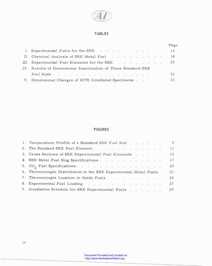
TABLES
1. Experimental Fuels for the SRE
n. Chemical Analysis of SRE Metal Fuel
W. Experimental Fuel Elements for the SRE
IV. Results of Dimen9ional Examination of Three Standard SRE
Fuel Rods.
V. Dimensional Changes of MTR Irradiated Specimens
FIGURES
1. Temperature Profile of a Standard SRE Fuel Rod
Z. The Standard SRE Fuel Element.
Page
16
18
25
32
33
6
II
3. Cross Sections of SRE Experimental Fuel Elements 12
4. SRE Metal Fuel Slug Specifications 17
5. UOz Fuel Specifications. 20
6. Thermocouple Distribution in the SRE Experimental Metal Fuels 23
7. Thermocouple Location in Oxide Fuels 24
8. Experimental Fuel Loading 27
9. Irradiation Schedule for SRE Experimental Fuels 29
iv
Document Provided and Located on: http://www.RocketdyneWatch.org
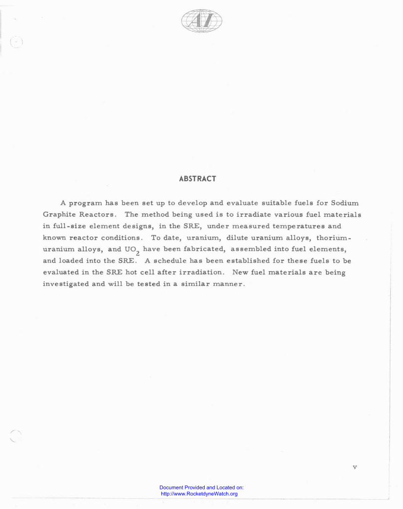
A program has
Graphite Reactors.
in full-size element
ABSTRACT
been set up to develop and evaluate suitable fuels for Sodium
The method being used is to irradiate various fuel materials
designs, in the SRE, under measured temperatures and
known reactor conditions. To date, uranium, dilute uranium alloys, thorium
uranium alloys, and UOZ
have been fabricated, assembled into fuel elements,
and loaded into the SRE. A schedule has been established for these fuels to be
evaluated in the SRE hot cell after irradiation. New fuel materials are being
investigated and will be tested in a similar manner.
v
Document Provided and Located on: http://www.RocketdyneWatch.org
~~
I. INTRODUCTION
Sodium Graphite Reactors (SGR) offer the potential advantages of high cool
ant temperatures, high heat-transfer rates, reasonable neutron economy, and
low cost electrical power. With the building of the Sodium Graphite Reactor
Experiment (SRE),l a program was established to provide a suitable fuel for
this reactor. The requirements of fuel for this system are principally: a) to be
capable of long burnup at high surface and center temperatures, b) to be low in
cost, c) to be amenable to economical reprocessing. The SRE experimental
fuel program is set up to develop both metallic and ceramic fuels for Sodium
Graphite Reactors. The operating limitations of burnup and temperature of
various fuels in the SRE will be established. Included in the development pro
gram is the evaluation of the overall fuel element design. The end result will
also include improved specifications for fuels with lower procurement cost,
and longer life. The information developed in the SRE will be useful to the
physical metallurgist, ceramist, and solid state physicist, in developing and
substantiating theories of irradiated fuel behavior.
The primary problem with metallic fuels operating at high surface tem
peratures, is swelling. This dimensional change results in a decreased density.
The phenomenon has not yet been fully explored, but the principal factors
believed to affect swelling in metal fuels are:
a) Center temperature.
b) Surface temperature.
c) Temperature difference (surface to center).
d) Total burnup.
e) Burnup rate.
f) Properties and structure of the fuel material.
g) Thermal cycling.
h) Phase change kinetics.
It is only recently that an attempt has been made to irradiate fuels at surface
temperatures over 700 0 F. The problem of swelling increases as the surface
I
Document Provided and Located on: http://www.RocketdyneWatch.org
temperature increases. To date, only a few widely scattered experimental data
are available, on the problem of swelling. 2. 3. 4 From this information, it appears
that each fuel material has a threshold temperature, or temperature range,
beyond which swelling increases at a rapid rate. It is not known whether the
surface or central temperature (or both) is the controlling factor. This tempera
ture range varies beyond 660 and lZOO° F and depends on factors such as burnup
rateJ
fuel composition and structure, and geometry. It does not presently appear
feasible to extrapolate irradiation data, from plate to cylindrical geomety. Simi
larly, extrapolation from small cylinders to large cylinders, is not recommended.
Each fuel design, and each fuel material, must be evaluated under the intended
operating conditions in order to predict their expected performance.
The primary difficulties experienced with ceramic base fuels are low ther
mal conductivity and low uranium atom density. These limitations increase the
size of the core with proportionately higher fuel costs. Additional ceramic fuel
problems that require investigation are: a) the amount of fission gas release,
and b) the extent of thermal ratcheting between the fuel and the cladding. As
with metal base fuels, the only feasible method of establishing limits of burnup,
heat transfer rates, and temperature, is to irradiate full-scale fuel elements
under deSign conditions.
The method being followed in accomplishing the goals of the SRE experi
mental fuel program is as follows:
a) Various alloys of metallic fuels are selected for test purposes on the
basis of thermal cycling, physical and mechanical property evaluation.
b) Samples of promising fuels are irradiated in the MTR under tempera
ture -monitored conditions.
c) Fuel element designs, suitable for testing experimental fuels in the
SRE, are developed.
d) Fabrication techniques are developed for promlsmg fuels, and all
processing and quality variations are carefully noted.
e) Fuel elements are assembled, and irradiated in the SRE under measured
temperature conditions.
2
Document Provided and Located on: http://www.RocketdyneWatch.org

f) Fuel materials, and fuel element designs, are evaluated in the SRE
hot cell after irradiation. Examination includes gross effects such as
dimensional changes, density changes, fission gas release, metallurgi
cal changes in structure, and physical properties.
g) The optimum fuel (or fuels) for use in SGR reactors, are selected. The
selection includes the establishment of temperature and burnup operat
ing limits and the material specifications required to produce the
selected fuel.
h) The economics of the entire fuel cycle are evaluated.
This report is restricted to the fabrication, irradiation conditions, and
irradiation damage of fuel materials. Studies of the nuclear, heat transfer, and
flow characteristics of fuel elements, have been carried out under other pro
jects. 1
The first round of experimental fuels has been fabricated and inserted in the
SRE. Irradiation schedules and examination procedures have been established.
The flexibility of the program permits the selection of new fuels, and the develop
ment of improved fabrication techniques. This report covers the results achieved
to date and outlines plans for future work.
3
Document Provided and Located on: http://www.RocketdyneWatch.org
II. OBJECTIVES OF THE SRE EXPERIMENTAL FUEL PROGRAM
The objective of this program. is to develop an economical fuel for SeR
reactors. To be economically feasible, the fuel must be capable of: a) long
burnup, b) a low fabrication cost, and c) low cost reprocessing. In order to
utilize the Na coolant in SCRs properly, the fuel must operate at high surface
and center temperatures, and at high surface heat fluxes. The fuel should have
a high uranium density and a low neutron absorption eros s section. The operat
ing limitations of fuel burnup and fuel temperature can be established only by
irradiating full-sized fuel elements under actual design conditions.
To achieve the objective of an economical fuel, all fuel variables starting
with fabrication, and continuing through the entire irradiation, must be investi
gated. Close attention to fabrication details, and material quality, is necessary
if future specifications and predictions of irradiation behavior are to be realistic.
This program encourages the development of improved low cost fabrication pro
cedures and handling techniques.
The final objective of this program is the selection of the rnost suitable fuel
materials and fuel element deSigns, for Sodium Graphite Reactors. The limiting
values of fuel burnup, fuel temperature, and rate of fuel power output, will be
established under actual SGR conditions. Realistic specifications for fuel pro
curernent will be established. These specifications will reflect the effect of
fabrication variables, chernical cornpositions, manufacturing tolerances, and
defects on irradiation behavior, to allow fabrication of minimum cost fuel elements.
4
Document Provided and Located on: http://www.RocketdyneWatch.org

III. SRE IRRADIATION CONDITIONS 1
The SRE loading presently consists of 43 fuel elements. With the reactor
operating at ZI Mw thermal, the average neutron flux in the fuel is approximately
1.3 x 10¹³
thermal and 1 x 10¹³
fast. The maximum power per channel is approxi
mately 530 kw. The Na inlet temperature is 52soF and the mixed mean Na outlet
temperature is 900°F. The individual fuel channel outlet temperatures vary due
to differences in Na flow and channel power output. The peak sodium. tempera
ture is limited to about 960· F by germinative grain growth and associated 10s8
of structural properties in the zirconium moderator cladding.s
Temperature profiles for SRE znetal fuel rods with a 43 element loading, and
no allowance for hot channel factors) have been calculated on the basis of a 1.3
to 1 peak-to-average vertical flux distribution. The calculated temperature pro
file for a fuel rod operating with a 525 0 F Na inlet and a 840 0 F Na outlet in the
central fuel channel of the SRE, is given in Figure 1. The maximum tempera
ture in Figure 1 is about 1010°F, which is appreciably less than the fuel tempera
ture of 1200°F originally calculated for a 37 element loading with allowance for
hot channel factors.
Control rods, burnup of the fuel, and the reactor fuel loading, will cause
deviations from the calculated flux distribution. Temperature profiles based on
actual flux distribution and measured fuel temperatures will be established for
each experimental fuel element. The actual flux distribution will be determined
from burnup profiles. It should be noted that both surface and center tempera
tures cover a wide range. Irradiation results, representing this sprea.d in tem
perature, will be useful in evaluating important parameters to design a metal
fuel element for operation at high temperatures.
5
Document Provided and Located on: http://www.RocketdyneWatch.org

CALCULATED TEMPERATURE PROFILE FOR UFUEL ROD IN THE CENTER CHANNEL OF THESRE WITH A 43 ELEMENT LOADtNG
r_=--_,::(,:C::"::A::NFN::E::L::::PO::W:::E::R=1":::5::'::0:::kW:::)==F====f------J------=j-60QoC1100 t-
"•
~ 800::J
!:tC<UJQ.::;;UJ>-
- - 400
- '00
u•
500 0 2 3
FEET UPSTREAM IN FUEL4
ELEMENT5 6
6
Figure 1. Temperature Profile of a Standard SRE Fuel Rod
Document Provided and Located on: http://www.RocketdyneWatch.org

IV. SELECTION OF FUELS
Due to the high operating temperatures (surface and central) employed in
the SRE, any fuel, including the original core loading of unalloyed uranium, must
be classified as experimental. Irradiation growth and swelling are the greatest
limiting factors on the life of metal fuels. Irradiation growth, which is due to
the anisotropic properties of alpha uranium, causes a change in shape with only
small density changes. Irradiation swelling, which is thought to be caused by
the nucleation and growth of small bubbles of fission gas, causes gross density
decreases in the fuel.
A. SRE FIRST CORE LOADING
The choice of alpha-rolled, beta heat-treated uranium, as fuel for the origi
nal core loading, was made in 1954. An alternate fuel) U - 2 wt 0J0 Zr alloys was
discarded at that time in favor of the unalloyed uranium, due to the sensitivity
of the U - 2 wt "70 Zr alloys to fabrication variables. 6. 7 It was originally expected
that the high fuel-slug temperatures (500 to 1200· F) would decrease the phenomena
commonly known as irradiation growth. The target irradiation exposure was
2500 Mwd/tonne, *
B. SRE SECOND CORE LOADING
As an alternate to uranium and dilute uranium alloys) a Th-U alloy was
chosen for test as a potential SGR breeder fuel. The physical metallurgy of
these alloys was studied under a separate project,8.9 It was hoped that both the
lack of anisotropy, and of phase change below 2500 0 F in the face -centered cubic
thorium lattice, would result in a fuel that could be irradiated to high burnup at
high temperatures with minimum distortion. 10 A Th - 7.6 wt "70 U alloy will be
evaluated as the main fuel in the second SRE fuel loading.
C. EXPERIMENTAL METALLIC FUELS
After selecting the first core loading) an investigation of the means of extend
ing the maximum radiation life beyond 2500 Mwd/tonne and the maximum operating
• Mwd/tonne will be used throughout this report as tbe unit of bumup. (Mwd/tonne is defined as the totalenetgy produced. e:Epressed in'megawatt days per 1000 k.ilograms of fuel.)
7
Document Provided and Located on: http://www.RocketdyneWatch.org
temperatures above 1200°F was initiated. Thermal cycling tests and metallo
graphic studies were conducted on dilute uranium alloys. Alloying compositions
investigated originally were limited to about 5 at. % maximum to minimize the
effect of alloying on neutron economy.
On the basis of resistance to thermal cycling, fine grain size, feasibility
of fabrication, and irradiation data from other sites, cast 2 wt % Zr, cast U - 1.5
wt % Mo, and powder compacted U - 1.2 wt % Mo, were initially chosen for test
in MTR capsules and SRE.
Recently the experimental program has been expanded to include the U - 3
wt %Mo alloy, in an effort to provide an alloy with greater radiation stability. 12
A potential breeder fuel alloy, with a composition of 5.4 wt 0;0 highly enriched
uranium in thoriwn, was chosen for test in the SRE. This composition approxi
mates the reactivity equivalent of the 2.78 wt % enriched uraniwn first SRE core
loading. This alloy has a microstructure consisting of a very fine uranium pre~
cipitate in a matrix of Th- U solid solution. The solubility of uranium in thorium
is about 10;0 at IlOO°F. 8 To test Th-U alloys in the MTR, a Th - 11 wt 0;0 U
alloy was required to provide SRE temperature conditions in a 3/8-in. diameter
pin.
There are presently no clear-cut criteria to use in selecting a metal fuel to
operate at elevated temperature. Three different approaches now being investi
gated as possible means of improving the irradiation damage resistance of metal
fuel elements at elevated temperatures are:
I} High creep strength fuels.
2) Metastable gamma phase uranium alloys.
3) High strength fuel claddings.
Small amounts of silicon or aluminum appreciably increased the creep strength
of the dilute U -Mo alloys. 13 Of these alloys, U - 3 wt 0;0 Mo - 0.5 wt 0;0 Si, and
U - 3 wt % Mo - 0.1 wt % AI, are now being prepared for test. The finely divided
second phase in these alloys may also act as nucleating sites for fission gas
8
Document Provided and Located on: http://www.RocketdyneWatch.org
atoms and minimize the fission gas atom mobility. A series of alloys consisting
of U - 3 wt"o Mo, U - 5 wt 0J0 Mo, U - 7.5 wt"o Mo, and U - 10 wt"o Mo, are
being prepared for test. These irradiations should establish the amount of gamma
stabilizer required to produce irradiation stability under SRE conditions. The
effect of irradiation on phase transformation kinetics in U -Mo alloys will be
investigated. Other metastable gamma alloys, such as U - 10 wt 0J0 Nb - 4 wt "0Zr, are under consideration. An attempt will be made to restrain the swelling
of uranium by use of high strength cladding materials such as Nb, Mo, or high
"strength Zr alloys.
D. EXPERIMENTAL CERAMIC FUELS
After a review of properties, such as thermal conductivity and compatibility
with Na, U02
was chosen as a ceramic fuel for test in the SRE. The existing
irradiation data of U02
indicates no gross problems with swelling or distortion
at high burnups and at central fuel temperatures up to the melting point of U02
. IS
However, a new series of problems arise with the use of U02 that require investi
gation, both in-pile, and out-of-pile. These problems include, 1) thermal ratchet":
ing, 2) the effect of irradiation on thermal conductivity, and 3) the amount of fis
sion gas release.
The physical properties, particularly the thermal conductivity, are very
important when ceramic and cermet fuels are used. Uranium atom density is
another important consideration. Uranium carbide presently looks very pro
mising from these two aspects and will be included in the SRE program, as soon
as a suitable fuel element can be fabricated. Other uranium compounds and
cermets are being investigated.
9
Document Provided and Located on: http://www.RocketdyneWatch.org

.41V. FUEL ELEMENT DESIGN
The standard SRE fuel elements are seven-rod clusters containing NaK
bonded uranium slugs, in type 304 stainless steel jackets (Figure Z). The active
fuel length of the element is 72 in. The 6.0-in. long by 0.750-io. -diameter slugs
of unalloyed uranium are bonded by 0.010 in. of NaK to the O.OlD-in. -wall stain
less steel jecket, for good heat transfer. The fuel element channels through
which the sodium coolant flows, are 2. 80-in. nominal diameter. The spacing
between rods is maintained by spirally wrapped spacer wires. The end fittings
position the rods and the element in the channel, and regulate the coolant flow.
The experimental fuel elements for the SRE are designed to equal the reacti
vity and the power generation of standard fuel elements. Experimental alloy
fuels of the proper enrichment are loaded into elements of the standard design.
In addition to testing di£!erent fuel materials the SRE irradiation tests will be
used to evaluate variation in fuel element design. Alternate designs contain the
proper quantity of fuel at the desired enrichment and provide adequate heat
transfer surfaces.
The cross sections of the alternate fuel elements to be tested in the SRE
are illustrated in Figure 3. In each case the fuel length is 72 in. and proper
positioning orificing fittings are provided.
A. SEVEN-ROD CLUSTER
The SRE core was designed for a fuel loading of 37 seven- rod fuel elements.
The seven-rod element is designed to provide adequate heat transfer surface to
limit the
thermal.
center fuel temperature to 1200 0 F, when the SRE is operating at 20 Mw
There are two possible disadvantages to this deSign:
1) If isotropic swelling of the fuel occurs, the fuel will have filled the
O.OIO-in. NaK bond annulus after 8% volume expansion. This expan
sion will exert pressure on the fuel jacket with the possibility of even
tual element rupture.
2) The nonsymmetrical £lux distribution in the seven-rod fuel element
will produce nonsymrnetrical thermal stress and radiation damage
which could cause slug warp.
10
Document Provided and Located on: http://www.RocketdyneWatch.org

HANGER ROO
SEVEN RODELEMENT
FUEL ROD JACKET (NoK FILLED)
16-tn. FUEL SLUGS (12)
~'OIOin 5.5. TuBE
O.OIOin No K BOND
0.75 in SLUG DIA.
SEC. A-A
~~.090 ,".(TYPICAL!
.,.
-t-- HELIUM FILLED EXPANSION SPACE
Figure 2. The Standa rd SRE Fuel Element
11
Document Provided and Located on: http://www.RocketdyneWatch.org

I. STANDARD 7- ROO
~~L__------l~%~_O.OIO"55 TUBE
~~~ "/'l 0.010" No K BONO
~~r---- ~t:--0.75· OIA. SLUG
A VARIATION OF THE ABOVE IS 0.720" OIA. SLUGS AND 0.025" No K BOND
A VARIATION OF THE ABovE IS 2.35"0.0. FUEL AND 0.040· No K BOND
2. LARGE HOL':L~O~W~ ---------~~i~-
3. 19 ROD U0 2
~C-_---------l 0.010·55 TuBE""0",@0>~0> """"..-"" """" v ~\':~- 0.002" H e.
~~'"'~ ~~~ 0.356" OIA. FUEL PIN
00~0V
~__ 0.015" 55 TUBE
~~_ 2.3I0",p.0.} FUEL1.786 1.0.
~~- 0.020" 55 TUBE
!..--m~\> .002" He.
~~~~----- ~~1l-d!~#!--o.old'ss TUBEL.l?~ ,ffL-- .505"0.0. FUEL
4. TUBULAR ~U;0~2~: -------~
Figure 3. Cross Sections of SRE Experimental Fuel Elements
NOTE: lncli'fidual leDgths are indicated in the detailed specifications.
12
Document Provided and Located on: http://www.RocketdyneWatch.org
The present metal fuel element design provides space in the NaK annulus to
accommodate about 30/'0 diameter increase. Therefore, two variations of metal
fuel slug designs which allow more space for fuel expansion will be tested in the
SRE. The first variation will be to increase the NaK bond to 0.025 in. with a
corresponding smaller diameter slug (0.720-in.) which will allow up to 200/'0
volume expansion. The other variation will be to fabricate a center core in the
fuel slug to provide increased volume for fuel
ques are to be attempted to reduce slug warp.
slugs about I in. long. The other technique is
design described below.
B. LARGE HOLLOW ELEMENT
swelling. In addition, two techni
One technique is to use short
the large hollow fuel element
The large hollow fuel element (Figure 3), which contains sixteen four-in. long
uranium cylinders, is an alternate design to the seven-rod cluster. It will reduce
the possibility of fuel warp and take advantage of possible fuel fabrication cost
reductions by using large fuel pieces. This design has the same cross sectional
fuel area (3.1 in. 2 ) as the standard seven-rod fuel element. However, in order
to provide an equivalent heat transfer surface, the diameter must be increased.
The original design allows only 3.750/'0 isotropic volutne expansion of the fuel
before the outer annulus is filled. If the outer annulus is increased from 0.015
to 0.040-in. by reducing the outside diameter of the slug from 2.400 to 2.350-in.
a 100/'0 volume expansion will be possible without interference. Isotropic swelling
would not decrease the inside diameter of the fuel; thus the present 0.025 in.
inside NaK annulus should be adequate. The O.OlO-in. wall of the inside jacket
tube is required to prevent buckling of the tube due to pressure developed inside
the fuel eletnent during irradiation.
C. 19-ROD UOl
In an effort to provide an SGR fuel which could be used for long burnups, UOZ
fuel elements were added to the SRE fuel progratn. Small fuel slug diameters
were required to avoid center melting of UOZ in the SRE, if the experitnental
element is to match a standard SRE fuel element in power generation. The 19 -rod
cluster (Figure 3) tneets this requiretnent.
13
Document Provided and Located on: http://www.RocketdyneWatch.org
D. TUBULAR UOZ
As an alternate to the 19-rod UOZ
fuel element, a tubular U02
element was
designed (Figure 3). It has the advantage of requiring fewer pieces of both U02
and jacket tubing. The amount of stainless steel in the fuel element is also
reduced.
14
Document Provided and Located on: http://www.RocketdyneWatch.org

'-'
VI, FABRICATION OF FUEL MATERIALS
In the development of fuels for a power reactor, considerable attention should
be paid to potential fabrication costs and eventual reprocessing of the fuel. To
compare the various known methods of fuel fabrication, and to initiate the develop~
ment of improved methods, the SRE experimental fuels were fabricated by several
different methods. The goal is a fabrication technique that is low in cost, has a
high yield, and is adaptable to remote techniques for reprocessing. A list of the
fuels fabricated for test in the SRE is given in Table 1.
Extensive fabrication records were required to evaluate the irradiation
behavior of the various fuels, to establish realistic inspection and quality control
procedures, and to evaluate the economics of the various fabrication techniques.
All metal slugs in the SRE program are numbered. The slug number relates the
slug to individual process variables such as ingot heat, extrusion rod, or sinter
batch. By use of the slug number, all of the material can be traced back to the
original containers of UF6' Although U02. pellets are not numbered, the batches
are isolated so that variations in processing procedures can be evaluated. Simi
larly, all fuel rods are labelled and the assembly sequence records carefully
maintained.
A. METAL FUEL FABRICATION
In the initial standard fuel loading for the SRE, 52. 30 unalloyed alpha-rolled,
beta heat-treated 2..78 wt 0;0 enriched uranium slugs, 3/4 by 6 in. were fabricated.
No development work was necessary prior to the enriched uranium processing.
Figure 4 shows the complete specification used for these slugs. Subsequent
dilute uranium alloy slugs, and Th-U alloy slugs, were fabricated to the same
specifications. Minor modifications were adopted for the powder-compacted
short slugs, and the large hollow slugs.
Each slug was visually inspected and dimensionally checked against the
specification. Most rejects were caused by surface seams and end cracks. Fifty
reject slugs with light seams, heavy seams, and end cracks, were accepted for
evaluation in the SRE. One of the purposes of the irradiation examinations is to
correlate performance with specifications. It is anticipated that by more liberal
15
Document Provided and Located on: http://www.RocketdyneWatch.org
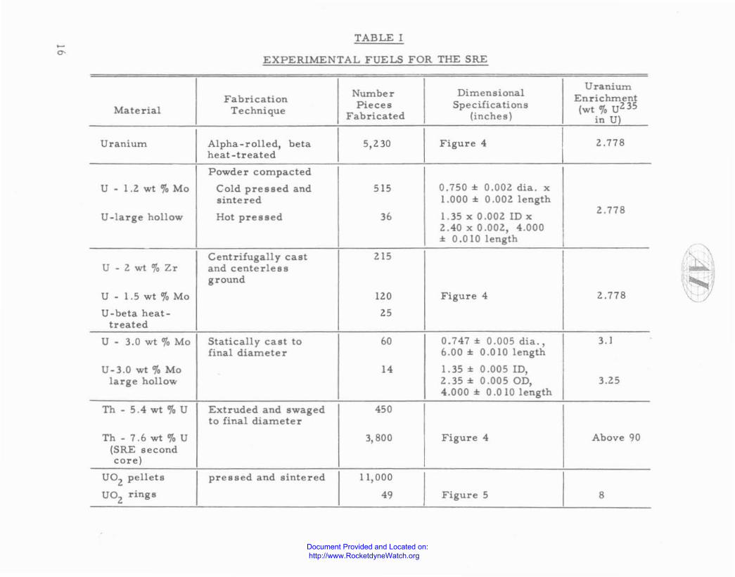
TABLE I
EXPERIMENTAL FUELS FOR THE SRE
Number DimensionalUranium
Fabrication EnrichmentMaterial Technique Pieces Specifications (wt ~, U235
Fabricated (inches) in U)
Uranium Alpha.rolled, beta 5,230 Figure 4 I 2.778heat-treated IPowder compacted
U - 1.2 wt '0 Mo Cold pressed and 515 0.750 ± O.OOl dia. xsintered 1.000 ± 0.002 length
U .large hollow Hot pressed 36 1.35 x 0.00210 x2.778
Z.40 x 0.002, 4.000± 0.010 length
Centrifugally cast 2[5U - Zwt,"oZr and centerles8
ground
U - 1.5 wt % Mo 120 Figure 4 2.778
U -beta heat- 25treated
U - 3.0 wt % Mo Statically cast to 60 0.7471: 0.005 dia., 3. Jfinal diameter 6.00::t: 0.010 length
U-3.0 wt % Mo 14 1. 35 ± 0.005 10,large hollow 2.35 ± 0.005 OD, 3.25
4.000 ± 0.010 length
Th - 5.4wt % U Extruded and swaged 450to final diameter
Th - 7.6 wt lifo U 3,800 Figure 4 Above 90(SRE secondcore)
DOZ pellets pressed and sintered 11,000
UOZ
rings 49 Figure 5 8
Document Provided and Located on: http://www.RocketdyneWatch.org

0-0.750" !0.002"DIAM~ I!O.005"-i 1========66<.OO)(f"~!f(0l..ooiCI0)""-======':
DIMENSIONAL SPECIFICA TIONSEnd radius deburred with no sharp corners.All surface., l50 root mean square.Maximum single-throw warp 0.003 in. per 6.00-in. length.Ends to be square with centerline to:z O.OOS-in.
MATERIAL QUALITY SPECIFICATIONSIsotopic Content: ::t: 0.005 at. "0 U2.35Purity: See Table Z.Density (min.); Unalloyed U 18.86 glee; U - 1.5 wt % Me 18.45 glee; U - 3.0 wt % Me18.l0 glee; U - Z.O wt % Zr 18.Z0 glee; Th - 5.4 wt ,"0 U 11.8 glee; Th - 7.6 wt % U 11.9 glee.Grain Size: Maximwn of O.ll mm.Alloy Content: ::t: 0.1 % of alloy element; from slug to slug and within one slug. Exception of+ 0.2. wt'" U in Th - 7.6 wt % U alloy.Metallurgical Quality: Uniform microstructure, preferred orientation mUl!lt be less thanreactor grade alpha-rolled, beta heat-treated uranium.Surface Subsurface and End 1m erfections: Seams or cold shuts longer than lIZ-in., widerthan 1 3Z-in., or deeper than I 3Z-in. shall be rejected. Only three defects within a lIZ_in.area on one piece are acceptable. Striations are cause for rejection only when in largequantity. Surface or 8ubsurface porollity, or shrinkage cavities, greater than 1/3Z-in. deepor 1/3Z-in. wide with two or more within a lIB-in. area on one slug are cause for rejection.Cracks greater than 1/3Z_in. in length are cause for rejection. Machining defects are causefor rejection. Any macrollcopic nonmetallic inclU8ion8 mU8t be removed and the 8lug mU8tpass all specification8 after removal.Destructive Teste: Representative sampl-es will be destructively examined for specificationverification.
Figure 4. SRE Metal Fuel Slug Specifications
specifications the process yield will be substantially increased and the fuel cost
reduced. Samples were taken throughout the fabrication cycle for isotopic and
spectrochemical analysis. Table n lists the typical chemical impurity analysis
of the fuel. Samples from each rolled rod were also retained for metallographic
analysis.
The various fabrication techniques listed in Table I ~ere first used to pro
duce unenriched process development slugs, which were evaluated for surface
specifications, internal soundness, chemical homogeneity, and metallurgical
structure. The uranium feed material for the enriched uranium alloy slugs, was
rejected slugs, and end crops from the fabrication of the enriched unalloyed
17
Document Provided and Located on: http://www.RocketdyneWatch.org
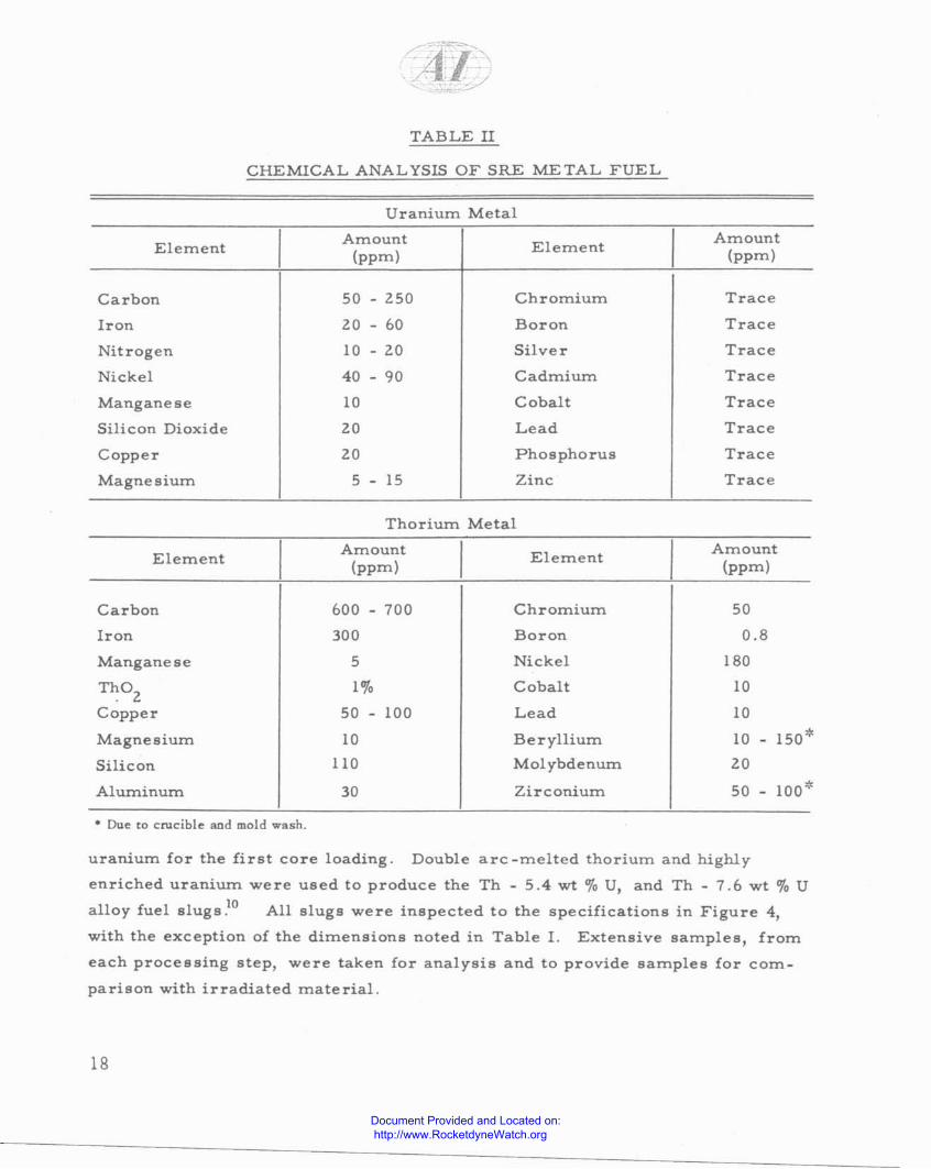
TABLE II
CHEMICAL ANALYSIS OF SRE METAL FUEL
Uranium Metal
ElementAmount
(ppm)Element
Amount(ppm)
Carbon
Iron
Nitrogen
Nickel
Manganese
Silicon Dioxide
Copper
Magnesium
50
lO
10
40
10
lO
lO
5
l50
60
lO
90
15
Chromium
Boron
Silver
Cadmium
Cobalt
Lead
Phosphorus
Zinc
Trace
Trace
Trace
Trace
Trace
Trace
Trace
Trace
Thorium Metal
ElementAmount
(ppm)Element Amount
(ppm)
Carbon 600 - 700 Chromium
Iron 300 Boron
Manganese 5 Nickel
ThOl
1% Cobalt
Copper 50 100 Lead
Magnesium 10 Beryllium
Silicon 110 Mol ybdenurn
Aluminum 30 Zirconium
.. Due to crucible and mold wash.
50
0.8
180
10
10
10 - ISO'
lO
50 - 100'
uranium for the first core loading. Double arc-melted thorium and highly
enriched uranium were used to produce the Th - 5.4 wt ero u, and Th - 7.6 wt % U
alloy fuel slugs ,10 All slugs were inspected to the specifications in Figure 4,
with the exception of the dimensions noted in Table 1. Extensive samples, from
each processing step, were taken for analysis and to provide samples for com
parison with irradiated material.
18
Document Provided and Located on: http://www.RocketdyneWatch.org

•"'-. _. -, .~
Fuel specimens for irradiation in the MTR were fabricated in the form of
0.375 ± 0.005-in. diameter x 1.500 ± O.OlO-in. long pins. Whenever possible
the SRE fuel fabrication techniques, and quality specifications were utilized.
Uranium enriched to 10 wt 0J0 U235
was required to duplicate SRE fuel tempera
tures in these small diameter uranium and uranium alloy pins. The Th~U alloy
fabricated {or MTR testing contained 11 wt 0J0 of highly enriched uranium.
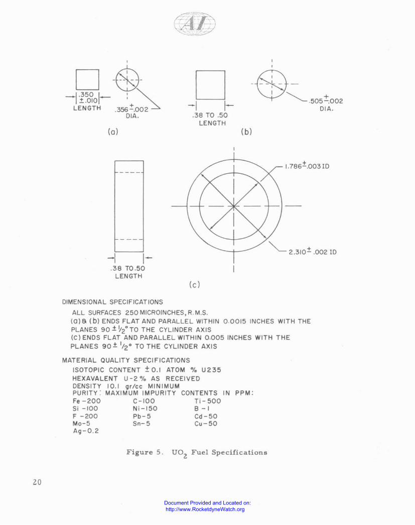
B. UOZ
FUEL FABRICATION
For an initial test of UOZ
in the SRE I 11,000 pellets and 49 rings were fabricated
cated. The pellets were 0.356-in. diameter for use in 19-rod clusters and
0.505-in. diameter for use as center rods in tubular elements. The rings for
the tubular elements were 2.310-in. OD and 1.786-in. lD. The UOZ
pellets and
rings were fabricated to the specification shown in Figure 5. All U02
powder
was produced from the same withdrawal of eight wt % enriched UF6' The U02
powder was prepared by an ammonia precipitation technique. Since numbering
of the small pellets is not feasible, the pellets were kept segregated by process
lot so that any effect of processing ort the U02
irradiation behavior in the reactor
can be isolated. All 0.356-in. diameter pellets were produced by cold pressing
and sintering which produced pellets to the dimensional specification without
grinding. The resultant pellets had an oxygen to uranium ratio of Z.02. The
fabricator also produced pellets with two 0.032-in. axial holes, one at the cen-
ter axis, and one 0.030 in. from the edge; to be used for thermocouples for tem
perature monitoring. The U02 rings were fabricated by two suppliers to evaluate
processing techniques.
19
Document Provided and Located on: http://www.RocketdyneWatch.org
I-,
D -&---1.350 1_ '~
1.t·OID 'LENGTH .356:!:.002
OIA,
(0)
1-.38 TO.50
LENGTH
D-I I-
.38 TO .50LENGTH
(C)
-e-~.505:!:.002DIA .
(b)
1.786±.0031D
""'--- 2.310± .002 10
20
DIMENSIONAL SPECIFICATIONS
ALL SURFACES 250 MICROINCHES, R. M.S.(0)6 (bl ENDS FLAT AND PARALLEL WITHIN 0.0015 INCHES WITH THEPLANES 90 ± '12
0 TO THE CYLINDER AXIS(C) ENOS FLAT AND PARALLEL WITHIN 0.005 INCHES WITH THEPLANES 90 ± 1/20 TO THE CYLINDER AXIS
MATERIAL QUALITY SPECIFICATIONS
ISOTOPIC CONTENT ±0.1 ATOM % U235HEXAVALENT U -2 % AS RECEIVEDDENSITY 10.1 gr/cc MINIMUMPURITY: MAXIMUM IMPURITY CONTENTS IN PPM:Fe-ZOO C-JOO Ti-500Si -100 Ni-J50 B-1F -200 Pb-5 Cd-50Mo-5 5n-5 Cu-50AO-0.2
Figure 5. UOZ
Fuel Specifications
Document Provided and Located on: http://www.RocketdyneWatch.org
VII. IRRADIATION OF FUELS
A. PRE-IRRADIATION EVALUATION
As metallic fuels were received from the vendor, samples of the fuel were
evaluated for chemical homogeneity, microstructure, microhardness, density,
and physical integrity. All cast slugs were gamma-graphed to determine the
amount of center line shrinkage.
Oxide pellets and rings were rneasured for density and dimensions. Since
the pellet diameter is expected to affect the center temperature of the fuel, by
varying the size of the helium gap, the pellets were segregated into groups by
diameter.
B. ASSEMBLY OF EXPERIMENTAL FUEL ELEMENTS
After pre-irradiation evaluation, the fuel materials were divided into batches,
with each batch containing the amount of fuel required for one fuel rod. Each metal
fuel batch contained only one fuel composition produced by a single fabrication
technique. Variations in slug surface conditions and slug processing lots were
included in each batch. One·half in. wafers were cut from two slugs in each
experimental metal fuel batch, prepared for metallographic examination, and
weighed, to determine density. After photomicrographs were taken, each wafer
was returned to its own batch. This technique provides for pre- and post-irradia
tion examination of the same area. Oxide fuels were batched by selecting pellets
from the diameter groups so that each batch contained pellets with uniform
dimet:Lsional tolerances, and similar processing and fabrication histories.
After batching, each group of fuel units was assembled into one fuel rod. A
canning procedure was established for standard SRE metallic fuel which consisted
of: 1) electropolishing each slug, Z) vacuum outgassing the slugs at lOOO·F, to
remove hydrogen, 3) loading 12 slugs (one batch) into a fuel jacket with a welded
bottom end cap, 4) vacuum out-gassing 21 rods at 750· F in a multi-rod loading
machine 5) loading NaK to a specific level above the fuel slugs, and 6) welding
top-end caps under a helium-argon atmosphere. 1 Quality control procedures on
the assembled rod included an eddy current inspection for NaK bond continuity,
and a helium-leak inspection of the welds.
21
Document Provided and Located on: http://www.RocketdyneWatch.org
Oxide fuel rods are fabricated by a similar procedure which consisted of
welding caps on loaded rods in the multi rod loading machine under a helium
atmosphere. The helium acts as the heat transfer medium between the U02 and
the cladding. A NaK bond is not used since the center temperature of the U02
fuel is above the boiling point of NaK. There would be a possibility of high NaK
vapor pressures being generated in a NaK-bonded UOZ element when the U02pellets fractured.
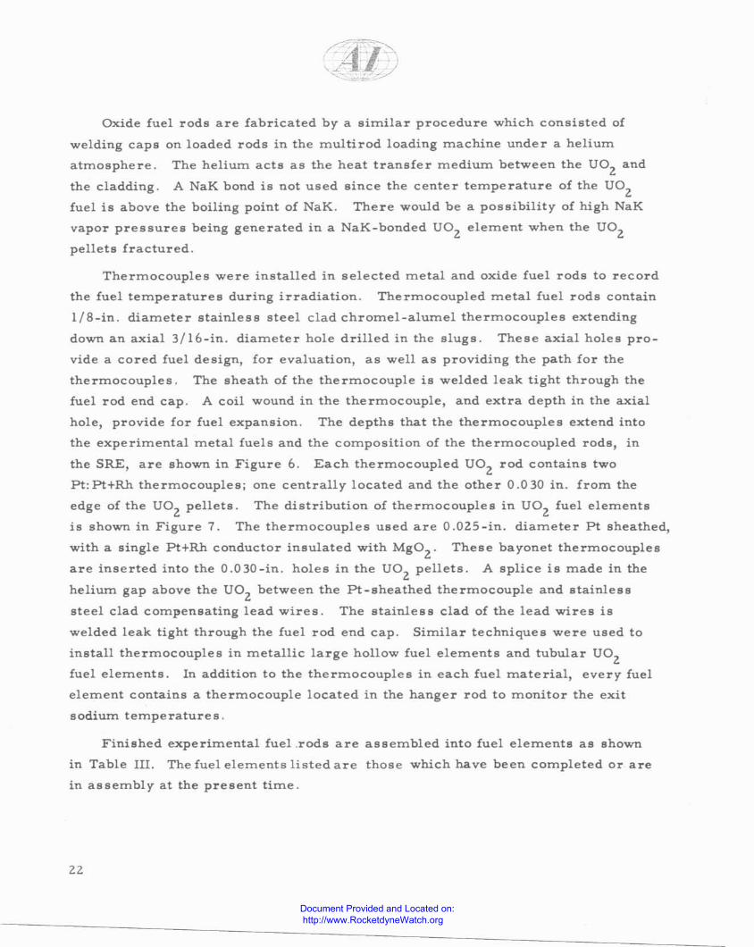
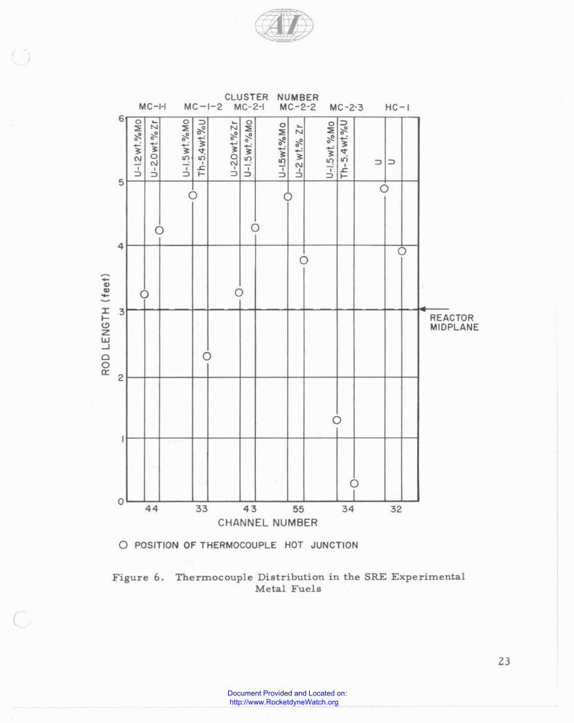
Thermocouples were installed in selected metal and oxide fuel rods to record
the fuel temperatures during irradiation. Thermocoupled metal fuel rods contain
lIB-in. diameter stainless steel clad chromel-alumel thermocouples extending
down an axial 3/16-in. diameter hole drilled in the slugs. These axial holes pro
vide a cored fuel design, for evaluation, as well as providing the path for the
thermocouples. The sheath of the thermocouple is welded leak tight through the
fuel rod end cap. A coil wound in the thermocouple, and extra depth in the axial
hole, provide for fuel expansion, The depths that the thermocouples extend into
the experimental metal fuels and the composition of the thermocoupled rods, in
the SRE, are shown in Figure 6. Each thermocoupled U02 rod contains two
Pt:Pt+Rh thermocouples; one centrally located and the other 0.030 in, from the
edge of the U02
pellets, The distribution of thermocouples in U02 fuel elements
is shown in Figure 7. The thermocouples used are O.OZS-in. diameter Pt sheathed,
with a single Pt+Rh conductor insulated with MgOZ
' These bayonet thermocouples
are inserted into the 0.030-in, holes in the UOZ
pellets. A splice is made in the
helium gap above the UOZ
between the Pt-sheathed thermocouple and stainless
steel clad compensating lead wires. The stainless clad of the lead wires is
welded leak tight through the fuel rod end cap. Similar techniques were used to
install thermocouples in metallic large hollow fuel elements and tubular UOZ
fuel elements. In addition to the thermocouples in each fuel material, every fuel
element contains a thermocouple located in the hanger rod to monitor the exit
sodium temperatures,
Finished experimental fuel ,rods are assembled into fuel elements as shown
in Table III. The fuel elements listed are those which have been completed or are
in assembly at the present time.
22
Document Provided and Located on: http://www.RocketdyneWatch.org
~'-. ~
. I .
MC-HCLUSTER NUMBER
MC-I-2 MC-2-1 MC-2-2 MC-2-3 HC-I
CTORPLANE
323433 43 55
CHANNEL NUMBER
44
0 ~ 0 ::> ~ 0 0 0 ::>
'" N '" ~N '"
~
'" '"'" '" '" '" '" '" N •• • ~~ • • '" '" '" ~
~ '" ~ • '"~ ~ •'" '" ~ • ~
'" '" '" '" '"~
'" <t~
0 on on 2 "1 '" .,;oj ~
, - on'"
"1 , ::> ::>, , , ~, , , -, , ~::> ::> ::> f- ::> ::> ::> ::> ::> f-
a a
a aaa
a aREAMID
a
aI
?
6
5
o
4
I 3>'-"ZUJ...JCloa: 2
--""--
a POSITION OF THERMOCOUPLE HOT JUNCTION
Figure 6. Thermocouple Distribution in the SRE ExperimentalMetal Fuels
(
23
Document Provided and Located on: http://www.RocketdyneWatch.org
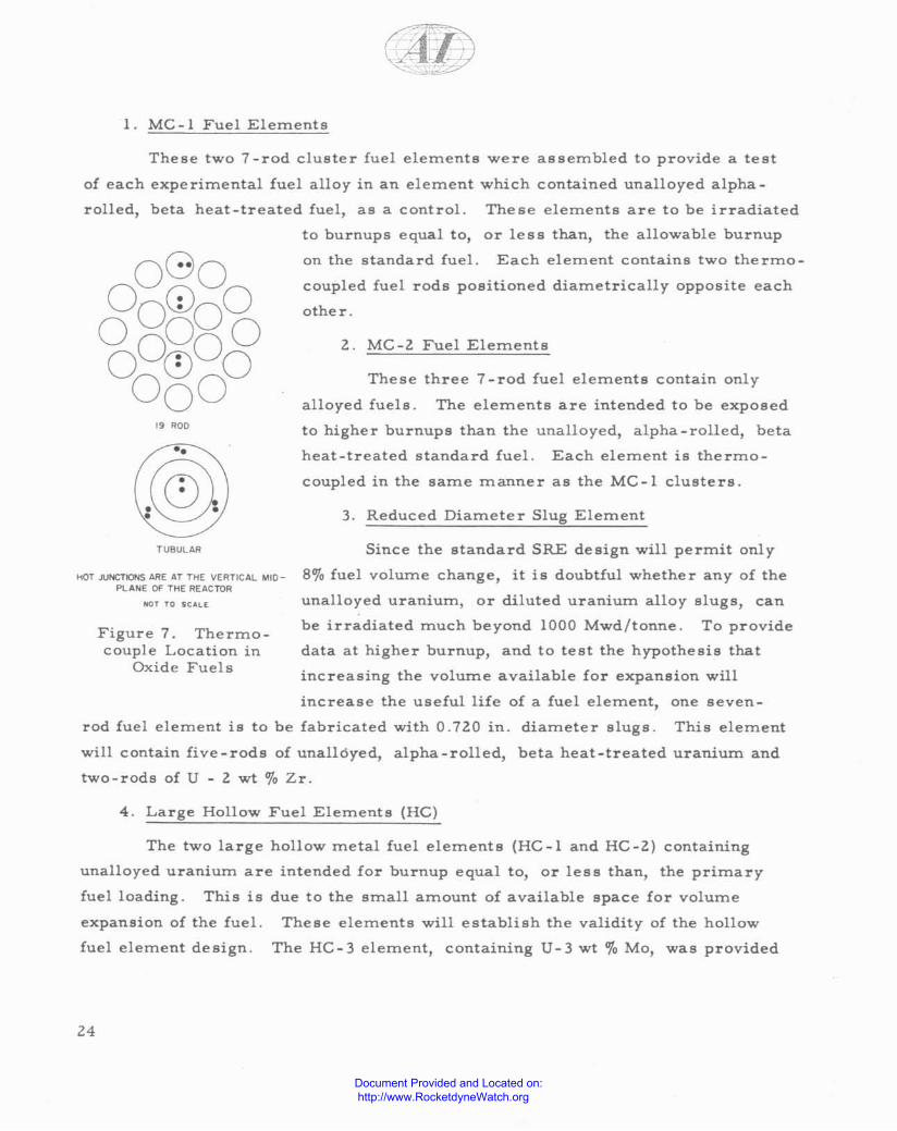
1. MC -1 Fuel Elements
coupled fuel rods positioned diametrically opposite each
other.
l. MC-l Fuel Elements
3. Reduced Diameter Slug Element
These three 7 -rod fuel elements contain only
alloyed fuels. The elements are intended to be exposed
to higher burnups than the unalloyed, alpha-rolled, beta
heat-treated standard fuel. Each element is thermo
coupled in the same manner as the MC-I clusters.
••
19 '100
These two 7-rod cluster fuel elements were assembled to provide a test
of each experimental fuel alloy in an element which contained unalloyed alpha
rolled, beta heat-treated fuel, as a control. These elements are to be irradiated
to burnups equal to, or less than, the allowable burnup
on the standard fuel. Each element contains two thermo-
TUBULAR Since the standard SRE design will permit only
I10T AlNCT10NS ARE AT THE VERTICAL 10410- 80;0 fuel volume change, it is doubtful whether any of thePLANE OF THE REACTOR
Figure 7. Thermocouple Location in
Oxide Fuels
unalloyed uranium, or diluted uranium alloy slugs, can
be irradiated much beyond 1000 Mwd/tonne. To provide
data at higher burnup, and to test the hypothesis that
increasing the volume available for expansion will
increase the useful life of a fuel element, one seven~
rod fuel element is to be fabricated with 0.7l0 in. diameter slugs. This element
will contain five-rods of una1l6yed, alpha-rolled, beta heat-treated uranium and
two-rods of U - l wt 0;0 Zr.
4. Large Hollow Fuel Elements (HC)
The two large hollow metal fuel elements (HC-l and HC-l) containing
unalloyed uranium are intended for burnup equal to, or less than, the primary
fuel loading. This is
expansion of the fuel,
fuel element design.
due to the small amount of available space for volume
These elements will establish the validity of the hollow
The HC-3 element, containing U-3 wt 0;0 Mo, was provided
24
Document Provided and Located on: http://www.RocketdyneWatch.org

N<n
TABLE 1Il
EXPERIMENTAL FUEL ELEMENTS FOR THE SRE
FuelOut.lde
Fuel ElementUnaUoyed U U - Z U - 1.5 Th _ 5.4 Diameter
D.,ianation ,a-Heat- Treated wt " ZrU - I.Z wt" Mo
'Nt " MoU_3wt"Mo
~~uFu.1(In. J
...... .,ol1ed can Cut Powder
I C.lt C.,t Extrudedcompacted
7.rod metal fuel mixedclulteu
Me-I-l Z· , , , , , 0.750
Me.t.Z Z , , , , , 0.750
Me·Z.l Z , , , Z 0.150
MC-Z-Z , Z Z Z 0.750Me_Z_] Z , , , Z 0.750
Reduced d.1 ..meter , Z D.no
Metal lara" hollowelement
HC.I Hot pr,,"ed U c:yUnde ... Z.40
He·Z Hot pu....d U cylind" ... Z.40
He-) Cut U • 3 wt " MQ cylindefl Z.35
UOZ 19-rod
CO.I Pr.. lled and 'intered UOz
0.35/0
UOz tubular
IHO·I Pre lied and lint. red UOZ
Z,310
• Indicates number of rods of given alloy in tbe czperimencal fuel element. These fuel elements arc presently in the SRE or in the finalstages of fabrication.
Document Provided and Located on: http://www.RocketdyneWatch.org

with 100/0 volume expansion of the fuel and is expected to go to greater burnup
than the primary fuel loading. This is a result of the increased expansion volume
and of the alloy fuel material. Each hollow fuel element contains two thermo
couples positioned to read maximum fuel temperatures.
5. 19 -Rod UOZ
Fuel Elernent
The 19-rod UOZ
fuel element will be used to establish the validity of its
design. The effect of variations in UOl
pellet diameters and densities on radia
tion behavior will be evaluated. Thermocouples are located near the vertical
midplane: of the element to record maximum fuel temperatures. The location of
two thermocouples within each rod, one at the center, and one just below the
surface, is expected to provide some data on the thermal conductivity of irradiated
UOZ ·
6. Tubular UOZ
Fuel Element
Irradiation behavior of the tubular UOZ
fuel elements will be used to evalu
ate UOl
rings and pellets with different dimensional and density tolerances. Ther
mocouples are located near the vertical midplane of the element to record maxi
mum fuel temperatures.
C. SCHEDULE OF IRRADIATIONS
The initial loading of experimental fuels is shown in Figure 8. In order to
achieve the highest rate of burnuPl experimental metal fuels have been loaded
into the central region of the SRE. Due to uncertainties in the thermal conducti
vity of the first UOl
fuel elements, a UOl
19-rod fuel element was loaded into
an outer channel where flux and temperature are relatively low. Localized over~
heating of the fuel channel during reactor scrams is a potential problem with UOl
fuel elements under present SRE sodium flow conditions. Overheating might
result from the large amount of heat stored in a UOl
fuel element, as compared
to the metal fuel element. The initial SRE tests on the 19 ~rod UOZ
fuel element
indicate that the element is compatible with present SRE conditions in an outer
fuel channel.
The present loading of experimental fuels provides a distribution of fuel
thermocouples as shown in Figure 6. Originally five standard unalloyed uranium
26
Document Provided and Located on: http://www.RocketdyneWatch.org

47
590
•25
•71
o7776
o81
75
•80
74
o79
520
•650
072
78
l/
t0,
O2N 0, .4 05 0 6 0 7
SRE CORE CONFIGURATION:WITH FIRST EXPERIMENTAL FUELS LOADED
LEGEND - FUELELEMENT DESIGNATIONS:
• STANDARD
() "C-I
() "C-2
o LARGE HOLLOW
~ 19ROD U02
<:> TUBULAR U02
o CONTROL RODS
o OTHER REACTOR HOLES
( Figure 8. Experimental Fuel Loading
27
Document Provided and Located on: http://www.RocketdyneWatch.org

fuel elements containing thermocouples, were loaded into outer fuel channels.
These thermocouples failed during the initial hours of full-power operation, due
to failure of either the insulated lead wires, or the splices in the shield plugs.
The experimental fuel elements were modified so that stainless steel clad thermo~
couples extend all the way to the reactor face. These modified thermocouples
have operated satisfactorily.
The scheduling of fuel element removals has been established to satisfy two
requirements: 1) the maximum limit of burnup for the present unalloyed core
loading must be determined so that the present fuel can be utilized fully and the
Th ~ 7.6 wt % U fuel loading can be scheduled into the SRE, with a minimum of
reactor down-time, 2) the unalloyed uranium fuel and the experimental fuels are
to be examined at roughly equal fractions of expected maximum burnup, based
on fuel distortion. By this schedule, the mechanisms and variables of radiation
damage can be properly evaluated. In addition to removing fuel elements for
destructive examination to evaluate fuel slug distortion, periodic nondestructive
examinations are made to insure gross fuel element integrity. Fuel elements
are examined visually in the hot cell, and fuel rod dimensions are measured
without removal from the element.
The schedule which has been followed through the first 1100 Mw days of
reactor operation and the tentative schedule for the remainder of the estimated
life of the first core loading is shown in Figure 9. The examinations carried
out during the first 1100 Mwd of SRE operation were: 1) after about 50 Mwd/tonne
at low temperature, 2) after about 80 Mwd/tonne which included the first full
power and design temperature run, and 3) after about 300 Mwd/tonne consisting
primarily of steady full~power operation. These destructive examinations of
standard seven~rod fuel elements established that the fuel element design was
functioning properly and established a zero point on which to base further full
power operation results.
D. MTR TESTS
To obtain advance information on radiation stability, at SRE temperatures,
and to eliminate unpromising fuels from further consideration, irradiation tests
are conducted in the MTR. The irradiations are conducted in capsules designed
28
Document Provided and Located on: http://www.RocketdyneWatch.org

S.R.EFUEL CHANNELRING NUMBER
MEGAWATT DAYS Of S.R.E. OPERATION
200 400 600 800 1000 1200 1"'00 1600 IBOO 2000 2200 2"'00 2600 2800 JOOO
ClNTDl .. til. MC H I H C -3 CONT. -50) MWOIT I 1000 MWO/T
," '"
MC -1-2 -I800 MWD/T
'21M C -2-1 I, " 1100 MWO/T
,"
STANQARO FUEL I MC 2-2 com- - -300 MWO/T 1500 MWO/T
MC -2 J COOT.," (3) -2000 MWOIT
, " STANOARO ELEMENT EXAMINEO VISliALLY WRING EACH SHlfTOOWN
1- H C-I "' 2 CONT2 " '31 - -400 MWO/T 800 MWD/T
• 20 (3) U02 19 '00 com. -I~
TUSULAR• 10 '31 CON...!-
,,}(21,,}
II
STANDARD FUEL REMOVED AND EXAMlt'£O AFTER 50 MWDITSTANDARD FUEL REMOVED AND EXAMINED AFTER 80 MWD/TSTANDARD FUEL REMOVED AND STOREDREMOVAL FOR HOT CELL EXIMINATlON
Figure 9. Irradiation Schedule for SRE Experimental Fuels
(,
to produce maximum SRE center and surface fuel temperature conditions in
3IB-in. diameter fuel pins. The central temperature of the fuels is measured
with a thermocouple. Six assemblies, each containing five or six specimens,
have been irradiated..Unalloyed alpha-rolled beta heat-treated U, U - 1.2 wt 0/0
Mo, U - 2 wt OZo Zr, and Th • 11 wt % U were tested. Details of these irradiations
have been reported separately. 16
29
Document Provided and Located on: http://www.RocketdyneWatch.org

VIII. HOT CELL EXAMINATION
After an SRE fuel element has reached its prescribed burnup, the reactor
is shut down. The element is cooled until the afterglow temperature does not
exceed 1200· F, during subsequent manipulation. The fuel element is removed
from the reactor with a shielded cask, washed free of Na in a wash cell, and
lowered into the SRE hot cell. During these operations the fuel temperature of
the experimental fuel elements is monitored to guard against overheating. The
afterglow heating data will contribute to improved cask and wash cell design.
In the hot cell, the general appeara.nce of the element, fuel jacket diameters,
and fuel rod straightness are determined. Photographs are taken at each exami
nation. Elements removed for visual examination only, are then returned to the
reactor.
When the element is to be destructively examined, the metallic fuel rod, or
rods to be examined, are removed from the cluster and decanned. Fission gas
release will be determined on both experimental metal and U02
fuel rods.
Decanned metal slugs and clad U02
rods will be given a complete dimensional
inspection. Dimensional inspection for diameter, length and warp has been
made on the fuel elements examined to date. In future experimental fuel exami
nations, density measurements also will be taken on full-size slugs and on the
wafers that were canned as part of the fuel rods.
Selected metal slugs and U02
rods will be sectioned to provide metallographic
specimens and burnup samples. Gamma-counting techniques and burnup analysis
will establish the burnup profile along the length of the fuel rod. The metallo
graphic specimens will be available for post-irradiation metallography, micro
hardness, and annealing studies.
30
Document Provided and Located on: http://www.RocketdyneWatch.org
IX. IRRADIATION RESULTS
A. SRE RESULTS
Nondestructive examinations of the seven-rod elements and the hollow ele
ments, after 1100 Mw days of SRE operation, have revealed no distortion of
either the fuel elements as a whole or the individual jacket tubing. Three fuel
rods containing unalloyed alpha-rolled, beta heat-treated slugs have been
destructively exam.ined in detail. A tabulation of the results of these examina_
tions is given in Table IV. Slug warp apparently occurs at very low burnups, but
the effect either saturates with burnup, or is restrained by the cladding. This
initial warp may be caused by the relief of residual fabrication stresses. Slug
length increased progressively with burnup. It is interesting to note that the
amount of length change is roughly proportional to the relative flux over the
entire rod, with no evident effect of temperature. Diameter increases were
noted only on the highest burnup slugs. Since bwnping on the slug surfaces and
the preirradiation tolerances practically invalidate any calculation of density
changes, any conclusions regarding swelling will have to await more precise
density measurements. A more detailed evaluation of the results will be made,
when an accurate burnup profile is available, which will also allow a more com.
plete temperature profile to be calculated.
B. MTR RESULTS
Five MTR irradiation assemblies have been opened for postirradiation exami
nation. Due to difficulties in reproducing SRE conditions with 3/8-in. fuel pins in
the MTR, only fragmentary information was obtained on unalloyed U and U - 2 wt
% Zr. However, neither of these fuels appeared promising on the basis of quali
tative observations.
Four U - 1.2 wt OJo Mo fuel pins were examined quantitatively for dimensional
and density changes. The results of these examinations is given in Table V.
These tests indicate that this alloy will swell appreciably after 2000 to 3000 Mwdl
tonne irradiation at fuel temperatures between 800 to 1200 0 F.
Th • 11 wt OJo U did not swell appreciably during MTR tests under SRE con-r
( ditions. A total of 17 specimens were evaluated for postirradiation density and
31
Document Provided and Located on: http://www.RocketdyneWatch.org

TABLE IV
RESULTS OF DIMENSIONAL EXAMINATION OF THREE STANDARD
SRE FUEL RODS
Burnup 50 Mwd/tonne 80 Mwd/tonne 300 Mwd/tonneFuel Temp. Less than 750°F Less than lOOO·F Lesa than 1000· F
~ . ~ . ~ .0_ 0_ 0_.. .. .- .. .. .- .. .. .-• ~~ • .<: ." • .<: .-
Slug No. • • • • • • f-<:=; • • • f-<:=;.. ~ . .. .<: • ..~ . ...<: • ..~ . ...<: •.... ·~ .. . - .... .~ .. . - .... ·~ .. . -• E0 • .. 0
_0. • E 0 " .. 0_0. • E0 • .. 0
_ 0.
• • • .0. ... • •• .0. ... • • • .0. ...> .... .c: > • .<: o • > .... .c: > • .<: o • > ... .c > • .<: o •«QU «..:lU u;;:t «QU «..:lU oo~ «QU «..:lU C;;~
Il (top) 0.0 0.1 4 0.0 0.3 16 0.0 1.0 II
11 0.0 N.R. 5 0.3 0.3 7 0.3 1.l l7
10 0.0 N.R. 10 0.1 0.3 3 0.3 1.l 22
9 0.0 0.1 8 0.0 0.5 25 0.5 1.4 20
8 0.0 N.R. 26 0.0 0.4 12 0.3 1.5 26
7 0.0 0.2 7 0.0 0.6 23 0.4 1.5 19
6 0.0 N.R. 4 0.1 0.7 25 0.4 1.6 23
5 0.0 0.2 8 0.0 0.7 26 0.7 1.8 26
4 0.0 N.R. II 0.1 0.6 22 0.1 1.5 18
3 0.0 0.3 18 0.0 0.6 21 0.1 1.3 22
2 0.0 N.R. 17 0.0 0.6 24 -0.1 1.2 14
1 (bottom) 0.0 0.1 6 0.1 0.3 10 0.0 1.0 16
(Average) I 0.0 I 0.2. 10 0.0 0.5 17 0.3 1.4 21
NOTE: I) Changes are positive unless labeled aegati..-e.2) Due to preinadiauoo tolerao.ces diameter changes arc ± 0.3" aad lengtb changes ate! 0.2".3) All fuel .as alpb.·rolled, be:ta·beaHreau:d.4) TClIIperatures reprcSftlt ma1imum central temperatUre.
dimensional changes. Included were fuel pins irradiated to burnup greater than
10,000 Mwd/tonne, and fuel pins with measured center temperatures up to 149soF.
Details of the irradiation conditions and the postirradiation evaluation are given
in Table V. The capsule designs, the details of the irradiation, and the detailed
results for the MTR irradiations have been reported separately. 16
3Z
Document Provided and Located on: http://www.RocketdyneWatch.org
TABLE V
DIMENSIONAL CHANGES OF MTR IRRADIATED SPECIMENS
Me"ured Central C,lcll1at"d SurfaceM....lmumSpecimen Temperature Temperature Burnup Fhalon ~er <;c lnCUI •• In Incr""" III Sample
Compoaltlon (OF) (OF)(Mwd/tonne") (x 10 0) Diameter
VolumeNAA-1S.(wt ,.,
I .., (,., fR.n., Avert,." """ Averl."
U.1.2Mo 8)0 to '" '" loSS to 555 "8 2.,400 IZ ,., ",..
U.I.ZMo IOSll to '" on 825 to 740 '" 3,100 1.6 " " ,-,U-I.l.Mo IUS 10 '" 1017 980 10 715 '" Z,IOO ... U 6.' .-,U-I.l.Mo IUO to .., 1052- 890 to 175 '" t, lOll ... '.6 '-' .-,Tb.IIU 1100 to 1000 1059 8':l'l to 82.0 866 2.,900 ... 1.6 0.47 HTh_llU 1300 to 1110 117Z lOMl 10 905 '" 2,900 ... '.8 0.18 ,- ,Th.llU IllS to 11'15 U14 lOGO 10 'In '" Z,900 ... ... 0.86 ,-,Th·lIU IZ30tolZIS IZ 19 10115 10 'I'll '" 2.,900 ... U L' ).)
Th_llU - - - - Z,'lOO L. U 1.6 ,-.Th.IIU 1135 to 10lG 1071 92.5 to 82.5 '" 5,400 .., '.7 '-' 7-6Th-llU IUO 10 1160 1198 1005 to 950 '" 5,900 ... ... '.7 7_'Th_llU IZS5101115 1187 IOZS to 910 '" b, lOll ,., L) .. , 7_'Th.IIU 1300 to 1090 1176 1060 to 890 '" 6,300 ,., .. .. 7-'Th-IlU 1415101163 IZ5Z 1150 to 950 IOU 6,4<10 '-' '-' ,., 7-'Th_llU 1495 to '" 1130 IUO to 760 '" 1.,600 '-' ••• '-' 7-'Th·IIU - 970 5 - 800' 9,100 ,., U '-' 6-6Th-IIU - 10)05 - 850' 9,700 ... U '-' 6_ ,
Th.IlU - 11001 . - 900' 10,700 ,.. U ••• 6_'Th.lIU - 1100 5 - 900 1 10,800 ,., L' '.8 6-'Th·llU - 1100 5 - 900' 11,100 '.6 L7 .., 6_'Th_llU - 1100 5 - 900 5 11,000 ).) U <., 6_.
• Based on chemical analyses of some specimens and hear balance on all specimem.t Based on density of measuremelUS of central secriollS.§ Briehhermocoupled life required thar these remperatures be calculated.
•• Specimen could oor be removed from capsule.
Document Provided and Located on: http://www.RocketdyneWatch.org
X. CORRELATION OF RESULTS
The results of hot cell examination for physical changes in the various fuels
will be compared with the complete irradiation history, the temperature profile
during irradiation, and the burnup proDle in the fuel rod, to establish limits of
temperature and burnup under SRE operating conditions. Variations in fuel ele
ment design, fabrication techniques, and material quality will be evaluated.
Oxide fuels will be evaluated for the percentage of fission gas release and ther
mal ratcheting effects. Pre- and postirradiation microstructure, and micro
hardness of the various fuels, will be evaluated to provide a basis for the selec
tion of new fuel materials. Fuel materials, which appear promising under SRE
conditions, will be further evaluated for physical and mechanical properties, to
establish criteria for selecting future materials and designs worthy of reactor
testing.
The effect of dimensional tolerances, surface condition, and chemical com~
position on fuel performance, will be evaluated to establish realistic specifica
tions for the procurement of future fuel materials.
XI. FUTURE TESTS
An important phase of this program is the continuing evaluation of promising
new fuel materials and fabrication techniques. Fuel materials that show potential
as promising SGR fuels, after physical property tests, mechanical property tests,
and nuclear analysis, will be tested under SGR operating conditions in the SRE.
These future tests will follow the general plan of action established for the pre
sent tests.
A. METAL FUELS
The second SRE Core Loading of Th - 7.6 wt % U, in the seven-rod element
design, will lower the thermal neutron flux in the SRE by approximately 30% due
to its higher U235
density. It is hoped to establish a suitable flux for testing
fuels of the present core enrichment by loading the center seven fuel channels of
the reactor with low~enrichment, uranium base fuels; and by loading the 30 outer
34
Document Provided and Located on: http://www.RocketdyneWatch.org

fuel channels with Th - 7.6 wt 0;0 highly enriched uranium fuel. Thermocoupled
Th - 7.6 wt % U elements are being fabricated to provide temperature mapping of
the Th-U core. It is planned to include cast Th - 7.6 wt % U in this loading, in
both the seven-rod, and hollow element design, as fabrication techniques are
developed.
Uranium fuels that are to be irradiated in the 5RE in the near future are
U - 10 wt % Mo, U - 7.5 wt % Mo, U - 5 wt % Mo, U - 3 wt % Mo, U - 3 wt %
Mo - 0.5 wt % 5i, U - 3 wt % Mo - 0.1 wt % AI. The uranium alloy fuels will be
assembled into two seven-rod elements. One element will be irradiated to
3000 Mwd/tonne and the other to 6000 Mwd/tonne. Other metal fuels under con
sideration for test are restrained uranium, and uranium alloys, Th-Pu alloys,
and additional gamma-stabilized uranium alloys. An effort will be made to
increase the center fuel temperature of metal fuels to 1300·F in some of the future
tests.
A new series of MTR irradiations on metal fuels will investigate the variables
of compostion, restraint, coring, geometry, and fabrication techniques. Two
assemblies, each containing twelve Th - 13 wt % U specimens, will be irradiated
at 1200· F maximum surface temperature, and 1500· F maximum center tempera
ture. The test will contain as-cast, and cast and swagged specimens. The effect of
varying carbon content and the amount of cold work will be studied. Tentative
burnups desired are 7,000 and 14,000 Mwd/tonne.
Two additional assemblies, containing twelve samples each, will be irradiated
to test cast U-Mo alloys containing 3, 5, 7.5, and 10 wt % Mo. Maximum tem
perature conditions will be 1000· F surface and 1350 0 F center. Desired burnups
are 3,000 and 7,000 Mwd/tonne.
Five assemblies will be used to evaluate the effect of restraint, coring, and
ternary additions to U-Mo aHoys, on fuel behavior. These assemblies will also
contain a number of unalloyed uranium specimens to be used as a basis for com
parison of behavior. Molybdenum, stainless steel, and a high-strength zirconium
alloy, will be used in different wall thicknesses as sleeves to restrain the swelling
of unalloyed uranium. Some specimens will be cored and some will be solid slugs.
The alloys to be studied are U - 3 wt % Mo, U - 3 wt % Mo - 0.5 wt % Si, U - 3 wt
%Mo-O.lwt%AI, andU-IOwt%Mo.
35
Document Provided and Located on: http://www.RocketdyneWatch.org
B. CERAMIC FUELS
The 19-rod UOZ
element will be irradiated to extended burnup in the present
reactor position. Rods will be removed at intervals for destructive hot cell
examination. Since the 19-rod UOZ
element operated successfully, the tubular
oxide element will be irradiated. The present plan is to include several rods of
uranium carbide in either the 19-rod UOZ
element, or a seven-rod metal element,
as an initial test of uranium carbide in the SRE,
MTR irradiations of uranium carbide will investigate the effect of carbon con
tent, irradiation temperature, and burnup on irradiation behavior. Additional
compounds, and cermets have been scheduled for MTR irradiations.
36
Document Provided and Located on: http://www.RocketdyneWatch.org
XII. SUMMARY
A program has been established and is in operation to develop and evaluate
potential fuels for high temperature and long burnup in the SRE. The limitations
on operating temperature and burnup for various fuels will be determined after
irradiation under SRE conditions in full-size fuel elements. The feasibility of
the basic seven-rod element design will be established and alternate fuel ele
ment designs will be evaluated.
Promising fuel materials are selected through the evaluation of physical
and mechanical properties, thermal cycling, fabrication feasibility, MTR irradia
tions, and irradiation data from other sites. The fuels are fabricated under con.
trolled and recorded conditions to isolate variations in irradiation behavior
initiated by fabrication. The fuels are assembled in a manner which provides
known positions of defects and dimensional tolerances in a fuel element. The
fuel elements are either full-size seven-rod SRE fuel elements, or alternate
designs which produce the same power output as the seven-rod element. These
experimental fuel elements contain thermocouples to measure central fuel tem
peratures. The first round of experimental fuels, which are now operating in
the SRE, consists of unalloyed uraniwn, dilute molybdenwn and zirconiwn
alloys of uraniwn, thorium-uraniwn alloys and U02
. The removal of fuel ele
ments for examination in the SRE hot cell is scheduled for each fuel material
to be evaluated, at regular intervals. In the hot cell, the fuel materials are
evaluated for dimensional stability, density changes, and microstructural
changes. New fuel materials are being preirradiation tested and promising ones
will be tested in the SRE, following the same general procedure.
This program will result in the selection of the most suitable fuel materials
and fuel element designs for Sodium Graphite reactors. The limiting values of
burnup, temperature, and rate of power output, will be established under actual
SaR conditions. Realhtic specifications for fuel procurement will be established
after the evaluatiol\ of the effect of fabrication variables, chemical composition,
and dimensional tolerances and defects, on irradiation behavior. Due to the
carefully controlled irradiation conditions, the results should provide valuable
data for the studies of the fundamental effects of irradiation behavior that will
allow new improved minimum cost fuel materials to be designed.
37
Document Provided and Located on: http://www.RocketdyneWatch.org

REFERENCES
1. C. Starr and R. W. Dickinson, Sodium Graphite Reactors (Addison-WesleyPublishing Co" Inc., Reading, Mass., 1958)
2. W.H. Wilson and T.O. Ziebold, nperformances of Fuel Elements at ElevatedTemperatures, II WASH-741, (AEC Classified Report) September 4, 1957
3. a. J. H. Kittel, ,jEffects of Irradiation on Power Compact of Uranium andSome Uranium-Base Alloys, It ANL-5664, June 1957
b. S. H. Paine and J. H. Kittel, "Irradiation Effects in Uranium and itsAlloys." Selected Papers from the First Nuclear Engineering andScience Congress, Cleveland, 1955. (New York, Pergamon Press, 1957)1, p. 107-117
4. I. F. Barwood et aI., "The Effects of Irradiation on Some Highly EnrichedFuels, II AERE-M/R-2004, (AEC Classified Report) August 28, 1956
5. J. Bokros, I1Germinative Grain Growth Characteristics of Zirconiutn,"NAA-SR-1867, June 15, 1957
6. "Metallurgy Division Quarterly Report for July, August, and September,1953, II ANL-5153, September 30, 1953
7. "Metallurgy Division Quarterly Report for January-March 1954," ANL-5257,March 31, 1954
8. a. G. Bentle, "A Physical Metallurgical Study of Thorium-Rich, Thorium.Uranium Alloys," NAA-SR-2069, January 15, 1958
b. G. Bentle, "Study of Thorium- Uranium Alloy System, " Second International Conference on the Peaceful Uses of Atomic Energy (Geneva, 1958)Paper 706
9. G. Bentle, llAnnealing Effects in Th-U Alloys, 11 NAA-SR-2969, to be published
10. B. R. Hayward and P. Corzine, "Thorium-Uranium Fuel Elements of SRE, II
Second International Conference on the Peaceful Uses of Atomic Energy,(Geneva, 1958) Paper 785
11. B. R. Hayward, IIDimensional Changes Resulting from Alpha-Beta ThermalCycling of Uranium and Uranium AllOYS," NAA-SR-1434, March 15, 1956
12. a. K. Smith, "Irradiation of Uranium-Fission Alloys and Related Compositions, II ANL-5736, September 1957
b. J. H. Kittle and S. H. Paine, "Effect of Irradiation on Fuel Materials, II
Second International Conference on the Peaceful Uses of Atomic Energy.(Geneva, 1958) Paper 1890
38
Document Provided and Located on: http://www.RocketdyneWatch.org

e'·~ .
. .~
REFERENCES (Conlinued)
c. K. Smith, "Irradiation of Uraniurn-Fissiurn Alloys and Related Compounds.!! In Sytnposium on Radiation Effects on Materials (Philadelphia,American Society for Testing Materials, (1958). Vol. 3, p. 136-144
13. W. Friske, M. Binstock, and H. Kline, "Uranium Alloy Development forOMR,1I NAA-SR-3169, to be published
14. R. Wagner and H. Kline, "High Strength Zirconium Alloys, II NAA-SR-3481,to be published
15. J.D. Eichenberg, P. W. Frank, T.J. Kisiel, B. Lustman, and K.H. Vogel,"Effects of Irradiation on Bulk UOZ, 'I WAPD-183, October 1957. Also inFuel Elements Conference, Paris, November 1957, TID-7546, p. 616-716
16. a. L. E. Wilkinson and B. R. Hayward, 1'Radiation Behavior for FuelMaterials for Sodium Graphite Reactors," NAA~SR-341l, to be published.
b. B. R. Hayward, L. E. Wilkinson and C. C. Woolsey, llRadiation Behaviorof Fuel Materials for Sodium Graphite Reactors. II Symposium on Radiation Effects on Materials (Philadelphia, American Society for TestingMaterials, 1958). Vol. 3, p. lZ7-135.
39Document Provided and Located on: http://www.RocketdyneWatch.org