assembly manual 1994-2002 hyper chassis 250cc & 600cc · assembly manual hyper chassis 250cc...
TRANSCRIPT

ASSEMBLY MANUAL HYPER CHASSIS 250cc & 600cc
Assembly Guide 2
DRILL HOLES IN BUMPERS, NERF BARS ANDFRONT WING UPRIGHT ............................................................2
FIT THE BODY PANELS TO THE FRAME ..........................................2ASSEMBLE THE RODS AND ROD ENDS ..........................................2ASSEMBLE THE FRONT AXLE ........................................................2ASSEMBLE THE REAR AXLE ..........................................................4INSTALL THE UPPER STEERING SHAFT............................................6INSTALL THE STEERING WHEEL TO THE QUICK RELEASE ................6FIT THE RACK AND PINION STEERING BOX ....................................6INSTALL THE RACK AND PINION STEERING BOX ..............................6INSTALL THE DZUS SPRINGS ..........................................................6PREPARE THE THREADED BOSSES ................................................8INSTALL THE BELLY PAN ................................................................8INSTALL THE MASTER CYLINDER AND RESERVOIR ..........................8INSTALL PEDALS............................................................................9INSTALL THROTTLE PULL ROD ASSEMBLY ......................................9INSTALL THE THROTTLE CABLE......................................................9INSTALL SEAT BELTS......................................................................9INSTALL RIGHT SIDE BODY PANEL ................................................10250CC: INSTALL FUEL TANK ONTO FRAME ..................................10600CC: INSTALL TANK TAIL ........................................................10INSTALL THE SEAT ......................................................................10INSTALL LEFT FRONT AND LEFT REAR SIDE PANEL........................11INSTALL FIREWALL ......................................................................11ASSEMBLE THE SHOCKS, SPRINGS AND COIL OVER KITS..............11
FASTEN THE SHOCKS TO THE FRAME ..........................................11INSTALL THE FRONT PANHARD BAR PINCH CLAMP........................11INSTALL THE FRONT AXLE ASSEMBLY ..........................................11FRONT CONTROL ARMS TO FRAME..............................................11INSTALL THE REAR PANHARD BAR PINCH CLAMP..........................12OPTIONAL: INSTALL THE REMOTE PANHARD ADJUSTER ASSEMBLY12INSTALL THE REAR AXLE ASSEMBLY ............................................12ATTACH REAR CONTROL ARMS TO FRAME ..................................12NSTALL THE BRAKE CALIPER ......................................................12INSTALL THE BRAKE PADS ..........................................................12BLEED THE BRAKES ..................................................................12INSTALL THE SHIFTER..................................................................13250CC: INSTALL THE FRONT MOUNT RADIATOR ..13600CC: INSTALLTHE REAR MOUNT RADIATOR ......................................................13ASSEMBLE THE WHEELS ............................................................15MOUNT THE TIRES ONTO THE WHEELS........................................15MOUNT THE WHEELS ONTO THE AXLES ......................................15BOLT ON THE BUMPERS AND NERF BARS....................................15MOUNT THE HOOD AND 250CC TAIL ..........................................15MOUNT THE REAR WING UPRIGHT AND WING ..............................15INSTALL THE MANUAL WING ADJUSTER........................................15250CC: MOUNT THE ENGINE AND ELECTRONICS ........................16600CC: MOUNT THE ENGINE AND ELECTRONICS ........................16ADJUST THE THROTTLE STOPS....................................................17250CC: INSTALL THE PIPE AND PIPE SUPPORT SYSTEM................18600CC: INSTALL THE PIPE AND PIPE SUPPORT SYSTEM................18
DIRECTORY
ASSEMBLY MANUAL1994-2002 Hyper Chassis 250cc & 600cc
This manual and its entire contents are the property of Hyper Racing. It may not be reproduced without our
expressed written consent.

2ASSEMBLY MANUAL HYPER CHASSIS 250cc & 600cc
Assembly GuideAbout This ManualThis manual is based on our experience assembling over 100chassis. Follow the steps in order for maximum efficiency.
PreparationREAD THE ENTIRE PROCEDURE
Familiarize yourself with all hardware kits and parts.GATHER THE FOLLOWING TOOLS AND MATERIALS:
ProcedureSmart Assembly
When assembling the chassis at the shop, we put the most of the chassis together“loosely assembled” with the exception of bolts that are hard to reach at a later
time, such as the fuel tank mount to frame. Once the entire chassis is assembled,tighten to race ready condition.
1➤ DRILL HOLES IN BUMPERS, NERF BARS AND FRONT WING UPRIGHT
• Mark the ends of the tubes 1” from the end so that youcan tell when they are in the entire way. Sometimes youwill have to open up the socket with a die grinder toremove paint or powder coating. Use a rubber mallet or ahammer and a block of wood against the rail and push therails into the sockets up to your mark.
• Drill through the existing holes in the sockets all the waythrough the rails with a 3/16” drill bit.
• Remove nerf bars and bumpers and set aside until the end.• Bolt the wing upright and bumpers in place, making sure
the manual wing adjuster tab goes on the right.
Smart AssemblyTo avoid scratching the sheet metal, follow this sequence. Drill the bolt holes in thenerf bars, bumpers, and front wing upright before the sheet metal is fitted. Then fitthe unpainted sheet metal. Have the sheet metal painted while you start the rest of
your assembly.
2➤ FIT THE BODY PANELS TO THE FRAME.In chassis kits, this step is done for you. To fit a new bodypanel, use your old one as a guide to mark the holes.
Left and RightHold the rod ends up with the bearing at the top. If the threads point up and to theright, it is a right hand, up and to the left is a left hand. Left jam nuts are gold. The
left ends on the radius rods are knurled.
3➤ ASSEMBLE THE RODS AND ROD ENDS
Apply grease to the rod ends before installing. This will makeadjustments easier. Screw the jam nuts onto the rod ends untilthere are only a few threads showing on the rod end. Thenscrew the rod ends into the rods.
RECOMMENDED AXLELENGTHS
’94-’00 250cc with Magnesium Star or Magnum Centers 343/4”’94-’00 250cc with Aluminum Centers or 4-Bolt Hubs 34”’94-’00 600cc Coil Over 371/4”’94-’00 600cc Torsion 371/4”
RADIUS ROD LENGTHS
’96-’00 Left Front Radius (1) 12” x 7/16” 03-120’96-’00 Right Front Radius (2) 11” x 7/16” 03-110’96-’00 Front Panhard (1) 14” x 7/16” 03-140’96-’00 Front Steering, Rack (2) see chart’95-’00 Left Rear Radius (2) 15.5” x 7/16” 03-155’95-’00 Right Rear Radius (2) 16.5” x 7/16” 03-165’95-’00 Rear Panhard Bar (1) 17” x 7/16” 03-170’95-’00 Rear Panhard Bar, Remote Adjustable (1) 15” x 7/16” 03-150’95 Left Front Radius (1) 12” x 3/8” 02-120’95 Right Front Radius (2) 11” x 3/8” 02-110’95 Front Panhard (1) 14” x 3/8” 02-140’95 Front Steering, Rack (2) see chart1995-2000 Hyper Chassis 600cc’95-’00 Left Front Radius (1) 12.25” x 7/16” 03-1225’95-’00 Right Front Radius (2) 12.25” x 7/16” 03-1225’95-’00 Front Panhard (1) 15.5” x 7/16” 03-155’95-’00 Front Steering, Rack (2) see chart’95-’00 Rear Panhard Bar (1) 17” x 7/16” 03-170’95-’00 Rear Panhard Bar, Remote Adjustable (1) 15” x 7/16” 03-150
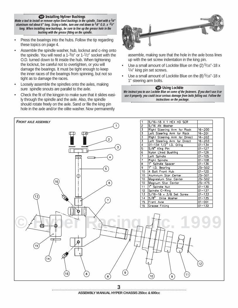
4➤ ASSEMBLE THE FRONT AXLE
• Install the nyliner bushings in the spindles. Grease the fourgrease fittings in the spindles with a grease gun.
TIP
TIP
TIP
• drill• drill bits: 13/32”, 9/32”, 3/16”,
.128• taps: 7/16”-20, 7/16”-14,
3/8”-24, 5/16”-24• Permatex Locktite Blue• teflon plumbers tape• Mystic JT-6 or other water-
proof high temp grease• grease gun
• sockets• wrenches: regular and allen• screwdrivers• cutting oil• pop rivet gun• die grinder• rubber mallet• utility knife• vice• tape measure
RACK BOX RADIUS RODS
Follow the chart on page 18 tomeasure your axle.Length Left Right34” 03-130 03-140343/4” 03-1375 03-140351/4” 03-1375 03-145361/4” 03-140 03-150371/4” 03-015 03-016
© Hyper Racing Inc. 1999
3ASSEMBLY MANUAL HYPER CHASSIS 250cc & 600cc
Installing Nyliner BushingsMake a tool to install or remove nylon lined bushings in the spindle. Start with a 3/4”aluminum rod about 6” long. Using a lathe, turn one end down to 5/8” O.D. x 3/4”
long. When installing new bushings, be sure to line up the grease hole in the bushing with the grease fitting on the spindle.
• Press the bearings into the hubs. Follow the tip regardingthese topics on page 4.
• Assemble the spindle washer, hub, locknut and c-ring ontothe spindle. You will need a 1-3/8” or 1-1/2” socket with theO.D. turned down to fit inside the hub. When tighteningthe locknut, be careful not to overtighten, or you will damage the bearings. It must be tight enough to keep the inner races of the bearings from spinning, but not sotight as to damage the races.
• Loosely assemble the spindles onto the axles, makingsure spindle snouts are parallel to the axle.
• Check the fit of the kingpin to make sure that it slides easi-ly through the spindle and the axle. Also, the spindleshould rotate freely on the axle. Sand or file the king pinhole in the axle and/or the oilite washer. Now permanently
assemble, making sure that the hole in the axle boss linesup with the set screw indentation in the king pin.
• Use a small amount of Locktite Blue on the (2) 5/16”-18 x1/4” king pin set screws.
• Use a small amount of Locktite Blue on the (8) 5/16”-18 x1” steering arm bolts.
Using LocktiteWe instruct you to use Locktite Blue on some of the fasteners. If you don’t use it oruse it properly, you could incur serious damage from bolts falling out. Follow the
instructions on the package.
FRONT AXLE ASSEMBLY
TIP
TIP

© Hyper Racing Inc. 1999
© Hyper Racing Inc. 1999
4ASSEMBLY MANUAL HYPER CHASSIS 250cc & 600cc
5➤ ASSEMBLE THE REAR AXLE
Note: The drawing on page 5 shows the spacing for the ’99and up splined rear axle with machined shoulder. If you areusing the ’94-’98 axle with snap rings and snap ring locks,consult Hyper Racing for a spacing diagram.
• Install the brake rotor onto the brake hub using a smallamount of Locktite Blue on the (4) brake rotor bolts 5/16”-18 x 3/4”.
• Install the sprocket guide hardware and sprocket guidesonto the sprocket carrier. If you know what rear sprocketyou want to run, you may put it on now or wait until youinstall the chain and engine.
• Install the bearings into the bearing carriers following thetip below. Note: In chassis kits, the bearings may bepressed in for you, but you will still need to repack themwith grease.
Increasing Bearing Life Repack all bearings, whether brand new or used, with a good quality grease beforeuse. Using a small screwdriver, remove the bearing seal. Scoop out the thin greaseused by the manufacturer and repack with Mystic JT-6 (77-300) or other waterproof
high temp grease. Repack often for best performance.
Pressing BearingsPress on the outside race of the bearings only. Pressing on the inner race will dam-
age the balls and races of the bearings.
SPROCKET GUIDE AND CARRIER ASSEMBLY
• The shoulder (widest part) of the bearing reducer in eachbearing carrier points to the left side of the chassis.
• The 3/4” O.D. 3/8” I.D. X .180” long spacer will be usedbetween the brake caliper and double bearing carrier instep 30. This spacer will align the caliper to the rotor.
• Note: When using the magnesium star or the old stylemagnum centers, remove the 3/4” spacer behind the wheelcenter.
TIP
TIP
TIP Smart AssemblyUse cutting oil to prolong the life of your drill bits.

© Hyper Racing Inc. 1999
© Hyper Racing Inc. 1999
5ASSEMBLY MANUAL HYPER CHASSIS 250cc & 600cc
REAR AXLE ASSEMBLY 250CCLEFT SIDE
REAR AXLE ASSEMBLY 250CCRIGHT SIDE
© Hyper Racing Inc. 1999
© Hyper Racing Inc. 1999
REAR AXLE ASSEMBLY 600CCLEFT SIDE
REAR AXLE ASSEMBLY 600CCRIGHT SIDE

© Hyper Racing Inc. 1999
6➤ INSTALL THE UPPER STEERING SHAFT
• Insert the two plastic bushings into the tube ends. • Apply grease to the upper steering shaft. • Install the shaft. • Install the snap ring into the groove in the shaft.7➤ INSTALL THE STEERING WHEEL TO THE QUICK RELEASE
• Use a small amount of Locktite Blue on the (3) 5/16-18 x 3/4” steering wheel to hub bolts.
6ASSEMBLY MANUAL HYPER CHASSIS 250cc & 600cc
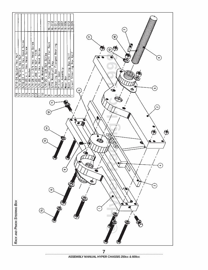
8➤ FIT THE RACK AND PINION STEERING BOX
• Slide one of the flanged bearings onto the shaft.• Push the 3/16” key into the key way of the shaft using a
vise.• Slide one box half over the key• Tap the pinion gear onto the shaft and part way onto the
key using a rubber mallet• Install this assembly into the car and slide the splined
universal onto the upper steering shaft, making sure theuniversal is slid the entire way on.
• Line up the universal joint bolt with the flat cut in the uppershaft. Tighten until snug.
• Clamp the box half to the mounting tabs on the chassis,aligning the bolt holes.
• Check the position of the gear relative to the box half. Youshould be able to slide a single piece of paper betweenthe box half and the pinion gear. Remove the shaft fromthe car and tap the gear to move it on the shaft until prop-er fit is achieved.
• Tighten the set screw in the pinion gear to the key onceyou have the position set.
• Use a waterproof grease to grease the entire surface ofthe wear plate, pinion gear, rack gear and insides of thebox halves.
• Assemble the steering box, installing the three 1/4”-20 x 1”bolts first.
• Then loosely install the bolts of the flanged bearings.
UPPER STEERING SHAFT
9➤ INSTALL THE RACK AND PINION STEERING BOX
• Hold steering box in position, and place universal ontoupper steering shaft making sure that the lock bolt lines up with the flat in the upper shaft.
• Bolt the steering box into place• Tighten the lock bolt in the universal and Locktite it in
place.Note: If there is a set screw in the universal, remove it andreplace it a 5/16-18 x 3/4” HHCS and jam nut. Locktite it inplace.• The pinion gear and flanged bearings will move up and
down in the box, allowing you to adjust play.• Hold the pinion gear down tight against the rack by push-
ing on the shaft and bearings• Tap the shaft and gear up 1/16” to prevent any binds.• Tighten all bolts to a race ready condition. Remember to
tighten the set screws on the flanged bearings to the shaft.10➤ INSTALL THE DZUS SPRINGS
• You may have to run a .128” drill bit through holes in thedzus plates to remove powder coating or paint. Thisallows the pop rivets to be installed easily.
• Use 1/8” x 1/4” pop rivets with steel mandrel. (Bag 17)Install so that the head of the pop rivet is on the outside ofthe dzus tab.
© H
yper
Rac
ing
Inc.
1999
7ASSEMBLY MANUAL HYPER CHASSIS 250cc & 600cc
RAC
KAN
DPI
NIO
NST
EER
ING
BO
X

© Hyper Racing Inc. 1999
11➤ PREPARE THE THREADED BOSSES
Run a tap through the threaded frame bosses. This allowsbolts to be installed easily. Use cutting oil when tapping thebosses to keep the taps sharp and cutting freely. The dimensions are as follows:• 3/8”-24 (2) throttle and brake pedal bosses• 3/8”-24 (2) front shock tower• 3/8”-24 (4) seat bar• 7/16”-14 (1) engine jacking bolt• 5/16”-24 (2) panhard adjuster handle bosses• 7/16”-20 all others12➤ INSTALL THE BELLY PAN
Place the large fender washer and the button head screw onoutside of belly pan. All 250cc Hyper Chassis Frames aremade to accommodate a front mount radiator. If you use arear mount radiator on the 250cc, the belly pan will extend upto the top front frame member. The front part of the belly panwill be connected to the frame with wire ties. Drill six 1/4”holes across the front edge of the belly pan and run the tiesthrough the holes and around the frame member. Note: On 600cc, use an AN washer on the top belly paninstead of the fender washer.
• Install the remote inlet adapter onto the master cylinderwith one of the clamps. Avoid breaking the master cylindero-ring by applying grease to the master cylinder o-ring andwarming the remote adapter in hot water.
• Mount the remote mounting bracket onto the chassis.Install the 4 oz. reservoir onto the remote bracket with theother clamp. Do not over tighten the clamps or the plasticmay crack.
• Remove the rubber boot from the cylinder. Fill the areainside the cylinder that is covered by the boot with grease.This will help keep the bore and piston from corroding.
• Bolt the master cylinder to the frame.• Replace the rubber boot.• Connect the reservoir to the master cylinder with 3/8” poly-
braid. Use two small hose clamps to secure the hose.• Screw the 5/16” female rod end and jam nut onto threaded
rod of the master cylinder. This rod may be cut shorter ifyou want the pedal further front.
• Slide the brake line through the brake line casing. Usespray lubricant on the brake line if the fit is tight.
• Place the 3/16” tube insert inside the 3/16” brake line, theninstall the nut and ferrule.
• Run brake line back to the caliper and let it hang for now.
Using Plastic Brake LineCopper tube inserts keep plastic line from crushing as you tighten the nut and ferrule.To use a nut and ferrule, slide the nut and ferrule over the brake line. Push the brakeline and tube insert inside the fitting. tighten the nut and ferrule on the fitting while
making sure the brake line is pushed in the fitting as far as possible.
8ASSEMBLY MANUAL HYPER CHASSIS 250cc & 600cc
TIP
TIP
13➤ INSTALL THE MASTER CYLINDER AND RESERVOIR
• Wilwood taps the end of master cylinder with a 3/8”threaded hole. You will retap the hole for 1/8” NPT. This willalready be done for you on new chassis kits.
• Screw the 90° brake fitting into the end of the mastercylinder using teflon tape. Turn the fitting so the brake linewill feed off to the right side of the master cylinder.
Using Teflon TapeWrap a single thickness of tape around the fitting, pull tape taut,
so that it forms to the threads of the fitting. The ends of the tape should overlap by about 1/4”. The tape should cover the threads, but not exceed them,
or pieces can break off and clog lines.
BELLY PAN BOLTS

© Hyper Racing Inc. 1999
© Hyper Racing Inc. 1999
9ASSEMBLY MANUAL HYPER CHASSIS 250cc & 600cc
14➤ INSTALL PEDALS
• Put grease on the bolt so that the pedal rotates freely. • Don’t tighten the bolt so much that pedal doesn’t move. • Tighten flanged nut against boss while holding the bolt
head with a wrench.15➤ INSTALL THROTTLE PULL ROD ASSEMBLY
• The end of the pull rod may be bent in a vice in order toachieve perfect match up with the pedal if necessary.
16➤ INSTALL THE THROTTLE CABLE
• Hook the end of the cable through the slot in the pinchclamp, then slide them onto the end of the shaft.
• The throttle stops will be set after the engine is installed.
PEDALS
THROTTLE PULL ROD ASSEMBLY
17➤ INSTALL SEAT BELTS
• Follow the seat belt manufacturer’s instructions for fasten-ing seat belt to chassis.
• Lap belts wrap around the vertical 11/8” tube behind theseat.
• On 94-98 chassis, the sub belt wraps around the lowerseat bar. On 1999 and newer chassis, the sub belt boltsonto the tab on the lower seat bar. This belt must beadjusted before the seat is bolted in place.
• Shoulder belts wrap around the upper horizontal framemember that the seat bolts to.
© Hyper Racing Inc. 1999
18➤ INSTALL RIGHT SIDE BODY PANEL
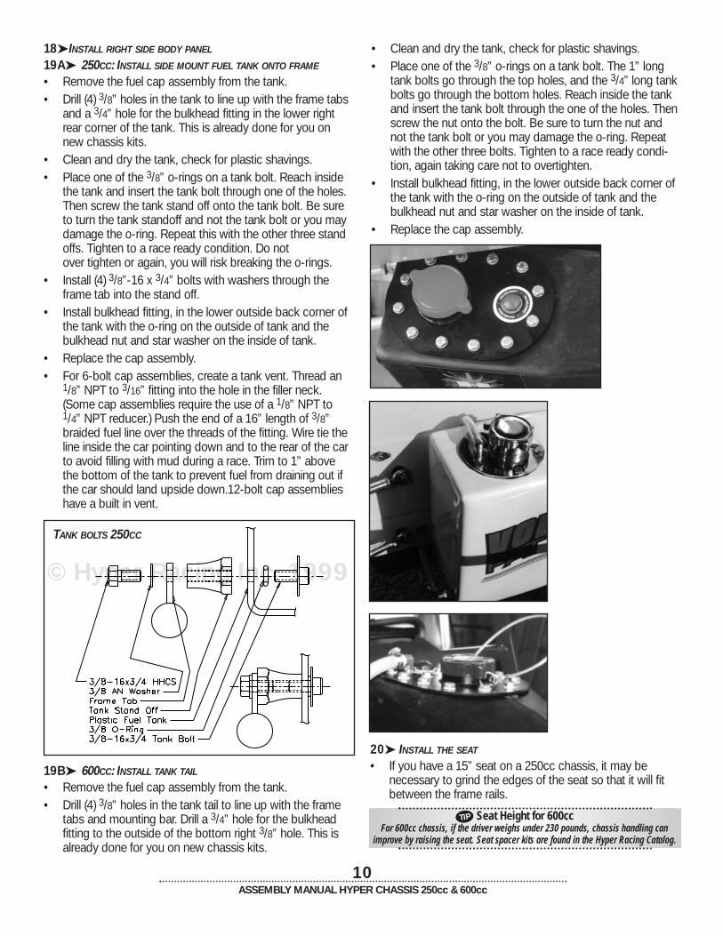
19A➤ 250CC: INSTALL SIDE MOUNT FUEL TANK ONTO FRAME
• Remove the fuel cap assembly from the tank.• Drill (4) 3/8” holes in the tank to line up with the frame tabs
and a 3/4” hole for the bulkhead fitting in the lower rightrear corner of the tank. This is already done for you onnew chassis kits.
• Clean and dry the tank, check for plastic shavings.• Place one of the 3/8” o-rings on a tank bolt. Reach inside
the tank and insert the tank bolt through one of the holes.Then screw the tank stand off onto the tank bolt. Be sureto turn the tank standoff and not the tank bolt or you maydamage the o-ring. Repeat this with the other three standoffs. Tighten to a race ready condition. Do not over tighten or again, you will risk breaking the o-rings.
• Install (4) 3/8”-16 x 3/4” bolts with washers through theframe tab into the stand off.
• Install bulkhead fitting, in the lower outside back corner ofthe tank with the o-ring on the outside of tank and thebulkhead nut and star washer on the inside of tank.
• Replace the cap assembly.• For 6-bolt cap assemblies, create a tank vent. Thread an
1/8” NPT to 3/16” fitting into the hole in the filler neck.(Some cap assemblies require the use of a 1/8” NPT to1/4” NPT reducer.) Push the end of a 16” length of 3/8”braided fuel line over the threads of the fitting. Wire tie theline inside the car pointing down and to the rear of the carto avoid filling with mud during a race. Trim to 1” abovethe bottom of the tank to prevent fuel from draining out ifthe car should land upside down.12-bolt cap assemblieshave a built in vent.
10ASSEMBLY MANUAL HYPER CHASSIS 250cc & 600cc
TANK BOLTS 250CC
• Clean and dry the tank, check for plastic shavings.• Place one of the 3/8” o-rings on a tank bolt. The 1” long
tank bolts go through the top holes, and the 3/4” long tankbolts go through the bottom holes. Reach inside the tankand insert the tank bolt through the one of the holes. Thenscrew the nut onto the bolt. Be sure to turn the nut andnot the tank bolt or you may damage the o-ring. Repeatwith the other three bolts. Tighten to a race ready condi-tion, again taking care not to overtighten.
• Install bulkhead fitting, in the lower outside back corner ofthe tank with the o-ring on the outside of tank and thebulkhead nut and star washer on the inside of tank.
• Replace the cap assembly.
TIP
19B➤ 600CC: INSTALL TANK TAIL
• Remove the fuel cap assembly from the tank.• Drill (4) 3/8” holes in the tank tail to line up with the frame
tabs and mounting bar. Drill a 3/4” hole for the bulkheadfitting to the outside of the bottom right 3/8” hole. This isalready done for you on new chassis kits.
20➤ INSTALL THE SEAT
• If you have a 15” seat on a 250cc chassis, it may be necessary to grind the edges of the seat so that it will fitbetween the frame rails.
Seat Height for 600ccFor 600cc chassis, if the driver weighs under 230 pounds, chassis handling can
improve by raising the seat. Seat spacer kits are found in the Hyper Racing Catalog.

• Place the seat into the chassis. For 600cc, if using thespacer kit, spacer between the lower seat bar and theseat.The seat should be installed at an angle so the tabs inback are sitting flat against the seat. Angle seat up ordown slightly from this for driver comfort.
• Drill the holes to mount the seat and a drain hole. Do notmake all four bolt holes at once. Do them two at a time.
• Make a mark through the top two tabs for drilling the firsttwo holes. Drill the holes using a 13/32” drill bit. Then putthe seat back in the chassis and put bolts through theholes to keep the seat in place while you mark the othertwo holes. Also mark the lowest point of the seat for awater drain hole.
• Remove the seat and drill the remaining two holes and the13/32” drain hole. The drain hole lets the water out whenyou wash the car.
• Reinstall and bolt in place using the large washers on the inside of the seat. Use grease in the threads of the lowerseat bolts to help prevent rusting
• Install the seat cover• Sit in the seat and make any necessary alterations to the
padding. You may bend the seat rib supports in or out, orthe head rest back or front. Then adjust the remaining fourseat belts, cut off the excess belt material and burn edgesto keep them from fraying.
Seat Comfort vs. Seat SafetyIt would be nice to feel comfortable in your seat as you race. But you definetly won’tbe thinking that in an accident. You should feel tight in your seat. Before drilling anyholes in your seat, try sitting in it with your racing suit on. The padding in the Kirkeyseats is very thick. Keep in mind that the padding in the seat will flatten slightly over
time. If you feel your seat is too tight, you can cut away some or all of the foampadding until the seat fits properly. Bend the aluminum wraps to fit your ribs and
hips. If your seat is too loose, exchange it for a smaller size.
24➤ FASTEN THE SHOCKS TO THE FRAME
Use the two 1/2” to 7/16” reducers on the rear shocks.Shoulders of the reducers point toward the frame.
11ASSEMBLY MANUAL HYPER CHASSIS 250cc & 600cc
© Hyper Racing Inc. 1999
TIP
SEAT BOLTS
21➤ 250CC: INSTALL LEFT FRONT AND LEFT REAR SIDE PANELS
22➤ INSTALL FIREWALL
On 250cc, it may be necessary to trim the firewall if it hits thelower frame rail.23➤ ASSEMBLE THE SHOCKS, SPRINGS AND COIL OVER KITS
Refer to the directions in the coil over kit and consult the Set-Up and Handling section of this book for shock andspring combinations.
25➤ INSTALL THE FRONT PANHARD BAR PINCH CLAMP
• Mount the front panhard bar on the front panhard barpinch clamp
• Clamp the panhard bar pinch clamp to the frame member
26➤ INSTALL THE FRONT AXLE ASSEMBLY
• Use the two 1/2” to 3/8” reducers on the bottom of thefront shocks as you mount them to the axle. Face thereducers towards the axle.
• Use two of the 7/16” aluminum rod end spacers to mountthe steering rods to the steering arms, the steering rodsget mounted underneath the steering arms.
• Bolt the front panhard bar to the axle.• Bolt the front radius rods to the axle.27➤ FRONT CONTROL ARMS TO FRAME
• Use Locktite Blue on the (3) 7/16”-20 x 11/4” bolts (controlarm to frame).
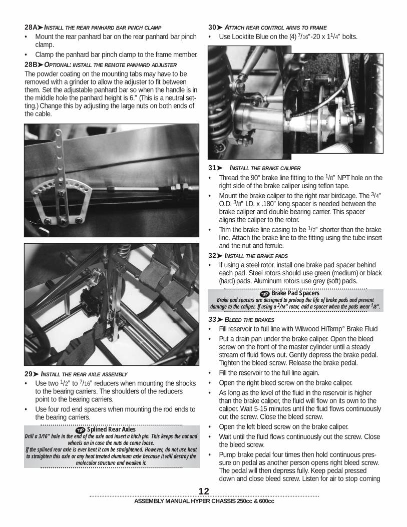
28A➤ INSTALL THE REAR PANHARD BAR PINCH CLAMP
• Mount the rear panhard bar on the rear panhard bar pinchclamp.
• Clamp the panhard bar pinch clamp to the frame member.28B➤ OPTIONAL: INSTALL THE REMOTE PANHARD ADJUSTER
The powder coating on the mounting tabs may have to beremoved with a grinder to allow the adjuster to fit betweenthem. Set the adjustable panhard bar so when the handle is inthe middle hole the panhard height is 6.” (This is a neutral set-ting.) Change this by adjusting the large nuts on both ends ofthe cable.
12ASSEMBLY MANUAL HYPER CHASSIS 250cc & 600cc
30➤ ATTACH REAR CONTROL ARMS TO FRAME
• Use Locktite Blue on the (4) 7/16”-20 x 11/4” bolts.
TIP
TIP
31➤ INSTALL THE BRAKE CALIPER
• Thread the 90° brake line fitting to the 1/8” NPT hole on theright side of the brake caliper using teflon tape.
• Mount the brake caliper to the right rear birdcage. The 3/4”O.D. 3/8” I.D. x .180” long spacer is needed between thebrake caliper and double bearing carrier. This spaceraligns the caliper to the rotor.
• Trim the brake line casing to be 1/2” shorter than the brakeline. Attach the brake line to the fitting using the tube insertand the nut and ferrule.
32➤ INSTALL THE BRAKE PADS
• If using a steel rotor, install one brake pad spacer behindeach pad. Steel rotors should use green (medium) or black(hard) pads. Aluminum rotors use grey (soft) pads.
Brake Pad SpacersBrake pad spacers are designed to prolong the life of brake pads and prevent
damage to the caliper. If using a 3/16” rotor, add a spacer when the pads wear 1/8”.
33➤ BLEED THE BRAKES
• Fill reservoir to full line with Wilwood HiTemp° Brake Fluid• Put a drain pan under the brake caliper. Open the bleed
screw on the front of the master cylinder until a steadystream of fluid flows out. Gently depress the brake pedal.Tighten the bleed screw. Release the brake pedal.
• Fill the reservoir to the full line again.• Open the right bleed screw on the brake caliper.• As long as the level of the fluid in the reservoir is higher
than the brake caliper, the fluid will flow on its own to thecaliper. Wait 5-15 minutes until the fluid flows continuouslyout the screw. Close the bleed screw.
• Open the left bleed screw on the brake caliper.• Wait until the fluid flows continuously out the screw. Close
the bleed screw.• Pump brake pedal four times then hold continuous pres-
sure on pedal as another person opens right bleed screw.The pedal will then depress fully. Keep pedal presseddown and close bleed screw. Listen for air to stop coming
29➤ INSTALL THE REAR AXLE ASSEMBLY
• Use two 1/2” to 7/16” reducers when mounting the shocksto the bearing carriers. The shoulders of the reducerspoint to the bearing carriers.
• Use four rod end spacers when mounting the rod ends tothe bearing carriers.
Splined Rear AxlesDrill a 3/16” hole in the end of the axle and insert a hitch pin. This keeps the nut and
wheels on in case the nuts do come loose.If the splined rear axle is ever bent it can be straightened. However, do not use heatto straighten this axle or any heat treated aluminum axle because it will destroy the
molecular structure and weaken it.

© Hyper Racing Inc. 1999
13ASSEMBLY MANUAL HYPER CHASSIS 250cc & 600cc
out of the bleed screw. Repeat this procedure until no air ispresent in the brake lines.
• Repeat above procedure while opening the left bleedscrew. Make sure the level of brake fluid in the reservoirstays above the minimum line.
• Fill reservoir to the maximum line. • Tighten all bleed screws and reservoir cap to a race ready
condition.34➤ INSTALL THE SHIFTER
• Mount the shifter handle to the frame.• Run the shifter cable around the rack box and out the left
side.• Remove one large nut from the cable. If your cable had
star lock washers on it, remove and discard them. Run thecable through the tab and replace the nut.
• Screw the jam nut and rod end onto the end of the cable.• Bolt the rod end to the handle.
TIP
35A➤ 250CC: INSTALL THE FRONT MOUNT RADIATOR
• The flex mount system is designed to hold the radiator onfour rubber covered posts.
• Lay the tray down on the frame.• Create the posts by pushing the bolts up through the bot-
tom of the tab and tray and secure them with the washersand nuts.
• If the radiator tabs do not have holes, line the radiator tabsup over the bolts and gently tap each of the four tabs witha hammer to mark the holes. Drill a 9/16” hole in each tab.
• Slide the rubber grommet over the top of the nuts andthen push the lengths of hose over the bolts.
• Mount the radiator over all four posts.Note: Never mount a radiator solid or without rubber or it willcrack and leak.
Easy Does ItRemove air bubbles from the radiator and hoses by lifting it out off the posts andmoving it around. 2”-4” of air will appear in the lines at each end of the reservoir
after a race. This is caused by the expansion of the hot water and it is normal. If youare losing more water than this, one of the following may be the cause: a leak in the
coolant system, blown head gasket, or blown head o-rings. If you can eliminatethese causes and still have the problem, try a 16-21 lb. radiator cap.
250CC FRONT MOUNT RADIATOR
35B➤ 600CC: INSTALL THE REAR MOUNT RADIATOR
• Install the fittings into the radiator using an elbow fitting onthe top and a straight fitting on the bottom.
• Place one rubber grommet in the top tab of the radiator.For ’98 and up, place the other two grommets below theradiator in the aluminum angle bracket. On ’95-’98, placethe two grommets in the frame tab.
• Place the two posts through the grommets in the bracket.• Use a 3/8”-24 x 1” bolt with two AN washers and a nylock
half nut to hold the top of the radiator to the frame.

© Hyper Racing Inc. 1999
© Hyper Racing Inc. 1999© Hyper Racing Inc. 1999
© Hyper Racing Inc. 1999© Hyper Racing Inc. 1999
REAR WHEEL
14ASSEMBLY MANUAL HYPER CHASSIS 250cc & 600cc
FRONT WHEEL

15ASSEMBLY MANUAL HYPER CHASSIS 250cc & 600cc
TIP
TIP
37➤ MOUNT THE TIRES ONTO THE WHEELS
• Select the tire sizes, compounds and pressure best foryour typical track size and conditions.
38➤ MOUNT THE WHEELS ONTO THE AXLES
• Use a 1” diameter x 4’ bar in conjunction with the 1.9”socket to tighten the splined rear axle nuts.
39➤ BOLT ON THE BUMPERS AND NERF BARS
Don’t overtighten the bumper and nerf bar bolts or you willdeform the socket.40➤ MOUNT THE HOOD AND 250CC TAIL
41➤ MOUNT THE REAR WING UPRIGHT AND WING
• Drill 7/32” holes in the wing posts. See drawing on page 16.• Bolt the wing to the runners so the wing is in the hole
closest to the front.• Tighten the bolt just enough to pinch the rear wing upright.
Then tighten the nut against the pinch clamp to keep thebolt from loosening.
42➤ INSTALL THE MANUAL WING ADJUSTER
• Remove the handle from the cable and the nut with the o-ring.• Insert the push-pull end of the cable through the frame tab
in the cockpit.• Screw on the nut with the o-ring until it is tight on the
housing but not tight against the tab.• Tighten the back nut up against the tab.
• Replace the handle and use locktite on the small screw orthe handle will fall off.
• Insert the other end of the cable throught the tab on theright side of the front wing upright.
• Screw the 1/4” jam nut and female rod end all the way onthe threaded rod. Tighten the jam nut against the rod end.
• Move the wing fully front.• Pull the handle in the cockpit until it is entirely out (about 6”)• Hold the rod end up to the wing runner. If there is no hole
within 1/2”, drill a 9/32” hole in an appropriate position.• The cable must be preloaded to keep the wing from
moving while you race. Rotate the rod end 21/2” to 3”turns clockwise.Then bolt the rod end to the wing runner.
Note: Now that the cable is preloaded, the handle in the cockpit can only be turned clockwise to unlock the handle.Once you move the wing into the desired position, only a lightcounter clockwise twist is required to lock the wing in place.
36➤ ASSEMBLE THE WHEELS
• Front wheel centers require four of the holes in the wheelhalves to be drilled out to 11/32”.
• File or grind the halves so that they slide on and off thestar centers easily.
Using SiliconeUse 100% silicone to seal the two halves together. Apply a bead around the entire
seam, then use a piece of cardboard as a squeegee to smooth it out.
• If the outside half did not come with a valve stem hole, drilla 7/16” hole through the outside half. On the front wheels,do not to line up the valve stem with the lug nut hole.
Tech TalkThe size of the inner half is referred to as the wheel’s“offset” or “backspacing.” For example, the right rear wheel is called 6” on 4” or 10” with 4” backspacing.
wheel half sizesOuter Half Inner Half
250cc Left Front 3” 3”600cc Left Front 4” 3”250cc Right Front 3” 3”600cc Right Front 3” 4”250cc Left Rear 5” 3”600cc Left Rear 6” 4”250cc, 600cc Right Rear 6” 4”
KNOW THE CODE
© Hyper Racing Inc. 1999
REAR WINGPINCH CLAMP
© Hyper Racing Inc. 1999
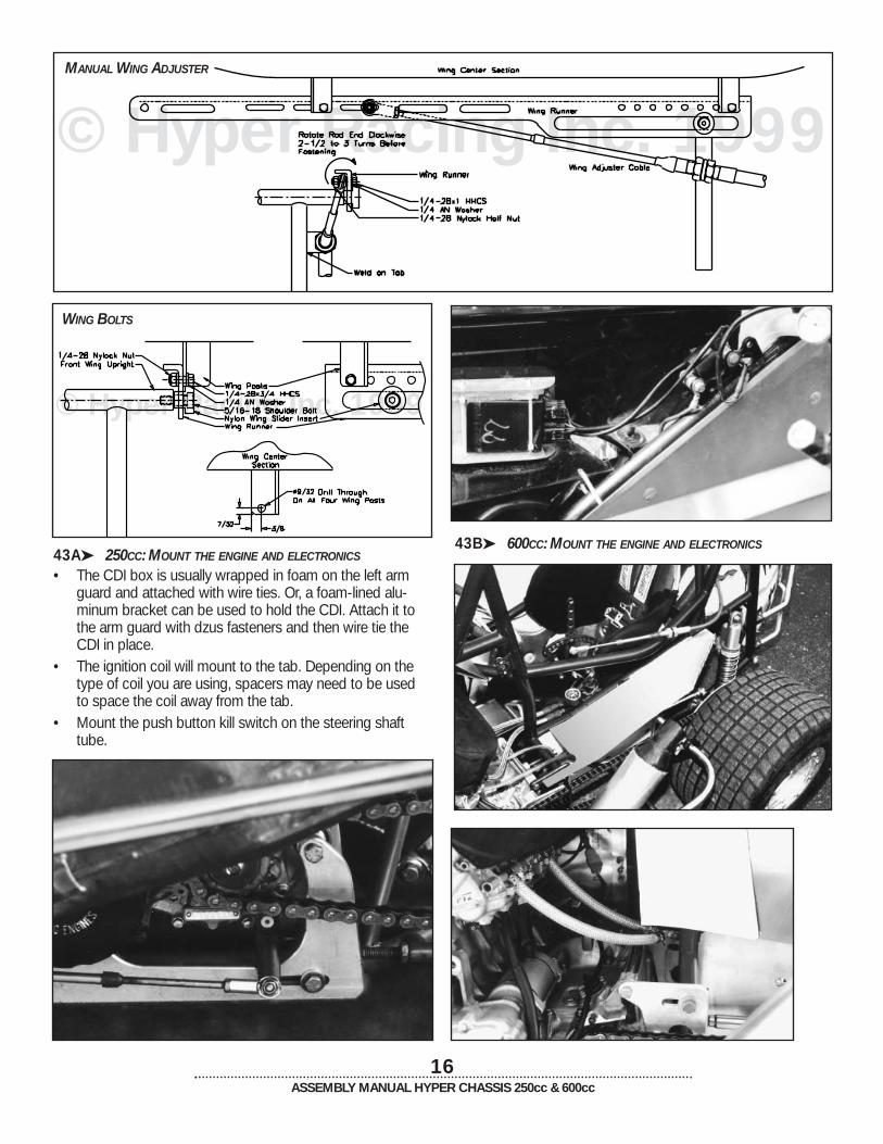
43B➤ 600CC: MOUNT THE ENGINE AND ELECTRONICS
16ASSEMBLY MANUAL HYPER CHASSIS 250cc & 600cc
43A➤ 250CC: MOUNT THE ENGINE AND ELECTRONICS
• The CDI box is usually wrapped in foam on the left armguard and attached with wire ties. Or, a foam-lined alu-minum bracket can be used to hold the CDI. Attach it tothe arm guard with dzus fasteners and then wire tie theCDI in place.
• The ignition coil will mount to the tab. Depending on thetype of coil you are using, spacers may need to be usedto space the coil away from the tab.
• Mount the push button kill switch on the steering shafttube.
© Hyper Racing Inc. 1999MANUAL WING ADJUSTER
WING BOLTS

17ASSEMBLY MANUAL HYPER CHASSIS 250cc & 600cc
44➤ ADJUST THE THROTTLE STOPS
• The driver must be able to press as hard as he wants onthe pedal and not stretch, frey or damage the throttlecable. In order for this to happen, the spring on the pullrod assembly must bottom out before the throttle valve inthe carburetor tops out. While this happens, the throttlevalve must be fully open.
• Install the throttle cable into the carb and onto the pull rod• Hold the throttle pedal in the return position. Slide the
return stop up against the frame tab and tighten.• Slide the spring and its pinch clamp up to the tab. Hold
the pedal fully returned while continuing to slide thespring’s pinch clamp 3/8” and tighten. This will put a pre-load on the spring.
• Adjust the cable adjuster on top of the carburetor untilthere are 3/16” of threads exposed above the jam nut.
• With the throttle valve in the carburetor in the closed posi-tion, slide the throttle cable pinch clamp front on the pullrod just until there is no slack in the throttle cable, tightenpinch clamp.
• Press throttle pedal until either the spring becomes fullycompressed or the throttle valve tops out in the carb.
• If the throttle valve tops out, then try one of the following:turn carburetor cable adjuster down, move cable pinchclamp back on pull rod or add more preload on spring bysliding spring pinch clamp forward on pull rod.
• If the spring bottoms out first check to see if throttle valveis fully open (not hanging down in carb at all). If it is notfully open then screw cable adjuster up out of the carbure-tor, slide spring pinch clamp back on pull rod (but makesure there is still some preload on the spring) or slide cablepinch clamp forward on pull rod (but without openingthrottle valve when pedal is in return position). If spring isbottomed out and throttle valve is opened entirely thenyou have correctly adjusted the throttle stops.
• Check to make sure you are getting full throttle each weekduring your weekly maintenance. You can apply spraylubricant on the throttle cable each week to help it lastlonger.
• When finished, make sure that at full throttle the throttlepedal does not hit the steering rods or rack system. If itdoes it will cause the steering to lock and the throttle tostay on full.

© Hyper Racing Inc. 1999
© Hyper Racing Inc. 1999
18ASSEMBLY MANUAL HYPER CHASSIS 250cc & 600cc
45A➤ 250CC: INSTALL THE PIPE AND PIPE SUPPORT SYSTEM
Increase the diameter of the 250cc pipe cradle saddle bysqueezing it in a vice to achieve proper fit.
250CC PIPE SUPPORT SYSTEM
45B➤ 600CC: INSTALL THE PIPE AND PIPE SUPPORT SYSTEM