2007 and up hyper chassis 600cc assembly … and up hyper chassis 600cc assembly manual hyper racing...
TRANSCRIPT

2007 AND UPHYPER CHASSIS 600CC
ASSEMBLY MANUAL
HYPER RACING580A GRANDVIEW DRIVELEWISBERRY, PA 17339
TEL (717) 938-8732FAX (717) 938-8521
www.hyperracing.com

HYPER CHASSIS 600cc ASSEMBLY GUIDE 2
About This ManualThis manual is based on our experience assembling over 100 chassis. Follow the steps in order for maximum effi ciency.
PreparationRead the entire procedure.Familiarize yourself with all hardware kits and parts.The following tools and materials will be needed:• bolts list found at the end of this manual• drill• drill bits: 13/32”, 9/32”, 3/16”, .128• taps: 7/16”-20, 7/16”-14, 3/8”-24, 5/16”-24• Permatex Locktite Blue• tefl on plumbers tape• Mystic JT-6 or waterproof, lightweight, high temp grease• grease gun• sockets• wrenches: regular and allen• screwdrivers• cutting oil• pop rivet gun• die grinder• rubber mallet• utility knife• vice• tape measure
SMART ASSEMBLYWhen assembling the chassis at the shop, we put the most of
the chassis together “loosely assembled” with the exception of bolts that are hard to reach at a later time, such as the fuel tank
mount to frame. Once the entire chassis is assembled, tighten to race ready condition.
HYPER CHASSIS 600cc ASSEMBLY MANUAL 3
Procedure
1 Drill holes in bumpers, nerf bars, injector protector bar and front wing upright• Mark the ends of the tubes 1” from the end so that you can tell when they are in the entire way. Sometimes you will have to open up the socket with a die grinder to remove paint or powder coating. Use a rubber mallet or a hammer and a block of wood against the rail and push the rails into the sockets up to your mark. • Drill through the existing holes in the sockets all the way through the rails with a 3/16” drill bit. • Remove nerf bars and bumpers and set aside until the end.• If using an electronic wing adjuster, slide on the pinch clamp onto the front wing upright. Bolt the front wing upright and front and rear bumpers in place.
SMART ASSEMBLYTo avoid scratching the sheet metal, follow this sequence. Drill the bolt holes in the nerf bars, bumpers, and front wing upright
before the sheet metal is fi tted. Then fi t the unpainted sheet metal. Have the sheet metal painted while you start the rest of
your assembly.
2 Fit the body panels to the frame. In chassis kits, this step is done for you. To fi t a new body panel, use your old one as a guide to mark the holes.
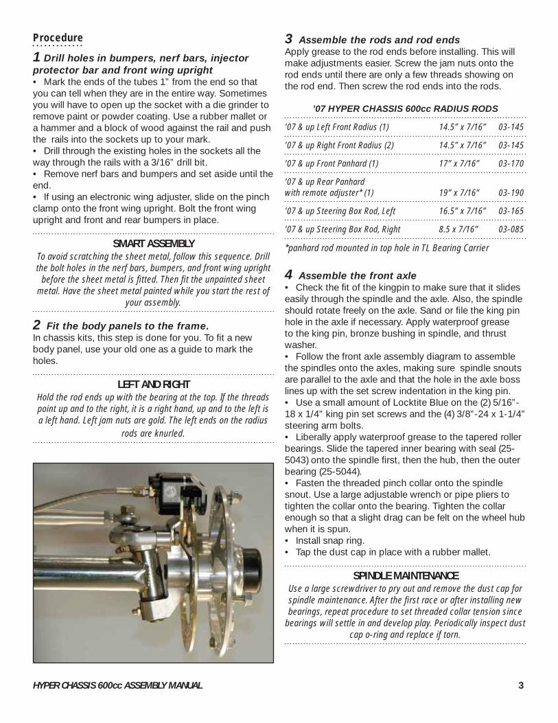
LEFT AND RIGHTHold the rod ends up with the bearing at the top. If the threads point up and to the right, it is a right hand, up and to the left is a left hand. Left jam nuts are gold. The left ends on the radius
rods are knurled.
3 Assemble the rods and rod endsApply grease to the rod ends before installing. This will make adjustments easier. Screw the jam nuts onto the rod ends until there are only a few threads showing on the rod end. Then screw the rod ends into the rods.
’07 HYPER CHASSIS 600cc RADIUS RODS
’07 & up Left Front Radius (1) 14.5” x 7/16” 03-145
’07 & up Right Front Radius (2) 14.5” x 7/16” 03-145
’07 & up Front Panhard (1) 17” x 7/16” 03-170
’07 & up Rear Panhard with remote adjuster* (1) 19” x 7/16” 03-190
’07 & up Steering Box Rod, Left 16.5” x 7/16” 03-165
’07 & up Steering Box Rod, Right 8.5 x 7/16” 03-085
*panhard rod mounted in top hole in TL Bearing Carrier
4 Assemble the front axle• Check the fi t of the kingpin to make sure that it slides easily through the spindle and the axle. Also, the spindle should rotate freely on the axle. Sand or fi le the king pin hole in the axle if necessary. Apply waterproof grease to the king pin, bronze bushing in spindle, and thrust washer. • Follow the front axle assembly diagram to assemble the spindles onto the axles, making sure spindle snouts are parallel to the axle and that the hole in the axle boss lines up with the set screw indentation in the king pin. • Use a small amount of Locktite Blue on the (2) 5/16”-18 x 1/4” king pin set screws and the (4) 3/8”-24 x 1-1/4” steering arm bolts.• Liberally apply waterproof grease to the tapered roller bearings. Slide the tapered inner bearing with seal (25-5043) onto the spindle fi rst, then the hub, then the outer bearing (25-5044). • Fasten the threaded pinch collar onto the spindle snout. Use a large adjustable wrench or pipe pliers to tighten the collar onto the bearing. Tighten the collar enough so that a slight drag can be felt on the wheel hub when it is spun.• Install snap ring. • Tap the dust cap in place with a rubber mallet.
SPINDLE MAINTENANCEUse a large screwdriver to pry out and remove the dust cap for spindle maintenance. After the fi rst race or after installing new bearings, repeat procedure to set threaded collar tension since
bearings will settle in and develop play. Periodically inspect dust cap o-ring and replace if torn.

HYPER CHASSIS 600cc ASSEMBLY GUIDE 4
USING LOCKTITEUse of Locktite Blue is specifi ed on some of the fasteners. If you
don’t use it or use it improperly, serious damage could result from bolts falling out. Follow the instructions on the package.
FRONT AXLE ASSEMBLY

HYPER CHASSIS 600cc ASSEMBLY MANUAL 5
5 Assemble the rear axleNote: The rear axle assembly drawing shows the spac-ing for the ’07 and up splined rear axle with machined shoulder.• Install the brake rotor onto the brake hub using a small amount of Locktite Blue on the (4) 5/16”-18 x 3/4” brake rotor bolts.• Install the sprocket guide hardware and sprocket guides onto the sprocket carrier. If you know what rear sprocket you want to run, you may put it on now or wait until you install the chain and engine.• Install the bearings into the bearing carriers following the tip below. Note: In chassis kits, the bearings may be pressed in for you, but you will still need to repack them with grease. Add 5 pumps of waterproof, lightweight , high temp grease from a grease gun.• The shoulder (widest part) of the bearing reducer in each bearing carrier points to the left side of the chassis. • The fi rst spacer on the axle must be the internal radius style to properly fi t the radius of the axle.
PRESSING BEARINGSPress on the outside race of the bearings only. Pressing on the
inner race will damage the balls and races of the bearings.
SHOP TALK We highly recommend Mystic JT-6 (77-300) as the best waterproof, lightweight, high temp grease. Repack often
for best performance.
SPROCKET GUIDE & CARRIER ASSEMBLY
viewed from rear

HYPER CHASSIS 600cc ASSEMBLY GUIDE 6
REAR AXLE ASSEMBLY
right side
left side

HYPER CHASSIS 600cc ASSEMBLY MANUAL 7
6 Install the upper steering shaft• Insert the two plastic bushings into the tube ends. • Apply grease to the upper steering shaft. • Install the shaft. • Install the 5/8” shaft collar onto the steering shaft.• Attach the upper steering shaft to the frame using the steering shaft clamp. Roughly set the angle of the shaft, fi nal adjustment will be done after the driver is fi tted.
7 Install the steering wheel to the quick release• Use a small amount of Locktite Blue on the (3) 5/16-18 x 3/4” steering wheel to hub bolts.
8 Install the dzus springs• If necessary, run a .128” drill bit through holes in the dzus plates to remove powder coating or paint. This al-lows the pop rivets to be installed easily.• Use 1/8” x 1/4” pop rivets with steel mandrel. • Install so that the head of the pop rivet is on the outside of the dzus tab.
9 Prepare the threaded bossesRun a tap through the threaded frame bosses. This allows bolts to be installed easily. Use cutting oil when tapping the bosses to keep the taps sharp and cut-ting freely. The dimensions are as fol-lows:• 1/2”-20 (2) wishbones• 3/8”-24 (4) seat bar• 7/16”-14 (1) engine jacking bolt• 5/16”-24 (2) panhard adjuster handle bosses• 7/16”-20 all others
10 Install the belly pan & nose scoop
UPPER STEERING SHAFT

HYPER CHASSIS 600cc ASSEMBLY GUIDE 8
11 Prepare and install the pedal assembly• Tilton machines the end of master cylinder with a 3/8”-24 threaded hole. You will need to retap the hole for 1/8” NPT. • Screw the brake fi tting into the end of the master cyl-inder using tefl on tape. • Install the 4 oz. reservoir using one of the clamps. Avoid breaking the master cylinder o-ring by applying grease to the master cylinder o-ring and warming the remote adapter in hot water.• Remove the rubber boot from the cylinder. Fill the area inside the cylinder that is covered by the boot with grease. This will help keep the bore and piston from cor-roding.• Bolt the master cylinder to the pedal assembly.• Screw the 5/16” female rod end and jam nut onto threaded rod of the master cylinder.• If your pedal assembly came pre-assembled, double check the bolts to make sure they are all tight.
• Bolt the pedal assembly rails onto the frame. Position them so they are the same on both sides. If you have a short driver move them toward the seat the whole way, tall drivers do the opposite.• Bolt the pedal assembly to the pedal rails. Position for driver comfort, they can be moved later if needed.• Run brake lines to the calipers and let them hang for now.
12 Install the throttle cable• Remove one nut from the straight end of the cable. Thread the straight end of the cable through the hole in the angle bracket. Put the nut back on. Hook the end of the cable through the slot in the retainer.• The pedal stop and cable adjustments will be set after the engine is installed.
HYPER CHASSIS 600cc ASSEMBLY MANUAL 9
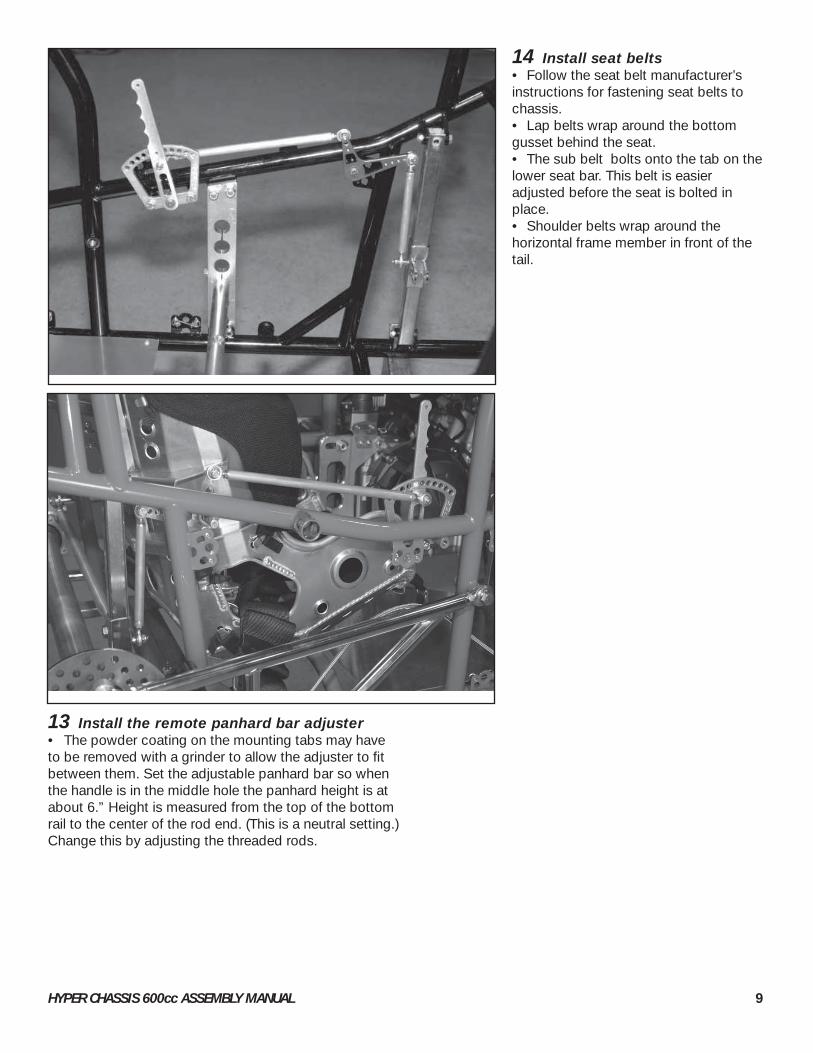
13 Install the remote panhard bar adjuster • The powder coating on the mounting tabs may have to be removed with a grinder to allow the adjuster to fi t between them. Set the adjustable panhard bar so when the handle is in the middle hole the panhard height is at about 6.” Height is measured from the top of the bottom rail to the center of the rod end. (This is a neutral setting.) Change this by adjusting the threaded rods.
14 Install seat belts• Follow the seat belt manufacturer’s instructions for fastening seat belts to chassis.• Lap belts wrap around the bottom gusset behind the seat.• The sub belt bolts onto the tab on the lower seat bar. This belt is easier adjusted before the seat is bolted in place.• Shoulder belts wrap around the horizontal frame member in front of the tail.
HYPER CHASSIS 600cc ASSEMBLY GUIDE 10
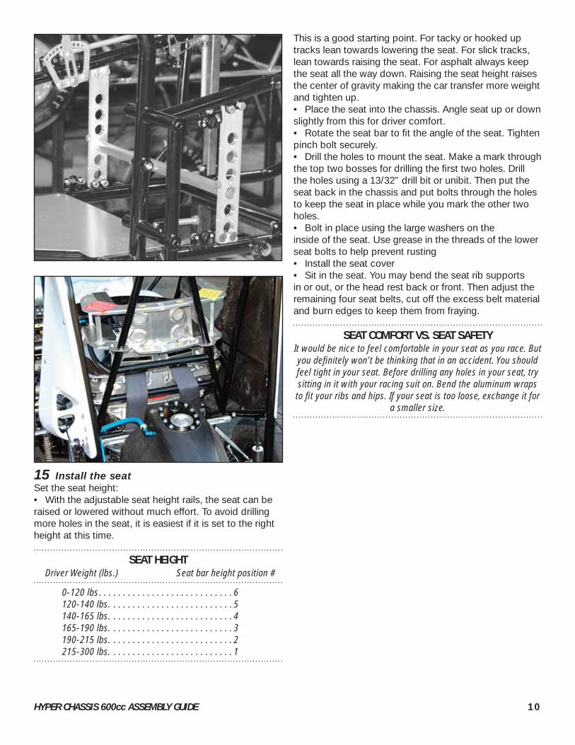
15 Install the seat Set the seat height:• With the adjustable seat height rails, the seat can be raised or lowered without much effort. To avoid drilling more holes in the seat, it is easiest if it is set to the right height at this time.
SEAT HEIGHT Driver Weight (lbs.) Seat bar height position #
0-120 lbs. . . . . . . . . . . . . . . . . . . . . . . . . . . . 6 120-140 lbs. . . . . . . . . . . . . . . . . . . . . . . . . . 5 140-165 lbs. . . . . . . . . . . . . . . . . . . . . . . . . . 4 165-190 lbs. . . . . . . . . . . . . . . . . . . . . . . . . . 3 190-215 lbs. . . . . . . . . . . . . . . . . . . . . . . . . . 2 215-300 lbs. . . . . . . . . . . . . . . . . . . . . . . . . . 1
This is a good starting point. For tacky or hooked up tracks lean towards lowering the seat. For slick tracks, lean towards raising the seat. For asphalt always keep the seat all the way down. Raising the seat height raises the center of gravity making the car transfer more weight and tighten up.• Place the seat into the chassis. Angle seat up or down slightly from this for driver comfort. • Rotate the seat bar to fi t the angle of the seat. Tighten pinch bolt securely. • Drill the holes to mount the seat. Make a mark through the top two bosses for drilling the fi rst two holes. Drill the holes using a 13/32” drill bit or unibit. Then put the seat back in the chassis and put bolts through the holes to keep the seat in place while you mark the other two holes. • Bolt in place using the large washers on the inside of the seat. Use grease in the threads of the lower seat bolts to help prevent rusting• Install the seat cover• Sit in the seat. You may bend the seat rib supports in or out, or the head rest back or front. Then adjust the remaining four seat belts, cut off the excess belt material and burn edges to keep them from fraying.
SEAT COMFORT VS. SEAT SAFETYIt would be nice to feel comfortable in your seat as you race. But you defi nitely won’t be thinking that in an accident. You should feel tight in your seat. Before drilling any holes in your seat, try sitting in it with your racing suit on. Bend the aluminum wraps to fi t your ribs and hips. If your seat is too loose, exchange it for
a smaller size.

HYPER CHASSIS 600cc ASSEMBLY MANUAL 11
16 Install tank tail• Attach the tail mounting bar.• Remove the fuel cap assembly from the tank.• Set the tail in place, height will be determined by lower tabs, rest the tail on the tabs, do not force down, then center up the top of the tail on the frame.• Mark and drill (2) 3/8” holes in the upper tank tail to line up with the tail mounting bar. Push the top two bolts in place, but do not tighten. Mark and drill (2) 5/16” holes for the lower frame tabs. Drill a 9/16” hole for the shutoff valve/bulkhead fi tting about three inches up from the lower rear torsion bar rack in the center of the tail. See graphic.
• Clean and dry the tank, check for plas-tic shavings.• Place the o-rings on a tank bolts. Reach inside the tank and insert the tank bolt through the one of the holes. Then screw the nut onto the bolt. Be sure to turn the nut and not the tank bolt or you may damage the o-ring. Repeat with the other three bolts. Tighten to a race ready condition, do not overtighten or the o-ring will squeeze out of the washer and will not seal.• Install the shutoff valve with the o-ring washer (stat-o-seal washer) on the outside of tank and the bulkhead nut and star washer on the inside of tank.• Replace the cap assembly.
TANK BOLT

HYPER CHASSIS 600cc ASSEMBLY GUIDE 12
17 Install the lower body panels and ignition panel.
18 Install the shock pins• There are 6 pins total, 4 for the frame and 2 for the rear control arms.
19 Fasten the shocks to the frame• Consult the setup sheet for locations.
20 Install the front panhard bar pinch clamp• Mount the front panhard bar on the front panhard bar pinch clamp • Clamp the panhard bar pinch clamp to the frame member• When tightening this clamp always tighten the side with the rod end on fi rst, then the small bolt second.
21 Install the front axle assembly• Use the two 1/2” to 3/8” reducers on the bottom of the front shocks as you mount them to the axle. Face the reducers towards the axle.• the steering rods get mounted underneath the steering arms.• Bolt the front panhard bar to the axle.• Bolt the front radius rods to the axle. The radius road go on the outside of the axle tabs. Use a spacer on the left front radius rod, between the rod end and the front axle tab.• Use Locktite Blue on the (3) 7/16”-20 x 1-1/4” bolts (control arm to frame).
22 Install the rear axle assembly• Use four rod end spacers when mounting the control arms to the bearing carriers.• Drill a 3/16” hole in the end of the axle and insert a hitch pin. This keeps the nut and wheels on in case the nuts do come loose.
23 Attach the rear wish bones to the frame• Use Locktite Blue on the (2) 1/2”-20 bolts.
24 Install the torsion bars• Tap in the torsion bar busings.• Ream out with a .878” pilot or torsion bar reamer.reamer. Be careful to hold the ream straight. • Blow out chips from torsion tube.• Apply grease to the torsion bar ends (where they ride on the busings) and to the inside of the bushings.• Install the torsion bars. Consult setup sheet for proper location. Always keep number of bar on the arm side. This way you will always know which way the car went in. Do not put bars in different corners of the car where it is twisted in the opposite direction. Bars must spin freely in tubes to avoid binding.• With proper size blocks under the axles (consult setup sheet), attach the torsion arms. • Attach the rear shackles to the rear torsion arms and the bearing carriers. Set the distance between the center of the two rod ends of the shackles to 3-1/8”. • Back off the torsion stop jacker bolts. Rotate the stop to the correct orientation. Attach them to the bars. Leave 1/16” to 1/8” play between the side of the stop and the bushing. When stops and arms are tight, the assembly should be able to move back and forth 1/16” to 1/8”. This will keep the bar from binding when it “winds up” under racing loads.• Final settings of the torsion stop jacker bolts will be done during fi nal setup.
HYPER CHASSIS 600cc ASSEMBLY MANUAL 13
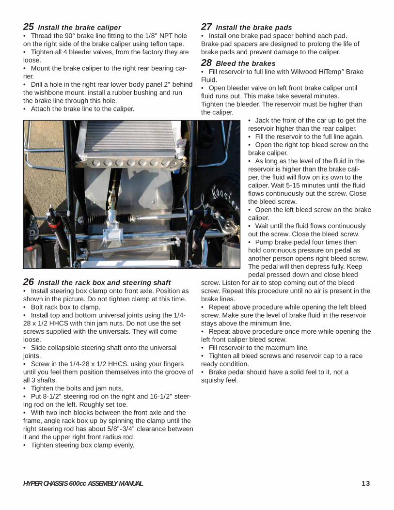
25 Install the brake caliper• Thread the 90° brake line fi tting to the 1/8” NPT hole on the right side of the brake caliper using tefl on tape.• Tighten all 4 bleeder valves, from the factory they are loose.• Mount the brake caliper to the right rear bearing car-rier. • Drill a hole in the right rear lower body panel 2” behind the wishbone mount. install a rubber bushing and run the brake line through this hole.• Attach the brake line to the caliper.
26 Install the rack box and steering shaft• Install steering box clamp onto front axle. Position as shown in the picture. Do not tighten clamp at this time.• Bolt rack box to clamp.• Install top and bottom universal joints using the 1/4-28 x 1/2 HHCS with thin jam nuts. Do not use the set screws supplied with the universals. They will come loose.• Slide collapsible steering shaft onto the universal joints.• Screw in the 1/4-28 x 1/2 HHCS. using your fi ngers until you feel them position themselves into the groove of all 3 shafts.• Tighten the bolts and jam nuts.• Put 8-1/2” steering rod on the right and 16-1/2” steer-ing rod on the left. Roughly set toe.• With two inch blocks between the front axle and the frame, angle rack box up by spinning the clamp until the right steering rod has about 5/8”-3/4” clearance between it and the upper right front radius rod.• Tighten steering box clamp evenly.
27 Install the brake pads• Install one brake pad spacer behind each pad. Brake pad spacers are designed to prolong the life of brake pads and prevent damage to the caliper.
28 Bleed the brakes• Fill reservoir to full line with Wilwood HiTemp° Brake Fluid.• Open bleeder valve on left front brake caliper until fl uid runs out. This make take several minutes. Tighten the bleeder. The reservoir must be higher than the caliper.
• Jack the front of the car up to get the reservoir higher than the rear caliper. • Fill the reservoir to the full line again.• Open the right top bleed screw on the brake caliper.• As long as the level of the fl uid in the reservoir is higher than the brake cali-per, the fl uid will fl ow on its own to the caliper. Wait 5-15 minutes until the fl uid fl ows continuously out the screw. Close the bleed screw.• Open the left bleed screw on the brake caliper.• Wait until the fl uid fl ows continuously out the screw. Close the bleed screw.• Pump brake pedal four times then hold continuous pressure on pedal as another person opens right bleed screw. The pedal will then depress fully. Keep pedal pressed down and close bleed
screw. Listen for air to stop coming out of the bleed screw. Repeat this procedure until no air is present in the brake lines.• Repeat above procedure while opening the left bleed screw. Make sure the level of brake fl uid in the reservoir stays above the minimum line. • Repeat above procedure once more while opening the left front caliper bleed screw.• Fill reservoir to the maximum line. • Tighten all bleed screws and reservoir cap to a race ready condition.• Brake pedal should have a solid feel to it, not a squishy feel.

HYPER CHASSIS 600cc ASSEMBLY GUIDE 14
29 Install the shifter• Install the shifter handle to the shifter clamp.• Mount the shifter clamp to the frame, make the handle shaft parallel to the ground. When tightening the clamp, tighten the bolts evenly, keeping the gap between the two halves even. If these are off, the handle will bind.• Attach the shifter rod.• Attach the clutch handle.• Attach the clutch cable after the engine is installed.
30 Install the front mount radiator• Install the two 90 degree fi ttings in to radiator using tefl on tape. Turn them so they are pointed back.• Install the small 90 degree fi tting in the 1/8 NPT hole near the cap using tefl on tape. Turn it so it is down and to the right. This fi tting is used as a bypass line and to help bleed air from the system.• Put two rubber bushings in the frame tabs.• Set the radiator in place, pushing the posts of the radiator through the bushings.• Bolt the mounting bracket in place.
31 Mount the rear wing upright and wing• Mount the rear wing upright to the frame.• Attach the wing runners to the uprights.• Drill 7/32” holes in the posts of the wing. See drawing.• Bolt the wing to the runners so the wing is in the second hole back. Move wing on runners front or back
based on the track. Move back more for slick tracks.• Tighten the bolt just enough to pinch the rear wing upright. Then tighten the nut against the pinch clamp to keep the bolt from loosening.

HYPER CHASSIS 600cc ASSEMBLY MANUAL 15
32 Install the electric wing adjuster
REAR WING PINCH CLAMP
WING BOLTS
ELECTRIC WING ADJUSTER ASSEMBLY

HYPER CHASSIS 600cc ASSEMBLY GUIDE 16
33 Mount the engine • Reference the engine spacer chart in the back of this manual. If your engine is not listed, please call the shop.• Put the rear plates on the engine. Do not tighten bolts at this time, leave them very loose.• Bolt the upper right front engine mount to the frame.• Set engine in the car, put in the two 8” long 7/16” bolts fi rst, then the front bolt.• Make sure engine is setting in the car level and square.
34 Mount the electronics• Connect the harness to the engine.• Run the wires through the ignition panel.• Mount the electronics. Layout the electronic components while they are connected to the harness. • Drill holes in dash for switches and gages. Look at picture to see the best way to position.• Install battery• Finish wiring. If using the deluxe chassis harness, refer to schematic.

HYPER CHASSIS 600cc ASSEMBLY MANUAL 17
35 Install the fuel delivery components and fuel line• Follow the fuel delivery diagram.• Use a heat gun or boiling water to heat up hose to aid in assembling the Earl’s super stock hose onto the
barbed fi ttings. Also apply WD-40 to the fi tting and inside of hose. Put fi tting in vise to hold it stable while pushing on the hose, do not tighten to much or you will squeeze shut the nut.
DELUXE FUEL DELIVERYWALBRO PUMP-8 INJECTORS

HYPER CHASSIS 600cc ASSEMBLY GUIDE 18
DELUXE FUEL DELIVERYAEROMOTIVE PUMP-8 INJECTORS

HYPER CHASSIS 600cc ASSEMBLY MANUAL 19

HYPER CHASSIS 600cc ASSEMBLY GUIDE 20
36 Install coolant line• From the back of the head of the engine, run a coolant line to the front 1” fi tting of the radiator. In this same line put the fi tting for the temperature gage and the oil cooler. Use special fi tting 816-097 (3/8” hose) or 816-098 (1/2” hose). • From the water pump (lower left usu-ally), run a line to the rear radiator fi tting. Do not use motorcycle hose for this line, it is too soft and will collapse when rac-ing causing overheating problems. Use Automotive line with automotive elbows and barbed connectors. Use 81-151 con-nector, 81-030 radiator line, and 816-110 elbow hose.• Run a 3/8” hose from the thermostat bleed fi tting (usually on thermostat hous-ing) to the small 90 degree fi tting on the front of the radiator. This will circulate coolant before the thermostat opens and also help to bleed air from the system.• Pour in coolant.• Roll the car to the right to help work out air pockets.
37 Adjust the throttle stops• The driver must be able to press as hard as he wants on the pedal and not stretch, fray or damage the throttle cable. In order for this to happen, the stop bolt on the pedal assembly needs to stop the pedal at the same time the throttle valve in the throttle body tops out. Make sure the throttle valve is fully open.• Check to make sure you are getting full throttle each week during your weekly maintenance. You can apply spray lubri-cant on the throttle cable each week to help it last longer.
38 Install the pipe and pipe sup-port system

HYPER CHASSIS 600cc ASSEMBLY MANUAL 21
REAR WHEEL
FRONT WHEEL

HYPER CHASSIS 600cc ASSEMBLY GUIDE 22
39 Assemble the wheels• Assemble the wheels, reference the diagram.• Spindle mount type front wheel centers require four of the holes in the wheel halves to be drilled out to 11/32”.• File or grind the halves so that they slide on and off the front deluxe wheel centers easily.• Use 100% silicone to seal the two halves together. Apply a bead around the entire seam, then use a piece of cardboard as a squeegee to smooth it out.• If the outside half did not come with a valve stem hole, drill a 7/16” hole through the outside half. On the front wheels, do not to line up the valve stem with a lug nut hole.
STANDARD WHEEL HALF SIZES Outer Half Inner Half
600cc Front 4” 3”
600cc Left Rear 6” 4”
600cc Right Rear 8” 5”
The size of the inner half is referred to as the wheel’s“offset” or “backspacing.” For example, the right rear wheel is called an 8”
on 5” or 13” with 5” backspacing.
40 Mount the tires onto the wheels• Select the tire sizes, compounds and pressure best for your typical track size and conditions.
41 Mount the wheels onto the axles• Use a 1” diameter x 4’ bar in conjunction with the 1.9” socket to tighten the splined rear axle nuts.
42 Bolt on the bumpers and nerf barsDon’t overtighten the bumper and nerf bar bolts or you will deform the socket.
43 Attach the chain guard
44 Install chain and sprockets
45 Make sure there is oil in the engine
46 Perform fi nal setup• Consult the set-up manual and follow the complete set-up instructions.
47 Double check to make sure all bolts are tight.
48 Mount the hood and arm guards
49 GO RACING!
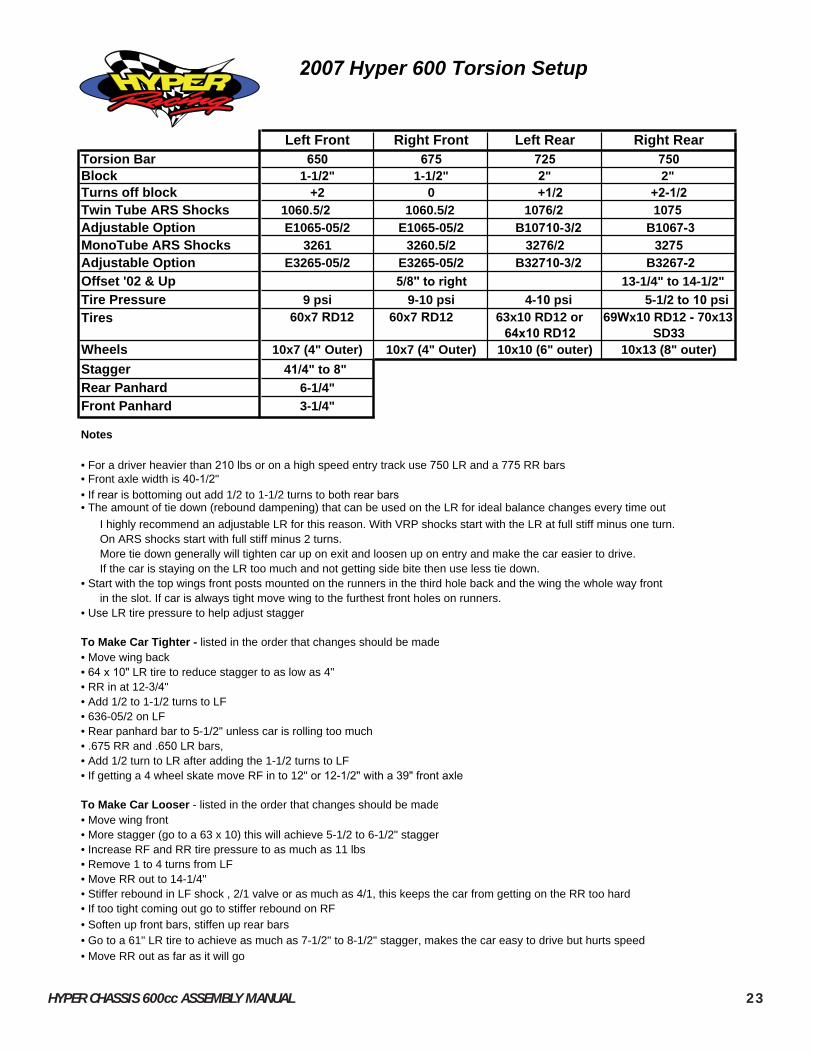
HYPER CHASSIS 600cc ASSEMBLY MANUAL 23
Left Front Right Front Left Rear Right RearTorsion Bar 650 675 725 750Block 1-1/2" 1-1/2" 2" 2"Turns off block +2 0 +1/2 +2-1/2Twin Tube ARS Shocks 1060.5/2 1060.5/2 1076/2 1075Adjustable Option E1065-05/2 E1065-05/2 B10710-3/2 B1067-3MonoTube ARS Shocks 3261 3260.5/2 3276/2 3275Adjustable Option E3265-05/2 E3265-05/2 B32710-3/2 B3267-2Offset '02 & Up 5/8" to right 13-1/4" to 14-1/2"Tire Pressure 9 psi 9-10 psi 4-10 psi 5-1/2 to 10 psiTires 60x7 RD12 60x7 RD12 63x10 RD12 or
64x10 RD1269Wx10 RD12 - 70x13
SD33Wheels 10x7 (4" Outer) 10x7 (4" Outer) 10x10 (6" outer) 10x13 (8" outer)Stagger 41/4" to 8"Rear Panhard 6-1/4"Front Panhard 3-1/4"
Notes
• For a driver heavier than 210 lbs or on a high speed entry track use 750 LR and a 775 RR bars• Front axle width is 40-1/2"• If rear is bottoming out add 1/2 to 1-1/2 turns to both rear bars• The amount of tie down (rebound dampening) that can be used on the LR for ideal balance changes every time out I highly recommend an adjustable LR for this reason. With VRP shocks start with the LR at full stiff minus one turn. On ARS shocks start with full stiff minus 2 turns. More tie down generally will tighten car up on exit and loosen up on entry and make the car easier to drive. If the car is staying on the LR too much and not getting side bite then use less tie down.• Start with the top wings front posts mounted on the runners in the third hole back and the wing the whole way front in the slot. If car is always tight move wing to the furthest front holes on runners.• Use LR tire pressure to help adjust stagger
To Make Car Tighter - listed in the order that changes should be made• Move wing back• 64 x 10" LR tire to reduce stagger to as low as 4"• RR in at 12-3/4"• Add 1/2 to 1-1/2 turns to LF• 636-05/2 on LF• Rear panhard bar to 5-1/2" unless car is rolling too much• .675 RR and .650 LR bars, • Add 1/2 turn to LR after adding the 1-1/2 turns to LF• If getting a 4 wheel skate move RF in to 12" or 12-1/2" with a 39" front axle
To Make Car Looser - listed in the order that changes should be made• Move wing front • More stagger (go to a 63 x 10) this will achieve 5-1/2 to 6-1/2" stagger• Increase RF and RR tire pressure to as much as 11 lbs• Remove 1 to 4 turns from LF• Move RR out to 14-1/4"• Stiffer rebound in LF shock , 2/1 valve or as much as 4/1, this keeps the car from getting on the RR too hard• If too tight coming out go to stiffer rebound on RF• Soften up front bars, stiffen up rear bars• Go to a 61" LR tire to achieve as much as 7-1/2" to 8-1/2" stagger, makes the car easy to drive but hurts speed• Move RR out as far as it will go
2007 Hyper 600 Torsion Setup

HYPER CHASSIS 600cc ASSEMBLY GUIDE 24
Kawasaki ZX6R 600cc '05 - '07 YZF 600R6 '06
R.F. (2)11/16 Spacers w/ 7/16 Hole R.F. (1)11/16 Spacers w/ 1/2 Hole(1) 13/16 Spacer w/ 1/2" Hole (1) 13/16 Spacer w/ 1/2" Hole(2) 7/16-20 x 2 HHCS (2) 1/2 (7/16) Hard Washer(2) 1/2 (7/16) Hard Washer (2) 7/16 AN Washers(2) 7/16 AN Washers (1) 1/2-20 x 2 HHCS(1) 1/2-20 x 2-1/2 HHCS (2) 7/16-20 x 1-1/4 HHCS Must tap engine to 1/2-20 Must tap engine to 1/2-20
L.R.T. 1-1/4 x 7/8 OD w/ 3/8 Hole R.R.T. 3/8 x 7/8 OD w/ 3/8 Hole L.R.T. 1/2 x 7/8 OD w/ 3/8 Hole R.R.T. 0L.R.B. 1/2 x 7/8 OD w/ 3/8 Hole R.R.B. 1/2 x 7/8 OD w/ 3/8 Hole L.R.B. 1/2 x 7/8 OD w/ 3/8 Hole R.R.B. 0
(3) 3/8-16 x 8 HHCS (3) 3/8-16 x 8 HHCS(2) 7/16-20 x 8 HHCS (2) 7/16-20 x 8 HHCS(2) 7/16-20 Nylock Nuts (2) 7/16-20 Nylock Nuts(3) 3/8-16 Nylock Nuts (3) 3/8-16 Nylock Nuts(4) 7/16 (3/8) Hard Washers (4) 7/16 (3/8) Hard Washers(6) 3/8 AN Washers (6) 3/8 AN Washers
Kawasaki ZX6R 636cc '03 & '04 YZF 600R6 '03-'05
R.F. (2)11/16 Spacers w/ 7/16 Hole R.F. (1) 13/16 Spacers w/ 1/2 Hole(1) 13/16 Spacer w/ 1/2" Hole (2) 7/16-20 x 1-1/4 HHCS(2) 7/16-20 x 2 HHCS (2) 7/16 AN Washer(2) 1/2 (7/16) Hard Washer (1) 1/2-20 x 2-1/2 H.H.C.S. (2) 7/16 AN Washers (2) 1/2" Washers(1) 1/2-20 x 2-1/2 HHCS Must tap engine to 1/2-20 Must tap engine to 1/2-20
L.R.T. 1-1/4 x 7/8 OD w/ 3/8 Hole R.R.T. 11/32 x 7/8 OD w/ 3/8 Hole L.R.T. 1/4 x 7/8 OD w/ 3/8 Hole R.R.T. 3/16 x 7/8 OD w/ 3/8 HoleL.R.B. 1/2 x 7/8 OD w/ 3/8 Hole R.R.B. 1/2 x 7/8 OD w/ 3/8 Hole L.R.B. 7/16 x 7/8 OD w/ 3/8 Hole R.R.B. 0
(3) 3/8-16 x 8 HHCS (2) 3/8-16 x 8 HHCS Must modify oil pan on front left. (2) 7/16-20 x 8 HHCS (2) 7/16-20 x 8 HHCS On 2003 and older cars(2) 7/16-20 Nylock Nuts (2) 7/16-20 Nylock Nuts(3) 3/8-16 Nylock Nuts (2) 3/8-16 Nylock Nuts(4) 7/16 (3/8) Hard Washers (4) 7/16 (3/8) Hard Washers(6) 3/8 AN Washers (4) 3/8 AN Washers
GSXR 600 '06 Honda RR '03-'06 R.F. (2) 5/8 Spacers w/ 7/16 Hole(1) 11/16 Spacer w/ 1/2" Hole
R.F. (1) 7/16 Spacers w/ 1/2 Hole (2) 7/16-20 x 2 HHCS(2) 7/16-20 x 1-1/4 HHCS (2) 1/2 (7/16) Hard Washer(2) 7/16 AN Washer (2) 7/16 AN Washers(1) 1/2-20 x 2 H.H.C.S. (1) 1/2-20 x 3-1/4 HHCS(2) 1/2" Washers (1) 1/2-20 Full Nut Must tap engine to 7/16-20 Must tap engine to 1/2-20
L.R.T. 0 R.R.T. 1-3/32 x 7/8 OD w/ 3/8 Hole L.R.T. 1/8 x 7/8 OD w/ 3/8 Hole R.R.T. 7/8 x 7/8 OD w/ 3/8 HoleL.R.B. 3/8 x 7/8 OD w/ 3/8 Hole R.R.B. 1-3/32 x 7/8 OD w/ 3/8 Hole L.R.B. 5/8 x 7/8 OD w/ 3/8 Hole R.R.B. 15/16 x 7/8 OD w/ 3/8 Hole
(2) 3/8-16 x 8 HHCS (3) 3/8-16 x 8 HHCS(2) 7/16-20 x 8 HHCS (2) 7/16-20 x 8 HHCS(2) 7/16-20 Nylock Nuts (2) 7/16-20 Nylock Nuts(2) 3/8-16 Nylock Nuts (3) 3/8-16 Nylock Nuts(4) 7/16 (3/8) Hard Washers (4) 7/16 (3/8) Hard Washers(4) 3/8 AN Washers (6) 3/8 AN Washers
ENGINE MOUNT SPACER & BOLT LIST

HYPER CHASSIS 600cc ASSEMBLY MANUAL 25
GSXR Suzuki 600cc '01-'04 YZF 600R6 1999-2002
R.F. (1)11/16 Spacers w/ 7/16 Hole R.F. (1) 1-1/16 Spacers w/ 1/2 Hole(2) 7/16-20 x 1-1/4 HHCS (2) 7/16-20 x 1-1/4 HHCS(2) 7/16 AN Washer (2) 7/16 AN Washer(2) 7/16 (3/8) AN Hard Washers (1) 1/2-20 x 2-1/2 H.H.C.S.(1) 7/16-20 x 1-3/4 HHCS (2) 1/2" Washers Must tap engine to 7/16-20 Must tap engine to 7/16-20
L.R.T. 11/16 x 7/8 OD w/ 3/8 Hole R.R.T. 7/16 x 7/8 OD w/ 3/8 Hole L.R.T. 1/8 x 7/8 OD w/ 3/8 Hole R.R.T. 1/4 x 7/8 OD w/ 3/8 HoleL.R.B. 0 R.R.B. 1 x 7/8 OD w/ 3/8 Hole L.R.B. 3/8 x 7/8 OD w/ 3/8 Hole R.R.B. 0
(2) 3/8-16 x 8 HHCS (2) 3/8-16 x 8 HHCS Must modify oil pan on front left (2) 7/16-20 x 8 HHCS (2) 7/16-20 x 8 HHCS on 2003 and older cars(2) 7/16-20 Nylock Nuts (2) 7/16-20 Nylock Nuts(2) 3/8-16 Nylock Nuts (2) 3/8-16 Nylock Nuts(4) 7/16 (3/8) Hard Washers (4) 7/16 (3/8) Hard Washers(4) 3/8 AN Washers (4) 3/8 AN Washers
GSXR Suzuki 1000cc ''05 CBR 600cc F3
R.F. (1) 11/16 Spacers w/ 1/2 Hole R.F. (2) 11/16 Spacers w/ 7/16 Hole(1) 1/2-20 x 2 HHCS (2) 7/16-20 x 2 HHCS(2) 1/2 (7/168) AN Hard Washers (1) 7/16-20 Nylock Nut(2) 7/16-20 x 1-1/4 HHCS (3) 7/16 AN Washer(2) 7/16 AN Washer (2) 7/16 (3/8) AN Hard Washers Must tap engine to 1/2-20 (1) 7/16-20 x 2-1/4 HHCS
Must tap engine to 7/16-20
L.R.T. 0 R.R.T. 1/2 x 7/8 OD w/ 3/8 Hole L.R.T. 0 R.R.T. 5/16 x 7/8 OD w/ 3/8 HoleL.R.B. 41/64 x 7/8 OD w/ 3/8 Hole R.R.B. 1-1/8 x 7/8 OD w/ 3/8 Hole L.R.B. 1/2 x 7/8 OD w/ 3/8 Hole R.R.B. 3/8 Regular Washer
(3) 3/8-16 x 8 HHCS (2) 3/8-16 x 8 HHCS(2) 7/16-20 x 8 HHCS (2) 7/16-20 x 8 HHCS(2) 7/16-20 Nylock Nuts (2) 7/16-20 Nylock Nuts(3) 3/8-16 Nylock Nuts (2) 3/8-16 Nylock Nuts(4) 7/16 (3/8) Hard Washers (4) 7/16 (3/8) Hard Washers(6) 3/8 AN Washers (4) 3/8 AN Washers
ENGINE MOUNT SPACER & BOLT LIST

HYPER CHASSIS 600cc ASSEMBLY GUIDE 26
Where Used Description Type Quantity
Bag 01 Rear EndShock to frame Shock Pins Not included in bolt kit Shackle to torsion arm (use rod end spacer) 7/16-20 x 2 H.H.C.S. 2
7/16-20 Nyloc Half Nut 2 Wish Bone to Frame 1/2-20 x 1-1/2 H.H.C.S. 2 Radius rod to bird cage (use rod end spacer) 7/16-14 x 1-3/4 H.H.C.S. 4 Panhard to Birdcage 7/16-14 x 1-1/8 H.H.C.S. 1 Brake caliper to bird cage 3/8-24 x 1 H.H.C.S. 2
3/8-24 Nyloc Half Nut 2 3/8 An Washer 2
Shackle to Bridcage (Torsoin Only) 7/16-20 x 2-1/4” H.H.C.S. 2 7/16-20 Nyloc Half Nut 2
Bag 03For 8” or 9-1/4” Rotor 5/16-18 x ¾ H.H.C.S. 4
5/16 AN Washer 4 Bag 05 Front EndPanhard to Axle 7/16-20 Nyloc Full Nut 1 Shock to frame Use Shock Pins Not included in bolt kit
Shock to front axle 3/8-24 x 1-1/2 H.H.C.S. 2 3/8 AN Washer 2
Radius rod to front axle Left Side 7/16-20 x 1-3/4 H.H.C.S. 1 Radius rod to front axle Right Side 7/16-20 x 1-1/4 H.H.C.S. 2
7/16-20 Nyloc Half Nut 3 Radius rod to frame 7/16-20 x 1-1/4 H.H.C.S. 3 Bag 06 SteeringSteering rods to steering arms 7/16-20 x 1-1/2 H.H.C.S. 2
7/16-20 Nyloc Nut 2 Steering Arms to Spindle 3/8-24 x 1-¼ H.H.C.S. 4
3/8 AN Washer 4 Steering arms to steering box 7/16-20 x 1-1/2 H.H.C.S. 2
7/16-20 Nyloc Nut 2 Rack box to axle clamp 3/8-16 x 2-1/4 H.H.C.S. 2
3/8 AN Washer 2 Bag 08 Steering Wheel Steering wheel to hub 5/16-18 x 3/4 H.H.C.S. 3
5/16 AN Washer 3 Bag 09 Universal JointUniversal joint ¼-28 x ½ HHCS 8
¼-28 Jam Nut (no nyloc) 8Bag 12 BumpersBumpers and nerf bars 10-24 x 1-1/2 S.H.C.S. 14
10-24 Nyloc Nut 14 Wing Sockets 10-24 x 1-1/4 S.H.C.S. 2
10-24 Nyloc Half Nut 2
2007 600cc Hyper Rolling Chassis Bolt List

HYPER CHASSIS 600cc ASSEMBLY MANUAL 27
Bag 19 Belly PanBelly Pan and Battery Box to Frame 1/4-20 x 1/2 B.H.C.S. 9
1/4-20 Nyloc Half Nut 9 1/4 A.N. Washer 9 Plastic Push Pins 2
Bag 22 Bell Crank Panhard AdjusterPanhard Bar to Slider Bracket 7/16-20 x 1-1/4 H.H.C.S. 1
7/16-20 Nyloc Half Nut 1Slider Bar to Frame 5/16-24x 1-3/4 H.H.C.S. 2
5/16-24 Nyloc Half Nut 2Rod to Slider Bracket 1/4-28 Nyloc Nut 1Handle to Frame 5/16-24 x ¾ H.H.C.S. 2
5/16 A.N. Washers 2Rod to Handle 1/4-28 x 1-1/2 H.H.C.S. 1
¼-28 Nyloc Half Nut 1¼ AN Washer 1
½ od x 5/8 lg Spacer 1Rods to Bell Crank ¼-28 x 3/4 H.H.C.S. 2
¼-28 Nyloc half Nut 2Bell Crank to Frame ¼-28 x 2 H.H.C.S. 1
¼-28 Nyloc half Nut 1Bag 23 Nose Wing Assembly Posts to Wing 10-32 x 7/8 S.H.C.S. 2
#10 AN Washers 210-32 Nyloc Half Nuts 2
Straps to Wing 10-24 x ¾ S.H.C.S. 2#10 AN Washers 410-24 Nyloc Half Nuts 2
Posts to Frame 10-24 x 7/8 S.H.C.S. 210-24 Nyloc Half Nuts 2
Bag 24 Front Mount Radiator Bracket to Frame 3/8-24 x ¾ H.H.C.S. 2
3/8 AN Washers 2 3/8-24 Nyloc Half Nut 2
Bag 16 SeatSeat to frame 3/8-24 x 1 B.H.C.S. 4
3/8 Fender washer 4 Seat Bars to Frame 3/8-24 x 1 F.H.C.S. 4
3/8-24 Half Nut 8 3/8-24 x 1-3/4 H.H.C.S. 4 3/8 AN Washer 4
Bag 15 Direct ShifterRod to Shifter Link ¼-28 x 3/4 H.H.C.S. 1 Rod to Engine ¼-28 x 1 H.H.C.S. 1
¼-28 Nyloc Nut 2
Bolt list continued on next page

HYPER CHASSIS 600cc ASSEMBLY GUIDE 28
Bag 50 Wing Clamp Rear Upright Pinch Clamps 5/16-18 x1-1/2 H.H.C.S. 2
5/16-18 Half Nut Plain 25/16 AN Washers 4
1Bag 02 Included with clamp Panhard Bar to pinch clamp 7/16-20 x 2 H.H.C.S. 1
7/16-20 Nyloc Nut 17 /16 AN Washer 1
Panhard pinch clamp 1/4-28 x 2 H.H.C.S. 11/4-28 Nyloc Nut 11/4 AN Washer 1
1 Dark Grey indicates not included in new chassis bolt kit
Bag 04 Torsion Arm & Jacker Torsion Arm and Stop Pinch Bolt 5/16-24 x 2 H.H.C.S. 8
5/16-24 Nyloc Nut 85/16 AN Washer 16
Torsion Jacker Bolt 5/16-18 x 1-1/2 S.H.C.S. 45/16-18 Thin Nut 4
dark grey shading indicates bolts not included with the new chassis bolt kit

HYPER CHASSIS 600cc ASSEMBLY MANUAL 29
NOTES

HYPER CHASSIS 600cc ASSEMBLY GUIDE 30
NOTES