assembly instructions operator's manual parts …shortlineag.com/hd10 manual.pdf ·...
TRANSCRIPT
SAKUNDIAK ---
ASSEMBLY INSTRUCTIONS OPERATOR'S MANUAL
PARTS LIST
HD1 0 BELT DRIVE AUGER MODEL NO.
HD10-1400BD HD10-1600BD HD10-1800BD HD1 0-200080
SAKUNDIAK EQUIPMENT L TO. 2800 PASQUA ST. NORTH
REGINA, SK CANADA PO BOX 1996- S4P 3E1
PHONE : (306) 545-4044 FAX : (306) 545-4216 www.sakundiak.com e-mail : [email protected]
PRINTED IN CANADA HD1 080.00.00

cc.;:::::;. ----------------- SAKUNDIAK -----------------.... ~
TABLE OF CONTENTS SECTION .00 "GENERAL"
+ COVER SHEET + TABLE OF CONTENTS + SIGN OFF SHEET + GENERAL SAFETY
SECTION .01 "SAFETY"
+MACHINE INSPECTION +DESIGNATED WORK AREA + SAFETY GUARD DESCRIPTION + TRANSPORT AND PLACEMENT + AUGER DRIVES AND LOCK OUT + AUGER DRIVES AND LOCK OUT
SECTION .02 "OPERATIONS"
+ START UP AND BREAK-IN +LUBRICATION AND MAINTENANCE +SAFETY DECALS AND LOCATIONS +SAFETY DECALS AND LOCATIONS
SECTION .03 "ASSEMBLY"
+ MAIN FRAME AND A-FRAME ASSEMBLY +TUBE ASSEMBLY + BELT DRIVE PTO CONVERSION
SECTION .04 "PARTS"
+ HEAD - END ASSEMBLY + GEAR BOX ASSEMBLY + MAIN FRAME ASSEMBLY (PICTURED) + MAIN FRAME ASSEMBLY (PARTS LIST) + A-FRAME ASSEMBLY + MOTOR MOUNT ASSEMBLY + TUBE ASSEMBLY (PICTURED) + TUBE ASSEMBLY (PARTS LIST) + TUBE ASSEMBLY (PARTS LIST) Continued + P.T.O. ATIACHMENT + P.T.O. SHAFT + BRAKE WINCH ASSEMBLY
SECTION .05 "INDEX"
+ PARTS INDEX PAGE
SECTION .06 "WARRANTY"
+ WARRANTY AND DISCLAIMER
HD1080.01.00
0 1 2 3
4 5 6 7 8 9
10 11 12 13
14 15 16
17 18 19 20 21 22 23 24 25 26 27 28
29
30

SAKUNDIAK
'<:::S27 " SAKUNDIAK GRAIN AUGER SIGN OFF SHEET
As a requirement of OSHA, it is necessary for the employer to train the employee in the safe operation and safety procedures with this auger. We include this sign-up sheet for your convenience and personal record keeping.
DATE EMPLOYER SIGNATURE EMPLOYEE SIGNATURE
2 __, HD10BD.02.00

~ ,.---------------- SAKUNDIAK ----------------'27
GENERAL SAFETY
Watch This Symbol. It Points Out Important Precautions. It Means "ATTENTION- Become Alert!
Your Safety is Involved"
Occupational safety is of prime concern to Sakundiak Equipment Ltd. This transport manual was written with the safety of the operator and others who come in contact with the equipment as our prime concern. The manual presents some of the day to day work problems encountered by the operator and other personnel. We wrote this manual to help you understand safe operating procedures for augers. We want you as a partner in the safe operation of our equipment.
It is your responsibility as an owner, or operator or supervisor, to know what specific requirements, precautions and work hazards exist and to make these known to all other personnel working with the equipment or in the area, so that they too may take any necessary safety precautions that may be required.
Failure to read this Transport Auger Manual and its Safety Instructions is a misuse of the equipment.
3-----------------------------------------------------------' HD10BD.OJ.OO
cc::;:::;;. ~--------------------------------------&AKUNDIAK--------------------------------------~ <:::::s27
SECTION .01 SAFETY ALERT SYMBOLS
BE ALERT This symbol is used to call your attention to instructions concerning your personal safety.
Watch for this symbol- it points out important safety precautions. It means "ATTENTION! Become Alert! Your Personal Safety is Involved!" Read the message that follows and be alert to the possibility of personal injury or death.
MACHINE INSPECTION
1. Check to see that all guards listed in the assembly instructions are in place and secured, and functional.
2. Check winch and cable for security and operation . There should be at least 3 complete wraps of cable around winch drum in full down position. Cable anchor on winch drum must be tight.
3. Are all fasteners tight?
4. Are all chains properly adjusted. (See Maintenance Section)
5. Check oil levels in gear box. (See Maintenance Section)
OPERATOR QUALIFICATIONS
Operator of this transport auger shall be limited to competent and experienced persons. In addition, anyone who will operate or work around a portable auger must use common sense. In order to be qualified, they must know and meet all other requirements, such as:
1. Some regulations specify that no one under the age of 16 may operate power machinery. This includes augers and flight type elevators. It is your responsibility to know what these regulations are in your area or situation.
2. Current OSHA regulations state in part: "At the time of initial assignment and at least annually thereafter, the employer will instruct every employee in the safe operation and servicing of all equipment with which the employee is, or will be involved."
3. Unqualified persons are to stay out of the work areas.
4. A person who has not read and understood all the operating and safety instructions is not qualified to operate the machine.
~----------------------------------------------------------4 HD10BD.04.00

cz::;;;:::;. ~------------------ SAKUNDIAK ------------------...... <::::S27
DESIGNATED WORK AREA
The following diagrams will show the designated work areas. These areas shall be marked off with colored nylon or plastic rope hung by portable barriers to define the designated work areas.
Under no circumstances should persons not involved in the operation be allowed to trespass into the work area.
It shall be the duty of all operators to see that children and/or other persons stay out of the work area! Trespass into the area by anyone not involved in the actual operation, or trespass into a hazard area by anyone, shall result in an immediate shut down by the operator.
Prior to start up and during operation, it shall be the responsibility of the operators to see that the work area has secure footing, is clean and free from all debris, and tools which might cause accidental tripping and/or falling .
P.T.O. BELT DRIVE
CAUTION! _A, WALKING SURFACE, .. IS IT SLIPPERY?
ARE THERE THINGS TO TRIP YOU?
A HAZARD, KEEP OUT, AUGER INTAKE AREA.
A KEEP AWAY!
OVERHEAD WIRES~
HAZARD, KEEP OUT! A UNDER AUGER AND UNDERCARRIAGE AREA_
WHEEL CHOCKS. I --------- " " \ 1
I I I I I I L _________ _
A HAZARD, KEEP OUT, AUGER DRIVE AREA. P.T.O. DRIVE AREA.
WORK AREA AUTHORIZED PERSONNEL ONLY.
WHEEL CHOCKS.'----+_/
./
SUPPORT DISCHARGE END.
\ I I I
I I
/
5---------------------------------------------------------------' HD1080.05.00

cz:;::;:,. ~-----------------~K------------------~
SAFETY GUARD DESCRIPTION
HEAD-END
GEAR BOX SHAFT GUARD
TUBULAR DRIVE SHAFT GUARD
INTAKE FORK
ENGINE PULLEY GUARD
GEAR BOX PULLEY GUARD
P.T.O. ATTACHMENT GUARD
~----------------------------------------6 HD10BD.06.00

~ ~----------------- &AKUNDIAK -----------------.... <::::::s27
TRANSPORTANDPLACEMENT Moving the Auger with the Towing Vehicle to or from the Work Area.
1. Always transport your auger in the full down position. The A-Frame of the undercarriage should be seated against the down position stop.
2. Make sure that the hitch pin is securely attached and an alternate safety chain is secure to the auger and towing vehicle.
3. Be alert of overhead obstructions and electrical wires. Electrocution can occur with out direct contact. Failure to do so will result in severe injury or death.
4. Never allow persons to stand underneath or ride on the auger when it is being transported.
A KEEP AWAY! .. OVERHEAD WIRES
II
Placement: Moving the Auger with the Towing Vehicle into or out of its Working Position.
Always move an auger with a vehicle, never manually. Test the intake for downward weight before removing from hitch. Lift slowly, no higher then hitch bar. Be sure grain is out of tube and auger is on level surface. Do not place lumber under wheels for increased weight. Before raising, check for power lines. When auger is in place, anchor intake end and/or discharge end and chock wheels. When in transport or placement PTO shaft to be disconnected.
OVERHEAD WIRES KEEP AWAY!
7 ----------------------------------------------------------------------------' HD10BD.07.00
~ ~--------------------------------------SAKUNDIAK--------------------------------------~ ~
AUGER DRIVES AND LOCK OUT It is essential to inspect your drive before
adding power and know how to shut down in an emergency.
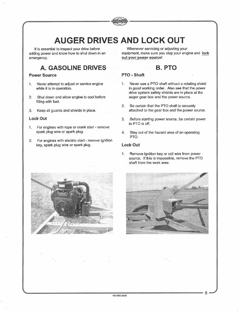
A. GASOLINE DRIVES Power Source
1. Never attempt to adjust or service engine while it is in operation.
2. Shut down and allow engine to cool before filling with fuel.
3. Keep all guards and shields in place.
Lock Out
1. For engines with rope or crank start - remove spark plug wire or spark plug .
2. For engines with electric start- remove ignition key, spark plug wire or spark plug.
Whenever servicing or adjusting your equipment, make sure you stop your engine and lock out your power source!
B.PTO PTO- Shaft
1. Never use a PTO shaft without a rotating shield in good working order. Also see that the power drive system safety shields are in place at the auger gear box and the power source.
2. Be certain that the PTO shaft is securely attached to the gear box and the power source.
3. Before starting power source, be certain power to PTO is off.
4. Stay out of the hazard area of an operating PTO.
Lock Out
1. Remove ignition key or coil wire from power source. If this is impossible, remove the PTO shaft from the work area.
HD10BD.08.00

cz.>:::::,.. ~--------------------------------------&AKUNDIAK--------------------------------------~ ~
AUGER DRIVES AND LOCK OUT C. ELECTRIC
Power Source
1. Electric motors and controls shall be installed by a qualified electrician and must meet the standards set by the National Standards Electrical Code.
2. A magnetic starter should be used to protect your motor.
3. You must have a manual reset button.
4. You must disconnect power before resetting your motor.
5. Reset and motor controls must be located so the operator has full view of the entire operation.
6. Keep all guards and shields in place.
Lock Out
A main power disconnect switch capable of being locked only in the Off position shall be provided. This shall be locked whenever work is being done on the auger.

~ ~--------------------------------------SAKUNDIAK--------------------------------------~ ~
SECTION .02- OPERATIONS
START-UP AND BREAK-IN Sakundiak Equipment Ltd. recommends that
before you start augering grain with your new auger that you should do the following:
1. Run the grain auger at approximately 1/2 the normal operating speed (270 rpms with PTO) without adding grain to the intake for approximately five minutes.
2. Bring auger up to full operation speed (540 rpms with PTO) and slowly add grain to intake of auger.
3. Continue to add grain slowly until approximately 1000 bushels (28 tonnes) has been run through the grain auger. This will "shine up" the flighting and the tube.
4. The operator should be aware if any unusual vibrations or noises, determine source, shut off, LOCK OUT power source and adjust.
OLD AUGER START-UP AND BREAK-IN
Sakundiak Equipment Ltd. recommends that before augering grain with your used auger, you should do the following:
1. Before positioning the auger, be sure all guards and shields are in place, securely fastened and fully operational.
2. Check and fill if necessary, all lubricating fluids, and grease all fittings.
CAUTION 1. Observe work area restrictions (see work area
diagram.)
2. Keep all safety guards and shields in place.
3. Make certain everyone is clear before operating or moving the machine.
4. Keep hands, feet, and clothing away from all moving parts.
5. Lock out power sources to adjust, service or clean.
EMERGENCY SHUT -DOWN 1. Should the auger be immediately shut down
under load --- disconnect and lock out the power source. Clear as much grain from the hopper and auger as you can. Never attempt to start the auger full.
2. Starting the auger under load may result in damage to the auger. Such damage is considered abuse of the equipment.
3. Reconnect power source and clear grain gradually.
NORMAL SHUT-DOWN 1. Make sure that the hopper and auger are empty
before stopping the unit.
2. Before the operator leaves the work area, the power source shall be locked out.
CLEAN-UP AND STORAGE When the operation is completed, it is
recommended that you move the auger to the new work area or to a storage area .
1. Clean entire work area.
2. Remove anchors, supports and chocks .
3. Move auger slowly out of working position with towing vehicle --- not by hand. (see transport and placement)
4. When augering out of bin is complete, do not attempt to pull on axle with tractor to remove from bin. This will bend the auger.
5. If not in transport position , lower auger to the full down position immediately upon clearance of any obstruction .
6. Transport to new work area or storage area. We recommend that the auger be stored in the full down position with intake end anchored.
7. Do not attempt to pull grain auger out of snow bank in winter. This will cause damage to the tube assembly.
8. Make certain that there is no snow build up on auger tube or frame, which will bend the auger frame or auger tube
'---------------------------------------------------------------------------------------10 HD108D.1 0.00

~ ~------------------------------------SAKUNDIAK------------------------------------~ ~
AUGER LUBRICATION AND MAINTENANCE DANGER Do not service or lubricate while the auger is running. LOCK OUT the power source.
GEAR BOX
1. 10 inch grain augers, fill with 2 quarts (2 litres) of #90 gear oil.
2. Do not over fill gear box.
3. Change oil once a year or every 20,000 bushels (550 tonnes) or when it gets contaminated with water.
DRIVE SHAFT BEARINGS
1. Grease once a day with good quality grease.
HEAD-END
1. The bearings are pre-lubricated and do not require further lubrication.
2. The sprockets and chain should be oiled with #130 gear oil once every season.
3. Keep chains snug , do not over tighten.
FORK BEARING
1. Grease every 1,000 or 2,000 bushels (28 or 54 tonnes) with a good quality grease.
WHEEL BEARINGS
1. The wheel bearings are packed at the factory.
2. They should be cleaned and repacked once a year.
PTO SHAFT AND ATTACHMENT
1. PTO shaft and attachment should be greased once a day with a good quality grease.
11-----------------------------------------------------------' HD10BD.11.00

~ ~_. ..................................................... SAKUNDIAK ...................................................... ._~
;;;::::s::?
~CAUTION 1. Do not operate this auger before reading and
understanding the operator's manual.
2. Do not operate this auger unless all guards and safety devices are securely in place.
3. Do not adjust, service, lubricate, clean, unclog or move this unit until all power has been shut off.
4. Make certain everyone is clear of the equipment before moving or operating. Never allow children, v1s1tors or untrained personnel in the area.
5. Keep hands, feet and clothing clear of all moving parts while in operation.
6. Support discharge end or anchor intake end to prevent upending.
7. Empty auger and lower to transport position before moving to prevent upending.
8. Lower this unit to transport position when not in use.
9. When raising or lowering auger watch for overhead powerlines and other obstructions.
1 0. Disengage belt tension release on motor base before starting motor.
11 . Disconnect power on electric motor driven units before resetting motor overload make certain electric motors are properly gro~nded .
12. Always make certain that trained personnel are in attendance while unit is in operation.
A DANGER
Upending Hazard The intake end of the grain auger must always have downward weight.
Always test it before releasing it from the vehicle or holddown.
Lift the intake slowly and keep it no higher than the tractor tow bar when attaching or releasing it.
Immediately lower the auger to transport position before moving.
Failure t? do so will cause upending, Which Will result in serious injury or death. 1655
A DANGER
ROTATING FLIGHTING Keep away from intake end. Failure to do so will result in serious injury or death.
Do not use this auger without intake guard in place.
1651
1653
To Prevent Serious Injury or Death · Avoid unsafe operation or
maintenance.
· Do not operate or work on this machine without reading and understanding the operator's manual.
· If manual is lost, contact your nearest dealer for a new manual.
A DANGER ELECTROCUTION HAZARD
To prevent serious injury or death from electrocution:
• Stay away from overhead powerlines when transporting or raising augers. This machine is not grounded. Electrocution can occur without direct contact.
1656
~----------------------------------------------~H:D~10~8~0~.1~2.~00~----------------------------------------• 12
Cf3:::> ~_._._. ................................................. SAKUNDIAK --------------------------------------------------------...
~
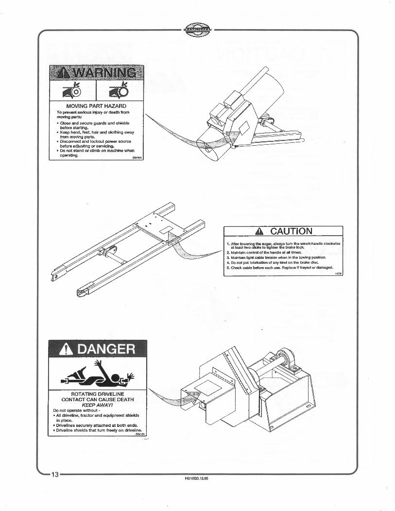
MOVING PART HAZARD To prevent serious injury or death from moving parts:
• Close and secure guards and shields before starting.
• Keep hand, feet, hair and clothing away from moving parts.
• Disconnect and lockout power source before adjusting or servicing.
• Do not stand or climb on machine when operating.
A DANGER
ROTATING DRIVELINE CONTACT CAN CAUSE DEATH
KEEPAWAY! Do not operate without -• All driveline, tractor and equipment shields
in place. • Drivelines securely attached at both ends. • Driveline shields that tum freely on driveline.
SW101
A CAUTION 1. After lowering the auger, always tum the winch handle clockwise
at least two clicks to tighten the brake lock.
2. Maintain control of the handle at all times.
3. Maintain light cable tension when in the towing position.
4. Do not put lubricatJon of any kind on the brake disc.
5. Check cable before each use. Replace if frayed or damaged.
1659
13------------------------------------------------------------------------------------------' HD1080.13.00

~------------------------------------s~K------------------------------------~ '27
SECTION .03 -ASSEMBLY
NOTE: Reference to right and left hand used throughout this manual refers to the position standing at the intake end looking toward the head-end.
MAIN FRAME ASSEMBLY 1. Lay frame out as shown in figure (No.01)
2. Fasten Main Frame to axle using 7/16" dia. bolts. (do not tighten)
3. Install Main Frame to axle braces and main frame cross brace at the same time.
4. Install winch base plate and belt idler bracket.
5. Bolt on winch.
6. Fasten battery mount.
7. Assemble cable roller bracket and mount frame.
8. Leave out two bolts on winch plate so Main Frame can be spread apart to fit on tube pins.
1.
2.
A-FRAME ASSEMBLY Lay out frame as shown in figure (No.01)
Install spindles in frame using the last or bottom holes in the A-Frame.
3. Place A-Frame so the stub on the Main Frame axle can be slid into the second hole on the A-Frame. Now do the same on the other side. Both pieces should be installed on the axle and be pointing in the opposite direction. (Fig. No.01)
4. Install A-Frame cross brace on A-Frame.
5. Mount gooseneck to the A-Frame, using the middle holes on the gooseneck and the upper end of AFrame.
6. Install track roller brackets and track roller as shown in figure (No.02). (Do not tighten)
7. When assembling swing augers, install lift cable roller at the upper end of gooseneck.
8. Mount tires on rims and mount rims on axle spindles.
FIGURE 02
FIGURE 01
~--------------------------------------------~~~----------------------------------------14 HD10BD.14.00
cc;;:::;:., ~------------------------------------&AKUNDIAK------------------------------------~ ~
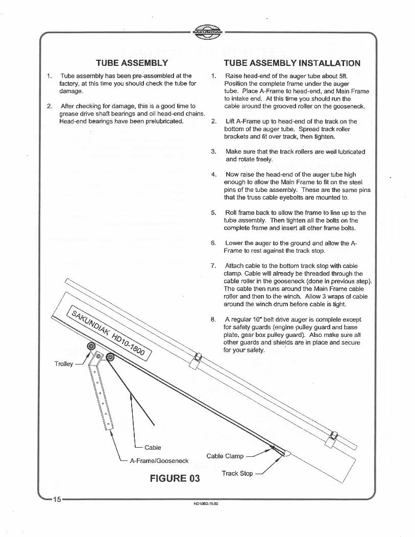
TUBE ASSEMBLY TUBE ASSEMBLY INSTALLATION 1. Tube assembly has been pre-assembled at the 1.
factory, at this time you should check the tube for damage.
Raise head-end of the auger tube about 5ft. Position the complete frame under the auger tube. Place A-Frame to head-end, and Main Frame to intake end. At this time you should run the
2. After checking for damage, this is a good time to grease drive shaft bearings and oil head-end chains.
cable around the grooved roller on the gooseneck.
Head-end bearings have been prelubricated. 2. Lift A-Frame up to head-end of the track on the bottom of the auger tube. Spread track roller brackets and fit over track, then tighten.
A-Frame/Gooseneck
FIGURE 03
3. Make sure that the track rollers are well lubricated and rotate freely.
4. Now raise the head-end of the auger tube high enough to allow the Main Frame to fit on the steel pins of the tube assembly. These are the same pins that the truss cable eyebolts are mounted to.
5. Roll frame back to allow the frame to line up to the tube assembly. Then tighten all the bolts on the complete frame and insert all other frame bolts.
6. Lower the auger to the ground and allow the AFrame to rest against the track stop.
7. Attach cable to the bottom track stop with cable clamp. Cable will already be threaded through the cable roller in the gooseneck (done in previous step). The cable then runs around the Main Frame cable roller and then to the winch. Allow 3 wraps of cable around the winch drum before cable is tight.
8. A regular 1 0" belt drive auger is complete except for safety guards (engine pulley guard and base plate, gear box pulley guard). Also make sure all other guards and shields are in place and secure for your safety. ·
Cable Clamp
Track Stop
15-------------------------------------------------------------' HD10BD.15.00

~ ~------------------------------------SAKUNDIAK------------------------------------~ ~
BELT DRIVE PTO CONVERSION 1. Mount PTO base onto motor mount base. (leave
bolts loose)
2. Bolt quard mounting brackets to PTO base on the side that has bolt holes. The small ends of the bracket bolts onto the PTO base.
3. Bolt the quard base to the large end of the brackets.
4. Take the V-pulley in the PTO kit and mount it on the gear box of the main auger tube. Hub of the V-pulley must face into gear box.
5. Take the old V-pulley from the gear box and mount it on the PTO shaft of the PTO base. Face the hub of the V-pulley into the PTO base.
6. Bolt guard cover onto guard base.
7. Slide splined coupler onto PTO drive shaft and then tighten the screws.
8. Bolt cover guard to V-pulley guard.
P.T.O. Attachment
Pulley
Guard Mounting Brackets
Guard Back
Guard Cover Spline Guard
FIGURE 04
Hinge
'-------------------------------------------------------------16 HD1080.16.00

~ ~------------------------------------SAKUNDIAK------------------------------------~ ~
REF NO.
1 2 3 4 5 6 7 8 9
10 11 12 13 14 15 16 17
HD10
1747 1551 1619 1623
1625 1743
2341 1964 1953 2362 2363 1620 1585
1 1 1 1 2 1 1 6 8 8 1
HEAD-END ~~
Bearing insert is available in set screw or locking collar. See REF NO. 14-17 below. Also available is the set screw bearing c/w casting. See REF NO. 12 & 13 below.
DESCRIPTION
Head-end base plate 1 1/2" Locking collar bearing c/w casting 1 1/2" Bore 16 tooth sprocket 1 1/2" Bore 28 tooth sprocket 1/4" x 7/8" Woodruff key No. 80-42 c/w connecting link Head-end cover 1/4" x 1/2" Self-tapping screws 5/8" x 1 1/2" UNC Bolts 5/8" Whiz Nut 1 1/2" Locking collar bearing c/w casting 1 1/2" Set screw bearing c/w casting (Optional for REF NO.2) 1 1/2" Set screw bearing c/w casting (Optional for REF NO. 11) 1 1/2" Locking collar bearing insert for REF NO. 2 1 1/2" Locking collar bearing insert for REF NO. 11 1 1/2" Set screw bearing insert for REF NO. 12 1 1/2" Set screw bearing insert for REF NO. 13
17~~---------~~------~~-------------------------------------------------------' H0 10BD.17.00

~------------------------------------6~------------------------------------~ ~
GEARBOX
DESCRIPTION
1 1626 1 Gear box housing 2 1627 1 Double bearing cover 3 1628 2 Single bearing cover 4 1629 2 Bevel gear 5 1630 2 Tapered roller bearing 6 1631 2 Tapered roller bearing 7 1632 4 Tapered bearing cup 8 1633 4 Snap ring 9 12 1/2" UNC bolt 10 12 1/2" Lock washer 11 1634 1 1 3/8" Stakenut 12 1635 1 1 1/2" Stakenut 13 1636 1 Input shaft 14 1637 1 Output shaft 15 2 121 0 Woodruff key 16 1638 2 1 3/8" I.D. Oil seal 17 1639 1 1 3/4" I.D. Oil seal 18 1640 1 3/8" NPT Oil level plug 19 1641 1 3/8" NPT Oil drain plug 20 1083 1 Vent and plug bushing 21 1642 3 Gasket 22 1643 3 Shim 23 3 Square key
1540 Gear box complete
'-----~--------~------~------------------------------------18 HD10BD.18.00
......
(.CJ
J:
c ~
c CJ
m
r ---4
c ;a - < m
Not
e:
s: )> - ~~~
)>~
3:
m
Re
f N
o.'s
13
, an
d 21
thr
u 25
ar
e st
anda
rd f
or 1
600
, 18
00
2000
Ser
ies
HD
10 a
uger
s,
and
are
optio
nal f
or 1
400
Ser
ies
HD
10 a
uger
s.

&AKUNDIAK , ~ """
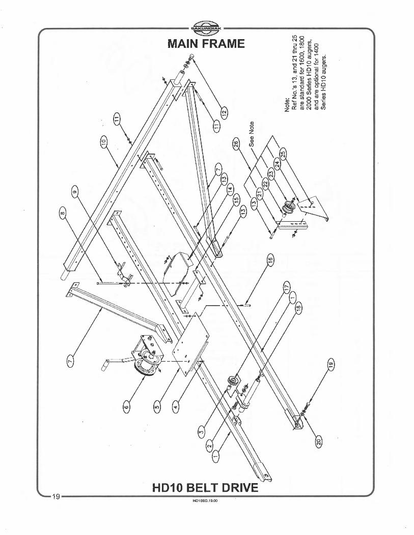
MAIN FRAME HD1 0 BELT DRIVE
REF NO. HD10 NO. USED DESCRIPTION
1 2580 2 Main frame - 1400 1 2581 2 Main frame - 1600 1 2582 2 Main frame - 1800 1 2583 2 Main frame - 2000 2 - 1 5/8" x 2 1/2" UNF bolt c/w nut and lock washer 3 1381 1 Cable roller bushing 4 - 4 3/8" x 1" UNC bolt c/w whiz nut 5 1523 1 Winch base plate 6 1681 1 Brake winch - 2550 7 2403 2 Main frame to axle brace- 1400 7 2404 2 Main frame to axle brace- 1600 7 2405 2 Main frame to axle brace- 1800 7 2406 2 Main frame to axle brace - 2000 8 - 2 3/8" x 9" UNC bolt c/w nut and lock washer 9 1924 1 Battery top mount bracket 10 2579 1 Axle- 1400 10 2020 1 Axle - 1600 10 2021 1 Axle- 1800 10 2022 1 Axle- 2000 11 - 8 1/2" x 4 1/2" UNC bolt c/w nut and lock washer 12 - 2 3/4" x 1 1/4" Bolt with grease fitting c/w lock washer and 3/4" flat washer 13 - 7 7/16" x 3 1/2" UNC bolt c/w nut and lock washer 14 1923 1 Battery mount 15 2329 1 Main frame cross brace 16 - 4 7/16" x 4" UNC bolt c/w nut and lock washer 17 1017 1 Cable roller 18 1524 1 Cable roller bracket 19 - 2 5/8" x 1" UNC bolt c/w lock washer 20 3121 2 1/2" Plated flat washer 21 1382 1 Belt idler channel bracket 22 2407 1 Idler bushing 23 2408 1 Idler roller 24 1383 1 Belt idler brace 25 - 2 3/8" x 3/4" Carriage bolt c/w nut and lock washer 26 2868 - Belt idler kit
\. 20 H01 0BD.20.00
~ ~------------------------------------------SAKUNDIAK------------------------------------------~ ~
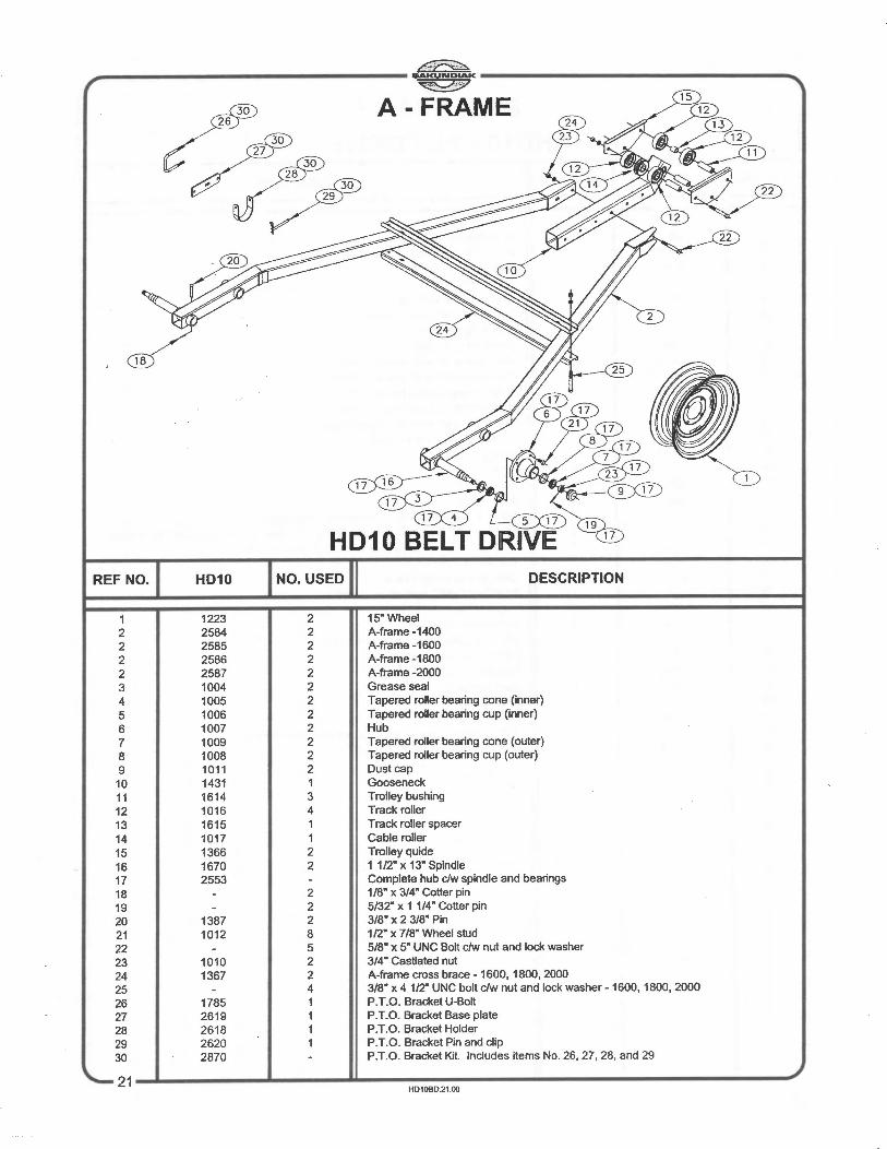
A- FRAME
2
18
17
HD10 BELT DRIVE REF NO. HD10 DESCRIPTION
1 1223 2 15" Wheel 2 2584 2 A-frame -1400 2 2585 2 A-frame -1600 2 2586 2 A-frame -1800 2 2587 2 A-frame -2000 3 1004 2 Grease seal 4 1005 2 Tapered roller bearing cone (inner)
5 1006 2 Tapered roller bearing cup (inner) 6 1007 2 Hub 7 1009 2 Tapered roller bearing cone (outer)
8 1008 2 Tapered roller bearing cup (outer) 9 1011 2 Dust cap 10 1431 1 Gooseneck 11 1614 3 Trolley bushing 12 1016 4 Track roller 13 1615 1 Track roller spacer
14 1017 1 Cable roller 15 1366 2 Trolley quide 16 1670 2 1 1/2" x 13" Spindle 17 2553 Complete hub clw spindle and bearings
18 2 1/8" x 3/4" Cotter pin
19 2 5/32" x 1 1/4" Cotter pin
20 1387 2 3/8" X 2 3/8" Pin
21 1012 8 1/2" x 7/8" Wheel stud
22 5 5/8" x 5" UNC Bolt c/w nut and lock washer
23 1010 2 3/4 • Castlated nut
24 1367 2 A-frame cross brace- 1600, 1800,2000
25 4 3/8" x 4 1/2" UNC bolt c!w nut and lock washer- 1600, 1800, 2000
26 1785 1 P.T.O. Bracket U-Bolt 27 2619 1 P.T.O. Bracket Base plate
28 2618 1 P.T.O. Bracket Holder 29 2620 1 P.T.O. Bracket Pin and clip
30 2870 P.T.O. Bracket Kit. Includes items No. 26, 27, 28, and 29
21 HD10BD.21.00

~ ~------------------ GAKUNDIAK ------------------......
~
MOTOR MOUNT ASSEMBLY
HD10 BELT DRIVE REF NO. HD10 DESCRIPTION
1587 Motor mount base 2 1590 2 Leveling bar bracket - lower 3 1588 2 Motor mount pivot bracket 4 2864 2 Motor mount bracket 5 1106 2 Pivot bushing 6 1107 1 Leveling bar adjusting screw- lower- LH. 7 2439 1 Leveling bar - 1400 7 1450 1 Leveling bar- 1600 7 1451 1 Leveling bar - 1800 7 1452 1 Leveling bar - 2000 8 1114 1 Leveling bar adjusting screw- upper- R.H. 9 3106 2 Leveling bar bracket- upper
10 2 1/4" x 1/2" Whiz bolt dw whiz nut 11 4 3/8" x 1" Carriage bolt c/w nut and lock washer 12 4 3/8" x 1 1/2" UNC bolt c/w nut and lock washer 13 2 3/8" x 2 3/4" UNC bolt c/w nut and lock washer 14 4 7/16" x 1" UNC bolt c/w nut and lock washer 15 2 7/16" x 3" UNC bolt c/w nut and lock washer 16 4 1/2" x 1 1/4" UNC bolt c/w nut and lock washer 17 1113 1 3/4" Jam nut- R.H. 18 2686 1 Engine pulley guard base 19 2687 1 Engine pulley guard 20 2964 1 Extension handle
~----~--------~------~-----------------------------------22 H0 10B0.22.00
l:
':! 0 "' 0 tl ~
28
26
.38
~~
~'
®
3
4
-1
c:
OJ
m
)>
en
en
m
s: OJ :~~
c ~
0 OJ
m
I -1
c :;o <
m

SAKUNDIAK
~ "''I
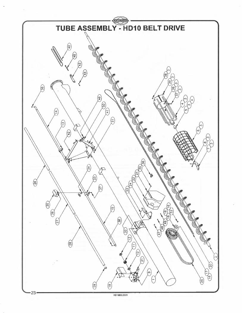
TUBE ASSEMBLY HD10 BELT DRIVE
REF NO. HD10 NO. USED II DESCRIPTION
1 1526 1 Tube assembly- 1400 1 1527 1 Tube assembly- 1600 1 1528 1 Tube assembly- 1800 1 1529 1 Tube assembly- 2000 2 1530 1 f'"light assembly- 1400 2 1531 1 Flight assembly - 1600 2 1532 1 Flight assembly- 1800 2 1533 1 Flight assembly- 2000 3 1534 - Intake fork- complete, includes Ref No.'s 4, 5, 6, 7, 8, 37, 38, 39 4 1535 1 Intake fork c/w bushing , includes Ref No.'s 4, 5 5 1536 - Intake fork bushing 6 1538 1 Intake guard 7 1539 1 Auger hitch 8 1646 1 Hitch pin and clip 9 1540 1 Gear box 11 1542 1 Coupler chain 12 1545 2 Coupler sprocket 13 1493 4 Pillow block bearing - 1400 13 1493 5 Pillow block bearing - 1600 13 1493 6 Pillow block bearing - 1800 13 1493 7 Pillow block bearing - 2000 14 1546 1 Drive shaft- top section -1400, 1600, 1800, 2000 15 1547 1 Drive shaft- bottom section- 1400 15 1548 1 Drive shaft- bottom section - 1600 15 1549 1 Drive shaft- bottom section- 1800 15 1550 1 Drive shaft- bottom section - 2000 16 1552 1 Triple groove V-pulley c/w hub 17 1553 - Triple groove V-pulley only 18 1554 - Pulley hub only 19 1555 2 Gear box shaft guard 20 1424 1 Lift cable - 1400 20 1425 1 Lift cable - 1600 20 1426 1 Lift cable - 1800 20 1556 1 Lift cable - 2000 21 1340 1 Pulley guard - front 22 1461 1 Pulley guard - back 23 1557 1 Pulley bracket- upper 24 1558 1 Pulley bracket - lower 25 1133 3 B-270 V-belt- 1400 ~5 1432 3 B-310 V-belt- 1600 25 1433 3 B-355 V-belt- 1800 25 1434 3 B-405 V-belt- 2000 26 1559 4 Drive shaft guard- top section- 1400 26 1559 5 Drive shaft guard- top section- 1600 26 1559 6 Drive shaft guard- top section- 1800 26 1559 7 Drive shaft guard -top section - 2000 27 2353 1 Drive shaft guard- middle section- 1400, 1600, 1800, 2000 28 1560 1 Drive shaft guard - bottom section - 1400 28 1561 1 Drive shaft guard- bottom section- 1600 28 1562 1 Drive shaft guard - bottom section - 1800 28 1563 1 Drive shaft guard - bottom section - 2000 29 1564 12 Drive shaft guard nylon bushing - 1400 29 1564 14 Drive shaft guard nylon bushing - 1600 29 1564 16 Drive shaft guard nylon bushing - 1800 29 1564 18 Drive shaft guard nylon bushing - 2000 30 - 3 1 /4" x 5/8" UNC Whiz bolt c/w whiz nut 31 - 3 3/8" x 1 1/4" Woodruff key 32 - 4 1 /2" x 3/4" UNC Whiz bolt 33 1409 1 Ball bearing insert 34 1410 1 Ball bearing housing 35 1704 1 Drive shaft bearing guard 36 2433 2 1/4" Cable clamp 37 - 10 3/8" x 1" Carriage bolt - 1400
24..-1 HD10BD.24.00

SAKUNDIAK , ~
"""' TUBE ASSEMBLY HD10 BELT DRIVE
REF NO. HD10 NO. USED II DESCRIPTION
37 - 12 3/8" x 1" Carriage bolt- 1600 37 - 14 3/8" x 1" Carriage bolt- 1800 37 - 16 3/8" x 1" Carriage bolt - 2000 38 - 20 3/8" Whiz nut - 1400 38 - 26 3/8" Whiz nut - 1600 38 - 28 3/8" Whiz nut - 1800 38 - 30 3/8" Whiz nut - 2000 39 - - 3/8" x 1" UNC Whiz bolt 40 1445 1 Truss cable- 1600 40 1567 1 Truss cable- 1800 40 1568 1 Truss cable- 2000 41 1443 2 Truss riser- 1600, 1800,2000 42 3102 1 Truss riser brace- 1600, 1800, 2000 43 1435 2 Truss tension bracket- 1600, 1800, 2000 44 - 4 1/2" UNC nut 45 - 2 1/2" x 6" UNC eyebolt 46 - 2 5/16" Cable clamp - 1600, 1800, 2000 47 - 2 1/4" x 5/8" Carriage bolt 48 - 4 1/4" UNC Whiz nut 49 - 1 1/4 • Wing nut 50 - 2 7/16" x 1" UNC Bolt cJw nut - 1600, 1800,2000 51 - 4 3/8" x 3/4 • Carriage bolt - 1400 51 - 8 3/8" x 3/4" Carriage bolt- 1600, 1800, 2000 52 - 3 Pulley hub bolt - 1956 - Decal "SAKUNDIAK" - 1572 - Decal "HD10-1400" - 1573 - Decal "HD10-1600" - 1574 - Decal "HD10-1800" - 1575 - Decal "HD10-2000" - 1569 - Auger flight 2" I. D. (per foot) - 1570 - Cupped flight 2" I. D. (per 2 feet) - 1571 - Auger tube 10" O.D. (per foot) - 1647 - Drive shaft tube 1-5/8" O.D. (per foot) - 1648 - Flight shaft tube 2" O.D. (per foot) - 1075 - Sakundiak red paint
- 2589 - Sakundiak grey paint - 2949 - Sakundiak red spray bomb paint - 2950 - Sakundiak grey spray bomb paint
"-2 .I 5 HD10BD.25.00

~ ~------------------------------------&AKUNDIAK------------------------------------~ ~
REF NO.
1 2 3 4 5
6-7-8 9
10 11 12 13 14 15
16-17 18
19-20 21
HD10
1576 1577 1578 1579 1586
1580 1581 1582 1461 1348 1349 1583
10
2
1 1 4 1 1 1 1 1 1 1 4 4 8 2
P.T.O. ATTACHMENT
14
5
BELT DRIVE
9
Note: 6" Pulley supplied with P.T.O. attachement, is to be assembled on the gear box. 11 1/2" Pulley supplied with auger is assembled on the P.T.O.
DESCRIPTION
PTO attachment base Bearing and casting complete Bearing - insert only Drive shaft Triple groove V-pulley complete with hub 1/2" x 1 3/4" UNC Bolt, nut, lockwasher Drive shaft guard PTO splined stub Mounting bracket- guard PTO guard - back PTO guard - front PTO spline guard Mounting bracket- guard 5/16" UNC Nut, lock washer 5/16" x 1" Carriage bolt 1/4" x 1/2" UNC whiz bolt, nut 1/4" x 1" Woodruff key
'-----~--------~------~------------------------------------26 HD10BD.26.00

cc:;::::;;, ~------------------------------------SAKUND~------------------------------------~ ~
PTO SHAFT
WEASLER 90" REF NO. HD10 DESCRIPTION
2004 1 Quick disconnect yoke 2 2005 1 Yoke repair kit 3 1996 1 Yoke and male shaft 4 1999 1 Outer PTO shield 5 1274 2 Cross and bearing kit 6 2003 1 Yoke and female tube 7 1998 2 Nylon bearing 8 2002 1 Shield centralizer 9 2001 1 Inner PTO shield 10 . 1988 1 Yoke repair kit- shear end 11 2008 2 Snap ring 12 1987 Quick disconnect shear yoke 13 2421 Safety decal 14 2423 Safety decal 15 1/4" x 1" Roll pin 16 2429 5/16" x 5/8" UNC Gr.2 bolt 17 2430 5/16" Nut
2036 Complete PTO shaft (#1140-90)
27~~----------------~-----------------------------------------' HD10BD.27.00

~ ~------------------------------------&AKUNDIAK------------------------------------~ ~
FULTON K2550 BRAKE WINCH
BELT DRIVE REF NO. HD10 DESCRIPTION
1 1672 Cable clamp 2 1711 Handle 3 1712 Pawl & spring 4 1933 Shaft brake disc 5 1934 1 Spacer 6 1937 3 Bushing 7 1939 1 Bushing 8 1943 1 Spring pin 9 1944 1 Output shaft 10 1946 1 Ratchet gear 11 1947 1 Pinion & disc 12 1948 2 Friction disc 13 2948 1 Input shaft 14 1 Drum bolt 15 1 Drum lock nut 16 1 Drum spacer 17 1 Drum assembly 18 1 Frame lock nut 19 2 Frame spacer 20 1 Frame bolt 21 1 Frame 22 1 Washer (input) 23 1 Washer (output) 24 2 Handle lock nut 25 Woodruff key 26 Gear 27 E-clip
28 HD1080.28.00
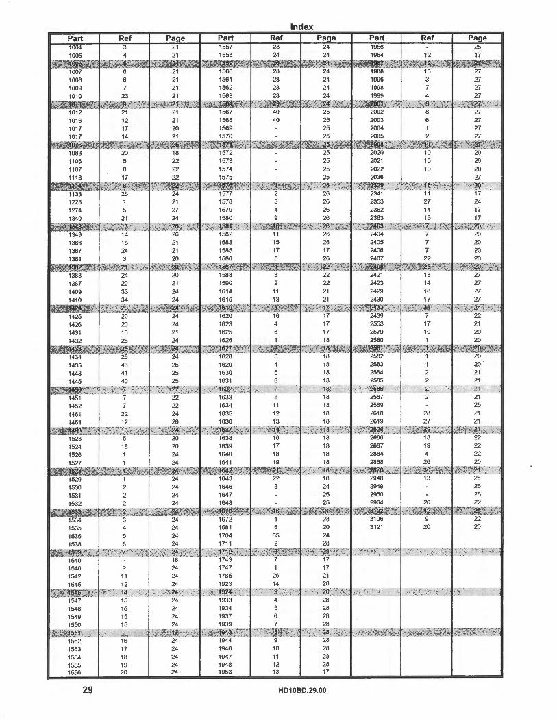
Part 1004 1005 1006 1007 1008 1009 1010
1 1012 1016
1409 1410
' ' •1424 1425 1426
1553 1554 1555 1556
29
Ref 3 4 5 6 8
12 17 14
20 5 6
17 18 19 20
Page 21
24 24 24 24
Part 1557
1946 1947 1948 1953
Ref 23
10 11 12 13
Index Page
24
28 28 28 17
HD10BD.29.00
Part Ref Page 25
20 20

~ ~-----------------------------------SAKUNDIAK----------------------------------~ ~
Limited Warranty Statement
Sakundiak Equipment Ltd. warrants each new Sakundiak Equipment Ltd. product to be free from defects in material and workmanship. This warranty is applicable only for the nonnal service life expectancy of the product or components, not to exceed twelve (12) consecutive months, or forty-five ( 45) days in the case of commercial use, from the date of delivery of the new Sakundiak Equipment Ltd. product to the original purchaser.
Genuine Sakundiak Equipment Ltd. replacement parts and components will be warranted for thirty (30) days from date of purchase, or the remainder of the original equipment warranty period, whichever is longer. Under no circumstances will Sakundiak Equipment Ltd. cover any merchandise or components thereof, which, in the opinion of Sakundiak Equipment Ltd., has been subjected to misuse, unauthorized modifications, alteration, an accident or if repairs have been made with parts other than those obtainable through Sakundiak Equipment Ltd.
Sakundiak Equipment Ltd. in no way warrants engines, batteries, tires or other trade accessories since these items are warranted separately by their respective manufacturer. Our obligation under this warranty shall be limited to repairing or replacing, free of charge to the original purchaser, any part that, in our judgment, shall show evidence of such defect, provided further that such part shall be returned within thirty (30) days from date of failure to Sakundiak Equipment Ltd., routed through the dealer and distributor from whom the purchase was made, transportation charges prepaid.
This warranty shall not be interpreted to render Sakundiak Equipment Ltd. liable for injury or damages of any kind or nature to person or property. This warranty does not extend to the loss of crops, loss because of delay in harvesting, or any expense or loss incurred for labor, substitute machinery, rental or for any other reason. Except as set forth above, Sakundiak Equipment Ltd. shaU have no obligation or liability of any kind on account of any of its equipment and shall not be liable for special or consequential damages.
Sakundiak Equipment Ltd. makes no other warranty, expressed or implied, and, specifically, Sakundiak Equipment Ltd. disclaims any implied warranty or merchantability or fitness for a particular purpose. Some states or provinces do not permit limitations or exclusions of implied warranties or incidental or consequential damages, so the limitations or exclusion in this warranty may not apply.
This warranty is subject to any existing conditions of supply which may directly affect our ability to obtain materials or manufacture replacement parts. Sakundiak Equipment Ltd. reserves the right to make improvements in design or changes in specifications at any time, without incurring any obligation to owners of units previously sold. No one is authorized to alter, modify or enlarge this warranty nor the exclusion, limitations and reservations.
~---------------------------------------------------------------------------------------30 HD1 0BD.30.01