ashrae 90.1-2004 mandatory provisions checklist...ashrae 90.1-2004 mandatory provisions checklist...
TRANSCRIPT

A mark of the Province of Ontario protected under Canadian trademark law. Used under sublicence. OMOfficial Mark of the Ontario Power Authority. Used under licence.
Version 1.0 – March 2011
Page 1 of 18
LDC LOGO HERE
ASHRAE 90.1-2004 Mandatory Provisions Checklist (as modified by Supplementary Standard SB-10) This form records whether all mandatory requirements of ASHRAE 90.1-2004 (ASHRAE 90.1) have been "met" or "not met" according to the information the simulator has received from the project's professional architect(s) and engineer(s). It is understood that design professionals are responsible for ensuring the energy code conformity itself. Simulators are responsible only for noting the conformity on this form. This form must be completed by the simulator and attached to the Compliance Report in the HPNC submission. Simulators are recommended to request and retain in their files, written records (typically emails or copies of checklist pages with professional's sign off etc.) that indicate the appropriate professional has verified that the requirement is "MET". In the case of conflict between this document, Supplementary Standard SB-10, or ANSI/ASHRAE/IESNA Standard 90.1, the full text of the applicable document governs. If a mandatory provision is "NOT MET", provide the reason why in the note section. Where an exemption has been granted by HPNC, check "NOT MET" and indicate in the note section where in the submission the exemption documentation can be found. If a mandatory is not applicable, check "NOT MET" and provide the reason why in the note section.
SCOPE
Applicability of ASHRAE 90.1 Met Not Met Building Type is not exempted under Section 2.3
Building type and spaces definition conforms with defined terms in Section 3.
Notes:

A mark of the Province of Ontario protected under Canadian trademark law. Used under sublicence. OMOfficial Mark of the Ontario Power Authority. Used under licence.
Version 1.0 – March 2011
Page 2 of 18
LDC LOGO HERE
Section 5 BUILDING ENVELOPE (taken entirely from SB-10)
5.4.1 Insulation Met Not Met Where no insulation is required in 5.5 or 5.6, it shall comply with the requirements found in 5.8.1.1 to 5.8.1.9.
5.4.2 Fenestration and Doors
Met Not Met Procedures for determining fenestration and door performance are described in 5.8.2. Product samples used for determining fenestration performance shall be production line units or representative of units purchased by the consumer or contractor.
5.4.3 Air Leakage
Met Not Met 5.4.3.1 Building Envelope Sealing The following areas of the building envelope shall be sealed, caulked, gasketed, or weather-stripped to minimize air leakage:
(a) joints around fenestration and door frames,
(b) junctions between walls and foundations, between walls at building corners, between walls and structural floors or roofs, and between walls and roof or wall panels,
(c) openings at penetrations of utility services through roof, walls, and floors,
(d) site-built fenestration and doors,
(e) building assemblies used as ducts or plenums
(f) joints, seams, and penetrations of vapour retarders
(g) all other openings in the building envelope
Met Not Met 5.4.3.2 Fenestration and Doors Except as provided in 5.4.3.2.4, where components of the air barrier system are covered in the scope of the standards listed below, the components shall conform to the requirements of the respective standards: (5.4.3.2.1)
(a) CAN/CGSB-63.14-M, “Plastic Skylights”,
(b) CAN/CGSB-82.1-M, “Sliding Doors”,
(c) CAN/CGSB-82.5-M, “Insulated Steel Doors”,
(d) CAN/CSA-A440-M, “Windows”.

A mark of the Province of Ontario protected under Canadian trademark law. Used under sublicence. OMOfficial Mark of the Ontario Power Authority. Used under licence.
Version 1.0 – March 2011
Page 3 of 18
LDC LOGO HERE
Skylights not covered in the scope of CAN/CGSB-63.14-M, “Plastic Skylights” shall conform, to the performance requirements of that standard. (5.4.3.2.2)
Except as provided in 5.4.3.2.4, windows and sliding doors covered in the scope of CAN/CGSB-82.1-M, “Sliding Doors”, and CAN/CSA-A440-M, “Windows” which are installed as components in an air barrier system shall conform at least to the airtightness requirements in CAN/CSA-A440.1, “User Selection Guide to CAN/CSA 440-00. Windows”. (5.4.3.2.3)
Where a wired glass assembly is installed as a component in an air barrier system in a required fire separation, the assembly need not conform to CAN/CSA-A440-M, “Windows” or CAN/CSA-A440.1, “User Selection Guide to CAN/CSA 440-00. Windows”. (5.4.3.2.4)
Met Not Met 5.4.3.3 Loading Dock Weatherseals Cargo doors and loading dock doors shall be equipped with weatherseals to restrict infiltration when vehicles are parked in the doorway.
Met Not Met 5.4.3.4 Vestibules A door that separates conditioned space from the exterior shall be protected with an enclosed vestibule, with all doors opening into and out of the vestibule equipped with self-closing devices. Vestibules shall be designed so that in passing through the vestibule it is not necessary for the interior and exterior doors to open at the same time.
Exceptions to 5.4.3.4: (a) Doors in buildings less than 5 storeys above grade. (b) Doors not intended to be used as a building entrance door, such as doors to mechanical or electrical equipment rooms.
(c) Doors opening directly from a dwelling unit. (d) Doors that open directly from a space less than 279 m2 (3000 ft2) in area. (e) Doors in building entrances with revolving doors. (f) Doors used primarily to facilitate vehicular movement or material handling and adjacent personnel doors.
(g) Doors intended to be used as a service or emergency exit door only.

A mark of the Province of Ontario protected under Canadian trademark law. Used under sublicence. OMOfficial Mark of the Ontario Power Authority. Used under licence.
Version 1.0 – March 2011
Page 4 of 18
LDC LOGO HERE
Section 6 HEATING, VENTILATION AND AIR CONDITIONING
6.4 Mandatory Provisions
6.4.1 Equipment Efficiencies, Verification, and Labeling Requirements Met Not Met 6.4.1.1 Minimum Equipment Efficiencies – Listed Equipment – Standard Rating and Operating Conditions (modified by SB-10) Equipment shown in Tables 6.8.1A to 6.8.1G shall have a minimum performance at the specified rating conditions when tested in accordance with the specified test procedure. The minimum efficiency values, test procedures and standards specified in the Ontario Energy Efficiency Act shall apply if provided. Otherwise, the minimum efficiency values, test procedures and standards specified in ANSI/ASHRAE/IESNA Standard 90.1 shall apply. When multiple rating conditions or performance requirements are provided, the equipment shall satisfy all requirements, unless otherwise exempted by footnotes in the table. Equipment regulated under the Ontario Energy Efficiency Act shall have no minimum efficiency requirements for operation at minimum capacity or other than standard rating conditions. Equipment used to provide water eating functions as part of a combination system shall satisfy all requirements for the appropriate space heating or cooling category.
Tables are as follows:
(a) Table 6.8.1A – Air Conditioners and Condensing Units
(b) Table 6.8.1B – Heat Pumps
(c) Table 6.8.1C – Water Chilling Packages (see 6.4.1.2 for water-cooled centrifugal water-chilling packages designed to operate at nonstandard conditions)
(d) Table 6.8.1D – Packaged Terminal and Room Air Conditioners and Heat Pumps
(e) Table 6.8.1E – Furnaces, Duct Furnaces and Unit Heaters
(f) Table 6.8.1F – Boilers
(g) Table 6.8.1G – Heat Rejection Equipment
All furnaces with input ratings of >66 kW (>225,000 Btu/hr), including electric furnaces, that are not located within the conditioned space shall have jacket losses not exceeding 0.75% of the input rating.
Met Not Met 6.4.1.2 Minimum Equipment Efficiencies – Listed Equipment – Nonstandard Conditions Water-cooled centrifugal water-chilling packages that are not designed for operation at ARI Standard 550/590 test conditions (and thus cannot be tested to meet the requirements of Table 6.8.1C) of 44°F leaving chilled water temperature and 85°F entering condenser water temperature with 3 gpm/ton condenser water flow shall have a minimum full-load COP and a minimum NPLV rating as shown in the tables referenced below.
(a) Centrifugal chillers <150 tons shall meet the minimum full-load COP and IPLV/NPLV in Table 6.8.1H.

A mark of the Province of Ontario protected under Canadian trademark law. Used under sublicence. OMOfficial Mark of the Ontario Power Authority. Used under licence.
Version 1.0 – March 2011
Page 5 of 18
LDC LOGO HERE
(b) Centrifugal chillers >150 tons and <300 tons shall meet the minimum full-load COP and IPLV/NPLV in Table 6.8.1I.
(c) Centrifugal chillers >300 tons shall meet the minimum full-load COP and IPLV/NPLV in Table 6.8.1J.
The table values are only applicable over the following full-load design values:
Leaving Chiller Water Temperature: 40°F to 48°F
Entering Condenser Water Temperature: 75°F to 85°F
Condensing Water Temperature Rise: 5°F to 15°F
Chiller designed to operate outside of these ranges or applications utilizing fluids or solutions with secondary coolants (e.g. glycol solutions or brines) with a freeze point of 27F or less for freeze protection are not covered by this standard.
Met Not Met 6.4.1.3 Equipment Not Listed Equipment not listed in the tables referenced in 6.4.1.1 and 6.4.1.2 may be used.
Met Not Met 6.4.1.4 Verification of Equipment Efficiencies (modified by SB-10) Equipment efficiency information supplied by manufacturers shall be verified as follows:
(a) Equipment covered under the Ontario Energy Efficiency Act shall comply with U.S. Ontario Ministry of Energy certification requirements.
(b) If a certification program exists for a covered product, and it includes provisions for verification and challenge of equipment efficiency ratings, then the product shall be listed in the certification program, or
(c) if a certification program exists for a covered product, and it includes provisions for verification and challenge of equipment efficiency ratings, but the product is not listed in the existing certification program, the ratings shall be verified by an independent laboratory test report, or
(d) if no certification program exists for a covered product, the equipment efficiency ratings shall be supported by data furnished by the manufacturer, or
e) where components such as indoor or outdoor coils from different manufacturers are used, the system designer shall specify component efficiencies whose combined efficiency meets the minimum equipment efficiency requirements in 6.4.1.
f) Products covered in Table 6.8.1G shall have efficiency ratings supported by data furnished by the manufacturer.
Met Not Met 6.4.1.5 Labeling (modified by SB-10)
6.4.1.5.1 Mechanical Equipment. Mechanical equipment that is regulated by the Ontario Energy Efficiency Act shall carry a permanent label installed by the manufacturer stating that the equipment complies with the requirements of ASHRAE/IESNA Standard 90.1.
Equipment Ratings . Equipment ratings certified under a nationally recognized certification program or rating procedure or data furnished by the equipment manufacturer shall be acceptable to satisfy these requirements. The equipment efficiencies must be tested in accordance with the appropriate Reference Standards as listed in Tables 10-1 to 10-10 to be acceptable.
A mark of the Province of Ontario protected under Canadian trademark law. Used under sublicence. OMOfficial Mark of the Ontario Power Authority. Used under licence.
Version 1.0 – March 2011
Page 6 of 18
LDC LOGO HERE
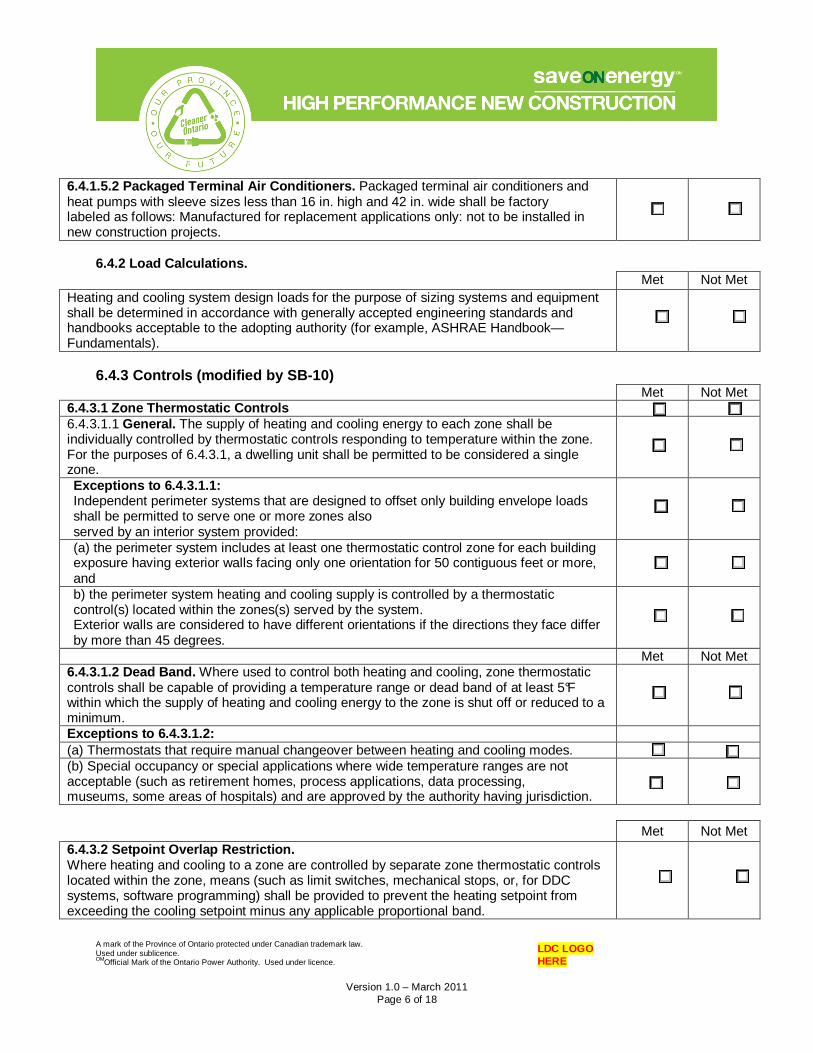
6.4.1.5.2 Packaged Terminal Air Conditioners. Packaged terminal air conditioners and heat pumps with sleeve sizes less than 16 in. high and 42 in. wide shall be factory labeled as follows: Manufactured for replacement applications only: not to be installed in new construction projects.
6.4.2 Load Calculations.
Met Not Met Heating and cooling system design loads for the purpose of sizing systems and equipment shall be determined in accordance with generally accepted engineering standards and handbooks acceptable to the adopting authority (for example, ASHRAE Handbook—Fundamentals).
6.4.3 Controls (modified by SB-10)
Met Not Met 6.4.3.1 Zone Thermostatic Controls 6.4.3.1.1 General. The supply of heating and cooling energy to each zone shall be individually controlled by thermostatic controls responding to temperature within the zone. For the purposes of 6.4.3.1, a dwelling unit shall be permitted to be considered a single zone.
Exceptions to 6.4.3.1.1: Independent perimeter systems that are designed to offset only building envelope loads shall be permitted to serve one or more zones also served by an interior system provided:
(a) the perimeter system includes at least one thermostatic control zone for each building exposure having exterior walls facing only one orientation for 50 contiguous feet or more, and
b) the perimeter system heating and cooling supply is controlled by a thermostatic control(s) located within the zones(s) served by the system. Exterior walls are considered to have different orientations if the directions they face differ by more than 45 degrees.
Met Not Met 6.4.3.1.2 Dead Band. Where used to control both heating and cooling, zone thermostatic controls shall be capable of providing a temperature range or dead band of at least 5°F within which the supply of heating and cooling energy to the zone is shut off or reduced to a minimum.
Exceptions to 6.4.3.1.2: (a) Thermostats that require manual changeover between heating and cooling modes. (b) Special occupancy or special applications where wide temperature ranges are not acceptable (such as retirement homes, process applications, data processing, museums, some areas of hospitals) and are approved by the authority having jurisdiction.
Met Not Met 6.4.3.2 Setpoint Overlap Restriction. Where heating and cooling to a zone are controlled by separate zone thermostatic controls located within the zone, means (such as limit switches, mechanical stops, or, for DDC systems, software programming) shall be provided to prevent the heating setpoint from exceeding the cooling setpoint minus any applicable proportional band.

A mark of the Province of Ontario protected under Canadian trademark law. Used under sublicence. OMOfficial Mark of the Ontario Power Authority. Used under licence.
Version 1.0 – March 2011
Page 7 of 18
LDC LOGO HERE
Met Not Met
(a) Off-Hour Controls. HVAC systems shall have the off-hour controls required by Sections 6.4.3.3.1 through 6.4.3.3.4.
Exceptions to 6.4.3.2:
(a) HVAC systems serving hotel/motel guest rooms.
(b) HVAC systems intended to operate continuously.
(c) HVAC systems having a design heating capacity and cooling capacity less than 15,000 Btu/h that are equipped with readily accessible manual on/off controls.
6.4.3.2.1 Automatic Shutdown . HVAC systems shall be equipped with at least one of the following:
(a) Controls that can start and stop the system under different time schedules for seven different day-types per week, are capable of retaining programming and time setting during loss of power for a period of at least 10 hours, and include an accessible manual override, or equivalent function, that allows temporary operation of the system for up to two hours.
(b) An occupant sensor that is capable of shutting the system off when no occupant is sensed for a period of up to 30 minutes.
(c) A manually operated timer capable of being adjusted to operate the system for up to two hours.
(d) An interlock to a security system that shuts the system off when the security system is activated.
Exception to 6.4.3.2.1: Residential occupancies may use controls that can start and stop the system under two different time schedules per week.
6.4.3.3.2 Setback Controls. Heating systems located in climate zones 2-8 shall be equipped with controls that have the capability to automatically restart and temporarily operate the system as required to maintain zone temperatures above a heating setpoint adjustable down to 55°F or lower. Cooling systems lo cated in climate zones 1b, 2b, and 3b shall be equipped with controls that have the capability to automatically restart and temporarily operate the system as required to maintain zone temperatures below a cooling setpoint adjustable up to 90°F or higher or to prev ent high space humidity levels.
Met Not Met Exception to 6.4.3.2.2: Radiant floor and ceiling heating systems. 6.4.3.2.3 Optimum Start Controls. Individual heating and cooling air distribution systems with a total design supply air capacity exceeding 10,000 cfm, served by one or more supply fans, shall have optimum start controls. The control algorithm shall, as a minimum, be a function of the difference between space temperature and occupied setpoint and the amount of time prior to scheduled occupancy.

A mark of the Province of Ontario protected under Canadian trademark law. Used under sublicence. OMOfficial Mark of the Ontario Power Authority. Used under licence.
Version 1.0 – March 2011
Page 8 of 18
LDC LOGO HERE
6.4.3.2.4 Zone Isolation. HVAC systems serving zones that are intended to operate or be occupied non-simultaneously shall be divided into isolation areas. Zones may be grouped into a single isolation area provided it does not exceed 25,000 ft2 of conditioned floor area nor include more than one floor. Each isolation area shall be equipped with isolation devices capable of automatically shutting off the supply of conditioned air and outdoor air to and exhaust air from the area. Each isolation area shall be controlled independently by a device meeting the requirements of 6.4.3.3.1 (Automatic Shutdown). For central systems and plants, controls and devices shall be provided to allow stable system and equipment operation for any length of time while serving only the smallest isolation area served by the system or plant.
Exceptions to 6.4.3.2.4: Isolation devices and controls are not required for the following: (a) Exhaust air and outdoor air connections to isolation zones when the fan system to which they connect is 5000 cfm and smaller.
(b) Exhaust airflow from a single isolation zone of less than 10% of the design airflow of the exhaust system to which it connects.
(c) Zones intended to operate continuously or intended to be inoperative only when all other zones are inoperative.
Met Not Met 6.4.3.3 Ventilation System Controls. (Modified by S B-10) 6.4.3.3.1 Stair and Shaft Vents. Stair and elevator shaft vents shall be equipped with motorized dampers that are capable of being automatically closed during normal building operation and are interlocked to open as required by fire and smoke detection systems.
6.4.3.3.2 Gravity Hoods, Vents, and Ventilators. All outdoor air supply and exhaust hoods, vents, and ventilators shall be equipped with motorized dampers that will automatically shut when the spaces served are not in use.
Exceptions to 6.4.3.3.1 and 6.4.3.3.2: (a) Gravity (non-motorized) dampers are acceptable in buildings less than three stories in height above grade and for buildings of any height located in climate zones 1, 2, and 3.
(b) Ventilation systems serving unconditioned spaces. 6.4.3.3.3 Shutoff Damper Controls. Both outdoor air supply and exhaust systems shall be equipped with motorized dampers that will automatically shut when the systems or spaces served are not in use. Ventilation outdoor air dampers shall be capable of automatically shutting off during preoccupancy building warm-up, cool down, and setback, except when ventilation reduces energy costs (e.g., night purge) or when ventilation must be supplied to meet code requirements.
Exceptions to 6.4.3.3.3: (a) Gravity (non-motorized) dampers are acceptable in buildings less than three stories in height and for buildings of any height located in climate zones 1, 2, and 3.
(b) Gravity (non-motorized) dampers are acceptable in systems with a design outdoor air intake or exhaust capacity of 300 cfm or less.
6.4.3.3.4 Dampers. Where outdoor air supply and exhaust air dampers are required by Section 6.4.3.4, they shall have a maximum leakage rate when tested in accordance with AMCA Standard 500 as indicated in Table 6.4.3.4.4.

A mark of the Province of Ontario protected under Canadian trademark law. Used under sublicence. OMOfficial Mark of the Ontario Power Authority. Used under licence.
Version 1.0 – March 2011
Page 9 of 18
LDC LOGO HERE
Climate Zones Motorized Nonmotorized1, 2, 6, 7, 8 4 Not AllowedAll Others 10 20a
Maximum Damper Leakage at 1.0
in. w.g., cfm per ft 2 of damper area
TABLE 6.4.3.3.4 Maximum Damper Leakage
a Dampers smaller than 24 in. in either dimension may have
leakage of 40 cfm/ft2.
Met Not Met 6.4.3.4 Heat Pump Auxiliary Heat Control. Heat pumps equipped with internal electric resistance heaters shall have controls that prevent supplemental heater operation when the heating load can be met by the heat pump alone during both steady-state operation and setback recovery. Supplemental heater operation is permitted during outdoor coil defrost cycles.
Exception to 6.4.3.4: Heat pumps whose minimum efficiency is regulated by the Ontario Energy Efficiency Act and whose HSPF rating both meets the requirements shown in Table 6.8.1B and includes all usage of internal electric resistance heating.
Met Not Met 6.4.3.5 Humidifier Preheat. Humidifiers with preheating jackets mounted in the airstream shall be provided with an automatic valve to shut off preheat when humidification is not required.
Met Not Met 6.4.3.6 Humidification and Dehumidification. Where a zone is served by a system or systems with both humidification and dehumidification capability, means (such as limit switches, mechanical stops, or, for DDC systems, software programming) shall be provided capable of preventing simultaneous operation of humidification and dehumidification equipment.
Exceptions to 6.4.3.6: (a) Zones served by desiccant systems, used with direct evaporative cooling in series.
(b) Systems serving zones where specific humidity levels are required, such as computer rooms, museums, and hospitals, and approved by the authority having jurisdiction.
Met Not Met 6.4.3.3.5 Ventilation Fan Controls. Fans with motors greater than ¾ hp (0.5 kW) shall have automatic controls complying with Section 6.4.3.3.1 that are capable of shutting off fans when not required.
Exception to 6.4.3.3.5: HVAC systems intended to operate continuously.

A mark of the Province of Ontario protected under Canadian trademark law. Used under sublicence. OMOfficial Mark of the Ontario Power Authority. Used under licence.
Version 1.0 – March 2011
Page 10 of 18
LDC LOGO HERE
Met Not Met 6.4.3.7 Freeze Protection and Snow/Ice Melting Syste ms. Freeze protection systems, such as heat tracing of outdoor piping and heat exchangers, including self-regulating heat tracing, shall include automatic controls capable of shutting off the systems when outdoor air temperatures are above 40°F or when the conditions o f the protected fluid will prevent freezing. Snow- and ice-melting systems shall include automatic controls capable of shutting off the systems when the pavement temperature is above 50°F and no precipitation is falling and an automatic or manual control that will allow shutoff when the outdoor temperature is above 40°F so that the p otential for snow or ice accumulation is negligible.
Met Not Met 6.4.3.8 Ventilation Controls for High-Occupancy Are as. Systems with design outdoor air capacities greater than 3000 cfm serving areas having an average design occupancy density exceeding 100 people per 1000 ft2 shall include means to automatically reduce outdoor air intake below design rates when spaces are partially occupied. Ventilation controls shall be in compliance with ASHRAE Standard 62 and local standards.
Exception to 6.4.3.8: Systems with energy recovery complying with 6.5.6.1.
6.4.4 HVAC System Construction and Insulation
Met Not Met 6.4.4.1 Insulation 6.4.4.1.1 General. Insulation required by this section shall be installed in accordance with industry-accepted standards (see Appendix E). These requirements do not apply to HVAC equipment. Insulation shall be protected from damage, including that due to sunlight, moisture, equipment maintenance and wind, but not limited to the following:
(a) Insulation exposed to weather shall be suitable for outdoor service, e.g., protected by aluminum, sheet metal, painted canvas, or plastic cover. Cellular foam insulation shall be protected as above or painted with a coating that is water retardant and provides shielding from solar radiation that can cause degradation of the material.
(b) Insulation covering chilled water piping, refrigerant suction piping, or cooling ducts located outside the conditioned space shall include a vapor retardant located outside the insulation (unless the insulation is inherently vapor retardant), all penetrations and joints of which shall be sealed.
6.4.4.1.2 Duct and Plenum Insulation. All supply and return ducts and plenums installed as part of an HVAC air distribution system shall be thermally insulated in accordance with Tables 6.8.2A and 6.8.2B.
Exceptions to 6.4.4.1.2: (a) Factory-installed plenums, casings, or ductwork furnished as a part of HVAC equipment tested and rated in accordance with 6.4.1.
(b) Ducts or plenums located in heated spaces, semiheated spaces, or cooled spaces.
(c) For runouts less than 10 ft in length to air terminals or air outlets, the rated R-value of insulation need not exceed R-3.5.
(d) Backs of air outlets and outlet plenums exposed to unconditioned or indirectly conditioned spaces with face areas exceeding 5 ft2 need not exceed R-2; those 5 ft2 or smaller need not be insulated.

A mark of the Province of Ontario protected under Canadian trademark law. Used under sublicence. OMOfficial Mark of the Ontario Power Authority. Used under licence.
Version 1.0 – March 2011
Page 11 of 18
LDC LOGO HERE
6.4.4.1.3 Piping Insulation. Piping shall be thermally insulated in accordance with Table 6.8.3.
Exceptions to 6.4.4.1.3:
(a) Factory-installed piping within HVAC equipment tested and rated in accordance with 6.4.1.
(b) Piping that conveys fluids having a design operating temperature range between 60°F and 105°F, inclusive.
(c) Piping that conveys fluids that have not been heated or cooled through the use of nonrenewable energy (such as roof and condensate drains, domestic cold water supply, natural gas piping, or refrigerant liquid piping) or where heat gain or heat loss will not increase energy usage.
(d) Hot water piping between the shutoff valve and the coil, not exceeding 4 ft in length, when located in conditioned spaces.
(e) Pipe unions in heating systems (steam, steam condensate, and hot water).
Met Not Met 6.4.4.2 Ducts and Plenum Leakage 6.4.4.2.1 Duct Sealing. Ductwork and plenums shall be sealed in accordance with Table 6.4.4.2A (Table 6.4.4.2B provides definitions of seal levels), as required to meet the requirements of 6.4.4.2.2 and with standard industry practice (see Appendix E).
Duct LocationExhaust Return
≤2 in. w.c.b ≥2 in. w.c.b
Outdoor A A C A Unconditioned Space B A C BConditioned Spacesc C B B Ca See Table 6.4.4.2B description of seal levelb Duct design static pressure classificationc Includes indirectly conditioned spaces such as return air plenums
SupplyDuct Type
TABLE 6.4.4.2A Minimum Duct Seal Level a
A mark of the Province of Ontario protected under Canadian trademark law. Used under sublicence. OMOfficial Mark of the Ontario Power Authority. Used under licence.
Version 1.0 – March 2011
Page 12 of 18
LDC LOGO HERE
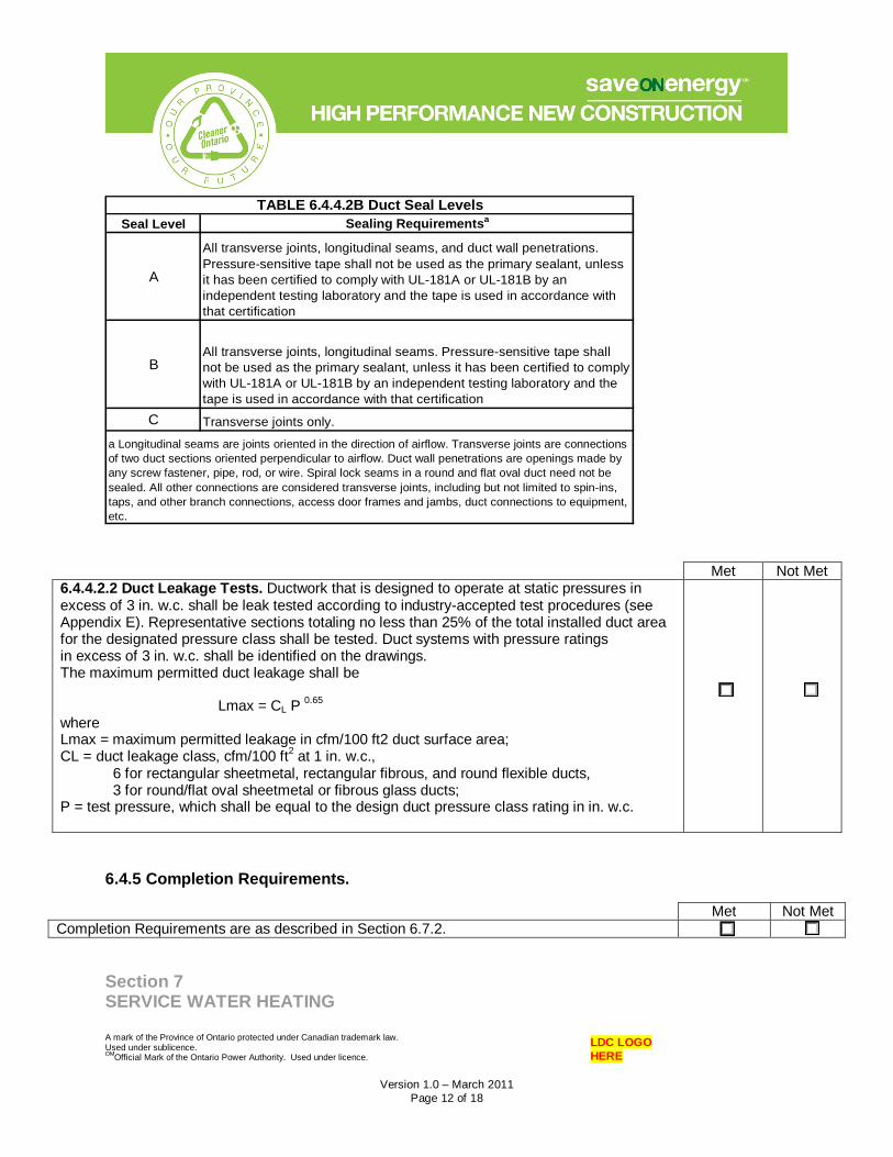
Seal Level Sealing Requirements a
A
All transverse joints, longitudinal seams, and duct wall penetrations. Pressure-sensitive tape shall not be used as the primary sealant, unless it has been certified to comply with UL-181A or UL-181B by an independent testing laboratory and the tape is used in accordance with that certification
BAll transverse joints, longitudinal seams. Pressure-sensitive tape shall not be used as the primary sealant, unless it has been certified to comply with UL-181A or UL-181B by an independent testing laboratory and the tape is used in accordance with that certification
C Transverse joints only.
a Longitudinal seams are joints oriented in the direction of airflow. Transverse joints are connections of two duct sections oriented perpendicular to airflow. Duct wall penetrations are openings made by any screw fastener, pipe, rod, or wire. Spiral lock seams in a round and flat oval duct need not be sealed. All other connections are considered transverse joints, including but not limited to spin-ins, taps, and other branch connections, access door frames and jambs, duct connections to equipment, etc.
TABLE 6.4.4.2B Duct Seal Levels
Met Not Met 6.4.4.2.2 Duct Leakage Tests. Ductwork that is designed to operate at static pressures in excess of 3 in. w.c. shall be leak tested according to industry-accepted test procedures (see Appendix E). Representative sections totaling no less than 25% of the total installed duct area for the designated pressure class shall be tested. Duct systems with pressure ratings in excess of 3 in. w.c. shall be identified on the drawings. The maximum permitted duct leakage shall be
Lmax = CL P 0.65 where Lmax = maximum permitted leakage in cfm/100 ft2 duct surface area; CL = duct leakage class, cfm/100 ft2 at 1 in. w.c.,
6 for rectangular sheetmetal, rectangular fibrous, and round flexible ducts, 3 for round/flat oval sheetmetal or fibrous glass ducts;
P = test pressure, which shall be equal to the design duct pressure class rating in in. w.c.
6.4.5 Completion Requirements.
Section 7 SERVICE WATER HEATING
Met Not Met Completion Requirements are as described in Section 6.7.2.
A mark of the Province of Ontario protected under Canadian trademark law. Used under sublicence. OMOfficial Mark of the Ontario Power Authority. Used under licence.
Version 1.0 – March 2011
Page 13 of 18
LDC LOGO HERE
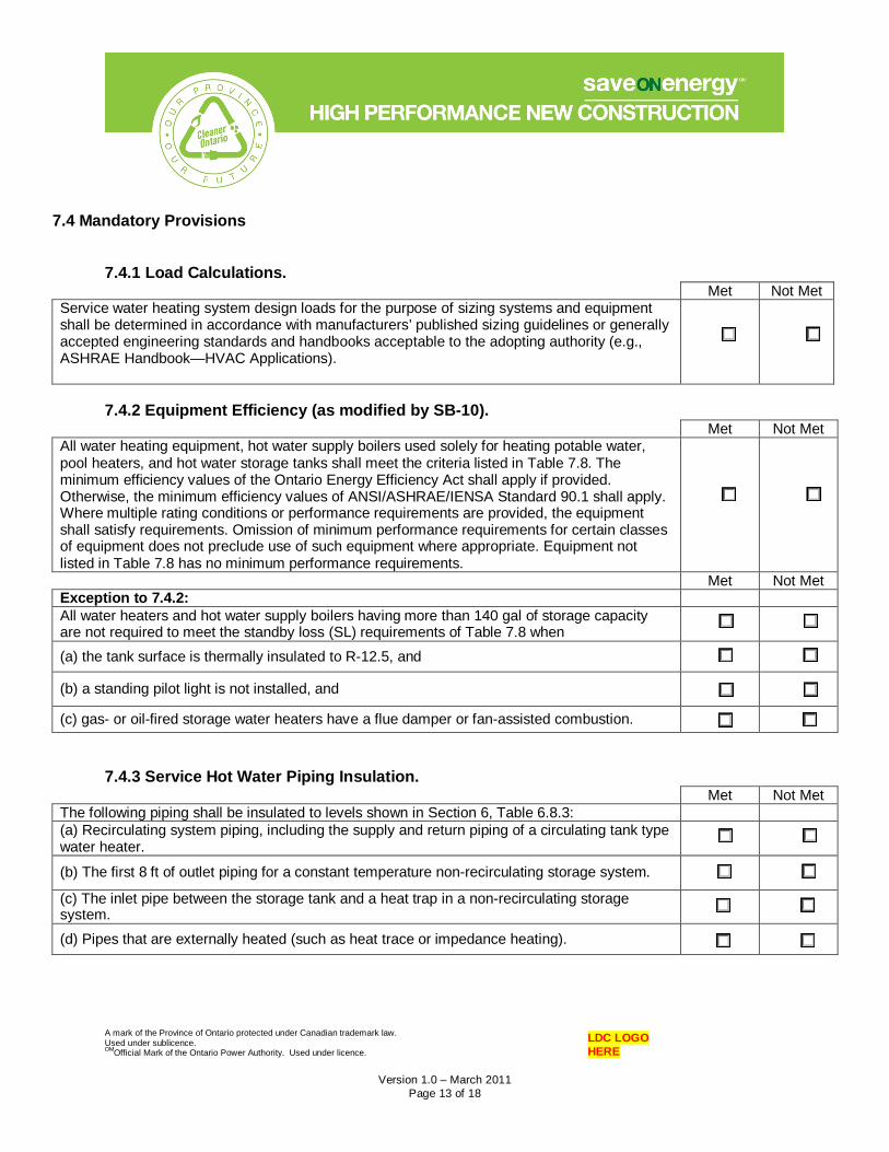
7.4 Mandatory Provisions
7.4.1 Load Calculations. Met Not Met Service water heating system design loads for the purpose of sizing systems and equipment shall be determined in accordance with manufacturers’ published sizing guidelines or generally accepted engineering standards and handbooks acceptable to the adopting authority (e.g., ASHRAE Handbook—HVAC Applications).
7.4.2 Equipment Efficiency (as modified by SB-10).
Met Not Met All water heating equipment, hot water supply boilers used solely for heating potable water, pool heaters, and hot water storage tanks shall meet the criteria listed in Table 7.8. The minimum efficiency values of the Ontario Energy Efficiency Act shall apply if provided. Otherwise, the minimum efficiency values of ANSI/ASHRAE/IENSA Standard 90.1 shall apply. Where multiple rating conditions or performance requirements are provided, the equipment shall satisfy requirements. Omission of minimum performance requirements for certain classes of equipment does not preclude use of such equipment where appropriate. Equipment not listed in Table 7.8 has no minimum performance requirements.
Met Not Met Exception to 7.4.2: All water heaters and hot water supply boilers having more than 140 gal of storage capacity are not required to meet the standby loss (SL) requirements of Table 7.8 when
(a) the tank surface is thermally insulated to R-12.5, and
(b) a standing pilot light is not installed, and
(c) gas- or oil-fired storage water heaters have a flue damper or fan-assisted combustion.
7.4.3 Service Hot Water Piping Insulation.
Met Not Met The following piping shall be insulated to levels shown in Section 6, Table 6.8.3: (a) Recirculating system piping, including the supply and return piping of a circulating tank type water heater.
(b) The first 8 ft of outlet piping for a constant temperature non-recirculating storage system.
(c) The inlet pipe between the storage tank and a heat trap in a non-recirculating storage system.
(d) Pipes that are externally heated (such as heat trace or impedance heating).

A mark of the Province of Ontario protected under Canadian trademark law. Used under sublicence. OMOfficial Mark of the Ontario Power Authority. Used under licence.
Version 1.0 – March 2011
Page 14 of 18
LDC LOGO HERE
7.4.4 Service Water Heating System Controls Met Not Met 7.4.4.1 Temperature Controls. Temperature controls shall be provided that allow for storage temperature adjustment from 120°F or lower to a maximum temperature compatible wi th the intended use.
Exception to 7.4.4.1: When the manufacturer's installation instructions specify a higher minimum thermostat setting to minimize condensation and resulting corrosion.
Met Not Met 7.4.4.2 Temperature Maintenance Controls. Systems designed to maintain usage temperatures in hot water pipes, such as recirculating hot water systems or heat trace, shall be equipped with automatic time switches or other controls that can be set to switch off the usage temperature maintenance system during extended periods when hot water is not required.
Met Not Met 7.4.4.3 Outlet Temperature Controls (modified by SB-10) Temperature controlling means shall be provided to limit the maximum temperature of water delivered from lavatory faucets in public facility restrooms to 110°F. The water outlet temperature refers only to the water temperature supplied to the fixture. It has no implication on the source temperature of the water which may be tempered by temperature gauges and control devices before it is supplied to the fixture.
Met Not Met 7.4.4.4 Circulating Pump Controls. When used to maintain storage tank water temperature, recirculating pumps shall be equipped with controls limiting operation to a period from the start of the heating cycle to a maximum of five minutes after the end of the heating cycle.
7.4.5 Pools
Met Not Met 7.4.5.1 Pool Heaters. Pool heaters shall be equipped with a readily accessible on-off switch to allow shutting off the heater without adjusting the thermostat setting. Pool heaters fired by natural gas shall not have continuously burning pilot lights.
Met Not Met 7.4.5.2 Pool Covers (as modified by SB-10). Heated exterior swimming pools (including lap pools and permanent whirlpools) shall be equipped with pool covers.
Exception to 7.4.5.2: Pools deriving over 60% of the energy for heating (computed over an annual operating season) from site-recovered or site- solar energy.

A mark of the Province of Ontario protected under Canadian trademark law. Used under sublicence. OMOfficial Mark of the Ontario Power Authority. Used under licence.
Version 1.0 – March 2011
Page 15 of 18
LDC LOGO HERE
Met Not Met 7.4.5.3 Time Switches. Time switches shall be installed on swimming pool heaters and pumps.
Exceptions to 7.4.5.3:
(a) Where public health standards require 24-hour pump operation.
(b) Where pumps are required to operate solar and waste heat recovery pool heating systems.
7.4.6 Heat Traps.
Met Not Met Vertical pipe risers serving storage water heaters and storage tanks not having integral heat traps and serving a non-recirculating system shall have heat traps on both the inlet and outlet piping as close as practical to the storage tank. A heat trap is a means to counteract the natural convection of heated water in a vertical pipe run. The means is either a device specifically designed for the purpose or an arrangement of tubing that forms a loop of 360 degrees or piping that from the point of connection to the water heater (inlet or outlet) includes a length of piping directed downward before connection to the vertical piping of the supply water or hot water distribution system, as applicable.
Section 8 POWER 8.4.1 Voltage Drop
Met Not Met 8.4.1.1 Feeders. Feeder conductors shall be sized for a maximum voltage drop of 2% at design load.
Met Not Met 8.4.1.2 Branch Circuits. Branch circuit conductors shall be sized for a maximum voltage drop of 3% at design load.
Section 9 LIGHTING 9.4.1 Lighting Control
Met Not Met 9.4.1.1 Automatic Lighting Shutoff. Interior lighting in buildings larger than 5000 ft2 shall be controlled with an automatic control device to shut off building lighting in all spaces. This automatic control device shall function on either
(a) a scheduled basis using a time-of-day operated control device that turns lighting off at specific programmed times—an independent program schedule shall be provided for areas of no more than 25,000 ft2 but not more than one floor—or

A mark of the Province of Ontario protected under Canadian trademark law. Used under sublicence. OMOfficial Mark of the Ontario Power Authority. Used under licence.
Version 1.0 – March 2011
Page 16 of 18
LDC LOGO HERE
(b) an occupant sensor that shall turn lighting off within 30 minutes of an occupant leaving a space—or
(c) a signal from another control or alarm system that indicates the area is unoccupied.
Exceptions to 9.4.1.1:
The following shall not require an automatic control device:
(a) Lighting intended for 24-hour operation
(b) Lighting in spaces where patient care is rendered.
(c) Spaces where an automatic shutoff would endanger the safety or security of the room or building occupant(s).
Met Not Met 9.4.1.2 Space Control. Each space enclosed by ceiling height partitions shall have at least one control device to independently control the general lighting within the space. Each manual device shall be readily accessible and located so the occupants can see the controlled lighting.
(a) A control device shall be installed that automatically turns lighting off within 30 minutes of all occupants leaving a space, except spaces with multi-scene control, in
1. classrooms (not including shop classrooms, laboratory classrooms, and preschool through 12th grade classrooms),
2. conference/meeting rooms,
3. employee lunch and break rooms.
These spaces are not required to be connected to other automatic lighting shutoff controls.
(b) For all other spaces, each control device shall be activated either manually by an occupant or automatically by sensing an occupant. Each control device shall control a maximum of 2500 ft2 area for a space 10,000 ft2 or less and a maximum of 10,000 ft2 area for a space greater than 10,000 ft2 and be capable of overriding any time-of-day scheduled shutoff control for no more than four hours.
Exception to 9.4.1.2: Remote location shall be permitted for reasons of safety or security when the remote control device has an indicator pilot light as part of or next to the control device and the light is clearly labeled to identify the controlled lighting.
Met Not Met 9.4.1.3 Exterior Lighting Control. Lighting for all exterior applications not exempted in 9.1 shall have automatic controls capable of turning off exterior lighting when sufficient daylight is available or when the lighting is not required during nighttime hours. Lighting not designated for dusk-to-dawn operation shall be controlled by an astronomical time switch. Lighting designated for dusk-to-dawn operation shall be controlled by an astronomical time switch or photosensor. Astronomical time switches shall be capable of retaining programming and the time setting during loss of power for a period of at least 10 hours.

A mark of the Province of Ontario protected under Canadian trademark law. Used under sublicence. OMOfficial Mark of the Ontario Power Authority. Used under licence.
Version 1.0 – March 2011
Page 17 of 18
LDC LOGO HERE
Exception to 9.4.1.3: Lighting for covered vehicle entrances or exits from buildings or parking structures where required for safety, security, or eye adaptation.
Met Not Met 9.4.1.4 Additional Control. (a) Display/Accent Lighting—display or accent lighting shall have a separate control device. (b) Case Lighting—lighting in cases used for display purposes shall have a separate control device.
(c) Hotel and Motel Guest Room Lighting—hotel and motel guest rooms and guest suites shall have a master control device at the main room entry that controls all permanently installed luminaires and switched receptacles.
(d) Task Lighting—supplemental task lighting, including permanently installed undershelf or undercabinet lighting, shall have a control device integral to the luminaires or be controlled by a wall-mounted control device provided the control device is readily accessible and located so that the occupant can see the controlled lighting.
(e) Nonvisual Lighting—lighting for nonvisual applications, such as plant growth and food warming, shall have a separate control device.
(f) Demonstration Lighting—lighting equipment that is for sale or for demonstrations in lighting education shall have a separate control device.
9.4.2 Tandem Wiring.
Met Not Met Luminaires designed for use with one or three linear fluorescent lamps greater than 30 W each shall use two-lamp tandem-wired ballasts in place of single lamp ballasts when two or more luminaires are in the same space and on the same control device.
Exceptions to 9.4.2:
(a) Recessed luminaires more than 10 ft apart measured center to center.
(b) Surface-mounted or pendant luminaires that are not continuous.
(c) Luminaires using single-lamp high-frequency electronic ballasts.
(d) Luminaires using three-lamp high-frequency electronic or three-lamp electromagnetic ballasts.
(e) Luminaires on emergency circuits.
(f) Luminaires with no available pair.
9.4.3 Exit Signs .
Met Not Met Internally illuminated exit signs shall not exceed 5 watts per face.
9.4.4 Exterior Building Grounds Lighting. Met Not Met All exterior building grounds luminaires that operate at greater than 100 watts shall contain lamps having a minimum efficacy of 60 lm/W unless the luminaire is controlled by a motion sensor or qualifies for one of the exceptions under 9.1.1 or 9.4.5.

A mark of the Province of Ontario protected under Canadian trademark law. Used under sublicence. OMOfficial Mark of the Ontario Power Authority. Used under licence.
Version 1.0 – March 2011
Page 18 of 18
LDC LOGO HERE
9.4.5 Exterior Building Lighting Power.
Met Not Met The total exterior lighting power allowance for all exterior building applications is the sum of the individual lighting power densities permitted in Table 9.4.5 for these applications plus an additional unrestricted allowance of 5% of that sum. Trade-offs are allowed only among exterior lighting applications listed in the Table 9.4.5 “Tradable Surfaces” section.
Exceptions to 9.4.5: Lighting used for the following exterior applications is exempt when equipped with a control device independent of the control of the nonexempt lighting:
(a) Specialized signal, directional, and marker lighting associated with transportation.
(b) Advertising signage or directional signage.
(c) Lighting integral to equipment or instrumentation and installed by its manufacturer.
(d) Lighting for theatrical purposes, including performance, stage, film production, and video production.
(e) Lighting for athletic playing areas.
(f) Temporary lighting.
(g) Lighting for industrial production, material handling, transportation sites, and associated storage areas.
(h) Theme elements in theme/amusement parks.
(i) Lighting used to highlight features of public monuments and registered historic landmark structures or buildings.
Section 10 OTHER EQUIPMENT 10.4.1 Electric Motors (as modified by SB10).
Met Not Met Where electric motors are regulated by the Ontario Energy Efficiency Act, the efficiency levels shall be based on CSA-C390-M. Values shown in Table 10.8 (as published in SB-10) are minimum motor efficiency levels established by the Ontario Energy Efficiency Act.