article in press - core.ac.uk · asme boiler pressure vessel code (bpvc) section 3 division 1...
TRANSCRIPT
ARTICLE IN PRESS
JID: NME [m5G; June 24, 2016;15:58 ]
Nuclear Materials and Energy 0 0 0 (2016) 1–4
Contents lists available at ScienceDirect
Nuclear Materials and Energy
journal homepage: www.elsevier.com/locate/nme
ANSYS Creep-Fatigue Assessment tool for EUROFER97 components
M. Mahler ∗, F. Özkan, J. Aktaa
Karlsruhe Institute of Technology (KIT), Institute for Applied Materials, 76344 Eggenstein-Leopoldshafen, Germany
a r t i c l e i n f o
Article history:
Received 22 October 2015
Revised 29 March 2016
Accepted 28 May 2016
Available online xxx
Keywords:
Creep damage
Fatigue damage
ASME BPVC
EUROFER97
a b s t r a c t
The damage caused by creep-fatigue is an important factor for materials at high temperatures. For in-
vessel components of fusion reactors the material EUROFER97 is a candidate for structural application
where it is subjected to irradiation and cyclic thermo-mechanical loads. To be able to evaluate fusion
reactor components reliably, creep-fatigue damage has to be taken into account. In the frame of Engi-
neering Data and Design Integration (EDDI) in EUROfusion Technology Work Programme rapid and easy
design evaluation is very important to predict the critical regions under typical fusion reactor loading
conditions. The presented Creep-Fatigue Assessment (CFA) tool is based on the creep-fatigue rules in
ASME Boiler Pressure Vessel Code (BPVC) Section 3 Division 1 Subsection NH which was adapted to the
material EUROFER97 and developed for ANSYS. The CFA tool uses the local stress, maximum elastic strain
range and temperature from the elastic analysis of the component performed with ANSYS. For the as-
sessment design fatigue and stress to rupture curves of EUROFER97 as well as isochronous stress vs.
strain curves determined by a constitutive model considering irradiation influence are used to deal with
creep-fatigue damage. As a result allowable number of cycles based on creep-fatigue damage interaction
under given hold times and irradiation rates is obtained. This tool can be coupled with ANSYS MAPDL
and ANSYS Workbench utilizing MAPDL script files.
© 2016 The Authors. Published by Elsevier Ltd.
This is an open access article under the CC BY-NC-ND license
( http://creativecommons.org/licenses/by-nc-nd/4.0/ ).
1
P
f
a
c
w
i
F
u
∑
d
b
s
r
t
a
i
a
t
d
A
b
e
S
I
f
c
W
2
A
i
h
2
. Introduction
The creep-fatigue evaluation based on the rules in ASME Boiler
ressure Vessel Code (BPVC) [1] is often used to identify creep and
atigue damage. In contrast to ASME BPVC similar rules are avail-
ble in RCCMRx code [2] where EUROFER97 is proposed to be in-
luded to this code [3] . The procedure mentioned in ASME BPVC
as adapted to the ferritic-martensitic steel EUROFER97 [4] and
mplemented in a program written in FORTRAN named Creep-
atigue Assessment (CFA) tool [5] . This tool uses the following fail-
re criterion of ASME BPVC:
[ n
N d
] +
∑
[ t
T d
] ≤ D (1)
The first part on the left side of Eq. (1) represents the fatigue
amage with the number of applied repetitions n and the num-
er of design allowable cycles N d for the specific cycle type. The
econd part on the left side shows the creep damage with the du-
ation t and the allowable time duration T d for a specific time in-
erval. On the right hand side of the equation the variable D is the
∗ Corresponding author. Tel.: + 49 721 608 28388.
E-mail address: [email protected] (M. Mahler).
y
p
i
a
ttp://dx.doi.org/10.1016/j.nme.2016.05.017
352-1791/© 2016 The Authors. Published by Elsevier Ltd. This is an open access article u
Please cite this article as: M. Mahler et al., ANSYS Creep-Fatigue Asse
Energy (2016), http://dx.doi.org/10.1016/j.nme.2016.05.017
llowable total damage in case of creep-fatigue interaction which
s not constant. The damage D is given by a creep-fatigue dam-
ge envelope as bi-linear curve [1] . The CFA tool is able to identify
he design allowable numbers of cycles, the creep and the fatigue
amage fraction on a defined path which is picked by two nodes in
NSYS MAPDL. Özkan and Aktaa [6] used this tool on complex test
lanket module (TBM) of future fusion reactor components [7] to
valuate the creep and fatigue damage on specific paths using AN-
YS MAPDL post-processing of thermo-mechanical elastic analysis.
n addition they extended the CFA tool to consider irradiation ef-
ects into account [8] . Now the present paper shows how the most
ritical path can be identified in ANSYS MAPDL as well as in ANSYS
orkbench using an extension of this CFA tool.
. Approach of CFA tool and required data for Eurofer97
The approach which is shown in Fig. 1 is based on Özkan and
ktaa [5] where the creep and fatigue damage is calculated accord-
ng to the creep-fatigue rules in ASME BPVC based on elastic anal-
sis for a path which must be defined by the user in finite element
rogram ANSYS during post-processing by hand. This selected path
s then used for stress linearization to identify primary, secondary
nd peak stresses. The most important steps of this approach are
nder the CC BY-NC-ND license ( http://creativecommons.org/licenses/by-nc-nd/4.0/ ).
ssment tool for EUROFER97 components, Nuclear Materials and

2 M. Mahler et al. / Nuclear Materials and Energy 0 0 0 (2016) 1–4
ARTICLE IN PRESS
JID: NME [m5G; June 24, 2016;15:58 ]
Fig. 1. Approach of CFA-Tool for critical path identification. (For interpretation of the references to osc
t
t
u
i
s
t
D
E
A
t
h
a
F
c
f
t
c
o
s
h
a
1
s
r
c
d
t
t
s
t
t
t
A
t
t
b
h
r
F
f
a
t
t
Nomenclature
n number of applied repetitions (–)
N d number of design allowable cycles (–)
t duration (s)
T d allowable time duration (s)
D total damage (–)
�ɛ t total strain range to determine number of design
allowable cycles (–)
K v Multiaxial plasticity and poisson ratio adjustment
factor (see ASME BPVC) (–)
�ɛ mod modified maximum equivalent strain range (–)
K local geometric concentration factor (–)
�ɛ c creep strain increment (–)
�ɛ max maximum local equivalent strain range from elastic
analysis (–)
S ∗ stress indicator determined at �ɛ max (see ASME
BPVC) (MPa)
S m
allowable stress (MPa)
�σ mod modified stress range at �ɛ max (see ASME BPVC)
(MPa)
Abbreviations
BPVC Boiler Pressure and Vessel Code
CFA Creep-Fatigue Assessment
EDDI Engineering Data and Design Integration
MAPDL Mechanical ANSYS Parametric Design Language
TBM Test Blanket Module
the ratcheting rules mentioned in ASME code like 3 S m
rule includ-
ing primary and secondary stress parameters ( X, Y ), the calculation
of total strain range and calculation of the relaxation stress. These
main steps are highlighted in Fig. 1 as blue boxes.
To check the ratcheting rules and calculate total strain range
and stress relaxation for EUROFER97 in a temperature range be-
tween room temperature and 650 °C different material specific
curves are mandatory like design fatigue, stress to rupture and
isochronous stress vs. strain curve, see gray box in Fig. 1.
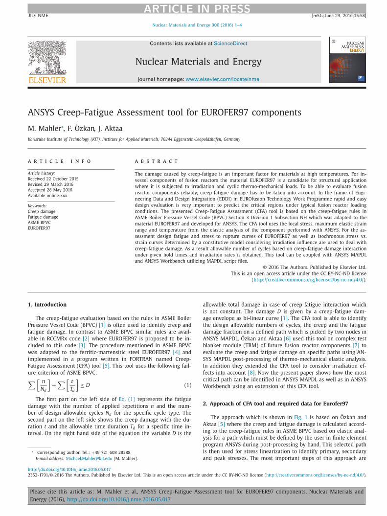
For EUROFER97 the design fatigue curves at different temper-
atures in Fig. 2 (a) by Aktaa et al. [9] are used to get information
about fatigue behavior. For a given total strain range [1]
�ε t = K v �ε mod + K �ε c with �ε mod =
K
2 �ε max S ∗
�σ(2)
mod
Please cite this article as: M. Mahler et al., ANSYS Creep-Fatigue Asse
Energy (2016), http://dx.doi.org/10.1016/j.nme.2016.05.017
he design allowable number of cycles N d can be identified. The
otal strain range in Eq. (2) is determined according to ASME BPVC
sing the values �ɛ mod , �ɛ c and �σ mod which are calculated us-
ng the Creep-Fatigue Assessment tool. Considering only the elastic
train range �ɛ max from finite element analysis instead of the to-
al strain range �ɛ t is underestimating the creep-fatigue damage.
ue to the lack of available isochronous stress vs. strain curves for
UROFER97 in ASME code a constitutive model for RAFM steels by
ktaa and Schmitt [10] considering irradiation effects [11] is used
o calculate required stress and strain values for consideration of
old time effects. For the creep behavior stress to rupture curves
t different tem peratures in Fig. 2 (b) by Tavassoli [12] on EURO-
ER97 are used to get the minimum time to rupture T d of a given
reep stress which is based on the total strain range identified be-
ore and the use of the constitutive model for RAFM steels by Ak-
aa and Schmitt [ 10 , 11 ] in terms of isochronous stress vs. strain
urves.
Fig. 2 (c) shows examples of isochronous stress vs. strain curves
n EUROFER97 at 450 °C. These curves are predicted using the con-
titutive model [ 10 , 11 ] and show the influence of irradiation and
old time on EUROFER97. For the non-irradiated state two curves
re visible. One without hold time and one with a hold time of
0 0 0 h which results in a reduction of stresses in the stress vs.
train curve. For this hold time another curve with an irradiation
ate of 15 dpa is given. Compared to the non-irradiated curve this
urve is shifted to higher stresses due to irradiation hardening.
All details and requirements on calculation of creep and fatigue
amage are explained in ASME BPVC Section 3 Division 1 Subsec-
ion NH including a lot of steps to be taken into account. Due to
he huge number of steps to be followed in ASME code and in
ome cases due to lack of available material data for EUROFER97
he Creep-Fatigue Assessment tool was initially developed [5] . At
his development stage the main disadvantage of this tool was that
he path for Creep-Fatigue Assessment must be selected by hand in
NSYS post-processing.
Now in the present paper the approach is extended to be able
o automatically identify the most critical path. With this extension
he disadvantage of selecting a specific path within a component
y the user itself can be avoided. Therefore a region of interest
as to be defined in ANSYS MAPL or Workbench post-processing,
espectively. The general idea is shown with the green boxes in
ig. 1 . One region must be on the inner and one on the outer sur-
ace of the component. Based on this selection the attached nodes
re extracted to create paths for stress linearization and to identify
he elastic strain range based on the thermal and the two struc-
ural analyses for primary and primary + secondary loads.
ssment tool for EUROFER97 components, Nuclear Materials and
M. Mahler et al. / Nuclear Materials and Energy 0 0 0 (2016) 1–4 3
ARTICLE IN PRESS
JID: NME [m5G; June 24, 2016;15:58 ]
Fig. 2. Design fatigue curves [9] (a), stress to rupture curves [12] (b) and isochronous stress vs. strain curves [5] including hold time and irradiation effects (c).
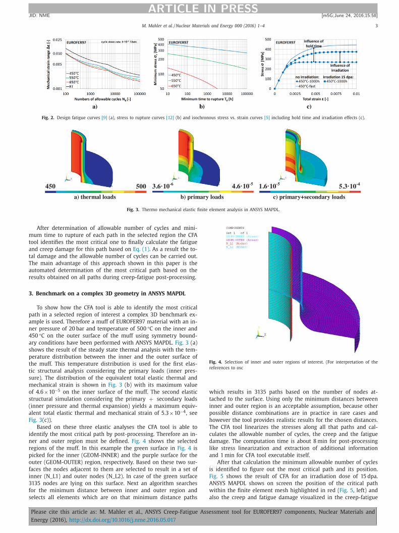
a) thermal loads b) primary loads c) primary+secondary loads
450 500 3.6·10-6 4.6·10-5 1.6·10-5 5.3·10-4
Fig. 3. Thermo mechanical elastic finite element analysis in ANSYS MAPDL.
m
t
a
t
T
a
r
3
p
a
n
4
a
s
p
t
t
s
m
o
s
(
a
F
i
n
r
p
o
f
i
3
f
s
Fig. 4. Selection of inner and outer regions of interest. (For interpretation of the
references to osc
w
t
i
p
h
T
c
d
l
a
i
F
A
w
a
After determination of allowable number of cycles and mini-
um time to rupture of each path in the selected region the CFA
ool identifies the most critical one to finally calculate the fatigue
nd creep damage for this path based on Eq. (1) . As a result the to-
al damage and the allowable number of cycles can be carried out.
he main advantage of this approach shown in this paper is the
utomated determination of the most critical path based on the
esults obtained on all paths during creep-fatigue post-processing.
. Benchmark on a complex 3D geometry in ANSYS MAPDL
To show how the CFA tool is able to identify the most critical
ath in a selected region of interest a complex 3D benchmark ex-
mple is used. Therefore a muff of EUROFER97 material with an in-
er pressure of 20 bar and temperature of 500 °C on the inner and
50 °C on the outer surface of the muff using symmetry bound-
ry conditions have been performed with ANSYS MAPDL. Fig. 3 (a)
hows the result of the steady state thermal analysis with the tem-
erature distribution between the inner and the outer surface of
he muff. This temperature distribution is used for the first elas-
ic structural analysis considering the primary loads (inner pres-
ure). The distribution of the equivalent total elastic thermal and
echanical strain is shown in Fig. 3 (b) with its maximum value
f 4.6 ×10 −5 on the inner surface of the muff. The second elastic
tructural simulation considering the primary + secondary loads
inner pressure and thermal expansion) yields a maximum equiv-
lent total elastic thermal and mechanical strain of 5.3 ×10 −4 , see
ig. 3 (c)).
Based on these three elastic analyses the CFA tool is able to
dentify the most critical path by post-processing. Therefore an in-
er and outer region must be defined. Fig. 4 shows the selected
egions of the muff. In this example the green surface in Fig. 4 is
icked for the inner (GEOM-INNER) and the purple surface for the
uter (GEOM-OUTER) region, respectively. Based on these two sur-
aces the nodes adjacent to them are selected to result in a set of
nner (N_L1) and outer nodes (N_L2). In case of the green surface
135 nodes are lying on this surface. Next an algorithm searches
or the minimum distance between inner and outer region and
elects all elements which are on that minimum distance paths
Please cite this article as: M. Mahler et al., ANSYS Creep-Fatigue Asse
Energy (2016), http://dx.doi.org/10.1016/j.nme.2016.05.017
hich results in 3135 paths based on the number of nodes at-
ached to the surface. Using only the minimum distances between
nner and outer region is an acceptable assumption, because other
ossible distance combinations are in practice in rare cases and
owever the tool provides realistic results for the chosen distances.
he CFA tool linearizes the stresses along all that paths and cal-
ulates the allowable number of cycles, the creep and the fatigue
amage. The computation time is about 8 min for post-processing
ike stress linearization and extraction of additional information
nd 1 min for CFA tool executable itself.
After that calculation the minimum allowable number of cycles
s identified to figure out the most critical path and its position.
ig. 5 shows the result of CFA for an irradiation dose of 15 dpa.
NSYS MAPDL shows on screen the position of the critical path
ithin the finite element mesh highlighted in red ( Fig. 5 , left) and
lso the creep and fatigue damage visualized in the creep-fatigue
ssment tool for EUROFER97 components, Nuclear Materials and

4 M. Mahler et al. / Nuclear Materials and Energy 0 0 0 (2016) 1–4
ARTICLE IN PRESS
JID: NME [m5G; June 24, 2016;15:58 ]
Table 1
CFA results for different hold times and irradiation rate of 15 dpa.
Hold time (h) Allowable cycles (–) Fatigue damage (–) Creep damage (–)
0 > 10 0 0 0 0 1 0
1 65418 0 .065 0 .411
100 2370 0 .002 0 .979
10 0 0 323 0 .0 0 0 0 .997
Fig. 5. CFA results for 15 dpa. (For interpretation of the references to osc
A
E
r
a
d
R
damage interaction diagram ( Fig. 5 , right). A prompt on screen
shows in addition the maximum allowable number of cycles for
this critical path which is equal to 65,418 cycles under 1 h hold
time. The results of other hold times at same irradiation rate are
listed in Table 1.
Due to the used shape of interaction diagram for calculation of
creep and fatigue damage it is clearly visible that an increase in
hold time reduces the fatigue and increases the creep damage. As
a result the allowable numbers of cycles decrease with increasing
hold time on the most critical path. The main advantage of this
tool extension is that the user does not have to select the critical
region by hand. As it is well known due to creep not the region of
maximum stress must be the critical one. In some cases the region
of maximum temperature is critical.
4. Conclusion
Based on the results the following conclusions can be deducted:
• A powerful Creep-Fatigue Assessment tool for EUROFER97 was
developed as post-processing for ANSYS MAPDL and also avail-
able for ANSYS Workbench.
Please cite this article as: M. Mahler et al., ANSYS Creep-Fatigue Asse
Energy (2016), http://dx.doi.org/10.1016/j.nme.2016.05.017
• Preliminary thermo-mechanical elastic analysis for stress lin-
earization is based on three finite element analysis: → thermal,
primary and primary + secondary loads. • CFA tool can be used for any complex 3D structures. • Automated identification of the most critical path in the com-
ponent by selecting areas of interest is realized. • CFA results for different hold times have been presented for an
irradiation rate of 15 dpa. • Application to real structures and further developments of re-
sulting needs for optimization are ongoing.
cknowledgments
This work has been carried out within the framework of the
UROfusion Consortium and has received funding from the Eu-
atom research and training programme 2014-2018 under grant
greement no. 633053 . The views and opinions expressed herein
o not necessarily reflect those of the European Commission.
eferences
[1] ASME, Boiler Presssure and Vessel Code, Section III, Division 1, Subsection NH,
Appendix T, 2004.
[2] Afcen, RCCMRx Code 2012, 2012. [3] F. Tavassoli , Eurofer steel, development to full code qualification, Procedia Eng.
55 (2013) 300–308 . [4] R. Lindau , A. Möslang , M. Schirra , Thermal and mechanical behaviour of re-
duced-activation ferritic-martensitic steel EUROFER, Fusion Eng. Design 61–62(2002) 659–664 .
[5] F. Özkan , J. Aktaa , Creep fatigue assessment for EUROFER components, Fusion
Eng. Des. 100 (2015) 536–540 . [6] F. Özkan , J. Aktaa , Creep-fatigue design rules for EUROFER97, ICFRM-16 Poster
ID 16-170 Beijing, China, 2013 . [7] F. Cismondi , S. Kecskes , G. Aiello , HCPB TBM thermo mechanical design: as-
sessment with respect codes and standards and DEMO relevancy, Fusion Eng.Des. 86 (2011) 2228–2232 .
[8] F. Özkan , J. Aktaa , Creep fatigue assessment macro in MAPDL for EUROFER,
SOFT-2014 Poster ID P2.124 San Sebastian, Spain, 2014 . [9] J. Aktaa , M. Weick , M. Walter , High Temperature Creep-Fatigue Structural
Design Criteria for Fusion Components Built from EUROFER 97, FZKA 7309Forschungszentrum Karlsruhe (2007) .
[10] J. Aktaa , R. Schmitt , High temperature deformation and damage behavior ofRAFM steels under low cycle fatigue loading: experiments and modeling, Fu-
sion Eng. Des. 81 (2006) 2221–2231 .
[11] J. Aktaa , C. Petersen , Modeling the constitutive behavior of RAFM steels underirradiation conditions, J. Nuclear Mater. 417 (2011) 1123–1126 .
[12] F. Tavassoli , Fusion Demo Interim Structural Design Criteria (DISDC) TechnicalReport TW4-TTMS-005-D01, CEA, 2004 .
ssment tool for EUROFER97 components, Nuclear Materials and