requirements for pressure vessels fabrication...asme bpvc sec. viii - rules for constructions of...
TRANSCRIPT
TECHNICAL SPECIFICATION No. I-ET-3010.00-1200-540-P4X-002
CLIENT: SRGE
SHEET 1 of 34
PROJECT: - -
UNIT: -
DP&T-SRGE
TITLE:
REQUIREMENTS FOR PRESSURE VESSELS FABRICATION NP-1
ESUP
MICROSOFT WORD / V.2016 / I-ET-3010.00-1200-540-P4X-002_A
I N D E X O F R E V I S I O N S
R E V . D E S C R I P T I O N A N D / O R R E V I S E D S H E E T S
0 ORIGINAL ISSUE
A ITEMS 1; 2.1; 2.2; 2.3; 2.4; 3.2; 4.1.3; 5; 5.3; 6.1.9; 7.13; 8.2.13 and 8.2.23 REVIEWED. ITEM 2 ADDED.
REV. 0 REV. A REV. B REV. C REV. D REV. E REV. F REV. G REV. H
DATE AUG/27/18 MAY/17/19
DESIGN EEA/EBET ESUP
EXECUTION ESTEVES PONTE
CHECK PONTE DANISCHMIDT
APPROVAL JUVENTINO JUVENTINO
THE INFORMATION CONTAINED IN THIS DOCUMENT IS PETROBRAS PROPERTY AND MAY NOT BE USED FOR PURPOSES OTHER THAN THOSE SPECIFICALLY INDICATED HEREIN
THIS FORM IS PART OF PETROBRAS N-381 REV. L
PRELIMIN
ARY
TECHNICAL SPECIFICATION No .
I-ET-3010.00-1200-540-P4X-002 REV:
A
UNIT - SHEET:
2 of 34 TITLE: REQUIREMENTS FOR PRESSURE VESSELS
FABRICATION
NP-1
ESUP
SUMMARY
1 SCOPE ....................................................................................................................... 3
2 NORMATIVE REFERENCES ..................................................................................... 3
3 DEFINITIONS AND ABBREVIATIONS ...................................................................... 4
4 GENERAL CONDITIONS ........................................................................................... 6
5 NON-DESTRUCTIVE TESTING ................................................................................. 9
6 MATERIALS ............................................................................................................. 10
7 FABRICATION ......................................................................................................... 11
8 FABRICATION INSPECTION .................................................................................. 19
9 HYDROSTATIC TEST .............................................................................................. 22
10 ANNEX A – FIGURES .............................................................................................. 26
PRELIMIN
ARY
TECHNICAL SPECIFICATION No .
I-ET-3010.00-1200-540-P4X-002 REV:
A
UNIT - SHEET:
3 of 34 TITLE: REQUIREMENTS FOR PRESSURE VESSELS
FABRICATION
NP-1
ESUP
1 SCOPE
This Technical Specification establishes requirements for the fabrication of Pressure Vessels used in PETROBRAS offshore facilities. Pressure vessel is understood to mean the equipment defined in I-ET-3010.00-1200-540-P4X-001 – REQUIREMENTS FOR PRESSURE VESSELS DESIGN - such as vessels, filters, towers, and heat exchangers. This technical Specification is based on ASME BPVC Section VIII and establishes complementary requirements to be complied with when fabricating for PETROBRAS. Codes others than ASME BPVC Section VIII may be used but shall be submitted for PETROBRAS approval and this Technical Specification shall be used only when applicable.
2 NORMATIVE REFERENCES
The pressure vessels fabricated in accordance with this technical specification must follow, where applicable, the following documents:
2.1 CLASSIFICATION SOCIETY
MANUFACTURER shall perform the work in accordance with the requirements of Classification Society.
MANUFACTURER is responsible for submitting to the Classification Society all documentation in compliance with stated Rules.
2.2 CODES AND STANDARDS
The following codes and standards include provisions for this specification. The latest issue of the references shall be used unless otherwise agreed. Other recognized standards may be used, provided it can be shown that they meet or exceed the requirements of the standards referenced below:
API RP 945 - Avoiding Environmental Cracking in Amine Units
API RP 578 - Guidelines for a Material Verification Program (MVP) for New and
Existing Assets
ASME BPVC Sec. VIII - Rules for Constructions of Pressure Vessels
ASME BPVC Sec.V - Nondestructive Examination
ASME PCC-1 - Guidelines for Pressure Boundary Bolted Flange Joint Assembly
ASTM A435 - Standard Specification for Straight-Beam Ultrasonic Examination of
Steel Plates
ASTM A578 - Straight-Beam Ultrasonic Examination
ASTM E10 - Standard Test Method for Brinell Hardness of Metallic Materials
ASTM E92 - Standard Test Method for Vickers Hardness of Metallic Materials
PRELIMIN
ARY
TECHNICAL SPECIFICATION No .
I-ET-3010.00-1200-540-P4X-002 REV:
A
UNIT - SHEET:
4 of 34 TITLE: REQUIREMENTS FOR PRESSURE VESSELS
FABRICATION
NP-1
ESUP
ASTM E165 - Standard Test Method for Liquid Penetrant Examination
ASTM E384 - Standard Test Method for Microindentation Hardness of Materials
ASTM E709 - Standard Guide for Magnetic Particle Examination
ASTM E1032 - Standard Test Method for Radiographic Examination of Weldments
ASTM E1444 - Standard Practice for Magnetic Particle Examination
AWS D1.1 - Structural Welding Code – Steel
ISO 8501-1 - Preparation of Steel Substrates before Application of Paints and
Related Products
ISO 151546 - Petroleum and Natural Gas Industries - Materials for Use in H2S
Containing Environments in Oil and Gas Production
TEMA - Standards of the Tubular Exchanger Manufacturers Association
2.3 GOVERNMENTAL REGULATION
NR - 10 - Ministério do Trabalho e Emprego (Brazilian Labor Ministry) – Norma
Regulamentadora N° 10 (NR-10) – “SEGURANÇA EM INSTALAÇÕES E SERVIÇOS EM ELETRICIDADE”.
NR - 13 - Ministério do Trabalho e Emprego (Brazilian Labor Ministry) – Norma
Regulamentadora N° 13 (NR-13) - "CALDEIRAS, VASOS DE PRESSÃO, TUBULAÇÕES E TANQUES METÁLICOS DE ARMAZENAMENTO"
Brazilian Government regulations are mandatory and shall prevail, if more stringent, over the requirements of this specification and other references herein.
2.4 REFERENCE DOCUMENTS
I-ET-3010.00-1200-540-P4X-001 - REQUIREMENTS FOR PRESSURE VESSELS
DESIGN
I-ET-3010.00-1200-955-P4X-001 - WELDING
I-ET-3010.00-1200-956-P4X-002 - GENERAL PAINTING
2.5 CONFLICTING REQUIREMENTS
In any case of conflicts or ambiguities related this specification and other cited document (Classification Society rules, Governmental regulations, referenced codes, rules, standards and other PETROBRAS document), MANUFACTURER shall revert to PETROBRAS for clarification prior to start fabrication activities.
3 DEFINITIONS AND ABBREVIATIONS
3.1 DEFINITIONS
PACKAGER: Company or organization responsible for the design, erection and test of the package where the pressure vessel under consideration is located.
MANUFACTURER: Company or organization responsible for the complete or partial fabrication of the vessel, in those cases in which fabrication is completed at the job site.
PRELIMIN
ARY
TECHNICAL SPECIFICATION No .
I-ET-3010.00-1200-540-P4X-002 REV:
A
UNIT - SHEET:
5 of 34 TITLE: REQUIREMENTS FOR PRESSURE VESSELS
FABRICATION
NP-1
ESUP
Should the mechanical design and fabrication of the vessel be done by different organizations, the term MANUFACTURER shall apply to both entities.
PURCHASER: The Company designated as such in the contract or the purchase order.
MAP OF REPAIRED DEFECTS: Register indicating all welded repairs in plates. This register shall allow the precise location of repaired areas in the equipment.
CLAD STEELS: Steels produced by hot roll cladding, explosive welding, surfacing by welding, or combined weld/hot roll cladding.
SCREENING TEST: Sample receiving test performed in welding consumables
CLASS A EQUIPMENT: Equipment subjected to all applicable requirements from this Technical Specification
CLASS B EQUIPMENT: Pressure vessels that accomplishes with all the following characteristics:
Service fluid: hydrocarbon with flashpoint over 60 ºC at ambient temperature and design pressure between 103 and 196 kPa, non-contaminated water, compressed air or non-flammable fluid;
Equipment with no service restriction, such as Service with H2S;
No impact test requirement;
Material: carbon steel with no internal clad;
Design code: ASME BPVC Section VIII Division 1;
Neither fully radiographic examination nor PWHT are a code requirement.
3.2 ABBREVIATIONS
HAZ - Heat Affected Zone
ITP - Inspection and Test Plan
MT - Magnetic Particle Examination
NDE - Non-Destructive Examination
PMI - Positive Material Identification
PT - Liquid Penetrant Examination
PWHT - Postweld Heat Treatment
UT - Ultrasonic Examination
RT - Radiographic Examination
WEII - Welding Execution and Inspection Instructions
WPQR - Welding Procedure Qualification records
WPS - Welding procedure specification
PRELIMIN
ARY
TECHNICAL SPECIFICATION No .
I-ET-3010.00-1200-540-P4X-002 REV:
A
UNIT - SHEET:
6 of 34 TITLE: REQUIREMENTS FOR PRESSURE VESSELS
FABRICATION
NP-1
ESUP
4 GENERAL CONDITIONS
4.1 MANUFACTURER´S RESPONSIBILITIES
Fabrication shall be conform to the requirements in the Material Requisition and requirements in the contract, and it shall be done in accordance with the approved fabrication drawings. Any omissions or mistakes found by the MANUFACTURER in any of the documents provided by PETROBRAS (or PURCHASER) shall be referred to PETROBRAS (or PURCHASER) for a proper solution, so that the MANUFACTURER remains full responsible for the fabrication of the equipment.
All documents required by NR-13 shall be included in fabrication documents.
Personnel and procedure qualification for welding and for NDT shall be in accordance with latest revision of I-ET-3010.00-1200-900-P4X-001 – Personnel and procedure qualification.
4.2 FABRICATION DOCUMENTS
Fabrication documents that shall be submitted to PETROBRAS includes, at least (when applicable):
Inspection and Tests Plan (*see NOTE 1);
Technical specifications of materials and consumables;
Traceability Report, including marking transfer procedures complying with paragraph UG-77 of ASME BPVC Section VIII Division 1;
WPS, WPQR, WEII, welding plans;
Screening test procedure for welding consumables;
Production tests plan;
NDE procedures;
PMI procedure;
Flange assembly procedure;
Tube to Tubesheet Expanding procedure;
Procedure for ferrite content examination;
Hardness test procedure;
Procedure for applying thermal insulation;
Internal organic coating procedure (as applicable);
External coating procedure (painting, etc.);
Internal clad procedure;
Refractory procedure;
Repair procedure, including defect removing method and examinations after repairing;
Dimensional examination protocol, including tolerances;
PWHT procedure;
PRELIMIN
ARY
TECHNICAL SPECIFICATION No .
I-ET-3010.00-1200-540-P4X-002 REV:
A
UNIT - SHEET:
7 of 34 TITLE: REQUIREMENTS FOR PRESSURE VESSELS
FABRICATION
NP-1
ESUP
Hydrostatic Pressure Test procedure;
Pneumatic Pressure Test procedure;
Helium Pressure Test procedure (as applicable);
Clean-up and drying procedures for the vessel after the hydrostatic test;
Pickling, passivation and inertization procedures;
Preservation procedure (as a minimum for 6 months);
Transportation and Store procedure;
*NOTE 1: The ITP shall have at least:
identification of stages throughout the entire fabrication cycle of equipment, when checks or inspections are performed by the manufacturer and by the client, including those performed in sub-suppliers. It shall identify the types of examinations, tests or checks to be done;
care taken with temporary welds, including method to be used for their removal and future inspection;
indication of qualification/certification of personnel performing the activities of inspection, check and special production processes;
indication of procedures and acceptability standards for all quality characteristics and requirements, including the subjective ones and of sub-supplies;
identification and preparation of quality records, mentioning its various types of records;
indication of devices/equipment, including the required accuracy, in order to obtain quality when checking critical dimensions, operation and performance tests;
4.3 PRESENTATION OF TECHNICAL DOCUMENTS
Documents listed in 4.2 as well as the documents specified below shall be submitted to the inspector for examination before the beginning of the corresponding activity:
Fabrication drawings approved for execution;
Material quality certificates;
Certificates of consumable material quality;
WPQR´s;
Welders/Weld operators qualification records;
Report indicating procedures and inspectors and/or qualified non-destructive testing operators and qualified welding inspectors;
Report of welding record.
4.4 TECHNICAL FABRICATION DATA BOOK
MANUFACTURER shall furnish a complete set of technical fabrication data books for each equipment containing at least the following documents:
Certified mechanical design and fabrication drawings and documents;
PRELIMIN
ARY
TECHNICAL SPECIFICATION No .
I-ET-3010.00-1200-540-P4X-002 REV:
A
UNIT - SHEET:
8 of 34 TITLE: REQUIREMENTS FOR PRESSURE VESSELS
FABRICATION
NP-1
ESUP
Technical specifications;
Data sheets;
Material quality certificates of pressure parts, internals and equipment supporting parts;
Quality certificates of welding consumables, including drying control;
Traceability map of materials and welding consumables;
Report with NDE´s results;
Drawing with radiography spot positions;
Map of repaired defects;
PMI report;
Production test reports;
Report of dimensional inspection, including dimensions measured;
PWHT report, including temperature chart;
Pressure test report;
Pneumatic test report;
Hardness test report;
Hydrostatic test report, including pressure chart;
Report of ferrite content examination;
Report of internal coating/clad inspection;
Report of external coating inspection;
Report of insulation inspection;
Report of nonconformities, if any;
Hibernation procedure;
Assembly procedure.
Data files (soft copies) of recordable NDE´s;
All documents required by NR-13.
4.5 FILES
MANUFACTURER shall keep the information required below in an organized file, making it available for PETROBRAS examination (or its authorized representative) at any time within a period of 5 years from the equipment shipping date:
A. Mill certificates for shell components: the certificate shall contain a specification to which the material conforms, the heat number, the treatment undergone by the material and the results of the chemical analysis and mechanical tests.
B. Certificates of compliance for materials obtained from sub-suppliers and for which mill certificates are unavailable: when it is not possible to prove the material specification, the manufacturer shall carry out tests and analyses and issue certificates of compliance.
PRELIMIN
ARY
TECHNICAL SPECIFICATION No .
I-ET-3010.00-1200-540-P4X-002 REV:
A
UNIT - SHEET:
9 of 34 TITLE: REQUIREMENTS FOR PRESSURE VESSELS
FABRICATION
NP-1
ESUP
C. For piping accessories and flanges manufactured in accordance with an approved standard, certificates are not required, provided they are marked as required by code ASME BPVC Section VIII. Certificates are required when markings are removed.
D. Registers of qualified welding procedures, registers of qualification of welders and weld operators.
E. Radiographic films and UT digital records, when is required.
F. Non-destructive test certificates.
G. Charts and/or certificates of hydrostatic and pneumatic tests and other tests.
H. Temperature recording charts and other heat treatment registers.
5 NON-DESTRUCTIVE TESTING
UT, MT, PT and RT shall follow requirements established at Non-Destructive Testing Technical Specification applied for the project.
5.1 VISUAL INSPECTION
It shall be performed in accordance with recognized standard previously approved by PETROBRAS.
5.2 DIMENSIONAL INSPECTION
It shall be performed in accordance with code ASME BPVC Section VIII and tolerances of Figure A 1.
5.3 POSITIVE MATERIAL IDENTIFICATION
It shall be carried out in accordance with API 578 and at Non-Destructive Testing Technical Specification applied for the project.
5.4 TIGHTNESS TEST
Bubble formation test with positive pressure performed in accordance with ASME Section V Article 10. No leak is allowed.
5.5 HARDNESS TEST
In welding procedure qualification and in production testing, the hardness measurement shall be performed with bench instrument, according to ASTM E384.
When measuring hardness in equipment, the suitability of the portable instrument shall be showed by comparison settlement in hardness measurements obtained by the portable instrument and those obtained by the bench instrument. The comparison results shall be previously submitted to PETROBRAS for approval.
The demonstration shall be performed in a welded joint of material of same applicable specification (ASTM, ASME) of equipment material to be tested, using the outline of hardness measurements for bevel similar to the equipment. Measurements performed with bench instrument, Vickers method, as per ASTM E 384, hardness HV 5 or HV 10, shall be similar to
PRELIMIN
ARY
TECHNICAL SPECIFICATION No .
I-ET-3010.00-1200-540-P4X-002 REV:
A
UNIT - SHEET:
10 of 34 TITLE: REQUIREMENTS FOR PRESSURE VESSELS
FABRICATION
NP-1
ESUP
those obtained in adjacent positions with portable instrument, being considered the maximum range of +10 % as acceptable. For equipment which may be subjected to corrosion under stress condition, the maximum range shall be +5 %. Negative ranges are not acceptable.
The comparison of measurements performed in standard blocks to decide for suitability of portable instrument device for hardness measurement is not allowed.
To measure the hardness in Heat Affected Zone (HAZ), ultrasonic-type portable instruments shall be used. For this measurement, it is required to perform the chemical attack of the joint so that the HAZ region is revealed.
Portable instruments based on Leeb (rebound) method and Poldi or elebrineller-type portable instruments shall not be used.
6 MATERIALS
6.1 GENERAL REQUIREMENTS
Material supply shall be as specified in the Material Requisition.
In those cases where basic drawings or mechanical design of the vessel are furnished by PURCHASER, the manufacturer shall use the materials indicated on those documents. The use of any alternative material presented during or after the proposal shall only be applied after it has been approved by PURCHASER.
For pressure parts (including parts welded to those) and supporting parts made of plates and pipes (example: skirt and columns), materials certificates shall be checked to verify compliance with their respective specifications.
The materials used shall be perfectly identified according to the fabrication drawing of the equipment and to the material certificate, using the criteria of code ASME Section VIII.
Pressure components shall undergo the PMI examination when they are received, except for carbon steel material. Inspection in 100 % of lot. Non-complying parts shall be identified and disposed.
Fixing elements (studs/bolts and nuts) shall undergo the PMI examination, by sampling in 20 % of its lot at the receiving, except for carbon steel materials. Sampling acceptance criteria: 100 %. In case of non-compliance, the sampling shall be extended to 100 %. Non-complying parts shall be identified and disposed.
Heat-treated fixing elements (studs/bolts and nuts) shall undergo the hardness test, by sampling in 20 % of the lot when it is received. Sampling acceptance criteria: 100 %. In case of noncompliance, the sampling shall be extended to 100 %. Non-complying parts shall be identified and disposed.
Equipment internals shall undergo the PMI examination when they are received, sampling inspection in 20 % of the lot when it is received, except for carbon steel material. In case of noncompliance, the sampling shall be extended to 100 %. Non-complying parts shall be identified and disposed.
PRELIMIN
ARY

TECHNICAL SPECIFICATION No .
I-ET-3010.00-1200-540-P4X-002 REV:
A
UNIT - SHEET:
11 of 34 TITLE: REQUIREMENTS FOR PRESSURE VESSELS
FABRICATION
NP-1
ESUP
A visual inspection shall be performed in all materials, sections and equipment used, which shall be free of:
defects which cause a sudden transition on the surface of the part;
defects which reduce the thickness of the part to a value lower than that mentioned in item 6.1.11;
any degree of corrosion for stainless steels and nonferrous metals.
corrosion above grade C of standard ISO 8501-1 for the following materials:
- Carbon Steels; - Molybdenum Alloy Steels; - Chromium Molybdenum Alloy Steels;
A map of the defects repaired on plates shall be prepared.
The thickness of all manufactured sections shall be checked. Special attention is drawn to regions of higher strain, such as the toroidal region of torispherical heads. The measured thickness shall have the thickness defined in fabrication drawing or above.
Flange faces shall be visually checked, for verification of the condition and type of grooves, being unacceptable corrosion or dents at the sealing surface.
6.2 CLAD PLATES
The surface of clad plates shall be visually checked for any signs of pitting and other types of corrosion, thickness reduction, cracks, pores and contamination, and the surface of clad plates shall be free of these defects.
The clad thickness of stainless steels in general shall be measured on the plate edge at 4 points using a copper sulfate solution attack. The measured thicknesses of the cladding shall comply with the provisions in item 6.1.11.
For equipment Class A, perform UT in the cladded plates for checking clad adherence before forming (as by standard ASTM A435). Perform this inspection, after forming, only in parts of greater grade of deformation. For Class B equipment, perform this inspection only before the forming.
7 FABRICATION
The pressure vessel’s fabrication must be in accordance with ASME Code Section VIII, with AWS Standards and the additional requirements, as follows.
7.1 FABRICATION DESIGN
If the equipment is not delivered in the assembled condition, the sections that are manufactured at the shop shall be as large as possible for transportation and shall be planned so as to minimize field fabrication and welding.
The opening for nozzles in shells and heads and the welding of components and accessories such as supporting lugs, rings, couplings, nozzle reinforcements, stiffening rings, supports for insulation and internals, both on
PRELIMIN
ARY
TECHNICAL SPECIFICATION No .
I-ET-3010.00-1200-540-P4X-002 REV:
A
UNIT - SHEET:
12 of 34 TITLE: REQUIREMENTS FOR PRESSURE VESSELS
FABRICATION
NP-1
ESUP
the internal and external parts, located less than 150 mm from field welds, shall be done in accordance with the following criteria:
a) if the equipment is delivered in the assembled condition, all accessories indicated are to be welded at the factory;
b) if the equipment is delivered in parts or sections, and if heat treatment is not foreseen, accessories shall be welded in the field;
c) if the equipment is delivered in parts or sections and if heat treatment is foreseen, accessories shall be welded at the factory and be pre-assembled at the factory, whenever possible. )
Note: All parts to be welded in the field shall be furnished after they have been duly prepared, cut out in the correct dimensions and with bevels duly finished.
7.2 AUXILIARY ASSEMBLY DEVICES
Auxiliary assembly devices shall comply with I-ET-3010.00-1200-955-P4X-001 - WELDING.
Rigid devices spaced less than 500 mm from each other shall not be used.
7.3 BEVELS
Bevels shall be dimensionally and visually checked for cleanliness and absence of the following defects:
lamellar de-cohesion;
pores;
cutting irregularities;
dents;
cracks;
discontinuities crosswise to the surface;
discontinuities parallel to the surface, over 25 mm in length.
Note: Paragraphs E., F. and G. shall be verified by non-destructive tests, when there is suspicion of those defects existence.
The visual test shall be completed by the liquid penetrant or magnetic particle test, in the following cases:
bevel thickness over 38 mm;
bevels of openings for nozzles having a nominal diameter equal to or greater than 76 mm (3”);
bevels recovered by welding;
all bevels except for carbon steel equipment without impact testing requirement.
Note: The same defects mentioned in item 7.3.1 are deemed to be unacceptable.
7.4 REPAIR OF DEFECTS FOUND IN MATERIALS
Welding repairs shall be done in accordance with item 7.6 and examined in accordance with chapter 8.
PRELIMIN
ARY
TECHNICAL SPECIFICATION No .
I-ET-3010.00-1200-540-P4X-002 REV:
A
UNIT - SHEET:
13 of 34 TITLE: REQUIREMENTS FOR PRESSURE VESSELS
FABRICATION
NP-1
ESUP
7.5 ADJUSTMENT
Sections or plates of equipment shall be adjusted within the following tolerances:
joint opening: ± 1.5 mm in relation to the design dimension;
misalignment: code ASME BPVC Section VIII, Division 1 or Division 2;
out-of-roundness along the sections, on the upper and bottom edges and on the supporting region of the skirt, see Figure A 1, reference 19.
perimeter on the upper and bottom edges of each section, see Figure A 1, reference 20;
levelling of upper and bottom edges, measured by the difference between the maximum and minimum points of each edge:
- 3 mm if the circular arc between the maximum and minimum points is equal to or smaller than 3 000 mm;
- 4 mm if the same arc is greater than 3 000 mm;
curvature: see code ASME Section VIII, being applicable only to:
- equipment subject to external pressure; - heads; - rolled plates;
total height or of sections or plates: see Figure A 1, reference 9;
verticality (plumb line): see Figure A 1, reference 1;
angular deformation: see Figure A 1, reference 31;
separation between longitudinal joints: ±10 mm in relation to the design dimensions;
distance between tangent lines: see Figure A 1, references 2;
distance between skirt ring and bottom tangent line: see Figure A 1, references 22 ;
maximum clearance between shell and skirt: see Figure A 1, reference 21.
It shall be made a pre-assembly, in the factory, of internal and external accessories of the pressure vessel (trays, cyclones, platforms and others). The scope and detailment of pre-assembly shall be agreed between the manufacturer and PETROBRAS, considering the particularities of each equipment.
7.6 WELDING
Welding shall be performed in accordance with the requirements stated in this document and with the requirements stated in the latest revision of I-ET-3010.00-1200-955-P4X-001 - WELDING.
The pre-heating, interpass heating, and post-heating methods allowed are gas burners, electric resistance or by induction, and single-flare burners shall not be allowed. It shall be preferred the use of electric resistance or induction. It shall be made a rigid control in the operation of pre-heating, interpass temperature and post-heating.
For low temperature vessels, production test shall be carried out in accordance with code ASME BPVC Section VIII.
PRELIMIN
ARY
TECHNICAL SPECIFICATION No .
I-ET-3010.00-1200-540-P4X-002 REV:
A
UNIT - SHEET:
14 of 34 TITLE: REQUIREMENTS FOR PRESSURE VESSELS
FABRICATION
NP-1
ESUP
Temporary welds, such as: welds of auxiliary assembly devices, attachment welds of thermocouples and of supports of thermal insulation (placed for heat treatment), shall be removed after performing their function. These welds shall be removed without mechanical impacts. The region of these welds shall be ground smooth to eliminate points of stress concentration, and in pressure parts shall also be examined by non-destructive tests.
Welded joints having any irregularity that may adversely affect the non-destructive test shall be ground. This requirement is mandatory for welded joints made with a straight pass to be radiographed.
When the use of assembly devices is required to keep the circularity (“bracing” type devices), it shall be observed the minimum distance of 250 mm from the circumferential joint to be welded.
The guide hole at the center of formed heads shall be closed with a reinforcing pad with the same material of the head, butt-welded and examined as required by ASME BPVC section VIII.
All welds subjected to pressure loads, in the shell and heads, shall be double- welded butt joints, full penetration and allow radiography. When the internal weld is impracticable, only the external weld may be done, adopting a method that guarantees the quality of the weld root, meeting that:
All welded joints of the shell and heads shall be designed to allow radiographic inspection, even in those cases where the design Code does not require it.
All welded joints of the shell and heads shall be, as a minimum, examined by spot radiography.
Welds of nozzles necks and manholes in the shell shall also be of the full penetration type. When this provision is impracticable due to the high thickness of the wall, the welded connection design shall be submitted to PETROBRAS for previous approval.
Temporary stiffeners should be used to avoid inward buckling of shell section during welding of nozzles 20” ND and over.
Welds between materials having different “P-numbers” shall be kept to a minimum. Whenever possible, these welds shall not be placed in contact with the fluid contained in the vessel and with the pressure wall of the vessel.
The fabrication design of the vessel shall clearly indicate the location of all welds in the shell and heads of the vessel.
Whenever possible, welds of the shell and heads shall be arranged in such a manner as not to interfere with vessel supports and nozzles, manholes and their respective reinforcements. Shell welds hidden by reinforcement plates shall be ground, examined by magnetic particles or liquid penetrant and be fully radiographed.
Welds of the shell and heads shall not interfere with internal parts welded to the vessel. For horizontal vessels, longitudinal welds of the shell on the bottom generatrix of the vessel, where they interfere with the saddle, shall not be allowed.
PRELIMIN
ARY
TECHNICAL SPECIFICATION No .
I-ET-3010.00-1200-540-P4X-002 REV:
A
UNIT - SHEET:
15 of 34 TITLE: REQUIREMENTS FOR PRESSURE VESSELS
FABRICATION
NP-1
ESUP
All welds shall be in such a position as to allow inspection without the need of dismounting the internal parts of the vessel. If this not possible, PETROBRAS approval is required.
For vertical vessels, the weld of the skirt to the vessel shell shall be located so as not to interfere with the weld of the shell to the bottom head and to allow inspection of the weld. For horizontal vessels, saddles shall also be located in such a manner as not to interfere with the circumferential welds of the vessel and allow the inspection of these welds.
For vessels less than 2000 mm in diameter, only a single longitudinal weld per joint is allowed. For diameters equal to or greater than 2000 mm, commercial length plates shall be used and smaller plates shall only be allowed for adjustment purposes.
Note: In any case the longitudinal welds of adjacent rings shall be at least 45º apart from each other.
All welds of parts externally attached to the vessel shall have a continuous weld bead. Overlapping parts in vessels operating at a temperature equal to or greater than the ambient temperature shall have a 6 mm diameter vent.
All welds of parts internally attached to the vessel shall have a 10 mm interruption at the bottom part of the weld bead.
The distance between the edges of 2 full penetration and parallel welds, in any case, shall not be less than 3 times the thickness of the thinnest plate and at least 50 mm.
The same corrosion allowance specified for the vessel shall be added to the minimum dimension of the throat of the fillet welds. Full fillet welds to which this addition is already a result of the weld geometry are an exception to this rule.
For all vessels to be postweld heat treated all welds shall be of the full penetration type, excepting for the weld of slip-on flanges and nozzles pads, where gas escape and pressure relief holes shall be provided.
Welds of lifting lugs and similar devices shall be kept at a distance at least equal to that given in item 7.6.20. If the interference is inevitable, PETROBRAS approval is required. In this case the shell weld shall be ground and examined by magnetic particles or liquid penetrant before welding of the lifting lug.
The reinforcement of welds of the equipment shall be within the limits required by ASME BPVC Section VIII
The tolerances listed in 7.5.1 shall be checked after the welding of sections and at the end of fabrication, with the equipment assembled.
For vessels with cladding any blistering detected in the visual inspection shall not be permitted.
7.7 NOZZLES
PRELIMIN
ARY
TECHNICAL SPECIFICATION No .
I-ET-3010.00-1200-540-P4X-002 REV:
A
UNIT - SHEET:
16 of 34 TITLE: REQUIREMENTS FOR PRESSURE VESSELS
FABRICATION
NP-1
ESUP
Nozzles shall be located, adjusted and welded within the tolerances presented in Figure A 1, according to the corresponding number of reference:
elevation: references 15 or 16;
deviation from nozzle axis measured in the arc: reference 32;
angular deviation from nozzle axis: reference 29;
projection: references 11 or 13;
perpendicularity of flange face in relation to the manhole or nozzle axis: references 12 and 14;
orientation of connecting flange holes with piping: references 27 and 28;
clearance between diameters for slip-on flanges: reference 10;
distance from nozzle flange face to tangent line: reference 23;
distance between centerlines of nozzles for level instruments: reference 30;
deviation between centerlines of nozzle and head: reference 26.
Welds of shell nozzles shall be examined by liquid penetrant or magnetic particle after the completion of the nozzle-to- shell weld.
Welds of the reinforcement plate shall be examined with liquid penetrant or magnetic particle.
Nozzles having a nominal diameter equal to or larger than 4” and self-reinforced nozzles with the opening in the shell having a diameter equal to eater than 100 mm shall undergo UT at the following welded joints:
full penetration welded joint between nozzle neck and vessel shell;
welded joint between nozzle neck and reinforcement plate (if any).
Note: A more restrictive provision shall be adopted if present in the standard of the specific service.
A tightness test shall be performed in the nozzle reinforcement plates to ensure complete tightness. A hole open to atmosphere is required to act as a vent.
For heat treated equipment, the tightness test shall be carried out before the heat treatment.
Holes used for the tightness test shall be filled with grease after the hydrostatic test of the vessel.
Nozzle flange faces, studs and nuts shall be protected against mechanical damage and corrosion in grooves and threads.
For jacketed equipment, the clearance provided in the design for differential expansion between the various parts shall be strictly complied with the design.
7.8 INTERNALS
PRELIMIN
ARY
TECHNICAL SPECIFICATION No .
I-ET-3010.00-1200-540-P4X-002 REV:
A
UNIT - SHEET:
17 of 34 TITLE: REQUIREMENTS FOR PRESSURE VESSELS
FABRICATION
NP-1
ESUP
Rings and other supports shall be located, adjusted and welded within the tolerances presented in Figure A 1, according to the corresponding number of reference:
supporting ring elevation: references 8 and 18;
distance between consecutive rings of tray supports: reference 6;
clearance between ring or support and shell: reference 17;
see item 8.2.18.4.
Tack welding and welding of rings and supports shall be performed in accordance with the qualified welding procedure.
When tack welding is performed, the level and elevation of tray support rings shall conform to the tolerances given in Figure A 1 references 5, 6 and 8.
After welding, the leveling of rings shall comply with the same tolerance indicated in item 7.8.3.
A liquid penetrant test shall be performed at the welded joint between the rings and supports to clad plates or when specified by the design.
Tray gaskets (and joints) shall be installed as by manufacturer recommendations.
After assembly, the dimensions and level for trays and weir plates shall be checked and registered. The maximum tolerances shall be in accordance with Figure A 1, references 3, 4 and 7.
7.9 WARPED PARTS
Repairs of warped parts due to welding, among other factors, shall be done according to a repair procedure previously approved by PETROBRAS and preferably done in the cold condition. See 8.2.22
7.10 THERMAL INSULATION AND REFRACTORY SUPPORTS AND DEVICES
Thermal insulation shall be applied after the hydrostatic test and approval of NDT’s.
7.11 HEAT TREATMENT
It shall be prepared a specific Heat Treatment procedure containing at least the following information:
type of heat treatment performed;
identification of applicable performance standard;
parameters required for performance, such as:
- beginning and ending control temperatures; - minimum and maximum heating rate; - minimum and maximum treatment temperatures; - minimum and maximum treatment times; - minimum and maximum cooling rate; - maximum difference of temperature between thermocouples;
details of support and deformation control devices of equipment;
PRELIMIN
ARY
TECHNICAL SPECIFICATION No .
I-ET-3010.00-1200-540-P4X-002 REV:
A
UNIT - SHEET:
18 of 34 TITLE: REQUIREMENTS FOR PRESSURE VESSELS
FABRICATION
NP-1
ESUP
indication of performance method, such as:
- treatment in furnace; - localized treatment;
indication of heating medium used;
furnace drawing (when applicable), indicating equipment the location inside it, burner nozzles or electrical resistances, and the overlap region when the equipment item is not fully inside the furnace;
when localized heat treatment is performed: welded joint drawing, indicating the location and distribution of electrical resistances, width of soak band (SB), width of heated band (HB), width of gradient control band (GCB) including SB, HB and insulation, distribution of thermocouples, and insulation attachment details;
type, quantity and identification (number and color in chart) of thermocouples employed;
attachment method of thermocouples to equipment;
equipment sketch and/or test coupon indicating the location and relative distance between thermocouples.
If the vessel is submitted to a post weld heat treatment (PWHT), all materials, welding consumables and procedures shall be qualified to include all predicted heat treatments during fabrication, added of one PWHT in case any additional in-site welding repair is needed. This additional heat treatment to be done by PETROBRAS, if necessary, will have the same specifications as the PWHT’s done during fabrication.
It shall be presented the charts and furnished the reports and certificates of heat treatment, including the registers of hardness measurement.
The operator of PWHT shall be qualified.
Plates, heads or other parts subject to cold or hot rolling, forming or forging, shall be heat treated as required by code ASME BPVC Section VIII.
Controlling and recording equipment shall be duly gauged and calibrated, by using the standards tracked to “Rede Brasileira de Calibração”, or similar, when the vessel is fabricated outside Brazil.
Equipment connections shall be protected against corrosion and warping.
Hardness readings shall be taken after heat treatment, being:
a hardness reading performed for each 6 m of weld;
at least two readings shall be taken per longitudinal bead and per circumferential bead. The hardness measurement in circumferential joint shall be made in all crossings with longitudinal welds;
at least one hardness reading shall be taken in the flange connection with neck and one in the nozzle connection with vessel;
at least one reading shall be taken for each WPS used;
one reading in region of removal of temporary welds.
Note: Each reading shall contain three points in weld metal (cast zone), three points in each HAZ, and one point in base metal of each side of bead.
PRELIMIN
ARY
TECHNICAL SPECIFICATION No .
I-ET-3010.00-1200-540-P4X-002 REV:
A
UNIT - SHEET:
19 of 34 TITLE: REQUIREMENTS FOR PRESSURE VESSELS
FABRICATION
NP-1
ESUP
The hardness shall be according to design code. For vessels with special services, shall be adopted the requirements of the standards about those services (e.g.: ISO15156).
For vessels in wet H2S/amine service, PWHT is required for all welded joints.
Production test plates shall be treated together with the equipment. Their localization is established at the option of the PETROBRAS inspection.
MANUFACTURER shall inform how many PWHTs the vessel can withstand due carried out repairs.
7.12 LOCALIZED HEAT TREATMENT
Localized heat treatment is only allowed in circumferential welds and with prior approval of PETROBRAS.
Localized heat treatment in welded nozzles and accessories may only be carried out with heated band circumferential to equipment, and with prior approval of PETROBRAS.
A detailed procedure shall be prepared, based on ASME BPVC Section VIII and WRC 452, specific for each weld, as per 8.1.1.
7.13 SURFACE PREPARATION AND PAINTING
Internal and external painting shall be according to I-ET-3010.00-1200-956-P4X-002 – GENERAL PAINTING.
Color code shall be in accordance with DR-ENGP-I.1.15.
Painting shall be applied over weld joints only after the hydrostatic test.
Grounding lug shall not be painted.
8 FABRICATION INSPECTION
8.1 GENERAL
Non-destructive tests required after welding shall be done at least 48 hours after the last welding is performed in pressure parts and equipment support parts.
PACKAGER/MANUFACTURER shall submit the Inspection and Test Plan (ITP) based on the technical data sheet with all witnessed inspections and tests identified. The notification period for such inspections shall be informed in advance.
PACKAGER/MANUFACTURER shall ensure that all the witnessed inspection requirements by the Classification Society are fully met and the due notice requirements are satisfied.
8.2 EXAMINATION
Welds of any parts, regardless of the material, thickness or service, shall be fully (100%) radiographed before any severe deformation (thickness to local
PRELIMIN
ARY
TECHNICAL SPECIFICATION No .
I-ET-3010.00-1200-540-P4X-002 REV:
A
UNIT - SHEET:
20 of 34 TITLE: REQUIREMENTS FOR PRESSURE VESSELS
FABRICATION
NP-1
ESUP
radius ratio greater than 5%), by any process, such as spinning, pressing and rolling. After deformation, the welds and the most deformed areas shall be examined by magnetic particles or liquid penetrant, before any manufacturing operation is subsequently carried out.
Welds used for closing guide-holes at the center of formed heads shall be fully radiographed.
For spot radiography examination, the weld crossing point shall be inspected, in order to achieve welds made by all welders and welding operators and the greatest number of positions not easily accessible.
Nondestructive tests for the welded joint shall be redone in the case of repair or alteration of joints.
For restoration of the base metal thickness by weld, the nondestructive tests specified in code ASME Section VIII shall be performed.
It shall be made a visual inspection and a liquid penetrant or magnetic particle test in surfaces under temporary welds, after they have been removed. Those surfaces shall be free of:
undercuts;
incomplete removal of weld;
unacceptable defects for welds of parts inter pressure.
Note: If there is thickness reduction, use UT for measuring the thickness. Value obtained shall comply with item 6.1.11.
When preheating is required, liquid penetrant or magnetic particle tests shall be performed in the areas where weld points have been removed and areas subject to gouging.
A magnetic particle or liquid penetrant test shall be performed before the hydrostatic test in the following regions, except for equipment Class B:
internally and externally welded joints, covering a 200 mm wide area centered at the joint;
plate repair welds;
regions of weld removed from auxiliary assembly device and temporary weld;
welds for attachment of accessories.
For equipment subject to heat treatment, the requirements in item 8.2.8 shall be met before and after the heat treatment.
Liquid penetrant test or magnetic particle test shall be performed on all vessel lifting devices (example: lifting lugs).
In heat exchangers, a liquid penetrant test shall be done in tube to tubesheet welds and in curved region of U-tubes.
After fabrication, a full dimensional inspection shall be performed, with issuance of a specific report covering all dimensions applicable to equipment, referenced in Figure A 1, including the required dimensions, the values found, and their respective tolerances.
PRELIMIN
ARY

TECHNICAL SPECIFICATION No .
I-ET-3010.00-1200-540-P4X-002 REV:
A
UNIT - SHEET:
21 of 34 TITLE: REQUIREMENTS FOR PRESSURE VESSELS
FABRICATION
NP-1
ESUP
For heat exchangers, the dimensional tolerances of TEMA are applied when there is no reference in ANNEX A – FIGURES.
All vesels delivered in the disassembled condition shall be fully or partially pre-mounted at the shop for a dimensional check. Pre-assembly shall be done with an adequate temporary attachment and shall cover the entire vessel or at least the largest possible part of the vessel.
Trays, gratings, baffles and other internal parts of the vessel that are dismountable and delivered in the disassembled condition shall also be fully pre-mounted at its installation position inside the vessel, at the manufacturer’s shop, when included within the scope of supply.
Bevels hall be dimensionally and visually checked in accordance with item 7.3.
For equpment and sections delivered in the assembled condition, a check shall be made in the skirt or supports to verify compatibility of the arrangement and dimension of holes and anchor bolts. A check shall be done to verify if the holes allow thermal expansion specified for the equipment.
The equpment and sections delivered in the assembled condition shall be examined as specified in items 8.2.18.1 to 8.2.18.4.
The osition of nozzles in relation to the requirements specified in item 7.7.1 shall be verified.
Supports of internals shall be visually checked to verify if the position and attachment details of the support are in accordance with the design specification.
Baffle plates shall be visually inspected to check if the position of the plates conforms to the design specification, allowing a ± 10 mm tolerance, in any direction.
The supports for platforms, ladders and piping systems and for reinforcement rings and thermal insulation shall be visually inspected. The following requirements for these supports shall be checked:
the location shall not interfere with other vessel elements;
they shall conform to the design, specially as regards their dimensions and fillet weld dimensions and the clearance specified in the Figure A 1, reference 17;
they shall have holes for water drainage, when necessary (if not, holes shall be drilled);
they shall have the oblong holes called for in the design for differential expansion between the various parts (if not, oblong holes shall be drilled);
if the plates continuously welded to the vessel have the hole functioning as a vent (this hole shall be left open and shall be filled with grease after the hydrostatic test).
The condition of all internal parts delivered shall be visually checked for mechanical damage and corrosion in accordance with item 6.1.9.
Beams shall be visually examined to check if the initial deflection for compensation (when specified in the design) has the specified value.
Beams and their supports shall be checked to verify if the dimensions and holes for attachment are in accordance with the design.
PRELIMIN
ARY
TECHNICAL SPECIFICATION No .
I-ET-3010.00-1200-540-P4X-002 REV:
A
UNIT - SHEET:
22 of 34 TITLE: REQUIREMENTS FOR PRESSURE VESSELS
FABRICATION
NP-1
ESUP
All internal parts shall be visually examined to check if the drain holes specified in the design are present.
After unwarping of warped parts, the higher strain regions in these parts shall be examined with penetrant liquid or magnetic particles.
9 HYDROSTATIC TEST
9.1 GENERAL
Hydrostatic test shall be performed only after presentation of all inspection and testing records provided in approved ITP.
All vessels delivered in the assembled condition shall be hydrostatically tested at the manufacturer’s shop prior to shipment. This test should be preferably performed with the vessel in the horizontal position and the test pressure values determined by the designer.
Vents shall be provided at the high points of the vessel to purge air from the tested component while it is being filled.
All gaskets used in hydrostatic testing shall comply with design specification, otherwise it shall have prior approval of PETROBRAS.
Studs used in hydrostatic test shall comply with the design specification or have resistance compatible with the calculated torque. The design torque shall be applied in the tightening sequence, according to ASME PCC-1, using a calibrated torque wrench. The record of applied torque shall be presented to inspector at the moment of testing.
9.2 TESTING
The test shall only be performed after 48 hours have elapsed from the last welding or after PWHT in pressure parts and equipment supporting parts.
9.3 WATER
The test fluid characteristics shall neither cause degradation of equipment, nor cause scaling or build-up of sediments. If there are any requirements in the design regarding water purity characteristics, these characteristics shall be controlled.
For carbon steel and low alloy equipment, in order to prevent brittle fracture during test, the water temperature shall be kept, at least, 17 ºC above the minimum metal design temperature or, at least, at 15 ºC, whichever is greater. Therefore, hydrostatic testing is prohibited with water at temperature below 15 ºC.
Note: If the water temperature is near the minimum limit, thermometers shall be installed in the lower region of the equipment.
For materials different from carbon steel and steel alloy, the test water temperature shall be established in the equipment design, regarding its properties.
PRELIMIN
ARY
TECHNICAL SPECIFICATION No .
I-ET-3010.00-1200-540-P4X-002 REV:
A
UNIT - SHEET:
23 of 34 TITLE: REQUIREMENTS FOR PRESSURE VESSELS
FABRICATION
NP-1
ESUP
The maximum chloride content permitted in the water shall be defined by the designer, but not greater than 50 ppm for equipment made of stainless steel or having an internal cladding consisting of this material.
9.4 WELDING PROHIBITED
No weld shall be done on the equipment and on any part in electric contact with the equipment while the equipment is holding water.
9.5 PRESSURE GAGES
At least two pressure gages shall be used, and a third one shall be used when the test takes more than 6 hour, observing the requirements of items 9.5.1.1 to 9.5.1.5.
At least one of the pressure gages shall be located in an area allowing easy access, visible to the inspector during the entire testing and pressurization time and one of the pressure gages shall be located at the top of the equipment.
Pressure gages shall be calibrated before the beginning of the test. Calibration certificate shall not be older than 3 months at test data. Calibration shall be done using a standard deadweight gauge or a calibrated master pressure gauge or a column of mercury.
The maximum scale value shall always be within 1.5 and 4 times the test pressure and be preferably twice the test pressure.
The smallest scale division shall not exceed 5% of the maximum scale indication.
Valves shall be provided between the pressure gages and equipment to allow substitution, if necessary.
9.6 SAFETY AND ACCESS
Safety conditions shall be provided before the test is begun.
Personnel and equipment employed for test shall be in a safe place, which means they shall be out of the space defined by the effective isolation of risk area, corresponding to, at least, the reach of pressure water jet.
Access to all parts to be inspected during the test shall be provided.
Connections of auxiliary fill piping of the vessel shall have their ratings compatible with the test pressure.
No mechanical intervention may be performed in the equipment under test while there is pressure in system, such as, for example, tightening of flanges.
9.7 SCHEME OF THE HYDROSTATIC TEST
Elevate the pressure until 50% of hydrostatic test pressure (PT) and proceed the equipment inspection.
Increase gradually, with a rise ratio of 20% of PT per minute or lower, till reach the hydrostatic test pressure. Remain in this pressure during, at least, 30 minutes.
Low down the pressure up to 77% of PT, being used a similar raise reduction the one that was used for the pressurization, and to execute new inspection.
PRELIMIN
ARY
TECHNICAL SPECIFICATION No .
I-ET-3010.00-1200-540-P4X-002 REV:
A
UNIT - SHEET:
24 of 34 TITLE: REQUIREMENTS FOR PRESSURE VESSELS
FABRICATION
NP-1
ESUP
Decrease gradually till the atmospheric pressure, remaining it same decompression raise, and open the upper nozzles to avoid the emptying vacuum (see Figure A 7).
9.8 PROCEDURE AFTER THE TEST
The equipment shall be fully drained, dried and cleaned.
In nozzles left open, flange faces shall be protected against corrosion and mechanical damage.
In equipment with cladding a visual inspection shall be performed to check if blistering occurred in the cladding; if any, it shall be repaired and reexamined.
A dimensional examination of the perimeter of cylindrical shells and distances between equipment tangent lines shall be performed to check if there is permanent deformation after hydrostatic test.
A test completion certificate shall be issued, including the test data.
Where applicable the gaskets must be replaced for new ones after hydrostatic testing.
Equipment to contain dry CO2 shall be dried again immediately prior to start-up.
9.9 SUPPLEMENTARY REQUIREMENTS FOR HEAT EXCHANGER TEST
When a strength welding is specified for tube to tubesheet connection, the tightness test shall be performed with helium gas before the hydrostatic test. The test pressure shall be 0,5kgf/cm2 and shall be kept for at least 3 hours. Leak above 1x10⁻⁴ cm3/s is not acceptable.
Before the beginning of the test, it shall be checked whether the tubesheets and floating head of the exchanger are designed for differential pressure:
if designed for differential pressure, each particular case shall be evaluated;
if not designed for differential pressure, the procedure indicated in item 9.9.5 shall be followed.
The hydrostatic test shall be performed in all heat exchangers.
If tube re-expanding is necessary due to leak during the hydrostatic test, the new test shall be performed after the tube has been re-expanded.
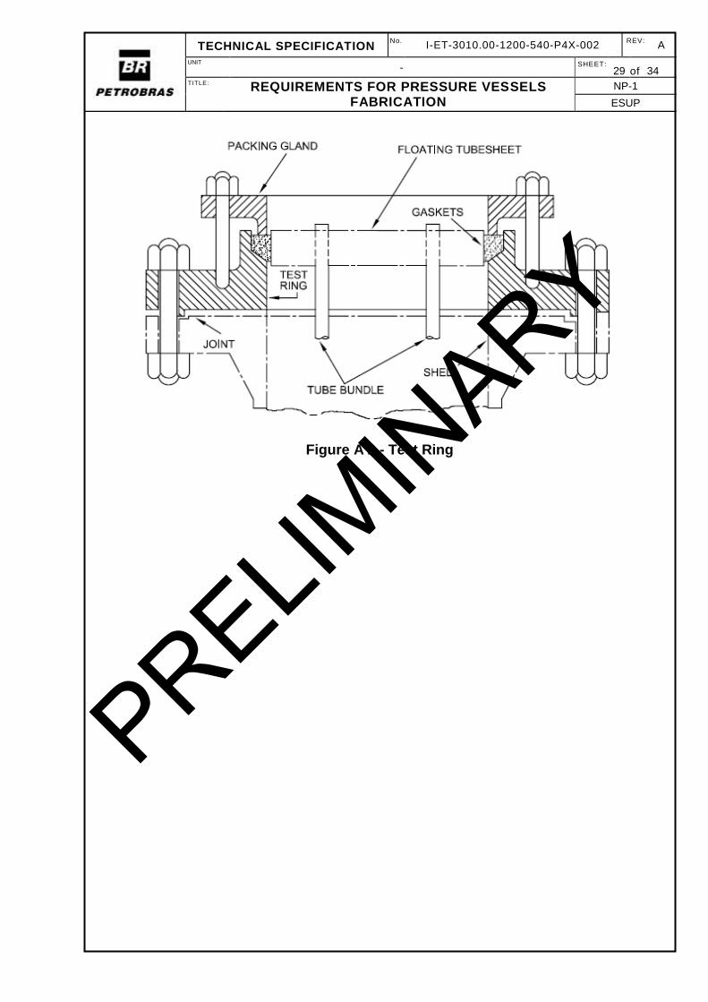
Equipment with floating head shall be fitted with a test ring, which allows pressurization of the shell for the hydrostatic test. See Figure A 2.
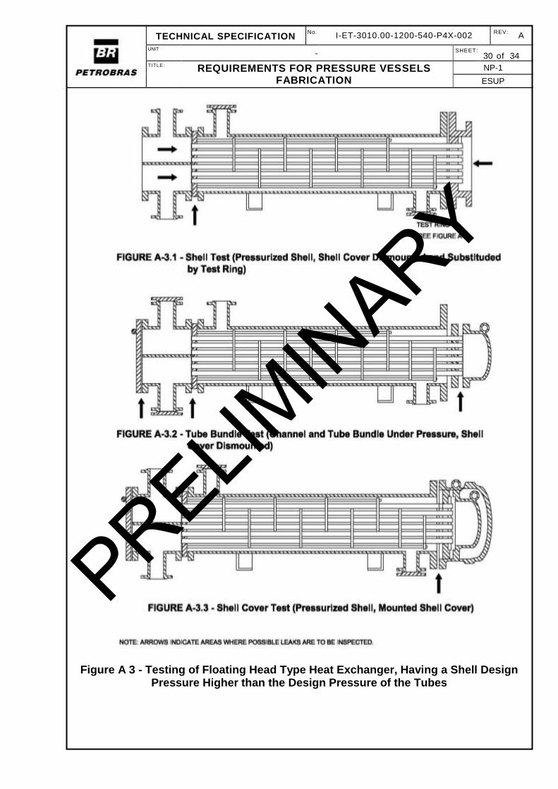
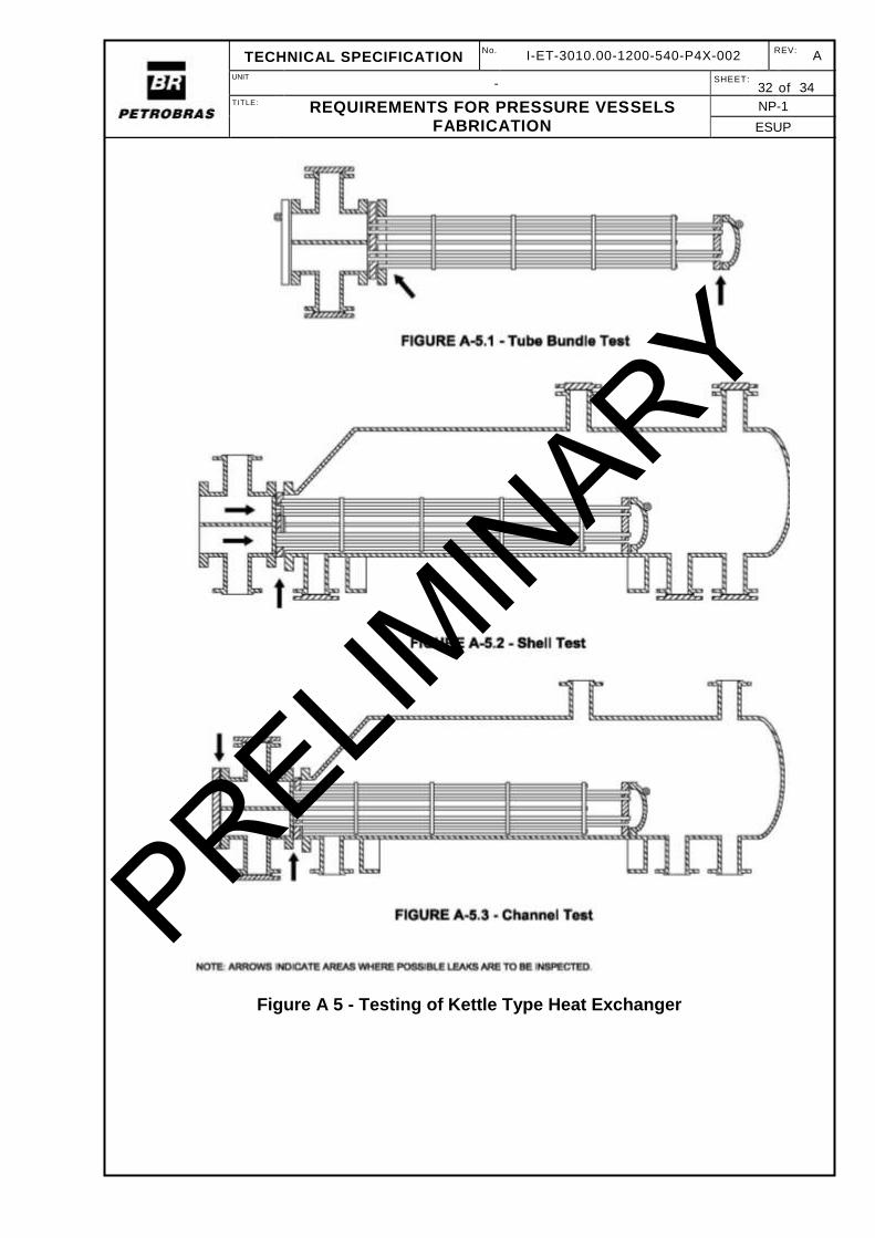
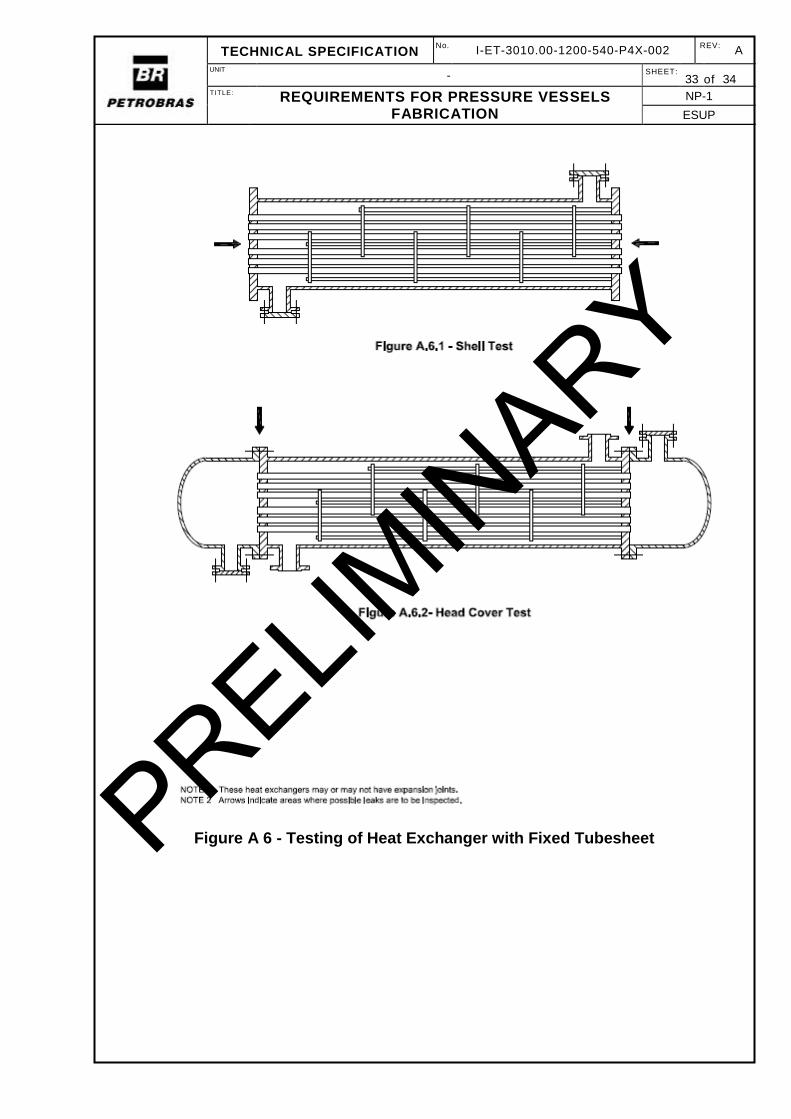
Testing sequence shall follow the assembly sequence of the heat exchanger. See Figure A 3 to Figure A 6, where the arrows indicate the areas where sealing shall be checked.
The shell and tube bundle shall be tested so that possible leaks in the tube expanding be checked at least from one side.
9.10 PNEUMATIC AND HYDRO-PNEUMATIC PRESSURE TESTS
Due to the serious risk they represent, these tests are only exceptionally admitted, and, for each case, there shall be previous approval of
PRELIMIN
ARY
TECHNICAL SPECIFICATION No .
I-ET-3010.00-1200-540-P4X-002 REV:
A
UNIT - SHEET:
25 of 34 TITLE: REQUIREMENTS FOR PRESSURE VESSELS
FABRICATION
NP-1
ESUP
PETROBRAS. In this case, a specific procedure shall be issued and submitted for PETROBRAS approval.
PRELIMIN
ARY
TECHNICAL SPECIFICATION No .
I-ET-3010.00-1200-540-P4X-002 REV:
A
UNIT - SHEET:
26 of 34 TITLE: REQUIREMENTS FOR PRESSURE VESSELS
FABRICATION
NP-1
ESUP
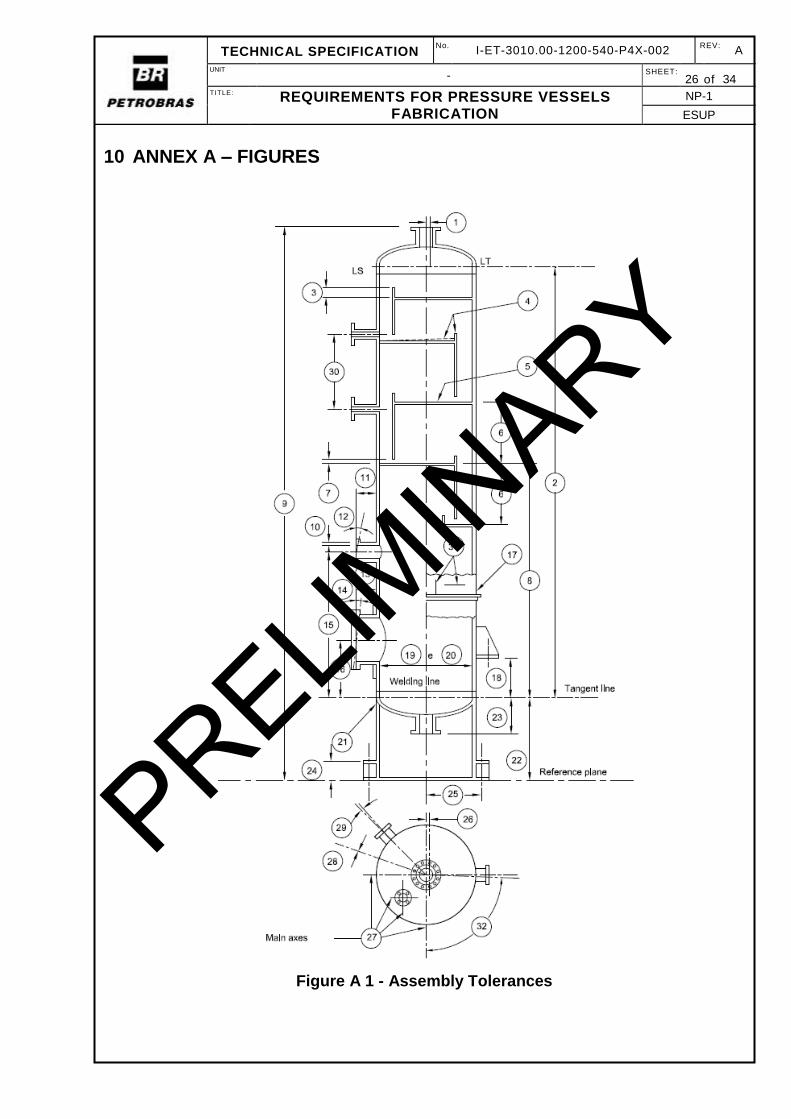
10 ANNEX A – FIGURES
Figure A 1 - Assembly Tolerances
PRELIMIN
ARY
TECHNICAL SPECIFICATION No .
I-ET-3010.00-1200-540-P4X-002 REV:
A
UNIT - SHEET:
27 of 34 TITLE: REQUIREMENTS FOR PRESSURE VESSELS
FABRICATION
NP-1
ESUP
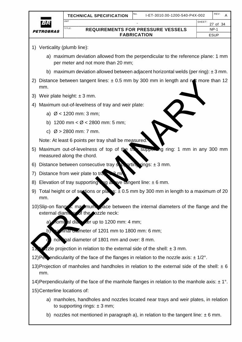
1) Verticality (plumb line):
a) maximum deviation allowed from the perpendicular to the reference plane: 1 mm
per meter and not more than 20 mm;
b) maximum deviation allowed between adjacent horizontal welds (per ring): ± 3 mm.
2) Distance between tangent lines: ± 0.5 mm by 300 mm in length and not more than 12
mm.
3) Weir plate height: ± 3 mm.
4) Maximum out-of-levelness of tray and weir plate:
a) Ø < 1200 mm: 3 mm;
b) 1200 mm < Ø < 2800 mm: 5 mm;
c) Ø > 2800 mm: 7 mm.
Note: At least 6 points per tray shall be measured.
5) Maximum out-of-levelness of top of the tray supporting ring: 1 mm in any 300 mm
measured along the chord.
6) Distance between consecutive tray supporting rings: ± 3 mm.
7) Distance from weir plate to tray: ± 3 mm.
8) Elevation of tray supporting ring above tangent line: ± 6 mm.
9) Total height or of sections or plates: ± 0.5 mm by 300 mm in length to a maximum of 20
mm.
10) Slip-on flanges: maximum space between the internal diameters of the flange and the
external diameter of the nozzle neck:
a) nominal diameter up to 1200 mm: 4 mm;
b) nominal diameter of 1201 mm to 1800 mm: 6 mm;
c) nominal diameter of 1801 mm and over: 8 mm.
11) Nozzle projection in relation to the external side of the shell: ± 3 mm.
12) Perpendicularity of the face of the flanges in relation to the nozzle axis: ± 1/2°.
13) Projection of manholes and handholes in relation to the external side of the shell: ± 6
mm.
14) Perpendicularity of the face of the manhole flanges in relation to the manhole axis: ± 1°.
15) Centerline locations of:
a) manholes, handholes and nozzles located near trays and weir plates, in relation
to supporting rings: ± 3 mm;
b) nozzles not mentioned in paragraph a), in relation to the tangent line: ± 6 mm.
PRELIMIN
ARY
TECHNICAL SPECIFICATION No .
I-ET-3010.00-1200-540-P4X-002 REV:
A
UNIT - SHEET:
28 of 34 TITLE: REQUIREMENTS FOR PRESSURE VESSELS
FABRICATION
NP-1
ESUP
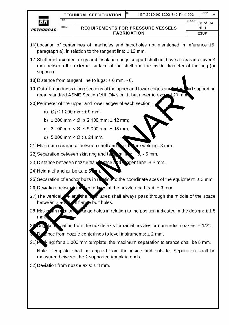
16) Location of centerlines of manholes and handholes not mentioned in reference 15,
paragraph a), in relation to the tangent line: ± 12 mm.
17) Shell reinforcement rings and insulation rings support shall not have a clearance over 4
mm between the external surface of the shell and the inside diameter of the ring (or
support).
18) Distance from tangent line to lugs: + 6 mm, - 0.
19) Out-of-roundness along sections of the upper and lower edges and in the skirt supporting
area: standard ASME Section VIII, Division 1, but never to exceed 20 mm.
20) Perimeter of the upper and lower edges of each section:
a) Ø¡ ≤ 1 200 mm: ± 9 mm;
b) 1 200 mm < Ø¡ ≤ 2 100 mm: ± 12 mm;
c) 2 100 mm < Ø¡ ≤ 5 000 mm: ± 18 mm;
d) 5 000 mm < Ø¡: ± 24 mm.
21) Maximum clearance between shell and skirt before welding: 3 mm.
22) Separation between skirt ring and tangent line: + 0, - 6 mm.
23) Distance between nozzle flange face and tangent line: ± 3 mm.
24) Height of anchor bolts: ± 3 mm.
25) Separation of anchor bolts in relation to the coordinate axes of the equipment: ± 3 mm.
26) Deviation between the centerlines of the nozzle and head: ± 3 mm.
27) The vertical line and the main axes shall always pass through the middle of the space
between 2 adjacent flange bolt holes.
28) Maximum rotation of flange holes in relation to the position indicated in the design: ± 1.5
mm.
29) Angular deviation from the nozzle axis for radial nozzles or non-radial nozzles: ± 1/2°.
30) Distance from nozzle centerlines to level instruments: ± 2 mm.
31) Peaking: for a 1 000 mm template, the maximum separation tolerance shall be 5 mm.
Note: Template shall be applied from the inside and outside. Separation shall be
measured between the 2 supported template ends.
32) Deviation from nozzle axis: ± 3 mm.
PRELIMIN
ARY
TECHNICAL SPECIFICATION No .
I-ET-3010.00-1200-540-P4X-002 REV:
A
UNIT - SHEET:
29 of 34 TITLE: REQUIREMENTS FOR PRESSURE VESSELS
FABRICATION
NP-1
ESUP
Figure A 2 - Test Ring
PRELIMIN
ARY
TECHNICAL SPECIFICATION No .
I-ET-3010.00-1200-540-P4X-002 REV:
A
UNIT - SHEET:
30 of 34 TITLE: REQUIREMENTS FOR PRESSURE VESSELS
FABRICATION
NP-1
ESUP
Figure A 3 - Testing of Floating Head Type Heat Exchanger, Having a Shell Design Pressure Higher than the Design Pressure of the Tubes
PRELIMIN
ARY

TECHNICAL SPECIFICATION No .
I-ET-3010.00-1200-540-P4X-002 REV:
A
UNIT - SHEET:
31 of 34 TITLE: REQUIREMENTS FOR PRESSURE VESSELS
FABRICATION
NP-1
ESUP
Figure A 4 - Testing of Heat Exchanger with U-Tubes, Having a Design Pressure of Shell Higher than the Design Pressure of the Tubes
PRELIMIN
ARY
TECHNICAL SPECIFICATION No .
I-ET-3010.00-1200-540-P4X-002 REV:
A
UNIT - SHEET:
32 of 34 TITLE: REQUIREMENTS FOR PRESSURE VESSELS
FABRICATION
NP-1
ESUP
Figure A 5 - Testing of Kettle Type Heat Exchanger
PRELIMIN
ARY
TECHNICAL SPECIFICATION No .
I-ET-3010.00-1200-540-P4X-002 REV:
A
UNIT - SHEET:
33 of 34 TITLE: REQUIREMENTS FOR PRESSURE VESSELS
FABRICATION
NP-1
ESUP
Figure A 6 - Testing of Heat Exchanger with Fixed Tubesheet
PRELIM
INARY

TECHNICAL SPECIFICATION No .
I-ET-3010.00-1200-540-P4X-002 REV:
A
UNIT - SHEET:
34 of 34 TITLE: REQUIREMENTS FOR PRESSURE VESSELS
FABRICATION
NP-1
ESUP
Figure A 7 - Pressurization Scheme of Hydrostatic Test
PRELIMIN
ARY