argument-based airworthiness assurance of small uas · argument-based airworthiness assurance of...
TRANSCRIPT
ARGUMENT-BASED AIRWORTHINESS ASSURANCE OF SMALL UAS Ewen Denney and Ganesh Pai
SGT / NASA Ames Research Center, Moffett Field, CA
Abstract A combination of airworthiness and various
operational restrictions are currently used to assure that unmanned aircraft system (UAS) operations can be conducted at an acceptable level of safety. We present a methodology to communicate these aspects in a unified way, providing a centralized record of safety risk management (SRM) activities. Central to our approach is the notion of structured argument, i.e., an explicit chain of reasoning linking safety substantiating evidence to the overall safety and airworthiness objectives. Our use of argumentation is motivated, in part, by the observations that: i) certain kinds of UAS operations currently require a safety case; ii) structured arguments are often a core component of modern safety cases, providing a convenient means to represent the underlying reasoning and to access the aggregated safety information; and iii) there exists a standardized graphical notation to present structured arguments, i.e., the goal structuring notation (GSN), which has been used in both civil and military aviation. To exemplify our methodology, we apply it to an unmanned rotorcraft system (URS), using GSN arguments to show the relationship between safety of URS operations, and various SRM measures including airworthiness, in particular a potential certification basis for type design assurance. The example illustrates how our approach can coexist with, and augment, existing safety processes by transforming SRM artifacts into assurance argument fragments.
Introduction Safety assurance of civil unmanned aircraft
systems (UASs), and their associated operations, poses challenges distinct from manned aircraft: i) UAS types, configurations, capabilities, and operations are substantially more diverse; ii) some safety-critical functions that were previously solely allocated to airborne equipment/crew may now also include an allocation to ground-based equipment/crew, e.g., collision detection and avoidance; and, iii) airworthiness standards, so-called
minimum operating performance standards (MOPS), and comprehensive regulations continue to be under development.
Presently, there are two avenues by which UAS operations are authorized in the US national airspace system. Public entities (e.g., government bodies such as NASA) must obtain a certificate of waiver or authorization (COA), where airworthiness is self determined against standards acceptable to the civil aviation regulator, i.e., the Federal Aviation Administration (FAA). For private entities, the FAA issues a special airworthiness certificate, where either a) the existing federal aviation regulations (FARs), which apply to manned aircraft, are tailored to a specific UAS configuration to establish a restricted category airworthiness certification basis, or b) based on the UAS configuration, a safety analysis is conducted to establish airworthiness in the experimental category, or c) an exemption from airworthiness certification is granted. Thereafter, depending on the level of airworthiness, UAS operations are usually subject to additional restrictions, e.g., limitations in altitude, range of operations, airspace category, etc. Recently, the FAA has proposed a regulatory framework targeted for small UAS1, specifically those weighing up to 55 lb. (25 kg.), in which airworthiness certification is not required, although there are numerous limitations on configurations, performance, and operations.
Thus, the trade space for UAS safety can be characterized by two extremes: at one end, similar to civil aviation, increasing vehicle reliability through airworthiness to reduce the likelihood of the system failures that may have potentially catastrophic consequences; at the other end, restricting the scope of operations to reduce the likelihood of exposure in the presence of system failures. To enable greater flexibility in UAS configurations and operations whilst also assuring safety, a combination of measures that fall between these two extremes is required.
1For more details, see: https://www.faa.gov/uas/nprm/
978-1-4799-8940-9/15/$31.00 ©2015 IEEE 5E4-1

An additional FAA requirement for approval of certain kinds of UAS operations, e.g., beyond visual line-of-sight (BVLOS), is a safety case, i.e., a type of safety risk management (SRM) document, to be supplied in a specific format, and outlining at a minimum, the environment of operations, the associated hazards, risks, and risk mitigations [1]. The international civil aviation organization (ICAO) defines a safety case as “a document which provides substantial evidence that a system to which it pertains meets its safety objectives” [2]. In general, a safety case is a comprehensive, defensible, and valid justification of the safety of a system for a given application in a defined operating environment. Associated with many modern safety cases is an additional notion of argument—i.e., a chain of reasoning connecting the overall safety objectives and required substantiating evidence—although, depending on the guidance documents or standards used, arguments may be either implicit [1, 2], or explicitly required [3].
We submit that a mechanism based on structured arguments is useful as a unified means of communicating not only the required elements of a UAS safety case, but also aspects of UAS airworthiness and operational safety, serving as a centralized record of the results of SRM activities. In this paper, we present such a mechanism—exemplified by application to an unmanned rotorcraft system (URS)—that transforms the artifacts produced from existing safety analysis processes into fragments of assurance arguments. The primary goal is show how structured arguments can communicate airworthiness requirements, in particular those relevant for type design assurance. An additional goal is to show the relationship between airworthiness and the wider objective of (system and operational) safety. The eventual aim is to use our approach also to record how the safety and airworthiness requirements have been met by a specific URS design2.
Our use of argumentation has been motivated by a number of observations: first, as mentioned earlier, a safety case is required for certain kinds of UAS operations. Second, structured arguments can capture the core reasoning underlying a safety case thereby explicitly tracing safety considerations from concept
2Although, this aspect is out of scope for this paper.
to requirements to evidence of risk mitigation and control [4]. Thus, they provide convenient access to the diverse safety information that the safety case aggregates. Third, arguments have been shown to make it easier to comprehend, and critically review a safety case [5]. Finally, to further improve clarity in presenting arguments, a relatively well-defined and standardized notation exists to graphically present structured arguments, i.e., the goal structuring notation (GSN), which has been used in both civil and military aviation [6–8]. Recently, we have also provided GSN with formal foundations, in addition to tool-based automation support [9–12].
Background In this section, we first describe the URS and its
concept of operations (CONOPS), which will serve to exemplify the use of arguments for URS safety and airworthiness assurance. Then, in brief, we present the core elements of the GSN as well as its modular extensions, which we will use subsequently in the paper to present the URS preliminary safety case; a component of this safety case is URS airworthiness.
Concept of Operations The initial scenario in the CONOPS considers
daytime operations for applications such as precision agriculture, conducted within visual line-of-sight (of the operator/visual observer) over areas of low population density, but away from other aviation activity. Extensions to this scenario include operations near other aviation activity, at nighttime, in reduced visibility conditions, and BVLOS. Future concepts extend these scenarios to other applications including pipeline monitoring, airborne surveillance, etc., over more populated areas. In general, the operations consist of six phases: mission planning, preflight, takeoff and climb, flight (including mission operations), and descent and landing. For each of these phases of operation, the flight crew have defined nominal procedures as well as contingency procedures for non-nominal scenarios, to ensure the continued safety of flight and the overall operations.
System Description The URS comprises a rotorcraft, a ground
control station (GCS), a command and control data link, and the flight crew. The rotorcraft has a maximum takeoff weight of 1000 lb., which includes
5E4-2

a maximum allowed payload of 430 lb., a physical envelope of 21 ft. x 13 ft. x 5.5 ft., an endurance range from 2.4 hours (with maximum payload) to 5 hours (with no payload), and a maximum airspeed of 105 knots, achieved using a turbine-powered tandem rotor configuration. The GCS provides a number of capabilities, including supporting operations in radio line-of-sight, health monitoring of the onboard flight-critical systems, and enabling the execution of specific commands to safely terminate flight upon the detection of anomalous behavior, onboard system failures, and during contingencies. Additionally, auxiliary systems for operational safety include a lateral and vertical containment system—providing a so-called geo-fence, i.e., a virtual, three dimensional boundary to the intended area of operations—and, potentially, a ground-based detect-and-avoid (GBDAA) system to support BVLOS, nighttime and reduced visibility operations. Based on the CONOPS and the rotorcraft characteristics, the URS warrants a determination of airworthiness, since operations over any populated areas pose an appreciable safety risk in the presence of in-flight failures.
Safety Cases and Structured Arguments An argument is a connected series of
propositions used in support of the truth of an overall proposition. We usually refer to the latter as a claim, whereas the former represents a chain of reasoning connecting the claim and the evidence. Applied to the domain of safety assurance, a safety argument comprises i) explicit safety claims, ii) a chain of reasoning that develops those claims, and iii) items of evidence to demonstrate the claims made. Moreover, a safety argument can typically contain the ways in which the stated safety goals will be developed and substantiated, the relevant context and assumptions, along with the justifications for their use. A safety case can now be thought of as a structured argument that assimilates the body of evidence and the reasoning required to conclude that a system will be safe for a defined application and operating environment. Indeed, argument-based safety cases are intended to be explicit about safety goals, evidence and the underlying reasoning. In addition to arguments, safety cases are (and should be) accompanied with a safety management plan for
updating the safety case and keeping it consistent with the system as actually operated.
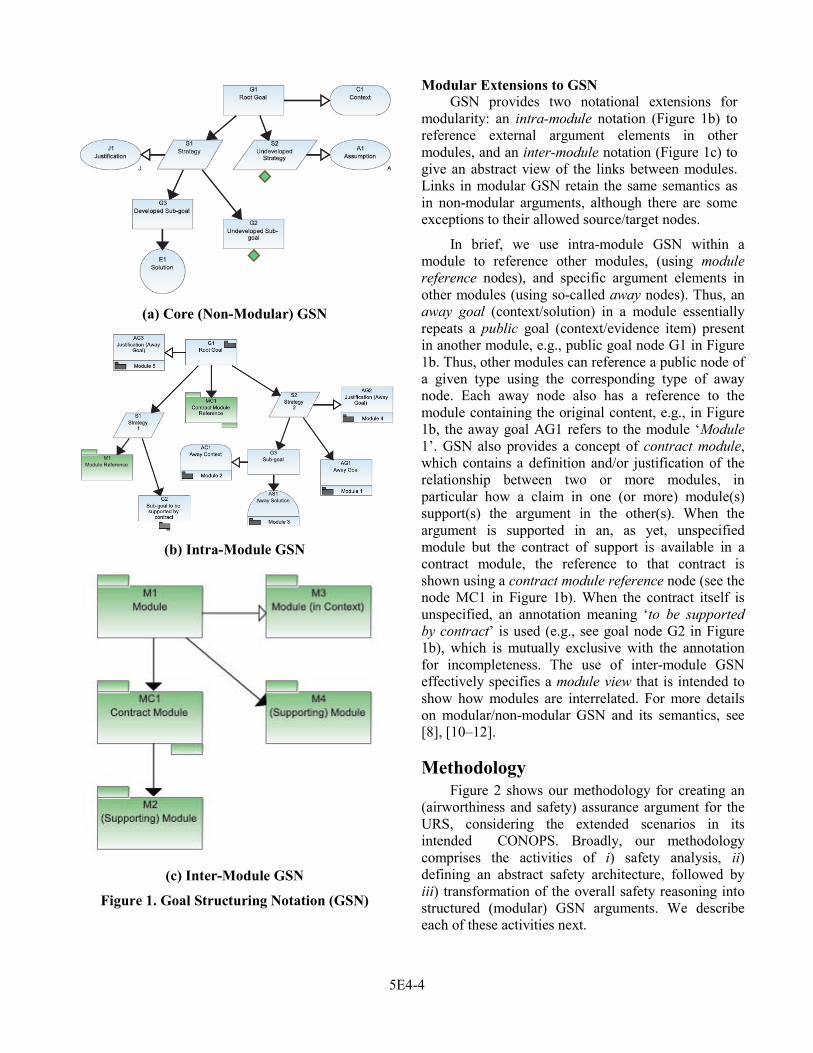
Goal Structuring Notation Core Notation
We present the elements of a safety case as an argument structure, i.e., a diagrammatic presentation of the underlying argument using the goal structuring notation (GSN). GSN provides a graphical syntax of nodes and links to represent the main elements of an argument; together they represent a chain of reasoning from premises to conclusions.
The core GSN (Figure 1a) comprises six types of nodes: goals contain the safety claims/objectives to be shown; strategies specify how claims will be refined into lower-level sub-claims; contexts supply a basis to interpret goals and strategies, and/or under which they are valid; assumptions state (intentionally) unsubstantiated assertions related to the stated claims, and the strategies used; justifications supply the rationale used for specifying a claim, or using a strategy, while solutions represent the evidence items being used to substantiate the claims made.
We indicate incompleteness using the ‘’ node annotation (read as ‘undeveloped’). Core GSN also provides two types of links, which represent specific semantic relationships between the nodes, namely a support relationship (shown as the filled arrowhead link, meaning ‘is supported by’) and a contextual relationship (shown as the hollow arrowhead link, meaning ‘in context of’).
In general, nodes refer to external items including a) artifacts such as hazard logs, requirements documents, design documents, various relevant models of the system, etc.; b) the results of engineering activities, e.g., safety, system, and software analyses, various inspections, reviews, simulations, and verification activities including different kinds of system, subsystem, and component-level testing, formal verification, etc.; and c) records from ongoing operations, as well as prior operations, if applicable. Nodes also contain metadata drawn from domain ontologies that provide supplementary and relevant domain-specific semantic information.
5E4-3
(a) Core (Non-Modular) GSN
(b) Intra-Module GSN
(c) Inter-Module GSN
Figure 1. Goal Structuring Notation (GSN)
Modular Extensions to GSN GSN provides two notational extensions for
modularity: an intra-module notation (Figure 1b) to reference external argument elements in other modules, and an inter-module notation (Figure 1c) to give an abstract view of the links between modules. Links in modular GSN retain the same semantics as in non-modular arguments, although there are some exceptions to their allowed source/target nodes.
In brief, we use intra-module GSN within a module to reference other modules, (using module reference nodes), and specific argument elements in other modules (using so-called away nodes). Thus, an away goal (context/solution) in a module essentially repeats a public goal (context/evidence item) present in another module, e.g., public goal node G1 in Figure 1b. Thus, other modules can reference a public node of a given type using the corresponding type of away node. Each away node also has a reference to the module containing the original content, e.g., in Figure 1b, the away goal AG1 refers to the module ‘Module 1’. GSN also provides a concept of contract module, which contains a definition and/or justification of the relationship between two or more modules, in particular how a claim in one (or more) module(s) support(s) the argument in the other(s). When the argument is supported in an, as yet, unspecified module but the contract of support is available in a contract module, the reference to that contract is shown using a contract module reference node (see the node MC1 in Figure 1b). When the contract itself is unspecified, an annotation meaning ‘to be supported by contract’ is used (e.g., see goal node G2 in Figure 1b), which is mutually exclusive with the annotation for incompleteness. The use of inter-module GSN effectively specifies a module view that is intended to show how modules are interrelated. For more details on modular/non-modular GSN and its semantics, see [8], [10–12].
Methodology Figure 2 shows our methodology for creating an
(airworthiness and safety) assurance argument for the URS, considering the extended scenarios in its intended CONOPS. Broadly, our methodology comprises the activities of i) safety analysis, ii) defining an abstract safety architecture, followed by iii) transformation of the overall safety reasoning into structured (modular) GSN arguments. We describe each of these activities next.
5E4-4

Figure 2. Methodology for Argument-Based Assurance
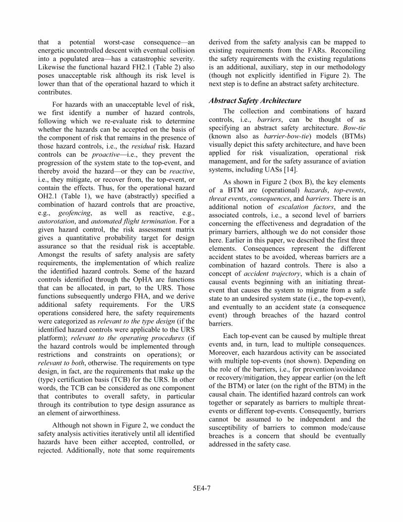
Safety Analysis The safety analysis activity (Figure 2, box A) is
conducted first as part of an operational hazard assessment (OpHA), followed by a functional hazard analysis (FHA). Essentially, this activity consists of hazard identification (HazID), risk analysis, and risk assessment. Tables 1 and 2 show excerpts of the hazard logs produced from the OpHA and FHA,
respectively, based on the CONOPS. Table 1 provides traceability to the relevant items of the CONOPS, while Table 2 identifies the relevant operational phases, and URS and operator functions. We have adapted the format of Table 1 and Table 2 from the guidance in [13], to include terminology from [14].
Table 1. Excerpt from OpHA Hazard Log for the URS
5E4-5
Table 2. Excerpt from FHA Hazard Log for the URS
Hazard Identification
In a HazID, we examine different elements of the CONOPS—in particular, the various assumptions and stakeholder needs, the airspace environment, the scope and characteristics of the required system, and the various phases of operations—to identify hazards, i.e., activities, conditions, circumstances, and entities with the potential for causing damage (to equipment, structures, and property) or harm (to humans). During OpHA we identify operational hazards—i.e., hazards encountered as part of an intended (and inherently hazardous) activity—which can be characterized using so-called top-events, the undesired system state when control over the hazardous activity has been compromised. For instance, a ‘loss of control near the containment boundary, with a deviation from the flight path’ is a top-event (Table 1, OH2.1) that, together with the activity of operating at a higher altitude near a (sparsely) populated area, represents an operational hazard. In an FHA, we identify functional hazards, i.e., deviations such as functional failures in both URS and operator functions. Functional hazards can be considered as a subset of the set of threat events, i.e., the initiating events of a causal chain where the system migrates from a safe state to an undesired state (the top-event) and eventually to an accident state. For example, a failure in the flight path control function (Table 2, FH2.1) can contribute to an energetic and uncontrolled
descent, which can be hazardous especially if the failure occurs near the containment boundary for operations, i.e., the top-event mentioned earlier (Table 1, OH2.1). Note that although functional hazards are threat events, not all threat events need be functional hazards.
Risk Analysis and Assessment The next steps in safety risk management, after
HazID, are risk analysis, and risk assessment. The activities are identical for both OpHA and FHA, though the results produced have differing scope.
The goal of safety risk analysis is to gauge the initial level of risk posed by the identified hazards, which can be characterized through a combination of worst-case consequence severity and occurrence likelihood. The goal of safety risk assessment is to define the levels of acceptable risk. We use a risk assessment matrix [13] to gauge whether or not the risk level posed by the identified hazards are acceptable. A key component of these steps is defining UAS hazard severity categories and consequences, which are different from those for manned aircraft. For example, hull loss, which is traditionally a catastrophic consequence may not be catastrophic in the event of UAS collision into unpopulated terrain. On the other hand, the operational hazard OH2.1, identified earlier (Table 1), poses unacceptable risk; the rationale is
5E4-6
that a potential worst-case consequence—an energetic uncontrolled descent with eventual collision into a populated area—has a catastrophic severity. Likewise the functional hazard FH2.1 (Table 2) also poses unacceptable risk although its risk level is lower than that of the operational hazard to which it contributes.
For hazards with an unacceptable level of risk, we first identify a number of hazard controls, following which we re-evaluate risk to determine whether the hazards can be accepted on the basis of the component of risk that remains in the presence of those hazard controls, i.e., the residual risk. Hazard controls can be proactive—i.e., they prevent the progression of the system state to the top-event, and thereby avoid the hazard—or they can be reactive, i.e., they mitigate, or recover from, the top-event, or contain the effects. Thus, for the operational hazard OH2.1 (Table 1), we have (abstractly) specified a combination of hazard controls that are proactive, e.g., geofencing, as well as reactive, e.g., autorotation, and automated flight termination. For a given hazard control, the risk assessment matrix gives a quantitative probability target for design assurance so that the residual risk is acceptable. Amongst the results of safety analysis are safety requirements, the implementation of which realize the identified hazard controls. Some of the hazard controls identified through the OpHA are functions that can be allocated, in part, to the URS. Those functions subsequently undergo FHA, and we derive additional safety requirements. For the URS operations considered here, the safety requirements were categorized as relevant to the type design (if the identified hazard controls were applicable to the URS platform); relevant to the operating procedures (if the hazard controls would be implemented through restrictions and constraints on operations); or relevant to both, otherwise. The requirements on type design, in fact, are the requirements that make up the (type) certification basis (TCB) for the URS. In other words, the TCB can be considered as one component that contributes to overall safety, in particular through its contribution to type design assurance as an element of airworthiness.
Although not shown in Figure 2, we conduct the safety analysis activities iteratively until all identified hazards have been either accepted, controlled, or rejected. Additionally, note that some requirements
derived from the safety analysis can be mapped to existing requirements from the FARs. Reconciling the safety requirements with the existing regulations is an additional, auxiliary, step in our methodology (though not explicitly identified in Figure 2). The next step is to define an abstract safety architecture.
Abstract Safety Architecture The collection and combinations of hazard
controls, i.e., barriers, can be thought of as specifying an abstract safety architecture. Bow-tie (known also as barrier-bow-tie) models (BTMs) visually depict this safety architecture, and have been applied for risk visualization, operational risk management, and for the safety assurance of aviation systems, including UASs [14].
As shown in Figure 2 (box B), the key elements of a BTM are (operational) hazards, top-events, threat events, consequences, and barriers. There is an additional notion of escalation factors, and the associated controls, i.e., a second level of barriers concerning the effectiveness and degradation of the primary barriers, although we do not consider those here. Earlier in this paper, we described the first three elements. Consequences represent the different accident states to be avoided, whereas barriers are a combination of hazard controls. There is also a concept of accident trajectory, which is a chain of causal events beginning with an initiating threat-event that causes the system to migrate from a safe state to an undesired system state (i.e., the top-event), and eventually to an accident state (a consequence event) through breaches of the hazard control barriers.
Each top-event can be caused by multiple threat events and, in turn, lead to multiple consequences. Moreover, each hazardous activity can be associated with multiple top-events (not shown). Depending on the role of the barriers, i.e., for prevention/avoidance or recovery/mitigation, they appear earlier (on the left of the BTM) or later (on the right of the BTM) in the causal chain. The identified hazard controls can work together or separately as barriers to multiple threat-events or different top-events. Consequently, barriers cannot be assumed to be independent and the susceptibility of barriers to common mode/cause breaches is a concern that should be eventually addressed in the safety case.
5E4-7

To cover the range of hazards encountered during operations, we create a BTM for each identified operational hazard. Figure 3 gives a fragment of the BTM created for an identified hazard to the URS operations (OH2.1, Table 1), and reflects (some of) the content of the OpHA and FHA hazard logs (Tables 1 and 2). As shown, three functional hazards have been identified as threat events contributing to the loss of rotorcraft control: a failure to control the flight path (FH2.1, Table 2), loss of navigation capabilities, and a failure to detect/register adverse weather conditions (the latter two have not been shown in Table 2). A number of other threat events can be given similarly. The worst case consequence is a collision into the nearby populated terrain, with a number of intermediate preceding effects, including a breach of the containment boundary, and an energetic, uncontrolled descent (Table 1). Not all identified hazard controls need to be implemented; the choice trades off the cost of
implementing and certifying the available controls, against the overall risk to be managed. As shown (Figure 3), hazard controls are a combination of operating procedures (e.g., pre-flight checks and flight planning), airworthiness of the rotorcraft (e.g., relating to the design of control and maneuvering of the URS), redundancy in the navigation equipment, and additional equipment (e.g., containment systems). From the BTM, it is clear that airworthiness is one available hazard control mechanism, which may be classified as a system reliability barrier [14]. The corresponding requirements, in particular those relevant for design assurance (i.e., the type design requirements) follow from the specific airworthiness-related controls that will be chosen for managing safety risk. We can further categorize each type design requirement based upon the component/function of the URS to which it applies, e.g., the control system, structures, powerplant and propulsion, etc.
Figure 3. Fragment of Bow-Tie Model for the URS
The final step in our methodology will transform the reasoning underlying the safety analysis and the abstract safety architecture into an argument structure that embodies the preliminary safety case.
Transformation of Safety Reasoning The safety case, more specifically the safety
argument (Figure 2, box C), encodes the safety reasoning underlying the safety analysis, and the abstract safety architecture. Our process for safety
argument development comprises six key activities, namely: i) argument design/assembly, ii) claims definition, iii) claims refinement/composition, iv) evidence definition/selection, v) argument analysis, and vi) argument improvement. The specific details of each activity are out of scope for this paper (see [15, 16] for more details). In brief, our argument development process focuses on the data flow between the constituent activities, based upon which we can infer an intuitive ordering to the activities. In
5E4-8

general, however, argument development can be performed in a top-down, or a bottom-up manner. The former requires the definition of a high-level argument architecture, and the relevant (safety) claims, which is followed by a successive refinement into the appropriate lower-level details. The latter, in contrast, is concerned with the assembly of an argument based on the inferences that can be drawn from the available evidence.
Since the safety analysis we have performed thus far is, essentially, a concept safety analysis, i.e., a safety analysis of the CONOPS of the URS-based operations, a top-down approach for argument development is appropriate. Moreover, only the activities of argument design/assembly, claims definition, and claims refinement are relevant. The remaining activities of the argument development process will be triggered in the later stages of system development, i.e., when creating a specific URS design and implementation to meet the requirements of the TCB and, in turn, of airworthiness and operational safety. Next, we present fragments of the safety argument obtained by transforming both the safety reasoning and the safety architecture using our process for developing assurance arguments.
Structured Assurance Arguments The overall argument connects the top-level
claim (of acceptable safety in the URS-based operations) to the identified hazards, the barriers to avoid and/or contain those hazards, and eventually to the safety requirements corresponding to the underlying hazard controls.
Argument Architecture The argument architecture is an abstraction of
the overall assurance argument. We represent it as a tiered organization where each tier contains argument fragments addressing a specific assurance concern. Note that GSN does not have an explicit notion of (or notation for) argument architecture. Consequently, our representation (Figure 4) serves only to illustrate the idea informally.
As shown, the argument architecture for the URS has eight tiers: the uppermost tier (Tier 0) addresses the top-level safety claim identified above, and develops it into claims related to safety risk management for the operations detailed in the CONOPS. Then, in Tier 1 we address the operational hazards and the existing regulations, i.e., the FARs. Managing the risk associated with the former is among the core strategies underlying the safety case for the concept. Tier 2 is concerned with the identified threat and consequence events associated with each hazard detailed in Tier 1. Each hazard, in turn, can be associated with several threat and consequence events.
The categorization of threat events is the main concern of Tier 3. This tier has been introduced to map the threat events (identified in the FHA), as well as the causes of the top-event (identified in the OpHA). Although not shown in Figure 4, based on the effects of a top-event, we can define a similar tiered structure for the consequence events as a counterpart to Tier 3.
5E4-9
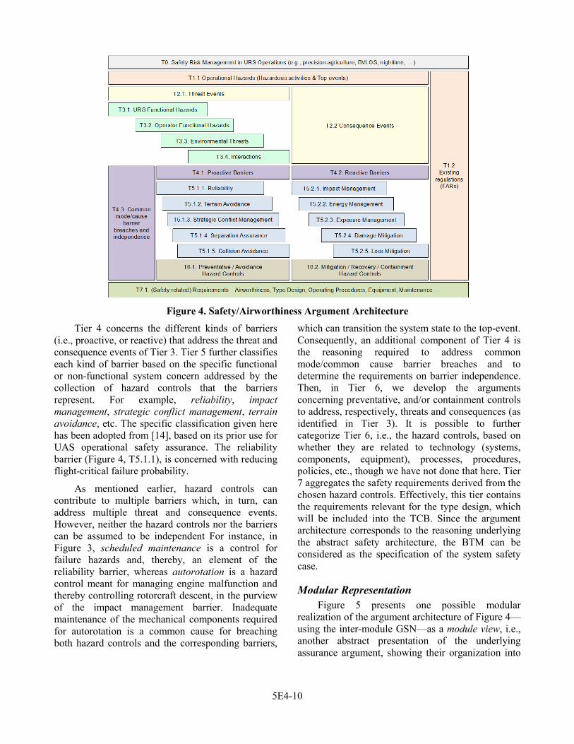
Figure 4. Safety/Airworthiness Argument Architecture
Tier 4 concerns the different kinds of barriers (i.e., proactive, or reactive) that address the threat and consequence events of Tier 3. Tier 5 further classifies each kind of barrier based on the specific functional or non-functional system concern addressed by the collection of hazard controls that the barriers represent. For example, reliability, impact management, strategic conflict management, terrain avoidance, etc. The specific classification given here has been adopted from [14], based on its prior use for UAS operational safety assurance. The reliability barrier (Figure 4, T5.1.1), is concerned with reducing flight-critical failure probability.
As mentioned earlier, hazard controls can contribute to multiple barriers which, in turn, can address multiple threat and consequence events. However, neither the hazard controls nor the barriers can be assumed to be independent For instance, in Figure 3, scheduled maintenance is a control for failure hazards and, thereby, an element of the reliability barrier, whereas autorotation is a hazard control meant for managing engine malfunction and thereby controlling rotorcraft descent, in the purview of the impact management barrier. Inadequate maintenance of the mechanical components required for autorotation is a common cause for breaching both hazard controls and the corresponding barriers,
which can transition the system state to the top-event. Consequently, an additional component of Tier 4 is the reasoning required to address common mode/common cause barrier breaches and to determine the requirements on barrier independence. Then, in Tier 6, we develop the arguments concerning preventative, and/or containment controls to address, respectively, threats and consequences (as identified in Tier 3). It is possible to further categorize Tier 6, i.e., the hazard controls, based on whether they are related to technology (systems, components, equipment), processes, procedures, policies, etc., though we have not done that here. Tier 7 aggregates the safety requirements derived from the chosen hazard controls. Effectively, this tier contains the requirements relevant for the type design, which will be included into the TCB. Since the argument architecture corresponds to the reasoning underlying the abstract safety architecture, the BTM can be considered as the specification of the system safety case.
Modular Representation Figure 5 presents one possible modular
realization of the argument architecture of Figure 4—using the inter-module GSN—as a module view, i.e., another abstract presentation of the underlying assurance argument, showing their organization into
5E4-10

different modules. Note that it is also possible to create a non-modular argument that realizes the argument architecture. However, such a structure would be appreciably large and difficult to manage and/or change.
Figure 5. Argument Architecture (Module View)
As shown (Figure 5), each of the modules M0–M6 abstracts a tier, or a combination of tiers of the argument architecture (Figure 4).
We have chosen a straightforward modularization based, intuitively, on the argument architecture. Thus, module M0 contains the arguments addressing the concerns of Tier 0 and, in part, Tier 1 (i.e., T0 and T1.1, safety risk management and operational hazards), while module M1 also contributes to realizing Tier 1 (i.e., T1.2, the existing regulations deemed applicable). Then, module M2 addresses threat events, therefore covering the concerns of Tiers 2 (in part) and 3, (i.e., T2.1, and T3.1–T3.4), whereas module M3 addresses consequence events, realizing the remaining concern of Tier 2 (i.e., T2.2). As shown in Figure 5, the modules M2 and M3 (as well as M1), support the argument in module M0 whilst also contextually invoking elements of the same. Module M4 contains arguments addressing the proactive barriers and the corresponding preventative hazard controls, thus partly addressing Tiers 4, 5, and 6 (i.e., T4.1, T5.1.1–T5.1.5, and T6.1). Likewise, module M5 contains arguments addressing the reactive barriers and the corresponding mitigation, recovery, or containment hazard controls, thus addressing additional aspects of
Tiers 4, 5 and 6 (i.e., T4.2, T5.2.1– T5.2.5, and T6.2). Finally, module M6 addresses the remaining concerns of Tier 4 (i.e., T4.3, the common mode/cause barrier breaches and barrier independence). Each of the modules M4 and M5 support the modules M2 and M1, and M3 and M1 respectively, and require support from module M6. Additionally, the modules M1, and M4–M6, collectively realize Tier 7 (T7.1), which contains the requirements on safety, airworthiness and type design assurance.
Argument Contents Now, we give fragments of the arguments in
some of the modules (namely M0, M3, and M5) such that, taken together, the fragments form an end-to-end slice of the complete preliminary safety argument (not shown). Thus, the fragments considered connect the top-level claim of the safety of URS operations to (some of) the identified hazards, the appropriate barriers to avoid/contain those hazards, and eventually to the safety requirements associated with the underlying hazard control mechanisms.
Mitigation of Hazardous Activities We address the high-level objective of the safety
of URS operations (the concerns of Tier 0 and Tier 1) in the module M0, i.e., the Main – Operational safety risk management argument module (Figure 5).
Figure 6 shows an argument fragment contained within module M0, that realizes Tier 0. Here, the main claim (G1) is that the URS operations as given in the CONOPS will pose an acceptable level of safety risk. The clarification of the acceptable level of safety, referenced in context (Figure 6, node C5), has been intentionally left unstated and informal; the idea is that this level of safety is negotiated in dialogue with the regulator, which is recorded (e.g., as an FAA issue paper), and linked to, through the GSN context node. We develop the safety claim in G1 through an argument of safety risk management of the hazardous activities of the CONOPS, as well as through compliance with the existing applicable regulations (developed further in the module M1 as indicated by the module reference node M1 in Figure 6). In turn, the former leads to a number of lower-level claims concerning the residual risk of each identified hazardous activity, e.g., as shown by the goal nodes G6, and G7.
5E4-11
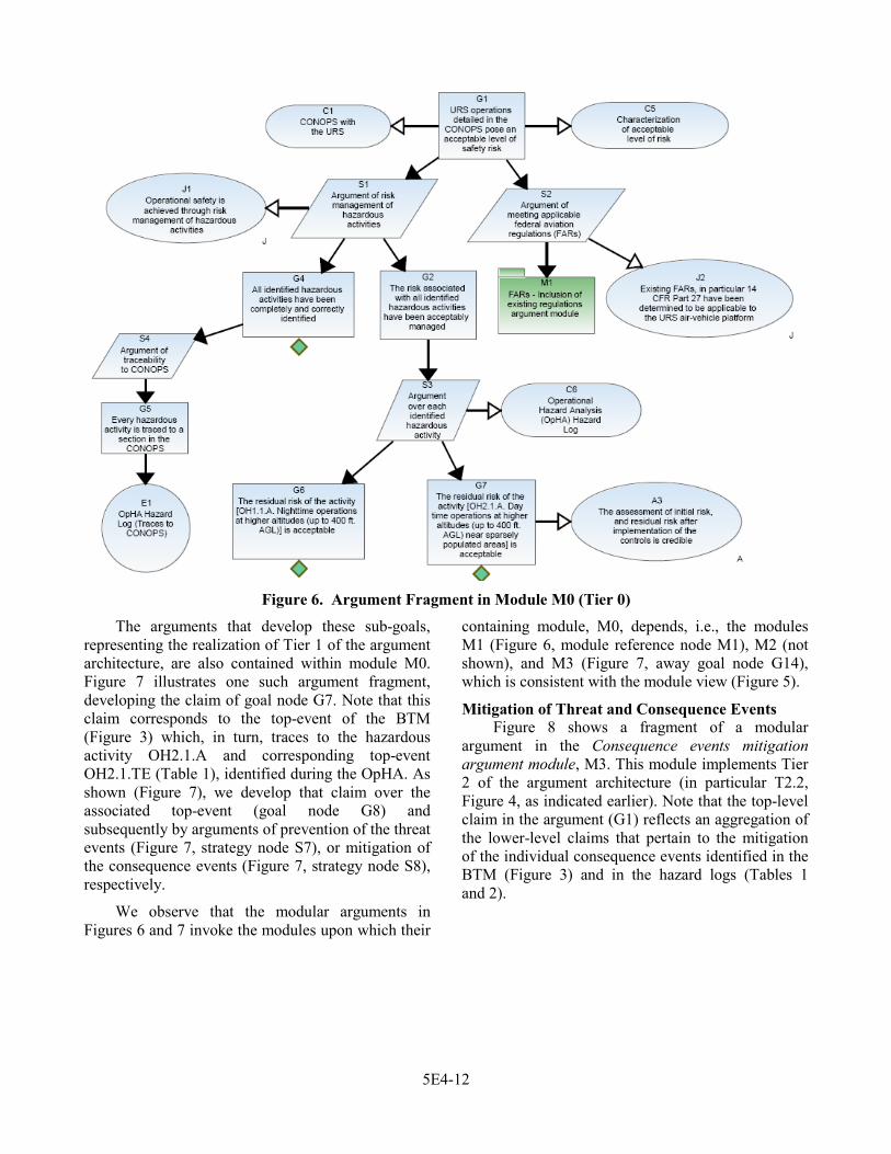
Figure 6. Argument Fragment in Module M0 (Tier 0)
The arguments that develop these sub-goals, representing the realization of Tier 1 of the argument architecture, are also contained within module M0. Figure 7 illustrates one such argument fragment, developing the claim of goal node G7. Note that this claim corresponds to the top-event of the BTM (Figure 3) which, in turn, traces to the hazardous activity OH2.1.A and corresponding top-event OH2.1.TE (Table 1), identified during the OpHA. As shown (Figure 7), we develop that claim over the associated top-event (goal node G8) and subsequently by arguments of prevention of the threat events (Figure 7, strategy node S7), or mitigation of the consequence events (Figure 7, strategy node S8), respectively.
We observe that the modular arguments in Figures 6 and 7 invoke the modules upon which their
containing module, M0, depends, i.e., the modules M1 (Figure 6, module reference node M1), M2 (not shown), and M3 (Figure 7, away goal node G14), which is consistent with the module view (Figure 5).
Mitigation of Threat and Consequence Events Figure 8 shows a fragment of a modular
argument in the Consequence events mitigation argument module, M3. This module implements Tier 2 of the argument architecture (in particular T2.2, Figure 4, as indicated earlier). Note that the top-level claim in the argument (G1) reflects an aggregation of the lower-level claims that pertain to the mitigation of the individual consequence events identified in the BTM (Figure 3) and in the hazard logs (Tables 1 and 2).
5E4-12

Figure 7. Another Argument Fragment in Module M0 (Tier 1)
Moreover, these lower-level claims have been annotated as public and, therefore, can be invoked by other modules as appropriate. Indeed, the public goal node G14 (Figure 8) is identical to the leaf away goal node G14 (Figure 7) reflecting the support link between the modules M0 and M3, as specified in the module view (Figure 5). Likewise, the leaf away goal G10 (Figure 8) invokes a public goal in module M5 (goal node G10, Figure 9), again consistent with the module view. Effectively, the core argument in
module M3 is the mitigation of the consequence events (e.g., E2.1.2, energetic uncontrolled descent) of a given top-event (e.g., OH2.1.TE) using the appropriate reactive barriers, e.g., impact management (away goal node G10), as depicted on the right side of the top-event in the BTM (Figure 3). We reference the BTM in context (Figure 8, away context node C8), reflecting the contextual link between the modules M3 and M0, consistent (again) with the module view.
5E4-13
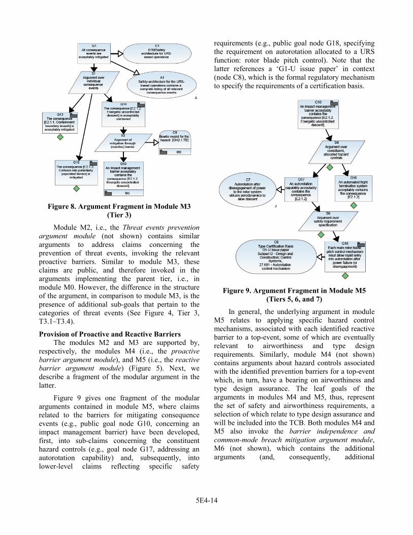
Figure 8. Argument Fragment in Module M3
(Tier 3)
Module M2, i.e., the Threat events prevention argument module (not shown) contains similar arguments to address claims concerning the prevention of threat events, invoking the relevant proactive barriers. Similar to module M3, these claims are public, and therefore invoked in the arguments implementing the parent tier, i.e., in module M0. However, the difference in the structure of the argument, in comparison to module M3, is the presence of additional sub-goals that pertain to the categories of threat events (See Figure 4, Tier 3, T3.1–T3.4).
Provision of Proactive and Reactive Barriers The modules M2 and M3 are supported by,
respectively, the modules M4 (i.e., the proactive barrier argument module), and M5 (i.e., the reactive barrier argument module) (Figure 5). Next, we describe a fragment of the modular argument in the latter.
Figure 9 gives one fragment of the modular arguments contained in module M5, where claims related to the barriers for mitigating consequence events (e.g., public goal node G10, concerning an impact management barrier) have been developed, first, into sub-claims concerning the constituent hazard controls (e.g., goal node G17, addressing an autorotation capability) and, subsequently, into lower-level claims reflecting specific safety
requirements (e.g., public goal node G18, specifying the requirement on autorotation allocated to a URS function: rotor blade pitch control). Note that the latter references a ‘G1-U issue paper’ in context (node C8), which is the formal regulatory mechanism to specify the requirements of a certification basis.
Figure 9. Argument Fragment in Module M5
(Tiers 5, 6, and 7)
In general, the underlying argument in module M5 relates to applying specific hazard control mechanisms, associated with each identified reactive barrier to a top-event, some of which are eventually relevant to airworthiness and type design requirements. Similarly, module M4 (not shown) contains arguments about hazard controls associated with the identified prevention barriers for a top-event which, in turn, have a bearing on airworthiness and type design assurance. The leaf goals of the arguments in modules M4 and M5, thus, represent the set of safety and airworthiness requirements, a selection of which relate to type design assurance and will be included into the TCB. Both modules M4 and M5 also invoke the barrier independence and common-mode breach mitigation argument module, M6 (not shown), which contains the additional arguments (and, consequently, additional
5E4-14
requirements) to assure that the barriers are not breached through common mode/cause failures.
The argument fragment as shown in Figure 9, mainly contributes towards realizing the Tiers 5, 6 and 7 of the argument architecture (Figure 4). The realization of Tier 4, in particular the various classes of reactive barriers, are realized by an argument fragment above goal node G10 (not shown), in the same manner as the root claim G1 of module M3 (Figure 8).
Concluding Remarks In this paper, we have presented a methodology
to create an explicit, and end-to-end, chain of reasoning from the claim of acceptable safety of URS operations to the requirements on safety and airworthiness. To illustrate the application of our methodology, we have created fragments of structured assurance arguments presented using the GSN.
At a high-level, the arguments reconcile i) existing FARs, and include ii) a safety analysis (specifically, operational and functional hazard analysis), as well as iii) an abstract safety architecture (i.e., BTMs). The main focus of the methodology has been to transform the reasoning underlying the latter two components. At a low-level, the arguments cover an illustrative range of concerns dealt with by specific requirements—in particular, those related to design assurance which, in turn, are relevant for type certification—derived from the safety analysis.
One of our motivations in using categories of hazard controls in the argument architecture, and subsequently creating a modular realization of the latter, is to facilitate reuse. We believe that our approach provides a means for reusing components of the analysis as building blocks for certification and operational approval. The idea is to be able to (eventually) modify those aspects of the argument and/or supporting evidence, as required by a specific UAS type and operation.
Although in current practice, there is no explicit need for argument-based airworthiness assurance, we believe that the approach may prove useful, especially for UAS. Firstly, as mentioned earlier, new regulations for UAS airworthiness continue to be under development. Although the current approach is to tailor existing regulations, the risks to be addressed
for UAS are different from those for manned aircraft, and, in many cases, tailoring existing regulations may only cover the overlapping aspects of operational safety. In other cases, tailoring regulations may be prohibitive in terms of operational flexibility. In the absence of regulations and MOPS, a safety case serves to integrate operational safety assurance and airworthiness. Indeed, it has been suggested that safety cases may be appropriate for airworthiness assurance of certain types of UAS—e.g., those possessing non-standard equipment, or novel designs/safety features [17]—and structured arguments are often a core component of safety cases. Second, the relationship between the various elements of UAS safety, part of which is airworthiness, is largely implicit. The use of structured arguments, e.g., as we have done in this paper, provides a principled way to make the relationship explicit, providing a common mechanism with which to integrate the various safety-related concerns, including airworthiness (i.e., type design assurance, maintenance, etc.), and operational procedures. Third, an assurance argument serves as an explicit record of safety rationale. It is worth noting that the explicit inclusion of rationale is one advantage of an argument-based representation, whereas in current practice, rationale is often distributed among different documents or left implicit.
Our current work has primarily considered the air-vehicle platform. Moving forward, the scope of argumentation could be extended to cover a wider range of concerns, for example requirements on the GCS, and the command and control link. We anticipate that parts of the reasoning would be similar to what we have already used, and could be captured in the form of safety case patterns [10]. Such patterns would serve two roles: i) to communicate the abstract reasoning independently of the specific details of a particular analysis and, ii) to generate concrete arguments from the safety analysis. Moreover, as described in the earlier sections of this paper, the type design requirements identified through safety analysis are an element of airworthiness. That, in turn, is a component of the safety architecture and, consequently, of the resulting preliminary safety case for the concept.
Since the TCB is, at its core, an aggregation of the type design requirements, we believe that it may
5E4-15

be feasible to extract the TCB from the assurance arguments, e.g., using metadata and querying [18], in a systematic (and ultimately automated) way. The constituent requirements of the TCB would be, effectively, leaves of the argument, and could be thought of as a view of the underlying argument. Additional views could also be constructed to communicate the key concerns and aspects of safety analysis relevant for a specific stakeholder, e.g., the civil aviation regulator.
There are justifiable reasons why normative regulations and MOPS may be preferred for regulating UAS instead of safety cases [19]. Nevertheless, our idea in this paper has been to use structured arguments within the framework of existing regulations, leveraging the existing safety processes which are applied in practice. In this paper, we have shown how the latter can be transformed into structured arguments, to serve as a central artifact in SRM activities, with traces to various other safety artifacts.
References [1] US Department of Transportation, Federal Aviation Administration (FAA), Jun. 2014, Order 8900.1, Flight Standards Information Management System, Volume 16, Unmanned Aircraft Systems. [Online]: http://fsims.faa.gov/
[2] International Civil Aviation Organization (ICAO) Sep. 2011, Guidance Material on Building a Safety Case for Delivery of an ADS-B Separation Service, v.1.0.
[3] UK Civil Aviation Authority (CAA), Nov. 2014, Small Unmanned Aircraft: Congested Areas Operating Safety Case, Information Notice IN-2014/184.
[4] Berthold, R., E. Denney, M. Fladeland, G. Pai, B. Storms, and M. Sumich, Oct. 2014, Assuring Ground Based Detect-and-Avoid for UAS Operations, 33rd IEEE/AIAA Digital Avionics Systems Conference (DASC 2014). IEEE, pp. 6A-1– 6A-16.
[5] Hawkins, R., I. Habli, T. Kelly, and J. McDermid, 2013, Assurance Cases and Prescriptive Software Safety Certification: A Comparative Study, Safety Science, vol. 59, Elsevier, pp. 55–71.
[6] UK Ministry of Defence, Jun. 2007, Safety Management Requirements for Defence Systems, Defence Standard 00-56, Issue 4.
[7] International Civil Aviation Organization (ICAO) Feb. 2008, AFI RVSM Pre-implementation Safety Case Core Document.
[8] Goal Structuring Notation Working Group, Nov. 2011, GSN Community Standard ver. 1. [Online]: http://www.goalstructuringnotation.info/
[9] Denney, E., G. Pai, and J. Pohl, Sep. 2012, AdvoCATE: An Assurance Case Automation Toolset, 31st International Conference on Computer Safety, Reliability, and Security (SAFECOMP 2012) Workshops, LNCS 7613, pp. 8–21.
[10] Denney, E., and G. Pai, Sep. 2013, A Formal Basis for Safety Case Patterns, 32nd International Conference on Computer Safety, Reliability, and Security (SAFECOMP 2013), LNCS 8153, pp. 21 – 32.
[11] Denney, E., G. Pai, and I. Whiteside, Jan. 2015, Formal Foundations for Hierarchical Safety Cases, 16th IEEE International Symposium on High Assurance Systems Engineering (HASE 2015), pp. 52–59.
[12] Denney, E., and G. Pai, Sep. 2015, Towards a Formal Basis for Modular Safety Cases, 34th International Conference on Computer Safety, Reliability, and Security (SAFECOMP 2015) (To appear).
[13] Federal Aviation Administration (FAA) Air Traffic Organization (ATO), May 2014, Safety Management System Manual Version 4.0. [Online]: http://www.faa.gov/air_traffic/publications/
[14] Williams, B., R. Clothier, N. Fulton, X. Lin, S. Johnson, and K. Cox, Jun. 2014, Building the Safety Case for UAS Operations in Support of Natural Disaster Response, 14th AIAA Aviation Technology, Integration, and Operations Conference.
[15] Denney, E., and G. Pai, Sep. 2012, A Lightweight Methodology for Safety Case Assembly, 31st International Conference on Computer Safety, Reliability, and Security (SAFECOMP 2012), LNCS 7612 pp. 1–12.
[16] Denney, E., and G. Pai, Aug. 2015, A Methodology for the Development of Assurance Arguments for Unmanned Aircraft Systems, 33rd
5E4-16

International System Safety Conference (ISSC 2015) (To appear).
[17] Clothier, R., B. Williams, M. Wade, J. Coyne, and A. Washington, Feb. 2015, Challenges to the Development of an Airworthiness Regulatory Frame-work for Unmanned Aircraft Systems, 16th Australian International Aerospace Congress.
[18] Denney, E., D. Naylor, and G. Pai, Sep. 2014, Querying Safety Cases, 33rd International Conference on Computer Safety, Reliability, and Security (SAFECOMP 2014). LNCS 8666, pp. 294–309.
[19] Haddon, D., and C. Whittaker, Aug. 2002, Aircraft Airworthiness Certification Standards for Civil UAVs. Safety Regulation Group, UK Civil Aviation Authority (CAA), 2002.
Acknowledgements This work was supported by NASA ARMD
through the UAS Integration in the NAS project of the Integrated Systems Research program. We thank our colleagues at NASA Langley, who developed the CONOPS and contributed to the HazID.
Disclaimer The opinions expressed in this paper and any
errors are those of the authors, and do not reflect the views of SGT, Inc., NASA, or the U.S. Government.
Email Addresses Ewen Denney: [email protected]
Ganesh Pai: [email protected]
34th Digital Avionics Systems Conference September 13-17, 2015
5E4-17