aquastar 125b natural gas and propane model manual
TRANSCRIPT

WARNING: Improper installation, adjustment,alteration, service or maintenance can cause injury orproperty damage. Refer to this manual. For assistanceor additional information consult a qualified installer,service agency or the gas supplier.Upon completion of the installation, these instructionsshould be handed to the user of the appliance for futurereference.In the Commonwealth of Massachusetts this productmust be installed by a licensed plumber or gas fitter.
INSTALLATION AND OPERATING INSTRUCTIONS FOR AUTOMATICINSTANTANEOUS TYPE WATER HEATERS FOR USE WITH NATURAL ANDLIQUEFIED PETROLEUM GAS
MODEL 125B LP and 125B NG (Flow Modulated)Suitable for heating potable water only
Not approved for space heating purposesIntended for variable flow applications with steady cold water inlet temperatures only
WARNINGIf the information in this manual is not followed exactly, afire or explosion may result causing property damage,personal injury or death.
FOR YOUR SAFETYDo not store or use gasoline or other flammable,combustible or corrosive vapors and liquids in the vicinityof this or any other appliance.
WHAT TO DO IF YOU SMELL GAS- Do not try to light any appliance.- Do not touch any electrical switch; do not use any
phone in your building.- Immediately call your gas supplier from a neighbor’s
phone. Follow the gas supplier’s instructions.- If you cannot reach your gas supplier, call the fire
department.- Installation and service must be performed by a
qualified installer, service agency or the gas supplier.
Specifications ....................................... Page 2Rules for safe operation ..................... Page 4Locating the Heater ............................ Page 4Combustion Air Requirements .......... Page 5Mounting the Heater ........................... Page 6Venting the Heater .............................. Page 7Gas Connections ..............................Page 10Water Connections ...........................Page 12Safety before lighting the pilot .......Page 12Lighting instructions ..........................Page 13Setting water temperature ...............Page 13Maintenance & Service ....................Page 13Trouble Shooting ................................Page 14Diagram of AquaStar ........................Page 19Components and Parts List ............ Page 20Warranty ............................................. Page 22
TABLE OF CONTENTS
6 72
0 6
07 0
30
US
(05.
12) A
L
2 6 720 607 030
This well engineered, gas water heater has all the fea-tures a water heater should have:It operates on the principle of heating water instantaneously“on demand”. When a hot water faucet is opened, cold waterflows through the coils of the heat exchanger in the Aquastar.This same flow opens the gas valve, and the burners areignited by the pilot flame. The heat exchanger coils absorbthe heat generated by the burners and transfer heat to thewater. When the hot water faucet is shut off, the gas valveautomatically closes and the burners turn off. Your hot wa-ter faucet is an ignition key to turn on the water heater,giving you control over your hot water energy use. Eachtime you turn off your hot water faucet, you also shut offthe water heater.
FEATURES
- High Quality Materials for Long Working Life.
- Copper heating coils for endless supply of hot water.
- Burner output proportional to hot water flow demand formaximum energy efficiency.
- Safety thermocouple at pilot burner.
- Automatic overheating protection shut-off sensor.
- Flue gas safety device.
- Stainless steel burners with stabilized blue flame.
- Built-in corrosion resistant draft inducer.
- Compact space saver: mounts on a wall with two hooks.
- Easily removable one-piece cover.
- Easy one person installation.
- Adjustable water flow restrictor to ensure that water flowdemand will not exceed the heating capacity of the heater.
- Easy pilot flame lighting with push button piezo ignition.
BOSCH is constantly improving our products, thereforespecifications are subject to change without prior notice.
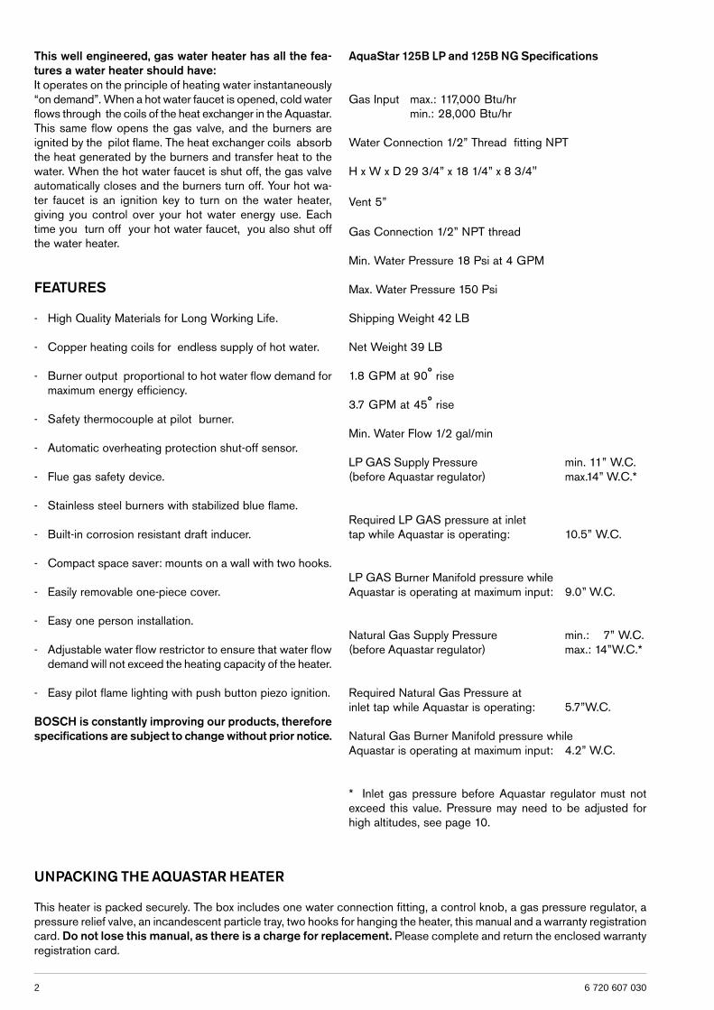
AquaStar 125B LP and 125B NG Specifications
Gas Input max.: 117,000 Btu/hrmin.: 28,000 Btu/hr
Water Connection 1/2” Thread fitting NPT
H x W x D 29 3/4” x 18 1/4” x 8 3/4"
Vent 5”
Gas Connection 1/2” NPT thread
Min. Water Pressure 18 Psi at 4 GPM
Max. Water Pressure 150 Psi
Shipping Weight 42 LB
Net Weight 39 LB
1.8 GPM at 90° rise
3.7 GPM at 45° rise
Min. Water Flow 1/2 gal/min
LP GAS Supply Pressure min. 11” W.C.(before Aquastar regulator) max.14” W.C.*
Required LP GAS pressure at inlettap while Aquastar is operating: 10.5” W.C.
LP GAS Burner Manifold pressure whileAquastar is operating at maximum input: 9.0” W.C.
Natural Gas Supply Pressure min.: 7” W.C.(before Aquastar regulator) max.: 14”W.C.*
Required Natural Gas Pressure atinlet tap while Aquastar is operating: 5.7”W.C.
Natural Gas Burner Manifold pressure whileAquastar is operating at maximum input: 4.2” W.C.
* Inlet gas pressure before Aquastar regulator must notexceed this value. Pressure may need to be adjusted forhigh altitudes, see page 10.
UNPACKING THE AQUASTAR HEATER
This heater is packed securely. The box includes one water connection fitting, a control knob, a gas pressure regulator, apressure relief valve, an incandescent particle tray, two hooks for hanging the heater, this manual and a warranty registrationcard. Do not lose this manual, as there is a charge for replacement. Please complete and return the enclosed warrantyregistration card.
36 720 607 030
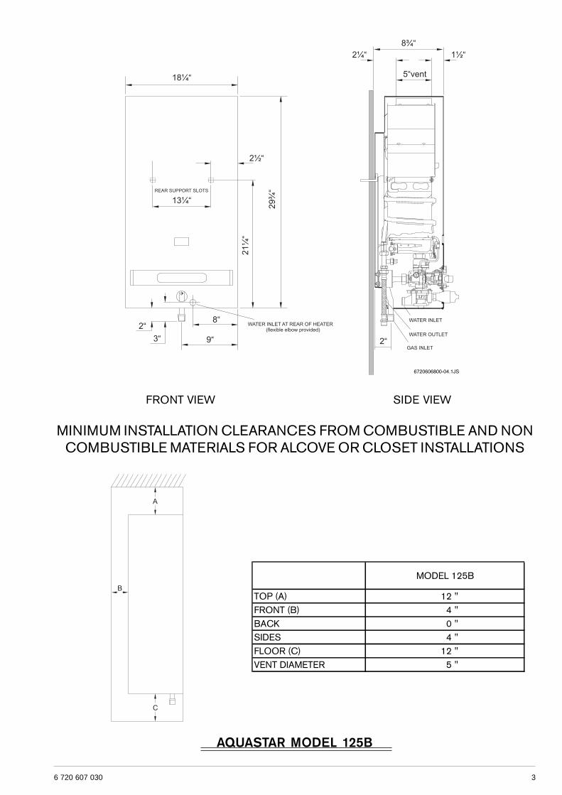
MINIMUM INSTALLATION CLEARANCES FROM COMBUSTIBLE AND NONCOMBUSTIBLE MATERIALS FOR ALCOVE OR CLOSET INSTALLATIONS
FRONT VIEW SIDE VIEW
AQUASTAR MODEL 125B
MODEL 125B
TOP (A) 12 "FRONT (B) 4 "BACK 0 " SIDES 4 "FLOOR (C) 12 "VENT DIAMETER 5 "
4 6 720 607 030
GENERAL RULES TO FOLLOWFOR SAFE OPERATION
1. You should follow these instructions when you install yourheater. In the United States: The installation must conformwith local codes or, in the absence of local codes, theNational Fuel Gas Code ANSI Z223.1/NFPA 54.In Canada: The Installation should conform with CGAB149.(1,2) INSTALLATION CODES and /or local installationcodes.
2. Carefully plan where you install the heater. Correctcombustion air supply and flue pipe installation are veryimportant. If not installed correctly, fatal accidents can becaused by lack of air, carbon monoxide poisoning or fire.
3. The place where you install the heater must have enoughventilation. The National Fire Codes do not allow gas firedwater heater installation in bathrooms, bedrooms or anyoccupied rooms normally kept closed. See the section belowon locating the heater.
4. You must vent your heater. See section on Venting, Page6.
5. The appliance must be disconnected from the gas supplypiping system during any pressure testing at pressures inexcess of 1/2 Psig (3.5 kPa).The appliance must be isolated from the gas supply pipingsystem by closing its individual manual shutoff valve duringany pressure testing of the gas supply piping system at testpressures equal to or more than 1/2 Psig (3.5Kpa). Theappliance and its gas connection must be leak tested beforeplacing the appliance in operation.
6. Keep water heater area clear and free from combustiblesand flammable liquids. Do not locate the heater over anymaterial which might burn.
7. Correct gas pressure is critical for the optimumoperation of this heater (see specifications on page 2). Gaspiping must be sized to provide the required pressure at themaximum output of the heater, while all the other gasappliances are in operation. Check with your local gassupplier, and see the section on connecting the gas supply.
8. Should overheating occur or the gas supply fail to shutoff, turn off the gas supply at the manual gas shut off valveon the gas line.
9. Do not use this appliance if any part has been underwater.Immediately call a qualified service technician to inspectthe appliance and to replace any part of the control systemand any gas control which has been underwater.
PROPER LOCATION FOR INSTALLING YOURHEATER
Carefully select the location of your new heater. For yoursafety and for proper heater operation, you must provide anabundant supply of combustion air and a proper ventinginstallation.The heater may still operate even when improperly vented.It will, however, be less efficient and could eventually damagethe heater. It could even result in human sickness or deathdue to oxygen deprivation and carbon monoxide poisoning.Follow the guidelines below:
1. Place your heater as close to a vent or chimney aspossible.
2. National building codes require that you do not installthis appliance in bathrooms, bedrooms, unvented closet orany occupied rooms normally kept closed.
3. Simultaneous operation of other appliances such asexhaust fans, ventilation systems clothes dryers, fireplacesor wood stoves could create a vacuum effect in your homewhich could cause dangerous combustion by-products tospill back into your home rather than venting to the outsidethrough the flue. Confirm that your Aquastar is ventingproperly when all these other appliances are running. Seesection on venting.
Do not obstruct the flow of combustion and ventilationair to the appliance. If installed near a clothes dryer it isvery important that the dryer be properly vented. Failure toproperly vent a dryer could result in a gradual accumulationof lint on the water heater fin coils and burners, leading to adangerous condition of vent blockage and poor unsafecombustion.
4. Your hot water lines should be kept short to save energy.It is always best to have hot water lines insulated.
5. This product is neither designed nor approved for outsideinstallations. This product is not approved for manufacturedhomes (mobile home), recreational vehicles (RV) or boats.Reference ANSI Z21.10.3.
WARNING: The water in this water heater is cold andalways remains cold except for the times that hot water isbeing used DO NOT INSTALL IN AN AREA WHERE ITCOULD FREEZE.
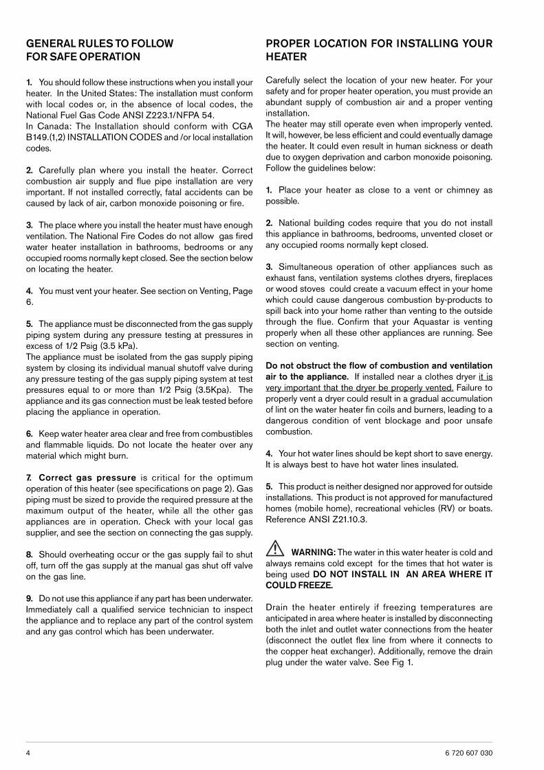
Drain the heater entirely if freezing temperatures areanticipated in area where heater is installed by disconnectingboth the inlet and outlet water connections from the heater(disconnect the outlet flex line from where it connects tothe copper heat exchanger). Additionally, remove the drainplug under the water valve. See Fig 1.
56 720 607 030
Fig. 1 - Water heater drain plug
WARNING: Flammable materials, gasoline,pressurized containers, or any other items or articlesthat are potentially fire hazards must NOT be placed onor adjacent to the heater. The appliance area must bekept free of all combustible materials, gasoline and otherflammable vapors and liquids.
COMBUSTION AIR REQUIREMENTS
The AquaStar water heater holds cold water in its copperheat exchanger and brass water valve when not in use.Because of this, any cold air that comes down through theunit’s vent pipe is capable of freezing these components.This Installation Manual specifies the minimum vertical ventpipe and the amount of combustion air required for this unit.When all requirements are followed, the unit will operateproperly and safely. However, there may still be a risk offreezing due to negative draft if all the combustion appliancesin the area are not being supplied with a sufficient amountof make-up air. A wood stove or furnace can rob the make-up air in the AquaStar’s vent pipe, leaving the cold infiltratingair capable of freezing the cold water in the AquaStar heatexchanger. More make up air is the solution. Follow theinstructions on venting and checking adequacy of make upair. A HVAC specialist should be used to design solutionsfor providing more make-up air if necessary.Observe the following instructions concerning combustionair.
Appliances located in unconfined spaces:a) An unconfined space is one whose volume is greater
than 50 cubic feet per 1000 Btu per hour of the combined rating of all appliances installed in the space. That wouldbe 5850 cubic feet for the AquaStar 125B alone.
b) In unconfined spaces in buildings of conventional frame,masonry, or metal construction, infiltration is normallyadequate to provide air for combustion, ventilation, anddilution of flue gasses.
Appliances located in confined spaces:The confined space must be provided with two permanentopenings, one commencing within 12 inches of the top andone commencing within 12 inches of the bottom of theenclosure. Each opening must have a minimum free area ofone square inch per:- 1000 Btu/hr if all air is taken from inside the building.- 2000 Btu/hr if all air is taken from the outside by horizontal
ducts.- 4000 Btu/hr if all air is taken from the outside by direct
openings or vertical ducts.Or the confined space must be provided with one permanentopening or duct that is within 12 inches of the ceiling of theenclosure. This opening must have a minimum free area ofone square inch per:- 3000 Btu/hr if all air is taken from the outside by a directopening or vertical duct.Louvers, grills and screens have a blocking effect. If theeffective free area is not known, increase the sizes of youropenings by 75% if your louvers are wood and by 30% ifyour louvers are metal. Refer to the National Fuel Gas Codefor complete information. In buildings of tight constructionall air should be taken from outside.
CLEARANCES
The Aquastar 125 B is design certified for installation on acombustible wall and for installation in an alcove or closetwith the minimum clearances to combustible and non -combustible construction listed below
A. Top 12 inches (306 mm)B. Front 4 inches (102 mm)C. Back 0 inchesD. Sides 4 inches (102mm)E. Bottom 12 inches (306 mm)
Clearance from vent is dependent upon the clearance ratingof the venting material used. For example: type B-1 vent isapproved for 1 inch clearance.
125B Air Vents(5 ½ X 5 ½ in. each)
Air Vents(10 ¾ X 10 ¾ in. each) 125B
6 6 720 607 030
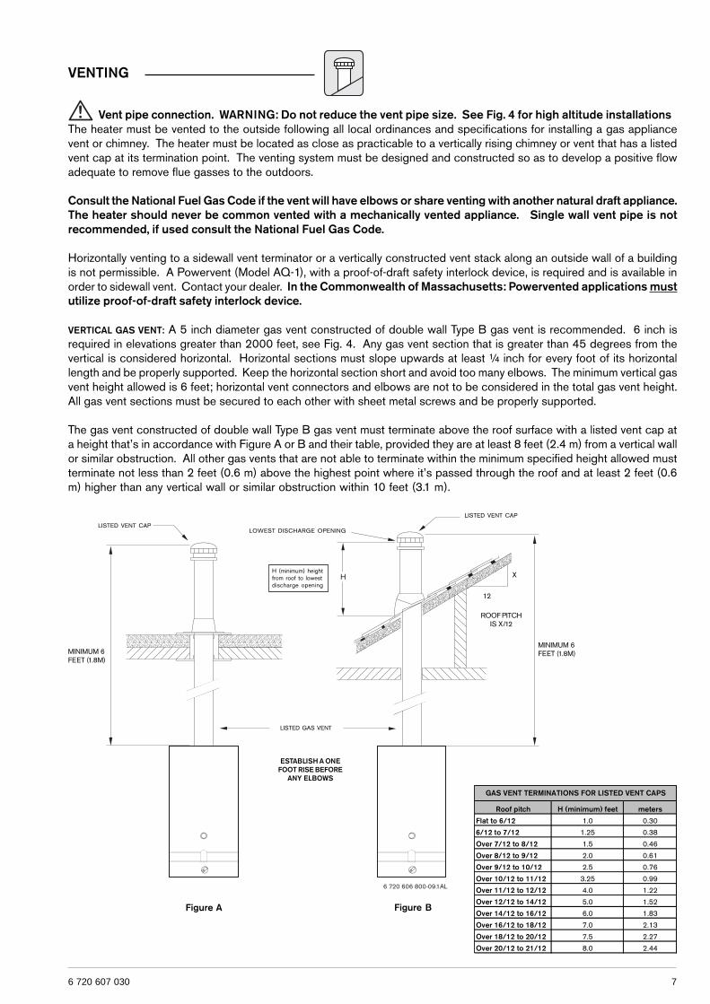
Expansion and contraction of piping due to changing watertemperature in the pipes imparts movement to the heaterwhich, if mounted directly to a brittle, friable board, such asplasterboard, can cause failure of mounting.In earthquake-prone zones, BBTNA recommends thatinstallers use a large washer and lag screw through theexisting holes used to hang the heater to affix the upperthird of the heater to the mounting board. To affix the lowerthird of the heater, BBTNA recommends that two new holesbe drilled in the heater’s frame, each one 16 inches belowthe top two holes, and that washers and lag screws be usedto secure the lower portion of the heater to a spacing board.Before installing the unit, be certain you have the correctheater for your type of Gas – Propane or Natural Gas.Identification labels are found on the shipping box, and onthe rating plate which is located on the right side panel ofthe cover. Also, each burner orifice is stamped with a number(79 for LPG and 120 for Natural Gas).
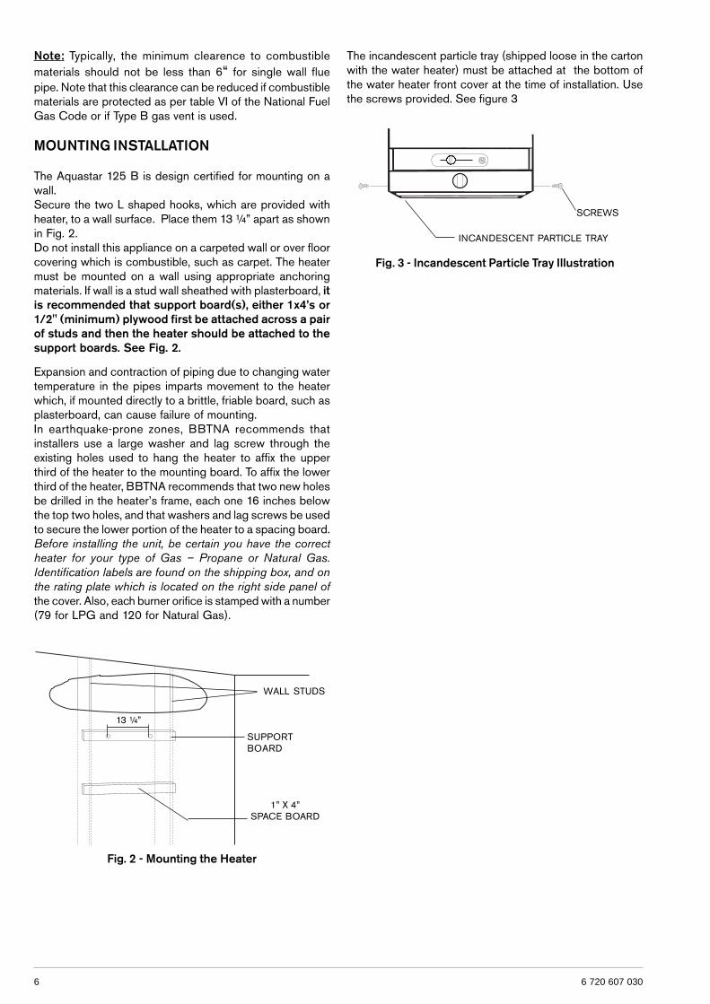
Fig. 3 - Incandescent Particle Tray Illustration
The incandescent particle tray (shipped loose in the cartonwith the water heater) must be attached at the bottom ofthe water heater front cover at the time of installation. Usethe screws provided. See figure 3
SCREWS
INCANDESCENT PARTICLE TRAY
Note: Typically, the minimum clearence to combustiblematerials should not be less than 6“ for single wall fluepipe. Note that this clearance can be reduced if combustiblematerials are protected as per table VI of the National FuelGas Code or if Type B gas vent is used.
MOUNTING INSTALLATION
The Aquastar 125 B is design certified for mounting on awall.Secure the two L shaped hooks, which are provided withheater, to a wall surface. Place them 13 ¼” apart as shownin Fig. 2.Do not install this appliance on a carpeted wall or over floorcovering which is combustible, such as carpet. The heatermust be mounted on a wall using appropriate anchoringmaterials. If wall is a stud wall sheathed with plasterboard, itis recommended that support board(s), either 1x4’s or1/2" (minimum) plywood first be attached across a pairof studs and then the heater should be attached to thesupport boards. See Fig. 2.
Fig. 2 - Mounting the Heater
WALL STUDS
1” X 4”SPACE BOARD
SUPPORTBOARD
13 ¼”
76 720 607 030
Vent pipe connection. WARNING: Do not reduce the vent pipe size. See Fig. 4 for high altitude installationsThe heater must be vented to the outside following all local ordinances and specifications for installing a gas appliancevent or chimney. The heater must be located as close as practicable to a vertically rising chimney or vent that has a listedvent cap at its termination point. The venting system must be designed and constructed so as to develop a positive flowadequate to remove flue gasses to the outdoors.
Consult the National Fuel Gas Code if the vent will have elbows or share venting with another natural draft appliance.The heater should never be common vented with a mechanically vented appliance. Single wall vent pipe is notrecommended, if used consult the National Fuel Gas Code.
Horizontally venting to a sidewall vent terminator or a vertically constructed vent stack along an outside wall of a buildingis not permissible. A Powervent (Model AQ-1), with a proof-of-draft safety interlock device, is required and is available inorder to sidewall vent. Contact your dealer. In the Commonwealth of Massachusetts: Powervented applications mustutilize proof-of-draft safety interlock device.
VERTICAL GAS VENT: A 5 inch diameter gas vent constructed of double wall Type B gas vent is recommended. 6 inch isrequired in elevations greater than 2000 feet, see Fig. 4. Any gas vent section that is greater than 45 degrees from thevertical is considered horizontal. Horizontal sections must slope upwards at least ¼ inch for every foot of its horizontallength and be properly supported. Keep the horizontal section short and avoid too many elbows. The minimum vertical gasvent height allowed is 6 feet; horizontal vent connectors and elbows are not to be considered in the total gas vent height.All gas vent sections must be secured to each other with sheet metal screws and be properly supported.
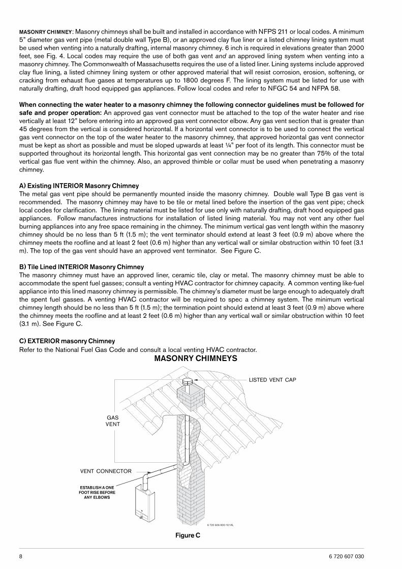
The gas vent constructed of double wall Type B gas vent must terminate above the roof surface with a listed vent cap ata height that’s in accordance with Figure A or B and their table, provided they are at least 8 feet (2.4 m) from a vertical wallor similar obstruction. All other gas vents that are not able to terminate within the minimum specified height allowed mustterminate not less than 2 feet (0.6 m) above the highest point where it’s passed through the roof and at least 2 feet (0.6m) higher than any vertical wall or similar obstruction within 10 feet (3.1 m).
VENTING
LISTED VENT CAP
LISTED VENT CAP
LISTED GAS VENT
LOWEST DISCHARGE OPENING
H (minimum) heightfrom roof to lowestdischarge opening
Figure A Figure B
ROOF PITCHIS X/12
12
X
ESTABLISH A ONEFOOT RISE BEFORE
ANY ELBOWS
MINIMUM 6FEET (1.8M)
MINIMUM 6FEET (1.8M)
Roof pitch H (minimum) feet meters
Flat to 6/12 1.0 0.30
6/12 to 7/12 1.25 0.38
Over 7/12 to 8/12 1.5 0.46
Over 8/12 to 9/12 2.0 0.61
Over 9/12 to 10/12 2.5 0.76
Over 10/12 to 11/12 3.25 0.99
Over 11/12 to 12/12 4.0 1.22
Over 12/12 to 14/12 5.0 1.52
Over 14/12 to 16/12 6.0 1.83
Over 16/12 to 18/12 7.0 2.13
Over 18/12 to 20/12 7.5 2.27
Over 20/12 to 21/12 8.0 2.44
GAS VENT TERMINATIONS FOR LISTED VENT CAPS
8 6 720 607 030
MASONRY CHIMNEY: Masonry chimneys shall be built and installed in accordance with NFPS 211 or local codes. A minimum5” diameter gas vent pipe (metal double wall Type B), or an approved clay flue liner or a listed chimney lining system mustbe used when venting into a naturally drafting, internal masonry chimney. 6 inch is required in elevations greater than 2000feet, see Fig. 4. Local codes may require the use of both gas vent and an approved lining system when venting into amasonry chimney. The Commonwealth of Massachusetts requires the use of a listed liner. Lining systems include approvedclay flue lining, a listed chimney lining system or other approved material that will resist corrosion, erosion, softening, orcracking from exhaust flue gases at temperatures up to 1800 degrees F. The lining system must be listed for use withnaturally drafting, draft hood equipped gas appliances. Follow local codes and refer to NFGC 54 and NFPA 58.
When connecting the water heater to a masonry chimney the following connector guidelines must be followed forsafe and proper operation: An approved gas vent connector must be attached to the top of the water heater and risevertically at least 12” before entering into an approved gas vent connector elbow. Any gas vent section that is greater than45 degrees from the vertical is considered horizontal. If a horizontal vent connector is to be used to connect the verticalgas vent connector on the top of the water heater to the masonry chimney, that approved horizontal gas vent connectormust be kept as short as possible and must be sloped upwards at least ¼” per foot of its length. This connector must besupported throughout its horizontal length. This horizontal gas vent connection may be no greater than 75% of the totalvertical gas flue vent within the chimney. Also, an approved thimble or collar must be used when penetrating a masonrychimney.
A) Existing INTERIOR Masonry ChimneyThe metal gas vent pipe should be permanently mounted inside the masonry chimney. Double wall Type B gas vent isrecommended. The masonry chimney may have to be tile or metal lined before the insertion of the gas vent pipe; checklocal codes for clarification. The lining material must be listed for use only with naturally drafting, draft hood equipped gasappliances. Follow manufactures instructions for installation of listed lining material. You may not vent any other fuelburning appliances into any free space remaining in the chimney. The minimum vertical gas vent length within the masonrychimney should be no less than 5 ft (1.5 m); the vent terminator should extend at least 3 feet (0.9 m) above where thechimney meets the roofline and at least 2 feet (0.6 m) higher than any vertical wall or similar obstruction within 10 feet (3.1m). The top of the gas vent should have an approved vent terminator. See Figure C.
B) Tile Lined INTERIOR Masonry ChimneyThe masonry chimney must have an approved liner, ceramic tile, clay or metal. The masonry chimney must be able toaccommodate the spent fuel gasses; consult a venting HVAC contractor for chimney capacity. A common venting like-fuelappliance into this lined masonry chimney is permissible. The chimney’s diameter must be large enough to adequately draftthe spent fuel gasses. A venting HVAC contractor will be required to spec a chimney system. The minimum verticalchimney length should be no less than 5 ft (1.5 m); the termination point should extend at least 3 feet (0.9 m) above wherethe chimney meets the roofline and at least 2 feet (0.6 m) higher than any vertical wall or similar obstruction within 10 feet(3.1 m). See Figure C.
C) EXTERIOR masonry ChimneyRefer to the National Fuel Gas Code and consult a local venting HVAC contractor.
MASONRY CHIMNEYS
GASVENT
LISTED VENT CAP
Figure C
VENT CONNECTOR
ESTABLISH A ONEFOOT RISE BEFORE
ANY ELBOWS

96 720 607 030
To check the draft:Close all doors and windows to the outside.Turn on all appliances that force air out of the building.These include all exhaust/ventilation fans, furnaces, clothesdryers, wood burning stoves, etc.
Open all doors between the AquaStar and these otherappliances.With the control knob set fully clockwise and strong hotwater flow rate, run the unit for at least 10 minutes. The125B is equipped with a Flue Gas Sensor; it’s mounted onthe right side of the draft diverter (Flue Gas Sensor #20 onpage 17). If the main burners and the pilot flame shut offduring this test it is because the Flue Gas Sensor hasdetected inadequate venting. This is a serious health hazardand must be corrected. Poor venting can result in sootbuilding up inside the heater, overheating of the heater andfreezing of the heat exchanger in a non-freezing environmentwhen not in use, which is all a result of negative air flow.Additional combustion air and/or improved venting isnecessary to correct this.
WARNINGNote: The burners of an instantaneous “on demand” waterheater such as the AquaStar are only on at the time thathot water is actually being used, the vent pipe is thereforecold except for the short durations when hot water is beingused, it is therefore very important that the venting and airsupply be adequate to provide a good positive draft as soonas the burners turn on.The AquaStar 125B instantaneous water heaters have built-in draft diverters and are designed for indoor installationonly. The draft diverter outlet must be connected to an,unobstructed vent of the same size, or larger.
In Canada, CAN/CGA-B149 Installation Code for detailedrequirementsIn U.S.A., ANSI Z223.1 - NFPA 54, National Fuel GasCode for detailed requirements.
The vent connection for the Aquastar 125B is 5 inches.However, for installations at high altitude (over 2000 feetabove sea level) a six inch vent is required. A 5” by 6” ventadaptor must be affixed to the flue collar of the Aquastarwith at least two screws. See Fig. 4.
Fig. 4 - Vent Adaptor for High Altitude Installations
5” X 6” ADAPTORUSED ON HIGH ALTITUDE
WARNING: Failure TO INCREASE THE VENT SIZETO SIX INCHES AND/or assure that the manifold pressureis set to proper value listed for applications at high altitudeswill cause unsafe venting, asphyxiation, and will void CSACertification.
10 6 720 607 030
GAS LINE SIZING
-It is strongly recommended that the Natural Gas pipebe Black Iron pipe the entire distance from the outsidemeter to the inlet of the Aquastar regulator. 1/2” BlackIron pipe up to 10 feet, 3/4” Black Iron pipe up to 40 feetand 1” Black Iron pipe up to 150 feet distances. Flex linetubing is NOT recommended, but if used then oversizeit.-It is strongly recommended that the LP Gas pipe besemi-rigid copper or Black Iron pipe from the outsideregulator to the inlet of the Aquastar regulator. For semi-rigid copper piping: 5/8” up to 20 feet and 3/4” up to 60feet distances. For Black Iron piping: 1/2 “ up to 45 feetand 3/4” up to 160 feet distances. Flex line tubing is NOTrecommended, but if used then oversize it.THESE FIGURES ARE FOR AQUASTAR SUPPLY ONLY, ALLOTHER APPLIANCES IN THE BUILDING WILL NEED TOBE INCLUDED IN THE PIPE SIZING.
National Fuel Gas Code requires that a sediment trap (dripleg) be installed on gas appliances not so equipped. Thedrip leg must be accessible and not subject to freezingconditions. Install in accordance with the recommendationsof the serving gas supplier.
WARNING: The heater must be disconnected fromthe gas supply piping system during any pressure testing ofthat system at test pressures in excess of 0.5 psig.The water heater must be isolated from the gas supply pipingsystem by closing the manual shutoff valve during anypressure testing of the gas supply piping system at testpressures equal to or more than 0.5 psig.The water heater, including the pressure regulator providedwith it, must not be operated at gas supply pressures inexcess of 0.5 psig. If overpressure has occurred, such asthrough improper testing of the gas lines or malfunction ofthe supply system, the gas valve and regulator must bechecked for safe operation. Make sure that the regulatorvent is protected against blockage.When your connections are made, check for gas leaks atall joints (not just the ones you made). Apply some soapywater to all gas fittings and gas valve. Soap bubbles are asign of a leak.NOTE: Do not apply soap solution to pilot filter screen orpilot orifice area. If you have a leak, shut off the gas. Afterverifying that required gaskets are in place, tightenappropriate fittings to stop leak. Turn the gas on and checkagain with a soapy solution. Never test for gas leaks usinga match or flame.
MAXIMUM INLET GAS FLOW PRESSURE SETTING
Altitude Natural Gas Liquid Propaneinches W.C: inches W.C:
0' - 2.000 ft 5.7" 10.5"
2.000 ft - 4.500 ft 4.6" 8.4"
The pressure regulator provided with the heater is adjustedto deliver the proper gas pressure (as indicated on the ratingplate and in the manual for altitude up to 2000 feet (660meters) above sea level. On appliances being installed above2000 ft (660 meters) elevation, the inlet gas pressure shouldbe set at installation to the value shown below.
NOTE: The gas pressures specified below refer topressures taken at the pressure tap on the gas inlet pipejust above the regulator (See Fig. 5).These readings should be taken while the heater isoperating at full input — i.e. maximum water flow withthe temperature dial selector turned all the way clockwise.
Above 4.500 ft consult your local gas supplier.
GAS CONNECTIONS
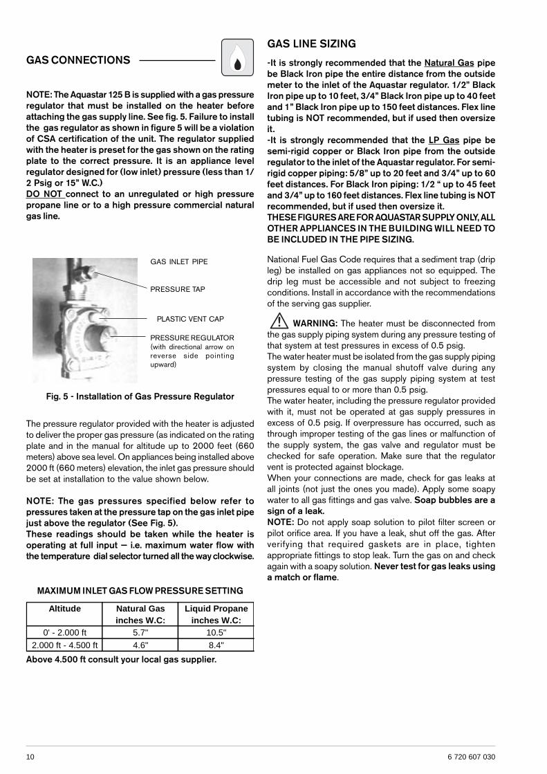
NOTE: The Aquastar 125 B is supplied with a gas pressureregulator that must be installed on the heater beforeattaching the gas supply line. See fig. 5. Failure to installthe gas regulator as shown in figure 5 will be a violationof CSA certification of the unit. The regulator suppliedwith the heater is preset for the gas shown on the ratingplate to the correct pressure. It is an appliance levelregulator designed for (low inlet) pressure (less than 1/2 Psig or 15” W.C.)DO NOT connect to an unregulated or high pressurepropane line or to a high pressure commercial naturalgas line.
Fig. 5 - Installation of Gas Pressure Regulator
GAS INLET PIPE
PRESSURE TAP
PRESSURE REGULATOR(with directional arrow onreverse side pointingupward)
PLASTIC VENT CAP
116 720 607 030
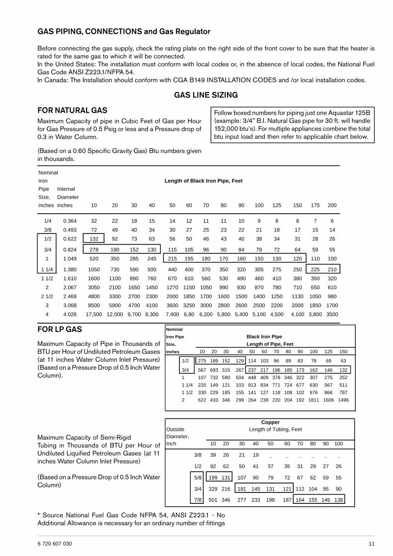
GAS PIPING, CONNECTIONS and Gas Regulator
Before connecting the gas supply, check the rating plate on the right side of the front cover to be sure that the heater israted for the same gas to which it will be connected.In the United States: The installation must conform with local codes or, in the absence of local codes, the National FuelGas Code ANSI Z223.1/NFPA 54.In Canada: The Installation should conform with CGA B149 INSTALLATION CODES and /or local installation codes.
FOR NATURAL GASMaximum Capacity of pipe in Cubic Feet of Gas per Hourfor Gas Pressure of 0.5 Psig or less and a Pressure drop of0.3 in Water Column.
Follow boxed numbers for piping just one Aquastar 125B(example: 3/4” B.I. Natural Gas pipe for 30 ft. will handle152,000 btu’s). For multiple appliances combine the totalbtu input load and then refer to applicable chart below.
(Based on a 0.60 Specific Gravity Gas) Btu numbers givenin thousands.
FOR LP GAS
Maximum Capacity of Pipe in Thousands ofBTU per Hour of Undiluted Petroleum Gases(at 11 inches Water Column Inlet Pressure)(Based on a Pressure Drop of 0.5 Inch WaterColumn).
Maximum Capacity of Semi-RigidTubing in Thousands of BTU per Hour ofUndiluted Liquified Petroleum Gases (at 11inches Water Column Inlet Pressure)
(Based on a Pressure Drop of 0.5 Inch WaterColumn)
* Source National Fuel Gas Code NFPA 54, ANSI Z223.1 - NoAdditional Allowance is necessary for an ordinary number of fittings
GAS LINE SIZING
Nominal
Iron Length of Black Iron Pipe, Feet
Pipe Internal
Size, Diameter
inches inches 10 20 30 40 50 60 70 80 90 100 125 150 175 200
1/4 0.364 32 22 18 15 14 12 11 11 10 9 8 8 7 6
3/8 0.493 72 49 40 34 30 27 25 23 22 21 18 17 15 14
1/2 0.622 132 92 73 63 56 50 46 43 40 38 34 31 28 26
3/4 0.824 278 190 152 130 115 105 96 90 84 79 72 64 59 55
1 1.049 520 350 285 245 215 195 180 170 160 150 130 120 110 100
1 1/4 1.380 1050 730 590 500 440 400 370 350 320 305 275 250 225 210
1 1/2 1.610 1600 1100 890 760 670 610 560 530 490 460 410 380 350 320
2 2.067 3050 2100 1650 1450 1270 1150 1050 990 930 870 780 710 650 610
2 1/2 2.469 4800 3300 2700 2300 2000 1850 1700 1600 1500 1400 1250 1130 1050 980
3 3.068 8500 5900 4700 4100 3600 3250 3000 2800 2600 2500 2200 2000 1850 1700
4 4.026 17,500 12,000 9,700 8,300 7,400 6,80 6,200 5,800 5,400 5,100 4,500 4,100 3,800 3500
Nominal
Iron Pipe Black Iron Pipe
Size, Length of Pipe, Feet
Inches 10 20 30 40 50 60 70 80 90 100 125 150
1/2 275 189 152 129 114 103 96 89 83 78 69 63
3/4 567 693 315 267 237 217 196 185 173 162 146 132
1 107 732 590 504 448 409 378 346 322 307 275 252
1 1/4 220 149 121 103 913 834 771 724 677 630 567 511
1 1/2 330 229 185 155 141 127 118 108 102 976 866 787
2 622 433 346 299 264 239 220 204 192 1811 1606 1496
CopperOutside Length of Tubing, FeetDiameter,Inch 10 20 30 40 50 60 70 80 90 100
3/8 39 26 21 19 _ _ _ _ _ _
1/2 92 62 50 41 37 35 31 29 27 26
5/8 199 131 107 90 79 72 67 62 59 55
3/4 329 216 181 145 131 121 112 104 95 90
7/8 501 346 277 233 198 187 164 155 146 138
12 6 720 607 030
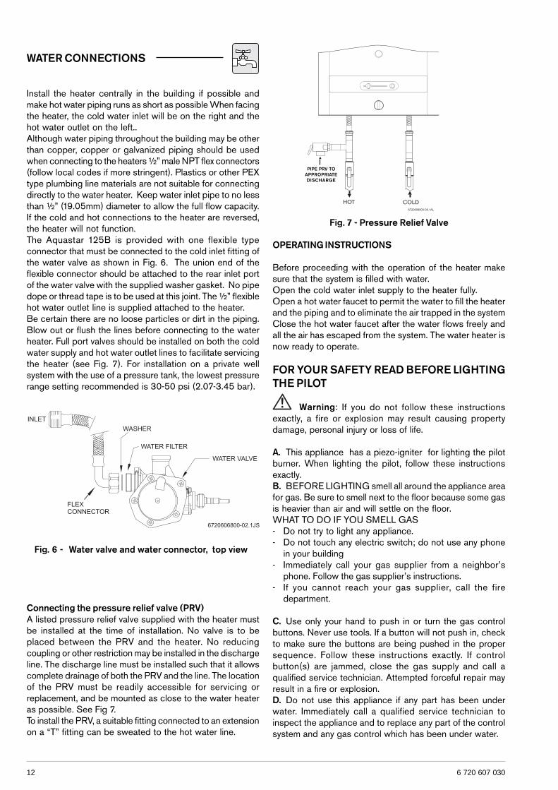
WATER CONNECTIONS
Install the heater centrally in the building if possible andmake hot water piping runs as short as possible When facingthe heater, the cold water inlet will be on the right and thehot water outlet on the left..Although water piping throughout the building may be otherthan copper, copper or galvanized piping should be usedwhen connecting to the heaters ½” male NPT flex connectors(follow local codes if more stringent). Plastics or other PEXtype plumbing line materials are not suitable for connectingdirectly to the water heater. Keep water inlet pipe to no lessthan ½” (19.05mm) diameter to allow the full flow capacity.If the cold and hot connections to the heater are reversed,the heater will not function.The Aquastar 125B is provided with one flexible typeconnector that must be connected to the cold inlet fitting ofthe water valve as shown in Fig. 6. The union end of theflexible connector should be attached to the rear inlet portof the water valve with the supplied washer gasket. No pipedope or thread tape is to be used at this joint. The ½” flexiblehot water outlet line is supplied attached to the heater.Be certain there are no loose particles or dirt in the piping.Blow out or flush the lines before connecting to the waterheater. Full port valves should be installed on both the coldwater supply and hot water outlet lines to facilitate servicingthe heater (see Fig. 7). For installation on a private wellsystem with the use of a pressure tank, the lowest pressurerange setting recommended is 30-50 psi (2.07-3.45 bar).
OPERATING INSTRUCTIONS
Before proceeding with the operation of the heater makesure that the system is filled with water.Open the cold water inlet supply to the heater fully.Open a hot water faucet to permit the water to fill the heaterand the piping and to eliminate the air trapped in the systemClose the hot water faucet after the water flows freely andall the air has escaped from the system. The water heater isnow ready to operate.
FOR YOUR SAFETY READ BEFORE LIGHTINGTHE PILOT
Warning: If you do not follow these instructionsexactly, a fire or explosion may result causing propertydamage, personal injury or loss of life.
A. This appliance has a piezo-igniter for lighting the pilotburner. When lighting the pilot, follow these instructionsexactly.B. BEFORE LIGHTING smell all around the appliance areafor gas. Be sure to smell next to the floor because some gasis heavier than air and will settle on the floor.WHAT TO DO IF YOU SMELL GAS- Do not try to light any appliance.- Do not touch any electric switch; do not use any phone
in your building- Immediately call your gas supplier from a neighbor’s
phone. Follow the gas supplier’s instructions.- If you cannot reach your gas supplier, call the fire
department.
C. Use only your hand to push in or turn the gas controlbuttons. Never use tools. If a button will not push in, checkto make sure the buttons are being pushed in the propersequence. Follow these instructions exactly. If controlbutton(s) are jammed, close the gas supply and call aqualified service technician. Attempted forceful repair mayresult in a fire or explosion.D. Do not use this appliance if any part has been underwater. Immediately call a qualified service technician toinspect the appliance and to replace any part of the controlsystem and any gas control which has been under water.
Connecting the pressure relief valve (PRV)A listed pressure relief valve supplied with the heater mustbe installed at the time of installation. No valve is to beplaced between the PRV and the heater. No reducingcoupling or other restriction may be installed in the dischargeline. The discharge line must be installed such that it allowscomplete drainage of both the PRV and the line. The locationof the PRV must be readily accessible for servicing orreplacement, and be mounted as close to the water heateras possible. See Fig 7.To install the PRV, a suitable fitting connected to an extensionon a “T” fitting can be sweated to the hot water line.
Fig. 7 - Pressure Relief Valve
PIPE PRV TOAPPROPRIATEDISCHARGE
Fig. 6 - Water valve and water connector, top view
136 720 607 030
LIGHTING INSTRUCTIONS (as seen on front coverof heater)
1. STOP! Read the safety information above on this plate.2. The Gas valve must be turned off by sliding the gas valve
button to the far left under the OFF ( ) mark.3. Wait five (5) minutes to clear out any gas. If you smell
gas, STOP! Follow “B” in the safety information aboveon this plate. If you don’t smell gas, go to next step.
4. The pilot burner is located behind the peephole in thefront center of the jacket directly below this instructionplate.
5. Slide the gas valve button to the right, under mark ( ).6. Fully depress gas valve button and light pilot by pushing
“PILOT IGNITER” button ( ). This step may have to berepeated.
7. Observe the pilot flame through the peephole. The gasvalve button should be held down at least 15 secondswith pilot burning. When the gas valve button is released,the pilot should continue to burn.
- If the gas valve button does not pop up when released,stop and immediately call your service technician or gassupplier.
- If pilot does not stay lit, repeat steps 1 through 7.- If pilot will not stay lit after several tries, slide the gas
valve button to the left, under the OFF ( ) mark and callservice technician or gas supplier.
8. Once pilot remains lit, then release gas valve button. Theheater will now fire when water is drawn at a rate greaterthan the threshold flow rate.
NOTE: If main burner should fail to ignite, make sure pilot isburning. If not, repeat lighting steps 1 through 7.NOTE: The 125B operates in two modes. See SETTINGTHE WATER TEMPERATURE.
TO TURN OFF GAS TO APPLIANCE
Slide the gas valve button to the far left, under the off ( )mark and close the gas supply to the heater.
SETTING THE WATER TEMPERATURE
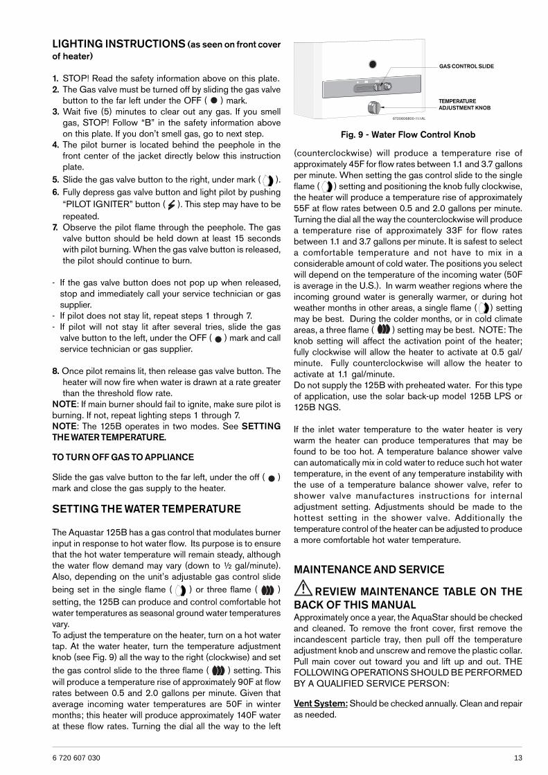
The Aquastar 125B has a gas control that modulates burnerinput in response to hot water flow. Its purpose is to ensurethat the hot water temperature will remain steady, althoughthe water flow demand may vary (down to ½ gal/minute).Also, depending on the unit’s adjustable gas control slidebeing set in the single flame ( ) or three flame ( )setting, the 125B can produce and control comfortable hotwater temperatures as seasonal ground water temperaturesvary.To adjust the temperature on the heater, turn on a hot watertap. At the water heater, turn the temperature adjustmentknob (see Fig. 9) all the way to the right (clockwise) and setthe gas control slide to the three flame ( ) setting. Thiswill produce a temperature rise of approximately 90F at flowrates between 0.5 and 2.0 gallons per minute. Given thataverage incoming water temperatures are 50F in wintermonths; this heater will produce approximately 140F waterat these flow rates. Turning the dial all the way to the left
Fig. 9 - Water Flow Control Knob
(counterclockwise) will produce a temperature rise ofapproximately 45F for flow rates between 1.1 and 3.7 gallonsper minute. When setting the gas control slide to the singleflame ( ) setting and positioning the knob fully clockwise,the heater will produce a temperature rise of approximately55F at flow rates between 0.5 and 2.0 gallons per minute.Turning the dial all the way the counterclockwise will producea temperature rise of approximately 33F for flow ratesbetween 1.1 and 3.7 gallons per minute. It is safest to selecta comfortable temperature and not have to mix in aconsiderable amount of cold water. The positions you selectwill depend on the temperature of the incoming water (50Fis average in the U.S.). In warm weather regions where theincoming ground water is generally warmer, or during hotweather months in other areas, a single flame ( ) settingmay be best. During the colder months, or in cold climateareas, a three flame ( ) setting may be best. NOTE: Theknob setting will affect the activation point of the heater;fully clockwise will allow the heater to activate at 0.5 gal/minute. Fully counterclockwise will allow the heater toactivate at 1.1 gal/minute.Do not supply the 125B with preheated water. For this typeof application, use the solar back-up model 125B LPS or125B NGS.
If the inlet water temperature to the water heater is verywarm the heater can produce temperatures that may befound to be too hot. A temperature balance shower valvecan automatically mix in cold water to reduce such hot watertemperature, in the event of any temperature instability withthe use of a temperature balance shower valve, refer toshower valve manufactures instructions for internaladjustment setting. Adjustments should be made to thehottest setting in the shower valve. Additionally thetemperature control of the heater can be adjusted to producea more comfortable hot water temperature.
MAINTENANCE AND SERVICE
REVIEW MAINTENANCE TABLE ON THEBACK OF THIS MANUALApproximately once a year, the AquaStar should be checkedand cleaned. To remove the front cover, first remove theincandescent particle tray, then pull off the temperatureadjustment knob and unscrew and remove the plastic collar.Pull main cover out toward you and lift up and out. THEFOLLOWING OPERATIONS SHOULD BE PERFORMEDBY A QUALIFIED SERVICE PERSON:
Vent System: Should be checked annually. Clean and repairas needed.
GAS CONTROL SLIDE
TEMPERATUREADJUSTMENT KNOB
14 6 720 607 030
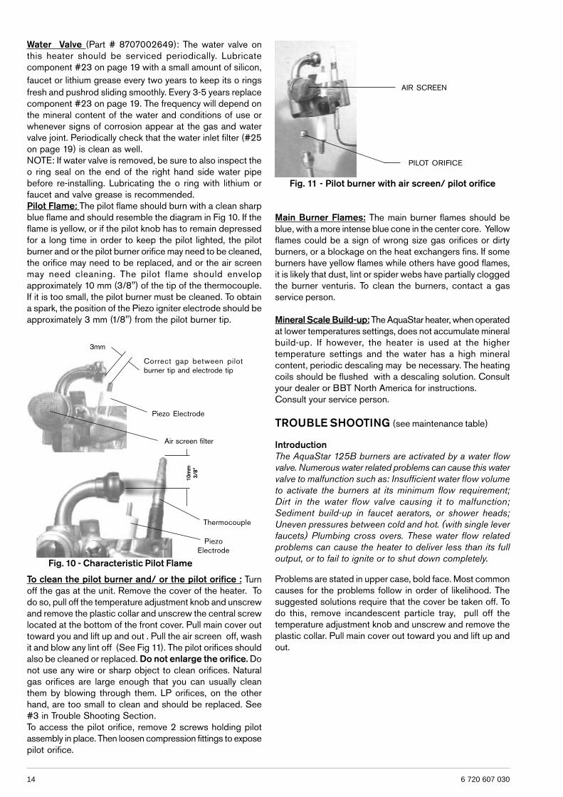
To clean the pilot burner and/ or the pilot orifice : Turnoff the gas at the unit. Remove the cover of the heater. Todo so, pull off the temperature adjustment knob and unscrewand remove the plastic collar and unscrew the central screwlocated at the bottom of the front cover. Pull main cover outtoward you and lift up and out . Pull the air screen off, washit and blow any lint off (See Fig 11). The pilot orifices shouldalso be cleaned or replaced. Do not enlarge the orifice. Donot use any wire or sharp object to clean orifices. Naturalgas orifices are large enough that you can usually cleanthem by blowing through them. LP orifices, on the otherhand, are too small to clean and should be replaced. See#3 in Trouble Shooting Section.To access the pilot orifice, remove 2 screws holding pilotassembly in place. Then loosen compression fittings to exposepilot orifice.
Fig. 10 - Characteristic Pilot Flame
Water Valve (Part # 8707002649): The water valve onthis heater should be serviced periodically. Lubricatecomponent #23 on page 19 with a small amount of silicon,faucet or lithium grease every two years to keep its o ringsfresh and pushrod sliding smoothly. Every 3-5 years replacecomponent #23 on page 19. The frequency will depend onthe mineral content of the water and conditions of use orwhenever signs of corrosion appear at the gas and watervalve joint. Periodically check that the water inlet filter (#25on page 19) is clean as well.NOTE: If water valve is removed, be sure to also inspect theo ring seal on the end of the right hand side water pipebefore re-installing. Lubricating the o ring with lithium orfaucet and valve grease is recommended.Pilot Flame: The pilot flame should burn with a clean sharpblue flame and should resemble the diagram in Fig 10. If theflame is yellow, or if the pilot knob has to remain depressedfor a long time in order to keep the pilot lighted, the pilotburner and or the pilot burner orifice may need to be cleaned,the orifice may need to be replaced, and or the air screenmay need cleaning. The pilot flame should envelopapproximately 10 mm (3/8") of the tip of the thermocouple.If it is too small, the pilot burner must be cleaned. To obtaina spark, the position of the Piezo igniter electrode should beapproximately 3 mm (1/8") from the pilot burner tip.
Main Burner Flames: The main burner flames should beblue, with a more intense blue cone in the center core. Yellowflames could be a sign of wrong size gas orifices or dirtyburners, or a blockage on the heat exchangers fins. If someburners have yellow flames while others have good flames,it is likely that dust, lint or spider webs have partially cloggedthe burner venturis. To clean the burners, contact a gasservice person.
Mineral Scale Build-up: The AquaStar heater, when operatedat lower temperatures settings, does not accumulate mineralbuild-up. If however, the heater is used at the highertemperature settings and the water has a high mineralcontent, periodic descaling may be necessary. The heatingcoils should be flushed with a descaling solution. Consultyour dealer or BBT North America for instructions.Consult your service person.
TROUBLE SHOOTING (see maintenance table)
IntroductionThe AquaStar 125B burners are activated by a water flowvalve. Numerous water related problems can cause this watervalve to malfunction such as: Insufficient water flow volumeto activate the burners at its minimum flow requirement;Dirt in the water flow valve causing it to malfunction;Sediment build-up in faucet aerators, or shower heads;Uneven pressures between cold and hot. (with single leverfaucets) Plumbing cross overs. These water flow relatedproblems can cause the heater to deliver less than its fulloutput, or to fail to ignite or to shut down completely.
Problems are stated in upper case, bold face. Most commoncauses for the problems follow in order of likelihood. Thesuggested solutions require that the cover be taken off. Todo this, remove incandescent particle tray, pull off thetemperature adjustment knob and unscrew and remove theplastic collar. Pull main cover out toward you and lift up andout.
3mm
Correct gap between pilotburner tip and electrode tip
Piezo Electrode
Air screen filter
10m
m3/
8”
PiezoElectrode
Thermocouple
Fig. 11 - Pilot burner with air screen/ pilot orifice
PILOT ORIFICE
AIR SCREEN
156 720 607 030
3. Poor thermocouple connection at the electromagnetNote: Electromagnet is part #8707201012 located on theright side of the gas valve behind the piezo push-buttonassembly. Check the tightness of the thermocoupleconnection nut at the electromagnet: The Electro-magnetconnection is a large aluminum 17mm hex head nut. Thethermocouple end is a 5 mm brass nut which screws intothe 17 mm nut. Tighten the thermocouple nut snugly but nottoo tight.
4. Poor circuit connections at the ECO (overheat sensor)or the flue gas safety device
Oxidation or looseness of the terminal connections can resultin millivolt current loss through the thermocouple safetycircuit. Clean terminals with very fine sand paper or an eraserand reconnect leads.
5. Faulty ECO (part #8707206074)If cleaning the terminals attached to the ECO did not fix theproblem, connect a jumper wire between the two wires andtry to relight the pilot. If the pilot flame now remains on,replace the ECO. If the flame still goes out when the buttonis released, the ECO is not defective. Go to next step.
6. Faulty thermocouple (part #8707206074) orelectromagnet ) Unless these 2 parts are at least 8 to10 years old, it is very unlikely that they are faulty.Before testing, reconfirm that #2 is absolutely correct,and that all connections are clean and tight.
To test the thermocouple, disconnect the thermocouple leadat the ECO. Insert a multi-meter probe into the thermocouplelead and attach or hold the other lead at the metal gasvalve (DC common). Light the pilot flame and hold button,meter reading should be 24 mVDC or more. If the reading is24 mVDC or more the thermocouple is good. To test theelectromagnet, re-connect the thermocouple lead to theECO, light pilot and hold button while taking a readingbetween the ECO and flue gas sensor leads and the metalgas valve (DC common). The reading should drop to 19mVDC or less. If it does not, replace the electromagnet.
BURNERS DO NOT IGNITE WHEN HOT WATER IS TURNEDON
1. Pilot is not on.Light the pilot. See lighting instructions.
2. Cold incoming water connection made to wrong sideof heater
Make sure cold water inlet connection is on the right side ofheater when you are facing heater.
3. Water flow rate at hot water tap is too low.Note: When the flow control knob is turned all the wayclockwise, the AquaStar models 125B require 1/2 gallonper minute flow to activate the burners. This is a flow whichwould fill a quart jar in 30 seconds. If the flow control knobis turned fully counterclockwise, a flow rate of 1.1 gpm isrequired to activate the burners.
4. Cold water inlet filter on heater is dirty.Remove filter and clean. This screen filter is located at theinlet side of the water valve (fig. 13, #25). Check and cleanfaucet aerators too.
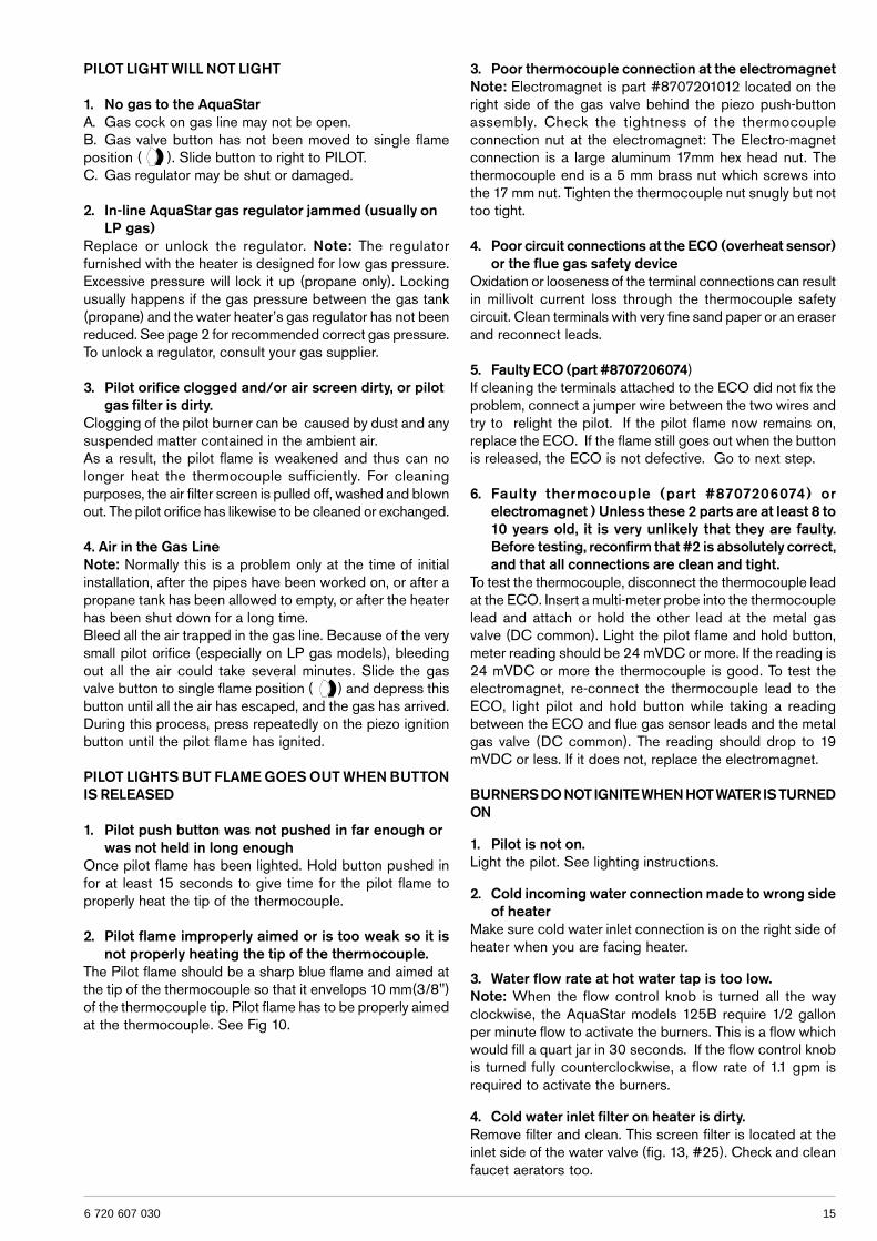
PILOT LIGHT WILL NOT LIGHT
1. No gas to the AquaStarA. Gas cock on gas line may not be open.B. Gas valve button has not been moved to single flameposition ( ). Slide button to right to PILOT.C. Gas regulator may be shut or damaged.
2. In-line AquaStar gas regulator jammed (usually onLP gas)
Replace or unlock the regulator. Note: The regulatorfurnished with the heater is designed for low gas pressure.Excessive pressure will lock it up (propane only). Lockingusually happens if the gas pressure between the gas tank(propane) and the water heater’s gas regulator has not beenreduced. See page 2 for recommended correct gas pressure.To unlock a regulator, consult your gas supplier.
3. Pilot orifice clogged and/or air screen dirty, or pilotgas filter is dirty.
Clogging of the pilot burner can be caused by dust and anysuspended matter contained in the ambient air.As a result, the pilot flame is weakened and thus can nolonger heat the thermocouple sufficiently. For cleaningpurposes, the air filter screen is pulled off, washed and blownout. The pilot orifice has likewise to be cleaned or exchanged.
4. Air in the Gas LineNote: Normally this is a problem only at the time of initialinstallation, after the pipes have been worked on, or after apropane tank has been allowed to empty, or after the heaterhas been shut down for a long time.Bleed all the air trapped in the gas line. Because of the verysmall pilot orifice (especially on LP gas models), bleedingout all the air could take several minutes. Slide the gasvalve button to single flame position ( ) and depress thisbutton until all the air has escaped, and the gas has arrived.During this process, press repeatedly on the piezo ignitionbutton until the pilot flame has ignited.
PILOT LIGHTS BUT FLAME GOES OUT WHEN BUTTONIS RELEASED
1. Pilot push button was not pushed in far enough orwas not held in long enough
Once pilot flame has been lighted. Hold button pushed infor at least 15 seconds to give time for the pilot flame toproperly heat the tip of the thermocouple.
2. Pilot flame improperly aimed or is too weak so it isnot properly heating the tip of the thermocouple.
The Pilot flame should be a sharp blue flame and aimed atthe tip of the thermocouple so that it envelops 10 mm(3/8")of the thermocouple tip. Pilot flame has to be properly aimedat the thermocouple. See Fig 10.
16 6 720 607 030
5. Crossover in household plumbingThe AquaStar burner activates when there is sufficient waterpressure drop in the AquaStar water valve assembly — i.e.when a hot water faucet is opened. If there is a crossover inthe plumbing, the necessary pressure drop in the AquaStarwill be insufficient, or totally eliminated. A plumbing crossovercan be caused by a bad washer at a single lever faucet orincorrect plumbing or a mixing valve in the line, etc. whichpermits hot and cold water to mix in the plumbing. Thecrossover will create a back pressure in the system preventingthe pressure drop in the Aquastar — i.e. cold water is enteringthe water heater from both sides and the burners will notcome on. To confirm there is no crossover in the plumbing,shut off the cold water supply to the AquaStar. Open yourhot water taps. There should not be any water flowing. Ifthere is water flowing, there is a crossover in the plumbing.This is a plumbing problem, not an Aquastar problem. Pleasecontact your plumber.
6. Water valve parts may be dirty or componentsdamaged.
Water valve and component parts must be totally free ofdirt. First check that the venturi is free of dirt particles. Inhard water areas, mineral deposits can eventually (3 to 5years in hard water areas) corrode the water valve parts toa point where they will need replacing. Any sign of moistureor corrosion at the joint of the water valve and the gas valveis a sign that the water valve assembly components need tobe serviced immediately. Note: Water valve for model 125Bis part# 8707002649 for both LP and NG models. (Contactservice person to clean water valve or replace if corrosionis present).
PILOT LIGHT GOES OUT DURING OR IMMEDIATELYAFTER HOT WATER HAS BEEN USED
1. Gas pressure too lowVery low gas pressure may be caused by low delivered gaspressure, a jammed gas regulator or undersized gas lines. Ifthe gas lines are undersized, there may still be the specifiedstatic gas line pressure. However when the water valve opens,and gas enters the burners, the pressure could drop sharply,causing the pilot flame to go out. Have a gas technicianconfirm the gas pressure both static and at maximum Btuoutput. Specifications for your heater are on page 2.
2. Pilot may be dirty or weakSee Page 14 for instructions on pilot maintenance.
3. Burners are not shutting down immediately when hotwater is turned off
Note: If burners don’t shut down immediately when the hotwater is turned off, the heater will overheat and the ECOwill shut-off the gas. Rebuild the water valve assembly.Contact service person to clean or rebuild water valve.
4. ECO (overheat sensor) tripped due to overheatingRe-ignite the appliance 10 minutes later. If it happens again,contact your service person.
5. Flue gas safety device trippedVentilate the room and re-ignite the appliance 10 minuteslater. If it happens again, contact your service person.
WATER IS TOO HOT
1. Temperature Selection too highPosition the gas control slide to the single flame ( )setting to reduce the burner output and/or turn thetemperature adjustment knob counterclockwise to lower themaximum water temperature. Note: turning the knobcounterclockwise will increase the activation flow rate.
2. Inlet water temperature is very warmIncreased seasonal ground water temperatures will affectthe hot water output temperature. Reduce the burner outputif the inlet water is very warm (60-75F) by positioning thegas control slide to the single flame ( ) setting. Thetemperature adjustment knob setting may also be lowered ifnecessary, reference SETTING THE WATERTEMPERATURE section.
WATER IS NOT HOT ENOUGH
1. Temperature selection too low.Change the setting. Turn the temperature adjustment knobclockwise and/or slide the gas control to the winter modesetting for increased burner output.Note: This will decrease the activation flow rate.
2. Btu input is too low due to insufficient gas pressureIt is extremely important for a tankless instantaneouswater heater to have the right size gas line to obtainthe correct gas pressure
See specifications on page 2. Unlike storage tank waterheaters, the burners of a tankless water heater must be verypowerful to heat water instantaneously since they do thisonly at the time hot water is actually being used. It is thereforeimperative that the gas pressure requirement be met exactly.Insufficient gas pressure will directly affect the watertemperature at the time of usage. See page 2 for correctgas pressure settings and page 10 for locations where gaspressures are taken.
3. Btu input is too low due to insufficient gas supplyMake sure your main gas line is fully opened. If using LPgas, be sure that the size of the propane tank is adequate tosupply the required gas pressure.
4. Cold water is mixing with the hot water between theAquaStar and the outlet
Compare water temperature at outlet of the AquaStar (holdthe AquaStar’s outlet pipe with your hand) and at the tap. Ifthese two are very different, check for mixing valve orplumbing crossover (see “MAIN BURNERS WILL NOTIGNITE...” paragraph #6). Where automatic “anti-scald”valves are required by code, lower the temperature settingon the AquaStar as much as possible and balance thepressure between cold and hot water after the AquaStar.
5. Parts in water valve are dirty or damaged, which willprevent the gas valve from being fully opened.
Water valve maintenance needs to be performed, see #7under BURNERS DO NOT IGNITE WHEN HOT WATERIS TURNED ON.
176 720 607 030
HOT WATER TEMPERATURE FLUCTUATES / UNITDEACTIVATED1. Unbalanced pressure in waterlinesThe added restriction caused by the Aquastar in the hotwater system can result in uneven pressures between thecold and the hot. In such cases when mixing cold water atthe tap, the lower hot water pressure may be overpoweredby the higher cold water pressure in the building, which maycause the Aquastar burners to shut down (deactivate).Do not add any flow restrictor to the shower head.Position the gas control slide to the single flame ( )setting to reduce the burner output and/or turn thetemperature adjustment knob counterclockwise to lower themaximum water temperature.Note: turning the knob counterclockwise will increasethe activation flow rate.
2. Temperature balance valvesIf the inlet water temperature to the water heater is verywarm the heater can produce temperatures that may befound to be too hot. A temperature balance shower valvecan automatically mix in cold water to reduce such hot watertemperature, in the event of any temperature instability withthe use of a temperature balance shower valve, refer toshower valve manufactures instructions for internaladjustment setting. Adjustments should be made to thehottest setting in the shower valve. Additionally thetemperature control of the heater can be adjusted to producea more comfortable hot water temperature. See SETTINGTHE WATER TEMPERATURE section.
3. Cold water is mixing with the hot water between theAquaStar and the outlet
See #6 under “Burners do Not Ignite When Hot Water IsTurned On”.
4. Inlet water pressure is erratic due to inadequate supplywater pressure or saturated pressure tank on wellsystem
For installation on a private well system with the use of apressure tank, the lowest pressure range settingrecommended is 30-50 psi (2.07-3.45 bar).
5. Gas pressure is too lowSee page 2 and 10 for correct specifications.

18 6 720 607 030
196 720 607 030
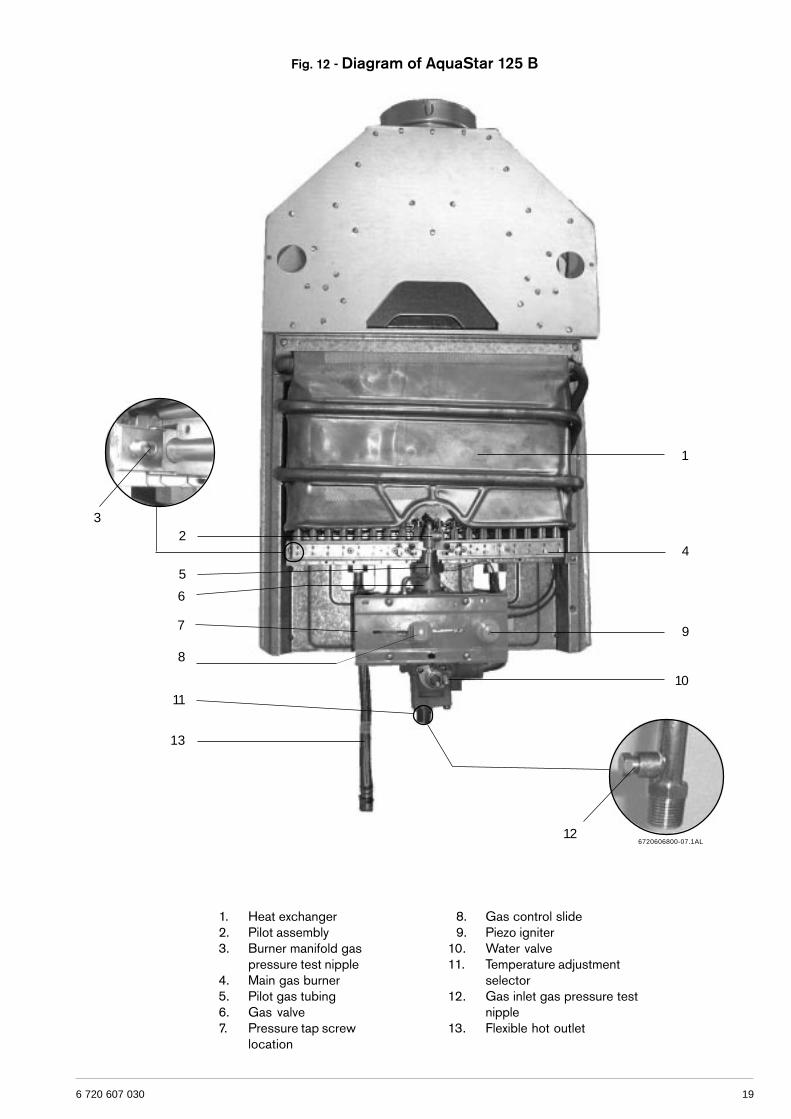
Fig. 12 - Diagram of AquaStar 125 B
1. Heat exchanger 2. Pilot assembly 3. Burner manifold gas
pressure test nipple 4. Main gas burner 5. Pilot gas tubing 6. Gas valve 7. Pressure tap screw
location
8. Gas control slide 9. Piezo igniter10. Water valve11. Temperature adjustment
selector12. Gas inlet gas pressure test
nipple13. Flexible hot outlet
5
11
1
4
9
10
3
12
2
6
7
8
13
6720606800-07.1AL
20 6 720 607 030
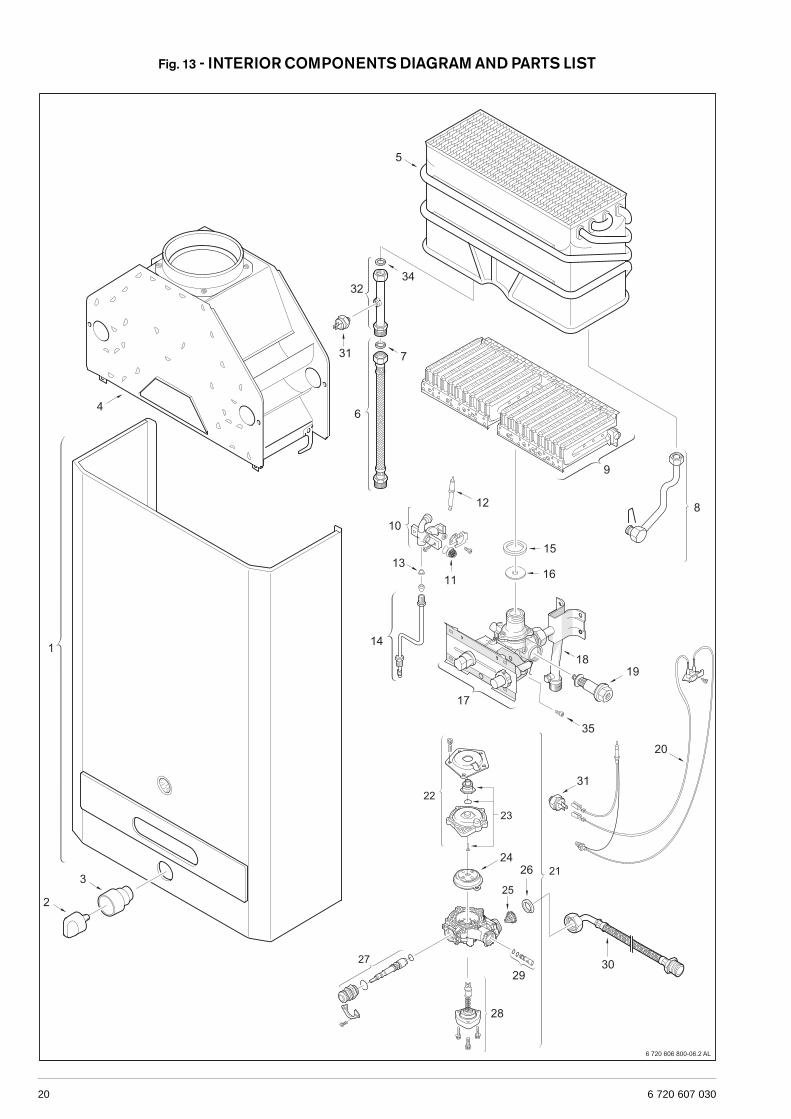
Fig. 13 - INTERIOR COMPONENTS DIAGRAM AND PARTS LIST
216 720 607 030
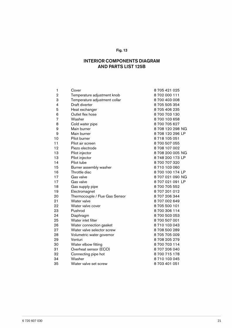
Fig. 13
INTERIOR COMPONENTS DIAGRAMAND PARTS LIST 125B
1 Cover 8 705 421 0252 Temperature adjustment knob 8 702 000 1113 Temperature adjustment collar 8 700 403 0084 Draft diverter 8 705 505 3545 Heat exchanger 8 705 406 2356 Outlet flex hose 8 700 703 1307 Washer 8 700 103 6588 Cold water pipe 8 700 705 6279 Main burner 8 708 120 298 NG9 Main burner 8 708 120 296 LP
10 Pilot burner 8 718 105 05111 Pilot air screen 8 700 507 05512 Piezo electrode 8 708 107 00213 Pilot injector 8 708 200 005 NG13 Pilot injector 8 748 200 173 LP14 Pilot tube 8 700 707 32015 Burner assembly washer 8 710 103 06016 Throttle disc 8 700 100 174 LP17 Gas valve 8 707 021 090 NG17 Gas valve 8 707 021 091 LP18 Gas supply pipe 8 700 705 55219 Electromagnet 8 707 201 01220 Thermocouple / Flue Gas Sensor 8 707 206 34421 Water valve 8 707 002 64922 Water valve cover 8 705 500 10123 Pushrod 8 700 306 11424 Diaphragm 8 700 503 05325 Water inlet filter 8 700 507 00126 Water connection gasket 8 710 103 04327 Water valve selector screw 8 708 500 28928 Volumetric water governor 8 705 705 00929 Venturi 8 708 205 27930 Water elbow fitting 8 700 703 11431 Overheat sensor (ECO) 8 707 206 04032 Connecting pipe hot 8 700 715 17834 Washer 8 710 103 04535 Water valve set screw 8 703 401 051
22 6 720 607 030
LIMITED WARRANTY
AquastarGeneralAquastar water heaters are warranted by the Manufacturer(BOSCH) through BBT North America. BBT North America(BBTNA) will furnish a replacement heat exchanger and willfurnish a replacement of any other part which fails in normaluse and service within the applicable periods specifiedbelow, in accordance with the terms of this warranty. TheBBTNA replacement will be warranted for the unexpiredportion of the original warranty. This warranty will be validonly for water heaters in possession of the original purchaseras recorded on the warranty card.
The heat exchangerIf the heat exchanger fails within twelve (12) years after theoriginal installation and operation BBTNA will furnish areplacement heat exchanger. However, if the water heateris installed in other than a single family dwelling this heatexchanger warranty is limited to two (2) years from date oforiginal installation and operation.
ExceptionsThis warranty will not apply:1. to defects or malfunctions resulting from failure to properly
install, operate or maintain the unit in accordance withthe printed instructions provided;
2. to damage or abuse, accident, neglect or freezing andother acts of nature;
3. to damage resulting from operation with either the flamesensor rod or overheat sensor removed;
4. to failure of the heat exchanger resulting from theoperation of the water heater in a corrosive atmosphereor at water temperatures exceeding the maximum rating,or if the water heater is not supplied with potable water;
5. to defects or damage cause by any attachmentor modification, including any energy-saving device.
All other partsIf any other part fails within two (2) years after originalinstallation and operation, BBTNA will furnish a replacementpart free of charge.
Shipping costsIn addition to supplying the replacement part(s), BBTNAwill provide ground service delivery for these parts. Expeditedor upgraded shipping will be charged to the customer.
Service labor costsThis warranty does not cover any labor costs associatedwith service, removal or re-installation of part(s). All suchcosts must be borne by the Purchaser. Additionally, thiswarranty does not cover any labor costs associated withservice, removal or re-installation of the original water heateror a replaced water heater.
How to Make a ClaimAny claim for warranty parts should be made to your localdealer, distributor or to BBTNA. If BBTNA, please contactthe Technical Support Department:
BBT NORTH AMERICA340 Mad River ParkWaitsfield, VT 05673Phone: 800-642-3111www.boschhotwater.com
In most cases, the dealer or distributor will be able to promptlyhonor your claim and subsequently notify BBTNA. However,all replacements are made subject to validation by BBTNAof in-warranty coverage. The damaged or defective item mustbe made available in exchange for the replacement.
MiscellaneousNo one is authorized to make any other warranties on behalfof BBTNA. It is expressly understood that the replacementwarranty of BBTNA shall be in lieu of any and all otherwarranties, express or implied, including warranties ofmerchantability or fitness for a particular use or purpose,and further that BBTNA shall not be liable for any loss ordamage directly or indirectly arising from the use of the hotwater heater, or for any consequential damages arising fromsuch use (including damages from water leakage). BBTNAsole liability with respect to any defect shall be for thereplacement of the defective part(s). Some states do notallow such limitations and exclusions, so the above may notapply to you.This warranty gives specific legal rights. You may also haveother rights which vary from state to state.
236 720 607 030
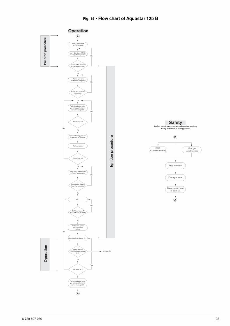
Fig. 14 - Flow chart of Aquastar 125 B

Recycled paper
41&31segapeesELBATECNANETNIAM
RAEYYREVE SRAEY2YREVE SRAEY5-3YREVE
EVLAVRETAWETACIRBUL †
EVLAVRETAWDLIUBER †
NEERCSRETLIFRETAWTCEPSNI †
YLBMESSATOLIPTCEPSNI †
YLBMESSATNEVTCEPSNI †
RENRUBNIAMTCEPSNI †
� 2005 BBT NORTH AMERICA,Waitsfield, VT all rights reserved
VULCANO Termodomésticos S.A.Estrada de Cacia
3801 - 856 Aveiro - PORTUGAL
Replacement Parts available from:
BBT NORTH AMERICABosch Group
Bosch Water Heating340 Mad River ParkWaitsfield, VT 05673Phone 800-642-3111Fax (802) [email protected]