apra users manual - perfectflite home page manual.pdfpo box 29 andover, nh 03216 url: voice (603)...
TRANSCRIPT

APRA Users Manual

PO Box 29Andover, NH 03216 URL: www.perfectflite.comVoice (603) 735-5994 Sales: [email protected] (603) 735-5221 Support: [email protected]
APRA Users Manual
A miniature, high accuracy altimeter for rocketry.
Contents
Introduction................................................................................................. 1Parts Identification Diagram.............................................................. 2Installation
Payload Bay Construction........................................................................................... 3Static Pressure Sampling Ports................................................................................. 5
OperationInstalling Battery............................................................................................................ 6Power Switches............................................................................................................... 6Numerical Reporting..................................................................................................... 7Powerup Sequence........................................................................................................ 8Tips for Achieving Optimal Accuracy..................................................................... 9Testing............................................................................................................................... 11Cautions............................................................................................................................ 11
Specifications............................................................................................ 12Warranty.................................................................................... Back Cover
1
Introduction
The APRA (Affordable Precision Rocket Altimeter) is a high-quality rocket altimeter that doesn’t sacrifice accuracy despiteits low price. It is extremely easy to use, yet provides the samephenomenal accuracy as our more expensive full featuredaltimeters. It is ideal for introductory rocket education, sciencefair data collection, and contest use.
The APRA is installed inside your rocket and activated prior tolaunch. When you retrieve your rocket, the APRA will reportthe apogee altitude (how high your rocket went, up to 100,000feet above ground) and the maximum velocity (how fast yourrocket went, in miles per hour). It uses a convenient, easy tounderstand audio reporting method that is audible fromoutside your rocket, so removal or inspection of the altimeteris not necessary. The reported altitude and velocity arealternated with a 10 second siren sound that helps to locateyour rocket even if it is hidden in tall grass or a tree.
If you need additional features, you may want to consider thePerfectFlite Pnut, which is smaller than the APRA, has a built-inrechargeable battery, and stores complete flight data (altitude,temperature, and battery voltage) from your last 31 flights.The data can be downloaded to a computer for storage,graphing, and additional manipulation. Or for even moreversatility, the PerfectFlite StratoLogger combines this flightdata download feature with two event electronic parachutedeployment for advanced users. Electronic deploymentprovides the ultimate in control over when your parachute isejected – no more guessing about which ejection delay lengthto use, the altimeter will always fire precisely at apogee.
2
The APRA utilizes a precision pressure sensor and 24 bit deltasigma analog to digital converter to obtain an extremelyaccurate measurement of the air pressure surrounding yourrocket. When turned on, the altimeter “tracks” the ambientpressure surrounding your rocket to get an up-to-the-secondreading of the barometric pressure at ground level. As therocket rises, the pressure decreases, and the altimeter convertsthe pressure differential to a precise measurement of altitudeabove launch point according to the US Standard Atmospheremodel. All of the calculations are done inside the altimeter,with the results reported simply as “altitude above groundlevel”. No conversion or adjustment is necessary.
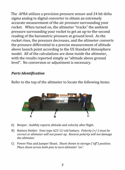
Parts Identification
Refer to the top of the altimeter to locate the following items:
A) Beeper: Audibly reports altitude and velocity after flight.
B) Battery Holder: Uses type A23 12 volt battery. Polarity (+/-) must becorrect or altimeter will not power up. Reverse polarity will not damagethe altimeter.
C) Power Pins and Jumper Shunt. Shunt shown in storage (“off”) position.Place shunt across both pins to turn altimeter “on”.

3
InstallationFor best results, your altimeter should be installed in aseparate payload compartment, sealed from the pressure andheat of the ejection charge gasses. While other alternatives arepossible, isolating the altimeter in a protected compartmentwill provide the most precise readings and will keep hightemperature and pressure from affecting the long-termaccuracy of the instrument.
A typical payload compartment consists of a section of bodytube behind the nosecone with a sealed tube couplerconnecting it to the main body tube (see illustration below).Some rockets (e.g. Estes “Nova Payloader”, Quest “Zenith II”)already have such a payload section, and one can be addedeasily if yours does not. Use pieces of foam rubber in front ofand behind the altimeter to prevent it from shifting underacceleration and deceleration and to protect it in the event of acrash. The altimeter will slide into 18mm/BT20 size bodytubes, and a “sleeve” made out of standard foam pipeinsulation can be used for larger size tubes. Your payloadsection should close securely so that the altimeter is not
“ejected” upon motor burnout deceleration or chutedeployment shock.
Perform initial testing of your rocket without the altimeterinstalled. Make sure that the parachute is ejected and opensproperly so that you have a slow and safe landing. If you

4
conduct your preliminary tests with the altimeter installed andthe chute doesn’t eject, the resulting high speed ballisticdescent will likely damage the altimeter (and your rocket!).
Note: If you have any doubt about the possibility of thishappening, protect the altimeter by wrapping a couple of wrapsof electrical tape end to end around the battery holder. This willprovide some protection to the battery holder from the relativelyheavy battery in the event of an abrupt landing.
When installing the APRA in larger rockets it may be easier toadd a short (~3” long) section of BT20 tube with padded endplugs for the altimeter to ride in. The short BT20 tube could beglued to the inside of the larger airframe or to a plywoodmounting plate. A static pressure sampling hole can be drilledthrough the main airframe and into the inner tube to allowexternal air pressure to get to the altimeter.
As a last resort, if accuracy isn’t of paramount importance, youcan simply tie the altimeter to the rocket’s shock cord and packit in along with the chute. If you must do this, observe thefollowing precautions:1. Use plenty of wadding between the ejection charge and the
parachute.
2. Position the parachute between the wadding and the altimeterto provide additional protection from the hot ejection chargegasses.
3. Make sure the altimeter is securely tied to the shock cord sothat it doesn’t separate and free-fall.
4. Add a wrap of tape around the battery and jumper shunt sothey don’t get dislodged at ejection. Note: Make sure the tapedoesn’t cover the pressure sensor (small white rectangle marked
“U3”) on the bottom of the altimeter.
5
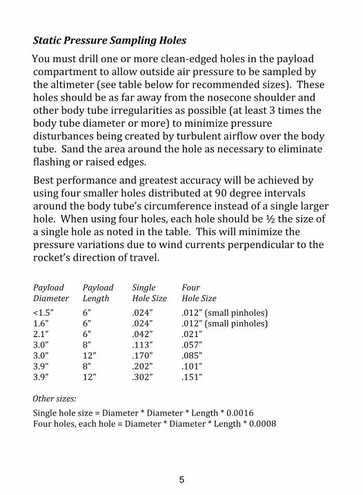
Static Pressure Sampling Holes
You must drill one or more clean-edged holes in the payloadcompartment to allow outside air pressure to be sampled bythe altimeter (see table below for recommended sizes). Theseholes should be as far away from the nosecone shoulder andother body tube irregularities as possible (at least 3 times thebody tube diameter or more) to minimize pressuredisturbances being created by turbulent airflow over the bodytube. Sand the area around the hole as necessary to eliminateflashing or raised edges.
Best performance and greatest accuracy will be achieved byusing four smaller holes distributed at 90 degree intervalsaround the body tube’s circumference instead of a single largerhole. When using four holes, each hole should be ½ the size ofa single hole as noted in the table. This will minimize thepressure variations due to wind currents perpendicular to therocket’s direction of travel.
Payload Payload Single FourDiameter Length Hole Size Hole Size<1.5” 6” .024” .012” (small pinholes)1.6” 6” .024” .012” (small pinholes)2.1” 6” .042” .021”3.0” 8” .113” .057”3.0” 12” .170” .085”3.9” 8” .202” .101”3.9” 12” .302” .151”
Other sizes:Single hole size = Diameter * Diameter * Length * 0.0016Four holes, each hole = Diameter * Diameter * Length * 0.0008
6
OperationBattery
The altimeter is powered by a standard 12 volt “A23” size remotebattery. Appropriate part numbers are Duracell MN21/23, GPA23, Energizer A23, and Radio Shack 23-144. Do not use a 1.5volt “N” cell, it won’t work. Observe polarity when installing thebattery – a backwards battery will not damage the altimeter, butthe altimeter won’t turn on.
Exercise care when installing and removing the battery toprolong the life of the battery holder: To install the battery, holdthe altimeter in one hand and the battery in the other hand.Press the “-” end of the battery against the battery holder’s spring,and swing the battery down into place. To remove the battery,use a fingernail or small screwdriver and press on the “+” end ofthe battery to slightly depress the spring. Raise the “+” end of thebattery up and out of the holder and the battery will pop out.
Power Switch
The jumper shunt shown in the picture on page 2 is used to turnthe altimeter on and off. Install the jumper shunt across the twopins on the altimeter’s circuit board to turn the altimeter on, andremove the shunt to turn it off. When the altimeter is not in use,you can place the jumper shunt on just one of the pins for storage.Make sure you use the shunt to turn the altimeter on and off – donot remove and insert the battery to provide the on/off function.Using the shunt instead will reduce wear and tear on the batteryholder.
For added convenience, you can use the optional power switchcable to connect an externally-accessible on/off switch to thealtimeter. The cable plugs onto the two pins on the circuit boardin place of the jumper shunt, and your switch is connected to theloose ends of the cable.

7
Numerical Reporting
Numbers are reported as a long beep (separator), followed by apattern of shorter beeps for the individual digits, with a pausebefore the next digit. You simply count the number of shortbeeps for each digit place and assemble them together to form anumber. You will hear a series of beeps for the first digit (tens ofthousands of feet), a short pause, another series of beeps for thenext digit (thousands of feet), etc.
Leading zeroes are suppressed: 1,582 feet would be representedwith four digits as in 1582, not five digits as in 01582.
Ten beeps are used to indicate the number zero (if zero beepswere used, you would not be able to differentiate between 2200feet and 22 feet!).
As an example, 12,560’ would be reported as:
long beep-pause-beep-pause-beep-beep-pause-beep-beep-beep-beep-beep-pause- beep-beep-beep-beep-beep-beep-pause-beep-beep-beep-beep-beep-beep- beep-beep-beep-beep-long pause
Digit Reported as:
0 beep-beep-beep-beep-beep-beep-beep-beep-beep-beep1 beep2 beep-beep3 beep-beep-beep4 beep-beep-beep-beep5 beep-beep-beep-beep-beep6 beep-beep-beep-beep-beep-beep7 beep-beep-beep-beep-beep-beep-beep8 beep-beep-beep-beep-beep-beep-beep-beep9 beep-beep-beep-beep-beep-beep-beep-beep-beep
8
Powerup
When the altimeter is turned on, it will report the peak altitudefrom the last flight and the current battery voltage beforereadying itself for flight. This is what you will hear:
• A three to six digit number (range of 160 feet to 103,500feet) representing the apogee altitude of the last flight.Note: A warbling siren tone will sound instead of the lastflight altitude if power was lost during the last flight.This error will clear after the next good flight.
• A two second pause, and then a two or three digit numberrepresenting the battery voltage in tenths of a volt (e.g.12.2 volts would report as 122).
• A thirty second pause (giving you time to close up therocket after turning the altimeter on), and then a periodic
“chirp” approximately once per second when the altimeter isready to launch.
While sounding the launch ready “chirp”, the altimeter willbegin tracking ground level pressure, and will continuouslyupdate its internal ground reading to follow fluctuations inground level pressure until time of launch.
The altimeter is ready to launch at this point.Do not launch before the periodic “chirp” is heard or thealtimeter will not function properly!
After flight the altimeter will report in this sequence:• An extra-long tone to indicate the start of the reporting
sequence.

9
• A three to six digit number representing the peak altitudein feet.
• A long separator tone followed by a two to five digitnumber representing the maximum velocity during theflight in miles per hour. This number, and its precedingseparator, are reported in a higher pitch to differentiate itfrom the peak altitude number.
• A pause of 5 seconds, and then a 10 second warbling sirentone to aid in locating the rocket if it is hidden from sight ina tree, tall grass, etc.
• After a 10 second period of silence, the sequence repeatsuntil power is disconnected. The flight’s peak altitude ispreserved when power is turned off, and will be reportedevery time power is turned on until a new flight is made.
Tips for Achieving Best Accuracy
• Use four static sampling ports instead of just one. Makesure they are sized and positioned according to theinstructions in the previous section. All barometricaltimeters base their altitude measurements on the airpressure surrounding the rocket, so getting a clean,turbulence-free sample is essential. A single hole,especially if it is over-sized, will introduce pressurefluctuations whenever the rocket deviates from its normaltrajectory. Four evenly-spaced holes will minimize thiseffect.
• With a properly designed rocket and motor combination,the parachute should eject at apogee (peak altitude), whenthe rocket is nearly stationary. This will guarantee aminimum of turbulent airflow around the rocket, and hencethe cleanest, most accurate data. If you eject your
10
parachute substantially before apogee, the rocket will stillbe traveling at a high rate of speed, which will degrade theaccuracy of any possible measurements due to the massivefluctuations in pressure. In addition, deploying the chutewhile the rocket is traveling at high speed can potentiallydamage your rocket due to a zippered body tube, strippedchute, or broken shock cord.
Ejecting at apogee is best, slightly after apogee is OK, butnever before apogee if you can avoid it. Ejecting beforeapogee will always guarantee a loss in potential altitude. Itwill also introduce significant degradation in altituderepeatability since the final altitude will then bedetermined by the (in)consistency of the motor’s ejectiondelay.
• Use a long shock cord. This will allow the ejected payloadsection and nose cone to slow gradually rather then beingjerked to a stop when the cord comes to full extension.Again, minimizing abrupt changes in the rocket’s trajectorywill result in the smoothest, most accurate data.

11
Testing
A simple apparatus for testing the altimeter can be made with asmall jar and a length of plastic hose. Drill a hole in the centerof the jar’s lid and insert one end of the plastic hose. Glue hosein place to achieve a tight seal (hot melt glue works well).
Turn on the altimeter and place it in the jar. Tighten the lid andwait until you can hear the periodic beep from the altimeterindicating launch readiness. Suck on the free end of the plastichose to create a vacuum within the jar. The altimeter willsense this as a launch condition and the beeping will stop.When you stop sucking on the hose, the altimeter will senseapogee as the pressure stabilizes. Open the hose and allow airto bleed back into the jar and the altimeter will sense descent.The altimeter will then beep out the “altitude” that yourvacuum was able to create within the jar.
Cautions
• Do not touch circuit board traces or components or allowmetallic objects to touch them when the altimeter ispowered on. This could cause damage to your altimeter.
• Provide adequate padding fore and aft of the altimeter forprotection in the event of a crash or excessively hardlanding.
• Do not allow the altimeter to get wet. Only operate thealtimeter within the environmental limits listed in thespecifications section.
• Do not rupture pressure sensor diaphragm with excessivepressure or sharp object.
12
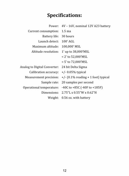
Specifications:
Power: 4V – 16V, nominal 12V A23 battery Current consumption: 1.5 ma Battery life: 30 hours Launch detect: 100’ AGL Maximum altitude: 100,000’ MSL Altitude resolution: 1’ up to 38,000’MSL < 2’ to 52,000’MSL < 5’ to 72,000’MSL Analog to Digital Converter: 24 bit Delta Sigma Calibration accuracy: +/- 0.05% typical Measurement precision: +/- (0.1% reading + 1 foot) typical Sample rate: 20 samples per second Operational temperature: -40C to +85C (-40F to +185F) Dimensions: 2.75”L x 0.55”W x 0.62”H Weight: 0.56 oz. with battery

Warranty
All PerfectFlite products include a full three year/36 monthwarranty against defects in parts and workmanship. Shouldyour PerfectFlite product fail during this period, call or emailour Customer Service department for information aboutreturning your product. The warranty applies to the altimeteronly, and does not cover the rocket, motor, or other equipment.This warranty does not cover damage due to misuse, abuse,alteration, or operation outside of the recommended operatingconditions included with your product. Broken pressuresensor diaphragms due to puncture or exposure to ejectioncharge pressure/hot gasses are NOT covered under thiswarranty.
Liability
Due care has been employed in the design and construction ofthis product so as to minimize the dangers inherent in its use.As the installation, setup, preparation, maintenance, and use ofthis equipment is beyond the control of the manufacturer, thepurchaser and user accept sole responsibility for the safe andproper use of this product. The principals, employees, andvendors of the manufacturer shall not be held liable for anydamage or claims resulting from any application of thisproduct. If the purchaser and user are not confident in theirability to use the product in a safe manner it should bereturned to the point of purchase immediately. Any use of thisproduct signifies acceptance of the above terms by thepurchaser and user.