applied gas dynamics basic facts - homepage | wiley¬nition of gas dynamics gas dynamics is e...
TRANSCRIPT
Applied Gas Dynamics
Basic Facts
Ethirajan Rathakrishnan
Applied Gas Dynamics, John Wiley & Sons (Asia) Pte Ltd c© 2010 Ethirajan Rathakrishnan 1 / 214

Definition of Gas Dynamics
Gas dynamics is e science of fluid flow in which both density and tem-perature changes become significant. Taking 5 percent change in tem-perature as significant, it can be stated that, at standard sea level, Machnumber 0.5 is the lower limit of gas dynamics. Thus, gas dynamics isthe science of flow fields with speeds Mach 0.5 and above. Therefore,gas dynamic regimes consist of both subsonic and supersonic Machnumbers. Further, when the flow is supersonic, any change of flowproperty or direction is caused by waves.
Applied Gas Dynamics, John Wiley & Sons (Asia) Pte Ltd c© 2010 Ethirajan Rathakrishnan 2 / 214
These waves are isentropic and nonisentropic compression waves (shockwaves), expansion waves and Mach waves. Among these, the com-pression and expansion waves can cause finite changes but the flowproperty changes caused by a Mach wave are insignificant. The essenceof gas dynamics is that, when the flow speed is supersonic, the entireflow field is dominated by Mach waves, expansion waves and shockwaves. It is through these waves, the change of flow properties fromone state to another takes place.
Applied Gas Dynamics, John Wiley & Sons (Asia) Pte Ltd c© 2010 Ethirajan Rathakrishnan 3 / 214

Introduction
Compressible flow is the science of fluid flow where the density changeassociated with pressure change is significant. Fluid mechanics is thescience of fluid flow in which the temperature changes associated withthe flow are insignificant. Fluid mechanics is essentially the science ofisenthalpic flows and thus the main equations governing a fluid dynamicstream are only the continuity and momentum equations and the sec-ond law of thermodynamics. The energy equation is passive as for asfluid dynamic streams are concerned.
Applied Gas Dynamics, John Wiley & Sons (Asia) Pte Ltd c© 2010 Ethirajan Rathakrishnan 4 / 214
At standard sea level conditions, considering less than five percentchange in temperature as insignificant, flow with Mach number less than0.5 can be termed as a fluid mechanic stream. A fluid mechanic streammay be compressible or incompressible. For an incompressible flowboth temperature and density changes are insignificant. For a com-pressible flow, the temperature change may be insignificant but densitychange is finite.
Applied Gas Dynamics, John Wiley & Sons (Asia) Pte Ltd c© 2010 Ethirajan Rathakrishnan 5 / 214

But in many engineering applications, such as design of airplane, mis-siles and launch vehicles, the flow Mach numbers associated are morethan 0.5. Hence both temperature and density changes associated withthe flow become significant. Study of such flows where both density andtemperature changes associated with pressure change become appre-ciable is called gas dynamics.
Applied Gas Dynamics, John Wiley & Sons (Asia) Pte Ltd c© 2010 Ethirajan Rathakrishnan 6 / 214

In other words, gas dynamics is the science of fluid flow in which bothdensity and temperature changes become significant. The essence ofgas dynamics is that the entire flow field is dominated by Mach waves,expansion waves and shock waves, when the flow speed issupersonic. It is through these waves, the change of flow propertiesfrom one state to another takes place.
Applied Gas Dynamics, John Wiley & Sons (Asia) Pte Ltd c© 2010 Ethirajan Rathakrishnan 7 / 214

In the theory of gas dynamics, change of state in flow properties isachieved by three means; (a) with area change, treating the fluid to beinviscid and passage to be frictionless, (b) with friction, treating theheat transfer between the surroundings and system to be negligibleand (c) with heat transfer, assuming the fluid to be inviscid. Thesethree types of flows are called isentropic flow, frictional or Fanno typeflow and Rayleigh type flow, respectively.
Applied Gas Dynamics, John Wiley & Sons (Asia) Pte Ltd c© 2010 Ethirajan Rathakrishnan 8 / 214
All problems in gas dynamics can be classified under the three flow pro-cesses described above, of course with the assumptions mentioned. Al-though it is impossible to have a flow process which is purely isentropicor Fanno type or Rayleigh type, in practice, it is justified in assuming so,since the results obtained with these treatments prove to be accurateenough for most practical problems in gas dynamics.
Applied Gas Dynamics, John Wiley & Sons (Asia) Pte Ltd c© 2010 Ethirajan Rathakrishnan 9 / 214

Compressibility
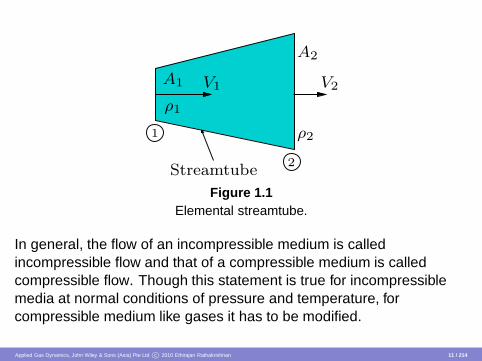
Fluids such as water are incompressible at normal conditions. Butunder conditions of high pressure (e.g. 1000 atmospheres) they arecompressible. The change in volume is the characteristic feature of acompressible medium under static condition. Under dynamicconditions, i.e. when the medium is moving, the characteristic featurefor incompressible and compressible flow situations are: the volumeflow rate, Q = AV = constant at any cross-section of a streamtube forincompressible flow and the mass flow rate, m = ρAV = constant atany cross-section of a streamtube for compressible flow. In theserelations, A is the cross-sectional area of the streamtube, V and ρ arerespectively the velocity and density of the fluid at that cross-section(Figure 1.1).
Applied Gas Dynamics, John Wiley & Sons (Asia) Pte Ltd c© 2010 Ethirajan Rathakrishnan 10 / 214
Streamtube2
V2
ρ21
V1
A2
ρ1
A1
Figure 1.1Elemental streamtube.
In general, the flow of an incompressible medium is calledincompressible flow and that of a compressible medium is calledcompressible flow. Though this statement is true for incompressiblemedia at normal conditions of pressure and temperature, forcompressible medium like gases it has to be modified.
Applied Gas Dynamics, John Wiley & Sons (Asia) Pte Ltd c© 2010 Ethirajan Rathakrishnan 11 / 214

As long as a gas flows at a sufficiently low speed from one cross-sectionto another of a passage the change in volume (or density) can be ne-glected and, therefore, the flow can be treated as incompressible. Al-though the fluid is compressible, this property may be neglected whenthe flow is taking place at low speeds. In other words, although thereis some density change associated with every physical flow, it is oftenpossible (for low speed flows) to neglect it and idealize the flow as in-compressible. This approximation is applicable to many practical flowsituations, such as low-speed flow around an airplane and flow througha vacuum cleaner.
Applied Gas Dynamics, John Wiley & Sons (Asia) Pte Ltd c© 2010 Ethirajan Rathakrishnan 12 / 214

From the above discussion it is clear that compressibility is the phe-nomenon by virtue of which the flow changes its density with changein speed. Now, we may question what are the precise conditions underwhich density changes must be considered? We will try to answer thisquestion now.
A quantitative measure of compressibility is the volume modulus of elas-ticity E , defined as
E = − ∆p∆V/Vi
(1.1)
where ∆p is the change in static pressure, ∆V is the change in volumeand Vi is the initial volume. For ideal gases, the equation of state is
pV = RT
Applied Gas Dynamics, John Wiley & Sons (Asia) Pte Ltd c© 2010 Ethirajan Rathakrishnan 13 / 214
For isothermal flows this reduces to
pV = p iVi = constant
where pi is the initial pressure.
The above equation may be written as
(pi + ∆p)(Vi + ´V) = p iVi
Expanding this equation and neglecting the second order terms, we get
∆pVi + ´Vp i = 0
Applied Gas Dynamics, John Wiley & Sons (Asia) Pte Ltd c© 2010 Ethirajan Rathakrishnan 14 / 214

Therefore,
∆p = −pi∆VVi
(1.2)
For gases, from Eqs. (1.1) and (1.2), we get
E = pi (1.3)
Hence, by Eq. (1.2), the compressibility may be defined as the volumemodulus of the pressure.
Applied Gas Dynamics, John Wiley & Sons (Asia) Pte Ltd c© 2010 Ethirajan Rathakrishnan 15 / 214

Limiting Conditions for Compressibility
By mass conservation, we have m = ρV = constant, where m is massflow rate per unit area, V is the flow velocity and ρ is the correspondingdensity. This can also be written as
(Vi + ∆V )(ρi + ∆ρ) = ρi Vi
Considering only first order terms, this simplifies to
∆ρ
ρi= − ∆V
Vi
Applied Gas Dynamics, John Wiley & Sons (Asia) Pte Ltd c© 2010 Ethirajan Rathakrishnan 16 / 214
Substituting this in to Eq. (1.1) and noting that V = V for unit area perunit time in the present case, we get
∆p = E∆ρ
ρi(1.4)
From Eq. (1.4), it is seen that the compressibility may also be definedas the density modulus of the pressure.
Applied Gas Dynamics, John Wiley & Sons (Asia) Pte Ltd c© 2010 Ethirajan Rathakrishnan 17 / 214
For incompressible flows, by Bernoulli’s equation, we have
p +12
ρ V 2 = constant = pstag
where the subscript “stag” refers to stagnation condition. The aboveequation may also be written as
pstag − p = ∆p =12
ρV 2
Applied Gas Dynamics, John Wiley & Sons (Asia) Pte Ltd c© 2010 Ethirajan Rathakrishnan 18 / 214

i.e., the change of pressure from stagnation to static states is equal to12 ρV 2. Using Eq. (1.4) in the above relation, we obtain
∆pE
=∆ρ
ρi=
ρiV 2i
2E=
qi
E(1.5)
where qi = 12ρiV 2
i is the dynamic pressure. Equation (1.5) relates thedensity change with flow speed.
Applied Gas Dynamics, John Wiley & Sons (Asia) Pte Ltd c© 2010 Ethirajan Rathakrishnan 19 / 214

The compressibility effects can be neglected if the density changes arevery small, i.e. if
∆ρ
ρi≪ 1
From Eq. (1.5) it is seen that, for neglecting compressibility
q/E ≪ 1
For gases, the speed of sound “a” may be expressed in terms of pres-sure and density changes as [see Eq. (1.11)]
a2 =∆p∆ρ
Applied Gas Dynamics, John Wiley & Sons (Asia) Pte Ltd c© 2010 Ethirajan Rathakrishnan 20 / 214
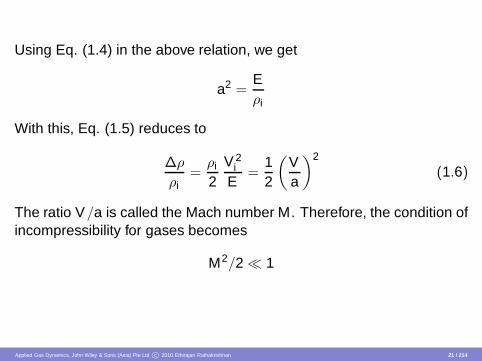
Using Eq. (1.4) in the above relation, we get
a2 =Eρi
With this, Eq. (1.5) reduces to
∆ρ
ρi=
ρi
2V 2
i
E=
12
(
Va
)2
(1.6)
The ratio V/a is called the Mach number M. Therefore, the condition ofincompressibility for gases becomes
M2/2 ≪ 1
Applied Gas Dynamics, John Wiley & Sons (Asia) Pte Ltd c© 2010 Ethirajan Rathakrishnan 21 / 214

Thus, the criterion determining the effect of compressibility for gases isthat the magnitude of the mach number M should be negligibly small.In deed, mathematics would stipulate this limit as M → 0. But for Machnumber zero corresponds to stagnation state. Therefore, in engineer-ing sciences flows with very small Mach number are treated as incom-pressible. To have a quantification of this limiting value of Mach numberto treat a flow as incompressible, Mach number corresponding to 5%change in flow density is usually taken as the limit.
Applied Gas Dynamics, John Wiley & Sons (Asia) Pte Ltd c© 2010 Ethirajan Rathakrishnan 22 / 214

It is widely accepted that compressibility can be neglected when
∆ρ
ρi≤ 0.05 or 5%
i.e. when M ≤ 0.3. In other words, the flow may be treated as incom-pressible when V ≤ 100 m/s, i.e., when V ≤ 360 kmph under standardsea level conditions. The above values of M and V are widely acceptedvalues and they may be re-fixed at different levels, depending upon theflow situation and the degree of accuracy desired.
Applied Gas Dynamics, John Wiley & Sons (Asia) Pte Ltd c© 2010 Ethirajan Rathakrishnan 23 / 214
Supersonic Flow - What is It?
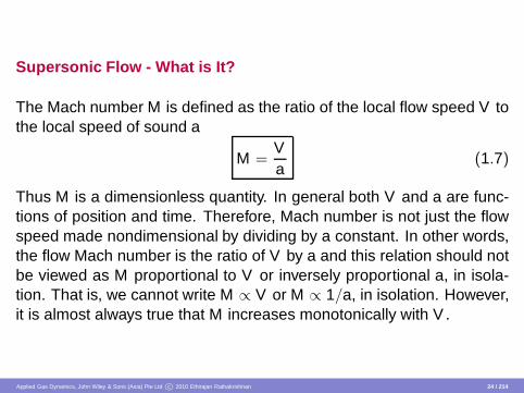
The Mach number M is defined as the ratio of the local flow speed V tothe local speed of sound a
M =Va
(1.7)
Thus M is a dimensionless quantity. In general both V and a are func-tions of position and time. Therefore, Mach number is not just the flowspeed made nondimensional by dividing by a constant. In other words,the flow Mach number is the ratio of V by a and this relation should notbe viewed as M proportional to V or inversely proportional a, in isola-tion. That is, we cannot write M ∝ V or M ∝ 1/a, in isolation. However,it is almost always true that M increases monotonically with V .
Applied Gas Dynamics, John Wiley & Sons (Asia) Pte Ltd c© 2010 Ethirajan Rathakrishnan 24 / 214

A flow with Mach number is greater than unity is termed supersonicflow. In a supersonic flow V > a and the flow upstream of a given pointremains unaffected by changes in conditions at that point.
Applied Gas Dynamics, John Wiley & Sons (Asia) Pte Ltd c© 2010 Ethirajan Rathakrishnan 25 / 214

Speed of Sound
Sound waves are infinitely small pressure disturbances. The speedwith which sound propagates in a medium is called speed of soundand is denoted by a. If an infinitesimal disturbance is created by thepiston, as shown in Figure 1.2, the wave propagates through the gas atthe velocity of sound relative to the gas into which the disturbance ismoving. Let the stationary gas at pressure pi and density ρi in the pipebe set in motion by moving the piston.
Applied Gas Dynamics, John Wiley & Sons (Asia) Pte Ltd c© 2010 Ethirajan Rathakrishnan 26 / 214

The infinitesimal pressure wave created by piston movement travelswith speed a, leaving the medium behind it at pressure p1 and densityρ1 to move with velocity V .
pi
V
Pipe of cross-sectionalarea A
p1
p1
Piston Pressurewave
ρ1
b
ρi
pi
a∆p
Figure 1.2Propagation of pressure disturbance.
Applied Gas Dynamics, John Wiley & Sons (Asia) Pte Ltd c© 2010 Ethirajan Rathakrishnan 27 / 214

As a result of compression created by the piston, the pressure and den-sity next to the piston are infinitesimally greater than the pressure anddensity of the gas at rest ahead of the wave. Therefore,
∆p = p1 − pi , ∆ρ = ρ1 − ρi
are small.Choose a control volume of length b, as shown in Figure 1.2. Com-pression of volume Ab causes the density to rise from ρi to ρ1 in timet = b/a. The mass flow into volume Ab is
m = ρ1AV (1.8)
Applied Gas Dynamics, John Wiley & Sons (Asia) Pte Ltd c© 2010 Ethirajan Rathakrishnan 28 / 214
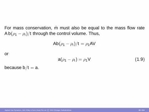
For mass conservation, m must also be equal to the mass flow rateA b(ρ1 − ρi)/t through the control volume. Thus,
Ab(ρ1 − ρi)/t = ρ1AV
ora(ρ1 − ρi) = ρ1V (1.9)
because b/t = a.
Applied Gas Dynamics, John Wiley & Sons (Asia) Pte Ltd c© 2010 Ethirajan Rathakrishnan 29 / 214

The compression wave caused by the piston motion travels and accel-erates the gas from zero velocity to V . The acceleration is given by
Vt
= Vab
The mass in the control volume Ab is
m = Abρ
whereρ =
ρi + ρ1
2
Applied Gas Dynamics, John Wiley & Sons (Asia) Pte Ltd c© 2010 Ethirajan Rathakrishnan 30 / 214

The force acting on the control volume is F = A(p1 − pi). Therefore, byNewton’s law,
A(p1 − pi) = m(
Vab
)
A(p1 − pi) = (Abρ)(
Vab
)
orρVa = p1 − pi (1.10)
Applied Gas Dynamics, John Wiley & Sons (Asia) Pte Ltd c© 2010 Ethirajan Rathakrishnan 31 / 214
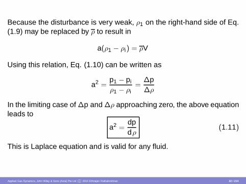
Because the disturbance is very weak, ρ1 on the right-hand side of Eq.(1.9) may be replaced by ρ to result in
a(ρ1 − ρi) = ρV
Using this relation, Eq. (1.10) can be written as
a2 =p1 − pi
ρ1 − ρi=
∆p∆ρ
In the limiting case of ∆p and ∆ρ approaching zero, the above equationleads to
a2 =dpdρ
(1.11)
This is Laplace equation and is valid for any fluid.
Applied Gas Dynamics, John Wiley & Sons (Asia) Pte Ltd c© 2010 Ethirajan Rathakrishnan 32 / 214
The sound wave is an isentropic pressure wave, across which only in-finitesimal change in fluid properties occur. Further, the wave itself isextremely thin and changes in properties occur very rapidly. The rapid-ity of the process rules out the possibility of any heat transfer betweenthe system of fluid particles and its surrounding.
For very strong pressure waves, the traveling speed of disturbance maybe greater than that of sound. The pressure can be expressed as
p = p(ρ) (1.12)
Applied Gas Dynamics, John Wiley & Sons (Asia) Pte Ltd c© 2010 Ethirajan Rathakrishnan 33 / 214

For isentropic process of a gas,
pργ
= constant
where the isentropic index γ is the ratio of specific heats and is a con-stant for a perfect gas. Using the above relation in Eq. (1.11), we get
a2 = γp/ρ (1.13)
For a perfect gas, by the state equation
p = ρRT (1.14)
where R is the gas constant and T the static temperature of the gas inabsolute units.
Applied Gas Dynamics, John Wiley & Sons (Asia) Pte Ltd c© 2010 Ethirajan Rathakrishnan 34 / 214
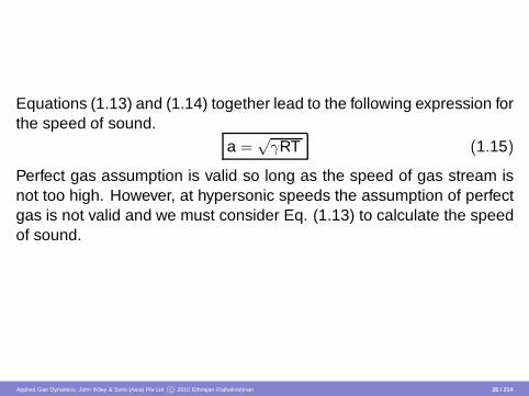
Equations (1.13) and (1.14) together lead to the following expression forthe speed of sound.
a =√
γRT (1.15)
Perfect gas assumption is valid so long as the speed of gas stream isnot too high. However, at hypersonic speeds the assumption of perfectgas is not valid and we must consider Eq. (1.13) to calculate the speedof sound.
Applied Gas Dynamics, John Wiley & Sons (Asia) Pte Ltd c© 2010 Ethirajan Rathakrishnan 35 / 214

Temperature Rise
For a perfect gas,
p = ρRT , R = cp − cv
where cp and cv are specific heats at constant pressure and constantvolume, respectively. Also, γ = cp/cv , therefore,
R =γ − 1
γcp (1.16)
For an isentropic change of state, an equation not involving T can bewritten as
p/ργ = constant
Applied Gas Dynamics, John Wiley & Sons (Asia) Pte Ltd c© 2010 Ethirajan Rathakrishnan 36 / 214
Now, between state 1 and any other state the relation between the pres-sures and densities can be written as
(
pp1
)
=
(
ρ
ρ1
)γ
(1.17)
Combining Eqs. (1.17) and (1.14), we get
TT1
=
(
ρ
ρ1
)γ−1
=
(
pp1
)(γ−1)/γ
(1.18)
The above relations are very useful for gas dynamic studies. The tem-perature, density and pressure ratios in Eq. (1.18) can be expressed interms of the flow Mach number.
Applied Gas Dynamics, John Wiley & Sons (Asia) Pte Ltd c© 2010 Ethirajan Rathakrishnan 37 / 214

Let us examine the flow around a symmetrical body, as shown in Figure1.3.
∞
Stagnation point
0
Figure 1.3Flow around a symmetrical body.
In a compressible medium, there will be change in density and temper-ature at point 0. The temperature rise at the stagnation point can beobtained from the energy equation.
Applied Gas Dynamics, John Wiley & Sons (Asia) Pte Ltd c© 2010 Ethirajan Rathakrishnan 38 / 214

The energy equation for an isentropic flow is
h +V 2
2= constant (1.19)
where h is the enthalpy.Equating the energy at far upstream ∞ and the stagnation point 0, weget
h∞ +V 2∞
2= h0 +
V 20
2But V0 = 0, thus
h0 − h∞ =V 2∞
2
Applied Gas Dynamics, John Wiley & Sons (Asia) Pte Ltd c© 2010 Ethirajan Rathakrishnan 39 / 214

For a perfect gas h = cpT , therefore, from the above relation we obtain
cp(T0 − T∞) =V 2∞
2
i.e.
∆T = T0 − T∞ =V 2∞
2cp(1.20)
Applied Gas Dynamics, John Wiley & Sons (Asia) Pte Ltd c© 2010 Ethirajan Rathakrishnan 40 / 214

Combining Eqs. (1.15) and (1.16), we get
cp =1
γ − 1a2∞
T∞
Hence,
∆T =γ − 1
2T∞M2
∞(1.21)
i.e.,
T0 = T∞
1 +γ − 1
2M2
∞
(1.22)
Applied Gas Dynamics, John Wiley & Sons (Asia) Pte Ltd c© 2010 Ethirajan Rathakrishnan 41 / 214

For air, γ = 1.4, hence
T0 = T∞
1 + 0.2M2∞
(1.23)
where T0 is the temperature at the stagnation point on the body. Itis also referred to as total temperature. For example, the flow at thestagnation point 0 on the body shown in Figure 1.3, the flow will attainthe stagnation temperature.
Applied Gas Dynamics, John Wiley & Sons (Asia) Pte Ltd c© 2010 Ethirajan Rathakrishnan 42 / 214

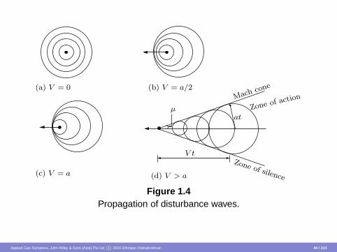
Mach Angle
The presence of a small disturbance is felt throughout the field by meansof disturbance waves traveling at the local velocity of sound relative tothe medium. Let us examine the propagation of pressure disturbancecreated by a moving object shown in Figure 1.4. The propagation ofdisturbance waves created by an object moving with velocity V = 0,V = a/2, V = a and V > a is shown in Figures 1.4(a), (b), (c), (d), re-spectively. In a subsonic flow the disturbance waves reach a stationaryobserver before the source of disturbance could reach him, as shownin Figures 1.4(a) and 1.4(b).
Applied Gas Dynamics, John Wiley & Sons (Asia) Pte Ltd c© 2010 Ethirajan Rathakrishnan 43 / 214
(d) V > a
V t
atµ
(a) V = 0Mach
cone
(c) V = a
(b) V = a/2
Zone of action
Zone of silence
Figure 1.4Propagation of disturbance waves.
Applied Gas Dynamics, John Wiley & Sons (Asia) Pte Ltd c© 2010 Ethirajan Rathakrishnan 44 / 214

But in supersonic flows it takes considerable amount of time for anobserver to perceive the pressure disturbance, after the source haspassed him. This is one of the fundamental differences between sub-sonic and supersonic flows. Therefore, in a subsonic flow the stream-lines sense the presence of any obstacle in the flow field and adjustthemselves well ahead of the obstacles and flow around it smoothly.But in a supersonic flow, the streamlines feel the obstacle only whenthey hit it. The obstacle acts as a source and the streamlines deviate atthe Mach cone as shown in Figure 1.4(d). That is in a supersonic flowthe disturbance due to an obstacle is sudden and the flow behind theobstacle has to change abruptly.
Applied Gas Dynamics, John Wiley & Sons (Asia) Pte Ltd c© 2010 Ethirajan Rathakrishnan 45 / 214

Flow around a wedge shown in Figures 1.5(a) and 1.5(b) illustrate thesmooth and abrupt change in flow direction for subsonic and supersonicflow, respectively. For M∞ < 1, the flow direction changes smoothlyand the pressure decreases with acceleration. For M∞ > 1, there is asudden change in flow direction at the body and the pressure increasesdownstream of the shock.
Shoc
k
(b) Supersonic flow(a) Subsonic flow
M∞ < 1 M∞ > 1
Figure 1.5Flow around a wedge.
Applied Gas Dynamics, John Wiley & Sons (Asia) Pte Ltd c© 2010 Ethirajan Rathakrishnan 46 / 214

In Figure 1.4(d), it is shown that for supersonic motion of an object thereis a well-defined conical zone in the flow field with the object located atthe nose of the cone and the disturbance created by the moving objectis confined only to the field included inside the cone. The flow field zoneoutside the cone does not even feel the disturbance. For this reason,von Karman termed the region inside the cone as the zone of actionand the region outside the cone as the zone of silence.
Applied Gas Dynamics, John Wiley & Sons (Asia) Pte Ltd c© 2010 Ethirajan Rathakrishnan 47 / 214
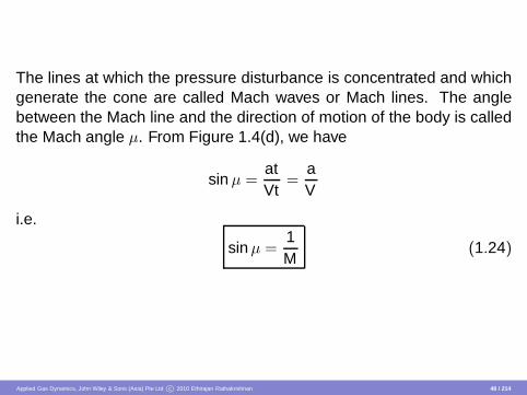
The lines at which the pressure disturbance is concentrated and whichgenerate the cone are called Mach waves or Mach lines. The anglebetween the Mach line and the direction of motion of the body is calledthe Mach angle µ. From Figure 1.4(d), we have
sin µ =atVt
=aV
i.e.
sin µ =1M
(1.24)
Applied Gas Dynamics, John Wiley & Sons (Asia) Pte Ltd c© 2010 Ethirajan Rathakrishnan 48 / 214

From the disturbance waves propagation shown in Figure 1.4, we caninfer the following features of the flow regimes.
When the medium is incompressible (M = 0, Figure 1.4a) or whenthe speed of the moving disturbance is negligibly small comparedto the local sound speed, the pressure pulse created by the distur-bance spreads uniformly in all directions.
When the disturbance source moves with a subsonic speed (M <1, Figure 1.4b), the pressure disturbance is felt in all directionsand at all points in space (neglecting viscous dissipation), but thepressure pattern is no longer symmetrical.
Applied Gas Dynamics, John Wiley & Sons (Asia) Pte Ltd c© 2010 Ethirajan Rathakrishnan 49 / 214

For sonic velocity (M = 1, Figure 1.4c) the pressure pulse is atthe boundary between subsonic and supersonic flow and the wavefront is a plane.
For supersonic speeds (M > 1, Figure 1.4d) the disturbance wavepropagation phenomenon is totally different from those at subsonicspeeds. All the pressure disturbances are included in a cone whichhas the disturbance source at its apex and the effect of the distur-bance is not felt upstream of the disturbance source.
Applied Gas Dynamics, John Wiley & Sons (Asia) Pte Ltd c© 2010 Ethirajan Rathakrishnan 50 / 214

Small Disturbance
When the apex angle of wedge δ is vanishingly small the disturbanceswill be small and we can consider these disturbance waves to be identi-cal to sound pulses. In such a case, the deviation of streamlines will besmall and there will be infinitesimally small increase of pressure acrossthe Mach cone shown in Figure 1.6.
Mac
h wave
M∞ > 1µ
δ
Figure 1.6Mach cone.
Applied Gas Dynamics, John Wiley & Sons (Asia) Pte Ltd c© 2010 Ethirajan Rathakrishnan 51 / 214
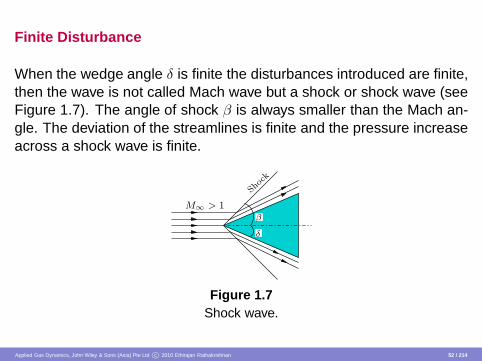
Finite Disturbance
When the wedge angle δ is finite the disturbances introduced are finite,then the wave is not called Mach wave but a shock or shock wave (seeFigure 1.7). The angle of shock β is always smaller than the Mach an-gle. The deviation of the streamlines is finite and the pressure increaseacross a shock wave is finite.
Shock
M∞ > 1β
δ
Figure 1.7Shock wave.
Applied Gas Dynamics, John Wiley & Sons (Asia) Pte Ltd c© 2010 Ethirajan Rathakrishnan 52 / 214

Thermodynamics of Fluid Flow
Entropy and temperature are the two fundamental concepts of ther-modynamics. Unlike low-speed or incompressible flows, the energychange associated with a compressible flow is substantial enough tostrongly interact with other properties of the flow. Hence the energyconcept plays an important role in the study of compressible flows. Inother words, the study of thermodynamics which deals with energy (andentropy) is an essential component in the study of compressible flow.
Applied Gas Dynamics, John Wiley & Sons (Asia) Pte Ltd c© 2010 Ethirajan Rathakrishnan 53 / 214

The following are the broad divisions of fluid flow based on thermo-dynamic considerations. (i) Fluid mechanics of perfect fluids, i.e., flu-ids without viscosity and heat (transfer) conductivity, is an extension ofequilibrium thermodynamics to moving fluids. The kinetic energy of thefluid has to be considered in addition to the internal energy which thefluid possesses even when at rest. (ii) Fluid mechanics of real fluids(goes beyond the scope of classical thermodynamics). The transportprocesses of momentum and heat (energy) are of primary interest here.But, even though thermodynamics is not fully and directly applicable toall phases of real fluid flow, it is often extremely helpful in relating theinitial and final conditions.
Applied Gas Dynamics, John Wiley & Sons (Asia) Pte Ltd c© 2010 Ethirajan Rathakrishnan 54 / 214

For low-speed flow problems, thermodynamic considerations are notneeded because the heat content of the fluid flow is so large comparedto the kinetic energy of the flow that the temperature remains nearlyconstant even if the whole kinetic energy is transformed into heat. Inother words, the difference between the static and stagnation tempera-tures is not significant in low-speed flows. But in high-speed flows, thekinetic energy content of the fluid can be so large compared to its heatcontent that the difference between the static and stagnation tempera-ture can become substantial. Hence, emphasis on the thermodynamicconcepts assumes importance in high-speed flow analysis.
Applied Gas Dynamics, John Wiley & Sons (Asia) Pte Ltd c© 2010 Ethirajan Rathakrishnan 55 / 214

First Law of Thermodynamics (Energy Equation)
Consider a closed system, consisting of a certain amount of gas at rest,across whose boundaries no transfer of mass is possible. Let δQ be anincremental amount of heat added to the system across the boundary(by thermal conduction or by direct radiation). Also, let δW denote thework done on the system by the surroundings (or by the system on thesurroundings). The sign convention is positive when the work is doneby the system and negative when the work is done on the system. Dueto the molecular motion of the gas, the system has an internal energyU. The first law of thermodynamics states that the heat added minuswork done by the system is equal to the change in the internal energyof the system, i.e.
δQ − δW = dU (1.25)
Applied Gas Dynamics, John Wiley & Sons (Asia) Pte Ltd c© 2010 Ethirajan Rathakrishnan 56 / 214
This is an empirical result confirmed by laboratory experiments andpractical experience. In Eq. (1.25), the internal energy U is a state vari-able (thermodynamic property). Hence, the change in internal energydU is an exact differential and its value depends only on the initial andfinal states of the system. In contrast (the non-thermodynamic proper-ties), δQ and δW depend on the process by which the system attainedits final state from the initial state.
Applied Gas Dynamics, John Wiley & Sons (Asia) Pte Ltd c© 2010 Ethirajan Rathakrishnan 57 / 214

In general, for any given dU, there are infinite number of ways (pro-cesses) by which heat can be added and work can be done on thesystem. In the present course of study, we will be mainly concernedwith the following three types of processes only.
1 Adiabatic process — a process in which no heat is added to ortaken away from the system.
2 Reversible process — a process which can be reversed withoutleaving any trace on the surroundings, i.e., both the system andthe surroundings are returned to their initial states at the end of thereverse process.
3 Isentropic process — a process which is adiabatic and reversible.
Applied Gas Dynamics, John Wiley & Sons (Asia) Pte Ltd c© 2010 Ethirajan Rathakrishnan 58 / 214

For an open system (e.g. pipe flow), there is always found a term (U +p V) present instead of just U. This term is referred to as enthalpy orheat function H given by
H = U + p V (1.26)
H2 − H1 = U2 − U1 + p2V2 − p1V1 (1.27)
where (p2V2 − p1V1) is termed flow work and subscripts 1 and 2 repre-sent states 1 and 2, respectively.
Applied Gas Dynamics, John Wiley & Sons (Asia) Pte Ltd c© 2010 Ethirajan Rathakrishnan 59 / 214

In general, we can say that the following are the major differences be-tween the open and closed systems.
1 The mass which enters or leaves an open system has kinetic en-ergy, whereas there is no mass transfer possible across the bound-aries of a closed system.
2 The mass can enter and leave an open system at different levelsof potential energy.
3 Open systems are capable of delivering work continuously, be-cause in the system the medium which transforms energy is contin-uously replaced. This useful work, which a machine continuouslydelivers, is called the shaft work.
Applied Gas Dynamics, John Wiley & Sons (Asia) Pte Ltd c© 2010 Ethirajan Rathakrishnan 60 / 214
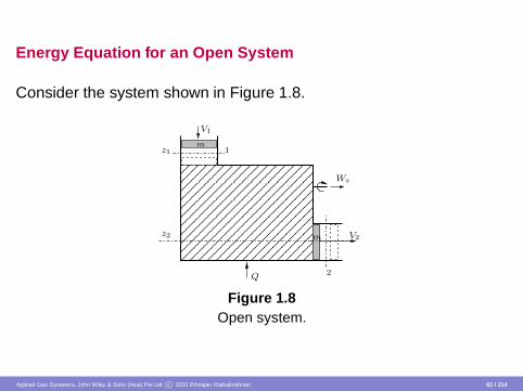
Energy Equation for an Open System
Consider the system shown in Figure 1.8.
������������������������������������������������
������������������������������������������������
Q
Ws
V2z2
V1
2
1z1
m
m
Figure 1.8Open system.
Applied Gas Dynamics, John Wiley & Sons (Asia) Pte Ltd c© 2010 Ethirajan Rathakrishnan 61 / 214

The total energy E at the inlet station 1 and the outlet station 2 is givenby
E1 = U1 +12
m V 21 + m g z1 (1.28)
E2 = U2 +12
m V 22 + m g z2 (1.29)
Applied Gas Dynamics, John Wiley & Sons (Asia) Pte Ltd c© 2010 Ethirajan Rathakrishnan 62 / 214

For an open system, the first-law expressions given by Eq. (1.25) hasto be rewritten with the total energy E in place of the internal energy U.Thus, we have
Q12 − W12 = E2 − E1 (1.30)
Substituting for E1 and E2 from Eqs. (1.28) and (1.29), respectively, weget
Q12 − W12 =
U2 +m2
V 22 + m g z2
−
U1 +m2
V 21 + m g z1
(1.31)
Applied Gas Dynamics, John Wiley & Sons (Asia) Pte Ltd c© 2010 Ethirajan Rathakrishnan 63 / 214
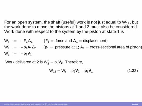
For an open system, the shaft (useful) work is not just equal to W12, butthe work done to move the pistons at 1 and 2 must also be considered.Work done with respect to the system by the piston at state 1 is
W′
1 = −F1∆1 (F1 = force and ∆1 = displacement)
W′
1 = −p1A1∆1 (p1 = pressure at 1; A1 = cross-sectional area of piston)
W′
1 = −p1V1
Work delivered at 2 is W′
2 = p2V2. Therefore,
W12 = Ws + p2V2 − p1V1 (1.32)
Applied Gas Dynamics, John Wiley & Sons (Asia) Pte Ltd c© 2010 Ethirajan Rathakrishnan 64 / 214

In Eq. (1.32), Ws is the shaft work, which can be extracted from thesystem and (p2V2 − p1V1) is the flow work necessary to maintain theflow. Substituting Eq. (1.32) into Eq. (1.31), we get
Q12 −Ws =
U2 + p2V2 +m2
V22 + m g z2
−
U1 + p1V1 +m2
V21 + m g z1
or
Q12 − Ws =
H2 +m2
V 22 + m g z2
−
H1 +m2
V 21 + m g z1
where H1 = U1 + p1V1 and H2 = U2 + p2V2. This is the fundamentalequation for an open system.
Applied Gas Dynamics, John Wiley & Sons (Asia) Pte Ltd c© 2010 Ethirajan Rathakrishnan 65 / 214
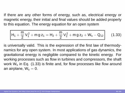
If there are any other forms of energy, such as, electrical energy ormagnetic energy, their initial and final values should be added properlyto this equation. The energy equation for an open system
H1 +m2
V 21 + m g z1 = H2 +
m2
V 22 + m g z2 + Ws − Q12 (1.33)
is universally valid. This is the expression of the first law of thermody-namics for any open system. In most applications of gas dynamics, thegravitational energy is negligible compared to the kinetic energy. Forworking processes such as flow in turbines and compressors, the shaftwork Ws in Eq. (1.33) is finite and, for flow processes like flow aroundan airplane, Ws = 0.
Applied Gas Dynamics, John Wiley & Sons (Asia) Pte Ltd c© 2010 Ethirajan Rathakrishnan 66 / 214

Therefore, for a gas dynamic working process, Eq. (1.33) becomes
H1 +m2
V 21 = H2 +
m2
V 22 + Ws − Q12 (1.34)
This is usually the case with turbo machines, internal combustion en-gines, etc., where the process is assumed to be adiabatic (i.e. Q12 = 0).For a gas dynamic adiabatic flow process, the energy equation (1.33)becomes
H1 +m2
V 21 = H2 +
m2
V 22 (1.35)
or
H1 +m2
V 21 = H0 = constant (1.36)
where H0 is the stagnation enthalpy and H1 is the static enthalpy. Thatis, the sum of static enthalpy and kinetic energy is constant in anadiabatic flow.
Applied Gas Dynamics, John Wiley & Sons (Asia) Pte Ltd c© 2010 Ethirajan Rathakrishnan 67 / 214

Adiabatic Flow Process
For an adiabatic process, the heat transfer associated with the process,Q = 0. Therefore, the energy equation is given by Eqs. (1.35) and(1.36). Dividing Eqs. (1.35) and (1.36) by m, we can rewrite them as
h1 +V 2
1
2= h2 +
V 22
2(1.37)
h1 +V 2
1
2= h0 (1.38)
Applied Gas Dynamics, John Wiley & Sons (Asia) Pte Ltd c© 2010 Ethirajan Rathakrishnan 68 / 214

or, in general,
h + V 2
2 = h0 = constant (1.39)
where h = H/m is called specific static enthalpy and h0 is the specificstagnation enthalpy. With h = p/ρ, Eq. (1.39) represents Bernoulli’sequation for incompressible flow,
p +12
ρ V 2 = p0 = constant
where p0 is the stagnation pressure. That is, for incompressible flow ofair the energy equation happens to be the Bernoulli equation, becausewe are not interested in the internal energy and the temperature forsuch flows.
Applied Gas Dynamics, John Wiley & Sons (Asia) Pte Ltd c© 2010 Ethirajan Rathakrishnan 69 / 214

In other words, Bernoulli’s equation is the limiting case of the energyequation for incompressible flows. Here it is important to realize thateven though Bernoulli’s equation for incompressible flow of a gas isshown to be the limiting case of energy equation, it is essentially amomentum equation. For a closed system,
Q12 − W12 = U2 − U1
In terms of specific quantities this becomes
q12 − w12 = u2 − u1
Applied Gas Dynamics, John Wiley & Sons (Asia) Pte Ltd c© 2010 Ethirajan Rathakrishnan 70 / 214

For the processes of a closed system there is no shaft work, i.e., nouseful work can be extracted from the working medium. There will onlybe compression or expansion work. Therefore, w12 may be expressedas
w12 =
∫ 2
1p dV
Thus, the change in internal energy becomes
du = δq − p dv (1.40a)
Also, h = u + pv ; dh = du + p dv + v dp. Using relation (1.40a), we canwrite the change in enthalpy as
dh = δq + v dp (1.40b)
Applied Gas Dynamics, John Wiley & Sons (Asia) Pte Ltd c© 2010 Ethirajan Rathakrishnan 71 / 214
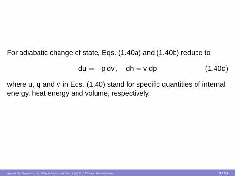
For adiabatic change of state, Eqs. (1.40a) and (1.40b) reduce to
du = −p dv , dh = v dp (1.40c)
where u, q and v in Eqs. (1.40) stand for specific quantities of internalenergy, heat energy and volume, respectively.
Applied Gas Dynamics, John Wiley & Sons (Asia) Pte Ltd c© 2010 Ethirajan Rathakrishnan 72 / 214
The Second Law of Thermodynamics (Entropy Equation)
Consider a cold body coming in to contact with a hot body. From experi-ence we can say that the cold body will get heated up and the hot bodywill cool down. However, Eq. (1.25) does not necessarily imply that thiswill happen. In fact, the first law allows the cold body to become coolerand the hot body to become hotter as long as energy is conserved dur-ing the process. However, in practice this does not happen; instead,the law of nature imposes another condition on the process, a conditionthat stipulates the direction in which a process should take place.
Applied Gas Dynamics, John Wiley & Sons (Asia) Pte Ltd c© 2010 Ethirajan Rathakrishnan 73 / 214
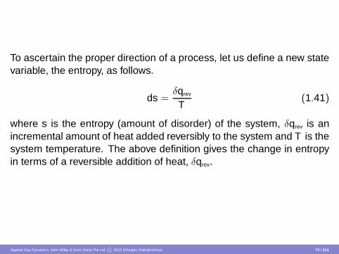
To ascertain the proper direction of a process, let us define a new statevariable, the entropy, as follows.
ds =δqrev
T(1.41)
where s is the entropy (amount of disorder) of the system, δqrev is anincremental amount of heat added reversibly to the system and T is thesystem temperature. The above definition gives the change in entropyin terms of a reversible addition of heat, δqrev.
Applied Gas Dynamics, John Wiley & Sons (Asia) Pte Ltd c© 2010 Ethirajan Rathakrishnan 74 / 214

Since entropy is a state variable, it can be used in conjunction withany type of process, reversible or irreversible. The quantity δqrev is justan artifice; an effective value of δqrev can always be assigned to relatethe initial and final states of an irreversible process, where the actualamount of heat added is δq. In deed, an alternative and probably morelucid relation is
ds =δqT
+ dsirrev (1.42)
Equation (1.42) applies in general to all processes.
Applied Gas Dynamics, John Wiley & Sons (Asia) Pte Ltd c© 2010 Ethirajan Rathakrishnan 75 / 214
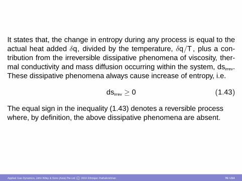
It states that, the change in entropy during any process is equal to theactual heat added δq, divided by the temperature, δq/T , plus a con-tribution from the irreversible dissipative phenomena of viscosity, ther-mal conductivity and mass diffusion occurring within the system, dsirrev.These dissipative phenomena always cause increase of entropy, i.e.
dsirrev ≥ 0 (1.43)
The equal sign in the inequality (1.43) denotes a reversible processwhere, by definition, the above dissipative phenomena are absent.
Applied Gas Dynamics, John Wiley & Sons (Asia) Pte Ltd c© 2010 Ethirajan Rathakrishnan 76 / 214

Hence, a combination of Eqs. (1.42) and (1.43) yields
ds ≥ δqT
(1.44)
Further, if the process is adiabatic, δq = 0 and Eq. (1.44) reduces to
ds ≥ 0 (1.45)
Equations (1.44) and (1.45) are two forms of the second law of thermo-dynamics.
Applied Gas Dynamics, John Wiley & Sons (Asia) Pte Ltd c© 2010 Ethirajan Rathakrishnan 77 / 214

The second law gives the direction in which a process will take place.Equations (1.44) and (1.45) imply that a process will always proceedin a direction such that the entropy of the system plus surroundings al-ways increases, or at least remains unchanged. That is, in an adiabaticprocess the entropy can never decrease. This aspect of the secondlaw of thermodynamics is important because it distinguishes betweenreversible and irreversible processes.
Applied Gas Dynamics, John Wiley & Sons (Asia) Pte Ltd c© 2010 Ethirajan Rathakrishnan 78 / 214

If ds > 0, the process is called an irreversible process and when ds = 0,the process is called a reversible process. A reversible and adiabaticprocess is called an isentropic process. However, in a non-adiabaticprocess, we can extract heat from the system and thus decrease theentropy of the system.
Applied Gas Dynamics, John Wiley & Sons (Asia) Pte Ltd c© 2010 Ethirajan Rathakrishnan 79 / 214

Thermal and Calorical Properties
The equation pv = RT or p/ρ = RT is called thermal equation of state,where p, T and v(= 1/ρ) are thermal properties and R is the gas con-stant. A gas which obeys the thermal equation of state is called ther-mally perfect gas. Any relation between the calorical properties, u, hand s and any two thermal properties is called calorical equation ofstate. In general, the thermodynamic properties (the properties whichdo not depend on process) can be grouped into thermal properties (p,T , v) and calorical properties (u, h, s).
Applied Gas Dynamics, John Wiley & Sons (Asia) Pte Ltd c© 2010 Ethirajan Rathakrishnan 80 / 214

From Eqs. (1.40), we have
u = u(T , v), h = h(T , p)
In terms of exact differentials, the above relations become
du =
(
∂u∂T
)
vdT +
(
∂u∂v
)
Tdv (1.46)
dh =
(
∂h∂T
)
pdT +
(
∂h∂p
)
Tdp (1.47)
Applied Gas Dynamics, John Wiley & Sons (Asia) Pte Ltd c© 2010 Ethirajan Rathakrishnan 81 / 214

For a constant volume process, Eq. (1.46) reduces to
du =
(
∂u∂T
)
vdT
where(
∂u∂T
)
v is the specific heat at constant volume represented as cv ,therefore,
du = cv dT (1.48)
For an isobaric process, Eq. (1.47) reduces to
dh =
(
∂h∂T
)
pdT
where(
∂h∂T
)
p is the specific heat at constant pressure represented bycp, therefore,
dh = cp dT (1.49)
Applied Gas Dynamics, John Wiley & Sons (Asia) Pte Ltd c© 2010 Ethirajan Rathakrishnan 82 / 214

From Eqs. (1.40a) for a constant volume (isochoric) process, we get
δq = du = cv dT (1.50a)
and for a constant pressure (isobaric) process,
δq = dh = cp dT , δq = dh = cv dT + p dv (1.50b)
For an adiabatic flow process (q = 0), from Eq. (1.40c) we have
dh = v dp (1.50c)
Applied Gas Dynamics, John Wiley & Sons (Asia) Pte Ltd c© 2010 Ethirajan Rathakrishnan 83 / 214

From Eqs. (1.50) it can be inferred that,
1 If heat is added at constant volume, it only raises the internal en-ergy.
2 If heat is added at constant pressure, it not only increases the in-ternal energy but also does some external work, i.e. it increasesthe enthalpy.
3 If the change is adiabatic, the change in enthalpy is equal to exter-nal work v dp.
Applied Gas Dynamics, John Wiley & Sons (Asia) Pte Ltd c© 2010 Ethirajan Rathakrishnan 84 / 214

Thermally Perfect Gas
A gas is said to be thermally perfect when its internal energy and en-thalpy are functions of temperature alone, i.e. for a thermally perfectgas,
u = u(T ), h = h(T ) (1.51a)
Therefore, from Eqs. (1.48) and (1.49), we get
cv = cv (T ), cp = cp(T ) (1.51b)
Further, from Eqs. (1.46), (1.47) and (1.51a), we obtain(
∂u∂v
)
T= 0,
(
∂h∂p
)
T= 0 (1.51c)
Applied Gas Dynamics, John Wiley & Sons (Asia) Pte Ltd c© 2010 Ethirajan Rathakrishnan 85 / 214

The important relations of this section are
du = cv dT , dh = cp dT
These equations are universally valid so long as the gas is thermallyperfect. Otherwise, in order to have equations of universal validity, we
must add(
∂u∂v
)
T dv to the first equation and(
∂h∂p
)
Tdp to the second
equation.
Applied Gas Dynamics, John Wiley & Sons (Asia) Pte Ltd c© 2010 Ethirajan Rathakrishnan 86 / 214

The state equation for a thermally perfect gas is,
pv = RT
In the differential form, this equation becomes
p dv + v dp = R dT
Also,
h = u + pv
dh = du + p dv + v dp
Applied Gas Dynamics, John Wiley & Sons (Asia) Pte Ltd c© 2010 Ethirajan Rathakrishnan 87 / 214

Therefore,dh − du = p dv + v dp = R dT
i.e.R dT = cp dT − cv dT
Thus,R = cp (T ) − cv (T ) (1.52)
For thermally perfect gases, Eq. (1.52) shows that, though cp and cv arefunctions of temperature, their difference is a constant with reference totemperature.
Applied Gas Dynamics, John Wiley & Sons (Asia) Pte Ltd c© 2010 Ethirajan Rathakrishnan 88 / 214

The Perfect Gas
This is a still more specialization than thermally perfect gas. For a per-fect gas, both cp and cv are constants and are independent of temper-ature, i.e.
cv = constant 6= cv (T ), cp = constant 6= cp(T ) (1.53)
Such a gas with constant cp and cv is called a calorically perfect gas.Therefore, a perfect gas should be thermally as well as calorically per-fect.
Applied Gas Dynamics, John Wiley & Sons (Asia) Pte Ltd c© 2010 Ethirajan Rathakrishnan 89 / 214

From the above discussions it is evident that,1 A perfect gas must be both thermally and calorically perfect.2 A perfect gas must satisfy both thermal equation of state; p = ρ R T
and caloric equations of state; cp = (∂h/∂T )p , cv = (∂u/∂T )v .
3 A calorically perfect gas must be thermally perfect and a thermallyperfect gas need not be calorically perfect. That is, thermal per-fectness is a prerequisite for caloric perfectness.
4 For a thermally perfect gas, cp = cp(T ) and cv = cv (T ); i.e. both cp
and cv are functions of temperature. But even though the specificheats cp and cv vary with temperature, their ratio, γ becomes aconstant and independent of temperature, i.e. γ = constant 6=γ(T ).
5 For a calorically perfect gas, cp, cv as well as γ are constants andindependent of temperature.
Applied Gas Dynamics, John Wiley & Sons (Asia) Pte Ltd c© 2010 Ethirajan Rathakrishnan 90 / 214

Entropy Calculation
Entropy is defined by the relation (for a reversible process)
δq = T ds
Using Eqs. (1.40), we can write
T ds = du + p dv (1.54)
T ds = dh − v dp (1.55)
Equations (1.54) and (1.55) are as important and useful as the originalform of the first law of thermodynamics, viz. Eq. (1.25).
Applied Gas Dynamics, John Wiley & Sons (Asia) Pte Ltd c© 2010 Ethirajan Rathakrishnan 91 / 214
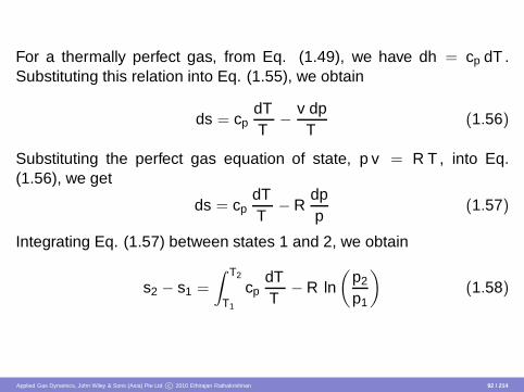
For a thermally perfect gas, from Eq. (1.49), we have dh = cp dT .Substituting this relation into Eq. (1.55), we obtain
ds = cpdTT
− v dpT
(1.56)
Substituting the perfect gas equation of state, p v = R T , into Eq.(1.56), we get
ds = cpdTT
− Rdpp
(1.57)
Integrating Eq. (1.57) between states 1 and 2, we obtain
s2 − s1 =
∫ T2
T1
cpdTT
− R ln(
p2
p1
)
(1.58)
Applied Gas Dynamics, John Wiley & Sons (Asia) Pte Ltd c© 2010 Ethirajan Rathakrishnan 92 / 214

Equation (1.58) holds for a thermally perfect gas. The integral can beevaluated if cp is known as a function of T . Further, assuming the gasto be calorically perfect, for which cp is constant, Eq. (1.58) reduces to
s2 − s1 = cp ln(
T2
T1
)
− R ln(
p2
p1
)
(1.59)
Using du = cv dT in Eq. (1.54), the change in entropy can also beexpressed as
s2 − s1 = cv ln(
T2
T1
)
+ R ln(
v2
v1
)
(1.60)
Applied Gas Dynamics, John Wiley & Sons (Asia) Pte Ltd c© 2010 Ethirajan Rathakrishnan 93 / 214

From the above discussion, we can summarize that a perfect gas isboth thermally and calorically perfect. Further, a calorically perfect gasmust also be thermally perfect, whereas a thermally perfect gas neednot be calorically perfect.
For a thermally perfect gas, p = ρRT , cv = cv (T ), cp = cp(T ) and fora perfect gas, p = ρRT , cv = constant cp = constant. Further, for aperfect gas all equations get simplified, resulting in the following simplerelations for u, h and s.
u = u1 + cv T (1.61a)
h = h1 + cp T (1.61b)
s = s1 + cv ln(
pp1
)
− cp ln(
ρ
ρ1
)
(1.61c)
where the subscript “1” refers to the initial state.
Applied Gas Dynamics, John Wiley & Sons (Asia) Pte Ltd c© 2010 Ethirajan Rathakrishnan 94 / 214

Equations (1.61a), (1.61b) and (1.52) combined with the thermal equa-tion of state (p = ρRT ) result in
u = u1 +1
γ − 1pρ, h = h1 +
γ
γ − 1pρ
where γ is the ratio of specific heats, cp/cv . For the most simple molec-ular model, the kinetic theory of gases gives the specific heats ratio, γas
γ =n + 2
n
where n is the number of degrees of freedom of the gas molecules.Thus, for monatomic gases with n = 3 (only 3 translational degrees offreedom), the specific heats ratio becomes
γ =3 + 2
3= 1.67
Applied Gas Dynamics, John Wiley & Sons (Asia) Pte Ltd c© 2010 Ethirajan Rathakrishnan 95 / 214
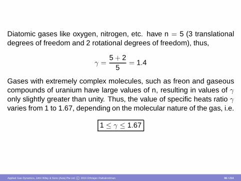
Diatomic gases like oxygen, nitrogen, etc. have n = 5 (3 translationaldegrees of freedom and 2 rotational degrees of freedom), thus,
γ =5 + 2
5= 1.4
Gases with extremely complex molecules, such as freon and gaseouscompounds of uranium have large values of n, resulting in values of γonly slightly greater than unity. Thus, the value of specific heats ratio γvaries from 1 to 1.67, depending on the molecular nature of the gas, i.e.
1 ≤ γ ≤ 1.67
Applied Gas Dynamics, John Wiley & Sons (Asia) Pte Ltd c© 2010 Ethirajan Rathakrishnan 96 / 214

The above relations for u and h are important, because they connect thequantities used in thermodynamics with those used in gas dynamics.With the aid of these relations, the energy equation can be written intwo different forms, as follows.
1 The energy equation for an adiabatic process, as given by Eq.(1.39), is
h +V 2
2= h0 = constant
when the gas is perfect, it becomes
cpT +V 2
2= cpT0 = constant (1.62a)
2 Equation (1.62a), when combined with the state equation, yields
γ
γ − 1pρ
+V 2
2= constant (1.62b)
Applied Gas Dynamics, John Wiley & Sons (Asia) Pte Ltd c© 2010 Ethirajan Rathakrishnan 97 / 214
Equation (1.62b) is the form of energy equation commonly used in gasdynamics. This is popularly known as compressible Bernoulli’s equationfor isentropic flows.
From Eq. (1.62a), we infer that for an adiabatic process of a perfect gas,
T01 = T02 = T0 = constant (1.63)
So far, we have not made any assumption about the reversibility orirreversibility of the process. Equation (1.63) implies that the stagnationtemperature T0 remains constant for an adiabatic process of a perfectgas, irrespective of the process being reversible or irreversible.
Applied Gas Dynamics, John Wiley & Sons (Asia) Pte Ltd c© 2010 Ethirajan Rathakrishnan 98 / 214

Consider the flow of gas in a tube with an orifice as shown in Figure1.9. In such a flow process, there will be pressure loss. But if thestagnation temperature is measured before and after the orifice plateand if it remains constant, then the gas can be treated as perfect gasand all the simplified equations (Eq. 1.61) can be used. Otherwise, itcannot be treated as perfect gas and Eq. (1.61c) can be rewritten as
p2
p1=
(
ρ2
ρ1
)γ
exp [(s2 − s1)/cv ] (1.64)
Orifice plate
Flow
Figure 1.9Flow through an orifice plate.
Applied Gas Dynamics, John Wiley & Sons (Asia) Pte Ltd c© 2010 Ethirajan Rathakrishnan 99 / 214

Isentropic Relations
An adiabatic and reversible process is called isentropic process. Foran adiabatic process, δq = 0 and for a reversible process, dsirrev = 0.Hence, from Eq. (1.42), an isentropic process is one for which ds =0, i.e., the entropy is constant. Important relations for an isentropicprocess can be directly obtained from Eqs. (1.59), (1.60) and (1.64) bysetting s2 = s1. For example, from Eq. (1.59) we have
0 = cp ln(
T2
T1
)
− R ln(
p2
p1
)
ln(
p2
p1
)
=cp
Rln
(
T2
T1
)
p2
p1=
(
T2
T1
)cp/R
(1.65)
Applied Gas Dynamics, John Wiley & Sons (Asia) Pte Ltd c© 2010 Ethirajan Rathakrishnan 100 / 214

From Eq. (1.52),
cp − cv = R
1 − cv
cp=
Rcp
γ − 1γ
=Rcp
since cp/cv = γ. Therefore,
cp
R=
γ
γ − 1
Substituting this relation into Eq. (1.65), we obtain
p2
p1=
(
T2
T1
)γ/(γ−1)
(1.66)
Applied Gas Dynamics, John Wiley & Sons (Asia) Pte Ltd c© 2010 Ethirajan Rathakrishnan 101 / 214

Similarly, from Eq. (1.60),
0 = cv ln(
T2
T1
)
+ R ln(
v2
v1
)
ln(
v2
v1
)
= −cv
Rln
(
T2
T1
)
v2
v1=
(
T2
T1
)
−cv /R
(1.67)
But it can be shown thatcv
R=
1γ − 1
Applied Gas Dynamics, John Wiley & Sons (Asia) Pte Ltd c© 2010 Ethirajan Rathakrishnan 102 / 214

Substituting the above relation into Eq. (1.67), we get
v2
v1=
(
T2
T1
)
−1/(γ−1)
(1.68)
Since ρ2/ρ1 = v1/v2, Eq. (1.68) becomes
ρ2
ρ1=
(
T2
T1
)1/(γ−1)
(1.69)
Applied Gas Dynamics, John Wiley & Sons (Asia) Pte Ltd c© 2010 Ethirajan Rathakrishnan 103 / 214

Substituting s1 = s2 into Eq. (1.64), we obtain
p2
p1=
(
ρ2
ρ1
)γ
(1.70)
This relation is also called Poisson’s equation. Summarizing Eqs. (1.66),(1.69) and (1.70), we can write
p2
p1=
(
ρ2
ρ1
)γ
=
(
T2
T1
)γ/(γ−1)
(1.71)
Equation (1.71) is an important equation and is used very frequently inthe analysis of compressible flows.
Applied Gas Dynamics, John Wiley & Sons (Asia) Pte Ltd c© 2010 Ethirajan Rathakrishnan 104 / 214

Using the above discussed isentropic relations, several useful equa-tions of total (stagnation) conditions can be obtained as follows. FromEqs. (1.15) and (1.62a),
T0
T= 1 +
V 2
2cpT= 1 +
V 2
2γ R T/(γ − 1)= 1 +
V 2
2a2/(γ − 1)
where T is the static temperature, T0 is the stagnation temperature andV is the flow velocity. Hence,
T0
T= 1 +
γ − 12
M2 (1.72)
Applied Gas Dynamics, John Wiley & Sons (Asia) Pte Ltd c© 2010 Ethirajan Rathakrishnan 105 / 214

Equation (1.72) gives the ratio of total to static temperature at a point inan isentropic flow field as a function of the flow Mach number M at thatpoint. Combining Eqs. (1.71) and (1.72), we get
p0
p=
(
1 +γ − 1
2M2
)γ/(γ−1)
(1.73)
ρ0
ρ=
(
1 +γ − 1
2M2
)1/(γ−1)
(1.74)
Equations (1.73) and (1.74) give the ratio of total to static pressure andtotal and static density, respectively, at a point in an isentropic flow fieldas a function of the flow Mach number M at that point.
Applied Gas Dynamics, John Wiley & Sons (Asia) Pte Ltd c© 2010 Ethirajan Rathakrishnan 106 / 214
Equations (1.72)-(1.74) form a set of most important equations for totalproperties, which are often used in gas dynamic studies. Their valuesas a function of M for γ = 1.4 (air at standard conditions) are tabulatedin Table 1 of appendix.
At this stage we may ask how Eq. (1.71), which is derived on the basisof the concept of isentropic change of state (which is so restrictive –adiabatic as well as reversible – that it may find only limited applications)is so important and why it is frequently used.
Applied Gas Dynamics, John Wiley & Sons (Asia) Pte Ltd c© 2010 Ethirajan Rathakrishnan 107 / 214

In compressible flow processes such as flow through a rocket engine,flow over an airfoil, etc., large regions of the flow fields are isentropic.In the region adjacent to the rocket nozzle walls and the airfoil surface,a boundary layer is formed wherein the dissipative mechanisms ofviscosity, thermal conduction and diffusion are strong. Hence, theentropy increases within these boundary layers. On the other hand, forfluid elements outside the boundary layer, the dissipative effects arenegligible.
Applied Gas Dynamics, John Wiley & Sons (Asia) Pte Ltd c© 2010 Ethirajan Rathakrishnan 108 / 214

Further, no heat is being added to or removed from the fluid elementat these points; hence the flow is adiabatic. Therefore, the fluid ele-ments outside the boundary layer experience reversible adiabatic pro-cess, hence the flow is isentropic. Moreover, the boundary layers areusually thin; hence large regime of flow fields are isentropic. Therefore,a study of isentropic flow is directly applicable to many types of practicalflow problems. Equation (1.71) is a powerful relation connecting pres-sure, density and temperature and is valid for calorically perfect gases.
Applied Gas Dynamics, John Wiley & Sons (Asia) Pte Ltd c© 2010 Ethirajan Rathakrishnan 109 / 214

Expressing all the quantities as stagnation quantities, Eq. (1.61c) canbe written as
s02 − s01 = cv ln(
p02
p01
)
− cp ln(
ρ02
ρ01
)
(1.75)
Also, by Eq. (1.52),R = cp − cv
and by the state equation
p01
p02=
ρ01
ρ02
T01
T02
Applied Gas Dynamics, John Wiley & Sons (Asia) Pte Ltd c© 2010 Ethirajan Rathakrishnan 110 / 214

Substitution of the above relations into Eq. (1.75) yields
s02 − s01 = R ln(
p01
p02
)
+ cp ln(
T02
T01
)
For an adiabatic process of a perfect gas,
T01 = T02
Therefore,
s02 − s01 = R ln(
p01
p02
)
(1.76)
Applied Gas Dynamics, John Wiley & Sons (Asia) Pte Ltd c© 2010 Ethirajan Rathakrishnan 111 / 214

From Eq. (1.76) it is obvious that the entropy changes only when thereare losses in pressure. It does not change with velocity and hence thereis nothing like static and stagnation entropy. Also, by Eq. (1.63), thestagnation temperature does not change even when there are pressurelosses. There is always an increase in entropy associated with pressureloss. In other words, when there are losses, there will be an increase inentropy, leading to a drop in stagnation pressure. These losses can bedue to friction, separation, shocks, etc.
Applied Gas Dynamics, John Wiley & Sons (Asia) Pte Ltd c© 2010 Ethirajan Rathakrishnan 112 / 214

Example 1.1
Argon is compressed adiabatically in a steady-flow compressor from101 kPa and 25◦C to 505 kPa. If the compression work required is 475kJ/kg, show that the compression process is irreversible. Assume argonto be an ideal gas.
Solution
As we know, the work required for a process is minimum when theprocess is isentropic, that is, when the process is adiabatic andreversible. Also, any process requiring more work than that requiredfor an isentropic process is irreversible.
Applied Gas Dynamics, John Wiley & Sons (Asia) Pte Ltd c© 2010 Ethirajan Rathakrishnan 113 / 214

For an isentropic process, work transfer can be expressed as
w12 =γ
γ − 1R T1
[
1 −(
p2
p1
)γ−1
γ
]
Given that,
T1 = 25◦C = 298.15 K, p1 = 101 kPa, p2 = 505 kPa
For argon, γ = 1.67 and R = 8314/39.944 = 208.14 J/(kg K), since themolecular weight of argon is 39.944.
Applied Gas Dynamics, John Wiley & Sons (Asia) Pte Ltd c© 2010 Ethirajan Rathakrishnan 114 / 214

Substituting these values into the work transfer equation, we get
w12 =1.67 × 208.14
0.67× 298.15
[
1 −(
505101
)0.671.67
]
= − 140.34 kJ/kg
The actual work required, 475 kJ/kg, is more than the isentropic worktransfer. Hence, the process is irreversible.
Applied Gas Dynamics, John Wiley & Sons (Asia) Pte Ltd c© 2010 Ethirajan Rathakrishnan 115 / 214

Example 1.2
The Mach number of an aircraft is the same at all altitudes. If its speedis 90 kmph slower at 7000 m altitude than at sea level, what is its Machnumber?
Solution
From standard atmospheric table, at 7000 m altitude, we get the localtemperature Th as
Th = 242.65 K
Therefore, the speed of sound at 7000 m altitude is
ah =√
γ R Th =√
1.4 × 287 × 242.65 = 312.24 m/s
At sea level,T0 = 15◦C = 288.15 K
Applied Gas Dynamics, John Wiley & Sons (Asia) Pte Ltd c© 2010 Ethirajan Rathakrishnan 116 / 214

The speed of sound at sea level is
a0 =√
γ R T0 =√
1.4 × 287 × 288.15 = 340.26 m/s
The Mach number is the same at these two altitudes. Thus,
V0
a0=
Vh
ah=
(
V0 − 903.6
)
ah
Applied Gas Dynamics, John Wiley & Sons (Asia) Pte Ltd c© 2010 Ethirajan Rathakrishnan 117 / 214

V0ah
a0= V0 −
903.6
V0
(
ah
a0− 1
)
= − 903.6
V0
(
312.24340.26
− 1)
= − 25
V0 = 303.59 m/s
M =V0
a0=
303.59340.26
= 0.892
Applied Gas Dynamics, John Wiley & Sons (Asia) Pte Ltd c© 2010 Ethirajan Rathakrishnan 118 / 214

Example 1.3
Air enters a compressor at a stagnation state of 100 kPa and 27◦C. Ifit has to be compressed to a stagnation pressure of 900 kPa, calculatethe power input to the compressor when the mass flow rate is 0.02 kg/s.Assume the compression process to be isentropic.
Solution Given that,
p01 = 100 kPa, T01 = 27◦C = 300 K, p02 = 900 kPa
Applied Gas Dynamics, John Wiley & Sons (Asia) Pte Ltd c© 2010 Ethirajan Rathakrishnan 119 / 214
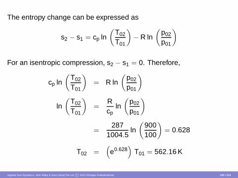
The entropy change can be expressed as
s2 − s1 = cp ln(
T02
T01
)
− R ln(
p02
p01
)
For an isentropic compression, s2 − s1 = 0. Therefore,
cp ln(
T02
T01
)
= R ln(
p02
p01
)
ln(
T02
T01
)
=Rcp
ln(
p02
p01
)
=287
1004.5ln
(
900100
)
= 0.628
T02 =(
e0.628)
T01 = 562.16 K
Applied Gas Dynamics, John Wiley & Sons (Asia) Pte Ltd c© 2010 Ethirajan Rathakrishnan 120 / 214

The power required is
Power = m ∆h = m cp (T02 − T01)
= 0.02 × 1004.5 × (562.16 − 300)
= 5.27 kW
Applied Gas Dynamics, John Wiley & Sons (Asia) Pte Ltd c© 2010 Ethirajan Rathakrishnan 121 / 214
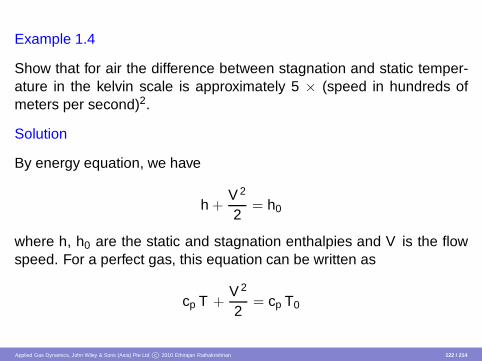
Example 1.4
Show that for air the difference between stagnation and static temper-ature in the kelvin scale is approximately 5 × (speed in hundreds ofmeters per second)2.
Solution
By energy equation, we have
h +V 2
2= h0
where h, h0 are the static and stagnation enthalpies and V is the flowspeed. For a perfect gas, this equation can be written as
cp T +V 2
2= cp T0
Applied Gas Dynamics, John Wiley & Sons (Asia) Pte Ltd c© 2010 Ethirajan Rathakrishnan 122 / 214

Therefore, the stagnation temperature-rise is
T0 − T =V 2
2 cp=
(γ − 1) V 2
2 γ R
since, cp = γγ−1R.
For air, R = 287 J/(kg K) and γ = 1.4, under normal temperatures. Sub-stituting for R and γ in the above equation, we get
T0 − T =0.4
2 × 1.4 × 287V 2
= 4.9776 × 10⁻⁴ V 2 K
≈ 5(
V × 10− 2)2
K
≈ 5 (speed in hundreds of meters per second)2
Applied Gas Dynamics, John Wiley & Sons (Asia) Pte Ltd c© 2010 Ethirajan Rathakrishnan 123 / 214

Limitations on Air as a Perfect Gas
1 When the temperature is less than 500 K, air can be treated as aperfect gas and the ratio of specific heats, γ takes a constant valueof 1.4.
2 When the temperature lies between 500 K and 2000 K, air is onlythermally perfect (but calorically imperfect) and the state equationp = ρ R T is valid, but cp and cv become functions of temperature,cp = cp(T ) and cv = cv (T ). Even though cp and cv are functions oftemperature, their ratio γ continues to be independent of temper-ature. That is, cp and cv vary with temperature in such a mannerthat their ratio continues to be the same constant as in tempera-tures below 500 K.
3 For temperatures more than 2000 K, air becomes both thermallyand calorically imperfect. That is, cp, cv as well as γ become func-tions of temperature.
Applied Gas Dynamics, John Wiley & Sons (Asia) Pte Ltd c© 2010 Ethirajan Rathakrishnan 124 / 214

In supersonic flight with Mach number, say 2.0 at sea level, the tem-perature reached is already about 245◦ C (more than 500 K). But, for500 K ≤ T ≤ 700 K, we can still use perfect gas equations and the errorinvolved in doing so will be negligible, i.e., for Mach number less than2.68, perfect gas equations can be used with slight error. For tempera-tures more than 700 K, we must go for thermally perfect gas equations.
Applied Gas Dynamics, John Wiley & Sons (Asia) Pte Ltd c© 2010 Ethirajan Rathakrishnan 125 / 214
At this stage, we may have some doubt about the possible values of theisentropic index γ, when the flow medium is at a temperature which isquite high and the medium cannot be assumed as perfect. This doubtcan be cleared if we consider the flow medium as an ideal gas, whichsatisfies perfect gas equations, has γ = constant, independent of tem-perature. For a monatomic gas (such as He, Ar, Ne, etc.), the simplestpossible molecular structure gives γ = 5/3. This prediction is well con-firmed by experiment.
Applied Gas Dynamics, John Wiley & Sons (Asia) Pte Ltd c© 2010 Ethirajan Rathakrishnan 126 / 214

At the other extreme of molecular complexity, very complicated moleculeshave large number of degrees of freedom and γ may approach unity,which represents the minimum possible value, since cp ≥ cv by virtueof a general thermodynamic argument (Refer E. Rathakrishnan, Fun-damentals of Engineering Thermodynamics, 2nd ed. 2005). Then γnecessarily has a range of values
53≥ γ ≥ 1
Experimental results show that most diatomic gases, nitrogen and oxy-gen in particular, have γ = 7/5 at room temperature, gradually tendingto γ = 9/7 at a few thousand kelvin.
Applied Gas Dynamics, John Wiley & Sons (Asia) Pte Ltd c© 2010 Ethirajan Rathakrishnan 127 / 214

Wave Propagation
We studied that in incompressible flows the fluid particles could ableto sense the presence of a body before actually reaching it. This factsuggests that a signaling mechanism exists, whereby the fluid particlescan be informed, in advance, about the presence of a body ahead ofit. The velocity of propagation of this signal must be apparently greaterthan the fluid velocity, since the flow is able to adjust to the presence ofa body before reaching it. On the other hand, if the fluid particles wereto move faster than the signal waves as in the case of supersonic flows,the fluid would not be able to sense the body before actually reaching itand abrupt changes in velocity and other properties would take place.
Applied Gas Dynamics, John Wiley & Sons (Asia) Pte Ltd c© 2010 Ethirajan Rathakrishnan 128 / 214

An understanding of the mechanism by which the signal waves arepropagating through fluid medium along with an expression for the ve-locity of propagation of the waves will be extremely useful in deriv-ing significant conclusions concerning the fundamental differences be-tween incompressible and compressible flows.
When a fluid medium is allowed to vary its density, the consequence isthat the fluid elements could able to occupy varying volumes in space.This possibility means that a set of fluid elements can spread into alarger region of space without requiring a simultaneous shift to bemade to all fluid elements in the flow field, as would be required in thecase of incompressible flow, in order to keep the density constant.
Applied Gas Dynamics, John Wiley & Sons (Asia) Pte Ltd c© 2010 Ethirajan Rathakrishnan 129 / 214
From studies on physics, we know that a small shift of fluid elements incompressible media will induce in due course similar small movementsin adjacent elements and in this way a disturbance, referred to as anacoustic wave, propagates at a relatively high speed through themedium. Furthermore, in incompressible flows these waves propagatewith infinitely large velocity; in other words, adjustments take placeinstantaneously throughout the flow and so in the conventional sense,there are no acoustic or elastic waves to be considered. With theintroduction of compressibility, we thus permit the possibility of elasticwaves having a finite velocity and the magnitude of this wave velocityis of great importance in compressible flow theory.
Applied Gas Dynamics, John Wiley & Sons (Asia) Pte Ltd c© 2010 Ethirajan Rathakrishnan 130 / 214

Velocity of Sound
Sound wave is a weak compression wave across which onlyinfinitesimal changes in flow properties occur, i.e. across these wavesthere will be only infinitesimal pressure variations. In the ensuingchapters, we shall study waves where comparatively large pressurevariation occurs over a very narrow front. Such waves are called shockwaves, the flow process across them is nonisentropic and moverelative to the fluid at speeds that exceed the speed of sound.
Applied Gas Dynamics, John Wiley & Sons (Asia) Pte Ltd c© 2010 Ethirajan Rathakrishnan 131 / 214
At this stage one may think of the sound waves as limiting cases ofshock waves where the change in pressure across the wave becomesinfinitesimal.
By Eq. (1.15), we have the speed of sound a as a =√
γRT , where Tis the static temperature of the medium in absolute unit. The speed ofsound in perfect gas may be computed by employing Eq. (1.15) and forthe other fluids by employing Eq. (1.11).
Applied Gas Dynamics, John Wiley & Sons (Asia) Pte Ltd c© 2010 Ethirajan Rathakrishnan 132 / 214
Subsonic and Supersonic Flows
The velocity of sound is used as the limiting value for differentiatingthe subsonic flow from the supersonic flow. Flows with velocity morethan the speed of sound are called supersonic flows and those withvelocities less than the speed of sound are called subsonic flows. Flowswith velocity close to the speed of sound are classified under a specialcategory called transonic flows.
Applied Gas Dynamics, John Wiley & Sons (Asia) Pte Ltd c© 2010 Ethirajan Rathakrishnan 133 / 214

We saw the propagation of disturbance waves in flow fields with ve-locities from zero level to a level greater than the speed of sound, andthat these disturbances will propagate along a “Mach cone”. For super-sonic flow over two-dimensional objects, we will have a “Mach wedge”instead of Mach cone. The angle µ for such waves is measured in acounter-clockwise manner from an axis taken parallel to the direction offreestream as shown in Figure 1.10.
Applied Gas Dynamics, John Wiley & Sons (Asia) Pte Ltd c© 2010 Ethirajan Rathakrishnan 134 / 214

yM > 1
+µ
−µ
Right-running wave
Disturbance Left-running wave
x
Figure 1.10Waves in supersonic flows.
For an observer looking in the direction of flow towards the disturbance,the wave to his left is called left-running wave and the wave to his right iscalled right-running wave (Figure 1.10). Usually, the disturbance arisesat a solid boundary where the fluid, having arrived supersonically with-out prior warning through pressure or sound signals, is made to un-dergo a change in direction, thus initiating a disturbance at the bound-ary which propagates along the Mach waves.
Applied Gas Dynamics, John Wiley & Sons (Asia) Pte Ltd c© 2010 Ethirajan Rathakrishnan 135 / 214

For historical interest, we should mention that Newton was the first tocalculate the propagation speed of pressure waves. Based on the as-sumed isothermal process in a perfect gas, he found the speed of prop-agation of sound to be equal to the square root of the ratio of the pres-sure to the corresponding density involved in the process, i.e.
a =√
p/ρ
Because the science of thermodynamics was not known at Newton’stime, the 18% difference between his theory and experiment was neverjustified.
Applied Gas Dynamics, John Wiley & Sons (Asia) Pte Ltd c© 2010 Ethirajan Rathakrishnan 136 / 214

Nearly a century later, Marquis de Laplace rectified Newton’s calcu-lation. The basic difference between Laplace’s theory and Newton’stheory is that the former considered an adiabatic process for propaga-tion of pressure waves. This is fully justified since the compressionstaking place in the propagation of pressure waves produce a very smalltemperature gradient and hence it is not possible for heat due to com-pression to be transferred to the surrounding region. The correction byLaplace from adiabatic process model multiplied Newton’s formula by√
γ. The correct expression for speed of sound is a =√
γRT , which isthe same as Eq. (1.15).
Applied Gas Dynamics, John Wiley & Sons (Asia) Pte Ltd c© 2010 Ethirajan Rathakrishnan 137 / 214
Similarity Parameters
In our discussions in the previous sections, we saw the Mach numberM as a primary parameter which dictates the flow pattern in the com-pressible regime of flow. In the chapters to follow, it will be seen thatM is also a parameter which appears almost in all equations of motion.Here the aim is to show that M is an important parameter for experi-mental studies too.
Let us consider a prototype and a model which are geometrically similar.Now, it is our interest to find the condition which must be met in orderto have the flow pattern around the model be similar to that around theprototype.
Applied Gas Dynamics, John Wiley & Sons (Asia) Pte Ltd c© 2010 Ethirajan Rathakrishnan 138 / 214

Examining the energy equation and taking into account the effect ofviscosity and heat conductivity, it can be shown that the specific heatsratio, γ, must be the same for both the model and prototype. Thus, itcan be concluded that the Mach number, M, must be the same for themodel and prototype, if the flows are to be similar. When viscosity ispresent, an analysis applied to the inertia and viscous terms in the mo-mentum equation leads to the criterion that the Reynolds number mustbe the same for ensuring similarity of flow pattern around the model andprototype.
Applied Gas Dynamics, John Wiley & Sons (Asia) Pte Ltd c© 2010 Ethirajan Rathakrishnan 139 / 214

Thus, by considering all the physical equations which govern the flow,namely, the continuity, momentum and energy equation and the equa-tions of state, it is possible to arrive at four dimensionless parameterswhich must be the same for dynamic similarity of the model and proto-type flow fields. They are
Applied Gas Dynamics, John Wiley & Sons (Asia) Pte Ltd c© 2010 Ethirajan Rathakrishnan 140 / 214

Mach number, M =Va
Reynolds number, ReL =ρVLµ
Ratio of specific heats, γ =cp
cv
Prandtl number, Pr =µcp
kwhere V is the flow velocity, a is speed of sound, ρ is the flow density,L is a characteristic dimension of the body in the flow, µ is the viscositycoefficient, cp is specific heat at constant pressure, cv is specific heatat constant volume and k is the thermal conductivity of the fluid.
Applied Gas Dynamics, John Wiley & Sons (Asia) Pte Ltd c© 2010 Ethirajan Rathakrishnan 141 / 214
In the potential flow region outside the boundary layer, where the vis-cous and heat conduction effects are relatively unimportant, it is usuallynecessary that only M and γ are to be the same between the modeland prototype flow fields to establish similarity. Of the two, similarity inM is more important than γ, since γ has a relatively weak influence onthe flow pattern.
Applied Gas Dynamics, John Wiley & Sons (Asia) Pte Ltd c© 2010 Ethirajan Rathakrishnan 142 / 214

Within the boundary layer, or in the interior of shock waves, viscous andheat conduction effects are significant. Hence, the Reynolds numberand Prandtl number also must be included in the similarity conditions.But the Prandtl number is nearly the same for all gases and varies onlyslowly with temperature.
Applied Gas Dynamics, John Wiley & Sons (Asia) Pte Ltd c© 2010 Ethirajan Rathakrishnan 143 / 214

Continuum Hypothesis
From kinetic theory of gases, we know that matter is made up of a largenumber of molecules which are in constant motion and collision. Butin the problems of engineering interest, we are concerned only withthe gross behavior of the fluid, thought of as a continuous material andnot in the motion of the individual molecules of the fluid. Even thoughthe postulation of continuous fluid (continuum) is only a convenient as-sumption, it is a valid approach to many practical problems where onlythe macroscopic or phenomenological information is of interest.
Applied Gas Dynamics, John Wiley & Sons (Asia) Pte Ltd c© 2010 Ethirajan Rathakrishnan 144 / 214

The assumption of fluids as continua is valid only when the smallestvolume of fluid of interest contains large number of molecules so thatthe statistical averages are meaningful. The advantage of continuumtreatment is that, instead of dealing with the instantaneous states oflarge number of molecules, we have to deal with only certain propertiesdescribing the gross behavior of the substance. In compressible flowsthe relevant properties are the density, pressure, temperature, velocity,shear stress, coefficient of viscosity, internal energy, entropy and coef-ficient of thermal conductivity. The macroscopic approach with contin-uum hypothesis will fail whenever the mean free path of the moleculesis of the same order of the smallest significant dimension of the problemunder consideration.
Applied Gas Dynamics, John Wiley & Sons (Asia) Pte Ltd c© 2010 Ethirajan Rathakrishnan 145 / 214

The flow in which the mean free path of the molecules is of the same or-der or more than the characteristic dimension of the problem is termedas rarefied flow. To deal with highly rarefied gases, we should resort tomicroscopic approach of kinetic theory, since the continuum approachof classical fluid mechanics and thermodynamics is not valid there.
In order to determine whether the condition of continuum is valid, let usconsider a steady flow and perform some approximate calculations oforder-of-magnitude nature.
Applied Gas Dynamics, John Wiley & Sons (Asia) Pte Ltd c© 2010 Ethirajan Rathakrishnan 146 / 214

With kinetic theory, it can be shown using an order-of-magnitude ap-proach that, the viscosity coefficient µ can be expressed as
µ ≈ ρ c λ
andc ≈ a
where c is the mean molecular velocity, λ is the mean free path and ais the speed of sound.
Applied Gas Dynamics, John Wiley & Sons (Asia) Pte Ltd c© 2010 Ethirajan Rathakrishnan 147 / 214
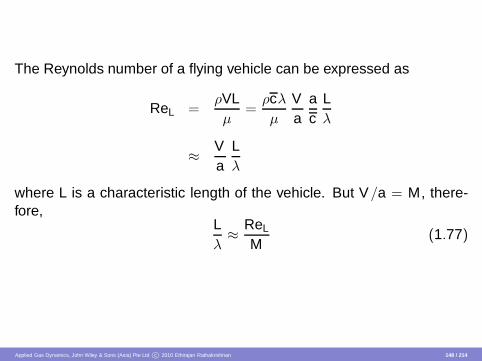
The Reynolds number of a flying vehicle can be expressed as
ReL =ρVLµ
=ρcλ
µ
Va
ac
Lλ
≈ Va
Lλ
where L is a characteristic length of the vehicle. But V/a = M, there-fore,
Lλ≈ ReL
M(1.77)
Applied Gas Dynamics, John Wiley & Sons (Asia) Pte Ltd c© 2010 Ethirajan Rathakrishnan 148 / 214

Equation (1.77) shows that, the ratio of Reynolds number to Mach num-ber is a dimensionless parameter indicative of whether a given problemis amenable to the continuum approach or not. From this ratio it is seenthat, the continuum hypothesis is likely to fail when the Mach numberis very large or the Reynolds number is extremely low. But we have toexercise caution while using Eq. (1.77), since ReL and M depend onthe nature of the problem considered. For example, when ReL is verylow owing to low density, the continuum hypothesis is not valid, whereaswhen it is very low due to high viscosity, the continuum concept is per-fectly valid and such a flow is termed stratified flow.
Applied Gas Dynamics, John Wiley & Sons (Asia) Pte Ltd c© 2010 Ethirajan Rathakrishnan 149 / 214
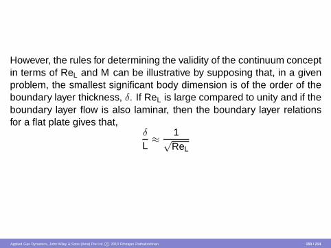
However, the rules for determining the validity of the continuum conceptin terms of ReL and M can be illustrative by supposing that, in a givenproblem, the smallest significant body dimension is of the order of theboundary layer thickness, δ. If ReL is large compared to unity and if theboundary layer flow is also laminar, then the boundary layer relationsfor a flat plate gives that,
δ
L≈ 1√
ReL
Applied Gas Dynamics, John Wiley & Sons (Asia) Pte Ltd c© 2010 Ethirajan Rathakrishnan 150 / 214

Using Eq. (1.77), this can be expressed as
δ
λ≈
√ReL
M
For this case Tsien (Tsien H.S., Super-aerodynamics, Mechanics ofRarefied gases, Jl. Aero. Sci., Vol. 13, No. 2 (1946), p. 653) suggeststhat the realm of continuum gas dynamics be limited to instances wherethe boundary layer thickness is at least 100 times the mean free path.That is √
ReL
M> 100
Applied Gas Dynamics, John Wiley & Sons (Asia) Pte Ltd c© 2010 Ethirajan Rathakrishnan 151 / 214

Figure 1.11 shows the Reynolds number per unit length as a function offlight Mach number for various altitudes, based on the standard atmo-sphere.
Mach number
Re/
Lx
106
0 1 2 3 40
20
40
60
80
100
3000 m
Sea level
15000 m
6000 m
9000 m
12000 m
Figure 1.11Reynolds number per meter versus Mach number, based on standard
atmosphere (E Rathakrishnan, Gas Tables, Second Edi. Universities Press,2004).
Applied Gas Dynamics, John Wiley & Sons (Asia) Pte Ltd c© 2010 Ethirajan Rathakrishnan 152 / 214

Compressible Flow Regimes
The compressible flow regime can be subdivided into different zonesbased on the local flow velocity and the local speed of sound. To do thisclassification, we can make use of the energy equation, as follows.
Consider a streamtube in a steady compressible flow in which the flowdoes not exchange heat with the fluid in neighboring streamtubes, i.e.the flow process is adiabatic. The steady-flow energy equation for theadiabatic flow through such a streamtube is
h +V 2
2= h0
where h and h0 are the static and stagnation enthalpies and V is theflow velocity.
Applied Gas Dynamics, John Wiley & Sons (Asia) Pte Ltd c© 2010 Ethirajan Rathakrishnan 153 / 214
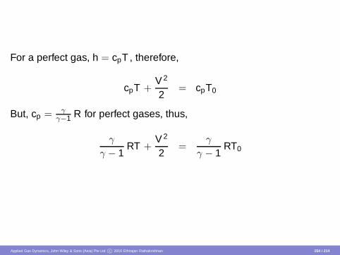
For a perfect gas, h = cpT , therefore,
cpT +V 2
2= cpT0
But, cp = γγ−1 R for perfect gases, thus,
γ
γ − 1RT +
V 2
2=
γ
γ − 1RT0
Applied Gas Dynamics, John Wiley & Sons (Asia) Pte Ltd c© 2010 Ethirajan Rathakrishnan 154 / 214

This simplifies to
V 2 +2
γ − 1a2 =
2γ − 1
a20 = V 2
max (1.78)
since a =√
γRT , the local speed of sound and a0 =√
γRT0, the speedof sound at the stagnation state (where V = 0) and Vmax is the maximumpossible flow velocity in the fluid (where the absolute temperature iszero).
Applied Gas Dynamics, John Wiley & Sons (Asia) Pte Ltd c© 2010 Ethirajan Rathakrishnan 155 / 214

Equation (1.78) represents an ellipse and is called as adiabatic steady-flow ellipse. The adiabatic ellipse can be plotted as in Figure 1.12.
V=
a
Incompressible
a0V
<a
a
V>
a
Subsonic
Supersonic
Transonic
Hypersonic
VVmax
Figure 1.12Steady-flow adiabatic ellipse.
Applied Gas Dynamics, John Wiley & Sons (Asia) Pte Ltd c© 2010 Ethirajan Rathakrishnan 156 / 214

Different realms of compressible flow having significantly different phys-ical characteristics are represented schematically on the adiabatic el-lipse. The zones highlighted on the adiabatic ellipse are the following.
Incompressible flow is the flow in which the flow speed, V is smallcompared to speed of sound, a in the flow medium. The changesin a are very small compared to changes in V .
Compressible subsonic flow is that in which the flow speed andspeed of sound of comparable magnitude, but V < a. Changes inflow Mach number M is mainly due to changes is V .
Applied Gas Dynamics, John Wiley & Sons (Asia) Pte Ltd c© 2010 Ethirajan Rathakrishnan 157 / 214
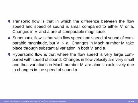
Transonic flow is that in which the difference between the flowspeed and speed of sound is small compared to either V or a.Changes in V and a are of comparable magnitude.
Supersonic flow is that with flow speed and speed of sound of com-parable magnitude, but V > a. Changes in Mach number M takeplace through substantial variation in both V and a.
Hypersonic flow is that where the flow speed is very large com-pared with speed of sound. Changes in flow velocity are very smalland thus variations in Mach number M are almost exclusively dueto changes in the speed of sound a.
Applied Gas Dynamics, John Wiley & Sons (Asia) Pte Ltd c© 2010 Ethirajan Rathakrishnan 158 / 214

Summary
Compressible flow is defined as variable density flow; this is in contrastto incompressible flow, where the density is assumed to be invariant.Usually flows with Mach number less than 0.3 are treated as constantdensity (incompressible) flows.
Applied Gas Dynamics, John Wiley & Sons (Asia) Pte Ltd c© 2010 Ethirajan Rathakrishnan 159 / 214

Gas Dynamics is a science that primarily deals with the behavior of gasflows in which compressibility and temperature change become sig-nificant. Compressibility is a phenomenon by virtue of which the flowchanges its density with change in speed. Compressibility may also bedefined as the volume modulus of the pressure.
Applied Gas Dynamics, John Wiley & Sons (Asia) Pte Ltd c© 2010 Ethirajan Rathakrishnan 160 / 214

Mach number is the ratio of the local flow speed to the local speed ofsound
M =Va
Flows with Mach number greater than unity are called supersonic flows.
Sound waves are infinitesimally small pressure disturbances. The speedwith which sound waves propagate in a medium is called speed ofsound a. The speed of sound is given by
a2 =dpdρ
Applied Gas Dynamics, John Wiley & Sons (Asia) Pte Ltd c© 2010 Ethirajan Rathakrishnan 161 / 214

For a perfect gas, the speed of sound can be expressed as
a =√
γRT
For a perfect gas, the state equation is
p = ρRT
For an isentropic flow of a perfect gas, the relation between the pres-sure, temperature and density between state 1 and any other state canbe expressed as
TT1
=
(
ρ
ρ1
)γ−1
=
(
pp1
)(γ−1)/γ
Applied Gas Dynamics, John Wiley & Sons (Asia) Pte Ltd c© 2010 Ethirajan Rathakrishnan 162 / 214
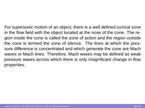
For supersonic motion of an object, there is a well defined conical zonein the flow field with the object located at the nose of the cone. The re-gion inside the cone is called the zone of action and the region outsidethe cone is termed the zone of silence. The lines at which the pres-sure difference is concentrated and which generate the cone are Machwaves or Mach lines. Therefore, Mach waves may be defined as weakpressure waves across which there is only insignificant change in flowproperties.
Applied Gas Dynamics, John Wiley & Sons (Asia) Pte Ltd c© 2010 Ethirajan Rathakrishnan 163 / 214

The angle between the Mach line and the direction of motion of thebody (flow direction) is called the Mach angle µ, given by
sin µ =1M
Applied Gas Dynamics, John Wiley & Sons (Asia) Pte Ltd c© 2010 Ethirajan Rathakrishnan 164 / 214

Modern classification of the flow regimes is as follows:1 Fluid flows with 0 < M < 0.8 are called subsonic flow.2 The flow in the Mach number range 0.8 < M < 1.2 is called tran-
sonic flow.3 The flow in the Mach number range 1.2 < M < 5 is called super-
sonic flow.4 The flow with M > 5 is called hypersonic flow.
Applied Gas Dynamics, John Wiley & Sons (Asia) Pte Ltd c© 2010 Ethirajan Rathakrishnan 165 / 214

Linearized theory can be used for studying subsonic and supersonicflows; the study of transonic and hypersonic flows is, however, compli-cated.
When a body is kept in transonic flow, it experiences subsonic flow oversome portions of its surface and supersonic flow over other portions.There is also a possibility of shock formation on the body. It is thismixed nature of the flow field which makes the study of transonic flowscomplicated.
Applied Gas Dynamics, John Wiley & Sons (Asia) Pte Ltd c© 2010 Ethirajan Rathakrishnan 166 / 214

The temperature at stagnation point and over the surface of an object inthe hypersonic flow becomes very high and, therefore, it requires spe-cial treatment. That is, we must consider the thermodynamic aspects ofthe flow along with gas dynamic aspects. That is why hypersonic flowtheory is also called aerothermodynamic theory. Besides, because ofhigh temperature, the specific heats become functions of temperatureand hence the gas cannot be treated as perfect gas. If the temperatureis quite high (of the order of more than 2000 K), even dissociation of gascan take place. The complexities due to high temperatures associatedwith hypersonic flow makes its study complicated.
Applied Gas Dynamics, John Wiley & Sons (Asia) Pte Ltd c© 2010 Ethirajan Rathakrishnan 167 / 214

Thermodynamics is the science that primarily deals with energy. Thefirst law of thermodynamics is simply an expression of the conservationof energy principle.
The second law of thermodynamics asserts that actual processes occurin the direction of increasing entropy.
A system of fixed mass is called a closed system, or control mass anda system that involves mass transfer across its boundaries is called anopen system, or control volume.
Applied Gas Dynamics, John Wiley & Sons (Asia) Pte Ltd c© 2010 Ethirajan Rathakrishnan 168 / 214

For an open system, by first law of thermodynamics, the energy equa-tion can be expressed as
H1 +m2
V 21 + m g z1 = H2 +
m2
V 22 + m g z2 + Ws − Q12
For a gas dynamic working process this equation becomes
H1 +m2
V 21 = H2 +
m2
V 22 + Ws − Q12
Applied Gas Dynamics, John Wiley & Sons (Asia) Pte Ltd c© 2010 Ethirajan Rathakrishnan 169 / 214

A process during which there is no heat transfer is called an adiabaticprocess.
A reversible process is a process which can be reversed to its initialstate without leaving any trace on the surroundings. That is, both thesystem and the surroundings are returned to their initial states at theend of the reverse process. Processes that are not reversible are calledirreversible processes.
Applied Gas Dynamics, John Wiley & Sons (Asia) Pte Ltd c© 2010 Ethirajan Rathakrishnan 170 / 214

A process which is adiabatic and reversible is called an isentropic pro-cess. The factors that change the entropy of a system are heat trans-fer and irreversibility. Many engineering systems or devices such asnozzles, diffusers and turbines are essentially adiabatic in their opera-tion and they perform best when the irreversibilities, such as the frictionassociated with the process, are minimized. Therefore, an isentropicprocess can serve as an appropriate model for actual processes.
Applied Gas Dynamics, John Wiley & Sons (Asia) Pte Ltd c© 2010 Ethirajan Rathakrishnan 171 / 214

A perfect gas is an imaginary substance that obeys the relation p =ρRT .
The amount of energy needed to raise the temperature of a unit massof a substance by one degree is called the specific heat at constant vol-ume, cv for a constant volume process and the specific heat at constantpressure, cp for a constant-pressure process. They are defined as
cv =
(
∂u∂T
)
v, cp =
(
∂h∂T
)
p
Applied Gas Dynamics, John Wiley & Sons (Asia) Pte Ltd c© 2010 Ethirajan Rathakrishnan 172 / 214

The specific heats ratio γ is defined as
γ =cp
cv
A gas is said to be perfect when it is thermally as well as caloricallyperfect. For a thermally perfect gas, u, h, cv , and cp are functions oftemperature alone.
For a calorically perfect gas, cp and cv are constants and are indepen-dent of temperature, i.e. a perfect gas has to be thermally as well ascalorically perfect.
Applied Gas Dynamics, John Wiley & Sons (Asia) Pte Ltd c© 2010 Ethirajan Rathakrishnan 173 / 214

Entropy may be viewed as a measure of disorder or randomness in asystem. The change in entropy can be expressed as
ds =δqT
+ dsirrev
The value of ds can be used to determine whether a process is re-versible, irreversible, or impossible:
Applied Gas Dynamics, John Wiley & Sons (Asia) Pte Ltd c© 2010 Ethirajan Rathakrishnan 174 / 214

For isentropic flow of a perfect gas,
p2
p1=
(
ρ2
ρ1
)γ
=
(
T2
T1
)γ/(γ−1)
T0
T= 1 +
γ − 12
M2
p0
p=
(
1 +γ − 1
2M2
)γ/(γ−1)
ρ0
ρ=
(
1 +γ − 1
2M2
)1/(γ−1)
Applied Gas Dynamics, John Wiley & Sons (Asia) Pte Ltd c© 2010 Ethirajan Rathakrishnan 175 / 214
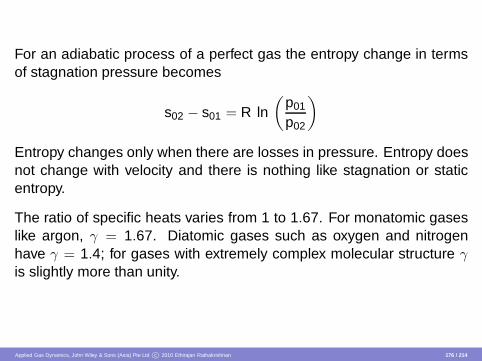
For an adiabatic process of a perfect gas the entropy change in termsof stagnation pressure becomes
s02 − s01 = R ln(
p01
p02
)
Entropy changes only when there are losses in pressure. Entropy doesnot change with velocity and there is nothing like stagnation or staticentropy.
The ratio of specific heats varies from 1 to 1.67. For monatomic gaseslike argon, γ = 1.67. Diatomic gases such as oxygen and nitrogenhave γ = 1.4; for gases with extremely complex molecular structure γis slightly more than unity.
Applied Gas Dynamics, John Wiley & Sons (Asia) Pte Ltd c© 2010 Ethirajan Rathakrishnan 176 / 214
When an object moves through a fluid medium, waves are emittedfrom each point on the object and travel outward at the speed ofsound. In an incompressible fluid, the speed of sound is infinite;therefore, the entire flow field could able to feel the motion of the objectinstantaneously. In a compressible medium, the speed of sound has afinite value and hence, if a body travels at a velocity greater than thatof sound, the fluid ahead of the body is not able to sense the motion ofthe object.
Applied Gas Dynamics, John Wiley & Sons (Asia) Pte Ltd c© 2010 Ethirajan Rathakrishnan 177 / 214

However, for subsonic motion of an object the fluid ahead of the objectcould able to sense the motion of the object. Therefore, for subsonicmotion, the fluid elements adjust and move smoothly around the object,resulting in smooth, continuous streamline patterns. For the supersoniccase, the fluid is forced to adjust rapidly to flow around a moving object,resulting in shock wave formation.
Applied Gas Dynamics, John Wiley & Sons (Asia) Pte Ltd c© 2010 Ethirajan Rathakrishnan 178 / 214

Exercise Problems
1.1 A gas has p = 1 atm, T = 0◦C and ρ = 0.09 kg/m3. Determine, (a)the characteristic gas constant and molecular weight of the gas and (b)the specific volume of the gas at 70◦C and 2.3 atm. Assume the gas tobe thermally perfect.[Ans. (a) 4.1217 kJ/(kg K), 2.017 kg, (b) 6.07 m3/kg]
1.2 A rigid tank contains a certain amount of nitrogen gas at 120 kPaand 30◦C, initially. Two kilograms of nitrogen gas is then added to thetank. If the final pressure and temperature of the gas in the tank are240 kPa and 30◦C, respectively, what is the volume of the tank?[Ans. 1.5 m3]
Applied Gas Dynamics, John Wiley & Sons (Asia) Pte Ltd c© 2010 Ethirajan Rathakrishnan 179 / 214

1.3 A barometer reads a local atmospheric pressure as 735 mm of mer-cury. How much is this pressure in pascals?[Ans. 98.061 kPa]
1.4 A mercury manometer reads the pressure inside a vessel as 200mm above atmosphere. The barometer reading is 750 mm Hg. Deter-mine the absolute pressure in the vessel in kPa?[Ans. 126.75 kPa]
Applied Gas Dynamics, John Wiley & Sons (Asia) Pte Ltd c© 2010 Ethirajan Rathakrishnan 180 / 214

1.5 A U-tube mercury manometer has its one limb connected to a pres-sure tank. The other end of the manometer is open to atmosphere. Ifthe manometer measures 250 cm, determine the pressure in the tank.[Ans. 434.63 kPa]
1.6 A water manometer reads the pressure inside a vessel as 500 mmbelow atmospheric pressure. If the atmospheric pressure is 760 mm ofHg, determine the absolute pressure in the vessel in kPa.[Ans. 96.49 kPa]
Applied Gas Dynamics, John Wiley & Sons (Asia) Pte Ltd c© 2010 Ethirajan Rathakrishnan 181 / 214

1.7 A Bourdon pressure gauge records a pressure of 1.5 MPa gauge. Ifthe atmospheric pressure is 740 mm Hg, determine the absolute valueof the pressure read by the Bourdon gauge.[Ans. 1.5987 MPa]
1.8 Determine the column height of a mercury manometer connectedto a gas tank at a pressure of 50 kPa. Find the difference in the fluidlevel if water is used instead of mercury. Assume ρHg = 13600 kg/m3
and ρw = 1000 kg/m3.[Ans. △h = 4.7223 m]
Applied Gas Dynamics, John Wiley & Sons (Asia) Pte Ltd c© 2010 Ethirajan Rathakrishnan 182 / 214
1.9 A force of 8000 N is exerted uniformly on a piston of 100 mm diam-eter. Determine the pressure at the piston face.[Ans. 1018.6 kPa]
1.10 An oil of specific gravity 0.8 is contained in a vessel to a depth of2.2 m. Determine the gauge pressure at the bottom of the vessel.[Ans. 17.27 kPa]
Applied Gas Dynamics, John Wiley & Sons (Asia) Pte Ltd c© 2010 Ethirajan Rathakrishnan 183 / 214

1.11 If the speed of sound at an altitude in earths atmosphere is 299m/s, determine the altitude.[Ans. 10076.9 m]
1.12 The noise of an aircraft in level flight flown overhead is heard byan observer at sea level altitude, only when the aircraft has travelled 1km from the location of the observer. Ignoring the temperature variationwith altitude, estimate the flight altitude if the aircraft is flying at Mach3.0.[Ans. 333.45 m]
Applied Gas Dynamics, John Wiley & Sons (Asia) Pte Ltd c© 2010 Ethirajan Rathakrishnan 184 / 214

1.13 Two disturbance spheres created by an object moving at a super-sonic speed are as shown in Figure 1.13. Assuming the medium to bestandard sea level atmosphere, calculate the Mach number and velocityof the object and the Mach angle of the cone created by the disturbance.
R = 3 m
R = 10 m
0
t = 0
t = tA
OV
23 m
Figure 1.13
[Ans. 3.286, 1117.24 m/s, 17.7◦]
Applied Gas Dynamics, John Wiley & Sons (Asia) Pte Ltd c© 2010 Ethirajan Rathakrishnan 185 / 214

1.14 A jet plane flies at 1100 kmph. Determine the flight Mach numberfor (a) sea–level operation with an air temperature of 25◦C and (b) high–altitude operation with an air temperature of − 55◦C.[Ans. (a) 0.883, (b) 1.03]
1.15 A stream of air drawn from a reservoir is flowing through an irre-versible adiabatic process into a second reservoir in which the pressureis half of that in the first. Calculate the entropy difference between thetwo reservoirs, at the beginning of the process.[Ans. 198.933 N.m/(kg K)]
1.16 Air is expanded in an insulated cylinder equipped with a frictionlesspiston. The initial temperature of the air is 1400 K. The original volumeis 1/10 of the final volume. Calculate (a) the change in temperature, (b)the work removed from the gas and (c) the pressure ratio.[Ans. (a) −842.65 K; (b) 6.04 × 10⁵ N.m/kg; (c) 25.1189]
Applied Gas Dynamics, John Wiley & Sons (Asia) Pte Ltd c© 2010 Ethirajan Rathakrishnan 186 / 214
1.17 A tank of volume 15 m3 contains air at p1 = 5.0 × 10⁵ Pa andT1 = 500 K. The air is discharged into the atmosphere through a nozzleuntil the mass of air in the tank is reduced to one-half of its originalvalue. Assuming the discharge be process adiabatic and frictionless,calculate the pressure and temperature of the air remaining in the tank.Assume the air as a perfect gas.[Ans. 1.8946 × 10⁵ Pa, 378.92 K]
1.18 Air is compressed isentropically in a centrifugal compressor froma pressure of 1.0 × 10⁵ Pa to a pressure of 6.0 × 10⁵ Pa. The initialtemperature is 290 K. Calculate (a) the change in temperature, (b) thechange in internal energy, (c) the work imparted to the air, neglectingthe velocity change.[Ans. (a) 193.868 K; (b) 1.39 × 10⁵ N.m/kg; (c) −1.39 × 10⁵ N.m/kg]
Applied Gas Dynamics, John Wiley & Sons (Asia) Pte Ltd c© 2010 Ethirajan Rathakrishnan 187 / 214

1.19 A perfect gas enclosed by an insulated (upright) cylinder and pistonis in equilibrium at conditions p1, v1, T1. A weight is placed on thepiston. After a number of oscillations, the motion subsides and the gasreaches a new equilibrium at conditions p2, v2, T2. Find the temperatureratio T2/T1 in terms of the pressure ratio λ = p2/p1. Show that, thechange of entropy is given by
s2 − s1 = R ln
1 + (γ − 1)λ
γ
γ/(γ−1) 1λ
Also show that, if the initial disturbance is small i.e. λ = 1 + ε, ε ≪ 1,then
s2 − s1
R≈ ε2
2γ[
Ans.T2
T1=
1 + (γ − 1)λ
γ
]
Applied Gas Dynamics, John Wiley & Sons (Asia) Pte Ltd c© 2010 Ethirajan Rathakrishnan 188 / 214

1.20 Unit weight of air is compressed adiabatically from an initial statewith p1 = 105 Pa and T1 = 303 K to a final state of p2 = 2 p1 and T2. Ifthe air enters and leaves the compressor with same velocity, calculatethe shaft work necessary. Assume air as an ideal gas.[Ans. ws = −66.66 kN-m/kg]
1.21 A fluid in a cylinder at a pressure of 6 atm and volume 0.3 m3 isexpanded at constant pressure to a volume of 2 m3. Determine thework done by this expansion.[Ans. 1.0335 MJ]
Applied Gas Dynamics, John Wiley & Sons (Asia) Pte Ltd c© 2010 Ethirajan Rathakrishnan 189 / 214

1.22 A gas at pressure 150 kPa and density 1.5 kg/m3 is compressedto 690 kPa isentropically. Determine the final density. Assume the isen-tropic index to be 1.3.[Ans. 4.85 kg/m3]
1.23 Air undergoes a change of state isentropically. The initial pressureand temperature are 101 kPa and 298 K, respectively. The final pres-sure is 7 times the initial pressure. Determine the final temperature.Assume air to be an ideal gas with specific heats ratio γ = 1.4.[Ans. 519.9 K]
Applied Gas Dynamics, John Wiley & Sons (Asia) Pte Ltd c© 2010 Ethirajan Rathakrishnan 190 / 214

1.24 Air at 30◦C is compressed isentropically to occupy a volume whichis 1/30 of its initial volume. Assuming air as an ideal gas, determine thefinal temperature.[Ans. 908.55◦C]
1.25 An ideal gas is cooled under constant pressure from 200◦C to50◦C. Assuming constant specific heats with cp = 1000 J/(kg K) andγ = 1.4, determine, (a) the molecular weight of the gas (b) the ratio offinal to initial volume of the gas.[Ans. (a) 29.1, (b) 0.683]
Applied Gas Dynamics, John Wiley & Sons (Asia) Pte Ltd c© 2010 Ethirajan Rathakrishnan 191 / 214

1.26 If the velocity of sound in an ideal gas of molecular weight 29 ismeasured to be 400 m/s at 100◦C, determine the cp and cv of the gasat 100◦C.[Ans. cp = 860.1 J/(kg K), cv = 573.4 J/(kg K)]
1.27 Air flows isentropically through a nozzle. If the speed and tempera-ture at the nozzle exit are 390 m/s and 28◦C, respectively, determine theMach number and stagnation temperature there. What will be the Machnumber just upstream of a station where the temperature is 92.5◦C?[Ans. 1.12, 103.29◦C, 0.387]
Applied Gas Dynamics, John Wiley & Sons (Asia) Pte Ltd c© 2010 Ethirajan Rathakrishnan 192 / 214
1.28 Hydrogen gas at 7 atm and 300 K in a cylinder is expanded isen-tropically through a nozzle to a final pressure of 1 atm. Assuming hy-drogen to be a perfect gas with γ = 1.4, determine the velocity andMach number corresponding to the final pressure. Also, find the massflow rate through the nozzle if the exit area is 10 cm2.[Ans. 1923 m/s, 1.93, 0.275 kg/s]
1.29 Air in a cylinder changes state from 101 kPa and 310 K to a pres-sure of 1100 kPa according to the process
pv1.32 = constant
Determine the entropy change associated with this process. Assumeair to be an ideal gas with cp = 1004 J/(kg K) and γ = 1.4.[Ans. −103.8 J/(kg K)]
Applied Gas Dynamics, John Wiley & Sons (Asia) Pte Ltd c© 2010 Ethirajan Rathakrishnan 193 / 214

1.30 Oxygen gas is heated from 25◦C to 125◦C. Determine the increasein its internal energy and enthalpy. Take γ = 1.4.[Ans. 64950 J/(kg K), 90930 J/(kg K)]
1.31 Air enters a compressor at 100 kPa and 1.175 kg/m3 and exits at500 kPa and 5.875 kg/m3. Determine the enthalpy difference betweenthe outlet and inlet states.[Ans. 0]
Applied Gas Dynamics, John Wiley & Sons (Asia) Pte Ltd c© 2010 Ethirajan Rathakrishnan 194 / 214

1.32 Show that, the entropy change for an ideal gas can be expressedas
ds = cpdvv
+ cvdpp
Using this result, show that for an ideal gas undergoing an isentropicchange of state with constant specific heats, pvγ = constant.
1.33 Certain quantity of air at 0.7 MPa and 150◦C occupies a volume of0.014 m3. If the gas is expanded isothermally to a volume of 0.084 m3,calculate the change of entropy.[Ans. 513.4 J/(kg K)]
Applied Gas Dynamics, John Wiley & Sons (Asia) Pte Ltd c© 2010 Ethirajan Rathakrishnan 195 / 214
1.34 0.3 kg of air at 350 kPa and 35◦C receives heat energy at constantvolume until its pressure becomes 700 kPa. It then receives heat energyat constant pressure until its volume becomes 0.2289 m3. Calculate theentropy change associated with each process.[Ans. 149.2 J/K, 333 J/K]
1.35 Air flowing through a frictionless diffuser. At a station in the diffuserthe temperature, pressure and velocity are 0◦C, 140 kPa and 900 m/s,respectively. At a downstream station the velocity decreases to 300 m/s.Assuming the flow to be adiabatic, calculate the increase in pressureand temperature of the flow between these stations.[Ans. 358.39 K, 2.491 MPa]
Applied Gas Dynamics, John Wiley & Sons (Asia) Pte Ltd c© 2010 Ethirajan Rathakrishnan 196 / 214

1.36 Nitrogen gas is compressed reversibly and isothermally from 100kPa and 25◦C to a final pressure of 300 kPa. Calculate the change inentropy.[Ans. − 0.3263 kJ/(kg K)]
1.37 Air undergoes a change of state isentropically from 300 K and110 kPa to a final pressure of 550 kPa. Assuming ideal gas behavior,determine the change in enthalpy.[Ans. 176.19 kJ/kg]
Applied Gas Dynamics, John Wiley & Sons (Asia) Pte Ltd c© 2010 Ethirajan Rathakrishnan 197 / 214

1.38 Air at low pressure inside a rigid tank is heated from 50◦C to125◦C. What is the change in entropy associated with this heating pro-cess?[Ans. 149.75 J/(kg K)]
1.39 Compute the temperature rise at the nose of an aircraft flying withMach number 2 at an altitude of 10,000 m.[Ans. 178.52]
Applied Gas Dynamics, John Wiley & Sons (Asia) Pte Ltd c© 2010 Ethirajan Rathakrishnan 198 / 214

1.40 A gas at an initial volume of 0.06 m3 and 15◦C is expanded to avolume of 0.12 m3 while the pressure remains constant. Determine thefinal temperature of the gas.[Ans. 303.15◦C]
1.41 Certain quantity of a gas at 140 kPa and volume 0.15 m3 is com-pressed to 700 kPa at constant temperature. Determine the final vol-ume of the gas.[Ans. 0.03 m3]
Applied Gas Dynamics, John Wiley & Sons (Asia) Pte Ltd c© 2010 Ethirajan Rathakrishnan 199 / 214

1.42 Calculate the speed of sound in nitrogen gas at 100◦C.[Ans. 393.85 m/s]
1.43 Find the value of the gas constant R for air in SI units.[Ans. 287.2 J/(kg K) or m2/(s2 K)]
Applied Gas Dynamics, John Wiley & Sons (Asia) Pte Ltd c© 2010 Ethirajan Rathakrishnan 200 / 214

1.44 Methane gas enters a constant area duct at 4 atm, 200◦C and 150m/s. At a downstream station 2, T2 = 400◦C and V2 = 250 m/s. De-termine p2, the mass flow rate and the entropy change between thesestations.[Ans. 3.414 atm, 247.9 kg/(m2 s), 835.86 J/(kg K)]
1.45 Gas flows through an insulated duct. At station 1 in the duct p1 =5 atm, T1 = 350 K and V1 = 55 m/s. At a downstream station 2, if p2 = 1atm and V2 = 300 m/s, determine T2 and the entropy difference s2 − s1
if the gas is (a) air and (b) argon.[Ans. (a) 306.7 K, 329.25 J/(kg K), (b) 266.11 K, 192.71 J/(kg K)]
Applied Gas Dynamics, John Wiley & Sons (Asia) Pte Ltd c© 2010 Ethirajan Rathakrishnan 201 / 214

1.46 Helium gas at 200 kPa kept in a closed tank is heated from 50◦C to100◦C. If the change in entropy is 1000 J/K, determine the new pressureand the mass of helium in the tank.[Ans. 230.94 kPa, 2.21 kg]
1.47 An aircraft flying at an altitude of 10000 m experiences a tempera-ture of 500◦C at its nose. Determine the flight Mach number.[Ans. 3.51]
Applied Gas Dynamics, John Wiley & Sons (Asia) Pte Ltd c© 2010 Ethirajan Rathakrishnan 202 / 214

1.48 Helium gas expands isentropically through a nozzle from state 1 tostate 2. If the pressure, temperature at state 1 are 108 kPa and 92◦C,respectively and the pressure and velocity at state 2 are 60 kPa and903 m/s, respectively, determine T2, M2, V1, M1, p0 and T0.[Ans. 289.05 K, 0.904, 139.02 m/s, 0.124, 109.38 kPa, 367 K]
1.49 Derive an expression for the entropy change in terms of pressuresfor a polytropic process of an ideal gas with constant specific heats.[
Ans. s2 − s1 = (n−γ) Rn (γ−1) ln
(
p2
p1
)]
Applied Gas Dynamics, John Wiley & Sons (Asia) Pte Ltd c© 2010 Ethirajan Rathakrishnan 203 / 214
1.50 The temperature and pressure of an unknown ideal gas in a cylin-der of volume 1 m3 are found to be 300 K and 6 atm, respectively. Themass of the gas in the cylinder is 975 g. Find the molecular weight ofthe gas.[Ans. 4 kg/kmol]
1.51 Ten grams of oxygen gas undergoes a change of state at constantinternal energy. Initial pressure and temperature are 2 atm and 330 K,respectively. The final volume occupied by the gas is twice the initialvolume. Calculate the final temperature and pressure and the changein entropy due to the state change. Assume oxygen to be an ideal gas.[Ans. 330 K, 1 atm, 1.8 J/K]
Applied Gas Dynamics, John Wiley & Sons (Asia) Pte Ltd c© 2010 Ethirajan Rathakrishnan 204 / 214

1.52 A cylinder of capacity 2 m3 contains oxygen gas at 600 kPa and30◦C. The gas is discharged from the cylinder till the pressure drops to350 kPa, keeping the temperature at the same level. Assuming idealgas behavior, determine the quantity of oxygen discharged.[Ans. 6.35 kg]
1.53 Determine the specific volume of an ideal gas at 1 atm and 0◦C.[Ans. 22.4 m3/kgmol]
Applied Gas Dynamics, John Wiley & Sons (Asia) Pte Ltd c© 2010 Ethirajan Rathakrishnan 205 / 214

1.54 An ideal gas has a molecular weight of 39.948. If its specific heatsratio at a given temperature is 1.67, determine cp and cv of the gas atthat temperature.[Ans. cp = 518.4 J/(kg K), cv = 310.4 J/(kg K)]
1.55 A rigid tank of volume 2 m3 contains oxygen gas at 50 kPa and50◦C. Another rigid tank of same volume contains oxygen gas at 30kPa and 25◦C. The two tanks are then connected. If the final equilibriumtemperature of the gas in both tanks is 25◦C, what is the final pressurein both the tanks? Treat the process to be isentropic.[Ans. 37.7 kPa]
Applied Gas Dynamics, John Wiley & Sons (Asia) Pte Ltd c© 2010 Ethirajan Rathakrishnan 206 / 214

1.56 If an airplane flies at 90 kmph at an altitude of 10000 m, findwhether it flies at supersonic speed or subsonic speed?[Ans. Flies at Mach 0.835]
1.57 Calculate the speed of sound in (a) air, (b) hydrogen, (c) methane,(d) oxygen, (e) carbon dioxide and (f) helium, at 100◦C.[Ans. (a) 387.21 m/s, (b) 1473.03 m/s, (c) 505.27 m/s, (d) 368.4 m/s, (e)302.71 m/s, (f) 1134.25 m/s]
Applied Gas Dynamics, John Wiley & Sons (Asia) Pte Ltd c© 2010 Ethirajan Rathakrishnan 207 / 214

1.58 A missile in flight experiences a pressure and a temperature of 4atm and 500 K, respectively, at its nose. Determine the density of air atits nose.[Ans. 2.824 kg/m3]
1.59 A pressure vessel of volume 15 m3 is filled with dry air at pressure10 atm and temperature 300 K. Compute the mass of air in the tank.[Ans. 176.52 kg]
Applied Gas Dynamics, John Wiley & Sons (Asia) Pte Ltd c© 2010 Ethirajan Rathakrishnan 208 / 214

1.60 Calculate the enthalpy of the air stored in the pressure vessel inproblem 59.[Ans. 53.19 MJ]
1.61 For a calorically perfect gas show that,
cp − cv = R
Applied Gas Dynamics, John Wiley & Sons (Asia) Pte Ltd c© 2010 Ethirajan Rathakrishnan 209 / 214

1.62 A gas initially at 140 kPa, 0.012 m3 and 100◦C is compressed toa final state with a pressure and volume of 2.8 MPa and 0.0012 m3,respectively, according to the law pVn = constant. Determine (a) thevalue of n, (b) temperature of the final state, (c) the work transfer and(d) the change of internal energy of the gas if R = 0.287 kJ/(kg K) andcv = 0.717 kJ/(kg K).[Ans. (a) 1.3, (b) 472.54◦C, (c) − 5.6 kJ, (d) 4.194 kJ]
1.63 One kilogram of gas at an initial pressure of 0.11 MPa and a tem-perature of 15◦C is compressed isothermally until the volume becomes0.1 m3. Determine, (a) the final pressure, (b) the final temperature and(c) the heat transfer associated with the process. Assume cp = 0.92kJ/(kg K) and cv = 0.66 kJ/(kg K), for the gas.[Ans. (a) 0.749 MPa, (b) 15◦C, (c) − 143.724 kJ]
Applied Gas Dynamics, John Wiley & Sons (Asia) Pte Ltd c© 2010 Ethirajan Rathakrishnan 210 / 214

1.64 Certain quantity of gas has an initial volume and temperature of 1.2liters and 150◦C, respectively. If it is expanded to a volume of 3.6 litersaccording to the law pV1.4 = constant, determine the final temperatureof the gas.[Ans. − 0.486◦C]
1.65 Certain quantity of gas at an initial pressure of 0.1 MPa and volume0.1 m3 is compressed to a pressure of 1.4 MPa according to the lawpV1.26 = constant. Determine the final volume of the gas.[Ans. 12.31 liters]
Applied Gas Dynamics, John Wiley & Sons (Asia) Pte Ltd c© 2010 Ethirajan Rathakrishnan 211 / 214

1.66 Certain mass of air initially at 1.3 MPa, 0.014 m3 and 135◦C isexpanded to a state where the pressure is 275 kPa and the volume is0.056 m3. Determine the mass and final temperature of the air.[Ans. 0.1554 kg, 72.14◦C]
1.67 Argon gas flows through a nozzle. At the nozzle inlet the pressureand density are 200 kPa and 1.2 kg/m3, respectively. At the nozzle exitthe pressure and temperature, respectively, are 100 kPa and 500◦C.Calculate the initial temperature, the final density, the changes in en-tropy and enthalpy of the gas due to the flow process.[Ans. 800.74 K, 0.621 kg/m3, 126.08 J/(kg K), − 14.31 kJ/kg]
Applied Gas Dynamics, John Wiley & Sons (Asia) Pte Ltd c© 2010 Ethirajan Rathakrishnan 212 / 214
1.68 An insulated tank is divided into two compartments of equal vol-ume by a diaphragm. One of the compartments is kept empty at vac-uum and the other contained a gas of unit mass. The diaphragm isbursted so that the gas fills both the compartments. Assuming the gasto be a perfect gas show that, the final temperature of the gas is thesame as the initial temperature and that the entropy increases by anamount γ−1
γ cp ln (2).
1.69 Show that, for an ideal gas the entropy change can be expressedas
∆s = cp ln(
v2
v1
)
+ cv ln(
p2
p1
)
Applied Gas Dynamics, John Wiley & Sons (Asia) Pte Ltd c© 2010 Ethirajan Rathakrishnan 213 / 214

1.70 Air flowing isentropically through a duct has a velocity and temper-ature of 100 m/s and 20◦C, respectively, at a particular station. Find thevelocity at a downstream station where the temperature is 5◦C.[Ans. 200.34 m/s]
1.71 A pitot-static probe placed in an air stream measures 214 mm ofmercury. If the stream pressure and temperature are 66 kPa and 9◦C,calculate its velocity.[Ans. 247.5 m/s]
Applied Gas Dynamics, John Wiley & Sons (Asia) Pte Ltd c© 2010 Ethirajan Rathakrishnan 214 / 214