application of mini heat pipes for thermal...
TRANSCRIPT

16th International Heat Pipe Conference (16th IHPC) Lyon, France, May 20-24, 2012
APPLICATION OF MINI HEAT PIPES FOR THERMAL MANAGEMENT OF OPTO-ELECTRONIC INSTRUMENTS
Sandeep Kumar Singh, Sameer Khandekar*
Department of Mechanical Engineering Indian Institute of Technology Kanpur
Kanpur (UP) 208016, India
Pankaj Srivastava, J. K. Bajpai Instrumentation Research and Development Establishment
Defense Research and Development Organisation Dehradun (UK), 248008 India
*Corresponding author: Tel: (+91)-512-259-7038, Fax: (+91)-512-259-7408, E-mail: [email protected] ABSTRACT Heat dissipation, thermal stresses, size and cost are the key packaging design issues for electronic and opto-electronic instruments. As per defense requirement, instruments are expected to work satisfactorily in the temperature range of -30oC to +55oC. In this study, we have explored the thermal management of a sealed enclosure, envisaged as housing for handheld instruments, using different active and passive techniques such as natural convection, conventional heat sinks and copper-water wicked mini-heat pipes. Microelectronic equipment inside the enclosure generated heat. The aim of the study was to apply and compare various thermal management techniques suitable for maintaining a safe operating temperature inside the enclosure. Transient numerical modeling was performed on a commercial platform to compare the various techniques available for thermal management. Effects of both, natural convection inside the enclosure and radiation, were taken into account. The results from the CFD simulations were verified with the real time system level experiments. It was observed that in handheld opto-electronic instruments, heat pipes have potential applications to achieve the required performance in the available enclosure volume. Keywords: Microelectronic thermal management, numerical modeling, heat pipes and heat sinks, effective thermal conductivity, passive cooling techniques 1. INTRODUCTION
Technological advancement at device, package and system levels led to increased product functionality but squeezed more power into ever-smaller packages. With these technologies, devices are capable of processing more data within a given space and time. This directly leads to enhanced heat generation per unit volume. Each conceived new design coming up in the market is with higher power dissipation levels. In addition, total dissipated power is not the only problem; heat density (power/area) is complementary to it. Major causes of electronic failures are due to temperature, vibration, humidity, dust levels etc. Thus, effective removal of heat and maintenance of safe operating temperature is most vital for reliable instrument operation [Khandekar et al., 2003].
Conventional heat sinks, pin fin arrays, fan-assisted heat sinks, phase-change materials (PCM), thermo electric coolers, etc. are some of the routine
techniques available for thermal management. Present scenario of high thermal loading coupled with high flux levels demands exploration of new heat transfer mechanisms. Efficient heat transfer by passive heat pipe technology is much superior to conventional techniques. Heat pipes, with their unique characteristics of very high thermal conductance, which usually is an order of magnitude larger than conventional metallic conductors, offer great potential for thermal management. Conventional wicked heat pipes allow rapid exchange of heat transfer through cyclic and passive evaporation and condensation processes of the working fluid. This continuous cycle can transfer large quantity of heat with very low thermal gradients [Garner, 1996].
The aims of this study (combination of modeling and experiments) are to incorporate and compare different available thermal management strategies for a ~35W power dissipating opto-electonic hand-held instrument for defense needs.
2. HEAT PIPE DESIGN AND TESTING
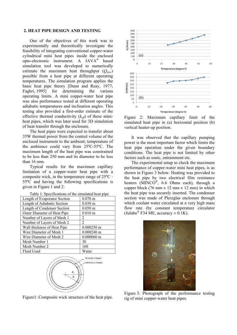
One of the objectives of this work was to experimentally and theoretically investigate the feasibility of integrating conventional copper-water cylindrical mini heat pipes inside the enclosed opto-electronic instrument. A JAVA® based simulation tool was developed to numerically estimate the maximum heat throughput (Qmax) possible from a heat pipe at different operating temperatures. The simulation program applies the basic heat pipe theory [Dunn and Reay, 1977; Faghri, 1995] for determining the various operating limits. A mini copper-water heat pipe was also performance tested at different operating adiabatic temperatures and inclination angles. This testing also provided a first-order estimate of the effective thermal conductivity (keff) of these mini-heat pipes, which was later used for 3D simulation of heat transfer through the enclosure.
(a)
(b)
The heat pipes were expected to transfer about 35W thermal power from the control volume of the enclosed instrument to the ambient; temperature of the ambience could vary from 25ºC-55ºC. The maximum length of the heat pipe was constrained to be less than 250 mm and its diameter to be less than 16 mm.
Typical results for the maximum capillary limitation of a copper-water heat pipe with a composite wick, in the temperature range of 25ºC - 55ºC and having the following specifications is given in Figure 1 and 2:
Table 1: Specifications of the simulated heat pipe Length of Evaporator Section 0.070 m Length of Adiabatic Section 0.030 m Length of Condenser Section 0.050 m Outer Diameter of Heat Pipe 0.010 m Number of Layers of Mesh 1 2 Number of Layers of Mesh 2 2 Wall thickness of Heat Pipe 0.000250 m Wire Diameter of Mesh 1 0.000240 m Wire Diameter of Mesh 2 0.000060 m Mesh Number 1 30 Mesh Number 2 160 Fluid Used Water
Figure1: Composite wick structure of the heat pipe.
Figure 2: Maximum capillary limit of the simulated heat pipe in (a) horizontal position (b) vertical heater-up position.
It was observed that the capillary pumping power is the most important factor which limits the heat pipe operation under the given boundary conditions. The heat pipe is not limited by other factors such as sonic, entrainment etc.
The experimental setup to check the maximum performance of copper-water mini heat pipes, is as shown in Figure 3 below. Heating was provided to the heat pipe by two electrical film resistance heaters (MINCO®, 6.6 Ohms each), through a copper block (76 mm x 12 mm x 12 mm) in which the heat pipe was securely inserted. The condenser section was made of Plexiglas enclosure through which coolant water circulated at a very high mass flow rate (by constant temperature circulator (Julabo® F34 ME, accuracy ± 0.1K).
Ro
Ri
Figure 3: Photograph of the performance testing rig of mini copper-water heat pipes.

The condenser capacity was at least three times larger than the maximum heat throughput expected from this heat pipe, as indicated by the simulations. Several thermocouples (Omega®, 0.5 mm bead diameter, accuracy ±0.1 after calibration) were attached throughout the length of the length of the heat pipe to monitor its thermal response. The data was recorded with the help of NI USB-9162 incorporating the LabVIEW® Signal Express 2009 platform. It was possible to incline the test bench at any desired inclination from the horizontal. Heat throughput to the evaporator was increased in small steps still a steady state was achieved, at a pre-decided adiabatic (operating) temperature. The operating temperature was maintained constant (from 25oC to 65oC at the interval of 5oC) by varying the condenser coolant inlet temperature. As dry-out approached, a sudden temperature increase in the evaporator section was observed. At any given adiabatic temperature, tests were repeated at least three times to ensure the repeatability of the dry-out phenomena and the corresponding heat throughput.
The maximum heat throughput which was obtained by the performance testing was compared with the theoretical values obtained in the simulation. A typical result of such a comparison is as shown in Figure 4. Here, the length of the copper-water heat pipe was of 280 mm and its outside diameter was 4 mm; the details of the internal wick structure are also depicted.
Figure 4: (a) Comparison of the theoretical and experimental values of maximum heat throughput of the copper-water mini heat pipe at different operating temperatures (vertical heater down position). (b) Porous wick inside the heat pipe. The depicted scale divisions are in millimeters.
3. MODELING AND SIMULATION
The opto-electronic device was conceived to be enclosed in an enclosure, as shown in Figure 5 (a). The overall structure is represented by the control volume, containing a heat source of 35 W with size 75 mm x 75 mm x 10 mm with embedded ‘heat pipes’, modeled by a high thermal conductivity rod of size 10 mm x 10 mm x 270 mm, as shown in Figure 5(b). The cross sectional area of the rod roughly represented three equivalent heat pipes, as proposed for use in the final thermal management protocol.
The outer aluminum casing of the device is thin walled. For simulation purpose, apart from heat source, the instrument box is primarily filled up with air. Inside the box, part of the heat transfer also takes place due to the natural convection from the heater surfaces to the air surrounding it. Over and above any forced convective system employed for thermal management, the eventual heat dissipation from the inside of the equipment to the ambient also includes heat transfer through the inside and outside walls of the thin walled casing, by a combination of natural convection and radiation. Several configurations of this basic arrangement were simulated (on Ansys-Fluent®
platform) as will be discussed later. Refined grids were taken at the boundaries of all the solid-fluid interfaces to resolve the boundary layers. A typical computational domain is as shown in Figure 6.
Internal structure of the heat pipe wick
(a) (b) Figure 5: (a) Schematic diagram of the enclosure (b) Volume fitted with heater and fan assembly.
Figure 6: Computational domain representation of the instrument enclosure.

For discretization of momentum and energy equation, ‘second order upwind’ scheme was applied. Absolute convergence criterion set for momentum was 10-6 and for energy was 10-8. The properties of air were set to be varying with the temperature.
The CFD simulations were run for the following two cases: Case #1: The heat pipe attached to the heating surface is not operational and the heating surface looses heat to the air inside the enclosure only by natural convection and radiation. The instrument enclosure eventually looses the heat gained by the inside heater to the ambient by natural convection and radiation taking place through the outside of the enclosure casing. The heat transfer coefficient assumed for natural convection is 6.5 W/m2K, while the average hemispherical emissivity of all the surfaces is taken to be 0.8. Case #2: The heat pipe attached to the power generating source is made active in this simulation. The effective thermal conductivity of the heat pipe is taken to be equal to 3000 W/mK, as suggested by the experiments. The heat pipe is connected to an external heat sink where forced convection is available with an effective heat transfer coefficient of 30 W/m2K. This heat pipe-heat sink based thermal energy transfer augmentation is in addition to the natural convection and radiation taking place, as described in Case #1.
Temperature distribution across the cross section of the instrument enclosure, for Case #1 is shown in Figure 7 (a). For this case, with only natural convection and radiation, the maximum temperature inside the enclosure comes out to be more than 400K. Thus, it is clear that such a solution is unfeasible for system deployment.
Figure 7: Temperature profile (Kelvin) at the cross section of the enclosure (a) without heat pipe and, (b) with the heat pipe attached to the heat source.
Figure 7(b) shows the temperature distribution across the cross section of the enclosure for Case #2. In this case, the maximum temperature reached inside the enclosure was just above 345K, in the vicinity of the heat source. The bulk temperature inside the enclosure was in the range of 320K to 340K. It is clear that integrating a heat pipe along with active convective cooling to the ambient drastically improves the thermal performance by keeping the internal temperatures at critical junctions below the prescribed values. 4. SYSTEM LEVEL EXPERIMENTS
A series of system level experiments were conducted to establish the effectiveness of different cooling methodologies operating under the actual environmental conditions. Figure 8 shows an enclosure which was made up of the aluminum casting. Heat sources dissipating about 35W of thermal energy were placed inside the enclosure. This enclosure was tested under different ambient temperatures, viz. 22oC, 35oC and 45oC. Three different operating conditions were used for the heat removal at these temperatures (a) Natural convection and radiation without any forced/active heat removal mechanism (b) Forced convection of air on the outside of the casing with the help of a fan and, (c) Use of three copper-water mini heat pipes of outside diameter 4.0 mm embedded inside the heat sources and connected to a finned hint sink outside the enclosure. A dedicated 12V axial flow mini-fan was integrated with the heat sink assembly, as shown in Figure 8. Temperatures were measured with the help of K-type thermocouples suitably located at six positions, two at the heater, two inside the enclosure, one each for ambient temperature and enclosure outer surface. Once a steady-state was reached, the temperatures at all the points were noted.
Figure 8: System level mock-up of the opto-electronic instrument enclosure.

The experiments with embedded heat pipe inside the enclosure were conducted in the real time situation to observe the effect of different operating conditions. The resulting temperature inside the enclosure can be observed in Figure 9 at different ambient temperatures (22oC, 35oC and 45oC) and different thermal management strategies. It was observed that, at all the ambient conditions, the temperature inside the enclosure was highest in the case where no heat pipe or heat sink was used. Even with the usage of heat sink, the temperature inside the enclosure remained high. But, when heat pipes were used along with the heat sink, coupled with active fan cooling from the outside, the maximum temperature inside the enclosure reduced significantly by 25oC at the ambient temperature of 45oC (In this case, the heat pipe was vertical-heater down). When the heat pipe assembly was kept at horizontal position there was some increase in the temperature inside the enclosure; the system worked somewhat more effectively when the heat pipe assembly was kept at the vertical position. Figure 10 compares the transient temperature profile inside the heater body for the three different cases. The advantages of the heat pipe heat sink are obvious.
Figure 9: Temperature obtained at a point inside the enclosure at different operating conditions and at different ambient temperatures.
Figure 10: Comparison of the three tested cases.
6. SUMMARY AND CONCLUSIONS
In handheld instrument needs for defense/ surveillance, weight, space and the extremities of the ambient conditions are the main constraints for design and development. Thermal management of such systems offer quite some challenge due to various design constraints and limitations. In the present study, it has been demonstrated that conventional mini-heat pipes offer very good potential to achieve the required performance in the available instrument volume.
Heat pipes offer an attractive approach to supplement conventional heat sink solutions. They do not replace the conventional heat sink, rather they provide a flexible tool that allows the designer to reconfigure and or extend the performance of conventional heat sinks. Considerably improved heat sink efficiency and performance was achieved for the opto-electronic instrument enclosure by relatively simple integration techniques. Use of such high conductively heat pipe interfaces permits higher packaging densities or higher power dissipation in a given volume. On many occasions, rather than the heat pipes, the series thermal circuit is limited by the external/ eventual heat dissipating mechanism (for example a heat sink to the ambient). The heat pipe usually provides least thermal resistance in the overall path.
In the present study, mini copper water heat pipes were successfully simulated, performance tested, and implemented in a system level mock-up experiment to dissipate about 35 W of thermal energy from the internal heat dissipating units. ACKNOWLEDGEMENTS The work was carried out with financial support from Instrument Research and Development Establishment (IRDE), Defense Research and Development Organization, Dehradoon, India. REFERENCES [1] Dunn, P., Reay, D.A., (1977), Heat Pipes, Second Edition, Pergamon Press. [2] Faghri, A., (1995), Heat Pipe Science and Technology. Taylor & Francis, London. [3] Garner, S., (1996), Heat pipes for Electronics Cooling Applications, Electronics Cooling, Vol. 2, No. 3. [4] Khandekar, S., Groll, M., Luckchoura, V., Findl, W. and Zhuang, J., (2003), Micro Heat Pipes for Stacked 3D Microelectronic Modules, Advances in Electronic Packaging, Vol. 2, pp. 245-251.