interpack2003 final 35109 -...
TRANSCRIPT

1 Copyright © 2003 by ASME
3URFHHGLQJV�RI�,3$&.��,QWHUQDWLRQDO�(OHFWURQLF�3DFNDJLQJ�7HFKQLFDO�&RQIHUHQFH�DQG�([KLELWLRQ
-XO\��±����������0DXL��+DZDLL��86$
InterPack 2003 - 35109
MICRO HEAT PIPES FOR STACKED 3D MICROELECTRONIC MODULES
Sameer Khandekar, Manfred Groll, Vivak LuckchouraInstitut für Kernenergetik und Energiesysteme (IKE), Universität Stuttgart, Pfaffenwaldring 31
70569 Stuttgart, Germany
Walter FindlElectrovac GmbH
Aufeldgasse 37, A-3400, Klosterneuburg, Austria
Jun ZhuangNanjing HETE Energy Conservation & Environmental Protection Co. Ltd.
Zhong Shan Development Zone, Dachang District, Nanjing, Jiangsu Province 210048 P. R. China
ABSTRACT
In context of a European Commission funded project,development of a standardized multifunctional stacked 3Dpackage was envisioned for potential applications in aviation,space and telecommunication sectors. The standardization andmodularity was aimed to integrate packages from differenttechnologies and to allow mutual slice inter-changeability.Thermal management solutions to the proposed new stacked3D package as per the project specifications (a total of threestacked substrate slices, each slice of size 55 × 55 × 1 mm3 andtotal package height not exceeding 10.5 mm) are reported here.Three potential options were studied i.e. (a) module liquidcooling, (b) integration of miniature copper-water cylindricalheat pipes (OD 3.0 mm) with the 1.0 mm substrate slice and (c)development of flat plate heat pipes of 0.9 mm thickness. Foroptions (a) and (b), initial tests have been performed takingaluminum as a representative material for AlSiC metal matrixcomposites which were to be employed in the final design.Further, copper based flat plate micro-structure conventionalheat pipes have been developed and performance tested.Thermal interactions have been investigated withthermocouples coupled with infrared thermography. For safeoperation up to 30W heating power (10W/slice), while thermaldiffusion through the bare metallic substrate is sufficient forheat transfer from chip to the substrate, micro heat pipes shouldbe employed to cool the substrate and transfer heat from it to anexternal cold plate. Flat plate heat pipes are advantageous forhigher power levels per slice. Interlayer thermal interactionsalso affect the response of stacked 3D packages.
KEY WORDS
3D packaging, thermal management, miniature heat pipes
INTRODUCTION
Packaging technologies play a key role in microelectronics.Progress in the direction of creating compact, lightweight andmulti-functional packages has resulted in the development ofthree-dimensional electronic modules. Modern day packagingtrends are miniaturization, higher component density, higherpower density and increased reliability. For these reasons highperformance PCBs are being increasingly replaced by stacked3D modules, especially using MCM technology.
In conjunction with this technology, 3D packaging offers awide range of advantages over conventional planar packages.Some of the advantages include [1, 2]: (a) increase inelectronics system density, miniaturization (b) increase insystem speed, reliability and performance (c) reduction in costsetc. Since the development of integrated circuits, it is knownthat an increase in electronic density leads to performanceimprovements and cost reduction. In parallel, the thermalmanagement of such highly integrated 3D packages facesconsiderable challenges. Many stringent demands of theforeseen potential applications of 3D technology are not met bythe present standards. Consequently, to overcome theselimitations, a research work was funded by the EuropeanCommission for the development of new stacked 3D packagingconcept, involving technology end users from avionics, spaceand telecom sectors.

2 Copyright © 2003 by ASME
In the present paper, the thermal aspects of stacked 3Dmodules studied under the framework of the above referredproject are reported. The thermal management was split up intodifferent critical levels and various proposed cooling conceptsi.e. liquid cooling, and integration of cylindrical and flat plateminiature heat pipes have been studied. The results of this studyare not only relevant for the specific project targets but aregeneric in nature.
SYSTEM SPECIFICATIONS AND GENERAL DESIGNOUTLINE
The techno-scientific objective of the project was todevelop high dissipative stacked 3D modules having thefollowing characteristics:
• Total thermal power dissipation of 30 W in 3 stacked slices,i.e. 10 W per slice
• Minimum possible volume and weight (a total of threestacked substrate layers, each slice of size 55 × 55 × 1 mm3
and total package height not exceeding 10.5 mm)• Modularity / standardized interchangeability• Adaptability for liquid cooling• Increase in reliability.
To achieve the target requirements of the project, a genericdesign, consisting of metallic frame substrate supports, withdesired thermal dies, signal interconnection hardware, modulehousing or casing, module I/O pins and stacking system, wasproposed. (see Fig. 1). The ‘slices’ as shown in the figure wereeither ‘active’ substrates (i.e. the slices are flat plate micro heatpipes) or ‘passive’ substrates (i.e. solid metallic plates made of
either copper alloy or combination of aluminum alloy andAlSiC metal matrix composite inserts). The thermo-mechanicalcommon demonstrator definitions included variousconfigurations of active/passive substrates, thermal dies,interconnection strategy as per the end user requirements fromavionics, space and telecom sectors. Thermal management ofthe stacked cubical module was divided into three levels [3]:
Level 1: At the substrate level; from chip to substrateLevel 2: From substrate to module casingLevel 3: From casing to the external ambient
The frames were designed to have the following vitalfunctions [4]:
Mechanical: To allow the mounting of electronics, stackinginside the casing, overall integrity of the cubical module,
Thermal: to achieve successful thermal management at level 1and 2,
Electrical: to integrate electrical interconnections and achievemutual signal transfer within the stacked layers and external I/Opin matrix.
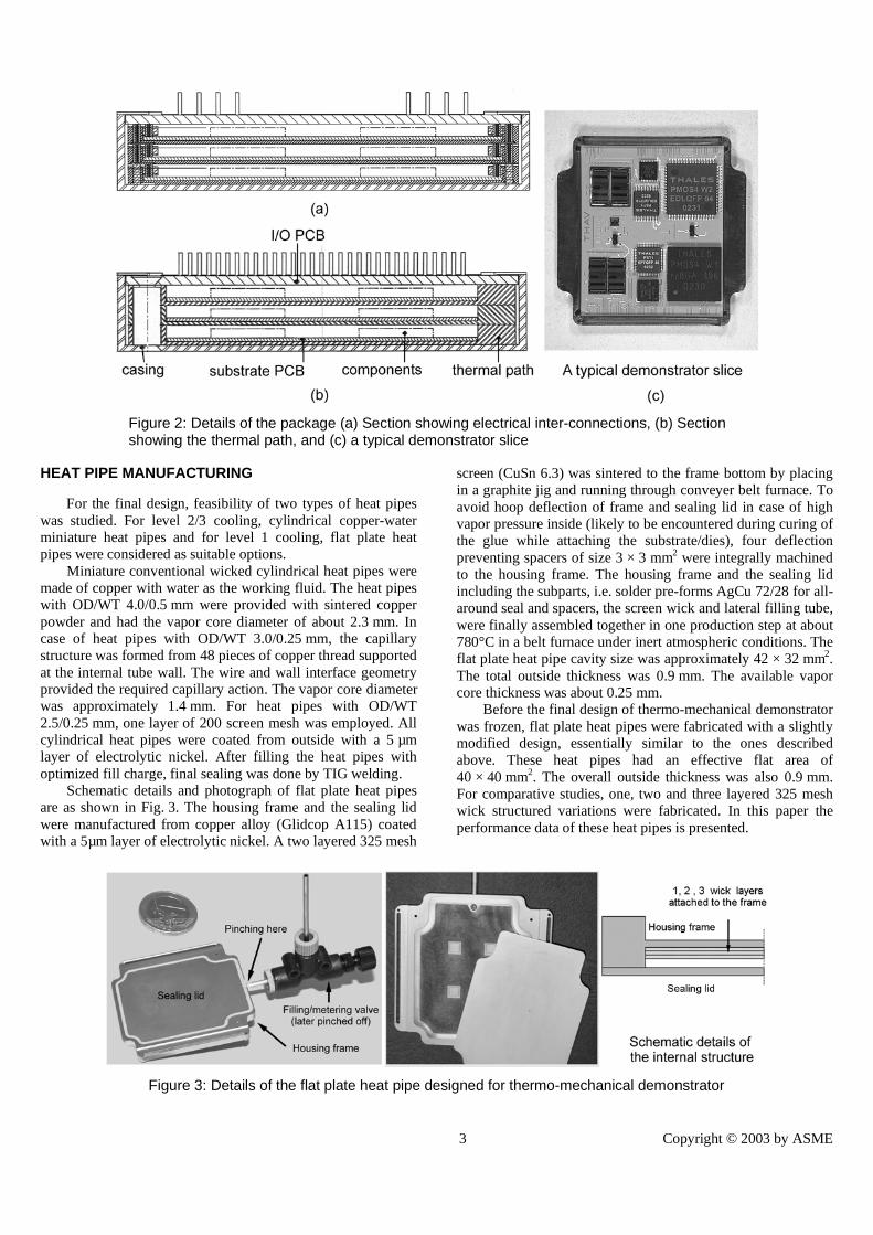
The typical ‘slice’ was designed in such a way so as tophysically isolate the thermal passage and the signalrouting/transfer functionality. Figure 2 shows the cut sectionsof the designed module structure and a typical substrate slice.The electrical interconnections between the stacked layers wererequired in the vertical and horizontal direction. The verticalinterconnections were achieved by elastomeric flexible Zebra®strip connectors while the horizontal interconnections wereachieved by tailor-made routing PCBs.
Figure 1: Design details of the proposed stacked 3D modular package
3 Copyright © 2003 by ASME
HEAT PIPE MANUFACTURING
For the final design, feasibility of two types of heat pipeswas studied. For level 2/3 cooling, cylindrical copper-waterminiature heat pipes and for level 1 cooling, flat plate heatpipes were considered as suitable options.
Miniature conventional wicked cylindrical heat pipes weremade of copper with water as the working fluid. The heat pipeswith OD/WT 4.0/0.5 mm were provided with sintered copperpowder and had the vapor core diameter of about 2.3 mm. Incase of heat pipes with OD/WT 3.0/0.25 mm, the capillarystructure was formed from 48 pieces of copper thread supportedat the internal tube wall. The wire and wall interface geometryprovided the required capillary action. The vapor core diameterwas approximately 1.4 mm. For heat pipes with OD/WT2.5/0.25 mm, one layer of 200 screen mesh was employed. Allcylindrical heat pipes were coated from outside with a 5 µmlayer of electrolytic nickel. After filling the heat pipes withoptimized fill charge, final sealing was done by TIG welding.
Schematic details and photograph of flat plate heat pipesare as shown in Fig. 3. The housing frame and the sealing lidwere manufactured from copper alloy (Glidcop A115) coatedwith a 5µm layer of electrolytic nickel. A two layered 325 mesh
screen (CuSn 6.3) was sintered to the frame bottom by placingin a graphite jig and running through conveyer belt furnace. Toavoid hoop deflection of frame and sealing lid in case of highvapor pressure inside (likely to be encountered during curing ofthe glue while attaching the substrate/dies), four deflectionpreventing spacers of size 3 × 3 mm2 were integrally machinedto the housing frame. The housing frame and the sealing lidincluding the subparts, i.e. solder pre-forms AgCu 72/28 for all-around seal and spacers, the screen wick and lateral filling tube,were finally assembled together in one production step at about780°C in a belt furnace under inert atmospheric conditions. Theflat plate heat pipe cavity size was approximately 42 × 32 mm2.The total outside thickness was 0.9 mm. The available vaporcore thickness was about 0.25 mm.
Before the final design of thermo-mechanical demonstratorwas frozen, flat plate heat pipes were fabricated with a slightlymodified design, essentially similar to the ones describedabove. These heat pipes had an effective flat area of40 × 40 mm2. The overall outside thickness was also 0.9 mm.For comparative studies, one, two and three layered 325 meshwick structured variations were fabricated. In this paper theperformance data of these heat pipes is presented.
Figure 3: Details of the flat plate heat pipe designed for thermo-mechanical demonstrator
Figure 2: Details of the package (a) Section showing electrical inter-connections, (b) Sectionshowing the thermal path, and (c) a typical demonstrator slice
4 Copyright © 2003 by ASME
EXPERIMENTAL SET-UPS AND RESULTS
At the time of writing of this technical report, the finalrange of thermo-mechanical common demonstrators were beingfabricated. The final results as per the specified test file will bereported at a later date. Before finalizing the demonstratordesign, various mock-up tests were conducted as part of thefeasibility study. In the following sub-sections results fromthese tests are presented.
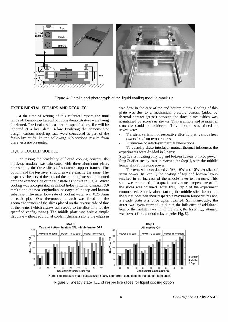
LIQUID COOLED MODULE
For testing the feasibility of liquid cooling concept, themock-up module was fabricated with three aluminum platesrepresenting the three slices of substrate support frames. Thebottom and the top layer structures were exactly the same. Therespective heaters of the top and the bottom plate were mountedonto the exterior side of the substrate as shown in Fig. 4. Watercooling was incorporated in drilled holes (internal diameter 3.0mm) along the two longitudinal passages of the top and bottomsubstrates. The mass flow rate of coolant water was 0.25 l/minin each pipe. One thermocouple each was fixed on thegeometric centers of the slices placed on the reverse side of thatof the heater (which always correspond to the slice Tmax for thespecified configuration). The middle plate was only a simpleflat plate without additional coolant channels along the edges as
was done in the case of top and bottom plates. Cooling of thisplate was due to a mechanical pressure contact (aided bythermal contact grease) between the three plates which wasmaintained by screws as shown. Thus a simple and symmetricstructure could be achieved. This module was aimed toinvestigate:• Transient variation of respective slice Tmax at various heat
powers / coolant temperatures.• Evaluation of interlayer thermal interactions.
To quantify these interlayer mutual thermal influences theexperiments were divided in 2 parts:Step 1: start heating only top and bottom heaters at fixed powerStep 2: after steady state is reached for Step 1, start the middleheater also at the same power.
The tests were conducted at 5W, 10W and 15W per slice ofinput power. In Step 1, the heating of top and bottom layersresulted in an increase of the middle layer temperature. Thisstate was continued till a quasi steady state temperature of allthe slices was obtained. After this, Step 2 of the experimentcommenced. Shortly after starting the middle slice heater, allthe slices obtained their respective maximum temperatures anda steady state was once again reached. Simultaneously, theouter two layers warmed up due to the influence of additionalheat of the middle layer. In all the trials, the layer Tmax attainedwas lowest for the middle layer (refer Fig. 5).
Figure 5: Steady state Tmax of respective slices for liquid cooling option
Figure 4: Details and photograph of the liquid cooling module mock-up

5 Copyright © 2003 by ASME
CYLINDRICAL HEAT PIPE INTEGRATED MODULE
Experimental studies for single substrate layer underdifferent operating conditions with integrated copper-watermicro heat pipes (OD/WT 3.0/0.25 mm) were designed asoutlined in Fig. 6. The aluminum substrate structure of the heatpipe integrated module was exactly like the previous structureused for water cooled tests. Instead of coolant water flowingthrough the drilled channels, two heat pipes were used forcooling. These heat pipes were mechanically integrated indrilled channels along the longitudinal edges of the substrate.The remaining portion of the heat pipe was mechanicallyinserted into a standard finned air cooled aluminum heat sink.An axial fan with air velocity of 3 m/s was used for cooling. Allexperiments were conducted in horizontal position of the set up(and so also the heat pipes). For reference measurements, onetype-K thermocouple was placed at the geometric center of thesubstrate and the whole set-up was viewed with an infra-redthermocamera. The infrared camera was properly calibratedwith standard emitting surface before the experiment. Theaccuracy of temperature measurement was within � 0.3°C.
The obtained results for layer Tmax are shown in Fig. 7-a,where the improved cooling effect of the air cooled heat pipesolution as against the water cooling solution can be seen. Atypical thermograph is also shown in Fig. 7-b.
HEAT PIPE PERFORMANCE EVALUATION
Cylindrical heat pipes
It was demonstrated by the previous tests that the 3.0 mmcopper water micro heat pipes were able to meet the specifiedproject boundary conditions. For a more broader outlook on thepossible areas of applications, it was decided to carry outperformance evaluation of a range of mini cylindrical copper-water heat pipes. In this study mini heat pipes with OD/WT4.0/0.5 mm, 3.0 /0.25 mm and 2.5 mm/0.25 mm were tested.
The heat pipes were mechanically inserted into suitablysized copper blocks with application of thermal paste. Twosurface mountable ceramic heaters were attached to the copperblock to form the evaporator section. The condenser was madeof Makrolon® (Plexiglass) with drilled passages for coolant
water flow. Heat pipes were firmly located in this section bynatural rubber stoppers. The entire set-up was well insulated. Inall set-ups, three thermocouples were placed in the evaporatorsection, two in the adiabatic section and two in the condensersection. The entire set-up could be tilted at the desired angle.
The structures were tested with standard heat pipeperformance testing procedures. The operating temperature,which corresponds to the adiabatic section temperature, wasalways maintained at a fixed value (by adjusting the condensercoolant temperature), as the heater input power was increasedin small steps. A sudden surge in evaporator temperaturecorresponds to the dryout phenomenon inside the evaporator.The power step just before the dryout reflects the maximumperformance at the fixed operating adiabatic temperature. Thisis shown in Fig. 8-a, b for vertical and horizontalconfigurations, for all the range of tested structures. It is seenfrom the figure that the maximum performance drasticallyreduces with decreasing capillary diameter. In addition, themanufacturing complexity associated with small diametercapillary wicked heat pipes also increases with decreasing tubediameter.
Flat plate micro heat pipe
As stated earlier, tests were conducted to evaluate theperformance of flat plate heat pipes. The experimental set-up isshown in Fig. 9. A surface mountable ceramic DC heater(40 × 10 mm2) provided the necessary input power while thecooling was achieved by pumping water through a 9 mm holein a copper cold plate (15 × 15 × 80 mm3) attached to the heatpipe. The effective length of the heat pipe was 27.5 mm.Thermographic profiles could be seen by an infrared camerafrom the exposed side as shown in Fig. 9. The heat pipes weretested in the vertical orientation (heater down).
Figure 10 shows the performance results for three layeredwick (mesh 325) and two layered wick (mesh 325). An increasein the wick layers increases the liquid flow area but on the otherhand decreases the available vapor volume. So, a trade-off hasto be achieved between the liquid and vapor pressure drops vis-à-vis the available space. For the present design a two-layeredstructure gave best results as compared to one and three-layeredwicked heat pipes.
Figure 6: Details of the cylindrical heat pipe integration set-up

6 Copyright © 2003 by ASME
Figure 7: (a) Steady state slice Tmax for integrated heat pipe option, (b) Typical thermograph of the set-up
(a) (b)
Figure 9: Details of the experimental set-up for performance testing of flat plate heat pipes
Figure 8: Maximum performance of miniature cylindrical heat pipes (a) in vertical, (b) in Horizontal orientation

7 Copyright © 2003 by ASME
CONCLUSIONS
A new concept for stacked 3D layers has been defined. Thestacked layers are multifunctional and cater to die mountingand electrical interconnections, mechanical integrity andthermal requirements of the package. The thermal managementhas been successfully dealt with on various critical levels.
Flat plate heat pipes with maximum thickness of 0.9 mmhave been successfully developed and preliminary performancetests have shown promising results. Although the thermaladvantage is not substantial at relatively lower power inputs (10W per slice as tested in the present experiments) as compared tosolid copper plates of equivalent dimensions, the option is wellsuited for higher power dissipation levels.
Cylindrical miniature copper-water heat pipes in thediameter range of 2 mm to 4 mm have also been developed.These have been successfully integrated with the definedstacked 3D substrates. In the case of single substrate layerintegrated with two mini heat pipes (OD 3.0 mm), themaximum power transmitted for safe operation at Tmax<100°Cwas about 22 W for an air velocity of 3 m/s at about 25° C. Thetesting of such heat pipes has revealed that the maximumperformance drops very fast with the decrease in internaldiameter. Nevertheless, down to about 2.5 mm internaldiameter copper-water conventional wicked heat pipes are quitepromising. Below this diameter, limitations arise not only dueto thermo-physical properties of the working fluid but also dueto manufacturing constraints related to wick construction [5].
The option of cooling stacked modules with liquidcirculation has also been tested. For 15 W per layer (heat flux =6.5 W/cm²) and Tcoolant = 60°C (worst case), slice Tmax
a100°C. For 10W per layer applied to the substrate (projectspecifications), following Tmax were obtained in case of liquidcooling: coolant at 20°C: Tmax = 52°C, coolant at 40°C: Tmax =70°C, coolant at 60°C: Tmax = 88°C. Although the presentproject requirements were met with liquid cooling, integralcylindrical copper-water heat pipes achieved better results on acomparative basis.
Interlayer interactions also affect the thermal behavior ofthe 3D structure depending on the geometry of thermalinterconnections and thermal bridges, if any [3].
ACKNOWLEDGMENT
The authors gratefully acknowledge the support providedby the European Commission for this research carried out in theframe of project N° GRD1-1999-10360-‘MCUBE’. The projectpartners were Thales Avionics, Alcatel Space, Nokia, CustomsInterconnect Ltd, Electrovac GmbH, IKE and INSA.
REFERENCES
[1] Brown W. D., 1999, “Advanced Electronic Packaging”,Institute of Electrical and Electronics Engineers (IEEEPress).
[2] Garrou P. and Turlik I., 1998, “Multichip ModuleTechnology Handbook”, McGraw Hill, pp. 13.1-13.31.
[3] Khandekar S., Welte T. and Groll M., 2002, “ThermalManagement of 3D Microelectronic Modules-Experimental and Simulation Studies”, Proc. 12th Int.Heat Pipe Conf., pp. 384-389, Moscow.
[4] Venet N., 2002, “MCUBE: An European Project toDevelop a 3D Concept to Dissipate 30 Watts”, Proc.ESCCON 2002, Toulouse.
[5] Chen H., Groll M. and Rösler S., 1992, “Micro HeatPipes: Experimental Investigation and TheoreticalModeling”, Proc. 8th Int. Heat Pipe Conf., pp. 396-400,Beijing.
Figure 10: Performance of the flat plate heat pipes