appendix g alderwood water & wastewater … · appendix g . alderwood water & wastewater...
TRANSCRIPT
APPENDIX G
ALDERWOOD WATER & WASTEWATER DISTRICT DEVELOPMENT STANDARDS & SPECIFICATIONS
DIVISIONS 3, 5, 6, AND 7
Swamp Creek Interceptor Extension Project No. S1209

Alderwood Water & Wastewater District Effective date 5/6/2013 Development Standards Division 3 – Sewer Installation Page 1 of 12
DIVISION 3
Standards
for
Sewer Installation
Alderwood Water & Wastewater District Effective date 5/6/2013 Development Standards Division 3 – Sewer Installation Page 2 of 12
Division 3
Standards for Sewer Installation
Table of Contents 3-1.000 SANITARY SEWER INSTALLATION ....................................................................... 3 3-1.010 General ..................................................................................................................... 3 3-1.020 Construction Standards ............................................................................................. 3 3-2.000 MATERIALS AND INSTALLATION .......................................................................... 3 3-2.010 General ..................................................................................................................... 3 3-2.020 Pipe Materials ........................................................................................................... 3 3-2.030 Pipe Installation ......................................................................................................... 4 3-2.040 Lampholes ................................................................................................................. 7 3-2.050 Side Sewer Laterals .................................................................................................. 7 3-2.060 Precast Concrete Manholes ...................................................................................... 8 3-3.000 TESTING ................................................................................................................. 10
DETAILS Open ..........................................................................................................................................S-1 Open ..........................................................................................................................................S-2 Standard Precast Manhole ........................................................................................................S-3 Saddle Manhole .......................................................................................................................S-3A Polypropylene Ladder and Manhole Steps ................................................................................S-4 Manhole Frame and Cover ........................................................................................................S-5 Shallow Manhole .......................................................................................................................S-6 Open ..........................................................................................................................................S-7 Drop Manhole Connection .........................................................................................................S-8 Force Main, Drop Manhole Connection ………………………………………………………….…S-8A Lamphole / Cleanout ..................................................................................................................S-9 Sewer Lateral – New Construction ...........................................................................................S-10 Alternate Lateral Sewer - New Construction ..........................................................................S-10A Standing Lateral Sewer – New Construction ………………….…..……………………..………S-10B Sewer Lateral – Existing Mains ................................................................................................S-11
Alderwood Water & Wastewater District Effective date 5/6/2013 Development Standards Division 3 – Sewer Installation Page 3 of 12
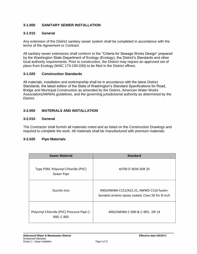
3-1.000 SANITARY SEWER INSTALLATION 3-1.010 General Any extension of the District sanitary sewer system shall be completed in accordance with the terms of the Agreement or Contract. All sanitary sewer extensions shall conform to the “Criteria for Sewage Works Design” prepared by the Washington State Department of Ecology (Ecology), the District’s Standards and other local authority requirements. Prior to construction, the District may require an approved set of plans from Ecology (WAC 173-240-030) to be filed in the District offices. 3-1.020 Construction Standards All materials, installation and workmanship shall be in accordance with the latest District Standards, the latest edition of the State of Washington‘s Standard Specifications for Road, Bridge and Municipal Construction as amended by the District, American Water Works Association(AWWA) guidelines, and the governing jurisdictional authority as determined by the District. 3-2.000 MATERIALS AND INSTALLATION 3-2.010 General The Contractor shall furnish all materials noted and as listed on the Construction Drawings and required to complete the work. All materials shall be manufactured with premium materials. 3-2.020 Pipe Materials
Sewer Material Standard
Type PSM, Polyvinyl Chloride (PVC)
Sewer Pipe
ASTM D 3034 SDR 35
Ductile Iron
ANSI/AWWA C151/A21.51, AWWD C116 fusion-
bonded ceramic epoxy coated, Class 50 for 8-inch
Polyvinyl Chloride (PVC) Pressure Pipe C-
900, C-905
ANSI/AWWA C-900 & C-905, DR 14
Alderwood Water & Wastewater District Effective date 5/6/2013 Development Standards Division 3 – Sewer Installation Page 4 of 12
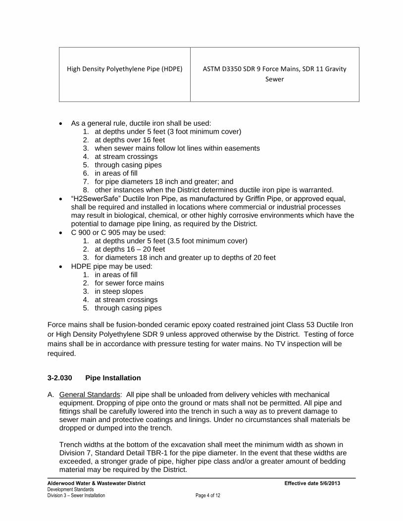
High Density Polyethylene Pipe (HDPE)
ASTM D3350 SDR 9 Force Mains, SDR 11 Gravity
Sewer
As a general rule, ductile iron shall be used: 1. at depths under 5 feet (3 foot minimum cover) 2. at depths over 16 feet 3. when sewer mains follow lot lines within easements 4. at stream crossings 5. through casing pipes 6. in areas of fill 7. for pipe diameters 18 inch and greater; and 8. other instances when the District determines ductile iron pipe is warranted.
“H2SewerSafe” Ductile Iron Pipe, as manufactured by Griffin Pipe, or approved equal, shall be required and installed in locations where commercial or industrial processes may result in biological, chemical, or other highly corrosive environments which have the potential to damage pipe lining, as required by the District.
C 900 or C 905 may be used: 1. at depths under 5 feet (3.5 foot minimum cover) 2. at depths 16 – 20 feet 3. for diameters 18 inch and greater up to depths of 20 feet
HDPE pipe may be used: 1. in areas of fill 2. for sewer force mains 3. in steep slopes 4. at stream crossings 5. through casing pipes
Force mains shall be fusion-bonded ceramic epoxy coated restrained joint Class 53 Ductile Iron
or High Density Polyethylene SDR 9 unless approved otherwise by the District. Testing of force
mains shall be in accordance with pressure testing for water mains. No TV inspection will be
required.
3-2.030 Pipe Installation A. General Standards: All pipe shall be unloaded from delivery vehicles with mechanical
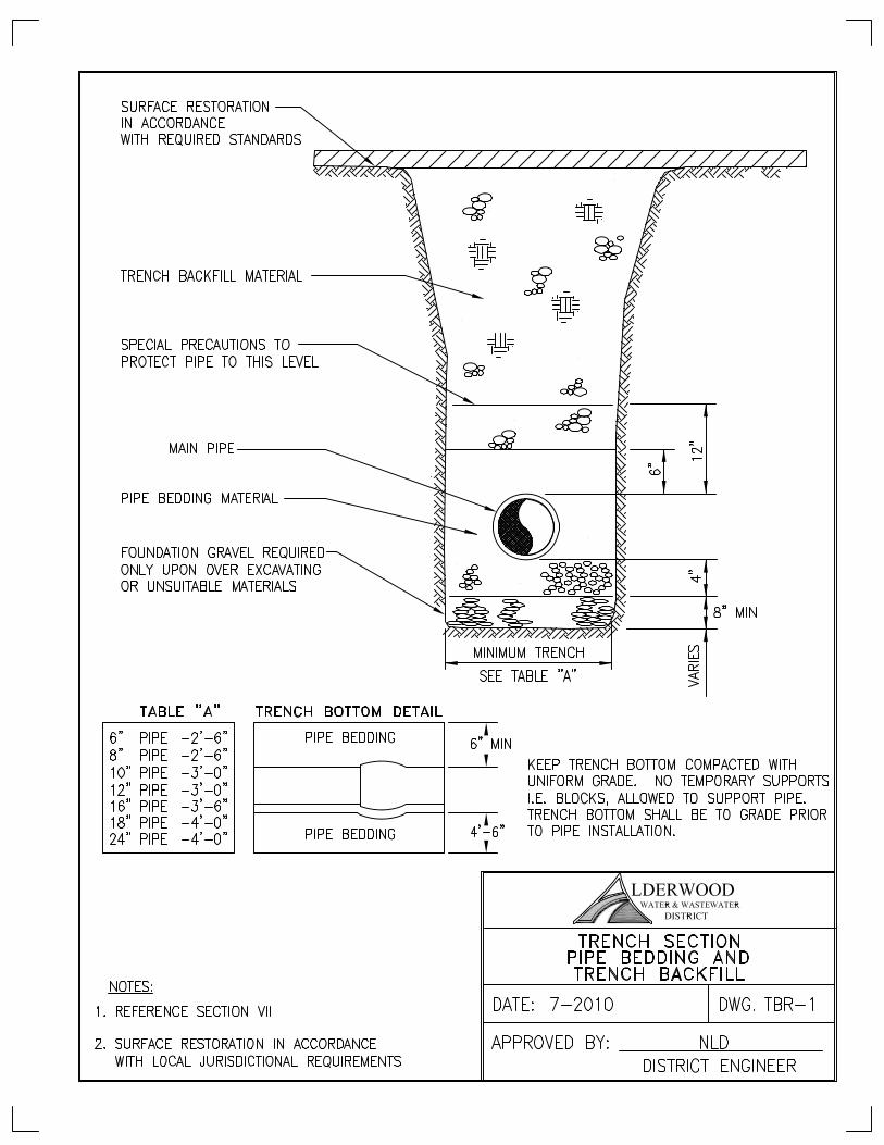
equipment. Dropping of pipe onto the ground or mats shall not be permitted. All pipe and fittings shall be carefully lowered into the trench in such a way as to prevent damage to sewer main and protective coatings and linings. Under no circumstances shall materials be dropped or dumped into the trench. Trench widths at the bottom of the excavation shall meet the minimum width as shown in Division 7, Standard Detail TBR-1 for the pipe diameter. In the event that these widths are exceeded, a stronger grade of pipe, higher pipe class and/or a greater amount of bedding material may be required by the District.

Alderwood Water & Wastewater District Effective date 5/6/2013 Development Standards Division 3 – Sewer Installation Page 5 of 12
Bell holes shall be excavated in the bedding material to allow for unobstructed assembly of the joint. Care should be taken that the bell hole is no larger than necessary to accomplish proper joint assembly. When the joint has been made, the bell hole should be carefully filled with bedding material to provide for support of the pipe throughout its entire length. Immediately upon beginning pipe installation, the Contractor shall place and secure a watertight plug in the sewer main at the new or existing manhole as directed by the District; plug shall be secured with a chain and attached to the ladder inside the manhole. The plug shall remain in place throughout the project until such time as the project is accepted by the District. Failure to place the plug or removal of a plug prior to District acceptance shall be grounds for District issued penalties as established by resolution. Contractor is responsible to remove plug upon final acceptance of the sewer. Under no circumstances shall the Contractor be allowed to discharge flows from the new sewer main into the District system until or unless approved by the District. Gravity sewers shall be designed and installed in a straight alignment with uniform grade and pipe type between manholes. Variance from established line and grade can be up to one-inch (1"), provided that it falls within a localized area not to exceed 20 feet or one pipe length. Variation in the invert elevation between adjoining ends of pipe due to non-concentricity of joining surface and/or pipe interior surfaces (in the direction of flow only) shall not exceed one-inch (1") maximum. In addition, the allowable gap "wide joint" from spigot to bell transition shall be 1-inch maximum. Every precaution shall be taken to prevent foreign material from entering the pipe while it is being installed. After placing a length of pipe in the trench, the spigot end shall be centered in the bell and the pipe forced home and brought to correct line and grade. The pipe shall be secured in place with pipe bedding tamped under it. Precaution shall be taken to prevent dirt from entering the joint space. At times when pipe laying is not in progress, the open ends of pipe shall be sealed by a water-tight plug or other means approved by the District. If water is in the trench when work resumes, the plug shall remain in place until the trench is dewatered as specified. Tee branches shall be blocked and sealed with the same joint and pipe material used for pipes. All lines shall be flushed clean of all debris. Water for this purpose shall be furnished by the District. All sewer mains shall be a minimum of 8-inches in diameter. Sewer mains shall not be installed under curbs, sidewalks or driveways unless approved by the District. Sewer mains and fittings in areas where the piping is placed on compacted fill shall be restrained joint as directed by the District. All sewer mains shall have a minimum slope of 0.005 ft/ft. Under unique circumstances, sewer mains greater than 12-inch may be allowed to be installed at a lesser slope. The minimum slope shall meet criteria provided in the Washington Department of Ecology’s
Alderwood Water & Wastewater District Effective date 5/6/2013 Development Standards Division 3 – Sewer Installation Page 6 of 12
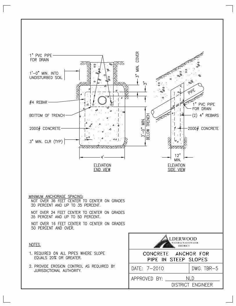
”Criteria for Sewage Works Design”. All sewer main end runs shall be 0.010 ft/ft slope or greater if no further extension is needed or planned. Sewer main slope through easements shall be 0.010 ft/ft unless approved by the District. Slopes greater than 0.20 ft/ft shall be anchored as shown in Division 7 Standard Detail TBR-5.
B. Ductile Iron Pipe: The pipe and fittings shall be inspected for defects before installation. All
lumps, blisters and excess coating shall be removed from the bell and spigot ends of each pipe, the outside of the spigot and the inside of the bell shall be wire-brushed and wiped clean and dry, and be free from oil and grease before the pipe is laid. All pipe coatings shall be checked prior to being laid. All coatings shall be repaired or the pipe replaced as directed by the District. The cutting of pipe for inserting fittings or closure pieces shall be done in a neat and workmanlike manner, without damage to the pipe or coating and so as to leave a smooth end at right angles to the axis of the pipe. Pipe shall be laid with bell ends facing in the direction of the laying. For connection of mechanical joints, the socket, plain end of each pipe and gasket shall be cleaned of dirt before joining, and shall be joined according to manufacturer's directions. Bolts shall be tightened alternately at top, bottom and sides, so pressure on gasket is even.
C. PVC Pipe and Fittings, SDR 35 and C-900/905: Care shall be taken to properly align, clean and lubricate the spigot and socket area of the pipe before joining. The pipe spigot shall be forced into the socket until the reference mark on the spigot is flush with the bell end. Forcing the pipes together beyond this point prevents proper contraction and expansion at the joints. The cutting of pipe for inserting fittings or closure pieces shall be done in a neat and workmanlike manner without damage to the pipe. All connections to an existing sewer pipe or different materials from PVC shall be made with sleeves or adapters which are specifically manufactured for this purpose, and shall use elastomeric gasket joints, unless otherwise specifically authorized by the District.
D. HDPE, See Division 6 for pipe installation. Follow specifications for fusing, and reaming when applied to open cut installation.
E. Aggregate, Trenching, Backfill and Restoration: See Division 7.
F. Trench Dams: See Division 7. G. Installation on Steep Slopes: See Division 7 Standard Detail TBR-5.
Alderwood Water & Wastewater District Effective date 5/6/2013 Development Standards Division 3 – Sewer Installation Page 7 of 12
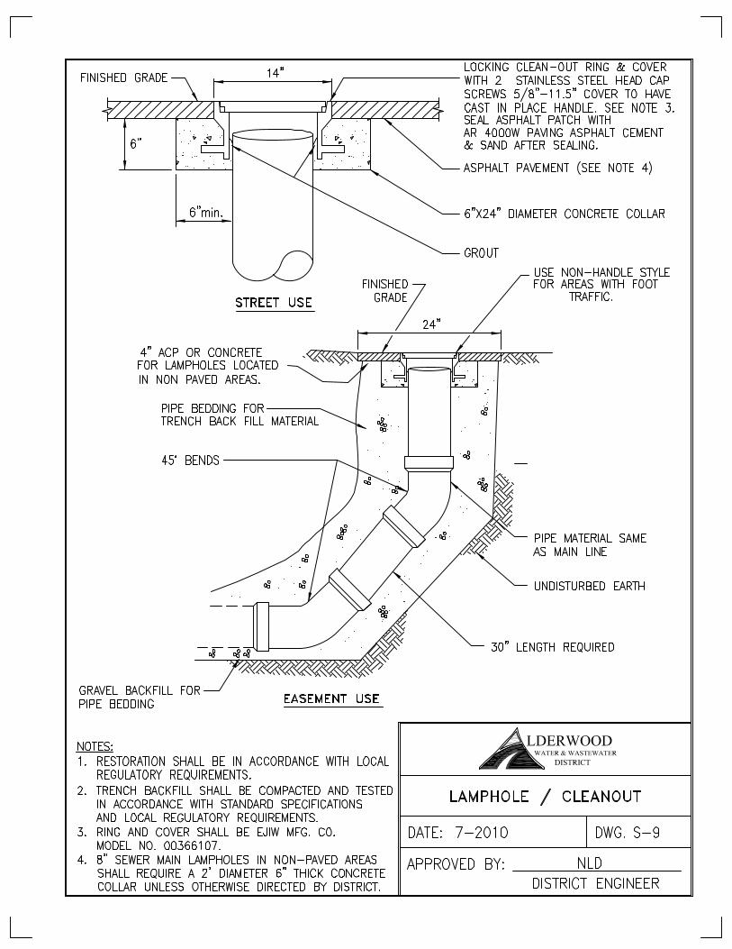
3-2.040 Lampholes A. Materials
Lampholes shall be the same material as the sewer pipe. For lamphole frame and cover, see Standard Detail S-9. Lamphole frames and covers shall be made from superior quality cast iron. The iron shall be of such character as to make castings that will be tough, strong, sound and of even grain and shall conform to the requirements of ASTM Designation A48, Class 30. Lamphole frames and covers shall be of uniform quality, free from blow holes, porosity, shrinkage, distortion, cavities, cracks or other defects. They shall be smooth and well cleaned and continuously machined to prevent rocking and rattling. Welded or caulked repairs shall not be permitted. Covers shall be easily removable.
B. Installation Install lampholes as shown on the Construction Drawings and in accordance with Division 3 and Standard Detail S-9. Lampholes shall only be installed on sanitary sewer runs less than 150 feet where the main will be extended in the future or as directed by the District Lamphole rings and covers shall be set carefully to the lamphole cover grade in a full bed of cement grout. The lamphole cover elevation shall be set flush with the existing pavement or grade in paved and improved areas. In unimproved areas, lamphole cover elevations shall be set two (2) inches above grade unless otherwise shown on the Construction Drawings to be set higher. Install lamphole marker posts on easements and offsite construction in areas where lampholes are located outside of paved areas. Lamphole marker posts shall be composite fiberglass maker posts as manufactured by Hansen Supply (Green 66 inch Hansen Tri-Flex, TF-66-06) or equal and shall be clearly marked "Sewer". Lampholes located outside of paved areas but which are subject to traffic loads shall be constructed in accordance with Division 3 Standard Detail. S-9.
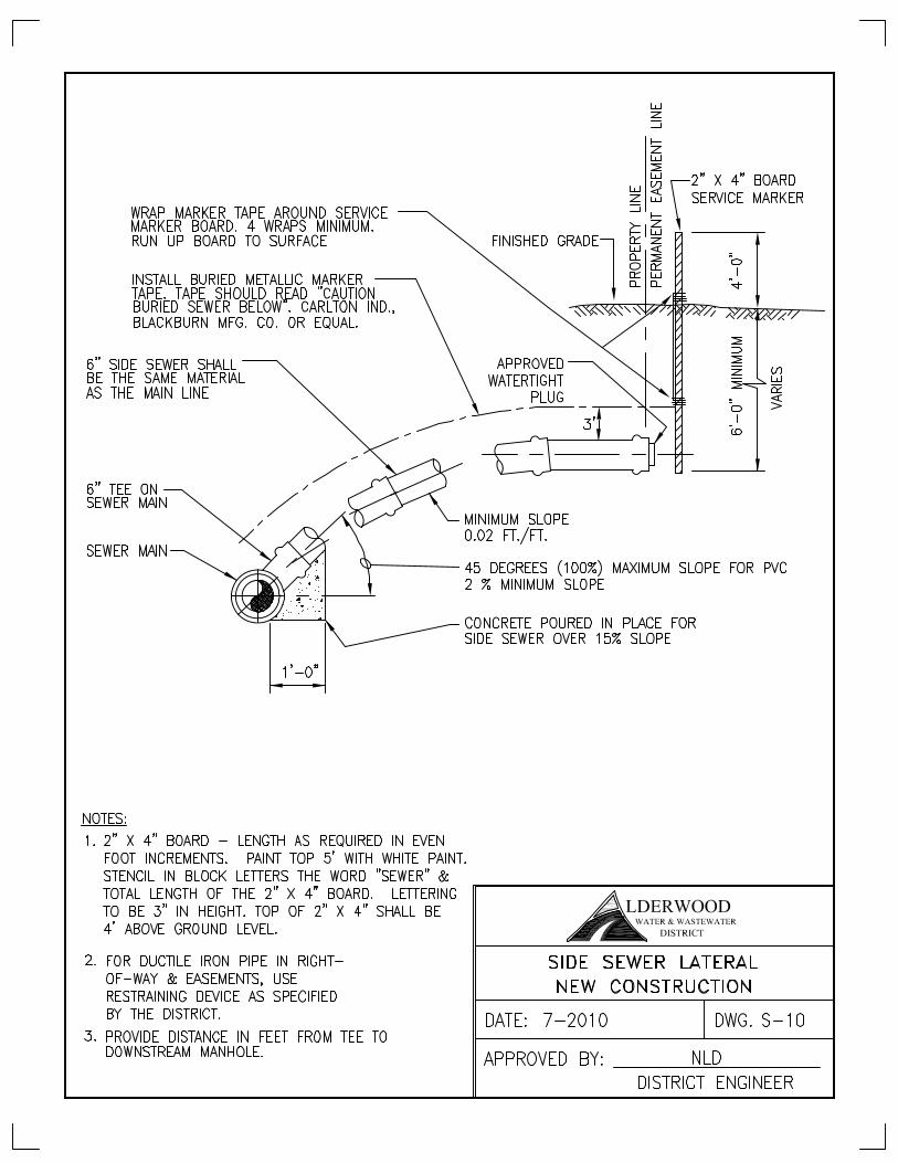
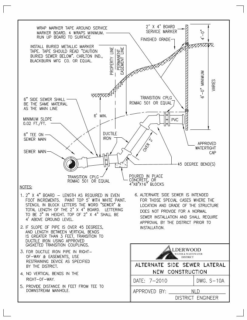
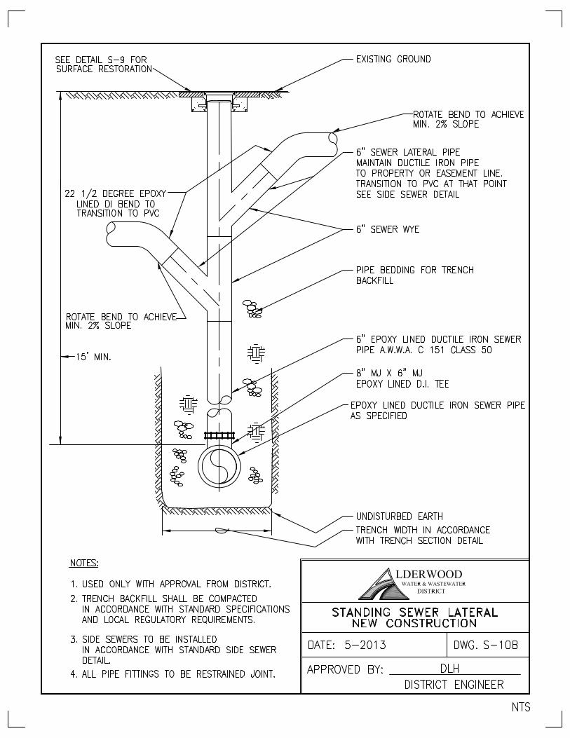
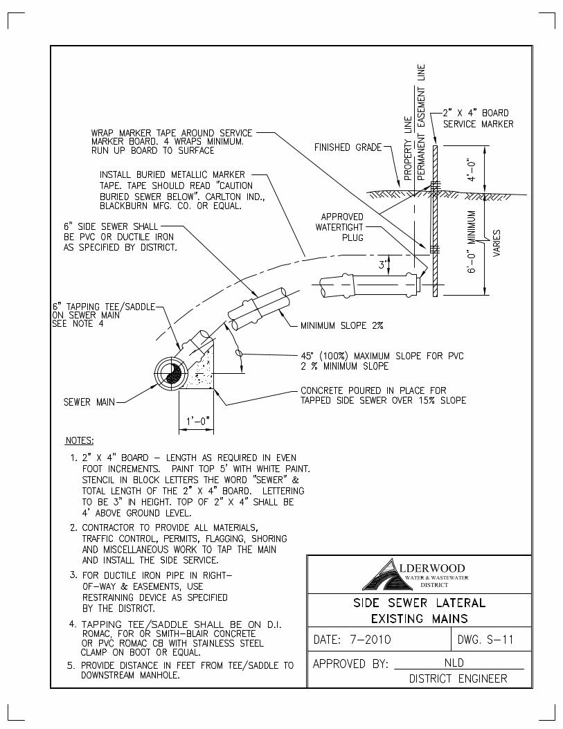
3-2.050 Sewer Laterals All sewer laterals shall be a minimum of 6 inches in diameter and be extended to the property line/edge of easement or the dry utilities whichever is furthest. Install a cap with gasket at end point as shown in Division 3 Standard Detail S-10. The depth of each sewer lateral shall be indicated in the field by the Contractor using 2-inch black stenciled numerals on a white 2–inch by 4-inch marker post. In general, the lateral shall be a minimum depth of 6-feet at the property line. No vertical or horizontal bends shall be allowed in the public right-of-way or sewer easement without specific approval by the District. Side sewers outside the public right-of-way or public easement shall be the responsibility of the property owner to maintain.
Alderwood Water & Wastewater District Effective date 5/6/2013 Development Standards Division 3 – Sewer Installation Page 8 of 12
Measurement from the downstream manhole to each lateral shall be shown on the record drawings See Division 5 for installation of a side sewer outside the public right-of-way or public easement and installation for connecting side sewers to existing laterals. 3-2.060 Precast Concrete Manholes A. Materials
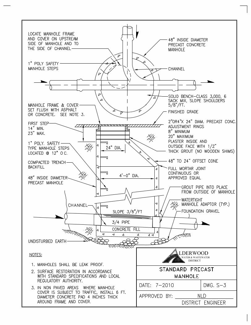
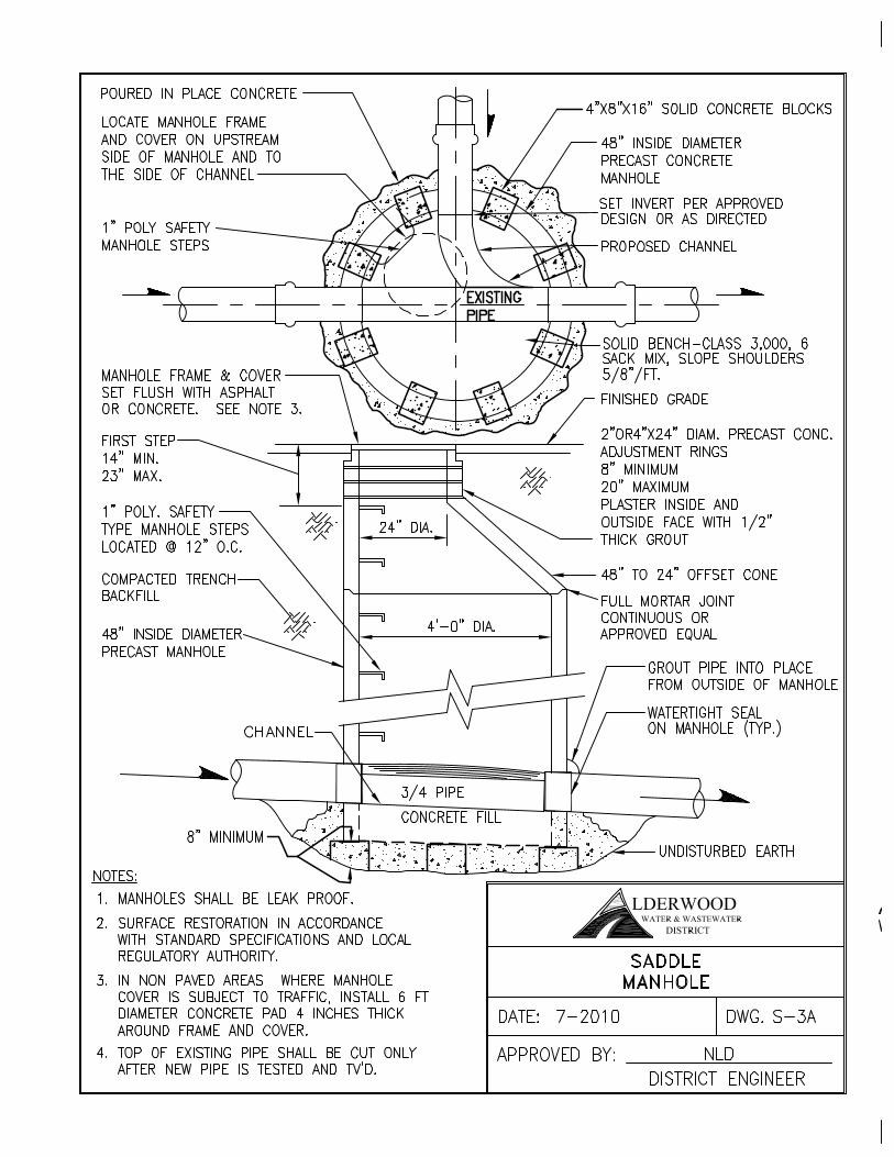
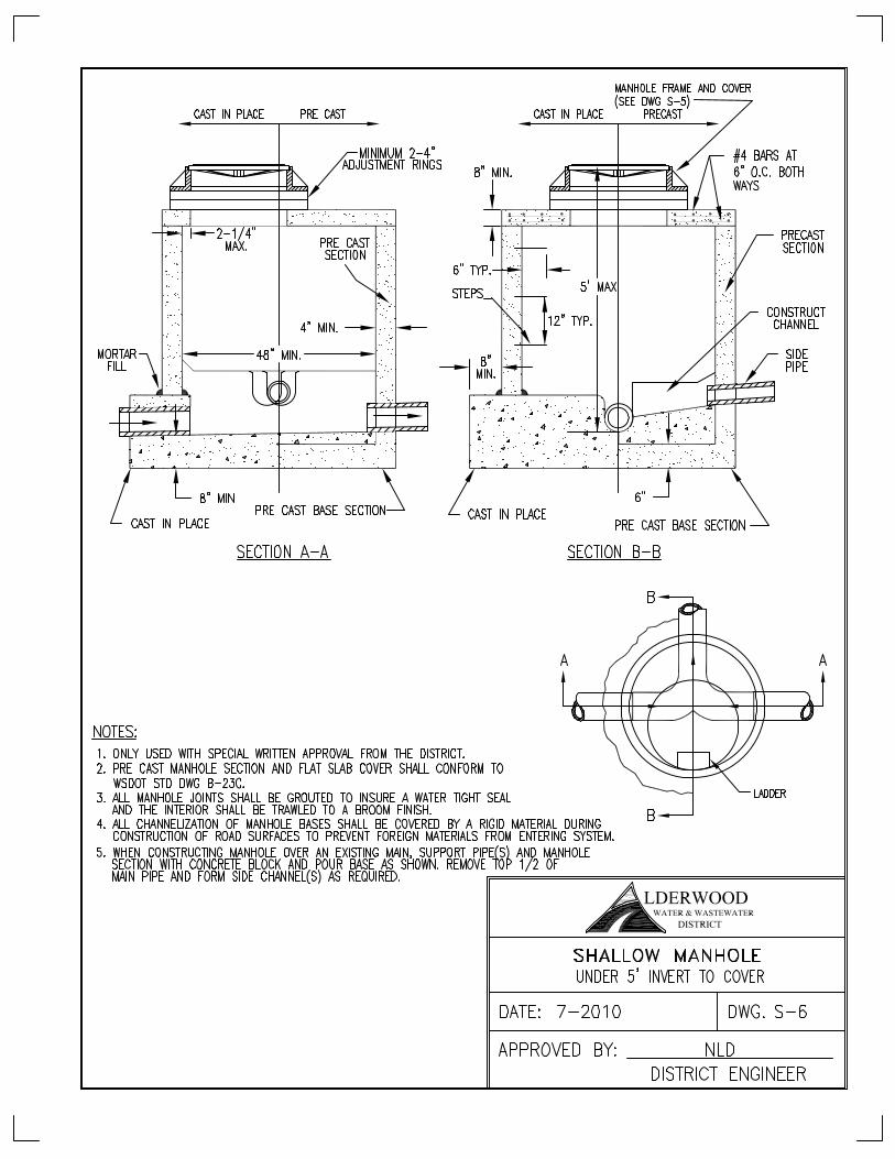
1. Precast manhole components shall conform to the requirements of ASTM Designation C478. All Portland Cement used in the manufacture of the precast sections shall conform to the requirements of ASTM Designation C150, Type II or Type V unless otherwise approved by the District. Standard manhole depth is between 5 feet and 19 feet. Depths less than or greater than the standard depth shall be as approved by the District.
Precast base sections shall conform to the requirements for precast riser section. The base shall be a minimum six (6) inches thick under the pipe invert. Openings for pipes shall be circular, tapered toward the inside of the section, and shall be of the minimum size possible to accommodate the pipe to be inserted and effectively seal the joint.
Standard precast riser sections shall consist of circular sections in standard nominal inside diameter of 48 inches and shall be in accordance with ASTM C478. Minimum height of a riser section shall be one (1) foot. The base sections and risers shall be arranged so no pipes pass through manhole joints. The taper section (cone) shall be eccentric, tapering from 48-inches inside diameter to 24-inches inside diameter. Joining to the riser sections shall be similar to joining between riser sections, but the top surface shall be flat and at least 5-inches wide radially to receive grade rings. Grade rings above the taper section shall be 24-inches inside diameter and 2- or 4- inches high. Grade ring combined height shall be a minimum of 8 inches and shall be a maximum of 20-inches.
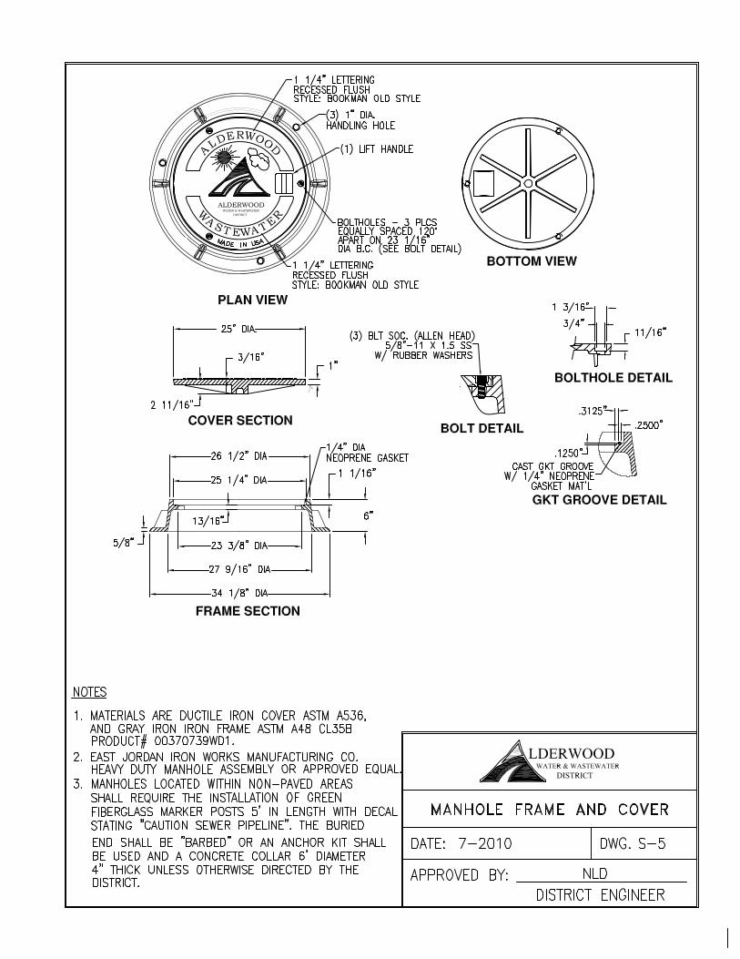
2. Manhole frames and covers shall be made from superior quality cast or ductile iron. The
iron shall be of such character as to make castings that Shall be tough, strong, sound and of even grain and shall conform to the requirements of ASTM A48, Class 30. Manhole frames and covers shall be of uniform quality, free from blow holes, porosity, shrinkage, distortion, cavities, cracks or other defects. They shall be smooth and well cleaned and continuously machined to prevent rocking and rattling. Welded or caulked repairs shall not be permitted. Covers shall be easily removable and shall be interchangeable. Frame and cover shall be in accordance to Division 3 Standard Detail S-5. The manufacturer's name shall be cast into and not stamped on an exposed surface.
3. Water tight seals shall be provided in areas where the manhole lid may be inundated with
water or where odor is a concern. Provide and install ¾” strip of Conseal CD-101 manhole ring and cover sealant on the frame immediately under the manhole lid and bolt
Alderwood Water & Wastewater District Effective date 5/6/2013 Development Standards Division 3 – Sewer Installation Page 9 of 12
the lid down.
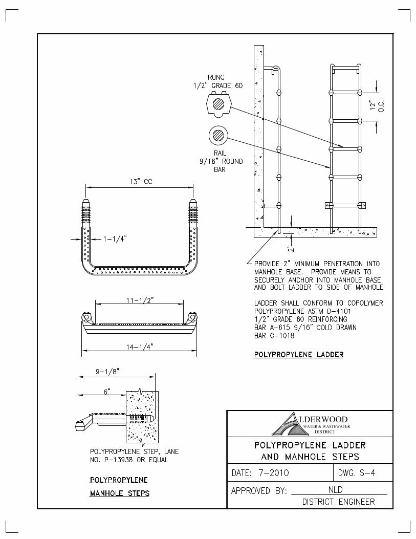
4. Polypropylene manhole steps shall be made of a copolymer polypropylene superior in its resistance to corrosiveness, meeting the requirements of ASTM D4101 and shall completely encapsulate a deformed 1/2-inch steel reinforcing rod, conforming to ASTM A615, Grade 60. Steps shall be Lane International Corporation Manhole Step, or equal. Polypropylene steps shall be factory installed in complete accordance with the manufacturer's instructions. This shall be accomplished by pre-drilling two (2) parallel 1-inch holes, 3-3/4-inch deep and 13-inches on center in the cured concrete base, riser and taper sections of the manhole. The insertion ends of the step shall be fully coated with non-shrink epoxy grout then driven into the holes to the prescribed depth. In no case shall the pre-driven hole be allowed to penetrate through the wall of the manhole section.
5. Channels and benches shall be cast using low shrinkage class 3000 concrete with pea gravel or aggregate up to 5/8 inch (max size). Manholes with pre-cast channels conforming to this minimum standard will also be accepted.
B. Installation
Manhole installation shall be as detailed on the Construction Drawings and in accordance with the Standard Details. Precast sections with damaged joint surfaces, cracks, or damage shall not be installed. Precast base sections shall be set on a prepared bedding material. Before the precast base is set in place, the bedding material shall be carefully leveled to provide full bearing for the entire base section. Precast riser sections and cones shall be set using the specified joint sealant or gasket. Priming and preparation of surfaces and installation of jointing material shall be in strict conformance with the manufacturer's instructions. Grade rings shall be set in a full bed of cement grout. All connections to manholes shall be made with manhole adapters providing a transition from the manhole to pipe material and providing a watertight leak proof seal. All voids around manhole adapters shall be thoroughly grouted and sealed inside and outside of the manhole walls and installed in accordance with manufacturer recommendations. Minimum fall across the channel shall be 0.10-foot. Connections to an existing manhole where a suitable stub does not exist shall be core drilled and a water tight boot style adapter installed. Manhole frames shall be set carefully to the established surface grade in a full bed of cement grout. The manhole rim elevation shall be set flush with the existing pavement or finished grade in paved and improved areas. Wood shims are not allowed. In unimproved areas, manhole rim elevations shall be set 2- inches above grade unless otherwise shown on the Construction Drawings to be set higher. Install manhole marker posts on easements and offsite construction in areas where manholes are located outside of paved areas. Manhole marker posts shall be fiberglass marker posts as manufactured by Hansen Supply (Green 66 inch Hansen Tri-Flex, TF-66-06) or equal and shall be clearly marked "Sewer".
Alderwood Water & Wastewater District Effective date 5/6/2013 Development Standards Division 3 – Sewer Installation Page 10 of 12
Manholes located outside of paved areas but which are subject to traffic loads shall be set within a 6-foot diameter by 4-inch thick concrete protective pad. The Contractor shall provide paved vehicular access to all manholes, either within the public right-of-way or within easements, except as approved otherwise by the District. For sanitary sewers, the guiding criteria shall be that the upstream and downstream manholes shall be accessible and within 300 feet of an inaccessible manhole to allow for the clearing of blockages within all lines. Manholes set in paved streets or other paved areas shall adjusted to finished grade after paving and when required, the manhole frame shall be tilted to conform to the slope of the paved surface. Channels shall be given a light broom finish, or equivalent, and channel landings shall be sloped to drain into the channels. Bottom and sides shall be given a trowel finish. Benches shall receive a light broom finish. Unless precast channeled bases are used, notify the District when channeling is scheduled and provide a copy of the concrete mix ticket. Ladders shall be installed in base sections. Steps shall be installed in riser sections and taper sections so that the completed manhole shall have a continuous vertical ladder with equally spaced rungs as shown on the Standard Details. Steps shall be firmly cast or grouted in place. Infiltration around steps shall not be allowed. Manholes shall not be located in curbs and gutter lines or low points. Manholes shall not be located in sidewalks or crosswalks unless otherwise approved by the District. Maximum spacing between manholes is 400 feet. The minimum inside diameter of manholes shall be 48 inches. For incoming pipes larger than 24 inches in diameter, the manhole shall be 54 inches or greater. Manholes with invert elevations greater than or equal to 19 feet below finished grade shall be a minimum 60 inches in diameter. Manholes are mandatory when connecting significant commercial or industrial facilities to the sanitary sewer system and shall be of adequate size to provide for monitoring and sampling equipment.
3-3.000 TESTING A. General
Prior to testing, the Contractor shall flush and thoroughly clean all lines. All dirt, sand and other debris shall be completely removed. In addition to the requirements for testing the sewer pipe, all lines shall be visually free from leakage. If the pipe installation fails to meet these requirements, the Contractor shall determine, at his own expense, the source or sources of leakage and shall repair (if the extent and type of repairs proposed by the Contractor appear reasonable to the District) or
Alderwood Water & Wastewater District Effective date 5/6/2013 Development Standards Division 3 – Sewer Installation Page 11 of 12
replace all defective materials or workmanship. The completed pipe installation shall meet the requirements of the visual test, and shall meet the requirements of the air test or the alternative water exfiltration test before District acceptance. If deemed necessary by the District, the first section of pipe installed, at least 100 feet in length, installed by the each crew, shall be tested, in order to qualify the crew and/or the material. A successful installation of this first section shall be a prerequisite to further pipe installation by the crew. At the Contractor's option, testing may be performed at any time during the construction process after at least two 2 feet of backfill has been placed over the pipe. The District shall require testing after backfilling is complete.
B. Television Inspection
All videos shall be provided on DVD format. The video camera shall have a swivel head lens capable of turning and rotating 180 degrees to provide inspection of side sewer connections. The camera shall have a 1-inch ball placed immediately in front of the camera mounted such that the ball contacts the pipe bottom at all times. Television inspections shall be conducted following trench backfill; compaction, and cleaning, after all manholes are channeled, invert elevations, and record drawings are received, reviewed and accepted by the District. Water shall be poured into the system immediately preceding the television inspection and shall be visible on the DVD recording. The District shall be notified two working days prior to any televised inspection. All lines not clean shall be re-flushed, cleaned and re-videoed. The Contractor shall provide to the District a DVD with a separate written report for each sewer line segment.
C. Air Testing
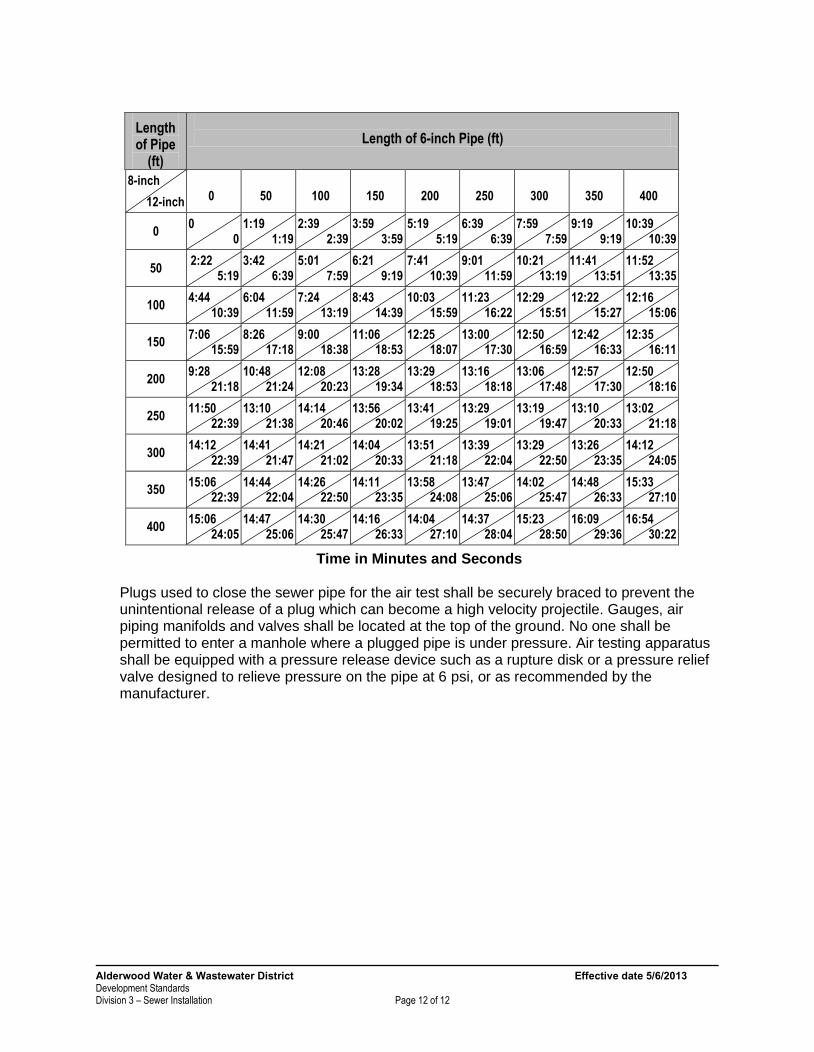
In areas where other underground utilities will be installed, (power, communications, gas, etc.) that may conflict with the sewer installation, the District shall witness the air test after those utilities are installed. The Contractor may choose to pre-test their lines prior to this. The pipe installation shall be tested with low pressure air. Air shall be slowly supplied to the plugged pipe installation until the internal air pressure reaches 4.0 pounds per square inch greater than the average back pressure of any ground water that may submerge the pipe. At least two minutes shall be allowed for temperature stabilization before proceeding further. The time interval required for the internal pressure to decrease from 4.0 to 3.0 pounds per square inch must be equal to or greater than the time that is indicated on the following table:
Alderwood Water & Wastewater District Effective date 5/6/2013 Development Standards Division 3 – Sewer Installation Page 12 of 12
Length of Pipe
(ft)
Length of 6-inch Pipe (ft)
8-inch
12-inch
0
50
100
150
200
250
300
350
400
0 0
0 1:19
1:19 2:39
2:39 3:59
3:59 5:19
5:19 6:39
6:39 7:59
7:59 9:19
9:19 10:39
10:39
50 2:22
5:19 3:42
6:39 5:01
7:59 6:21
9:19 7:41
10:39 9:01
11:59 10:21
13:19 11:41
13:51 11:52
13:35
100 4:44
10:39 6:04
11:59 7:24
13:19 8:43
14:39 10:03
15:59 11:23
16:22 12:29
15:51 12:22
15:27 12:16
15:06
150 7:06
15:59 8:26
17:18 9:00
18:38 11:06
18:53 12:25
18:07 13:00
17:30 12:50
16:59 12:42
16:33 12:35
16:11
200 9:28
21:18 10:48
21:24 12:08
20:23 13:28
19:34 13:29
18:53 13:16
18:18 13:06
17:48 12:57
17:30 12:50
18:16
250 11:50
22:39 13:10
21:38 14:14
20:46 13:56
20:02 13:41
19:25 13:29
19:01 13:19
19:47 13:10
20:33 13:02
21:18
300 14:12
22:39 14:41
21:47 14:21
21:02 14:04
20:33 13:51
21:18 13:39
22:04 13:29
22:50 13:26
23:35 14:12
24:05
350 15:06
22:39 14:44
22:04 14:26
22:50 14:11
23:35 13:58
24:08 13:47
25:06 14:02
25:47 14:48
26:33 15:33
27:10
400 15:06
24:05 14:47
25:06 14:30
25:47 14:16
26:33 14:04
27:10 14:37
28:04 15:23
28:50 16:09
29:36 16:54
30:22
Time in Minutes and Seconds Plugs used to close the sewer pipe for the air test shall be securely braced to prevent the unintentional release of a plug which can become a high velocity projectile. Gauges, air piping manifolds and valves shall be located at the top of the ground. No one shall be permitted to enter a manhole where a plugged pipe is under pressure. Air testing apparatus shall be equipped with a pressure release device such as a rupture disk or a pressure relief valve designed to relieve pressure on the pipe at 6 psi, or as recommended by the manufacturer.


Alderwood Water & Wastewater District Effective Date 5/6/ 2013 Development Standards Division 5 – Side Sewer Installation Page 1 of 9
DIVISION 5
Standards
for
Side Sewer Installation
Alderwood Water & Wastewater District Effective Date 5/6/ 2013 Development Standards Division 5 – Side Sewer Installation Page 2 of 9
Division 5
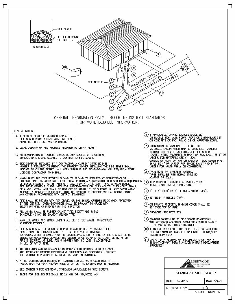
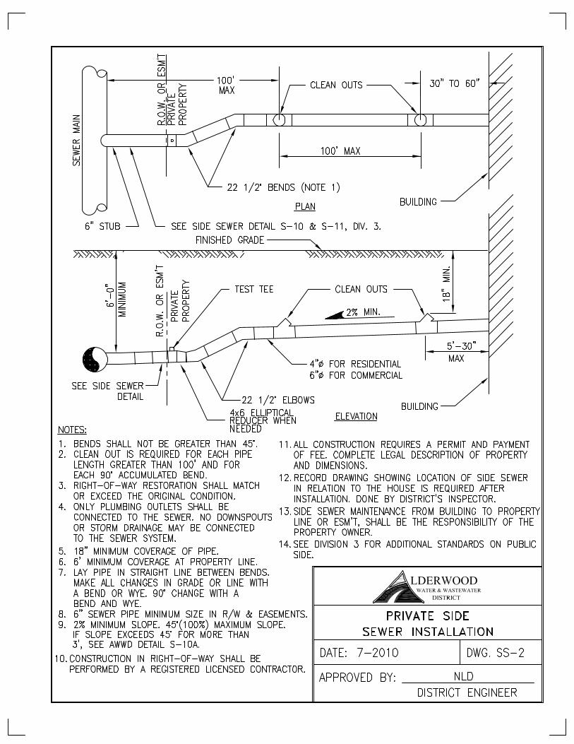
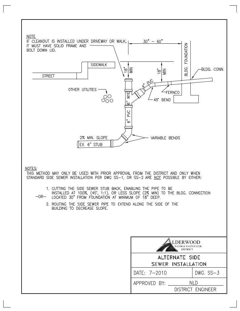
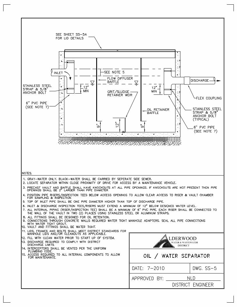
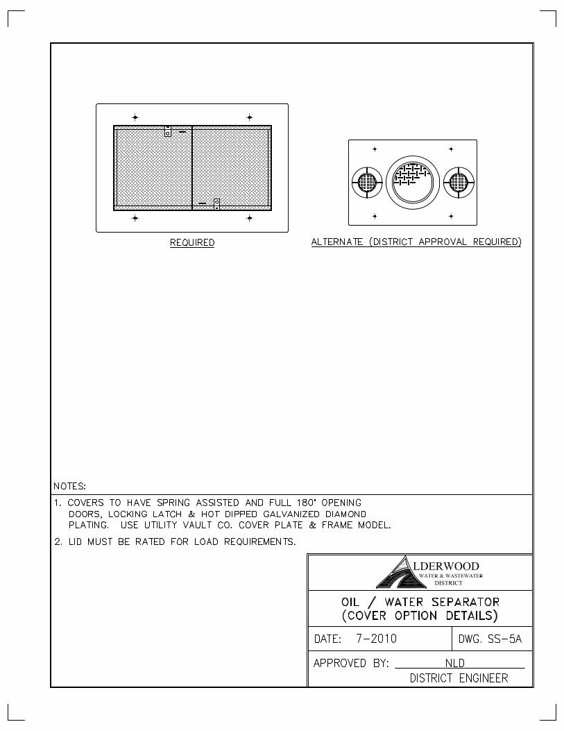
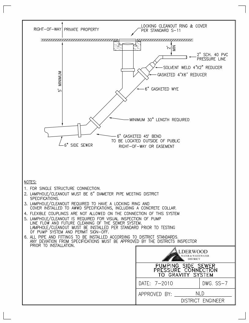
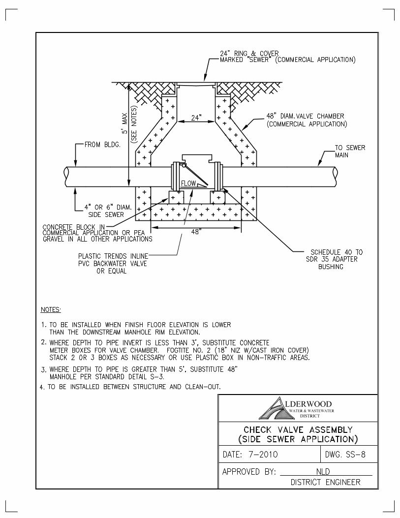
Standards for Side Sewer Installation Table of Contents 5-1.000 SIDE SEWERS ...........…………………………………………..…............................….3 5-1.010 General……………...………………………………………………………………………..3 5-1.020 Permits………………………………………………………………………………………..3 5-2.000 CONSTRUCTION STANDARDS.…………………………………………………………4 5-2.010 General…………………………………………………………………………………….....4 5-2.020 Materials……………………………………………………………………………………...4 5-2.030 Size…………………………………………………………………………………………....6 5-3.000 INSTALLATION……………………………………………………………………………..6 5-3.010 General…………………………………………………………………………………….....6 5-3.015 Tapping and Abandon/Capping…………………………………………………………....7 5-3.020 Trench Excavation……………………………………………………..…………………....7 5-3.030 Pipe Installation……………………………………………………………………………...8 5-3.040 Inspection………………………………………………………………………………….....9 DETAILS Standard Side Sewer........................................................................................................... SS-1 Private Side Sewer Installation............................................................................................ SS-2 Alternate Private Side Sewer Installation.......................................................................... SS-3 Grease Interceptor............................................................................................................... SS-4 Oil/Water Separator............................................................................................................. SS-5 Oil/Water Separator (Cover Options Details)...................................................................... SS-5A Open.................................................................................................................................... SS-6 Pumping Side Sewer Pressure Connection to Gravity Sewer............................................. SS-7 Check Valve Assembly (Side Sewer Application)................................................................ SS-8
Alderwood Water & Wastewater District Effective Date 5/6/ 2013 Development Standards Division 5 – Side Sewer Installation Page 3 of 9
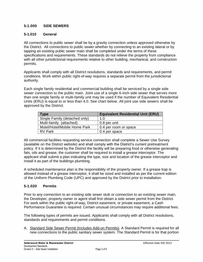
5-1.000 SIDE SEWERS 5-1.010 General All connections to public sewer shall be by a gravity connection unless approved otherwise by the District. All connections to public sewer whether by connecting to an existing lateral or by tapping an existing public sewer main shall be completed under the terms of these specifications and requirements. These standards do not relieve the property from compliance with all other jurisdictional requirements relative to other building, mechanical, and construction permits. Applicants shall comply with all District resolutions, standards and requirements, and permit conditions. Work within public right-of-way requires a separate permit from the jurisdictional authority. Each single family residential and commercial building shall be serviced by a single side sewer connection to the public main. Joint use of a single 6-inch side sewer that serves more than one single family or multi-family unit may be used if the number of Equivalent Residential Units (ERU) is equal to or less than 4.0. See chart below. All joint use side sewers shall be approved by the District.
Type Equivalent Residential Unit (ERU)
Single Family (detached only) 1.0
Multi-family (attached) 0.8 per unit
Motel/Hotel/Mobile Home Park 0.4 per room or space
RV Park 0.4 per space
All commercial facilities requesting service connection shall complete a Sewer Use Survey (available on the District website) and shall comply with the District’s current pretreatment policy. If it is determined by the District the facility will be preparing food or otherwise generating fats, oils and grease, the customer shall be required to install a grease interceptor. The applicant shall submit a plan indicating the type, size and location of the grease interceptor and install it as part of the buildings plumbing. A scheduled maintenance plan is the responsibility of the property owner. If a grease trap is allowed instead of a grease interceptor, it shall be sized and installed as per the current edition of the Uniform Plumbing Code (UPC) and approved by the District prior to installation. 5-1.020 Permits Prior to any connection to an existing side sewer stub or connection to an existing sewer main, the Developer, property owner or agent shall first obtain a side sewer permit from the District. For work within the public right-of-way, District easement, or private easement, a Cash Performance Guarantee is required. Certain unusual circumstances may require additional fees. The following types of permits are issued. Applicants shall comply with all District resolutions, standards and requirements and permit conditions. A. Standard Side Sewer Permit (Includes Add-on Permits). A Standard Permit is required for all
new connections to the public sanitary sewer system. The Standard Permit is for that portion
Alderwood Water & Wastewater District Effective Date 5/6/ 2013 Development Standards Division 5 – Side Sewer Installation Page 4 of 9
of the side sewer beginning 2-feet from the building or structure and continuing to the connection to the public sanitary sewer system. The building sewer which includes all interior plumbing and continues to 2-feet outside of the building or structure is considered part of the building, plumbing and/or construction permits.
B. Dry Side Sewer Permit. A Dry Permit may be available for purchase in certain situations when a property, building or structure is not ready for construction and/or connections to the public sanitary sewer facility, but it is desirable to install a portion of the side sewer from the sewer system to a point within the property, but is not connected to any sewer user. This is called a “dry side sewer”.
The District will determine when a Dry Side Sewer Permit is may be used.
A separate permit shall be required to make the final connection to the building or sewer user.
C. Revision Side Sewer Permit. A Revision Permit is required when a property has existing
sanitary sewer service but is proposing a revision to the service outside of the building or structure. This may be the result of adding additional buildings or structures, or remodeling existing buildings or structures. The District will determine when a Side Sewer Revision Side Sewer Permit is applicable.
D. Capping Side Sewer Permit. A Capping Permit is required when side sewer service is being discontinued or is abandoned. The sewer lateral shall be cut and capped at the main line unless otherwise determined by the District.
5-2.000 CONSTRUCTION STANDARDS 5-2.010 General Side sewer installation shall be in accordance with the latest edition of the Uniform Plumbing Code as modified by these standards. The intent of these District Side Sewer Standards is to reasonably ensure that properties connecting to the District's system have a good quality private sewer service connection to the District's public sewer system. While the District has established standards and conducts installation inspections, the ultimate responsibility for all private side sewers rests with the property owner. For work within public right-of-way, all requirements of the right-of-way permit shall be met. 5-2.020 Materials A. Pipe: All materials shall be manufactured of premium quality materials and shall conform
to all approved applicable standards, shall be free of all defects and shall pass all required testing.
Alderwood Water & Wastewater District Effective Date 5/6/ 2013 Development Standards Division 5 – Side Sewer Installation Page 5 of 9
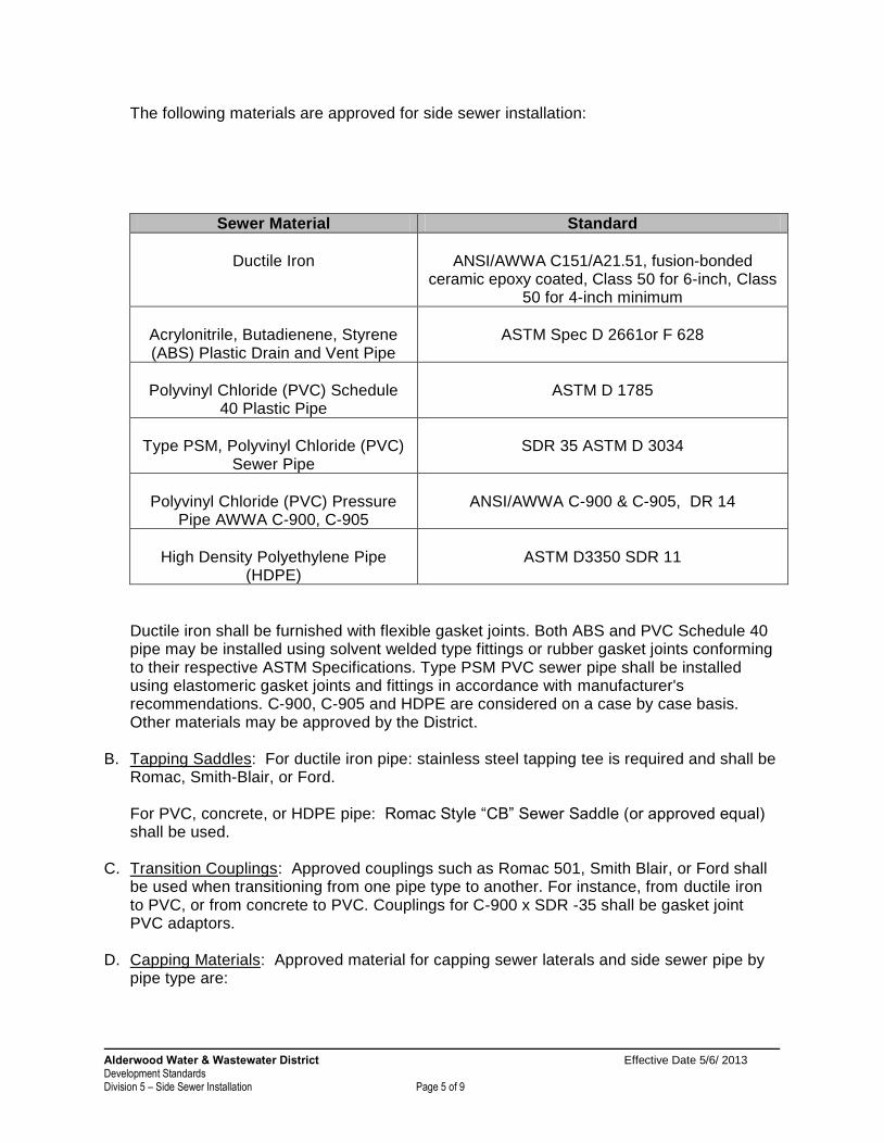
The following materials are approved for side sewer installation:
Sewer Material Standard
Ductile Iron
ANSI/AWWA C151/A21.51, fusion-bonded
ceramic epoxy coated, Class 50 for 6-inch, Class 50 for 4-inch minimum
Acrylonitrile, Butadienene, Styrene (ABS) Plastic Drain and Vent Pipe
ASTM Spec D 2661or F 628
Polyvinyl Chloride (PVC) Schedule
40 Plastic Pipe
ASTM D 1785
Type PSM, Polyvinyl Chloride (PVC)
Sewer Pipe
SDR 35 ASTM D 3034
Polyvinyl Chloride (PVC) Pressure
Pipe AWWA C-900, C-905
ANSI/AWWA C-900 & C-905, DR 14
High Density Polyethylene Pipe
(HDPE)
ASTM D3350 SDR 11
Ductile iron shall be furnished with flexible gasket joints. Both ABS and PVC Schedule 40
pipe may be installed using solvent welded type fittings or rubber gasket joints conforming to their respective ASTM Specifications. Type PSM PVC sewer pipe shall be installed using elastomeric gasket joints and fittings in accordance with manufacturer's recommendations. C-900, C-905 and HDPE are considered on a case by case basis. Other materials may be approved by the District.
B. Tapping Saddles: For ductile iron pipe: stainless steel tapping tee is required and shall be
Romac, Smith-Blair, or Ford. For PVC, concrete, or HDPE pipe: Romac Style “CB” Sewer Saddle (or approved equal) shall be used. C. Transition Couplings: Approved couplings such as Romac 501, Smith Blair, or Ford shall
be used when transitioning from one pipe type to another. For instance, from ductile iron to PVC, or from concrete to PVC. Couplings for C-900 x SDR -35 shall be gasket joint PVC adaptors.
D. Capping Materials: Approved material for capping sewer laterals and side sewer pipe by pipe type are:
Alderwood Water & Wastewater District Effective Date 5/6/ 2013 Development Standards Division 5 – Side Sewer Installation Page 6 of 9
Concrete pipe: a mechanical pressure plugs manufactured by Taylor Made Plastics or approved equal shall be sized to fit in the bell of the existing tee, larger than the 6-inch I.D.
PVC pipe: a PVC cap or spigot plug with rubber gasket.
Ductile iron pipe: a MJ plug. 5-2.030 Size The portions of sewer laterals in right-of-way and easements shall be 6-inches minimum. The side sewer may be 4-inches for single family residences once outside of right-of-ways or easements. Side sewer for single family residences shall be no less than 4-inches. Side sewers for commercial and multi-family shall be no less than 6-inch. All commercial buildings shall have a separate sewer stub for each separate building. Side sewers for duplex units shall be no less than 4-inches when an individual service connection is used. If served by a single stub, the stub shall be a minimum 6-inch where the line is used jointly with a separate 4-inch service to each side. If one connection to the duplex is used, a minimum 6-inch is required. Side sewers for single family residences approved by the District for a joint use side sewer shall be a minimum 6-inch in areas of common use. 5-3.000 INSTALLATION 5-3.010 General Side sewer installation shall be in accordance with the latest edition of the Uniform Plumbing Code as modified by the District and these specifications and details. Only properly insured general contractors or utility contractors licensed and bonded with the State of Washington shall perform side sewer installations within the public right-of-way or within private easements. A copy of the license shall be provided to the District. Nothing contained in side sewer permit shall create any contractual rights between the District and any person or firm employed to do the Work. If the property owner desires to perform the work themselves on their property, the property owner shall indicate this on the application form and shall comply with District Standards. The pipe and jointing materials for the sewer lateral along with the manner in which they are installed, shall be of the same style and materials as the main to which they are connecting. If not connecting to the building or structure, each sewer lateral and side sewer shall be capped and blocked in accordance with the Standard Details.
Alderwood Water & Wastewater District Effective Date 5/6/ 2013 Development Standards Division 5 – Side Sewer Installation Page 7 of 9
On private side sewers, cleanouts are required every 100 feet, at 90 degree bends, or combinations of bends greater than 45 degrees. No vertical or horizontal bends shall be allowed in the public right-of-way or sewer easement without specific authorization by the District. See Division 3 for other standards and details applicable to this section. 5-3.015 Tapping and Abandoning/Capping When excavating around existing sewer mains, great care shall be taken to not damage the existing sewer line. When the sewer lateral installation requires the tapping of an existing District sewer mainline or capping of an existing side sewer or lateral, the materials shall be provided by the Contractor. The Contractor shall be responsible to provide all equipment, staff (including certified flagger(s) if needed), excavation, approved shoring, ladder, dewatering, backfilling, compacting, restoration and materials to assist District forces in tapping existing sewer line or witnessing the capping. A. Tapping. The Contractor shall schedule District forces a minimum of three (3) business
days in advance. Taps shall be scheduled for Tuesday, Wednesday, or Thursdays. The Contractor prepares the trench in accordance with all safety standards and provides 1-foot distance around the existing sewer main. Shoring shall not be supported by the mainline. District forces will install the tapping tee provided by the Contractor and make the tap. The Contractor shall install the pipe from the tapping tee to the property.
B. Abandoning/Capping. The Contractor shall excavate the existing tee on the mainline and
plugs or caps the existing tee. 1. For existing concrete lines: A mechanical plug sized to fit the existing bell but larger than
6-inch inside diameter is used. See section 5-2.020 for type. The plug is inserted and grouted. Abandoned piping is grout plugged or if directed by the District, filled with flowable Control Density Fill (CDF).
2. For existing PVC lines, a spigot PVC plug shall be inserted into the existing tee or a PVC cap with rubber gasket placed on pipe within 1 foot of mainline. Inspection is required prior to backfill.
3. For existing ductile iron lines, a MJ plug shall be installed with gasket and bolts on the tee.
4. Inspection is required on capping of sewers laterals prior to backfill.
5-3.020 Trench Excavation Trench excavation shall be accomplished with suitable equipment to provide the minimum lines and grades required. All excavations shall comply with applicable Federal, State and local regulations. The Contractor shall be responsible for all trench safety requirements. Over-excavation of trenches shall be brought back to required grade by installation of select backfill material and compacted to 95% of maximum density or as directed by the District. Unsuitable materials, such as peat, clay and muck, shall be removed to at least two feet below grade or as directed by the District, and replaced with select backfill material capable of being compacted to 95% maximum density as directed by the District. Trench excavations shall achieve the following results:
Alderwood Water & Wastewater District Effective Date 5/6/ 2013 Development Standards Division 5 – Side Sewer Installation Page 8 of 9
Be neat, clean and straight between bends.
Be of proper grade, minimum 2 percent and maximum 45 degrees (100 percent).
Utilize method of pipe supporting acceptable to the District and evaluate other options, such as increasing the pipe run to allow for flatter slopes, prior to the District allowing pipe grades in excess of 45 degrees (100 percent).
Slopes in excess of 45 degrees (100 percent) shall require special blocking and lateral supports and may require an increased standard of pipe i.e. ductile iron.
Be constructed and left in a safe manner in accordance with appropriate regulatory authorities.
Properly coordinated with the sewer lateral and/or side sewer installation and inspection so as to minimize the time trenches are open.
Promptly backfilled upon approval of pipe installation. 5-3.030 Pipe Installation Pipe Installation shall proceed in conjunction with trench excavation. Pipe installation shall be in accordance with the Uniform Plumbing Code as modified by these standards. Minimum grade is 2 percent. Special circumstances may require consideration of grades less than 2 percent, but all such cases require prior approval by the District. Maximum grade is 45 degrees (100 percent). Grades in excess of 45 degrees (100 percent) shall be considered subject to special restraining in accordance with the standard details. All side sewers shall be bedded with pea gravel, or with prior approval by the District, 5/8 minus crushed rock may be used. Cleanouts shall be required and installed as follows:
At the building connection, as directed by the District.
No less than every 100-feet.
At all changes in directions in excess of 45 degrees. If combinations of bends have straight pipe runs of 4-feet or greater between bends, that shall not be considered an aggregate change of direction.
If directed by District, a change of direction (total of bends) exceeds a total of 135 degrees
Installed to allow for cleaning in the direction of flow.
Cleanouts installed in roads, driveways or walkways, paved or unpaved, shall have a frame and cover installed in accordance with Division 3 of these standards.
No connections from downspouts, gutters, footing drains or outside drains or any other feature receiving or exposed to rain or ground water shall be allowed to sewers. Side sewers shall be a minimum of 18-inches deep at 2-feet from the outside foundation wall or structure. Suitable grade transitions (fittings) shall be installed between the structure and the side sewer to achieve the desired depth.
Alderwood Water & Wastewater District Effective Date 5/6/ 2013 Development Standards Division 5 – Side Sewer Installation Page 9 of 9
5-3.040 Inspection All side sewers shall be tested and inspected by the District prior to backfilling. Any work that has been covered and which the District did not inspect shall be uncovered to allow for inspections and testing. A. Advance Notice. It is the responsibility of the person authorized by the permit to perform
the work to provide notice to the District that the work is ready for inspection. Such notice shall be at least one business day before the desired inspection date. The District will schedule the inspection as near the desired time as possible subject to the District’s availability.
B. Responsibility. It shall be the responsibility of the person authorized by the permit to
ensure the side sewer is complete and shall stand all prescribed tests prior to the desired inspection date.
C. Tests. After pipe inspection, pipe shall be secured with backfill prior to pressure test. All
tests shall be conducted in the presence of the District. The person authorized to complete the work shall be present during the inspection and testing periods.
Tests shall be made for minimum grade. Visual inspections shall be conducted on all alignment, grade, backfill, and other items the District deems relevant. Water tests shall be completed by plugging the side sewer and filling with water to the point of overflow. The sewer shall be tested in its entirety or in sections as directed by the District. Water shall be kept in the side sewer for a minimum of 15 minutes. The system shall be water tight with no visual or measurable leakage. An alternate to water testing is a standard air pressure test of 4 pounds per square inch of pressure for a 5-minute period with no measurable loss of pressure.
D. Corrections. Notices of corrections or deficiencies shall be given at the time of inspection or
written and delivered to the permittee or their authorized representative. All corrections and/or deficiencies noted by the District shall be corrected prior to
scheduling a re-inspection. E. Re-testing. After all corrections and/or deficiencies noted by the District have been
corrected, the permittee shall again schedule an inspection with the District. Additional corrections and/or deficiencies may be noted at this time.
F. Additional Payment. If a side sewer does not successfully pass an initial and subsequent
re-test, the applicant shall be subject to payment of an additional side sewer permit fee prior to any additional inspections.
G. Approval. Upon the satisfactory testing and upon satisfactory evidence that all interior
plumbing has been approved, the side sewer shall be approved for use and operation by the District and allowed to discharge into the District sewer system.


Alderwood Water & Wastewater District Effective Date 5/6/2013 Development Standards Division 6 – Trenchless Installation Page 1 of 8
DIVISION 6
Standards
for
Trenchless Installation
Alderwood Water & Wastewater District Effective Date 5/6/2013 Development Standards Division 6 – Trenchless Installation Page 2 of 8
Division 6
Standards for Trenchless Installation
Table of Contents 6-1.000 TRENCHLESS INSTALLATION ............................................................................... 3 6-1.010 General ...................................................................................................................... 3 6-1.020 Contractor Qualifications............................................................................................ 3 6-1.030 Trenchless Submittals ............................................................................................... 4 6-1.040 Construction Standards ............................................................................................. 5 6-2.000 MATERIALS .............................................................................................................. 5 6-2.010 General ...................................................................................................................... 5 6-2.020 Casing Pipe ............................................................................................................... 5 6-2.030 Casing Spacers ......................................................................................................... 5 6-2.040 Carrier Pipe ............................................................................................................... 6 6-2.050 Fittings ....................................................................................................................... 6 6-2.060 Drilling Fluid ............................................................................................................... 6 6-3.000 INSTALLATION ........................................................................................................ 7 6-3.010 General ...................................................................................................................... 7 6-3.020 Trenching and Installation .......................................................................................... 7 6-3.030 Testing and Acceptance ............................................................................................ 8 DETAILS Typical Casing Detail.................................................................................................................TI-1
Alderwood Water & Wastewater District Effective Date 5/6/2013 Development Standards Division 6 – Trenchless Installation Page 3 of 8
6-1.000 TRENCHLESS INSTALLATION 6-1.010 General The District may allow the use of trenchless methods to complete portions of water and/or sewer projects and extensions. The use of trenchless methods shall require special approval of the District. Trenchless methods shall only be considered when other standard methods of construction cannot be completed in a reasonable or economical fashion. Any use of trenchless methods shall be at the Contractor's complete risk as to the ability to satisfactorily complete the utility installation in compliance with District standards. Methods the District is willing to consider and evaluate include:
Horizontal Directional Drilling (HDD) Microtunneling Pipe Jacking Pipe Bursting Auger Boring Pipe Ramming
Each of these methods may be suitable for different site conditions, soil types, water table levels and utility size and type. Consideration shall be given to those issues when Contractor is selecting a proposed method. 6-1.020 Contractor Qualifications The Contractor shall demonstrate to the satisfaction of the District that the Contractor is qualified to perform the work. The District reserves the right to contact references and investigate past performance and qualifications of the Contractor. The District may contact references for other projects, including District projects, even though the Contractor did not identify those projects and /or references. Poor references may be justification to determine that the Contractor is not acceptable for the proposed method. The Contractor shall provide references and, at a minimum, the information required by each item set forth below. A. Trenchless Contractor:
Specializes in trenchless installations for a minimum of the last five years.
Completed at least three trenchless projects in the last two years using the type of trenchless system to be used on this Contract.
All trenchless projects that have been constructed in conditions of a similar nature and geology to those indicated in the Drawings including work in granular soils, dealing with frac-out situations, and cleanup and disposing of bentonite.
B. Trenchless Superintendent:
Experience as a superintendent on at least three trenchless projects in the past two years using the type of trenchless system to be used on this Contract.
All projects to have been constructed in conditions of a similar nature and geology to those indicated in the Drawings.
Describe the superintendent’s responsibilities on each project.
Alderwood Water & Wastewater District Effective Date 5/6/2013 Development Standards Division 6 – Trenchless Installation Page 4 of 8
C. Trenchless Operator:
Experience as a trenchless machine operator on at least three trenchless projects in the past two years using the type of trenchless system to be used on this Contract.
All projects that have been constructed in lengths and conditions of a similar nature and geology to those indicated in Drawings.
D. Trenchless Designer:
Registered professional engineer licensed in the State of Washington with a minimum of three years experience in trenchless construction in diameters, lengths and conditions of a similar nature and geology to those indicated in Drawings.
E. Mud Engineer:
Minimum of two years experience with slurry design used in trenchless installations in granular and abrasive soils.
Minimum of two years experience with slurry separation systems and additives to be used for effective soil separation for all soil types and quantities indicated in the Drawings.
F. Biological Monitor:
Fisheries biologist with a minimum of 10 years experience in local sensitive species identification and surveys, experience with fish life status, salmon habitat requirements, and water quality issues.
G. Surveyor:
Surveyor shall be a professional land surveyor who is licensed in the State of Washington.
H. Additional Qualifications:
The District may request additional information to demonstrate that the Contractor is qualified to perform the Work.
6-1.030 Trenchless Submittals Contractor shall provide the District with a trenchless submittal that shall include at a minimum: A. Trenchless system plan for each drive. Resubmit for all modifications to that previously
accepted. Certifications that pits are constructed as required and certified for trenchless operations.
B. Reports and records: 1. Alignment surveys and checks: prior, during, and at completion of pipe installation. 2. Daily trenchless operation records and measurements, and welding records including an
electronic copy of the trenchless system electronic digital drive record. 3. Well decommissioning reports and permits. 4. Start up test results. (Microtunneling) 5. Status of dewatering prior to pit wall penetration. 6. Field testing results.
Alderwood Water & Wastewater District Effective Date 5/6/2013 Development Standards Division 6 – Trenchless Installation Page 5 of 8
C. Materials cut sheets.
D. Pipe repair procedures.
E. Pipe repair certifications.
F. CCTV documentation of casings and pipes.
G. Tunnel Safety Plan. (Microtunneling)
H. Frac-Out Mitigation and Contingency Plan.
I. Pre-tunneling meeting minutes. (Microtunneling)
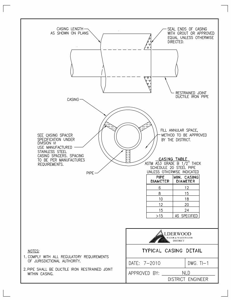
J. Obstruction removal records and testing results. 6-1.040 Construction Standards All materials, installation and workmanship shall be in accordance with the latest District standards and the latest edition of the State of Washington Standard Specifications for road, bridge and municipal construction. All applicable standards for water and/or sewer installations. Divisions 2, 3 and 7 shall also apply. 6-2.000 MATERIALS 6-2.010 General The Contractor shall furnish all material as noted herein and as indicated on the construction Drawings and as required to complete all work. All materials shall be manufactured with premium material and comply with all referenced standards. 6-2.020 Casing Pipe Casing pipe is typically used in microtunneling and pipe jacking applications. Calculations shall be provided for the proposed casing pipe material demonstrating sufficient capacity to accommodate highway loading during the life of the project and loading during installation. Casing pipe shall conform to all industry standards. Casing pipe that may be considered for District review includes steel or approved equal by the District. 6-2.030 Casing Spacers For microtunneling and pipe jacking applications, casing spacers shall be used to support the carrier pipe inside the casing pipe. Casing spacers shall be equally spaced within the casing and shall be sized to center the carrier pipe within the casing pipe. Casing spacers shall be as manufactured by Advanced Products and Systems Stainless Steel Band Casing Spacers,
Alderwood Water & Wastewater District Effective Date 5/6/2013 Development Standards Division 6 – Trenchless Installation Page 6 of 8
Model SSI, or Cascade Waterworks Manufacturing Company Stainless Steel Casing Spacer or approved equal. See Standard Detail TI-1. 6-2.040 Carrier Pipe For HDD applications the carrier pipe is typically installed without a casing pipe. For HDD installations the carrier pipe shall be high density polyethylene pipe (HDPE): A. Water & Sewer Force mains: HDPE pipe shall be extra high molecular weight HDPE pipe
conforming to all applicable AWWA and NSF standards and shall be equal to DriscoPlex 4000/4100 Series as manufactured by Performance Pipe, Chevron Phillips Chemical Company, SDR 9.
B. Sewer: High density polyethylene pipe shall be extra high molecular weight HDPE PE3408 for gravity sanitary sewer main applications with cell classification 345434C conforming to ASTM D3350 and shall be equal to DriscoPlex 4200/4300 Series as manufactured by Performance Pipe, Chevron Phillips Chemical Company, SDR 11.
For Microtunnel and Pipe Jacking Applications, the carrier pipe is installed inside the casing pipe. Carrier pipes that will be considered by the District include: A. Ductile Iron - Ductile iron (DI) pipe shall meet all requirements of Division 2 Water or Division
3 Sewer as applicable. In addition all DI pipe shall be restrained joint and Field-Lock gaskets are not acceptable as restrained joint.
B. Concrete polymer reinforced pipe.
C. HDPE as specified above. 6-2.050 Fittings Fittings and adapters shall match the pipe material being used. A. For HDPE pipe all fittings and adapters shall be molded and fabricated HDPE compatible
with the specified pipe, referenced standards and manufacturer requirements. All joints shall be butt-fused joints in accordance with referenced standards, and manufacturer requirements and using equipment specifically developed for joint fusions.
B. For DI pipe, all fittings and adapters shall meet all requirements of Division 2 Water or Division 3 Sewer as applicable. In addition, all DI pipe joints and adapters shall be restrained joint and Field-Lock gaskets are not acceptable as restrained joint.
6-2.060 Drilling Fluid Drilling fluid, if used, shall be a slurry mix specifically used for horizontal directional drilling or Microtunneling and shall be biodegradable and non-toxic.
Alderwood Water & Wastewater District Effective Date 5/6/2013 Development Standards Division 6 – Trenchless Installation Page 7 of 8
6-3.000 INSTALLATION 6-3.010 General When approved by the District trenchless methods may be considered an option for the Contractor. When approved by the District, use of HDD shall generally comply with the Horizontal Directional Drilling Manual as published by the North American Society for Trenchless Technology (NASTT) and standard industry requirements. When approved by the District, the use of microtunneling, auger bore, pipe ramming or pipe jacking shall generally comply with the Standard Construction Guidelines for Microtunneling as published by the American Society of Civil Engineers (ASCE) and standard industry requirements. 6-3.020 Trenching and Installation Pipe shall be installed to the lines and grades as shown on the plans and profiles. Because of the minimum pipe slopes and easement width, installation of the pipe shall be closely monitored to maintain the proper alignment. Easements allowed for construction shall be as shown on the plans. All debris caused by construction shall be removed from the premises and legally disposed of. Contractor is liable for damages caused to construction areas from heavy equipment and trucks. Contractor is responsible for restoring area when construction is complete. The equipment used during the drilling operation shall be determined by the Contractor. The approval of the equipment by the District in no way relieves the Contractor of the responsibility of damages of any nature that might occur as a result of the equipment used or of meeting the requirements of the contract documents, plans or specifications of this project. The Contractor's drilling equipment shall be equipped with an electrical strike by sensing both current and voltage. The strike system shall be equipped with warning strobes on both the drill frame and the power unit. Contractor shall supply grounding mats for the operator. Water required for the drilling operation may be obtained from the District if available. If available and the Contractor elects to use, Contractor shall apply to the District for a water use permit and shall furnish backflow prevention equipment according to District Standards. Water use shall follow the latest guidelines in accordance with District policy. Water for drilling operations shall not be used directly from a fire hydrant. The Contractor shall provide a tanker truck for use as a water reservoir for the drilling operation. Contractor shall provide portable fluid (mud) tanks at both entry and exit points to contain all drilling fluids resulting from the drilling operation and is responsible for proper disposal of all drilling fluids and waste tailings offsite unless a suitable location is approved by the District. For HDD installations, the pullback method shall be used to install the water/sewer lines. Once the pullback has begun, it shall be continuous until full completion. Contractor shall make preparations .for extended hours of operation during pullback of piping.
Alderwood Water & Wastewater District Effective Date 5/6/2013 Development Standards Division 6 – Trenchless Installation Page 8 of 8
Contractor shall maintain a minimum horizontal separation of ten (10) feet between all sewer and water lines except when placed in the same casing. Acceptable horizontal variances are plus or minus one (1) foot from the plan alignment. Acceptable vertical variances are plus or minus one-half foot from the elevation centerline or tighter, as shown in the Construction Drawings. For gravity sewer lines, pipe shall slope down continuously in the direction of flow. No sags in the pipeline are allowed. Contractor shall continuously record all measuring and gauging equipment used at all times during operation and pullback of the piping and the District shall have access to these records. Drilling fluids shall be recycled during the drilling operation whenever possible. Contractor shall use every available means to install the pipeline in accordance with the Construction Drawings and Contract Documents. This includes sealing and re-drilling all or any part of the pilot hole if the completed or partially completed pilot is not in compliance with the plans. In the event the pipeline becomes lodged and cannot be pulled out of the drilled hole during installation, the Contractor shall seal the pipeline and existing hole and re-drill a pilot hole and pullback the pipeline again. Drilling operations shall minimize impact on the environment. Contractor shall restore jobsite to original condition upon completion of all work activities. The entire length of the trenchless installation shall have a recorded profile upon completion. Information shall be continually recorded throughout the drilling operation by a surface computing system placed behind the bit. Contractor shall furnish this information to the District upon completion of the trenchless method operation. All HDPE pipe shall have butt-fused joints completed in accordance with the manufacturer's recommendations as to equipment and technique by workers who have a demonstrated ability and experience in the fusion process. HDPE pipe shall be butt-fused into the maximum available lengths prior to pulling the pipe into the directional drill hole. Following the joint fusion process of the HDPE, all interior butt welds shall be reamed to provide the full unobstructed inside diameter of the HDPE pipe for sewer installations. Following installation of the HDPE pipe by the directional boring technique, the pipe shall be allowed to return to its equilibrium length and temperature. No connections, pipe cutting or other work will be allowed on the HDPE pipe for 48 hours following installation. 6-3.030 Testing and Acceptance Trenchless methods shall be subject to all conditions and requirements of the applicable portions of Division 2-Water and/or Division 3-Sewer.

Alderwood Water & Wastewater District Effective Date 5/6/2013 Development Standards Division 7 – Aggregates. Trenching, Backfill, & Restoration Page 1 of 7
DIVISION 7
Standards
for
Aggregates, Trenching, Backfill,
& Restoration
Alderwood Water & Wastewater District Effective Date 5/6/2013 Development Standards Division 7 – Aggregates. Trenching, Backfill, & Restoration Page 2 of 7
Division 7
Standards for Aggregates, Trenching, Backfill, & Restoration
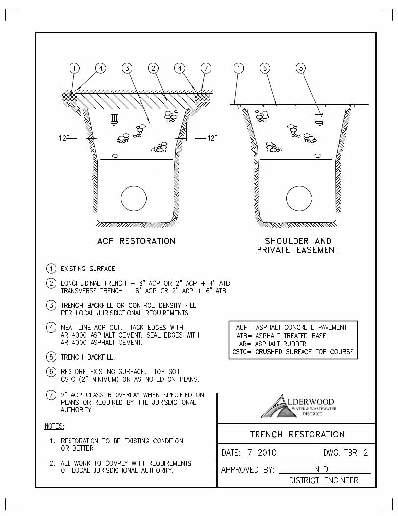
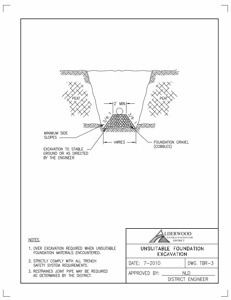
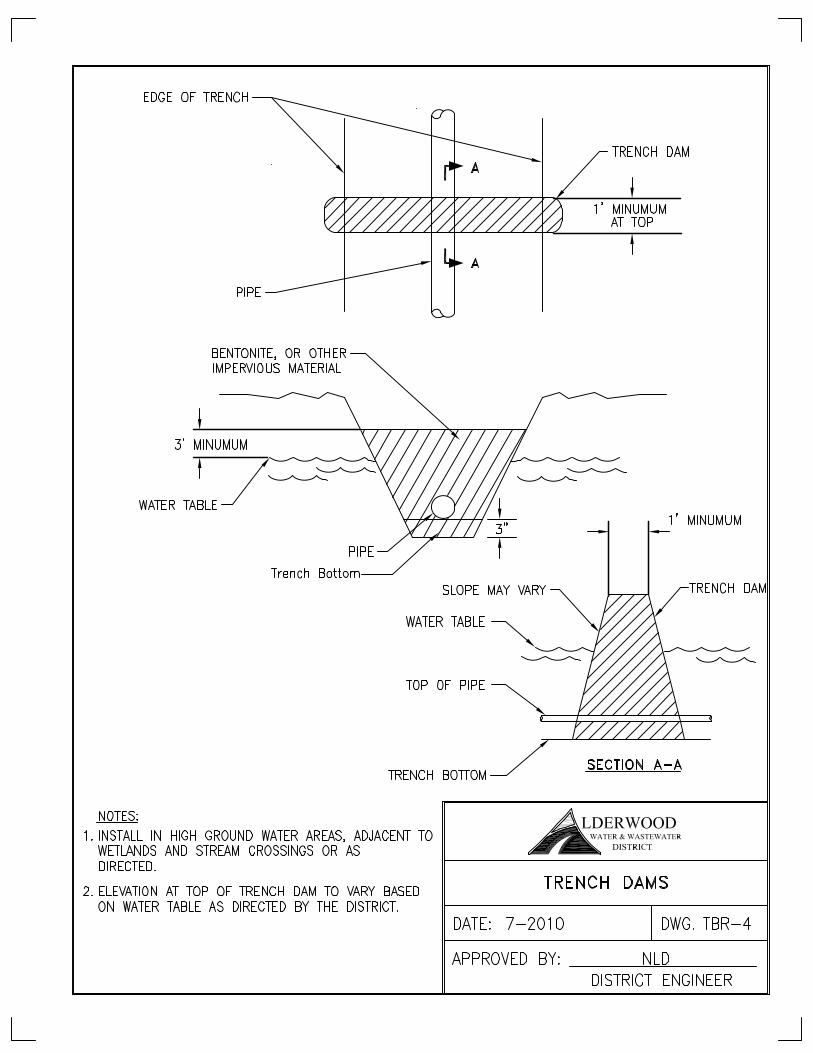
Table of Contents 7-1.000 GENERAL ................................................................................................................ 3 7-2.000 AGGREGATES ........................................................................................................ 3 7-2.010 Control Density Fill (CDF) ......................................................................................... 3 7-3.000 TRENCHING AND BACKFILL ................................................................................. 4 7-3.010 General .................................................................................................................... 4 7-3.020 Evaluation of Native Soil ........................................................................................... 5 7-3.030 Installation ................................................................................................................ 5 7-3.040 Frequency of Testing ................................................................................................ 6 7-3.060 Restoration ............................................................................................................... 6 7-3.070 Soil Amendments ..................................................................................................... 7 7-4.000 PERMANENT PAVEMENT REPAIR ........................................................................ 7 DETAILS Trench Section Pipe Bedding and Trench Backfill..…….…….……….………...…...…....…...…..TBR-1 Trench Surface Restoration………………………………………..………………………………….….TBR-2 Unsuitable Foundation Excavation………………...……….…………………….…….………....…....TBR-3 Trench Dams……………….………………..……………….…….……….….…..……….………...….…TBR-4 Concrete Anchor for Pipe in Steep Slopes……………………….…………..……………….…....…TBR-5
Alderwood Water & Wastewater District Effective Date 5/6/2013 Development Standards Division 7 – Aggregates. Trenching, Backfill, & Restoration Page 3 of 7
7-1.000 GENERAL The Contractor shall complete the installation of all furnished materials in accordance with the Construction Drawings and Standard Details, Specifications and in accordance with all State, District and other local regulatory authority requirements. The more stringent Standard or requirement shall apply unless agreed to by the District. 7-2.000 AGGREGATES A. Foundation Gravel: Comply with Section 9-03.17 of WSDOT Standard Specifications for
Class “A”. B. Bedding Material for Rigid Pipe (DI):
a. Sewer: Bedding shall be classified as pea gravel as shown in “Pea Gravel” this section.
b. Water: Bedding shall comply with Section 9-03.12(3) of WSDOT Standard Specifications.
C. Bedding Material for Flexible Pipe (PVC, HDPE): For all sewer lines, pipe bedding shall be
classified as pea gravel as shown below. For water lines, pipe bedding shall be classified as pea gravel as shown below, or Section 9-03.13 of WSDOT Standard Specifications as required by the District.
D. Bedding Material for Copper Tubing: Shall be classified as clean, rock free sand. E. Bank Run Gravel for Trench Backfill: Bank run gravel for trench backfill material shall
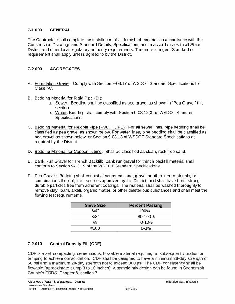
conform to Section 9-03.19 of the WSDOT Standard Specifications. F. Pea Gravel: Bedding shall consist of screened sand, gravel or other inert materials, or
combinations thereof, from sources approved by the District, and shall have hard, strong, durable particles free from adherent coatings. The material shall be washed thoroughly to remove clay, loam, alkali, organic matter, or other deleterious substances and shall meet the flowing test requirements.
Sieve Size Percent Passing
3/4” 100%
3/8” 80-100%
#8 0-10%
#200 0-3%
7-2.010 Control Density Fill (CDF) CDF is a self compacting, cementitious, flowable material requiring no subsequent vibration or tamping to achieve consolidation. CDF shall be designed to have a minimum 28-day strength of 50 psi and a maximum 28-day strength not to exceed 300 psi. The CDF consistency shall be flowable (approximate slump 3 to 10 inches). A sample mix design can be found in Snohomish County’s EDDS, Chapter 8, section 7.
Alderwood Water & Wastewater District Effective Date 5/6/2013 Development Standards Division 7 – Aggregates. Trenching, Backfill, & Restoration Page 4 of 7
7-3.000 TRENCHING AND BACKFILL 7-3.010 General The following trenching and backfill specifications and requirements apply to all water and sewer utility installations within the District. These standards represent the minimum requirements. Jurisdictional or other requirements shall apply in all cases when those standards and requirements exceed these minimums. The location of the pipe shall be shown on the Construction Drawings and field adjusted as approved by the District. During trenching, installation of pipelines and appurtenances and the placing of backfill, the trenches shall be kept free of water. The Contractor shall furnish all equipment necessary to dewater the trench and shall dispose of the water in such a manner as not to cause a nuisance or menace to the public and in accordance with State and local jurisdictional requirements. All trench excavations shall have adequate safety systems for the trench excavation that meet the requirements of the Washington Industrial Safety and Health Act, Chapter 49.17 RCW. The Contractor shall be fully responsible for providing the necessary back sloping, shoring, cribbing, trench boxes, etc., as required to meet the specific safety requirements for the trench. The Contractor’s attention is called to the depth of the structures and pipe which may require special shoring and bracing. The Contractor shall furnish all shoring and bracing or sheeting required to perform and protect the trench and to safeguard the workers. The Contractor shall follow all Federal and State regulations for trenching and backfill. No timber bracing, lagging, sheathing or other lumber shall be left in any excavation. The volume excavated that will be displaced by the pipe, bedding material and backfill shall be loaded, hauled and disposed of in a manner selected by the Contractor and approved by Snohomish County or other agency having jurisdiction. The Contractor shall be responsible for obtaining any City, County, State or other agency permits for such disposal sites and shall pay all fees and charges associated therewith. Trench backfill material above the piping and bedding material shall be bank run gravel or select native material. Material shall require approval by the Contractor’s geotechnical consultant and the District prior to using. Excavation and backfill compaction shall be performed in accordance with standard construction practices to achieve the required compaction. Compaction and acceptance shall be subject to approval of the jurisdictional authority and the District. Backfill compaction shall occur in sufficiently thin lifts to achieve the density requirements specified. Such compaction shall be performed to within 6-inches of existing road grade. In areas of existing pavement, after placing a tack coat on the existing asphalt edges, the final patch shall be constructed in accordance with Standard Detail TBR-2 using a minimum of 6-inches of hot mix asphalt (HMA) class ½ or ¾ inch, or 4-inches of HMA class 1 inch and 2-inches of HMA class ½ or ¾ inch placed in the trench up to finished grade or in accordance with jurisdictional requirements and whichever is more stringent shall apply.
Alderwood Water & Wastewater District Effective Date 5/6/2013 Development Standards Division 7 – Aggregates. Trenching, Backfill, & Restoration Page 5 of 7
Where the undisturbed conditions of natural soils are inadequate for support of the planned construction, excavation shall be extended 8-inches minimum below the structure or pipeline grades to permit the placing and compacting of foundation gravel. All natural soils inadequate for support of planned construction shall be removed to the depth of natural soils adequate for support. Trench cross-sectional width shall conform to the trench details shown on the Construction Drawings and Standard Details. Trench dams shall be installed across the entire trench section and to the full depth of all granular backfill materials in all areas where excessive amounts of water can enter and follow the trench line including steep slopes, stream and wetlands crossings and as determined by the District and other local governmental authorities. See Standard Detail TBR-4 in Division 7. Testing frequency shall comply with section 7-3.040. Areas that fail to pass testing shall require retesting at locations determined by the District. 7-3.020 Evaluation of Native Soil The Contractor’s geotechnical consultant shall complete a thorough evaluation of native soil. Soil evaluations, sieve analysis and proctor tests shall be completed prior to and during construction for varying soil conditions as determined by the geotechnical consultant. The geotechnical consultant shall verify that material can achieve compaction under varying weather conditions. At any time native materials are determined to be unsuitable to obtain compaction or do not meet specified gradation, imported materials shall be provided in accordance with the specifications. Material source shall be provided and approved by the District. All acceptance tests shall be conducted from in-place samples. Compaction testing shall be accomplished using a nuclear densometer. Compaction testing results sent to the District shall include a copy of the material proctor results and the precise location of area tested by referencing the horizontal and vertical location on Construction Drawings. 7-3.030 Installation Prior to excavation and installation, equipment capable of achieving adequate compaction shall be on site. Backfill and compaction shall be completed in conjunction with the pipeline installation. Prior to the District accepting the water and/or sewer mains for use and operation, compaction testing showing adequate compaction shall be verified by the District. The District highly recommends that compaction testing be completed in conjunction with the installation of backfill and compaction. Copies of compaction testing, reports,soils analysis and proctor tests shall be provided to the District to verify compaction requirements prior to pressure testing. A. Utility Trenches in the Existing Right-of-Way: Trench backfill material and compaction shall
conform to the jurisdictional requirements of the Entity/Owner of the existing right-of-way or follow the District Standards, and whichever is more stringent shall apply.
B. Utility Trenches in Proposed or Existing Traffic Areas, including Driveways Easements: All
trench backfill shall be mechanically compacted to 95 percent of maximum density in accordance with ASTM 1557 (modified proctor).
Alderwood Water & Wastewater District Effective Date 5/6/2013 Development Standards Division 7 – Aggregates. Trenching, Backfill, & Restoration Page 6 of 7
C. Utility Trenches in Non-Paved, Non-Structured Areas and Designated Wetlands: All trench backfill shall be mechanically compacted to 90 percent of maximum density in accordance with ASTM 1557 (modified proctor). Compaction testing as specified in Section 2-03.3(14) D of the WSDOT/APWA Specifications and as specified by the local jurisdiction, shall be required.
D. Utility Trenches in Areas Near Structures: Structures located within a 1:1 slope from bottom
of the trench excavation to the projection of the slope to finished grade shall be deemed as lying in the “Zone of Influence” of the excavation and the trench in the easement area within the zone of influence shall be backfilled with flowable CDF from the top of bedding to a depth that the structure is outside the zone of influence.
7-3.040 Frequency of Testing A. Horizontally: Minimum of two locations every 200 feet of trench, or a minimum of two
locations per day or a minimum of 2 locations per pipe run between manholes and/or valves whichever is more frequent shall apply. Additional tests may be required when variations occur due to the Contractors operations, weather conditions, site conditions, etc.
B. Vertically: For trenches 12-feet and under; complete a minimum of one test at approximately
one half of the trench depth and an additional test at or near the surface. For trenches 12-feet to 16-feet deep; complete one test at approximately 4-feet above the pipe, one test at or near the surface and one test approximately halfway in between. For trenches greater than 16-feet deep; complete tests at approximately four foot intervals above the pipe to the surface (four tests required) or as directed by the District. Structured areas, such as an easement near a building, shall require additional testing in the zone of influence from the licensed geotechnical consultant such that the compaction shall not adversely affect the nearby or surrounding structures. If compaction within any area of the project is questionable as determined by the District and prior to paving, additional excavation and testing as directed by the District shall be completed. Compaction testing costs are the responsibility of the Contractor. Copies of all testing reports shall be provided to the District for verification and project records and jurisdictional approvals.
7-3.060 Restoration The Contractor shall prepare and restore all test sites with his own equipment, labor and materials. All costs incidental to the preparation and restoration of all test sites shall be at the Contractor’s expense. The Contractor shall remedy, at his expense, any defects that appear in the backfill prior to final acceptance of the work. Upon completion of work each day, all open trenches shall be completely backfilled and leveled. In paved areas, temporarily patch with 3 inches of cold mix asphalt concrete (or as specified by
Alderwood Water & Wastewater District Effective Date 5/6/2013 Development Standards Division 7 – Aggregates. Trenching, Backfill, & Restoration Page 7 of 7
the regulatory authority) except in areas designated for Control Density Fill (CDF). Where CDF is used it shall be placed in accordance with the jurisdictional authority. Trenches not backfilled at the end of the day may be covered with steel plates or other materials providing safety and protection for the public and as approved by the jurisdictional authority. Prior to placing CDF over ductile iron pipe or fittings, the pipe bedding material around the pipe shall be placed and compacted. 7-3.070 Soil Amendments Amendments to soil such as kiln dust will be considered by the District if:
a. The recommendation is made by the Contractor’s geotechnical consultant. b. The geotechnical consultant verifies the proposal complies with the jurisdictional
authority requirements if applicable. c. The Contractor takes full responsibility for any impacts placed on surrounding areas. d. The amendment shall be used the entire trench depth. (Bridging lower portions of trench
line shall not be allowed). Use of soil amendments shall be approved by the District prior to placement. The District reserves the right to deny use of soil amendments at the District’s discretion. Soil amendments used and without prior approval from the District shall be removed at the Contractor’s cost. If amendments are approved by the District, the geotechnical consultant shall witness and document the mixture of the additive. Compaction tests that meet these standards shall be required at the frequency and depths specified. 7-4.000 PERMANENT PAVEMENT REPAIR Pavement repair shall follow the governing jurisdictional authority when in the right-of-way. The District’s standards are to be followed in the easements. Where Standards differ, the most stringent shall apply as determined by the District. A. Asphalt Concrete Pavement Repair. Asphalt concrete pavement repair shall be asphaltic
concrete pavement HMA class ½ or ¾ and shall conform and be placed in accordance with the requirements of Section 4-06 and 5-04 WSDOT. Before pavement is placed, all edges and joints of asphaltic concrete pavement shall be tacked with:
1. Asphalt Sealer SS 1 or equal.
2. After pavement is in place, all joints shall be sealed with hot asphalt cement, AR 4000 Grade and sand placed on sealant to prevent tracking by vehicles.