appendix fa - official website | official website
TRANSCRIPT

September 7, 2017 (Revised November 1, 2017)
Project No. 10113.002
Environmental Advisors 2400 East Katella Avenue, Suite 800 Anaheim, California 92806
Attention: Mr. Greg McCafferty
Subject: Response to Geotechnical Engineering Review Sheet Ball Road Basin General Plan Amendment Southeast Corner of Ball Road and South Phoenix Drive Anaheim, California
References: Leighton Consulting, Inc., 2013, Preliminary Geotechnical Assessment, Ball Road Basin General Plan Amendment and Zone Change Project, Anaheim, California, dated March 18, 2013 (Revised June 13, 2013), Project No. 10113.002.
Leighton Consulting, Inc., 2017, Addendum to Preliminary Geotechnical Assessment, Ball Road Basin Redevelopment, Anaheim, California, dated March 17, 2017, Project No. 10113.002.
INTRODUCTION
Leighton Consulting, Inc. has prepared this report in response to the geotechnical engineering review sheet dated April 24, 2017, regarding the referenced reports for Ball Road Basin General Plan Amendment and Zone Change Project. A copy of subject review sheet is attached. The comments are presented below in italics followed by our responses. Responses to Comments 1 and 2 were previously provided on June 5, 2017, and are repeated below for completeness. This report has been revised to incorporate our responses to the additional review comments emailed to us on October 13, 19, and 23, 2017.

10113.002
2
EXISTING INFORMATION AND ASSUMPTIONS
Comments 3 through 6 request for quantitative evaluation of secondary effects of seismic shaking (lateral spreading and seismically induced landsliding), compressible soils and settlement monitoring, and slope stability. Such evaluation is not typically performed for a feasibility level geotechnical study as it requires design level information such as detailed subsurface conditions, planned finish grades, and proposed development. However, subsurface information is available from the field exploration that Leighton Consulting performed for the City of Anaheim in 2016 of which we obtained permission from the City of Anaheim on July 20, 2017 to use the data for preparation of this response report. The field exploration consisted of two hollow-stem auger borings (LB-1 and LB-2) to a depth of 52 feet and seven CPTs (CPT-1 through CPT-7) to depths of 45 to 50 feet. Location of the borings and CPTs is presented on Figure 2 of Appendix A. For the planned finish grades, we assume that the basin will be filled to an elevation similar to the surrounding grades. The toe of the new fill is assumed to be set back 10 feet from the toe of the Center Levee as shown on the cross section in Appendix A. As far as the proposed development, we assume the site will be developed for non-essential facility such as commercial development or a parking structure.
RESPONSE TO REVIEW COMMENTS
Comment 1: Section 2.2 Local Geology- Since the site has significant grade differences, references to depths in this section are difficult to interpret. Please include reference to elevations in the discussion. Response to Comment 1: Section 1.2 indicates that elevations on the Project site range from approximately 155 feet at the invert to approximately 180 feet at the top-of-grade. The depths in Section 2.2 are in reference to the invert elevation. Comment 2: Section 2.3 Groundwater- The log for OCWD BRB-1 indicated that groundwater was encountered near an elevation of 154’. This elevation is significantly higher than implied by the elevations stated for nearby wells. Please discuss in greater detail the estimated depths/elevations to groundwater at the site, the estimated magnitude of variations in groundwater over the life of the project, and estimated shallowest groundwater condition likely to exist during the project life span.

10113.002
3
Response to Comment 2: As indicated in this section, groundwater in the area appears to be influenced by the water level in the recharge basins and Santa Ana River. Fluctuations of the groundwater level, localized zones of perched water, and an increase in soil moisture should be anticipated depending on the water level in the basins and river, and during and following the rainy seasons or periods of locally intense rainfall or storm water runoff, or future stormwater infiltration.
Comment 3: Section 3.1.3 Secondary Effects of Seismic Shaking- Lateral Spreading- The site appears to present a significant potential for lateral spreading due to a loose sandy layer near an elevation of 155 feet. Should this layer be found to be liquefiable, lateral spreading could occur near the elevation of the adjacent river bottom making for a particularly unstable configuration. The consultant has not provided any analyses to evaluate the potential magnitude of lateral spreading. If the magnitude of lateral spreading is large, the mitigation could require large-scale costs to implement. The consultant should provide a quantitative analysis of the potential for lateral spreading and address in more detail the potential method(s) of mitigation, if required.
Response to Comment 3: Slope stability analysis was conducted on Cross-Section B-B’ (see Appendix A) to evaluate the potential for lateral spreading. The shear strength parameters used in the analysis were obtained from direct shear test results, correlation with SPT blowcounts and relative density, and CPT data. The sand underlying the basin down to Elevation 134 feet is potentially liquefiable and is modelled with a post liquefaction residual strength of 500 psf. The calculated factor of safety for a pseudostatic condition with liquefied soils was less than 1.0 (see Appendix A). Ground improvement may be performed to reduce the potential for lateral spreading. For planning purposes, the ground improvement area is estimated to be approximately 50 feet wide, extending to a depth of 25 feet. Slope stability analysis with this preliminary ground improvement layout is also presented in Appendix A.
In response to the additional comments emailed to us on October 13, 19, and 23, 2017, we have performed slope stability analysis using the profile shown on the Conceptual Grading Exhibit dated May 10, 2013, prepared by Fuscoe Engineering. This grading exhibit assumes that the basin would be completely filled. In the analysis, the above-mentioned ground improvement layout was moved to the property line, which we understand is at the centerline of the Center Levee. The slope stability analysis, presented in Appendix A, shows that a setback zone of approximately 60 feet from the property line should be considered in preliminary development planning of the site based on the Conceptual Grading Exhibit.

10113.002
4
Comment 4: Section 3.1.3 Secondary Effects of Seismic Shaking- Seismically Induced Landslide- The potential methods of mitigation suggested are shear keys, flattening of slopes, or setbacks from the top of slopes. Considering the slope in question is offsite to the project, construction of shear keys or flattening of slopes would not seem to be viable options. Please clarify how these options can be considered. Further, if setbacks were required as a mitigation, please discuss the likely distances of such setbacks since large setbacks could have a significant impact on the project viability.
Response to Comment 4: The potential mitigation measures using shear keys and flattening of slopes are not intended for the Center Levee, which is owned and maintained by the U.S. Army Corps of Engineers (USACE). They are considered for the new fill slope within the project limits. Setback from top of the fill slope will not be necessary if ground improvement or shear keys are constructed.
Comment 5: Section 3.2.3 Compressible Soils- Due to the significant thickness of fill, the magnitude of settlement could be very significant. Clay layers undergoing consolidation could require a significant amount of time to reach a tolerable degree of settlement for proposed site development. Please discuss in more detail the likely time-frames involved in monitoring of settlement and delays to construction.
Response to Comment 5: Settlement of the new fill is expected to consist of two components: settlement of the alluvial deposits due to fill placement and settlement of the fill under its own weight. The magnitude of settlement will vary, depending on the location and the thickness of fill placed and the soil type used for fill and continuity of compressible stratigraphy below the site. Based on our preliminary data, we anticipate the maximum settlement of alluvium due to fill placement to be on the order of 8 inches. Settlement of the fill under its own weight is difficult to estimate without specific data of the fill material and engineering properties. Although some of the settlement is expected to occur during construction, we recommend monitoring of the new fill for settlement. For planning purposes, a waiting period on the order of 6 months should be considered between the completion of fill placement and construction of improvements.
Comment 6: Section 3.3 Slope Stability- Same comment as Item 4 above.
Response to Comment 6: Slope stability is addressed in Response to Comment 4 above.

10113.002
5
CLOSING
If you have any questions regarding this response, please contact the undersigned directly at the e-mail addresses and phone numbers listed below, or at 866-LEIGHTON.
Respectfully submitted,
LEIGHTON CONSULTING, INC.
Joe A. Roe, PG, CEG 2456 Principal Geologist [email protected], (949) 681-4263
Djan Chandra, PE, GE 2376 Senior Principal Engineer [email protected], (949) 681-4267
DJC/JR/lr
Attachments: Geotechnical Engineering Review Sheet dated April 24, 2017, by Albus-Keefe & Associates, Inc. Appendix A – Preliminary Slope Stability Analysis
Distribution: (1) Addressee (PDF via email)
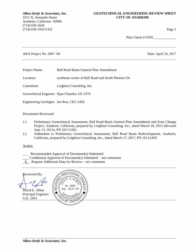
Albus-Keefe & Associates, Inc. GEOTECHNICAL ENGINEERING REVIEW SHEET 1011 N. Armando Street CITY OF ANAHEIM Anaheim, California 92806 (714) 630-1626 (714) 630-1916 FAX Page 1
Plan Check # OTH _____________
AKA Project No. 2607 .00 Date: April 24, 2017
Albus-Keefe & Associates, Inc.
Project Name: Ball Road Basin General Plan Amendment Location: southeast corner of Ball Road and South Phoenix Dr. Consultant: Leighton Consulting, Inc. Geotechnical Engineer: Djan Chandra, GE 2376 Engineering Geologist: Joe Roe, CEG 2456
Documents Reviewed:
1.) Preliminary Geotechnical Assessment, Ball Road Basin General Plan Amendment and Zone Change
Project, Anaheim, California, prepared by Leighton Consulting, Inc., dated March 18, 2013 (Revised June 13, 2013), PN 10113.002
2.) Addendum to Preliminary Geotechnical Assessment, Ball Road Basin Redevelopment, Anaheim, California, prepared by Leighton Consulting, Inc., dated March 17, 2017, PN 10113.002
Action: Recommended Approval of Document(s) Submitted Conditional Approval of Document(s) Submitted – see comments X_ Request Additional Data for Review – see comments Reviewed By: David E. Albus Principal Engineer G.E. 2455

Albus-Keefe & Associates, Inc. GEOTECHNICAL ENGINEERING REVIEW SHEET 1011 N. Armando Street CITY OF ANAHEIM Anaheim, California 92806 (714) 630-1626 (714) 630-1916 FAX Page 2
Plan Check # OTH _____________
AKA Project No. 2607 .00 Date: April 24, 2017
Albus-Keefe & Associates, Inc.
COMMENTS
The documents reviewed have been submitted to the City of Anaheim as geotechnical documents in support of an EIR for a proposed modification to the general zoning plan. The review of the documents was limited to establishing the feasibility of the proposed project. Additional geotechnical studies and detailed recommendations for project design and construction will be required during submittals of any future site development plans. 1. Section 2.2 Local Geology- Since the site has significant grade differences, references to
depths in this section are difficult to interpret. Please include reference to elevations in the discussion.
2. Section 2.3 Groundwater- The log for OCWD BRB-1 indicated that groundwater was encountered near an elevation of 154’. This elevation is significantly higher than implied by the elevations stated for nearby wells. Please discuss in greater detail the estimated depths/elevations to groundwater at the site, the estimated magnitude of variations in groundwater over the life of the project, and estimated shallowest groundwater condition likely to exist during the project life span.
3. Section 3.1.3 Secondary Effects of Seismic Shaking- Lateral Spreading- The site appears to present a significant potential for lateral spreading due to a loose sandy layer near an elevation of 155 feet. Should this layer be found to be liquefiable, lateral spreading could occur near the elevation of the adjacent river bottom making for a particularly unstable configuration. The consultant has not provided any analyses to evaluate the potential magnitude of lateral spreading. If the magnitude of lateral spreading is large, the mitigation could require large-scale costs to implement. The consultant should provide a quantitative analysis of the potential for lateral spreading and address in more detail the potential method(s) of mitigation, if required.
4. Section 3.1.3 Secondary Effects of Seismic Shaking- Seismically Induced Landslide- The potential methods of mitigation suggested are shear keys, flattening of slopes, or setbacks from the top of slopes. Considering the slope is question is offsite to the project, construction of shear keys or flattening of slopes would not seem to be viable options. Please clarify how these options can be considered. Further, if setbacks were required as a mitigation, please discuss the likely distances of such setbacks since large setbacks could have a significant impact on the project viability.
5. Section 3.2.3 Compressible Soils- Due to the significant thickness of fill, the magnitude of settlement could be very significant. Clay layers undergoing consolidation could require a significant amount of time to reach a tolerable degree of settlement for proposed site development. Please discuss in more detail the likely time-frames involved in monitoring of settlement and delays to construction.

Albus-Keefe & Associates, Inc. GEOTECHNICAL ENGINEERING REVIEW SHEET 1011 N. Armando Street CITY OF ANAHEIM Anaheim, California 92806 (714) 630-1626 (714) 630-1916 FAX Page 3
Plan Check # OTH _____________
AKA Project No. 2607 .00 Date: April 24, 2017
Albus-Keefe & Associates, Inc.
6. Section 3.3 Slope Stability- Same comment as Item 4 above.

APPENDIX A

Figure 2
Leighton
P:\DRAFTING\10113\004\CAD\2016-03-09\10113-004_F02_BLM_20160410.DWG (04-11-16 5:45:38PM) Plotted by: btran
Proj: 10113.004
BORING AND CPT LOCATION MAPBALL ROAD BASIN
CITY OF ANAHEIM, CALIFORNIA
Eng/Geol: DJC
Scale: 1"=150' Date: 04/2016
Reference:
SCALE FEET
0 150 300
APPROXIMATE LOCATION OF CONE PENETRATION TEST (CPT)
WITH TOTAL AND GROUNDWATER DEPTH
APPROXIMATE LOCATION OF HOLLOW-STEM AUGER BORING
WITH TOTAL AND GROUNDWATER DEPTH
BURRIS BASIN OVERFLOW DRAIN
OCFCD CHANTILLY STORM DRAIN (CSD)
GEOTECHNICAL CROSS SECTIONS
B B'
LEGEND

W
Center Levee
Santa Ana River
Ball Road Basin Invert
Material Name Color Unit Weight(lbs/ 3) Strength Type Cohesion
(psf)Phi(deg) Water Surface
Ar ficial Fill 120 Mohr‐Coulomb 50 32 Water Surface
SP/SM/SP‐SM (Liq) 120 Mohr‐Coulomb 500 0 Water Surface
CL 120 Mohr‐Coulomb 1000 0 Water Surface
SP/SM 120 Mohr‐Coulomb 0 34 Water Surface
Artificial Fill
SP/SM/SP-SM (Liq)
CL
SP/SM
Approximate Toe of Center Levee
10 ftNew Artificial Fill
Method: spencerFactor of Safety: 0.76Axis Location: -59.754, 404.871Left Slip Surface Endpoint: -194.690, 180.007Right Slip Surface Endpoint: 39.176, 162.004
0.15
300
250
200
150
100
-150 -100 -50 0 50 100 150 200
P:\INFOCUS PROJECTS\10000-10500\10113 EA-Ball Rd Basin\004 Ball Rd Basin Geo Exploration\Analyses\Slope Stability\04-11-16 final\Sec B Fill Post Liquefaction.slim
Fill OptionSection B - B' - Post Liquefaction
Project No.:
10113.004
Scale1:480
Unitsfeet
Analyzed BySreekar Pulijala
ConditionPost-Liquefaction
Date4/8/2016, 9:44:59 AM
Project
Ball Road Basin Park SLIDEINTERPRET 7.009

W W
Center Levee
Santa Ana River
Ball Road Basin Invert
Material Name Color Unit Weight(lbs/ 3) Strength Type Cohesion
(psf)Phi(deg) Water Surface
Ar ficial Fill 120 Mohr‐Coulomb 50 32 Water Surface
SP/SM/SP‐SM (Liq) 120 Mohr‐Coulomb 500 0 Water Surface
CL 120 Mohr‐Coulomb 1000 0 Water Surface
SP/SM 120 Mohr‐Coulomb 0 34 Water Surface
Ground Improvement 120 Mohr‐Coulomb 50 34 Water Surface
Artificial Fill
SP/SM/SP-SM (Liq)
CL
SP/SM/SP-SM (Non-Liq)
SP/SM
Approximate Toe of Center Levee
10 ftNew Artificial Fill
Method: spencerFactor of Safety: 1.24Axis Location: -52.487, 391.726Left Slip Surface Endpoint: -180.692, 180.007Right Slip Surface Endpoint: 39.966, 162.131
0.15
300
250
200
150
100
-150 -100 -50 0 50 100 150 200
P:\INFOCUS PROJECTS\10000-10500\10113 EA-Ball Rd Basin\004 Ball Rd Basin Geo Exploration\Analyses\Slope Stability\04-11-16 final\Sec B Fill Post Liquefaction GIMP.slim
Fill OptionSection B - B' - Post Liquefaction with Ground Improvement
Project No.:
10113.004
Scale1:480
Unitsfeet
Analyzed BySreekar Pulijala
ConditionPost-Liquefaction
Date4/8/2016, 9:44:59 AM
Project
Ball Road Basin Park SLIDEINTERPRET 7.009

W
Property Line
Santa Ana River
Ball Road Basin Invert
Material Name Color Unit Weight(lbs/ 3) Strength Type Cohesion
(psf)Phi(deg) Water Surface
Ar ficial Fill 120 Mohr‐Coulomb 50 32 Water Surface
SP/SM/SP‐SM (Liq) 120 Mohr‐Coulomb 500 0 Water Surface
CL 120 Mohr‐Coulomb 1000 0 Water Surface
SP/SM 120 Mohr‐Coulomb 0 34 Water Surface
Ground Improvement 120 Mohr‐Coulomb 50 38 Water Surface
New Fill
SP/SM/SP-SM (Liq)
CL
Method: spencerFactor of Safety: 1.02Axis Location: 165.603, 344.693Left Slip Surface Endpoint: 55.321, 179.193Right Slip Surface Endpoint: 231.834, 157.168Left Slope Intercept: 55.321 179.193Right Slope Intercept: 231.834 160.000
43 ft
Ground Improvement
Existing Fill
Center Levee
0.15
300
250
200
150
-50 0 50 100 150 200 250 300
P:\INFOCUS PROJECTS\10000-10500\10113 Ball Rd Basin\004 Ball Rd Basin Geo Exploration\Analyses\Slope Stability\10-20-17\Sec B Fill Post Liquefaction GIMP_setback.slim
Fill Option
Section B - B' - Post Liquefaction with Ground Improvement
Sec B Fill Post LiquefactionGIMP_setback.slim
Project No.:
10113.004
Scale1:480
Unitsfeet
Analyzed BySP/CD
ConditionPost-Liquefaction
DateOctober 2017
Project
Ball Road Basin Park SLIDEINTERPRET 7.009

W
Property Line
Santa Ana River
Ball Road Basin Invert
Material Name Color Unit Weight(lbs/ 3) Strength Type Cohesion
(psf)Phi(deg) Water Surface
Ar ficial Fill 120 Mohr‐Coulomb 50 32 Water Surface
SP/SM/SP‐SM (Liq) 120 Mohr‐Coulomb 500 0 Water Surface
CL 120 Mohr‐Coulomb 1000 0 Water Surface
SP/SM 120 Mohr‐Coulomb 0 34 Water Surface
Ground Improvement 120 Mohr‐Coulomb 50 38 Water Surface
New Fill
SP/SM/SP-SM (Liq)
CL
Method: bishop simplifiedFactor of Safety: 1.00Center: 163.226, 313.889Radius: 180.878Left Slip Surface Endpoint: 42.382, 179.302Right Slip Surface Endpoint: 253.440, 157.115Left Slope Intercept: 42.382 179.302Right Slope Intercept: 253.440 160.000
59 ft
Ground Improvement
Existing Fill
Center Levee
0.15300
250
200
150
-50 0 50 100 150 200 250 300
P:\INFOCUS PROJECTS\10000-10500\10113 Ball Rd Basin\004 Ball Rd Basin Geo Exploration\Analyses\Slope Stability\10-20-17\Sec B Fill Post Liquefaction GIMP_setback-circle.slim
Fill Option
Section B - B' - Post Liquefaction with Ground Improvement
Sec B Fill Post LiquefactionGIMP_setback-circle.slim
Project No.:
10113.004
Scale1:480
Unitsfeet
Analyzed BySP/CD
ConditionPost-Liquefaction
DateOctober 2017
Project
Ball Road Basin Park SLIDEINTERPRET 7.009