appendix a. design guidelines - san mateo, california
TRANSCRIPT

City of San Mateo | Bicycle Master Plan
Alta Planning + Design | A-1
Appendix A. Design Guidelines This appendix presents an overview of bicycle facility designs, based on appropriate California Manual of
Uniform Traffic Control Devices (California MUTCD) and Highway Design Manuals, and supplemented by
AASHTO best practices and San Mateo-specific design guidelines. The purpose is to provide readers and
project designers with an understanding of the facility types that are proposed in the Plan, and with specific
treatments that are recommended or required.

Appendix A | Design Guidelines
A-2 | Alta Planning + Design
Appendix A Table of Contents A.1. Bicycle Design Standards ..................................................................................................................................... A-4
A.2. Bikeway Classification .......................................................................................................................................... A-6
A.2.1. Bikeway Classification Overview ............................................................................................................... A-6
A.3. Shared Use Paths ..................................................................................................................................................... A-8
A.3.1. General Design Practices: ............................................................................................................................. A-8
A.3.2. Pathway Design ............................................................................................................................................... A-9
A.3.3. Bollards ............................................................................................................................................................. A-11
A.3.4. Recommended Path Signage ...................................................................................................................... A-12
A.4. Pathway Crossing .................................................................................................................................................. A-13
A.4.1. Treatments...................................................................................................................................................... A-13
A.4.2. Path Crossing at Intersection .................................................................................................................... A-14
A.4.3. Uncontrolled Mid-Block Crossing ........................................................................................................... A-17
A.4.4. Crossing Beacons ......................................................................................................................................... A-20
A.4.5. Signalized Mid-Block Crossing ................................................................................................................. A-21
A.5. On-Street Bicycle Facility Design .................................................................................................................... A-22
A.5.1. Bike Lanes ...................................................................................................................................................... A-22
A.5.2. General Design Guidance: ......................................................................................................................... A-22
A.5.3. Bike Lane with No On-Street Parking .................................................................................................... A-23
A.5.4. Bike Lane With On-Street Parallel Parking .......................................................................................... A-24
A.6. Bike Routes............................................................................................................................................................. A-25
A.6.1. General Design Guidance: ......................................................................................................................... A-25
A.6.2. Bike Route ..................................................................................................................................................... A-26
A.6.3. Class III Bike Route with Shared Lane Markings (SLM) ................................................................... A-27
A.6.4. Additional Bike Route Signage ................................................................................................................. A-28
A.6.5. Bicycle Boulevards ....................................................................................................................................... A-29
A.6.6. Buffered Bike Lanes ...................................................................................................................................... A-31
A.6.7. Colored Bike Lanes ...................................................................................................................................... A-32
A.6.8. Manholes & Drainage Grates .................................................................................................................... A-33
A.6.9. Bicycle Access During Construction Activities .................................................................................... A-34

City of San Mateo | Bicycle Master Plan
Alta Planning + Design | A-3
A.7. Intersection and Interchange Design for Bicyclists .................................................................................... A-36
A.7.1. Bicycle Detection at Signalized Intersections ........................................................................................A-36
A.7.2. Loop Detector Pavement Markings and Signage .................................................................................. A-38
A.7.3. Bike Lane at Intersection with Right Turn Only Lane ....................................................................... A-39
A.7.4. Bicycle Boxes .................................................................................................................................................. A-41
A.7.5. Interchange Design ...................................................................................................................................... A-42
A.7.6. Accommodating Bicyclists at On and Off-Ramps ............................................................................... A-43
A.7.7. Bicycle and Pedestrian Overcrossing Design ........................................................................................ A-45
A.7.8. Bicycle and Pedestrian Undercrossing Design ..................................................................................... A-47
A.8. Design of Interpretive and Wayfinding Signage .......................................................................................... A-49
A.8.1. Wayfinding Signage - General .................................................................................................................. A-49
A.9. Bicycle Parking ....................................................................................................................................................... A-51
A.9.1. Bicycle Rack Design ..................................................................................................................................... A-51
A.9.2. Bicycle Locker Design .................................................................................................................................. A-53
A.10. Maintenance Standards ...................................................................................................................................... A-54
A.10.1. Shared Use Path Maintenance Standards .............................................................................................. A-55
A.10.2. On-Street Facility Maintenance Standards ............................................................................................ A-57

Appendix A | Design Guidelines
A-4 | Alta Planning + Design
A.1. Bicycle Design Standards The City of San Mateo Bicycle Design Guidelines present standards and recommendations that specifically
provide for consistency in the City of San Mateo, or where details are needed beyond what is provided by
state and federal design standards. All projects must also meet state and federal design standards. Therefore,
in addition to these City of San Mateo Design Guidelines, engineers, planners and designers should also refer
to the following documents and their subsequent updates when planning and designing bicycle and
pedestrian facilities.
Signage in San Mateo is governed by the California MUTCD. As of January 21, 2010, the California
Department of Transportation (Caltrans) has revised the California MUTCD 2010 to include FHWA’s 2003
MUTCD Revision 2 dated December 21, 2007. FHWA has released the new 2009 MUTCD but it is not
effective in California until Caltrans and the California Traffic Control Devices Committee (CTCDC) review
it and incorporate the changes into California MUTCD through formal efforts. California has until January 15,
2012 to accomplish this task and a Draft 2011 MUTCD is currently under review. In the event that a specific
treatment is not in the California MUTCD, it may be necessary to go through experimental testing
procedures. Experimental testing is overseen by the California Traffic Control Devices Committee.
The following manuals, guides, policies, directives, and plans informed these design guidelines:
California Manual on Uniform Traffic Control Devices, 2010 Update.
http://www.dot.ca.gov/hq/traffops/signtech/mutcdsupp/ca_mutcd2010.htm
Manual on Uniform Traffic Control Devices (MUTCD), Federal Highway Administration.
http://mutcd.fhwa.dot.gov/
Caltrans Complete Intersections: A Guide to Reconstructing Intersections and Interchanges for
Bicyclists and Pedestrians (2010).
Caltrans Policies and Directives. http://www.dot.ca.gov/hq/traffops/signtech/signdel/policy.htm
including:
o Traffic Operations Policy Directive 09-06 “Provide Bicycle and Motorcycle Detection on
all new and modified approaches to traffic-actuated signals in the state of California.”
o Caltrans Deputy Directive DD-64 “ Complete Streets – Integrating the Transportation
System.”
o Caltrans Highway Design Manual. http://www.dot.ca.gov/hq/oppd/hdm/hdmtoc.htm
o Caltrans Design Information Bulletins. http://www.dot.ca.gov/hq/oppd/dib/dibprg.htm
including:
DIB 80-01 Roundabouts
DIB 82-03 Design Information Bulletin 82-03 “Pedestrian Accessibility
Guidelines for Highway Projects”
o Caltrans Standard Plans.
http://www.dot.ca.gov/hq/esc/oe/project_plans/HTM/06_plans_disclaim_US.htm
City of San Mateo | Bicycle Master Plan
Alta Planning + Design | A-5
ADA Accessibility Guidelines for Buildings and Facilities (ADAAG). http://www.access-
board.gov/adaag/html/adaag.htm
Revised Draft Guidelines for Accessible Public Rights-of-Way, Access Board. http://www.access-
board.gov/prowac/draft.htm
Guidelines for the Development of Bicycle Facilities, AASHTO. Guidelines for the Planning, Design,
and Operations of Pedestrian Facilities, AASHTO. https://bookstore.transportation.org/home.aspx
A Policy on Geometric Designs of Highways, AASHTO.
https://bookstore.transportation.org/Item_details.aspx?id=110
National Association of City Transportation Officials Urban Bikeway Design Guide
http://nacto.org/cities-for-cycling/design-guide/
This appendix is not intended to replace existing state or national mandatory or advisory standards, nor the
exercise of engineering judgment by licensed professionals.
Cost estimates cited in the document reflect 2009 dollars and are included for reference only. All costs are for
equipment and materials, and do not include labor. Actual costs to construct the facilities may vary
depending on market fluctuations, design specifications, engineering requirements and availability of
materials.

Appendix A | Design Guidelines
A-6 | Alta Planning + Design
A.2. Bikeway Classification
A.2.1. Bikeway Classification Overview
Discussion Design Example
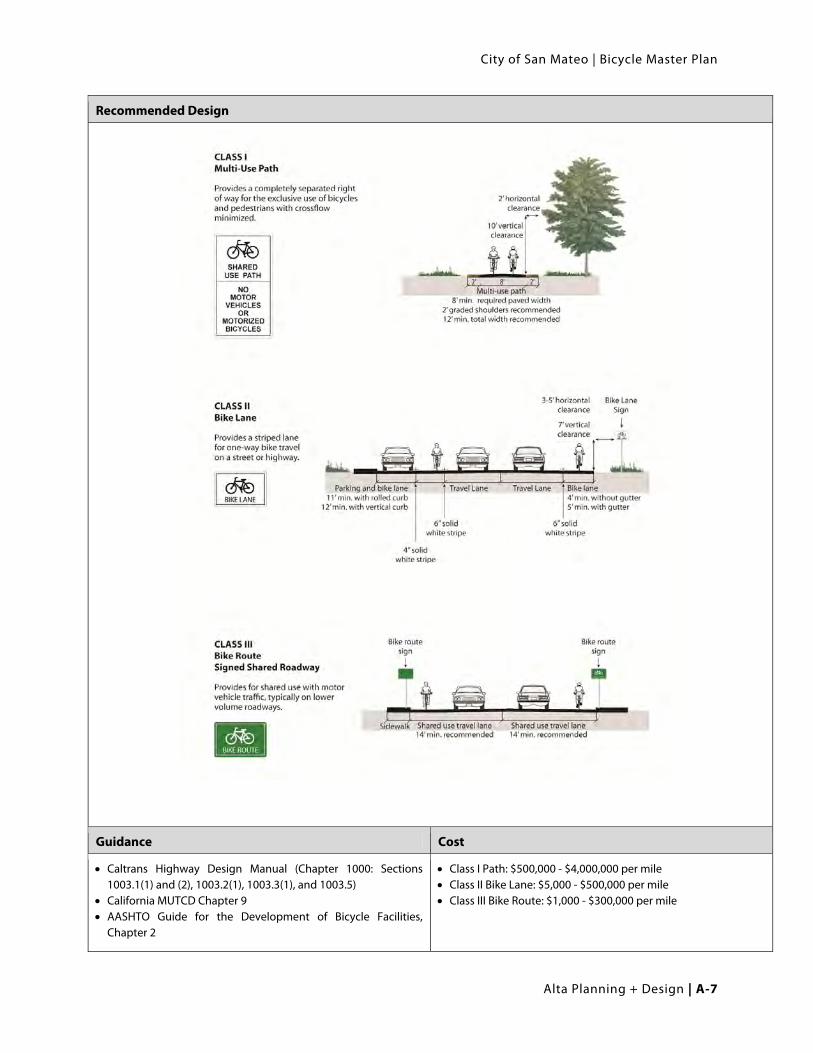
Caltrans has defined three types of bikeways in Chapter 1000 of the Highway Design Manual: Class I/shared use path, Class II/Bike Lane, and Class III/Bike Route. This document uses the generic terms “shared use path”, “bike lane” and “bike route”.
Class I Shared Use Bike Path
Class II Bike Lane
Class III Bike Route
Design Summary
Path Width:
8 feet is the minimum allowed for a two-way bicycle path and is only recommended for low traffic situations.
10 feet is recommended in most situations and will be adequate for moderate to heavy use.
12 feet is recommended for heavy use situations with high concentrations of multiple users such as joggers, bicyclists, rollerbladers and pedestrians. A separate track (5’ minimum) can be provided for pedestrian use.
Bike Lane Width with Adjacent On-Street Parking:
5 feet minimum recommended when parking stalls are marked
Bike Lane Width without Adjacent Parking:
4 feet minimum when no gutter is present (rural road sections)
5 feet minimum when adjacent to curb and gutter (3’ more than the gutter pan width if the gutter pan is greater than 2’)
Recommended Width: 6 feet where right-of-way allows
Lane Width for Bicycle Route With Wide Outside Lane:
Fourteen feet (14’) minimum is preferred. Fifteen feet (15’) should be considered if heavy truck or bus traffic is present. Bike lanes should be considered on roadways with outside lanes wider than 15 feet.
Sign Spacing
Bikeway signs shall be installed at the beginning of bikeways and at every decision point (intersection). Signs should be placed at every decision point and at quarter mile intervals. End signs may be placed at the end of bikeways.
City of San Mateo | Bicycle Master Plan
Alta Planning + Design | A-7
Recommended Design
Guidance Cost
Caltrans Highway Design Manual (Chapter 1000: Sections 1003.1(1) and (2), 1003.2(1), 1003.3(1), and 1003.5)
California MUTCD Chapter 9 AASHTO Guide for the Development of Bicycle Facilities,
Chapter 2
Class I Path: $500,000 - $4,000,000 per mile Class II Bike Lane: $5,000 - $500,000 per mile Class III Bike Route: $1,000 - $300,000 per mile
Appendix A | Design Guidelines
A-8 | Alta Planning + Design
A.3. Shared Use Paths A shared use path (Class I) allows for two-way, off-street bicycle use and also may be used by pedestrians,
skaters, wheelchair users, joggers and other non-motorized users. These facilities are frequently found in
parks, along rivers, beaches, and in greenbelts or utility corridors where there are few conflicts with
motorized vehicles. Class I facilities can also include amenities such as lighting, signage, and fencing (where
appropriate).
A.3.1. General Design Practices: Both the California Highway Design Manual Chapter 1000 and the AASHTO Guide for the Development of
Bicycle Facilities generally recommend against the development of shared use paths directly adjacent to
roadways. Also known as “sidepaths,” these facilities create a situation where a portion of the bicycle traffic
rides against the normal flow of motor vehicle traffic and can result in wrong-way riding when either entering
or exiting the path. This can also result in an unsafe situation where motorists entering or crossing the
roadway at intersections and driveways do not notice bicyclists coming from their right, as they are not
expecting traffic coming from that direction. Stopped cross-street motor vehicle traffic or vehicles exiting
side streets or driveways may frequently block path crossings. Even bicyclists coming from the left may also
go unnoticed, especially when sight distances are poor.
Shared use paths may be considered along roadways under the following conditions:
The path will generally be separated from all motor vehicle traffic.
Bicycle and pedestrian use is anticipated to be high.
In order to provide continuity with an existing path through a roadway corridor.
In order to direct bicycle and pedestrian traffic away from freeway ramps
The path can be terminated at each end onto streets with good bicycle facilities, or onto another well-
designed path.
There is adequate access to local cross-streets and other facilities along the route.
As bicyclists gain experience and realize some of the advantages of riding on the roadway, many stop riding on
paths adjacent to roadways. Bicyclists may also tend to prefer the roadway as pedestrian traffic on the bicycle
path increases due to its location next to an urban roadway. When designing a bikeway network, the
presence of a nearby or parallel path should not be used as a reason to not provide adequate shoulder or
bicycle lane width on the roadway, as the on-street bicycle facility will generally be superior to the “sidepath”
for experienced bicyclists and those who are cycling for transportation purposes. Bicycle lanes should be
provided as an alternate (more transportation-oriented) facility whenever possible.

City of San Mateo | Bicycle Master Plan
Alta Planning + Design | A-9
A.3.2. Pathway Design
Discussion Recommended Design
Ten-foot wide paved paths are usually best for accommodating all uses, and better for long-term maintenance and emergency vehicle access. When motor vehicles are driven on shared use paths, their wheels often will be at or very near the edges of the path. Since this can cause edge damage that, in turn, will reduce the effective operating width of the path, adequate edge support should be provided. Edge support can be either in the form of stabilized shoulders, a concrete “ribbon curb” along one or more edges of the path, or constructing additional pavement width or thickness. Constructing a typical pavement width of 10 feet, where right-of-way and other conditions permit, lessens the edge raveling problem.
Surfacing and Path Construction Thicker surfacing and a well-prepared sub-grade will reduce deformation over time and reduce long-term maintenance costs. At a minimum, off-street paths should be designed with sufficient surfacing structural depth for the sub-grade soil type to support maintenance and emergency vehicles.
Asphalt and concrete are the most common surface treatment for multi-use paths, however the material composition and construction methods used can have a significant determination on the longevity of the pathway. Surface selection should take place during the design process.
If trees are adjacent to the path, a root barrier should be installed along the path to avoid root uplift.
Appendix A | Design Guidelines
A-10 | Alta Planning + Design
Design Summary Design Example
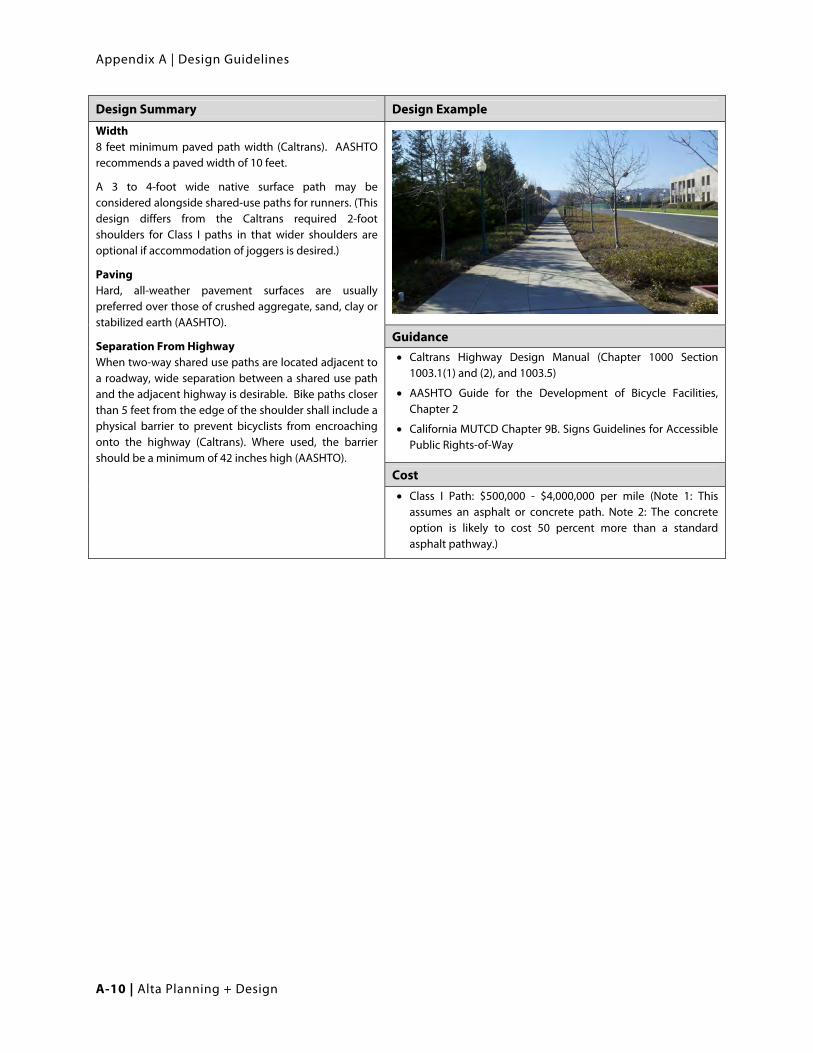
Width 8 feet minimum paved path width (Caltrans). AASHTO recommends a paved width of 10 feet.
A 3 to 4-foot wide native surface path may be considered alongside shared-use paths for runners. (This design differs from the Caltrans required 2-foot shoulders for Class I paths in that wider shoulders are optional if accommodation of joggers is desired.)
Paving Hard, all-weather pavement surfaces are usually preferred over those of crushed aggregate, sand, clay or stabilized earth (AASHTO).
Separation From Highway When two-way shared use paths are located adjacent to a roadway, wide separation between a shared use path and the adjacent highway is desirable. Bike paths closer than 5 feet from the edge of the shoulder shall include a physical barrier to prevent bicyclists from encroaching onto the highway (Caltrans). Where used, the barrier should be a minimum of 42 inches high (AASHTO).
Guidance Caltrans Highway Design Manual (Chapter 1000 Section
1003.1(1) and (2), and 1003.5)
AASHTO Guide for the Development of Bicycle Facilities, Chapter 2
California MUTCD Chapter 9B. Signs Guidelines for Accessible Public Rights-of-Way
Cost Class I Path: $500,000 - $4,000,000 per mile (Note 1: This
assumes an asphalt or concrete path. Note 2: The concrete option is likely to cost 50 percent more than a standard asphalt pathway.)

City of San Mateo | Bicycle Master Plan
Alta Planning + Design | A-11
A.3.3. Bollards
Discussion Recommended Design
Minimize the use of bollards to avoid creating obstacles for bicyclists. Bollards, particularly solid bollards, have caused serious injury to bicyclists. The California MUTCD explains, “Such devices should be used only where extreme problems are encountered” (Section 9C.101). Instead, design the path entry and use signage to alert drivers that motor vehicles are prohibited.
Bollards are ether fixed or removable and may be flexible or rigid. Flexible bollards and posts are designed to give way on impact and can be used instead of steel or solid posts. Bollards are typically installed using one of two methods: 1) The bollard is set into concrete footing in the ground; and 2) the bollard is attached to the surface by mechanical means (mechanical anchoring or chemical anchor).
Barrier Post Striping
Flexible Bollards
Source: Lighthouse Bollards Source: Andian Sales
Removable Bollards
Source: Reliance Foundry Co. Ltd
Design Summary
Where removable bollards are used, the top of the mount point should be flush with the path’s surface so as not to create a hazard. Posts shall be permanently reflectorized for nighttime visibility and painted a bright color for improved daytime visibility.
Striping an envelope around the post is recommended.
When more than one post is used, an odd number of posts at 1.5m (5-foot) spacing is desirable. Wider spacing can allow entry by adult tricycles, wheelchair users and bicycles with trailers.
Guidance
MUTCD – California Supplement (Section 9C.101-CA)
AASHTO Guide for the Development of Bicycle Facilities Chapter 2
Cost
Bollard, fixed: $220 - $800 each
Bollard, removable: $680 - $940 each

Appendix A | Design Guidelines
A-12 | Alta Planning + Design
A.3.4. Recommended Path Signage
Discussion Recommended Design
Custom signage may be installed to guide trail users on proper trail etiquette (see graphic), especially in areas where conflicts are likely to occur. Because pedestrians typically travel at slower speeds than bicyclists, it is recommended that any signage direct pedestrians to walk on the right. Where signage is necessary, any of the three types of signage to the right are recommended as ways to encourage path users to yield to each other and to keep the paths clear.
A centerline marking is particularly beneficial in the following circumstances: A) Where there is heavy use; B) On curves with restricted sight distance; and C) Where the path is unlighted and nighttime riding is expected.
User Etiquette Signs along Multi-Use Paths
Design Summary
Signage The Shared-Use Path Restriction (R9-7) sign may be installed on facilities shared by pedestrians and bicyclists.
Guidance Cost
MUTCD, Sections 9B.12 and 9C.03
MUTCD – California Supplement, Section 9B.11 and 9C.03
AASHTO Guide for the Development of Bicycle Facilities, Chapter 2
Signs, trail regulation: $150 each
Signs, trail wayfinding / information: $500 - $2,000 each
City of San Mateo | Bicycle Master Plan
Alta Planning + Design | A-13
A.4. Pathway Crossing Shared use paths can intersect with roadways at midblock locations, or as part of a roadway-roadway
intersection. Common issues at intersections of shared use paths and roadways include:
Bicyclists entering or exiting the path may travel against motor vehicle traffic;
Motorists crossing the shared use path at driveways and intersections may not notice path users,
particularly path users coming from the right;
Stopped motor vehicle traffic or vehicles exiting side streets or driveways may block the path; and
Motorists may not expect or be able to yield to fast-moving bicyclists at the intersection.
A.4.1. Treatments Bicycle and pedestrian pathway designers and traffic engineers generally have four options for designing
multi-use pathway crossings. These include:
Option 1- Reroute to the nearest at-grade controlled intersection crossing;
Option 2- Create a new at-grade midblock crossing with traffic controls where the pathway intersects
with the roadway;
Option 3- Create a new unprotected midblock crossing where the pathway intersects with the
roadway; and
Option 4- Create a grade-separated undercrossing or overcrossing of the roadway where the pathway
intersects the roadway.

Appendix A | Design Guidelines
A-14 | Alta Planning + Design
A.4.2. Path Crossing at Intersection
Discussion Design Summary
The evaluation of a roadway crossing involves analysis of vehicular traffic and path user travel patterns, including speeds, street width, traffic volumes (average daily traffic, peak hour traffic), line of sight, and trail user profile (age distribution and destinations).
When engineering judgment determines that the visibility of the intersection is limited on the shared-use path approach, Intersection Warning signs should be used.
A path should be routed to a signalized intersection if the path would cross a major arterial with a high ADT within 350 feet of a signalized intersection. Signage Intersection Warning (W2-1 through W2-5) signs may be used on a roadway, street, or shared-use path in advance of an intersection to indicate the presence of an intersection and the possibility of turning or entering traffic. A trail-sized stop sign (R1-1) should be placed about 5 feet before the intersection.
Traffic Calming Reducing the speed of the conflicting motor vehicle traffic should be considered. Options may include: transverse rumble strips approaching the trail crossing or sinusoidal speed humps.
Crosswalk Markings Colored and/or high visibility crosswalks should be considered.
Path Speed Control A chicane, or swerve in multi-use path approaching the crossing is recommended to slow bicyclist speed. Path users traveling in different directions should be separated either with physical separation (bollard or raised median) or a centerline. If a centerline is used, it should be striped for the last 100 feet of the approach.

City of San Mateo | Bicycle Master Plan
Alta Planning + Design | A-15
Recommended Design
Recommended “Typical” At-Grade Crossing at an Intersection Where Trail is Adjacent to a Road

Appendix A | Design Guidelines
A-16 | Alta Planning + Design
Design Example Recommended Design (Continued)
Typical “at grade” roadway crossing.
Source: PBIC Image Library
Photographer: Danny McCullough
Recommended “Typical” At-Grade Crossing of a Major Arterial at an Intersection Where Trail is Within 350 Feet of a Roadway
Intersection
Guidance
Caltrans Highway Design Manual (Chapter 1000 Section 1003.1(4))
MUTCD – California Supplement, Part 9
AASHTO Guide for the Development of Bicycle Facilities and “A Policy on the Geometric Design of Highways and Streets”
FHWA-RD-87-038 Investigation of Exposure-Based Pedestrian Accident Areas: Crosswalks, Sidewalks, Local Streets, and Major Arterials.
Cost
Crosswalk, Transverse (parallel) Lines: $320 - $550 each
Crosswalk, Thermoplastic: $6 per square foot
Stop bar: $210 each
Stop Limit Bars / Yield Teeth: $210 - $530 each
Stop Pavement Markings: $420 each
Curb Ramps, Retrofit (diagonal, per corner): $800 – 5,340 each
Curb Ramps, Retrofit (perpendicular, per corner): $5,340 - $10,000 each
Signs, High-Visibility: $430 each
Bollard, fixed: $220 - $800 each
Bollard, removable: $680 - $940 each

City of San Mateo | Bicycle Master Plan
Alta Planning + Design | A-17
A.4.3. Uncontrolled Mid-Block Crossing
Discussion Recommended Design
The table on the following page is a summary for implementing at-grade roadway crossings in the City of San Mateo. The number one (1) indicates a ladder style crosswalk with appropriate signage is warranted. (1/1+) indicates the crossing warrants enhanced treatments such as flashing beacons, or in-pavement flashers. (1+/3) indicates Pedestrian Light Control Activated (Pelican), or Hawk signals should be considered.
Source: California MUTCD, Figure 3B-15
Design Summary
Placement Mid-block crosswalks should be installed where there is a significant demand for crossing and no nearby existing crosswalks.
Yield Lines
If yield lines are used for vehicles, they shall be placed 20 to 50 feet in advance of the nearest crosswalk line to indicate the point at which the yield is intended or required to be made and ‘Yield Here to Pedestrians’ signs shall be placed adjacent to the yield line. Where traffic is not heavy, stop or yield signs for pedestrians and bicyclists may suffice.
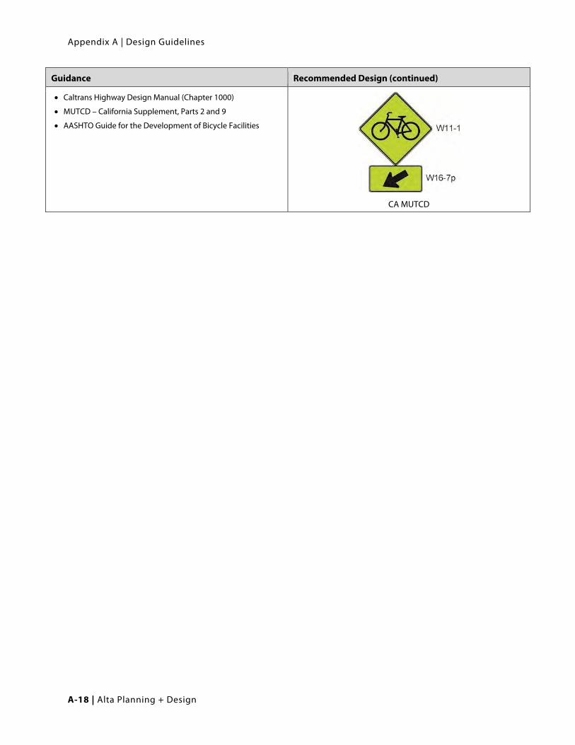
Warning Signs
The Bicycle Warning (W11-1) sign alerts the road user to unexpected entries into the roadway by bicyclists, and other crossing activities that might cause conflicts.
Pavement Markings A ladder crosswalk should be used. Warning markings on the path and roadway should be installed.
Other Treatments
See table on the following page to determine if treatments such as raised median refuges, flashing beacons should be used.
Beacons See Section A.4.4. of this document
Appendix A | Design Guidelines
A-18 | Alta Planning + Design
Guidance Recommended Design (continued)
Caltrans Highway Design Manual (Chapter 1000)
MUTCD – California Supplement, Parts 2 and 9
AASHTO Guide for the Development of Bicycle Facilities
CA MUTCD

City of San Mateo | Bicycle Master Plan
Alta Planning + Design | A-19
Table A-1: Crosswalk Decision Matrix
Roadway Type (Number of Travel
Lanes and
Median Type)
Vehicle ADT < 9,000
Vehicle ADT (> 9,000 to 12,000)
Vehicle ADT >12,000 to 15,000
Vehicle ADT > 15,000
Speed Limit**
<30 MPH
35 MPH
40 MPH
<30 MPH
35 MPH
40 MPH
<30 MPH
35 MPH
40 MPH
<30 MPH
35 MPH
40 MPH
2 Lanes 1 1 1/1+ 1 1 1/1+ 1 1 1+/3 1 1/1+ 1+/3
3 Lanes 1 1 1/1+ 1 1/1+ 1/1+ 1/1+ 1/1+ 1+/3 1/1+ 1+/3 1+/3
Multi-Lane (4 or more lanes ) with raised median***
1 1 1/1+ 1 1/1+ 1+/3 1/1+ 1/1+ 1+/3 1+/3 1+/3 1+/3
Multi-Lane (4 or more lanes) without raised median
1 1/1+ 1+/3 1/1+ 1/1+ 1+/3 1+/3 1+/3 1+/3 1+/3 1+/3 1+/3
*General Notes: Crosswalks should not be installed at locations that could present an increased risk to bicyclists and pedestrians,
such as where there is poor sigh distance, complex or confusing designs, a substantial volume of heavy trucks, or other dangers,
without first providing adequate design features and/or traffic control devices. Adding crosswalks alone will not make crossing
safer, nor will they necessarily result in more vehicles stopping for bicyclists and pedestrians. Whether or not marked crosswalks
are installed, it is important to consider other facility enhancements (e.g. raised median, traffic signal, roadway narrowing,
enhanced overhead lighting, traffic-calming measures, curb extensions), as needed, to improve the safety of the crossing. These
are general recommendations; good engineering judgment should be used in individual cases for deciding which treatment to
use. For each trail-road way crossing, an engineering study is needed to determine the proper location. For each engineering
study, a site review may be sufficient at some locations, while a more in-depth study of pedestrian volume, vehicle speed, sight
distance, vehicle mix, etc. may be needed at other sites.
**Where the speed limit exceeds 40 MPH (64.4 km/h), marked crosswalks alone should not be used at unsignalized locations.
***The raised median or crossing island must be at least 4 ft (1.2 m) wide and 6 ft (1.8 m long) to adequately serve as a refuge
area for pedestrians in accordance with MUTCD and AASHTO guidelines. A two-way center turn lane is not considered a median.
1 = Type 1 Crossings. Ladder-style crosswalks with appropriate signage should be used.
1/1+ = With the higher volumes and speeds, enhanced treatments should be used, including marked ladder style crosswalks,
median refuge, flashing beacons, and/or in-pavement flashers. Ensure there are sufficient gaps through signal timing, as well as
sight distance.
1+/3 = Carefully analyze signal warrants using a combination of Warrant 2 or 5 (depending on school presence) and EAU
factoring. Make sure to project usage based on future potential demand. Consider Pelican or Hawk signals in lieu of full signals.
For those intersections not meeting warrants or where engineering judgment or cost recommends against signalization,
implement Type 1 enhanced crosswalk markings with marked ladder style crosswalks, median refuge, flashing beacons, and/or
in-pavement flashers. Ensure there are sufficient gaps through signal timing, as well as sight distance.
Appendix A | Design Guidelines
A-20 | Alta Planning + Design
A.4.4. Crossing Beacons
Discussion Recommended Design
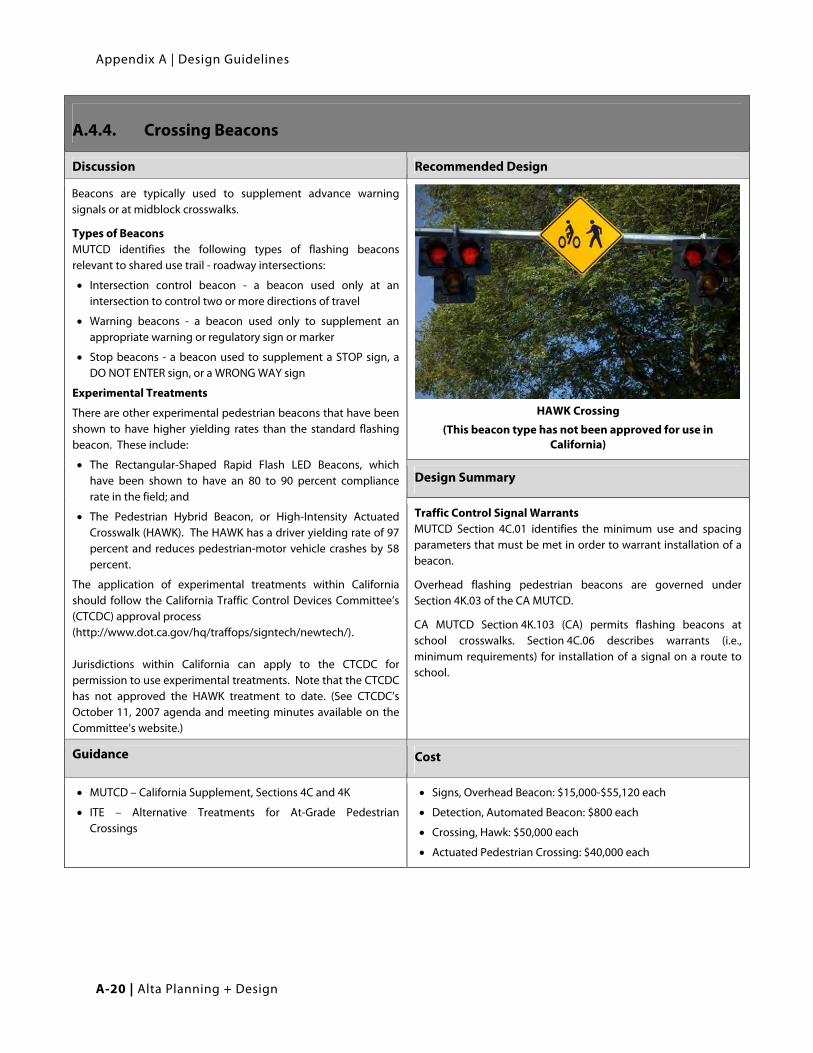
Beacons are typically used to supplement advance warning signals or at midblock crosswalks.
Types of Beacons MUTCD identifies the following types of flashing beacons relevant to shared use trail - roadway intersections:
Intersection control beacon - a beacon used only at an intersection to control two or more directions of travel
Warning beacons - a beacon used only to supplement an appropriate warning or regulatory sign or marker
Stop beacons - a beacon used to supplement a STOP sign, a DO NOT ENTER sign, or a WRONG WAY sign
Experimental Treatments
There are other experimental pedestrian beacons that have been shown to have higher yielding rates than the standard flashing beacon. These include:
The Rectangular-Shaped Rapid Flash LED Beacons, which have been shown to have an 80 to 90 percent compliance rate in the field; and
The Pedestrian Hybrid Beacon, or High-Intensity Actuated Crosswalk (HAWK). The HAWK has a driver yielding rate of 97 percent and reduces pedestrian-motor vehicle crashes by 58 percent.
The application of experimental treatments within California should follow the California Traffic Control Devices Committee’s (CTCDC) approval process (http://www.dot.ca.gov/hq/traffops/signtech/newtech/). Jurisdictions within California can apply to the CTCDC for permission to use experimental treatments. Note that the CTCDC has not approved the HAWK treatment to date. (See CTCDC’s October 11, 2007 agenda and meeting minutes available on the Committee’s website.)
HAWK Crossing
(This beacon type has not been approved for use in California)
Design Summary
Traffic Control Signal Warrants MUTCD Section 4C.01 identifies the minimum use and spacing parameters that must be met in order to warrant installation of a beacon.
Overhead flashing pedestrian beacons are governed under Section 4K.03 of the CA MUTCD.
CA MUTCD Section 4K.103 (CA) permits flashing beacons at school crosswalks. Section 4C.06 describes warrants (i.e., minimum requirements) for installation of a signal on a route to school.
Guidance Cost
MUTCD – California Supplement, Sections 4C and 4K
ITE – Alternative Treatments for At-Grade Pedestrian Crossings
Signs, Overhead Beacon: $15,000-$55,120 each
Detection, Automated Beacon: $800 each
Crossing, Hawk: $50,000 each
Actuated Pedestrian Crossing: $40,000 each
City of San Mateo | Bicycle Master Plan
Alta Planning + Design | A-21
A.4.5. Signalized Mid-Block Crossing
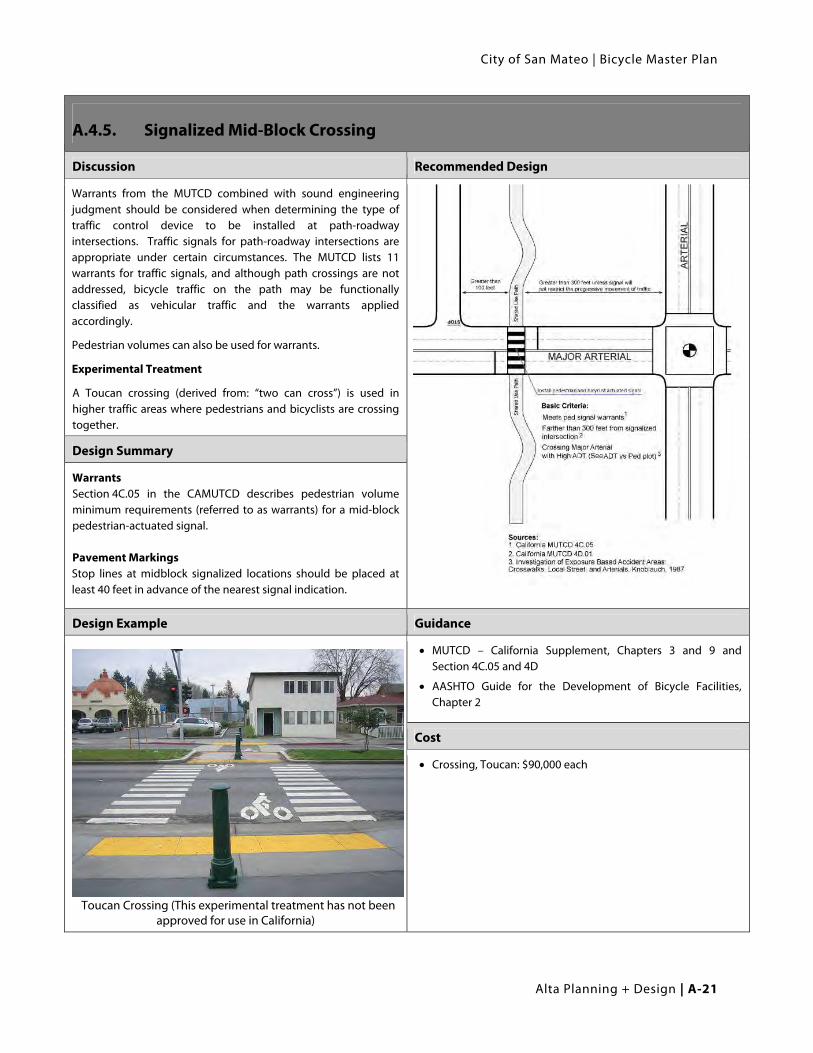
Discussion Recommended Design
Warrants from the MUTCD combined with sound engineering judgment should be considered when determining the type of traffic control device to be installed at path-roadway intersections. Traffic signals for path-roadway intersections are appropriate under certain circumstances. The MUTCD lists 11 warrants for traffic signals, and although path crossings are not addressed, bicycle traffic on the path may be functionally classified as vehicular traffic and the warrants applied accordingly.
Pedestrian volumes can also be used for warrants.
Experimental Treatment
A Toucan crossing (derived from: “two can cross”) is used in higher traffic areas where pedestrians and bicyclists are crossing together.
Design Summary
Warrants Section 4C.05 in the CAMUTCD describes pedestrian volume minimum requirements (referred to as warrants) for a mid-block pedestrian-actuated signal. Pavement Markings Stop lines at midblock signalized locations should be placed at least 40 feet in advance of the nearest signal indication.
Design Example Guidance
Toucan Crossing (This experimental treatment has not been approved for use in California)
MUTCD – California Supplement, Chapters 3 and 9 and Section 4C.05 and 4D
AASHTO Guide for the Development of Bicycle Facilities, Chapter 2
Cost
Crossing, Toucan: $90,000 each
Appendix A | Design Guidelines
A-22 | Alta Planning + Design
A.5. On-Street Bicycle Facility Design
A.5.1. Bike Lanes Bike lanes or Class II bicycle facilities (Caltrans designation) are defined as a portion of the roadway that has
been designated by striping, signage, and pavement markings for the preferential or exclusive use of bicyclists.
Bike lanes are generally found on major arterial and collector roadways and are 4 to 7 feet wide. Bike lanes can
be found in a large variety of configurations, and can even incorporate special characteristics including
coloring and placement, if beneficial.
Bike lanes enable bicyclists to ride at their preferred speed without interference from prevailing traffic
conditions and facilitate predictable behavior and movements between bicyclists and motorists. Bicyclists
may leave the bike lane to pass other bicyclists, make left turns, avoid obstacles or debris, and to avoid other
conflicts with other roadway users.
A.5.2. General Design Guidance:
A.5.2.1. Width: Varies depending on roadway configuration, see following pages for design examples.
A.5.2.2. Striping:
Line separating vehicle lane from bike lane (typically left sideline): 6 inches
Line separating bike lane from parking lane (if applicable): 4 inches
Dashed white stripe when:
Vehicle merging area: Varies
Delineate conflict area in intersections(optional): Length of conflict area
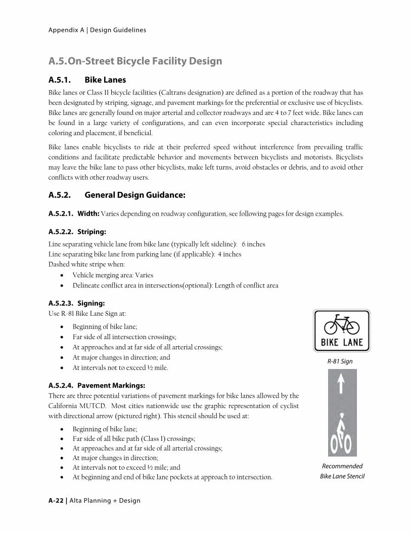
A.5.2.3. Signing: Use R-81 Bike Lane Sign at:
Beginning of bike lane;
Far side of all intersection crossings;
At approaches and at far side of all arterial crossings;
At major changes in direction; and
At intervals not to exceed ½ mile.
A.5.2.4. Pavement Markings: There are three potential variations of pavement markings for bike lanes allowed by the
California MUTCD. Most cities nationwide use the graphic representation of cyclist
with directional arrow (pictured right). This stencil should be used at:
Beginning of bike lane; Far side of all bike path (Class I) crossings; At approaches and at far side of all arterial crossings; At major changes in direction; At intervals not to exceed ½ mile; and At beginning and end of bike lane pockets at approach to intersection.
R-81 Sign
Recommended Bike Lane Stencil

City of San Mateo | Bicycle Master Plan
Alta Planning + Design | A-23
A.5.3. Bike Lane with No On-Street Parking
Discussion Recommended Design
Recommended bicycle lane width is 5 feet minimum when adjacent to curb and gutter. Wider bicycle lanes are desirable in certain circumstances such as on higher speed arterials (45 mph+) where a wider bicycle lane can increase separation between passing vehicles and bicyclists, which is especially preferable on uphill grades. Appropriate signing and stenciling is important with wide bicycle lanes to ensure motorists do not mistake the lane for a vehicle lane or parking lane. Bicycle lanes wider than seven feet are not recommended.
Design Summary
Bike Lane Width:
4 feet minimum when no gutter is present (rural road sections)
5 feet minimum when adjacent to curb and gutter (3’ more than the gutter pan width if the gutter pan is greater than 2’)
Recommended Width:
6 feet where right-of-way allows and up hills
Guidance Cost
MUTCD
Caltrans Highway Design Manual (Chapter 1000)
MUTCD – California Supplement
AASHTO Guide for the Development of Bicycle Facilities
Class II Bike Lane: $5,000-$500,000 per mile

Appendix A | Design Guidelines
A-24 | Alta Planning + Design
A.5.4. Bike Lane With On-Street Parallel Parking
Discussion Recommended Design
Bike lanes adjacent to parallel parking should be designed to be wide enough to allow bicyclists to ride outside of the “door zone” (i.e., five feet minimum).
Design Summary
Bike Lane Width:
5 feet minimum recommended when parking stalls are marked
7 feet maximum (wider lanes may encourage vehicle loading in bike lane)
12 feet for a shared lane adjacent to a curb face (13 feet is preferred where parking is substantial or turnover is high), or 11’ minimum for a shared bike/parking lane on streets without curbs where parking is permitted.
Guidance Cost
Caltrans Highway Design Manual (Chapter 1000)
MUTCD – California Supplement
AASHTO Guide for the Development of Bicycle Facilities
Class II Bike Lane: $5,000-$500,000 per mile

City of San Mateo | Bicycle Master Plan
Alta Planning + Design | A-25
A.6. Bike Routes Bike routes, or Class III bicycle facilities – (Caltrans designation) are defined as facilities shared with motor
vehicles. They are typically used on roads with low speeds and traffic volumes, however can be used on higher
volume roads with wide outside lanes or with shoulders. Bike routes can be established along through routes
not served by shared use paths (Class I) or bike lanes (Class II), or to connect discontinuous segments of
bikeway. A motor vehicle driver will usually have to cross over into the adjacent travel lane to pass a bicyclist,
unless a wide outside lane or shoulder is provided.
Bicycle Routes can employ a large variety of treatments from simple signage to complex treatments including
various types of traffic calming and/or pavement stenciling. The level of treatment to be provided for a specific
location or corridor depends on several factors.
A.6.1. General Design Guidance:
A.6.1.1. Signing: Use D11-1 Bicycle Route Sign at:
Beginning or end of bicycle route (with applicable M4 series sign);
Entrance to bicycle path (Class I) – optional;
At major changes in direction or at intersections with other bicycle routes
(with applicable M7 series sign); and
At intervals along bicycle routes not to exceed ½ mile.
A.6.1.2. Pavement Markings: Shared Lane Markings may be applied to bicycle routes per Section A.6.3.
D11-1 Sign

Appendix A | Design Guidelines
A-26 | Alta Planning + Design
A.6.2. Bike Route
Discussion Recommended Design
Bicycle routes on local streets should have vehicle traffic volumes under 1,000 vehicles per day. Traffic calming may be appropriate on streets that exceed this limit.
Bicycle routes may be placed on streets with outside lane width of less than 15 feet if vehicle speeds and volumes are low.
Design Summary
Bicycle Route signage may include City specific logos. See design example below.
Route signage should be applied at intervals frequent enough to keep bicyclists informed of changes in route direction and to remind motorists of the presence of bicyclists.
Design Example
Guidance
Caltrans Highway Design Manual (Chapter 1000)
MUTCD – California Supplement
AASHTO Guide for the Development of Bicycle Facilities
Cost
Class III Bike Route: $1,000-$40,000 per mile (assumes no major renovation is required)
$150,000 - $300,000 (assuming moderate to major roadway renovation)

City of San Mateo | Bicycle Master Plan
Alta Planning + Design | A-27
A.6.3. Class III Bike Route with Shared Lane Markings (SLM)
Discussion Recommended Design
Recently, Shared Lane Marking (SLM) stencils (also called “Sharrows”) have been introduced for use in California as an additional treatment for bike route (Class III) facilities and are currently approved in conjunction with on-street parking. The stencil can serve a number of purposes, such as making motorists aware of the need to share the road with bicyclists, showing bicyclists the direction of travel, and, with proper placement, reminding bicyclists to bike further from parked cars to prevent “dooring” collisions.
The 2010 California MUTCD specifies that SLM only be used on roadways with parallel parking, but the forthcoming 2011 edition will give local engineers greater discretion with SLM placement on roadways with or without parking.
SLM should be placed a minimum of 11 feet from the curb. Where there are two or more travel lanes per direction, if the outside lane is less than 14 feet, or where there is high parking turnover or where bicyclists may need positioning guidance, the SLM may be placed in the middle of the outside travel lane. Additionally SLM’s may be placed where drivers may need additional notice to expect bicyclists.
Though not always possible, placing the SLM markings outside of vehicle tire tracks will increase the life of the markings and the long-term cost of the treatment.
Design Summary
Door Zone Width:
The width of the door zone is generally assumed to be 2.5 feet from the edge of the parking lane.
Recommended SLM placement:
A Minimum of 11.5 feet from edge of curb where on-street parking is present.
Where there are two or more travel lanes per direction, if the outside lane is less than 14 feet, or where there is high parking turnover or where bicyclists may need positioning guidance, the SLM may be placed in the middle of the outside travel lane.
Guidance
MUTCD – California Supplement, Section 9C.103
Cost
Stencils only: $250 each

Appendix A | Design Guidelines
A-28 | Alta Planning + Design
A.6.4. Additional Bike Route Signage
Discussion Recommended Design
‘Share the Road’ signs are intended to ‘reduce motor vehicle/bicyclist conflict’ and are appropriate to be placed on routes that lack paved shoulders or other bicycle facilities. They typically work best in rural situations, or when placed near activity centers such as schools, shopping centers and other destinations that attract bicycle traffic.
In urban areas, many cities around the country have been experimenting with a new type of signage that encourages bicyclists to take the lane when the lane is too narrow. This type of sign is becoming known as BAUFL (Bikes Allowed Use of Full Lane). This can be quantified to lanes being less than 14 feet wide with no parking and less than 22 feet wide with adjacent parallel parking. The 2009 update to the MUTCD recognizes the need for such signage and has designated the white and black sign at right (R4-11). The 2010 CA MUTCD states that Shared Lane Markings (which serve a similar function as Bikes May Use Full Lane signage) should not be placed on roadways that have a speed limit above 40 mph. Dedicated bicycle facilities are recommended for roadways with speed limits above 40 mph where the need for bicycle access exists.
Share The Road Signs
CA MUTCD Sign R4-11
Design Summary
Placement:
Signs should be placed at regular intervals along routes with no designated bicycle facilities.
Guidance
MUTCD – California Supplement Section 9C.103
Cost
Sign, regulation: $150 each

City of San Mateo | Bicycle Master Plan
Alta Planning + Design | A-29
A.6.5. Bicycle Boulevards
Discussion Design Example
Bicycle boulevards have been implemented in a variety of locations including Palo Alto, San Luis Obispo, Berkeley and Davis, California and Portland, Oregon. Bicycle boulevards, also known as bicycle priority streets, are non-arterial streets that are designed to allow bicyclists to travel at a consistent, comfortable speed along low-traffic roadways and to cross arterials conveniently and safely. Bicycle boulevards typically include treatments that allow bicyclists to travel along the bicycle boulevard with minimal stopping while discouraging motor vehicle traffic. Traffic calming and traffic management treatments such as traffic circles, chicanes, and diverters are used to discourage motor vehicles from speeding and using the bicycle boulevard as a cutthrough. Quick-response traffic signals, median islands, or other crossing treatments are provided to facilitate bicycle crossings of arterial roadways.
See next page.
Design Summary
Residential streets with low traffic volumes (typically between 3000 to 5000 average daily vehicles).
Can include secondary commercial streets.
Bicycle boulevard pavement markings should be installed in conjunction with wayfinding signs.
Can be designed to accommodate the particular needs of the residents and businesses along the routes, and may be as simple as pavement markings with wayfinding signs or as complex as a street with traffic diverters and bicycle signals.
Guidance
This treatment is not currently present in any State or Federal design standards
Berkeley Bicycle Boulevard Design Tools and Guidelines: http://www.ci.berkeley.ca.us/ContentDisplay.aspx?id=6652
Cost
$310,500 per mi (source: San Benito Bike Plan, 2008)

Appendix A | Design Guidelines
A-30 | Alta Planning + Design
City of San Mateo | Bicycle Master Plan
Alta Planning + Design | A-31
A.6.6. Buffered Bike Lanes
Discussion Recommended Design
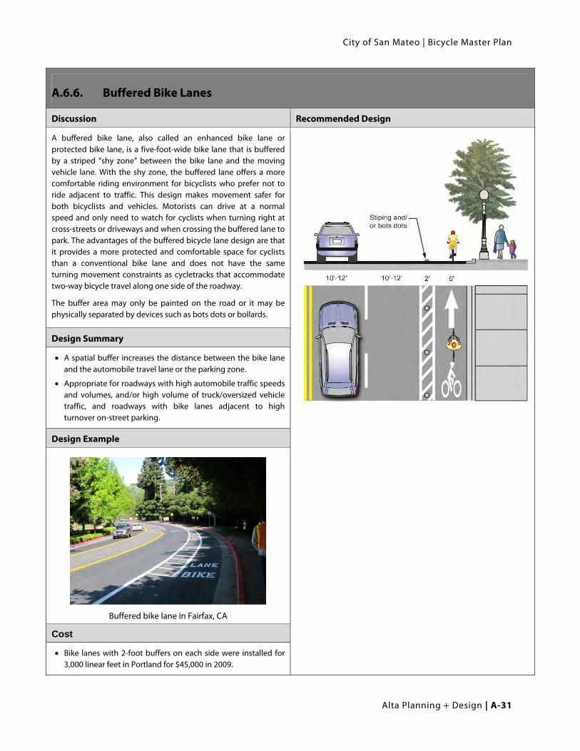
A buffered bike lane, also called an enhanced bike lane or protected bike lane, is a five-foot-wide bike lane that is buffered by a striped “shy zone” between the bike lane and the moving vehicle lane. With the shy zone, the buffered lane offers a more comfortable riding environment for bicyclists who prefer not to ride adjacent to traffic. This design makes movement safer for both bicyclists and vehicles. Motorists can drive at a normal speed and only need to watch for cyclists when turning right at cross-streets or driveways and when crossing the buffered lane to park. The advantages of the buffered bicycle lane design are that it provides a more protected and comfortable space for cyclists than a conventional bike lane and does not have the same turning movement constraints as cycletracks that accommodate two-way bicycle travel along one side of the roadway.
The buffer area may only be painted on the road or it may be physically separated by devices such as bots dots or bollards.
Design Summary
A spatial buffer increases the distance between the bike lane and the automobile travel lane or the parking zone.
Appropriate for roadways with high automobile traffic speeds and volumes, and/or high volume of truck/oversized vehicle traffic, and roadways with bike lanes adjacent to high turnover on-street parking.
Design Example
Buffered bike lane in Fairfax, CA
Cost
Bike lanes with 2-foot buffers on each side were installed for 3,000 linear feet in Portland for $45,000 in 2009.

Appendix A | Design Guidelines
A-32 | Alta Planning + Design
A.6.7. Colored Bike Lanes
Discussion Recommended Design
Color applied to bike lanes helps alert roadway users to the presence of bicyclists and clearly assigns right-of-way to cyclists. Motorists are expected to yield to cyclists in these areas. Some cities apply color selectively to highlight potential conflict zones, while others use it to mark all non-shared bicycle facilities in high volume traffic situations.
Color Considerations:
There are three colors commonly used in bicycle lanes: blue, green, and red. All help the bike lane stand out in merging areas. The City of Portland began using green lanes in 2008, as blue, the color used previously, is a color associated with ADA related signage on roadways. Green is the color recommended for use in the City of San Mateo.
Material Options:
Colored bike lanes require additional cost to install and maintain. Techniques include:
Paint – less durable and can be slippery when wet
Colored asphalt – colored medium in asphalt during construction – most durable.
Colored and textured sheets of acrylic epoxy coating.
Colored bike lanes used to designate a conflict zone
Design Summary
Bike lane width: See Section A.5.
Appropriate for heavy auto traffic streets with bike lanes; at transition points where cyclists, motorists and/or pedestrians must weave with one another; conflict areas or intersections with a record of crashes; and to emphasize bicycle space in unfamiliar or unique design treatments.
Design Example Guidance
FHWA provides blanked approval for green colored pavement in marked bike lanes and bike lane extensions.
Caltrans has approval (IA-14.10 – Green Colored Pavement for Bike Lanes – California Statewide).
Agencies that use this treatment must provide location to the CTCDC.

City of San Mateo | Bicycle Master Plan
Alta Planning + Design | A-33
A.6.8. Manholes & Drainage Grates
Discussion Recommended Design
Utility infrastructure within the roadway can present significant hazards to bicyclists. Manholes, water valve covers, drain inlets and other obstructions can present an abrupt change in level, or present a situation where the bicyclist’s tire could become stuck, potentially creating an accident. As such, every effort should be made to locate such hazards outside of the likely travel path of bicyclists on new roadway construction.
For existing roadways, the roadway surface can be ground down around the manhole or drainage grate to be no more than half an inch of vertical drop. When roadways undergo overlays, this step is often omitted and significant elevation differences can result in hazardous conditions for bicyclists.
Bicycle drainage grates should not have longitudinal slats that can catch a bicycle tire and potentially cause an accident. Acceptable grate designs are presented (top right) as A: patterned, B: transverse grate, or C: modified longitudinal with no more than 6” between transverse supports). Type C is the least desirable as it could still cause problems with some bicycle tires. The drop in-inlet avoids all issues with grates in the bicyclists’ line of travel, however, these drainage inlets are not recommended by Caltrans for use on California Highways. The CA MUTCD recommends providing a diagonal solid white line for hazards or obstructions in bikeways (see right).
Bicycle Compatible Drainage Grates
Drop-in inlet flush with in the curb face (Oregon DOT)
Figure 9C-8
Design Summary
Placement:
Manholes should be placed outside of any bike lanes. Drainage grates should be of one of the types at right.
Guidance
Caltrans Highway Design Manual (Chapter 1000)
MUTCD – California Supplement
AASHTO Guide for the Development of Bicycle Facilities
Cost
Striping: $2 per linear foot
Drainage grate: $500
Appendix A | Design Guidelines
A-34 | Alta Planning + Design
A.6.9. Bicycle Access During Construction Activities
Discussion Recommended Design
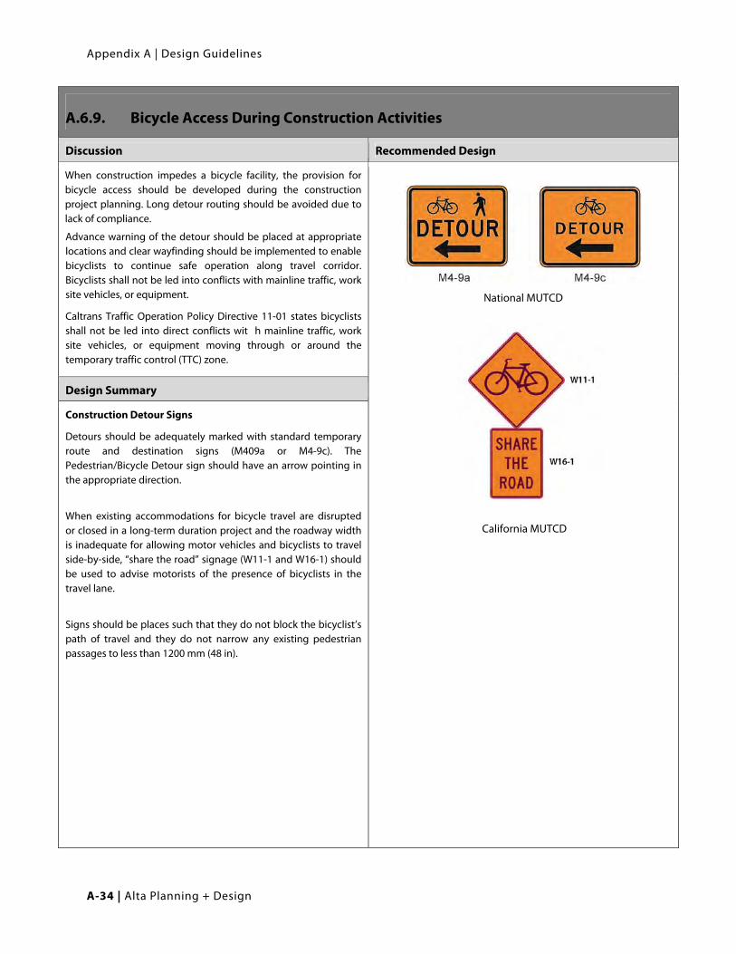
When construction impedes a bicycle facility, the provision for bicycle access should be developed during the construction project planning. Long detour routing should be avoided due to lack of compliance.
Advance warning of the detour should be placed at appropriate locations and clear wayfinding should be implemented to enable bicyclists to continue safe operation along travel corridor. Bicyclists shall not be led into conflicts with mainline traffic, work site vehicles, or equipment.
Caltrans Traffic Operation Policy Directive 11-01 states bicyclists shall not be led into direct conflicts wit h mainline traffic, work site vehicles, or equipment moving through or around the temporary traffic control (TTC) zone.
National MUTCD
California MUTCD
Design Summary
Construction Detour Signs
Detours should be adequately marked with standard temporary route and destination signs (M409a or M4-9c). The Pedestrian/Bicycle Detour sign should have an arrow pointing in the appropriate direction.
When existing accommodations for bicycle travel are disrupted or closed in a long-term duration project and the roadway width is inadequate for allowing motor vehicles and bicyclists to travel side-by-side, “share the road” signage (W11-1 and W16-1) should be used to advise motorists of the presence of bicyclists in the travel lane.
Signs should be places such that they do not block the bicyclist’s path of travel and they do not narrow any existing pedestrian passages to less than 1200 mm (48 in).

City of San Mateo | Bicycle Master Plan
Alta Planning + Design | A-35
Design Example Guidance
California MUTCD – Part 6
California Highway Design Manual
Caltrans Traffic Operations Policy Directive 11-01
Cost
Sign, regulation: $150 each
Appendix A | Design Guidelines
A-36 | Alta Planning + Design
A.7. Intersection and Interchange Design for Bicyclists Adequately accommodating bicyclists at traffic intersections and interchanges can be challenging for traffic engineers
as the needs and characteristics of bicycles and motor vehicles vary greatly. This chapter contains sections on
detection of bicycles at signals, bicycle pavement markings at signals, and bicycle signals.
A.7.1. Bicycle Detection at Signalized Intersections
Discussion Recommended Design
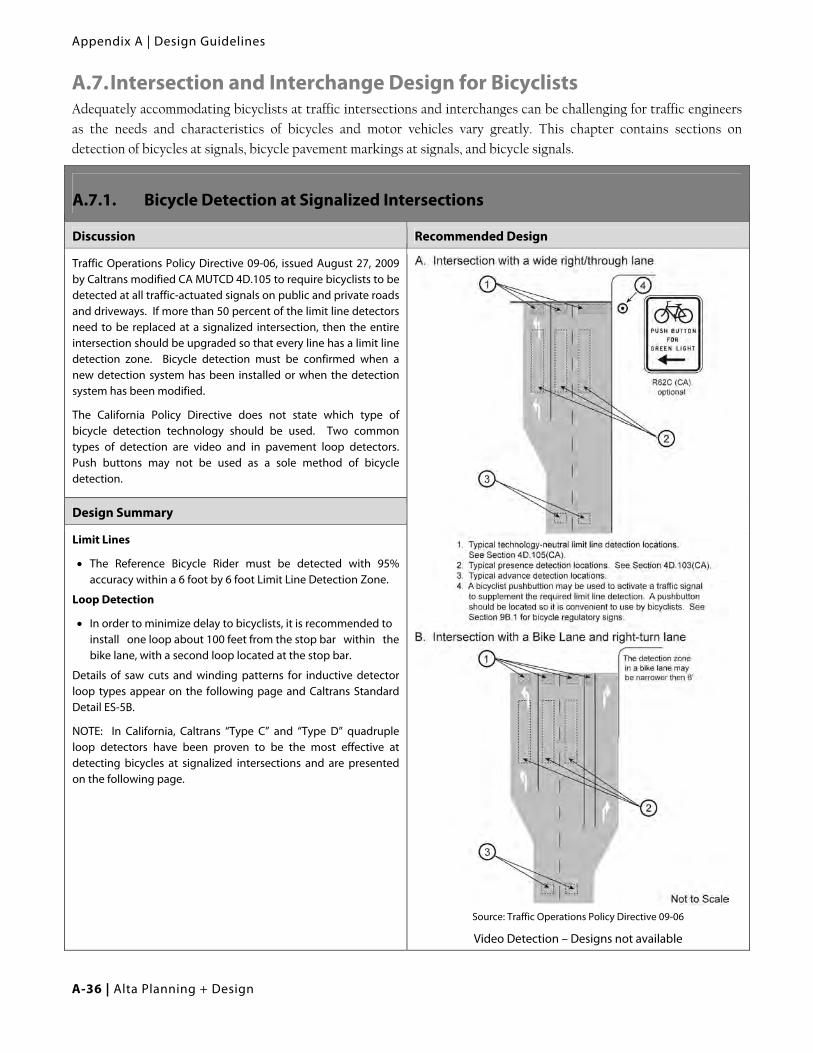
Traffic Operations Policy Directive 09-06, issued August 27, 2009 by Caltrans modified CA MUTCD 4D.105 to require bicyclists to be detected at all traffic-actuated signals on public and private roads and driveways. If more than 50 percent of the limit line detectors need to be replaced at a signalized intersection, then the entire intersection should be upgraded so that every line has a limit line detection zone. Bicycle detection must be confirmed when a new detection system has been installed or when the detection system has been modified.
The California Policy Directive does not state which type of bicycle detection technology should be used. Two common types of detection are video and in pavement loop detectors. Push buttons may not be used as a sole method of bicycle detection.
Source: Traffic Operations Policy Directive 09-06
Video Detection – Designs not available
Design Summary
Limit Lines
The Reference Bicycle Rider must be detected with 95% accuracy within a 6 foot by 6 foot Limit Line Detection Zone.
Loop Detection
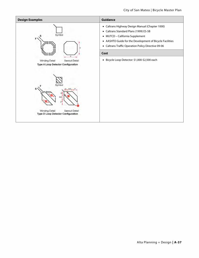
In order to minimize delay to bicyclists, it is recommended to install one loop about 100 feet from the stop bar within the bike lane, with a second loop located at the stop bar.
Details of saw cuts and winding patterns for inductive detector loop types appear on the following page and Caltrans Standard Detail ES-5B.
NOTE: In California, Caltrans “Type C” and “Type D” quadruple loop detectors have been proven to be the most effective at detecting bicycles at signalized intersections and are presented on the following page.
City of San Mateo | Bicycle Master Plan
Alta Planning + Design | A-37
Design Examples Guidance
Caltrans Highway Design Manual (Chapter 1000)
Caltrans Standard Plans (1999) ES-5B
MUTCD – California Supplement
AASHTO Guide for the Development of Bicycle Facilities
Caltrans Traffic Operation Policy Directive 09-06
Cost
Bicycle Loop Detector: $1,000-$2,500 each

Appendix A | Design Guidelines
A-38 | Alta Planning + Design
A.7.2. Loop Detector Pavement Markings and Signage
Discussion Recommended Design
Bicycle Detector Pavement Markings guide bicyclists to position themselves at an intersection to trigger signal actuation. Frequently these pavement markings are accompanied by signage that can provide additional guidance (see right).
Figure 9C-7 – CAMUTCD
Accompanying Signage (R10-22)
Design Summary
Locate Bicycle Detector Pavement Marking over center of quadrupole loop detector if in bike lane, or where bicycle can be detected in a shared lane by loop detector or other detection technology.
Design Example
Guidance
Caltrans Highway Design Manual (Chapter 1000)
Caltrans Standard Plans (1999) ES-5B
MUTCD – California Supplement
AASHTO Guide for the Development of Bicycle Facilities
Cost
Bicycle Loop Detector, Install stencils: $100 per intersection leg

City of San Mateo | Bicycle Master Plan
Alta Planning + Design | A-39
A.7.3. Bike Lane at Intersection with Right Turn Only Lane
Discussion Recommended Design
A bicyclist continuing straight through an intersection from the right of a right turn lane would be inconsistent with normal traffic behavior and would violate the expectations of right-turning motorists. Specific signage, pavement markings and striping are recommended to improve safety for bicyclists and motorists.
The appropriate treatment for right-turn only lanes is to place a bike lane pocket between the right-turn lane and the right-most through lane or, where right-of-way is insufficient, to drop the bike lane entirely approaching the right-turn lane. The design (right) illustrates a bike lane pocket, with signage indicating that motorists should yield to bicyclists through the merge area.
Dropping the bike lane is not recommended, and should only be done when a bike lane pocket cannot be accommodated.
Travel lane reductions may be required to achieve this design.
Some communities have experimented with colored bicycle lanes through the weaving zone. See Portland’s Blue Bike Lanes: http://www.portlandonline.com/shared/cfm/image.cfm?id=58842.
Where the right turn only lane is separated with a raised island, the island should be designed to allow adequate width to stripe the bike lane up to the intersection.
Bike Lane Next to a Right Turn Only Lane
Bike Lane Next to a Right Turn Only Lane Separated by a Raised Island
Design Summary
Bike Lane Placement A through bicycle lane shall not be positioned to the right of a right turn only lane.
Bike Lane Width Bike Lane through merge area of 5 feet is required.
Bike Lane Striping When the right through lane is dropped to become a right turn only lane, the bicycle lane markings should stop at least 100 feet before the beginning of the right turn lane. Through bicycle lane markings should resume to the left of the right turn only lane (MUTCD).
Where motorist right turns are permitted, the solid bike lane shall either be dropped entirely, or dashed beginning at a point between 100 and 200 feet in advance of the intersection.

Appendix A | Design Guidelines
A-40 | Alta Planning + Design
Design Summary (continued)
Signage Refer to CA MUTCD.
Guidance
Caltrans Highway Design Manual (Chapter 1000)
MUTCD – California Supplement Section 9C.04
AASHTO Guide for the Development of Bicycle Facilities

City of San Mateo | Bicycle Master Plan
Alta Planning + Design | A-41
A.7.4. Bicycle Boxes
Discussion Recommended Design
A bike box is generally a right angle extension to a bike lane at the head of a signalized intersection. The bike box allows bicyclists to get to the front of the traffic queue on a red light and proceed first when that signal turns green. The bike box can also act as a storage area if heavy bicycle traffic exists. On a two-lane roadway the bike box can also facilitate left turning movements for bicyclists. Motor vehicles must stop behind the white stop line at the rear of the bike box.
Bike Boxes should be located at signalized intersections only, and right turns on red should be prohibited unless a separate right turn pocket is provided to the right of the bike box.
Bike boxes can be combined with dashed lines through the intersection for green light situations to remind vehicles to be aware of bicyclists traveling straight, similar to the colored bike lane treatment in Section A.6.7. Bike Boxes have been installed with striping only or with colored treatments to increase visibility.
Design Summary
Bike Box Dimensions
The Bike Box should be 10-14 feet deep to allow for bicycle positioning.
Signage
Appropriate signage as recommended by the MUTCD applies. Signage should be present to prevent ‘right turn on red’ and to indicate where the motorist must stop.
Design Example
Guidance
This treatment is not currently present in any State or Federal design standards

Appendix A | Design Guidelines
A-42 | Alta Planning + Design
A.7.5. Interchange Design
Discussion Recommended Design
Interchanges often provide the only bicycle access across a highway within one or more miles, but are not always designed to provide comfortable or safe bicycle access. The best interchange configurations for bicyclists are those where the ramp intersects the crossroad at a 90 degree angle and where the intersection is controlled by a stop or signal. These characteristics cause motorists to slow down before turning, increasing the likelihood that they will see and yield to nonmotorists. If an impact occurs, severity is lessened by slower speeds.
The Caltrans Highway Design Manual classifies interchanges into 13 different types. As illustrated to the right, six of these types have ramp intersection designs that meet the crossroad at 90 degrees and are STOP-controlled or signalized. These interchanges generally incorporate diamond-type ramps or J loop ramps.
On high traffic bicycle corridors non-standard treatments may be desirable over current practices outlined in Figure 9C-103 in the CA MUTCD. Dashed bicycle lane lines with or without colored bike lanes may be applied to provide increased visibility for bicycles in the merging area.
Interchange types that accommodate bicyclists
Source: Figure 502.2 Caltrans Highway Design Manual Design Summary
Alignment
Ramps intersection the crossroad at a 90 degree angle.
The intersection is stop- or signal-controlled.
Bike lane/shared roadway width
See Chapter 3. The minimum shoulder width through the interchange area is four feet, or five feet if a gutter exists.
Guidance
Caltrans Highway Design Manual (Chapter 500)
MUTCD – California Supplement Section 9C.04 and Figure 9C-103
AASHTO Guide for the Development of Bicycle Facilities, p. 62

City of San Mateo | Bicycle Master Plan
Alta Planning + Design | A-43
A.7.6. Accommodating Bicyclists at On and Off-Ramps
Discussion Recommended Design
When crossing free-flow ramps, pedestrians and bicyclists face challenges related to motorists not yielding, high motor vehicle speeds, limited visibility, and the absence of bicycle or pedestrian facilities. Bicyclists additionally face challenges related to unclear path of travel.
Treatments for addressing pedestrian and bicyclist concerns at on- and off-ramps range from using striping and signage to make motorists more aware of and more likely to yield to pedestrians and bicyclists, to reconstructing the intersection to eliminate all free-flow turning movements and reconfiguring intersections so that on and off ramps meet the crossroad at or near 90 degrees.
Signage and Striping Treatments for Free-Flow Ramp
Design Summary
Bike Lane Width
Bike Lane should follow guidance in Chapter 3.
Signage
Install warning signage at all uncontrolled crossings.
Striping
Stripe high-visibility crosswalks at all intersections. Stripe on- and off-ramps so that through-moving bicyclists do not need to weave across turning motorists, but instead can travel straight. Where bicyclists weave across a vehicle lane, drop the bicycle lane to encourage the bicyclist to use their judgment when deciding when to weave. Where bicyclists travel between moving vehicles for more than 200 feet, install a painted or raised buffer. Install yield lines at all uncontrolled crossings.
Beacons
Install pedestrian-actuated beacons at all uncontrolled crossings.

Appendix A | Design Guidelines
A-44 | Alta Planning + Design
Guidance Recommended Design (continued)
Caltrans Highway Design Manual (Chapter 500)
MUTCD – California Supplement Section 9C.04 and Figure 9C-103
AASHTO Guide for the Development of Bicycle Facilities, p. 62
Treatments for Dual-Lane On-Ramps
City of San Mateo | Bicycle Master Plan
Alta Planning + Design | A-45
A.7.7. Bicycle and Pedestrian Overcrossing Design
Discussion Design Example
Overcrossings require a minimum of 17 feet of vertical clearance to the roadway below versus a minimum elevation differential of around 12 feet for an undercrossing. This results in potentially greater elevation differences and much longer ramps for bicycles and pedestrians to negotiate.
See following page for additional discussion.
See next page.
Design Summary Guidance
Width
8 feet minimum, 14 feet preferred. If overcrossing has any scenic vistas additional width should be provided to allow for stopped path users. A separate 5 foot pedestrian area may be provided for facilities with high bicycle and pedestrian use.
Height
10 feet headroom on overcrossing; clearance below will vary depending on feature being crossed.
Signage & Striping
The overcrossing should have a centerline stripe even if the rest of the path does not have one.
ADA Compliance
Either ramp slopes to 5% (1:20) with landings at 400 foot intervals or ramp slopes of 8.33% (1:12) with landings every 30 feet.
Lighting
See Section 3.1.2.
Caltrans Highway Design Manual (Chapters 200 & 1000)
Caltrans Bridge Design Specifications
MUTCD – California Supplement
AASHTO Guide for the Development of Bicycle Facilities
AASHTO Guide Specifications for Design of Pedestrian Bridges

Appendix A | Design Guidelines
A-46 | Alta Planning + Design
Recommended Design
Additional Discussion – Grade Separated Overcrossing
Ramp Considerations:
Overcrossings for bicycles and pedestrians typically fall under the Americans with Disabilities Act (ADA), which strictly limits ramp slopes to 5% (1:20) with landings at 400 foot intervals, or 8.33% (1:12) with landings every 30 feet.
Overcrossing Use:
Overcrossings should be considered when high volumes of bicycles and pedestrians are expected along a corridor and:
Vehicle volumes/speeds are high.
The roadway is wide.
An at-grade crossing is not feasible.
Crossing is needed over a grade-separated facility such as a freeway or rail line.
Advantages of Grade Separated Overcrossing
Improves bicycle and pedestrian safety while reducing delay for all users.
Eliminates barriers to bicyclists and pedestrians.
Disadvantages / Potential Hazards
If crossing is not convenient or does not serve a direct connection it may not be well utilized.
Overcrossings require at least 17 feet of clearance to the roadway below involving up to 400 feet or greater of approach ramps at each end. Long ramps can sometimes be difficult for the disabled.
Potential issues with vandalism, maintenance.
High cost.

City of San Mateo | Bicycle Master Plan
Alta Planning + Design | A-47
A.7.8. Bicycle and Pedestrian Undercrossing Design
Discussion Recommended Design
See following page for discussion.
Design Summary
Width 14 feet minimum to allow for access by maintenance vehicles if necessary
Greater widths may increase security
Height 10 feet minimum
Signage & Striping
The undercrossing should have a centerline stripe even if the rest of the path does not have one.
Lighting
Lighting should be considered during design process for any undercrossing with high anticipated use or in culverts or tunnels.
Design Example Guidance
AASHTO Guide for the Development of Bicycle Facilities
Caltrans Highway Design Manual (Chapter 1000)
Appendix A | Design Guidelines
A-48 | Alta Planning + Design
Additional Discussion – Grade Separated Undercrossing
General Notes On Grade-Separated Crossings
Bicycle/pedestrian overcrossings and undercrossings provide critical non-motorized system links by joining areas separated by any number of barriers. Overcrossings and undercrossings address real or perceived safety issues by providing users a formalized means for traversing “problem areas” such as deep canyons, waterways or major transportation corridors. In most cases, these structures are built in response to user demand for safe crossings where they previously did not exist. For instance, an overcrossing or undercrossing may be appropriate where moderate to high pedestrian/ bicycle demand exists to cross a freeway in a specific location, or where a flood control channel separates a neighborhood from a nearby bicyclist destination. These facilities also overcome barriers posed by railroads, and are appropriate in areas where frequent or high-speed trains would create at-grade crossing safety issues, and in areas where trains frequently stop and block a desired pedestrian or bicycle crossing point. They may also be an appropriate response to railroad and other agency policies prohibiting new at-grade railroad crossings, as well as efforts to close existing at-grade crossings for efficiency, safety, and liability reasons.
Overcrossings and undercrossings also respond to user needs where existing at-grade crossing opportunities exist but are undesirable for any number of reasons. In some cases, high vehicle speeds and heavy traffic volumes might warrant a grade-separated crossing. Hazardous pedestrian/bicycle crossing conditions (e.g., few or no gaps in the traffic stream, conflicts between motorists and bicyclists/pedestrians at intersections, etc.) could also create the need for an overcrossing or undercrossing.
Undercrossing Use
Undercrossings should be considered when high volumes of bicycles and pedestrians are expected along a corridor and:
Vehicle volumes/speeds are high.
The roadway is wide.
An at-grade crossing is not feasible.
Crossing is needed under another grade-separated facility such as a freeway or rail line.
Advantages of Grade Separated Undercrossing
Improves bicycle and pedestrian safety while reducing delay for all users.
Eliminates barriers to bicyclists and pedestrians.
Undercrossings require 10’ of overhead clearance from the path surface. Undercrossings often require less ramping and elevation change for the user versus an overcrossing, particularly for railroad crossings.
Disadvantages / Potential Hazards
If crossing is not convenient or does not serve a direct connection it may not be well utilized.
Potential issues with vandalism, maintenance.
Security may be an issue if sight lines through undercrossing and approaches are inadequate. Undercrossing width greater than 14 feet, lighting and /or skylights may be desirable for longer crossings to enhance users’ sense of security.
High cost.
City of San Mateo | Bicycle Master Plan
Alta Planning + Design | A-49
A.8. Design of Interpretive and Wayfinding Signage
A.8.1. Wayfinding Signage - General
Discussion Recommended Design
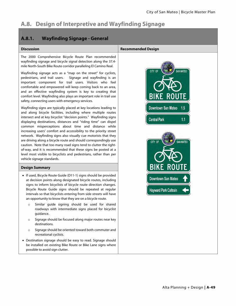
The 2000 Comprehensive Bicycle Route Plan recommended wayfinding signage and bicycle signal detection along the 37.4-mile North-South Bike Route corridor paralleling El Camino Real.
Wayfinding signage acts as a “map on the street” for cyclists, pedestrians, and trail users. Signage and wayfinding is an important component for trail users. Visitors who feel comfortable and empowered will keep coming back to an area, and an effective wayfinding system is key to creating that comfort level. Wayfinding also plays an important role in trail use safety, connecting users with emergency services.
Wayfinding signs are typically placed at key locations leading to and along bicycle facilities, including where multiple routes intersect and at key bicyclist “decision points.” Wayfinding signs displaying destinations, distances and “riding time” can dispel common misperceptions about time and distance while increasing users’ comfort and accessibility to the priority street network. Wayfinding signs also visually cue motorists that they are driving along a bicycle route and should correspondingly use caution. Note that too many road signs tend to clutter the right-of-way, and it is recommended that these signs be posted at a level most visible to bicyclists and pedestrians, rather than per vehicle signage standards.
Design Summary
If used, Bicycle Route Guide (D11-1) signs should be provided at decision points along designated bicycle routes, including signs to inform bicyclists of bicycle route direction changes. Bicycle Route Guide signs should be repeated at regular intervals so that bicyclists entering from side streets will have an opportunity to know that they are on a bicycle route.
o Similar guide signing should be used for shared roadways with intermediate signs placed for bicyclist guidance.
o Signage should be focused along major routes near key destinations.
o Signage should be oriented toward both commuter and recreational cyclists.
Destination signage should be easy to read. Signage should be installed on existing Bike Route or Bike Lane signs where possible to avoid sign clutter.

Appendix A | Design Guidelines
A-50 | Alta Planning + Design
Design Example Guidance
City of Berkeley, CA Wayfinding Sign
Caltrans Highway Design Manual (Chapter 1000)
MUTCD, Section 9B.20
MUTCD – California Supplement, Section 9B.19 through 21
AASHTO Guide for the Development of Bicycle Facilities
Cost
Sign, regulatory: $150 - $250 per sign

City of San Mateo | Bicycle Master Plan
Alta Planning + Design | A-51
A.9. Bicycle Parking
A.9.1. Bicycle Rack Design
Design Summary City Standard Design
Bicycle racks should be a design that is intuitive and easy to use.
A standard inverted-U style rack shall be the standard for the City of San Mateo.
Bicycle racks should be securely anchored to a surface or structure.
The rack element (part of the rack that supports the bicycle) should keep the bicycle upright by supporting the frame in two places without the bicycle frame touching the rack. The rack should allow one or both wheels to be secured.
Avoid use of multiple-capacity “wave” style racks. Users commonly misunderstand how to correctly park at wave racks, placing their bikes parallel to the rack and limiting capacity to 1 or 2 bikes.
Position racks so there is enough room between parked bicycles. Racks should be situated on 36” minimum centers.
A five-foot aisle for bicycle maneuvering should be provided and maintained beside or between each row of bicycle racks.
Empty racks should not pose a tripping hazard for visually impaired pedestrians. Position racks out of the walkway’s clear zone.
For sidewalks with heavy pedestrian traffic, at least seven feet of unobstructed right-of-way is required.
Racks should be located close to a main building entrance, in a lighted, high-visibility area protected from the elements.
Inverted-U Bicycle Rack
Manufacturers
Palmer: www.bikeparking.com
Park-a-Bike: www.parkabike.com
Dero: www.dero.com
Creative Pipe: www.creativepipe.com
Cycle Safe: www.cyclesafe.com

Appendix A | Design Guidelines
A-52 | Alta Planning + Design
Recommended Design (continued)
Design Example Guidance
Short-term bicycle parking showing recommended clearances (non-local)
Association of Bicycle and Pedestrian Professionals Bicycle Parking Guidelines (2nd edition 2010)
City of Oakland, CA Bicycle Parking Ordinance (2008)
Cost
Bicycle racks: $150-$200 each

City of San Mateo | Bicycle Master Plan
Alta Planning + Design | A-53
A.9.2. Bicycle Locker Design
Design Summary Recommended Design
Bicycle lockers should be a design that is intuitive and easy to use.
Bicycle lockers should be electronically accessed. Electronic bicycle locker models from elocker and CycleSafe
allow users to access lockers with a SmartCard (linked to a credit card) or mobile phone, respectively.
Bicycle lockers should be securely anchored to a surface or structure.
Bicycle lockers should be constructed to provide protection from theft, vandalism and weather.
A five-foot aisle for bicycle maneuvering should be provided and maintained beside or between each row of bicycle lockers.
Lockers should be located close to a main building entrance, in a lighted, high-visibility area protected from the elements. Long-term parking should always be protected from the weather.
Manufacturers
Palmer: www.bikeparking.com (includes keyed lockers with optional conversion to use a “u-lock” to lock the locker)
Park-a-Bike: www.parkabike.com
Dero: www.dero.com
Creative Pipe: www.creativepipe.com
Cycle Safe: www.cyclesafe.com
Elock Technologies / BikeLink: www.bikelink.org
Operators
BikeLink: www.bikelink.org
CycleSafe SmartTek: www.cyclesafe.com
Guidance
Association of Bicycle and Pedestrian Professionals Bicycle Parking Guidelines (2nd edition, 2010)
City of Oakland, CA Bicycle Parking Ordinance (2008)
Cost
Bicycle lockers: $1,350-$2,000 each

Appendix A | Design Guidelines
A-54 | Alta Planning + Design
A.10. Maintenance Standards Like all roadways, bicycle and pedestrian facilities require regular maintenance. This includes sweeping, re-striping,
maintaining a smooth roadway, ensuring that the gutter-to-pavement transition remains relatively flat, and installing
bicycle-friendly drainage grates. Shared use paths also require regular plant trimming. The following
recommendations are provided as a maintenance guideline for the City of San Mateo to consider as it augments and
enhances its maintenance capabilities.
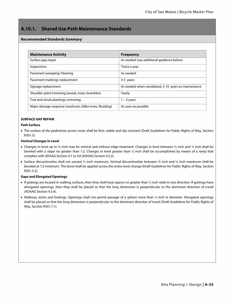
City of San Mateo | Bicycle Master Plan
Alta Planning + Design | A-55
A.10.1. Shared Use Path Maintenance Standards
Recommended Standards Summary
Maintenance Activity Frequency Surface gap repair As needed (see additional guidance below)
Inspections Twice a year
Pavement sweeping/ blowing As needed
Pavement markings replacement 3-5 years
Signage replacement As needed when vandalized, 5-10 years as maintenance
Shoulder plant trimming (weeds, trees, brambles) Yearly
Tree and shrub plantings, trimming 1 – 3 years
Major damage response (washouts, fallen trees, flooding) As soon as possible
SURFACE GAP REPAIR
Path Surface
The surface of the pedestrian access route shall be firm, stable and slip resistant (Draft Guidelines for Public Rights of Way, Section R301.5).
Vertical Changes in Level
Changes in level up to ¼ inch may be vertical and without edge treatment. Changes in level between ¼ inch and ½ inch shall be beveled with a slope no greater than 1:2. Changes in level greater than ½ inch shall be accomplished by means of a ramp that complies with ADAAG Section 4.7 or 4.8 (ADAAG Section 4.5.2).
Surface discontinuities shall not exceed ½ inch maximum. Vertical discontinuities between ¼ inch and ½ inch maximum shall be beveled at 1:2 minimum. The bevel shall be applied across the entire level change (Draft Guidelines for Public Rights of Way, Section R301.5.2).
Gaps and Elongated Openings
If gratings are located in walking surfaces, then they shall have spaces no greater than ½ inch wide in one direction. If gratings have elongated openings, then they shall be placed so that the long dimension is perpendicular to the dominant direction of travel (ADAAG Section 4.5.4).
Walkway Joints and Gratings. Openings shall not permit passage of a sphere more than ½ inch in diameter. Elongated openings shall be placed so that the long dimension is perpendicular to the dominant direction of travel (Draft Guidelines for Public Rights of Way, Section R301.7.1).
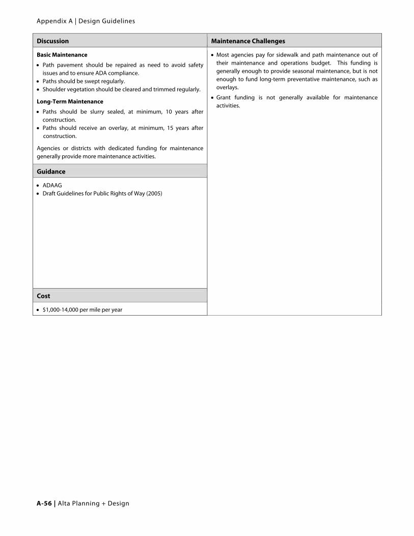
Appendix A | Design Guidelines
A-56 | Alta Planning + Design
Discussion Maintenance Challenges
Basic Maintenance
Path pavement should be repaired as need to avoid safety issues and to ensure ADA compliance.
Paths should be swept regularly. Shoulder vegetation should be cleared and trimmed regularly.
Long-Term Maintenance
Paths should be slurry sealed, at minimum, 10 years after construction.
Paths should receive an overlay, at minimum, 15 years after construction.
Agencies or districts with dedicated funding for maintenance generally provide more maintenance activities.
Most agencies pay for sidewalk and path maintenance out of their maintenance and operations budget. This funding is generally enough to provide seasonal maintenance, but is not enough to fund long-term preventative maintenance, such as overlays.
Grant funding is not generally available for maintenance activities.
Guidance
ADAAG Draft Guidelines for Public Rights of Way (2005)
Cost
$1,000-14,000 per mile per year

City of San Mateo | Bicycle Master Plan
Alta Planning + Design | A-57
A.10.2. On-Street Facility Maintenance Standards
Recommended Standards Summary
Maintenance Activity Frequency Inspections Seasonal – at beginning and end of Summer
Pavement sweeping/blowing As needed, weekly in Fall
Pavement sealing, potholes 5 - 15 years
Culvert and drainage grate inspection Before Winter and after major storms
Pavement markings replacement (including crosswalks) 1 – 3 years
Signage replacement 1 – 3 years
Shoulder plant trimming (weeds, trees, brambles) Twice a year; middle of growing season and early Fall
Tree and shrub plantings, trimming 1 – 3 years
Major damage response (washouts, fallen trees, flooding) As soon as possible
NOTE: Caltrans recommends tolerance of surface discontinuities no more than ½ inch wide when parallel to the direction of travel on bike lanes (Class II) and bike routes (Class III).
Discussion
Basic Maintenance
Bicyclists often avoid shoulders and bike lanes filled with sanding materials, gravel, broken glass and other debris; they will ride in the roadway to avoid these hazards, causing conflicts with motorists. A regularly scheduled inspection and maintenance program helps ensure that roadway debris is regularly picked up or swept. Roadways should also be swept after automobile collisions.
Long-Term Maintenance
Roadway surface is a critical issue for bicyclists’ quality. Bicycles are much more sensitive to subtle changes in roadway surface than are motor vehicles. Examine pavement quality and transitions during every roadway project for new construction, maintenance activities, and construction project activities that occur in streets.
Cost
$1,000-$2,000 per mile per year

Appendix A | Design Guidelines
A-58 | Alta Planning + Design
This page intentionally left blank.