an introduction to eeg artifacts -...
TRANSCRIPT
An introduction to EEG artifactsMat-2.4108 Independent research projects in applied mathematics
Antti Savelainen 63220J
20 February 2010
1
Contents
Contents 2
1 Introduction 3
2 EEG phenomenology 3
3 Artifacts 8
3.1 External artifacts . . . . . . . . . . . . . . . . . . . . . . . . . 8
3.2 Internal artiacts . . . . . . . . . . . . . . . . . . . . . . . . . . 10
3.2.1 Movement artifacts . . . . . . . . . . . . . . . . . . . . 10
3.2.2 Oculogenic potentials . . . . . . . . . . . . . . . . . . . 12
3.2.3 Myogenic potentials . . . . . . . . . . . . . . . . . . . . 12
3.2.4 Potentials related to cardiac activity . . . . . . . . . . 13
3.2.5 Other sources of internal artifacts . . . . . . . . . . . . 15
4 Artifact detection 15
4.1 Removal of rhytmical artifacts . . . . . . . . . . . . . . . . . . 15
4.2 Removal of eye blink artifacts . . . . . . . . . . . . . . . . . . 16
4.3 AR-modeling . . . . . . . . . . . . . . . . . . . . . . . . . . . 17
5 Characteristic properties of EEG in intensive care unit 18
6 Conclusions 19
2
1 Introduction
The aim of this work is to present the most common artifacts related toEEG, i.e. electroencephalography measurement. An artifact is considered adisturbance in a measured brain signal not originating from the brains. Thedifferent sources of artifacts are classified to external and internal categories.Some typical artifacts are identified and illustrated from a recorded signal.
Some EEG signal processing methods for detection of artifacts are presentedand experimented in practice. Moreover, the significance of identification isemphasized with an example from ICU, i.e. intensive care unit. It will beshown that an epileptic seizure and an artifact can easily be mixed with eachother.
2 EEG phenomenology
The EEG is the brain electrical activity measured by putting electrodes onthe scalp. The joint activity of millions of cortical neurons, at the depth ofseveral millimeters, produces an electrical field which is sufficiently strong tobe measured from the human scalp. [1] Typically, the amplitude of an EEGsignal is approximately from 40 to 100 µV with the frequency range from 0to 100 Hz. [2]
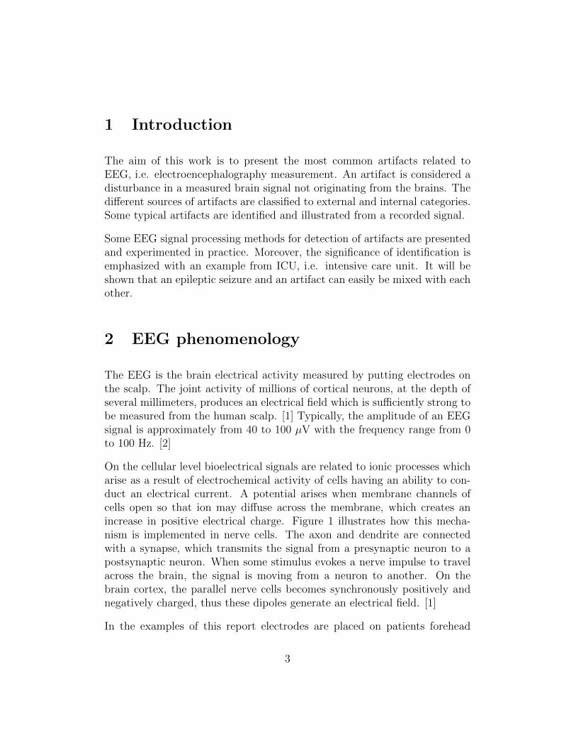
On the cellular level bioelectrical signals are related to ionic processes whicharise as a result of electrochemical activity of cells having an ability to con-duct an electrical current. A potential arises when membrane channels ofcells open so that ion may diffuse across the membrane, which creates anincrease in positive electrical charge. Figure 1 illustrates how this mecha-nism is implemented in nerve cells. The axon and dendrite are connectedwith a synapse, which transmits the signal from a presynaptic neuron to apostsynaptic neuron. When some stimulus evokes a nerve impulse to travelacross the brain, the signal is moving from a neuron to another. On thebrain cortex, the parallel nerve cells becomes synchronously positively andnegatively charged, thus these dipoles generate an electrical field. [1]
In the examples of this report electrodes are placed on patients forehead
3
Figure 1: Two neurons transmitting a signal
shown in Figure 2. The EEG signal is represented as a graph of voltageversus time. The measured voltage is obtained as the potential differencebetween two electrode sites placed on the scalp.
The potential difference is a measured potential respect to the reference point(noted by R). The measured signal is amplified and the actual signals are lf,i.e. left frontal, rf, i.e. right frontal, lt, i.e. low temporal and rt, i.e. righttemporal are then produced by subtracting the measured potential differencesrelated to the reference point R, which becomes to a simple form
2-R - ( 3 - R ) = 2-3 = lf(1)
The recorded signals and their names are shown in Table 1. This electrodeinstallation is a so called sub-hairline montage. It is easy to use, because itenables the use of sticker electrodes, which do not require skin preparation,
4
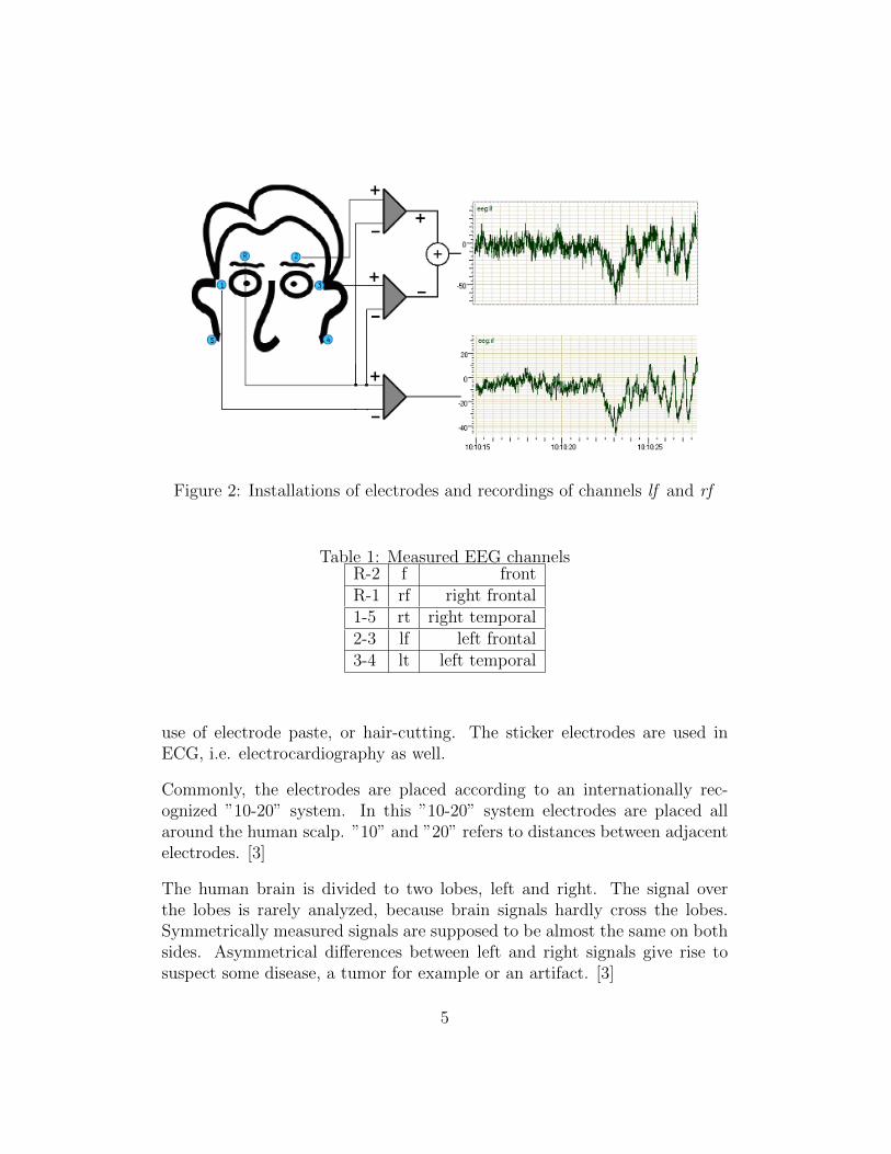
Figure 2: Installations of electrodes and recordings of channels lf and rf
Table 1: Measured EEG channelsR-2 f frontR-1 rf right frontal1-5 rt right temporal2-3 lf left frontal3-4 lt left temporal
use of electrode paste, or hair-cutting. The sticker electrodes are used inECG, i.e. electrocardiography as well.
Commonly, the electrodes are placed according to an internationally rec-ognized ”10-20” system. In this ”10-20” system electrodes are placed allaround the human scalp. ”10” and ”20” refers to distances between adjacentelectrodes. [3]
The human brain is divided to two lobes, left and right. The signal overthe lobes is rarely analyzed, because brain signals hardly cross the lobes.Symmetrically measured signals are supposed to be almost the same on bothsides. Asymmetrical differences between left and right signals give rise tosuspect some disease, a tumor for example or an artifact. [3]
5
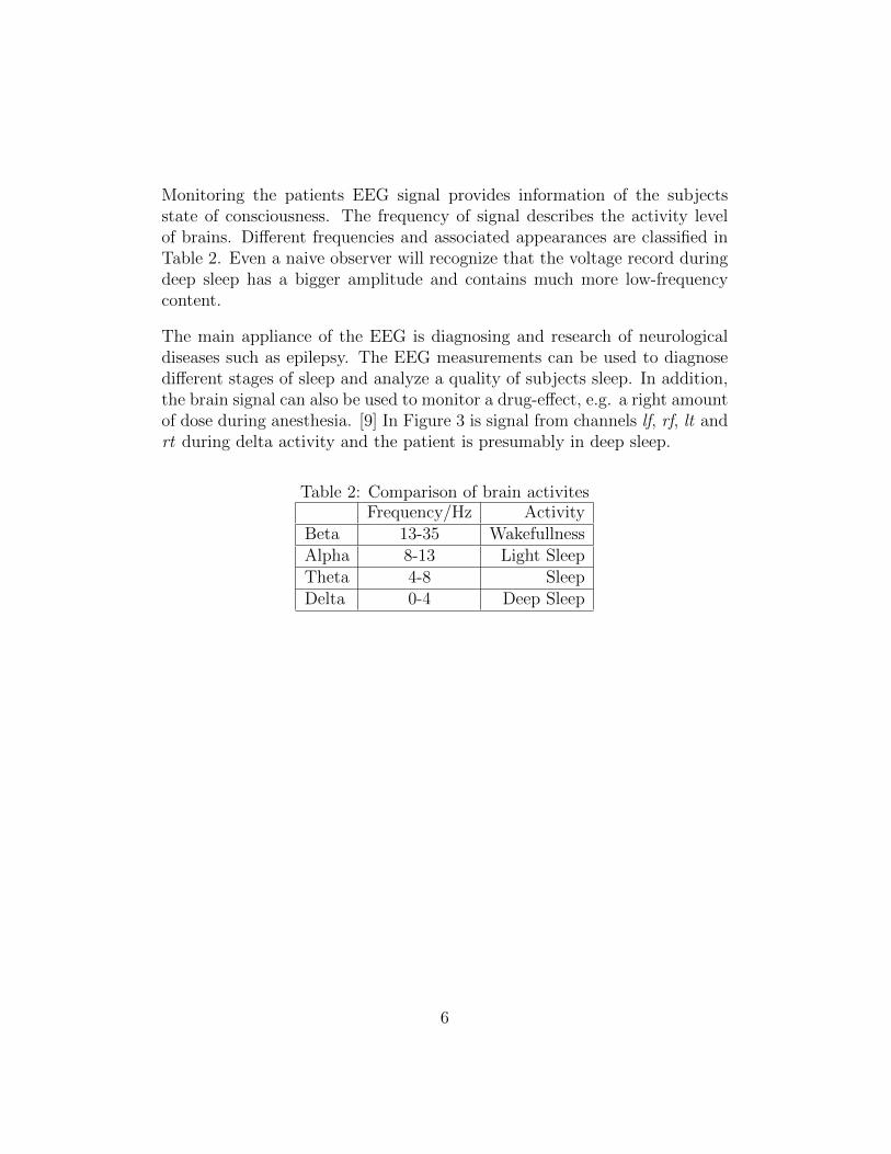
Monitoring the patients EEG signal provides information of the subjectsstate of consciousness. The frequency of signal describes the activity levelof brains. Different frequencies and associated appearances are classified inTable 2. Even a naive observer will recognize that the voltage record duringdeep sleep has a bigger amplitude and contains much more low-frequencycontent.
The main appliance of the EEG is diagnosing and research of neurologicaldiseases such as epilepsy. The EEG measurements can be used to diagnosedifferent stages of sleep and analyze a quality of subjects sleep. In addition,the brain signal can also be used to monitor a drug-effect, e.g. a right amountof dose during anesthesia. [9] In Figure 3 is signal from channels lf, rf, lt andrt during delta activity and the patient is presumably in deep sleep.
Table 2: Comparison of brain activitesFrequency/Hz Activity
Beta 13-35 WakefullnessAlpha 8-13 Light SleepTheta 4-8 SleepDelta 0-4 Deep Sleep
6
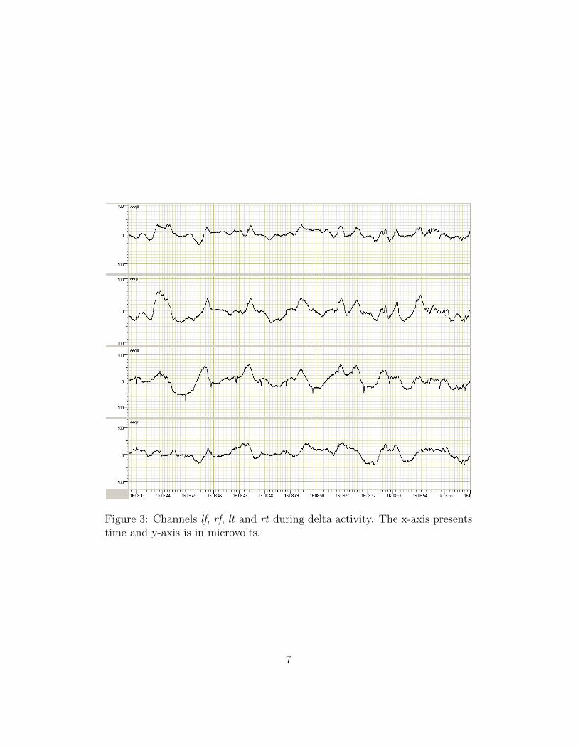
Figure 3: Channels lf, rf, lt and rt during delta activity. The x-axis presentstime and y-axis is in microvolts.
7
3 Artifacts
The EEG signals contain artifacts in practice. Artifacts are considered un-wanted signals or interference in a signal. Different types of artifacts can bedivided to external and internal artifacts. External artifacts are caused byouter actions and internal artifacts are associated with the actions made bysubject itself. The classification of artifacts is summarized in Table 3.
3.1 External artifacts
External artifacts result often from unsatisfactory technology. EEG measure-ment technology consists of apparatus and connections. The mains frequencymay cause an artifact by appearing as a 50 Hz component in EEG signal.This same phenomenon may appear as well in recordings where a battery isused as a power supply. The surrounding walls and electric cables producea constant electric field. In addition, external electronic devices may faultmeasured signal by creating electric and magnetic fields. [3]
The revolution that has taken place in the design and construction of EEGapparatus has reduced the incidence of machine faults. On the other hand,the possibility of machine faults have risen along with machines greater com-plexity. Purely mechanical machine faults normally appear as a total loss ofsignal or somehow easily detectable feature. More significant machine faultsconcern software development and a proper algorithm design. [3]
It is possible, that electrodes simply detaches from patients forehead whichvanishes the signal shown in Figure 4. As a result, first the potential dif-ference rises to infinity and thereafter there is no longer potential differencebetween electrodes and the signal strives to zero. In Figure 4, there is alsonoteworthy noise in channels lf and rt that is presumably connected to re-moval of electrodes. The signal of lt channel obviously consists in additionto EEG signal features of ECG activity. There is also ECG signal illustratedin Figure 4.
Moreover, sometimes electrodes are attached on the hair area or the contactis not ensured by moisturizing patients skin. It is also possible that theelectrodes are pressed or pushed. The two discontinuous spikes in channel rf
8
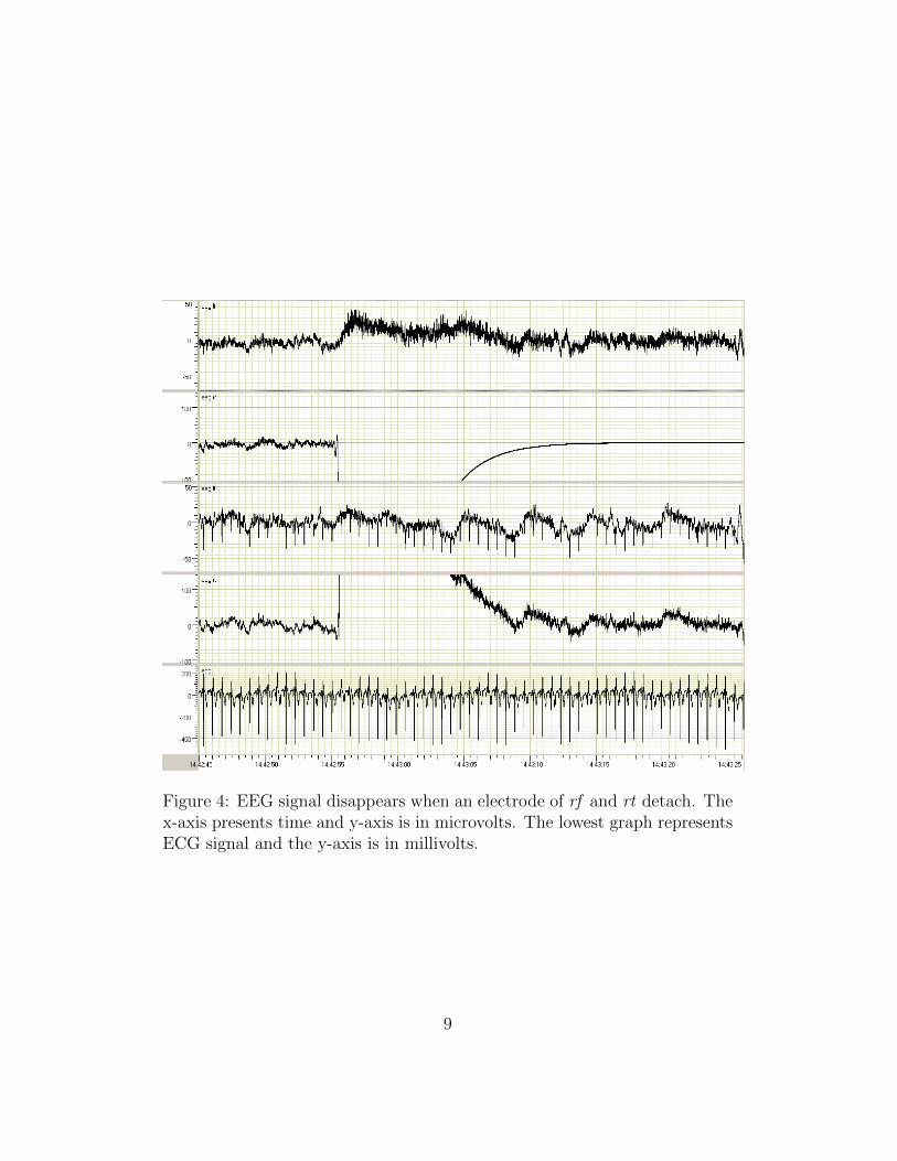
Figure 4: EEG signal disappears when an electrode of rf and rt detach. Thex-axis presents time and y-axis is in microvolts. The lowest graph representsECG signal and the y-axis is in millivolts.
9
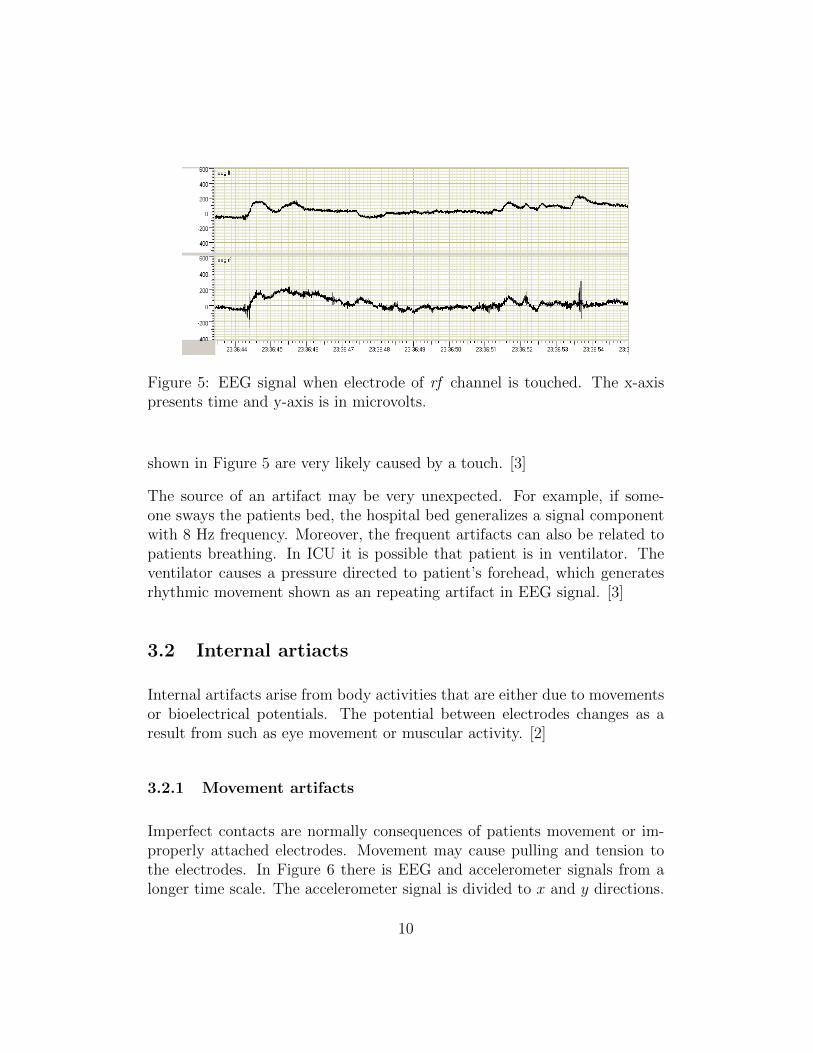
Figure 5: EEG signal when electrode of rf channel is touched. The x-axispresents time and y-axis is in microvolts.
shown in Figure 5 are very likely caused by a touch. [3]
The source of an artifact may be very unexpected. For example, if some-one sways the patients bed, the hospital bed generalizes a signal componentwith 8 Hz frequency. Moreover, the frequent artifacts can also be related topatients breathing. In ICU it is possible that patient is in ventilator. Theventilator causes a pressure directed to patient’s forehead, which generatesrhythmic movement shown as an repeating artifact in EEG signal. [3]
3.2 Internal artiacts
Internal artifacts arise from body activities that are either due to movementsor bioelectrical potentials. The potential between electrodes changes as aresult from such as eye movement or muscular activity. [2]
3.2.1 Movement artifacts
Imperfect contacts are normally consequences of patients movement or im-properly attached electrodes. Movement may cause pulling and tension tothe electrodes. In Figure 6 there is EEG and accelerometer signals from alonger time scale. The accelerometer signal is divided to x and y directions.
10
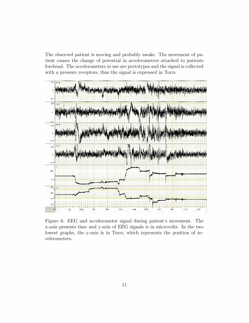
The observed patient is moving and probably awake. The movement of pa-tient causes the change of potential in accelerometers attached to patientsforehead. The accelerometers in use are prototypes and the signal is collectedwith a pressure receptors, thus the signal is expressed in Torrs.
Figure 6: EEG and accelerometer signal during patient’s movement. Thex-axis presents time and y-axis of EEG signals is in microvolts. In the twolowest graphs, the y-axis is in Torrs, which represents the position of ac-celerometers.
11
3.2.2 Oculogenic potentials
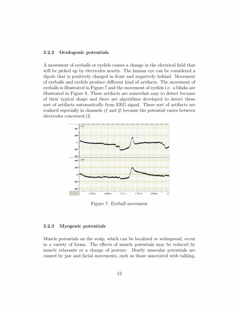
A movement of eyeballs or eyelids causes a change in the electrical field thatwill be picked up by electrodes nearby. The human eye can be considered adipole that is positively charged in front and negatively behind. Movementof eyeballs and eyelids produce different kind of artifacts. The movement ofeyeballs is illustrated in Figure 7 and the movement of eyelids i.e. a blinks areillustrated in Figure 8. These artifacts are somewhat easy to detect becauseof their typical shape and there are algorithms developed to detect thesesort of artifacts automatically from EEG signal. These sort of artifacts arerealized especially in channels rf and lf, because the potential varies betweenelectrodes concerned.[4]
Figure 7: Eyeball movement
3.2.3 Myogenic potentials
Muscle potentials on the scalp, which can be localized or widespread, occurin a variety of forms. The effects of muscle potentials may be reduced bymuscle relaxants or a change of posture. Mostly muscular potentials arecaused by jaw and facial movements, such as those associated with talking,
12
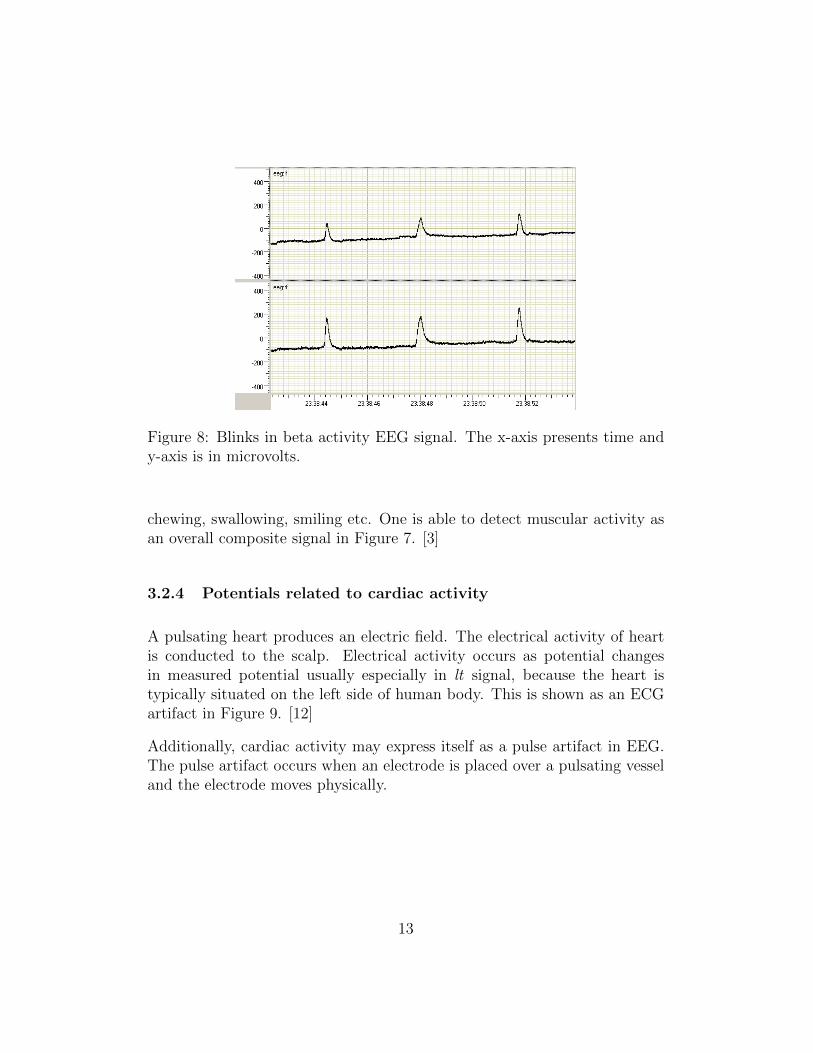
Figure 8: Blinks in beta activity EEG signal. The x-axis presents time andy-axis is in microvolts.
chewing, swallowing, smiling etc. One is able to detect muscular activity asan overall composite signal in Figure 7. [3]
3.2.4 Potentials related to cardiac activity
A pulsating heart produces an electric field. The electrical activity of heartis conducted to the scalp. Electrical activity occurs as potential changesin measured potential usually especially in lt signal, because the heart istypically situated on the left side of human body. This is shown as an ECGartifact in Figure 9. [12]
Additionally, cardiac activity may express itself as a pulse artifact in EEG.The pulse artifact occurs when an electrode is placed over a pulsating vesseland the electrode moves physically.
13
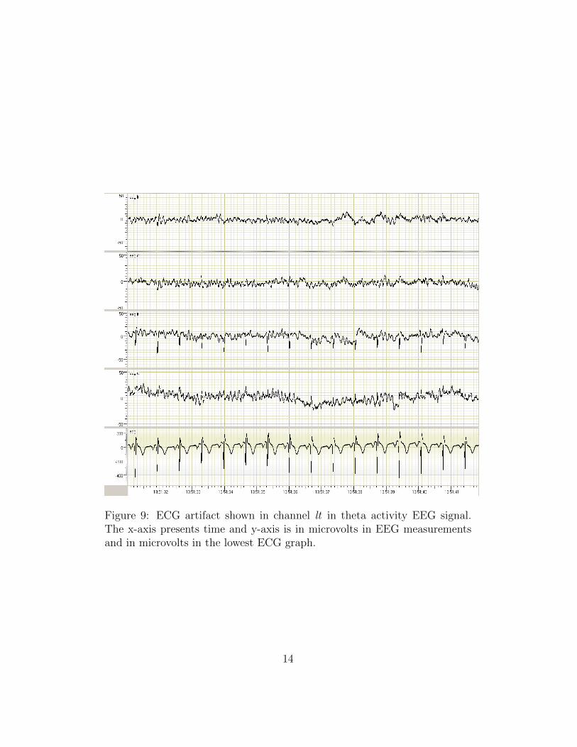
Figure 9: ECG artifact shown in channel lt in theta activity EEG signal.The x-axis presents time and y-axis is in microvolts in EEG measurementsand in microvolts in the lowest ECG graph.
14
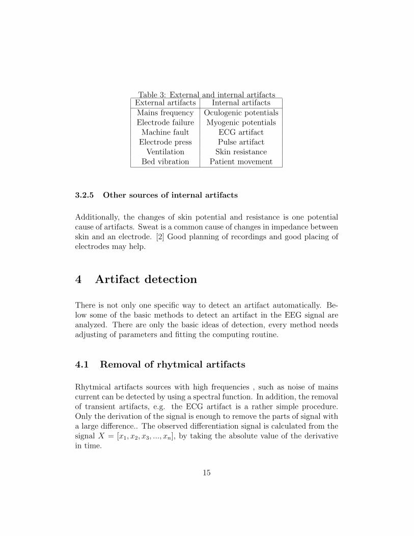
Table 3: External and internal artifactsExternal artifacts Internal artifactsMains frequency Oculogenic potentialsElectrode failure Myogenic potentials
Machine fault ECG artifactElectrode press Pulse artifact
Ventilation Skin resistanceBed vibration Patient movement
3.2.5 Other sources of internal artifacts
Additionally, the changes of skin potential and resistance is one potentialcause of artifacts. Sweat is a common cause of changes in impedance betweenskin and an electrode. [2] Good planning of recordings and good placing ofelectrodes may help.
4 Artifact detection
There is not only one specific way to detect an artifact automatically. Be-low some of the basic methods to detect an artifact in the EEG signal areanalyzed. There are only the basic ideas of detection, every method needsadjusting of parameters and fitting the computing routine.
4.1 Removal of rhytmical artifacts
Rhytmical artifacts sources with high frequencies , such as noise of mainscurrent can be detected by using a spectral function. In addition, the removalof transient artifacts, e.g. the ECG artifact is a rather simple procedure.Only the derivation of the signal is enough to remove the parts of signal witha large difference.. The observed differentiation signal is calculated from thesignal X = [x1, x2, x3, ..., xn], by taking the absolute value of the derivativein time.
15
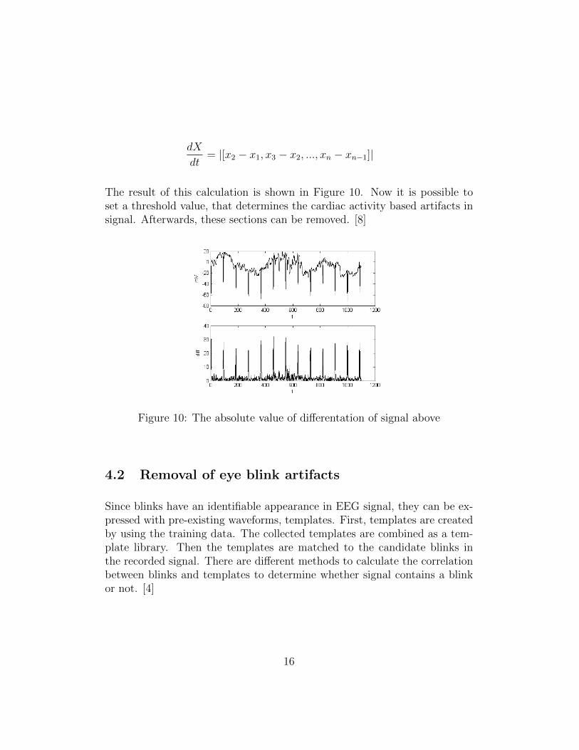
dX
dt= |[x2 − x1, x3 − x2, ..., xn − xn−1]|
The result of this calculation is shown in Figure 10. Now it is possible toset a threshold value, that determines the cardiac activity based artifacts insignal. Afterwards, these sections can be removed. [8]
Figure 10: The absolute value of differentation of signal above
4.2 Removal of eye blink artifacts
Since blinks have an identifiable appearance in EEG signal, they can be ex-pressed with pre-existing waveforms, templates. First, templates are createdby using the training data. The collected templates are combined as a tem-plate library. Then the templates are matched to the candidate blinks inthe recorded signal. There are different methods to calculate the correlationbetween blinks and templates to determine whether signal contains a blinkor not. [4]
16
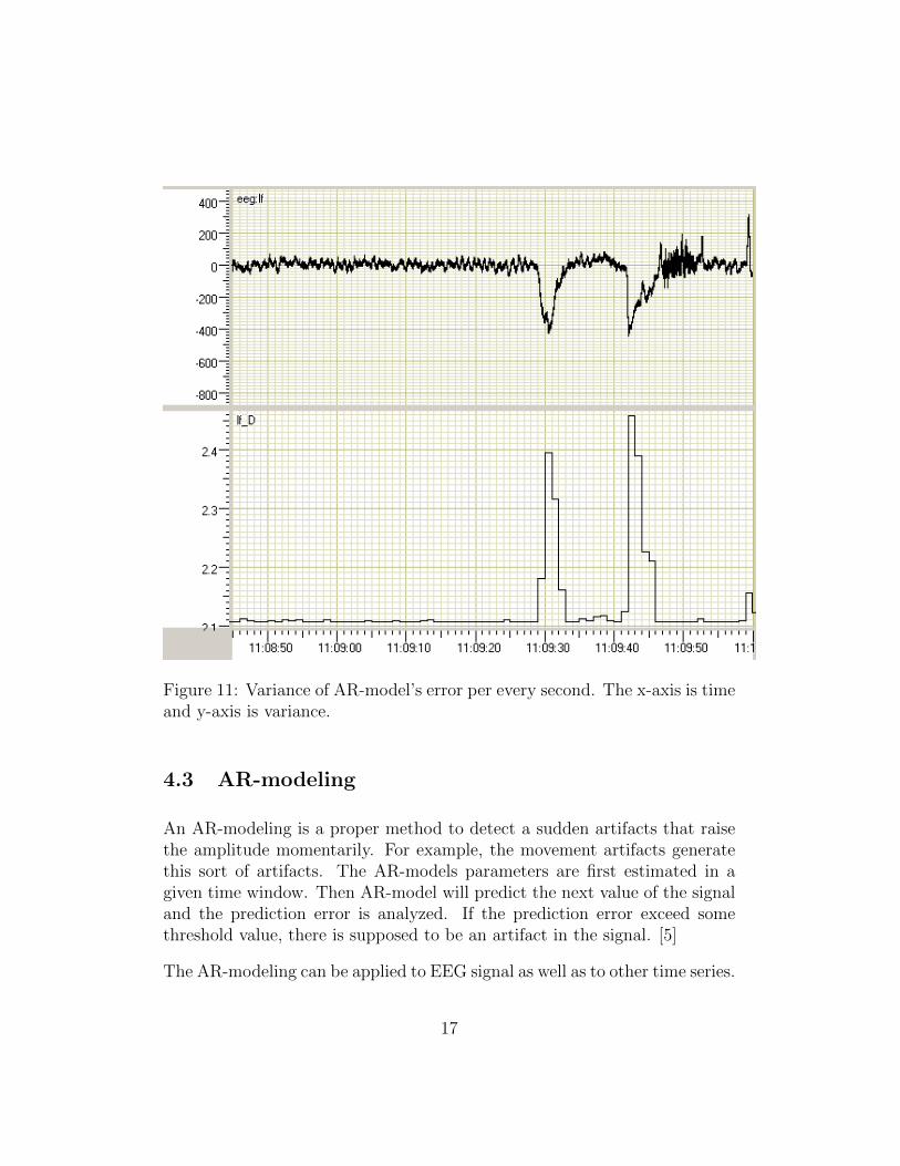
Figure 11: Variance of AR-model’s error per every second. The x-axis is timeand y-axis is variance.
4.3 AR-modeling
An AR-modeling is a proper method to detect a sudden artifacts that raisethe amplitude momentarily. For example, the movement artifacts generatethis sort of artifacts. The AR-models parameters are first estimated in agiven time window. Then AR-model will predict the next value of the signaland the prediction error is analyzed. If the prediction error exceed somethreshold value, there is supposed to be an artifact in the signal. [5]
The AR-modeling can be applied to EEG signal as well as to other time series.
17
In this case, the length of a time window, where the AR-model’s parametersare estimated may be set to 2 seconds and the order of AR-model to 10. Thealgorithm in question produces the variance of the AR-model error per everysecond. It is essential, that the AR-model is estimated within a window,that consists signal without artifacts. Consequently, the algorithm detectsartifacts more efficiently. This sort of model produces consequently positiveresult that varies according to unexpected components of the EEG signal.The produced model is the basic AR-model
xt =10∑i=1
θi xt−i + εt
where θ1, . . . , θp are the parameters of the model and εt is white noise [10].
The parameters θi may be estimated in the time window of 2 seconds in thebeginning of the processed signal. Next, every value of signal are estimatedand the variance of the error et is calculated per every second, for instance.[6] AR-modeling with the above-mentioned parameters and computing yieldsa variance which is illustrated in Figure 11.
5 Characteristic properties of EEG in inten-
sive care unit
It is important to note, that critically ill patients in the intensive care unithas a higher risk of seizures and status epilepticus, i.e. a condition in whichthe brain is in a state of persistent seizure. Nonconvulsive seizures (NCSz),i.e. an epileptic seizure without observable cramps and nonconvulsive statusepilepticus (NCSE) can be detected only with the EEG monitoring. Theyare increasingly recognized as common occurrences in the ICU, where 8 - 48percent of comatose patients may have NCSz or NCSE. Repetitive seizureslead to permanent brain injuries, such as cell loss and increase the risk fordeveloping epilepsy. [7]
For example, there is an extremely intense seizure i.e. a periodic epileptiform
18
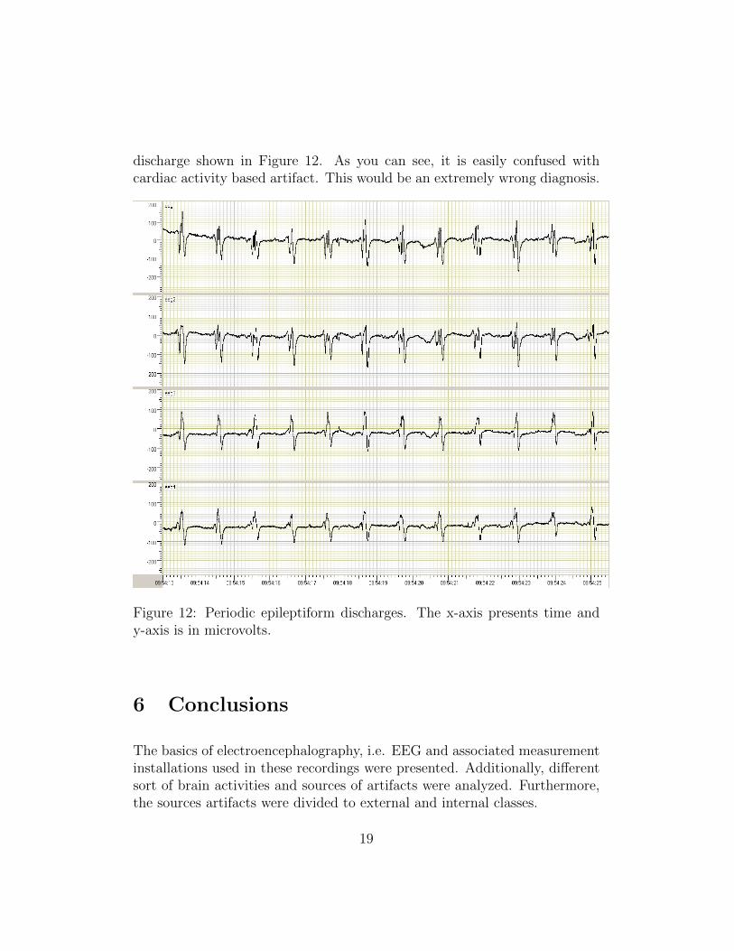
discharge shown in Figure 12. As you can see, it is easily confused withcardiac activity based artifact. This would be an extremely wrong diagnosis.
Figure 12: Periodic epileptiform discharges. The x-axis presents time andy-axis is in microvolts.
6 Conclusions
The basics of electroencephalography, i.e. EEG and associated measurementinstallations used in these recordings were presented. Additionally, differentsort of brain activities and sources of artifacts were analyzed. Furthermore,the sources artifacts were divided to external and internal classes.
19
Artifacts are manifested differently in EEG signal and there is not such aone single method to deal with. It is always depended on the certain sit-uation, how to concern artifacts wether it is needed or not. Although, themost common methods to detect artifacts were presented, that are based onbasic mathematical functions, such as derivation and Fourier transform andestimation theory. After the artifacts have been detected, the removal ofartifactual periods from the signal is trivial: the detected part of the signalis simply deleted. The removal criterions such as threshold values and lengthof deleted period can be determined by means of ROC analysis. [11]
It was pointed out that it is important to be aware of artifacts within EEGrecording in intensive care unit. Thus one doesn’t draw wrong conclusions ofrecordings. The nonconvulsive epileptic seizures were analyzed to show thetroublesome essence of artifacts. Seizures and artifacts are easily mixed upwhich may cause serious brain injuries. This gives rise to further researchto firstly removal of artifacts and secondly automatic detection of seizures.Consequently the number of serious brain injuries could be decreased.
20
References
[1] Sornmo L, Laguna P. Bioelectrical signal processing in cardiac andneurological applications, Elsevier Academic Press, 2005. ISBN: 0-12-437552-9
[2] Fisch, BJ. EEG PRIMER Basic principles of digital and analog EEG,3rd edition, Elsevier Academic Press, 1999. ISBN: 0-444-82147-3
[3] Binnie C, Cooper R, Mauguire F, Osselton J, Prior P, Tedman B. Clini-cal Neurophysiology, Elsevier Academic Press, 2003. ISBN: 0-444-51257-8
[4] Polkko J. A Method for Detecting Eye Blinks from Single-ChannelBiopotential Signal in the Intensive Care Unit Master’s Thesis, 2007.
[5] Pardey J, Roberts S, Tarassenko L. A review of parametric modellingtechniques for EEG analysis Med. Eng. Phys., 1996, Vol. 18, 2-11, Jan-uary
[6] Lopes Da Silva F.H., Van Hulten K, Lommen JG, Storm Van LeeuwenW, Van Veelen CWM, Vliegenthart W. Automatic Detection and lo-calization of epileptic foci, Electroencephalography and Clinical Neuro-physiology, 1977, 43:1-13
[7] Friedman D, Claassen J, Hirsch LJ. Continuous ElectroencephalogramMonitoring in the Intensive Care Unit Anesthesia Analgesia, Vol. 109,No. 2, August 2009
[8] Ifeachor EC, Jervis BW. Digital Signal Processing Addison-Wesley Pub-lishers Ltd., 1993. ISBN: 0-201-54413-X
[9] Sarkela M. Monitoring Depth of Anesthesia with Electroencephalogram:Methods and Performance Evaluation TKK Dissertations, 2008. ISBN:978-951-22-9288-2
[10] Box GE, Ljung G Time Series Analysis: Forecast and Control Holden-Day Inc, 1970.
[11] Fawcett T, An introduction to ROC analysis Pattern Recognition Let-ters 27, 2006, 861-874
21

[12] Dirlich G, Dietl T, Vogl L, Strian F Topography and morphology of heartaction-related EEG potentials Electroencephalography and Clinical Neu-rophysiology, 1998, 108:299-305
22