an internship report on power distribution systems
TRANSCRIPT

AN INTERNSHIP REPORT ON
POWER DISTRIBUTION SYSTEMS
A Project and Thesis submitted in partial fulfilment of the requirements for the Award of Degree of
Bachelor of Science in Electrical and Electronic Engineering
Submitted by
Iffatara Tarafdar ID:132-33-1460
Md.Tipu Sultan ID:132-33-1529
Supervised by Professor Dr. M. Shamsul Alam
Professor and Dean Faculty of Engineering
DEPARTMENT OF ELECTRICAL AND ELECTRONIC ENGINEERING FACULTY OF ENGINEERING
DAFFODIL INTERNATIONAL UNIVERSITY
NOVEMBER-2018

ii ©Daffodil International University
CONCERN LETTER

iii ©Daffodil International University
CONCERN LETTER

iv ©Daffodil International University

v ©Daffodil International University
DEDICATED TO
OUR PARENTS

vi ©Daffodil International University
ACKNOWLEDGEMENTS
All praises go to Allah, the almighty, for the successful completion of this internship and
fulfillment of ours dream into reality. However, thanks and gratitude are also due to the following
persons for their continuous support in completing this internship and in preparing this report.
First of all, we would like to express our sincere appreciation, heartfelt gratitude and cordial
thanks to our internship supervisor, Professor Dr. M. Shamsul Alam, Dean, Faculty of Engineering
(FE) of Department of EEE, Daffodil International University, Bangladesh for his invaluable
instructions, continuous guidance, constructive criticisms and thoughtful advice during pursuing
this internship and preparation of this report.
We also want to convey our thankfulness to Most. Mahzuba Islam, Senior Lecturer of the
Department of EEE for her help, support and constant encouragement. This report can’t be done
without her useful advice and helps. Also thank you very much for giving us opportunity to
choose this internship program.
Special thanks are extended to our fellow classmates of the Department of Electrical and
Electronic Engineering, Daffodil International University, Bangladesh for their helping hand,
continuous support and cooperation during this internship.
Finally, we proudly acknowledges the great sacrifices, good wishes, moral support, fruitful
advice, inspirations and encouragements from our family members, relatives and friends which
help us to finish the internship successfully.
vii ©Daffodil International University
ABSTRACT
Electricity plays a vital role in the socio-economic development and poverty alleviation. It is
considered as the driving force of all development activities. To alleviate poverty in the face of
resource limitations and high population density, Bangladesh requires an economic growth rate of
about 10% p.a. to provide employment to its rapidly growing labor force that cannot be absorbed
by agriculture. In order to achieve this growth rate, availability of a reasonably priced and reliable
source of electricity is a prerequisite.The power sector in Bangladesh faced numerous problems
characterized by lack of supply capacity, frequent power cuts, unacceptable quality of supply,
and poor financial and operational performance of the sector entities. The customer service is not
praiseworthy. There have been a number of reforms in the power sector in Bangladesh since her
independence, but most of these reforms failed to bring desired improvements in the power
sector. The most pressing problem in the power sector has been with the distribution system,
which is characterized by heavy system loss and poor collection performance; however, the
distribution system seldom got the priority in reform initiatives.

viii ©Daffodil International University
TABLE OF CONTENTS
Acknowledgement
vii
Abstract viii
List of Figures xiii
List of Abbreviations List of Tables
xv xvi
Chapter 1 Introduction
1.1 Introduction 1
1.2 History of power sector in Bangladesh 2
1.3 Structure of Power Sector in Bangladesh 4
1.4 Objective 5
1.4.1 Broad Objective 5
1.4.2 Specific Objective 5
1.5 Dhaka Electric Supply Company Limited(DESCO) 5
1.5.1 Vision 5
1.5.2 Mission 5
1.5.3 Corporate Philosophy 5
1.6 Internship 6
1.7 Internship Report Outline 6
Chapter 2 Company Profile
2.1 History of DESCO. 7
2.2 Structure of The DESCO 7
2.3 Start UP to the DESCO 8
2.3.1 1st Phase 8
2.3.2 2nd Phase 8
2.4 Project Financing of DESCO 9
2.5 Organization & Service Area of DESCO 9
2.6 Milestones of DESCO 10
2.7 Operational Zone and Sales & Distribution Division 11
ix ©Daffodil International University
2.8 Name of Zones and S&D Divisions 11
2.9 Substation and Sales & Distribution Division 11
2.9.1 It consists of two functions 11
2.9.1.1 Commercial Operation 11
2.9.1.2 System Operation 12
2.10 Fiscal Year Wise Operational Data 12
2.11 Fiscal Year Wise System Loss Graph 13
Chapter 3 OPERATION OF SUBSTATION
3.1 Operation of Substation 14
3.2 Rupnagar S&D at a Glance 14
3.3 Equipment of Substation 16
3.4 Power Transformer 16
Chapter 4 TRANSFORMER (EQUIPMENTS & OPERATION)
4.1 General Equipment 19
4.2 Operational Equipment 19
4.2.1 Transformer at DESCO 19
4.2.2 Transformer Specification 20
4.2.3 Transformer Component 20
4.2.3.1 Winding 21
4.2.3.2 Main Tank 21
4.2.3.3 Conservator Tank 22
4.2.3.4 Buchholz Relay 22
4.2.3.5 Cooling Equipment 23
4.2.3.6 Winding Temperature and Oil Temperature Indicator 23
4.2.3.7 On Load Tap Changer 24
4.2.3.8 Transformer Oil 24
4.2.3.9 Breathing System 24
4.2.4 Losses in Transformer 25
4.2.5 Protection Systems for transformer 25
4.2.6 Auxiliary Transformers 26
4.2.7 Circuit Breaker 26

x ©Daffodil International University
4.2.7.1 SF6 Ga s Circuit breaker 26
4.2.7.2 Vacum Circuit Breakers 27
4.2.8 Potential Transformers 27
4.2.9 Current Transformers 28
4.2.10 Lightin g Arresters 29
4.2.11 Isolator s 30
4.2.12 Bus Ba rs and Bus Coupler 30
4.2.13 Battery and Battery Charger 31 Chapter 5 SUBSTATION MA INTENANCE & PROTECTION
5.1 Maintenance and Inspection of Substation 33
5.2 Transformer Maintenance 34
5.3 Transformer Fault Detection and Repairing 36
5.3.1 Transformer Coil Burn 36
5.3.2 Drop off Fuse 37
5.3.3 Low Dielectric Strength 38
5.4 Power Factor Monitoring & Upgrading 38
5.4.1 Effect of Low Power Factor 38
5.5 Control Room Activity 38
5.6 Incoming Panels or Lines 39
5.6.1 Relay Protection on 33KV Incoming Line 40
5.6.2 Earth Isolator 40
5.7 The 33 KV Transformer Control Panels 41
5.8 Outgoing Feeders 43
Chapter 6 NUMERICAL DATA ANALYSIS(SCADA)
6.1 Introduction 44
6.2 Monthly Energy Statement 44
6.3 Losses 47
6.3.1 Losses in 11 KV side transformer-4 47
6.3.2 Losses in 11 KV side transformer-5 48

xi ©Daffodil International University
6.4 Electricity Tariff in Bangladesh 49
6.4.1 Tariff Rate 49
6.5 Date of Check: T-4 Transformer & T-5 Transformer 50
6.6 Insulation Resistance Test 51
6.7 11 KV Breaker Test Report(Area) 52
6.7.1 General Check
6.7.2 Contract Resistance Test Of 11 KV Breaker 52
6.7.3 Insulation Resistance Test Of 11kv Breaker 53
6.8 Calculation 54
6.8.1 1Losses for 33kV import and 11kv (Transformer4) 56
6.8.2 2Losses for 33kV import and 11kv (Transformer5) 56
6.9 Tariff calculation in Bangladesh 57
6.10 Insulation and Contact resistance calculation 58
6.10.1 Insulation resistance of Transformer T4 & T5 58
6.10.2 Insulation& Contact resistance of Breaker 58
Chapter 7 RESULTS & DISCUSSION
7.1 Introduction 59
7.2 Losses 59
7.3 Tariff calculation 59
7.4 Insulation and Contact resistance calculation of Transformer
& Breaker 60
7.5 Discussion 60
Chapter 8 Conclusions
8.1 Conclusions 61
8.2 Limitations of the work 61
8.3 Future Scopes of the Work 62
References 63

xii ©Daffodil International University
LIST OF FIGURES
Figure Page
Figure 1.1: Power Sector Structure 04
Figure 3.1: Power Transformer(33/11) at Digun Substation 15
Figure 3.2: 33KV incoming source from Uttara Grid, CT, L.A, PT, HT Bushing 15
Figure 3.3 : Power Transformer T1 & T2. 17
Figure 4.1 : 132/33 KV Power transformer (GT1) at Digun Substation . 20
Figure 4.2 : Main tank with primary & secondary winding. 21
Figure 4.3 : Conservator tank at Digun Substation. 22
Figure 4.4 : Action of buchholz relay at Digun substation. 23
Figure 4.5 : Winding temperature and oil temperature indicator. 23
Figure 4.6 : Tap changing mechanism. 24
Figure 4.7 : Transformer breathing system (silica gel) used at DESCO. 25
Figure 4.8 : SF6 gas circuit breaker at Digun grid-substation. 27
Figure4.9 : Potential transformer at Digun grid-substation. 28
Figure 4.10 : Current transformer at Digun grid-substation. 28
Figure 4.11: Lighting Arrester and GT-2 at Digun grid-substation. 29

xiii ©Daffodil International University
Figure 4.12 : Lighting arrester indicator at Digun grid-substation. 30
Figure 4.13 : 132 KV bus bars and bus coupler at Digun grid-substation. 31
Figure 4.14 : Battery back up system of 132/33/11KV Digun grid-substation. 32
Figure 5.1 : Single Line Diagram of Digun Substation. 33
Figure 5.2: Maintenance of Digun 33/11 KV substation. 34
Figure 5.3 : Checking insulation resistance between each winding & ground 35
Figure 5.4:Checking control system & driving mechanism of On Load Tap Changer 36
Figure 5.5 : The 11KV/440KV distribution transformer. 37
Figure 5.6 : Drop out Fuse under Digun Feeder. 37
Figure 5.7 : Control room at substation. 39
Figure 5.8 : The relay protection on 33KV incoming line at Digun substation. 40
Figure 5.9 : The digital relay protection on 33KV transformer panel. 41
Figure 5.10 : The relay protection on 33KV transformer panel at Digun substation. 42

xiv ©Daffodil International University
LIST OF ABBREVIATIONS
CT Current Transformer
PT Potential Transformer
SCADA Supplementary Control And Data Acquisition
GIS Gas Insulated Switchgear
REF Restricted Earth Fault
CB Circuit Breaker
L.A Lightening Arrester
HRC High Rupturing Capacity
CRP Control Relay Panel
MMF Magneto Motive Force
PB Push Bottom
NO Normally Open
NC Normally Close
TC Trip Coil
PR Protective Relay
PE Protective Earth
BERC Bangladesh Energy Regulatory Commission
DESCO Dhaka Electric Supply Company Limited
OMF Overall multiplication factor
AIS Air Insulated Switchgear
PFI Power Factor Improvement

xv ©Daffodil International University
LIST OF TABLES
Table Page
Table2.1: Fiscal year wise operational data. 12
Table2.2: Fiscal year wise system loss. 13
Table 3.1: Digun S&D At a Glance 14
Table 6.1: Monthly Energy Statement 44
Table6.2:losses in 11 KV side transformer-4 47
Table6.3: losses in 11 KV side transformer-5 48
Table6.4: Tariff Rate With Respect To Retail Sales 49
Table6.5: Checking Of Transformer 50
Table 6.6: Test Of Insulation 51
Table 6.7: General Checking Of Breaker 52
Table6.8: Contract Resistance Test 52
Table6.9: Insulation Resistance Test 54

1 ©Daffodil International University
CHAPTER 1 INTRODUCTION
1.1 Introduction
Bangladesh's energy infrastructure is quite small, insufficient and poorlymanaged. The per capita
energy consumption in Bangladesh is considered low by global standards. Noncommercial energy
sources, such as wood fuel, animal waste, and crop residues, are estimated to account for over half
of the country's energy consumption. Bangladesh has small reserves of oil and coal, but very large
natural gas resources. Commercial energy consumption is mostly natural gas (around 66%),
followed by oil, hydropower and coal.
Electricity is the major source of power for most of the country's economic activities. Bangladesh's
total installed electricity generation capacity (including captive power) was 15,351 MW as of
January 2017. As of 2014, only 62% of the population had access to electricity with a per capita
availability of 321 kWh per annum. Problems in the Bangladesh's electric power sector include
corruption in administration, high system losses, delays in completion of new plants, low plant
efficiency, erratic power supply, electricity theft, blackouts, and shortages of funds for power plant
maintenance. Overall, the country's generation plants have been unable to meet system demand
over the past decade.
On 2 November 2014, electricity was restored after a day-long nationwide blackout. A
transmission line from India had failed, which "led to a cascade of failures throughout the national
power grid," and criticism of "old grid infrastructure and poor management." However, in a recent
root-cause analysis report the investing team has clarified that fault was actually due to Lack in
electricity management & poor Transmission & Distribution health infrastructure that caused the
blackout.
2 ©Daffodil International University
1.2 History of Power Sector in Bangladesh
In 1957, the government of East Pakistan took over all private power generation houses and
distribution lines and established Power Development Board (PDB) in 1959 as an associate of the
East Pakistan Water and Power Development Authority (EWPDA). It became an independent
body in 1972 and it’s headquarter was in Dhaka. Its responsibility was to control power plant s
and distribution network throughout Bangladesh.
At first BPDB used to generate transmit and distribute power. BPDB started generating power;
transmission responsibility was given to PGCB. BPDB used to distribute power to mainly the
urban areas except the metropolitan city of Dhaka. The responsibility of distributing power in
Dhaka was given to Dhaka Electric Supply Authority (DESA). Later, DESA went through lots of
controversies and corruption. Then Bangladesh government formulated National Energy Policy in
1996 and segregated power generation, transmission, and distribution functions in to separate
services. Government created a new subsidiary named Dhaka Electric Supply Company Ltd.
(DESCO) and provided the responsibility of electricity distribution in Mirpur, Gulshan, Baridhara
and Uttara area of Dhaka. In 2005, Dhaka Power Distribution Company Limited (DPDC) was
born.
The first effort to structure a legal framework for the industry came in 1910 with the enactment of
the Indian Electricity Act, 1910. This Act sought to regulate the business of industry still based on
the old concept of isolated privately owned distribution networks fed by small generation stations
& essentially defined the rights & obligations of the supplier and the consumer.
In 1947, at the time of independence of India & Pakistan, the installed generating capacity in the
then East Pakistan was only 21 MW. Electricity was available to only small elite in the district and
sub-divisional headquarters. The distribution networks in these cities were isolated and were fed
by coal fired steam power plants or diesel generation. In an effort to expeditiously augment
generation capacity to feed a development economy, the Government of Pakistan issued and
ordinance in 1959 creating the East Pakistan Water and Power Development Authority
(EWAPDA). The Ordinance essentially provided for the Governments takeover of all generation,

3 ©Daffodil International University
Transmission and distribution facilities from the private sector, thereby creating a total
Government monopoly in the sector. During 1960 to 1970 the generation capacity of the then East
Pakistan rose from 88MW to 475 MW, supplied largely by natural gas and oil fired, steam power
and hydro plants. The networks of Dhaka and Chittagong and then been interconnected albeit with
weak 132 KV links.
Shortly after the creation of an independent Bangladesh, in 1972, the first Government of
Bangladesh, in an effort to speed up the investment in the sector issued an Ordinance creating the
Bangladesh Power Development Board (BPDB) as the successor organization of the power side
of EWAPDA. The Ordinance recognized the divergence of energy related issues in development.
During 1972 to 1995, BPDB has increased the generating capacity in the country to 2818 MW,
and the length of its 230 and 132 KV transmission networks to 419 KM and 2469 KM.
For the first time in December 1982, the eastern and western halves of the country were electrically
connected through the commissioning of double circuit 230 KV transmission line across the
Jamuna River energized at 132 KV between Ishwardi and Tongi called the first East-West
Interconnector. Generation sources were diversified to include a 230 MW hydropower station at
Kaptai on the Karnaphuli River and natural gas and imported fuel based, open and combined cycle
power plants at different locations of Eastern and Western part of the country. The distribution
networks of all major towns and cities had been linked through 230 KV and 132 KV inter-ties.
In order to intensify the pace of rural electrification, the Government issued as ordinance in 1977
establishing the Rural Electrification Board (REB), a semi-autonomous agency charged with the
responsibility of planning, developing, financing and construction of rural distribution networks,
promoting the establishment of Rural Electric Cooperatives (Palli Bidyut Samities), handing over
the constructed rural networks to them, assisting the PBSs to operate and maintain the rural
networks and monitoring their financial performance. The REB has so far constructed over 46,000
Km of distribution lines and provided over 950,000 consumers connections in the rural areas (As
of June, 1995.

4 ©Daffodil International University
1.3 Structure of Power Sector in Bangladesh
Power Division is responsible for formulating policy relating to power and supervise, control and
monitor the developmental activities in the power sector of the country. To implement its mandate
the Power Division is supported by a number of organizations, related with generation,
transmission and distribution. The organizational linkage is as follows:
Figure 1.1: Power Sector Structure

5 ©Daffodil International University
1.4 OBJECTIVE
1.4.1 Broad Objective
The main objective of the report has been done to show the total working procedure of power
transmission, distribution, substation operation, controlling and various protection systems.
1.4.2 Specific Objective
The specific objective of this report includes.
To study operation of 33/11KV substation.
To study the process of power transmission and distribution.
To make an analysis of total power consumption, various losses.
To specify the fault and their protection systems.
1.5 Scopes of Dhaka Electric Supply Company Limited (DESCO)
1.5.1 Vision:
To be an enabler of economic development and social progress by providing safe, reliable and
sustainable electricity.
1.5.2 Mission:
Bringing comfort to customers, supporting business and commerce and building strong
communities. Achieving and maintaining the highest degree of efficiency, reliability and
responsiveness for variety of customers.
1.5.3 Corporate Philosophy:
We will Achieve our vision through our core corporate principle.
Safety: Placing the safety of our communities, customers and employees first;

6 ©Daffodil International University
Customer Focus: Providing superior service to help customers more effectively manage their use
of electricity;
Operational Excellence: Incorporating continuous improvement to deliver safe and dependable
electricity at affordable prices;
Performance Driven Culture: Fostering a strong values and performance based culture designed
to attract, develop and retain best talents.
1.6 Internship
Internship is such an opportunity to learn those activities that are related to our real engineering
world. During my internship period, I have been able to gather some knowledge on sub-substation,
transformer and their maintenance and the power factor improvement which are closely relatedto
my study materials. I have also observed their administrative activities of control room; complain
room operation, IT (Information & Technology) and one point operation which will surely help
me to visualize the effectiveness in my practical life.
1.7 Internship Report Outline
This Internship report is organized as follows:
Chapter 1 Introduction.
Chapter 2 Dhaka Electric Supply Company Limited (DESCO).
Chapter 3 Operation of Substation.
Chapter 4 Equipment & Operation of a Transformer
Chapter 5 Maintenance & Protection of Substation.
Chapter 6 Numerical Data Analysis
Chapter 7 Result and Discussion.
Chapter 8 Conclusion

7 ©Daffodil International University
CHAPTER 2
COMPANY PROFILE
2.1 History of DESCO
Dhaka Electric Supply Company Limited (DESCO) is a Public Limited Company which
distributes electricity at the Northern parts of Dhaka City Corporation area. The company was
created on November 1996 under the companies Act 1994 as a Public Limited Company with an
authorized capital of Tk. 5.00 billion, due to improve power sector, to provide better service and
to improve revenue collection specially in Dhaka city. However, the operational activities are at
DESCO’s field level commenced on September 24, 1998. The company is now under the Power
Division of the Bangladesh Ministry of Power, Energy and Mineral Resources and serving a total
no of 6,60,000 consumers as of February 2015.
2.2 Structure of The DESCO
DESCO incorporated under the Companies Act 1994 with its own Memorandum and Articles of
Association. The company as a whole owned by Government of Bangladesh and DESA
representing government by acquiring 100% shares. DESCO managed by a part time Board of
Directors appointed by its shareholders, they are responsible for policy decisions. The Board of
Directors appointed managing Director and two full time Directors and they were also members
of the Board Directors after appointment. The organizational of the company is as follows:
• The Chairman DESA being the Board of Directors on his nominee till such time DESA owns the majority of the shares in DESCO.
• The Managing Director acts as the Chief Executive Officer of the company and responsible for overall management of the company.

8 ©Daffodil International University
• The Director (Technical) responsible for development planning supply demand management and operation and maintenance of the system.
• The Director (Finance) responsible for all financial matters and commercial operations of the company.
2.3 Start UP to the DESCO DESCO was constituted to provide uninterrupted & stable power supply, better consumer service,
improve system loss & CI ratio and accordingly DESCO starting its operational activity since
September 24, 1998 by taking over of Mirpur area from DESA. Following are the initial activity
of DESCO which includes:
Operation & Maintenance of Sub-Stations & Lines;
Commercial functions i.e. billing, consumer accounting, disconnection & re-connection of
consumers, testing & installation of consumer meters etc.
Planning, Design and installation of Sub-stations & lines etc.
The service territory of DESCO is as follows where the above services provided:
2.3.1 1st Phase:
Mirpur area bounded by Rokeya Sarani and low lying area in between Mirpur and Cantonment in
the East, Agargaon road in the South, Mirpur Road and Turag river in the West and low lying
areas in the North. The proposed area is shown in the enclosed map. The area covered under
the 1st phase was taken over by DESCO on September 24, 1998 from DESA.
2.3.2 2nd Phase:
Gulshan Circle including Mirpur Area bounded by Balu River in the east, Turag River in the west
and Turag and Balu River in the Nort and Mirpur Road, Agargaon Road, Rokeya Sarani, Progoti
Sarani, New Airport Road, Maymenshing Road, Mohakhali Jheel, Rampura Jheel connected with
Balu River in the South (Map enclosed). The additional area covered under the 2nd phase was
taken over by DESCO on April 09, 2003 from DESA.
9 ©Daffodil International University
DESCO recruited its employees through open advertisement. The qualification and experience
requirement were fixing up according to the requirement for performing their duties and
responsibilities against the respective post. Mainly those who have sufficient experience in the
field of utility organization are selected on a merit basis. They were employed on long-term
contracted basis under the DESCO's service rules approved by its Board of Directors.
2.4 Project Financing of DESCO
It is suggested that DESCO initially be financed on a debt equity ratio of 50:50. This conservative
leveraging has been suggested since DESCO being a new organization handling a fairly complex
project in a not-so-successful area in the power sector. Hence investor confidence is likely to be
low. However, as DESCO demonstrates its capabilities in project execution and operations, this
confidence level will increase and then the leveraging of capital may be made less conservative.
The Government provided the first infusion of equity of DESA in DESCO from its Annual
Development Budget 1996-97.
Out of the total Project cost of Taka 126.06 Crores, the foreign exchange portion amounts to Taka
80.60 Crores (65%) and the local cost portion Taka 45.45 Crores (35%). The Asian Development
Bank financed under the Loan No. 1505-BAN (SF): Ninth Power Project (DESCO Component for
Mirpur area) in first phase and under the Loan No. 1731-BAN (OCR) they were again financed
for Dhaka Power System Upgrade Project: Tenth Power Project Loan for Gulshan area. Local
costs, which would constitute about 30% (thirty percent) of the total project cost will be met from
the equity part of DESCOS's finances. Arrangement will be made for arranging funding for
remaining part of the project from other donors.
2.5 Organization & Service Area of DESCO
The company is run by a small management team headed by the Managing Director under the
guidance of a Board of Directors and 16 numbers of sales and distribution (S & D) division and
above two numbers of grid-substations. DESCO always visualizes running the system efficiently
and economically keeping minimum overhead cost with minimum number of skilled manpower.
The area is about 250 square kilometers comprises the areas bounded by the Mirpur Road,
Agargaon Road, Rokeya Sarani, Progati Sarani, New Airport Road, Mymenshing Road,

10 ©Daffodil International University
Mohakhali Jheel, Rampura Jheel connected with Balu River in the south, Balu River in the east
and Turag River in the west and areas under Tongi Pourashava in the north. It may be mentioned
that “Purbachal Model Town” a Rajuk project, situated on the east side of Balu River, adjacent to
Dakkhinkhan area, has been decided to be included under DESCO.
2.6 Milestones of DESCO

11 ©Daffodil International University
2.7 Operational Zone and Sales & Distribution Division
The Superintending Engineer is in-charge of a zone who supervises the Executive Engineers, the
key responsible person of each S&D Division. Each Executive Engineer accomplishes his duties
by two Sub-Divisional Engineers, one for system related activities and another for commercial
related activities. Two Assistant Engineers act as assisting body under each Sub-Divisional
Engineer.
System related activities include scheduled maintenance, trouble shooting and breakdown
maintenance of substation and switching stations, trouble shooting of customer complaints, line &
equipment maintenance etc. Commercial related activities include meter reading, distribution of
monthly electricity bills, service disconnection of the defaulter consumer, customers’ house wiring
inspection, new electric connection, meter installation, change of old or unserviceable meteretc.
2.8 Name of Zones and S&D Divisions
Name of zone Name of S&D division
Gulshan Badda, Baridhara, Joarshahara, Gulshan
Mirpur Agargaon, Kafrul, Monipur, Pallabi, Rupnagar, Shah Ali
Uttara Dakshinkhan, Tongi (East), Tongi (West), Uttara (East), Uttara (West),
Uttarkhan
2.9 Substation and Sales & Distribution Division 2.9.1 It consists of two functions:
• Commercial operation.
• Systems Operation.
2.9.1.1 Commercial Operation: • Disconnection / Reconnection – Metering.
• One-point service center.
• Billing /collection.

12 ©Daffodil International University
2.9.1.2 System Operation:
• New connection
• Load sanction & load retention
• Load management
• Control room activity
• Power factor monitoring &upgrading
• Substation operation & maintenance
• Line maintenance
• Wireless & telecommunication
• DAS maintenance etc.
2.10 Fiscal Year Wise Operational Data
Table 2.1: Fiscal year wise operational data.

13 ©Daffodil International University
2.11 Fiscal Year Wise System Loss Graph
Table 2.2: Fiscal year wise system loss.

14 ©Daffodil International University
CHAPTER 3
OPERATION OF SUBSTATION
3.1 Operation of Substation
Substation is an interrelated network for delivering electricity from suppliers to consumers. The
DESCO has no power plant. Therefore, they purchase power that is transmitted from Power
Development Board (PDB) via Power Grid Company of Bangladesh (PGCB) at different places
of Dhaka city. A Substation transforms voltages from high to low by using Power Transformers.
A Substation that has a step-down distribution Transformer decreases the voltage while increasing
the current for domestic and commercial uses of electricity. During my internship period, I have
visited following:
Substation:
Digun Substation (33KV/11KV).
3.2 Rupnagar S&D at a Glance
Consumers 58029
Import (KWh) 16134173
Sales (KWh) 15201950
Import (Tk) 85267443
Vat (Tk) 5502090.45
Billing Amount (Tk) 120041809
Collection Amount (Tk) 119724227
Selling Rate (Tk) 6.79
System Loss (%) -7.06
Collection Ratio (%) 117.89
C.I Ratio (%) 126.20
Table 3.1: Rupnagar S&D At a Glance

15 ©Daffodil International University
This information has been taken for one month from August 2017. At Digun Substation, there are
three incoming sources from Uttara 132KV bus, 132KV bus, bus PT-1 (potential transformer), bus
PT-2 (potential transformer), 132KV bus coupler and the insulator of Digun Substation are shown
in figure (3.1)
Figure 3.1: Power Transformer (132/33) at Digun Substation
HT Bushing, potential transformer (PT), lighting arrester (L.A), current transformer and 132KV
incoming source from Uttra Grid to Digun substation are shown in figure 3.2
Figure 3.2: 132KV incoming source from Uttara Grid, CT, L.A, PT, HT Bushing

16 ©Daffodil International University
Actually single line diagram is the basic configuration to understand the basic operation of
substation. It has been shown that how 132KV incoming sources are connected to the Digun
substation and then how it transforms from 33KV to 11KV. Initially 132 KV incoming sources
from Uttara Grid is connected to Digun substation via UG/OHL (UG means underground and OHL
means overhead line), then safety equipment L.A. (Lighting Arrester), potential transformer (PT),
HT Bushing, Isolator, current transformer (CT) are connected to 33KV bus. Then 33KV bus
coupling is used to run or to keep active both 33KV bus and 33KV bus. Then again PT, Isolator,
CT, L.A. and Power transformer- T1 & T2 which are transformed the voltages from 33KV to
11KV. Subsequently 11KV is also connected with 11KV bus via VCB (Vacuum circuit breaker).
Here also 11KV bus coupling is used to run both 11KV bus and 11KV bus-2.
3.3 Equipment of Substation
There is various equipment at substation such as:
Power transformer,
Circuit breaker (Air blast, Vacuum CB),
Instrument transformer (CT & PT),
Isolator,
Earth switch,
Lightening arrester,
Auxiliary transformer,
Bus bar (main bus bar and reserve bus bar),
Battery and battery charger,
Control relay panel,
Ac & dc distribution panels and
Voltage regulator etc.

17 ©Daffodil International University
3.4 Power Transformer Transformer is a device which transforms electric power from one circuit to another circuit without
changing in frequency. The electric power of transformer is created by electromagnetic induction
between the windings or circuits. Depending upon the size of the windings, values of voltage and
current are changed from primary (source) to secondary (load) with constant frequency. At
DESCO, I have observed power transformer to transform power from 132 KV to 33 KV and 33KV
to 11KV where 132 KV is supplied by PGCB. Most of the power transformers are made by Energy
Pack and maintained by them as well.
At Digun substation, three transformers transform voltages from 33KV to 11KV which is indicated
by TR4, TR5 &TR6 (20/28 MVA ranged transformers are used). Power Transformer.
Figure 3.3: Power Transformer T4 & T5
Actually single line diagram is the basic configuration to understand the basic operation of grid
substation. In figure (3.3), it is shown that how 132KV incoming sources are connected to the
Digun grid-substation and then how it transforms from 132KV to 33KV. Also 33KV transforms
to 11KV. Initially 132KV incoming sources from Uttara grid is connected to Digun substation via

18 ©Daffodil International University
UG/OHL (UG means underground and OHL means overhead line), then safety equipment L.A.
(Lighting Arrester), potential transformer (PT), wave trap, isolator, current transformer (CT), SF6
gas circuit breaker are connected to 132KV bus. Then 132KV bus coupling is used to run or to
keep active both 132KV bus and 132KV bus. Then again PT, isolator, CT, L.A. and grid-
transformer which transforms the voltages from 132KV to 33KV. Subsequently 33KV is also
connected with 33KV bus via SF6 gas circuit breaker. Here also 33KV bus coupling is used to run
both 33KV bus and 33KV bus. Last of all VCB (Vacuum Circuit Breaker) is also connected to
33KV bus and then grid-transformer, which transforms the voltages from 33KV to 11 KV.
Subsequently 11KV is also connected with 11KV bus via VCB and then active fourteen numbers
of 11KV outgoing feeders are connected to different sectors of Rupnagar.
In our country, the voltage transmissions are 400KV, 230KV, 132KV respectively. But at DESCO
the step down transmission voltages are 132KV to 33KV, 33KV to 11KV and 11KV to 415V. At
Digun grid-substation the step down voltage is 132/33/11 KV.

19 ©Daffodil International University
Chapter 4 TRANSFORMER
(EQUIPMENTS & OPERATION) 4.1 General Equipment There is various equipment at Digun substation which I have observed and acquired knowledge such
as power transformer, switchgear/circuit breaker, SF6 gas circuit breaker, vacuum circuit breaker,
current transformer, potential transformer, isolator, line isolator, earth switch, wave trap, lightening
arrester, auxiliary transformer, bus bar (main bus bar and reserve bus bar), battery and battery charger,
control relay panel, ac & dc distribution panels and voltage regulator etc.
4.2 Operational Equipment 4.2.1 Transformer at DESCO Power Transformer: During my internship period at Digun grid-substation (33/11KV), I have
acquired knowledge about transformer. Actually a transformer is a static device whichtransforms
electric power from one circuit to another circuit without changing in frequency. The electric
power of transformer is created by electromagnetic induction between the windings or circuits.
Depending upon the size of the windings, values of voltage and current are changed from primary
(source) to secondary (load) with constant frequency. At DESCO, I have observed power
transformer to transform power from 132 KV to 33 KV and 33KV to 11KV where 132KV is
supplied by PGCB. Most of the power transformers are made by Energy Pack and maintained by
them as well. At Digun grid-substation, there are three grid (power) transformers indicated as GT1,
GT2, and GT3. The image of GT1 power transformer is given in figure (4.1).
20 ©Daffodil International University
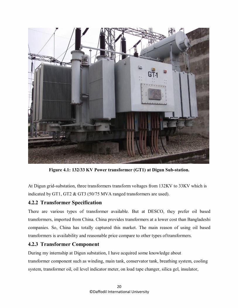
Figure 4.1: 132/33 KV Power transformer (GT1) at Digun Sub-station.
At Digun grid-substation, three transformers transform voltages from 132KV to 33KV which is
indicated by GT1, GT2 & GT3 (50/75 MVA ranged transformers are used).
4.2.2 Transformer Specification There are various types of transformer available. But at DESCO, they prefer oil based
transformers, imported from China. China provides transformers at a lower cost than Bangladeshi
companies. So, China has totally captured this market. The main reason of using oil based
transformers is availability and reasonable price compare to other types of transformers.
4.2.3 Transformer Component During my internship at Digun substation, I have acquired some knowledge about
transformer component such as winding, main tank, conservator tank, breathing system, cooling
system, transformer oil, oil level indicator meter, on load tape changer, silica gel, insulator,

21 ©Daffodil International University
radiator, oil temperature meter, and winding temperature meter, buchholz relay and pressure relief
device.
4.2.3.1 Winding: In figure (4.2), the primary winding is 33KV and secondary winding is 11KV.
In this case it is step-down transformer and that is why primary winding is Δ (delta) connected and
secondary winding is Y (wye) connected. The ac source is known as primary winding. The load
which is taken from the source is called secondary winding. The transformer consists of soft iron
core or the silicon steel core. Also two windings attached to it, they are primary winding and the
secondary winding. The windings are insulated from one another. The conducting material (a
conductor is a material which contains movable electric charges) used for the windings, depends
upon the application. But in all cases, each turns must be electrically insulated from each other to
ensure that the current travels throughout every turn.
Figure 4.2: Main tank with primary & secondary winding

22 ©Daffodil International University
4.2.3.2 Main Tank: Main tank is such type of protective element for the primary winding and
secondary winding. The end edge of the primary winding is connected from one side of the main
tank. And the starting edge of the secondary winding is connected from opposite site of the main
tank. Main tank is filled up with oil. And oil is used to provide insulation between the main tank
and the windings. The image of main tank along with primary and secondary winding is given in
figure (4.2).
4.2.3.3 Conservator Tank: During the expansion of oil due to internal fault of transformer or
when load increases, windings (both primary and secondary winding) produce more heat. As a
results oil volume can expand. And expansion of oil volume can enter from main to conservator
tank via buchholz relay. Actually the tank is designed as an expansion reservoir which allows the
expansion of the oil during operation. The image of conservator tank is given in figure (4.3).
Figure 4.3: Conservator tank at Digun Substation.
4.2.3.4 Buchholz Relay: Buchholz relay is a protective element of transformer. It is installed at
the middle position of the transformer tank and the conservator tank. When gas is produced inthe
main tank due to a minor fault, oil volume expands and can enter to conservator tank via buchholz
relay. If oil’s motion is very rapid, then at 1st, it gives the signal to the control room. If the fault is
very big then it trips the transformer. The image action of buchholz relay is given in figure 4.4.

23 ©Daffodil International University
Figure 4.4: Action of buchholz relay at Digun substation.
4.2.3.5 Cooling Equipment: The cooling equipment such as radiator collects the hot oil from the
top of the main tank and returns cooled oil lower down on the side of the main tank.
4.2.3.6 Winding Temperature and Oil Temperature Indicator: Winding temperature indicator
(meter) indicates the appropriate temperature of winding (The normal position of winding
temperature is 75 degree centigrade). Oil temperature indicator (meter) indicates the appropriate
temperature of oil (The normal position of oil temperature is 65 degree centigrade). The image of
oil temperature and winding temperature indicator is given in figure (4.5).
Figure 4.5: Winding temperature and oil temperature indicator.

24 ©Daffodil International University
4.2.3.7 On Load Tap Changer: On load tap changing is a mechanism that usually used in case
of any disturbance of primary winding or in case of any fault of actual incoming voltages to the
primary winding. In figure (3.6), the primary winding is 33KV and secondary winding is 11KV.
If 33KV is reduced at 28KV then on load tap changer is used to increase from 28KV to 33KV.
The image of on load tap changing mechanism is given in figure (4.6).
Figure 4.6 : Tap changing mechanism.
4.2.3.8 Transformer Oil: Transformer oil is used to provide insulation between the transformer
main tank and the windings (both primary windings and secondary windings) and for keeping cool
the transformer. The transformer oil also provides high dielectric strength to the coils and core
which are submerged. This allow transformer to be more compact and cost efficient.
4.2.3.9 Breathing System: Transformer breathing system is controlled by silica gel. It is used to
absorb moisture. During the injection of oil into transformer tank some air can enter or exit in the
conservator tank depending on expansion and extraction of the oil of main tank and silica gel is
used to absorb the moisture from that air. The image of silica gel is given in figure (4.7).

25 ©Daffodil International University
Figure 4.7: Transformer breathing system (silica gel) used at DESCO.
4.2.4 Losses in Transformer During my internship period at Digun grid-substation, I have acquired knowledge about
transformer losses. These are as follows:
Iron Losses: In actual iron cores, in-spite of lamination, some heat is still produced by the
eddy currents.
Copper Losses: In actual practice, coils of the transformer possess some resistance. So a part
of energy is lost due to heat produced by the resistance of the coils.
Hysteresis Losses: The alternating current in the coils repeatedly takes the iron core through
complete cycle of magnetization. So energy is lost due to hysteresis.
4.2.5 Protection Systems for transformer The principal relays and systems used for transformer protection at DESCO’s grid-substation are
described below.
• Buchholz devices providing protection against all kind of incipient fault i.e. slow –
developing faults such as insulation failure of windings, core heating, fall of oil level due
to leaky joints etc.

26 ©Daffodil International University
• Earth-fault relays providing against earth-faults only.
• Over current relays providing protection mainly phase-to-phase faults and overloading.
• Differential system (or circulating current system) providing protection against both earth and phase fault.
4.2.6 Auxiliary Transformers During my internship period at Digun grid-substation, I have seen two auxiliary transformers and
acquired knowledge about these. The grid-substation itself has a maintenance room beside it, so
the power supply of that household is provided through this auxiliary transformer. It provides the
supply to the auxiliary service which includes lighting, low voltage power supplies and ventilation.
The auxiliary service may be three-phase 440V or single phase 230V (Typical voltage rating
33KV/440V).
4.2.7 Circuit Breaker A circuit breaker is a switching device which can open and close a circuit in a small fraction of
second under normal as well as during fault condition. Basically, it is automatically operated by
electrical switch which is designed to protect an electrical circuit form damage caused by overload
or short circuit and its basic function is to detect a fault condition.
4.2.7.1 SF6 Gas Circuit breaker: During my internship period at Digun grid-substation, I have
seen four Sulphur Hexafluoride (SF6) gas circuit breaker and acquired knowledge about these. A
SF6 (Sulphur Hexafluoride) gas circuit breaker is a high voltage circuit breaker. Basically Sulphur
Hexafluoride (SF6) is an inert, heavy gas, having good dielectric and arc extinguishing properties.
It has high die-electric strength and outstanding arc quenching characteristics.
The followings are the advantages of SF6 gas circuit breaker:
Due to the superior arc quenching property of SF6, such breakers have very short arcing
time.
Since the dielectric strength of SF6 gas is 2 to 3 times that of air, such breakers can interrupt
large currents.
The SF6 gas circuit breaker gives noiseless operation due to its closed circuit.
There is no risk of fire in such breakers because SF6 as is non-inflammable.
The SF6 breakers have low maintenance cost, light foundation requirements and minimum
auxiliary equipment.
The image of SF6 gas circuit breaker is given in figure (4.8).
27 ©Daffodil International University
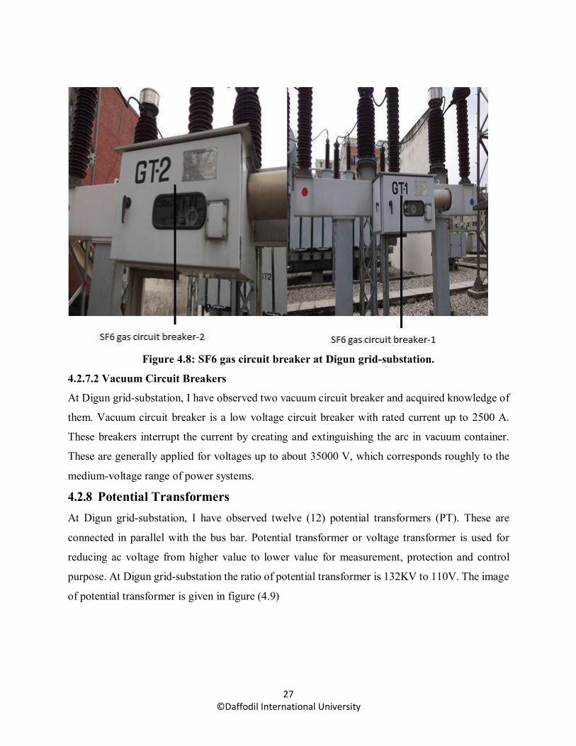
Figure 4.8: SF6 gas circuit breaker at Digun grid-substation.
4.2.7.2 Vacuum Circuit Breakers
At Digun grid-substation, I have observed two vacuum circuit breaker and acquired knowledge of
them. Vacuum circuit breaker is a low voltage circuit breaker with rated current up to 2500 A.
These breakers interrupt the current by creating and extinguishing the arc in vacuum container.
These are generally applied for voltages up to about 35000 V, which corresponds roughly to the
medium-voltage range of power systems.
4.2.8 Potential Transformers At Digun grid-substation, I have observed twelve (12) potential transformers (PT). These are
connected in parallel with the bus bar. Potential transformer or voltage transformer is used for
reducing ac voltage from higher value to lower value for measurement, protection and control
purpose. At Digun grid-substation the ratio of potential transformer is 132KV to 110V. The image
of potential transformer is given in figure (4.9)

28 ©Daffodil International University
Figure 4.9: Potential transformer at Digun grid-substation.
4.2.9 Current Transformers At Digun grid-substation, I have observed twelve (12) current transformers (CT). These are
connected in series with the bus bar. Current transformers (CT) are also used for reducing ac
current from higher value to lower value for measurement, protection and control purpose. At
Digun grid-substation the ratio of current transformer is (1800/900/1) Ampere. The image of
current transformer is given in figure (4.10).
Figure 4.10: Current transformer at Digun grid-substation.
29 ©Daffodil International University
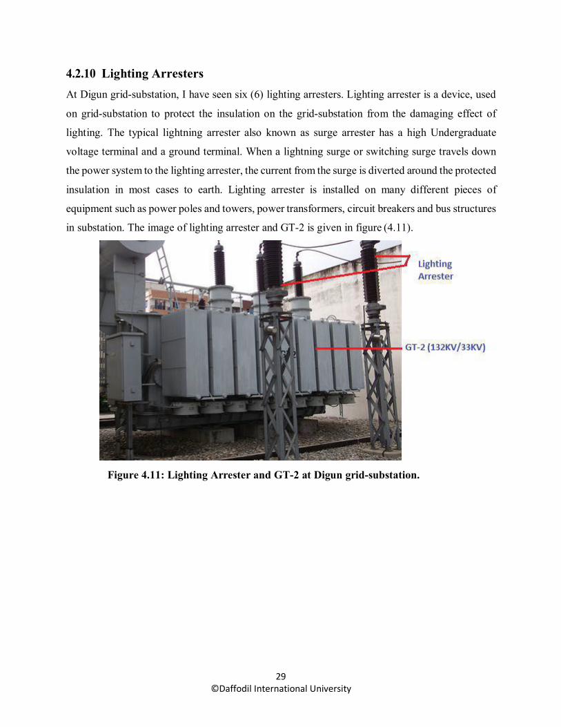
4.2.10 Lighting Arresters At Digun grid-substation, I have seen six (6) lighting arresters. Lighting arrester is a device, used
on grid-substation to protect the insulation on the grid-substation from the damaging effect of
lighting. The typical lightning arrester also known as surge arrester has a high Undergraduate
voltage terminal and a ground terminal. When a lightning surge or switching surge travels down
the power system to the lighting arrester, the current from the surge is diverted around the protected
insulation in most cases to earth. Lighting arrester is installed on many different pieces of
equipment such as power poles and towers, power transformers, circuit breakers and bus structures
in substation. The image of lighting arrester and GT-2 is given in figure (4.11).
Figure 4.11: Lighting Arrester and GT-2 at Digun grid-substation.

30 ©Daffodil International University
Figure 4.12: Lighting arrester indicator at Digun grid-substation.
4.2.11 Isolators At Digun grid-substation, I have seen different types of isolators. These are line isolator, bus
isolator, earth isolator, pin isolator and post isolator. Isolators are used to break the 3 phase power
circuit under no load condition. These are (mostly in substation) installed before and after the
transformer maintenance purpose. Basically it is used to disconnect a component of electrical
systems from the power source. Isolator switch is used to make sure that an electrical circuit can
be completely de-energized for service or maintenance. It operates only on “no load” condition
since there is no ability for arc extinguishing.
4.2.12 Bus Bars and Bus Coupler At Digun grid-substation, I have seen three (3) bus bars. These are 33 KV reserve bus, 33 KV main
bus, and 11KV bus. Actually bus bar is a strip of copper or aluminum that conducts electricity
within a switch board, distribution board, substation or other electrical apparatus. The size of the
bus bar determines the maximum amount of current that can be safely carried. Generally, it consists
of two bus-bars a main bus bar and a reserve bus bar. The incoming and outgoing lines can be
connected together in bus bar. However, in case of repair of main bus-bar or fault accusing on it,
the continuity of supply to the circuit can be maintained by transforming it to the reserve bus-bar.
Bus coupler is used to run the both bus (main bus and reserve bus) at the same time. The image of
bus bar and bus coupler is given in figure 4.13.

31 ©Daffodil International University
Figure 4.13: 132 KV bus bars and bus coupler at Digun grid-substation.
4.2.13 Battery and Battery Charger Battery is the heart of Substation. Battery is a storage device. It is required for back-up dc supply
to ensure protection. Battery supplies 110V dc voltage to the control and protection circuit when
ac fails or charger fails. In a substation, dc Voltage is required for protection, control and signaling.
Battery charger rectifies the 400V ac into 110V dc and supplies the dc voltage to control panels
for the mentioned purpose as well as charges the batteries. The image of battery and battery charger
is given in figure 4.14.
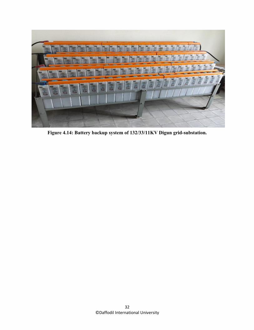
32 ©Daffodil International University
Figure 4.14: Battery backup system of 132/33/11KV Digun grid-substation.

33 ©Daffodil International University
CHAPTER 5 MAINTENANCE & PROTECTION
OF SUBSTATION 5.1 Maintenance and Inspection of Substation During my internship period at DESCO, I have got various ideas about substation’s equipment
maintenance and practically observed maintenance period of Digun substation. Basically there are
many inspections of substations, but DESCO implements inspection of substation’s equipment on
monthly and half-yearly basis. At Digun substation there are three 33 KV incoming sources and
twenty one outgoing feeders. Some transformers directly transform voltages from 33KV to 440V
and some transformers transform voltages from 33KV to 11KV. At Digun Substation there have
fourteen numbers of 11KV outgoing feeders are active.
Figure 5.1: Single Line Diagram of Digun Substation.
34 ©Daffodil International University
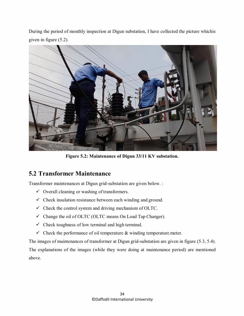
During the period of monthly inspection at Digun substation, I have collected the picture whichis
given in figure (5.2).
Figure 5.2: Maintenance of Digun 33/11 KV substation.
5.2 Transformer Maintenance Transformer maintenances at Digun grid-substation are given below. :
Overall cleaning or washing of transformers.
Check insulation resistance between each winding and ground.
Check the control system and driving mechanism of OLTC.
Change the oil of OLTC (OLTC means On Load Tap Changer).
Check toughness of low terminal and high terminal.
Check the performance of oil temperature & winding temperature meter.
The images of maintenances of transformer at Digun grid-substation are given in figure (5.3, 5.4).
The explanations of the images (while they were doing at maintenance period) are mentioned
above.

35 ©Daffodil International University
Figure 5.3: Checking insulation resistance between each winding & ground by using megar
meter.

36 ©Daffodil International University
Figure 5.4: Checking control system & driving mechanism of On Load Tap Changer.
5.3 Transformer Fault Detection and Repairing On August 28, 2017, I have visited the transformer repairing section at Digun substation with Sub-
divisional Manager, Md.Kamrul Islam (Rupnagar Sales & Distribution division). He explained me
about the common faults of transformer which are given below:
Transformer coil burn.
Drop off fuse.
Low dielectric strength in transformer oil.
5.3.1 Transformer Coil Burn: Coil burn process happens when distribution transformer runs under overload for long days. For
detecting transformer fault, at first the ‘insulation tester’ is used. This insulation tester measures
the resistance of transformer insulation. This tester has a prime mover, mega Ω meter and two
probes. To test the transformer insulation, one probe is connected to high side and another one to
low side. Then the prime mover is rotating by 120 rpm (rotating per minute) and produces very
low current follow like 100V. If the meter shows the resistive value less than 5 MΩ, it means coil
is burned, otherwise the tester shows more or equal to 30 MΩ. The image of distribution
transformer is given in figure 5.5.

37 ©Daffodil International University
Figure 5.5: The 11KV/440KV distribution transformer.
5.3.2 Drop off Fuse: Drop off fuse is a protection to protect transformer from burning. It is used, when transformer’s
distribution or feeder lines falls in short circuit or ground fault.
Figure 5.6: Drop out Fuse under Digun Feeder.

38 ©Daffodil International University
5.3.3 Low Dielectric Strength: One kind of oil is used in transformer to isolate the coil-container and to keep cool the transformer.
This oil is a dielectric material. If the oil dielectric value decreases, the core can be burned or a
serious accident could be occurred. So, DESCO usually checks the oil dielectric strength in every
two or three years ever since the transformer is installed.
5.4 Power Factor Monitoring & Upgrading Power factor monitoring is one of the most important factors in power system. Because poor power
factor imposes low effects on power generation. At substation I have seen the power factor was
about 0.97≈0.98, but usually the average is about 0.95. Inductive load is responsible to degrade
the power factor. We know that power factor is defined as the ratio of KW to KVA. But we can
see that the cause of low power factor is large KVAR. And we know that the magnitude of KVAR
is proportional to inductive load. All big factories, industries and workshops are main sources of
inductive loads. Inductive load includes: Transformer, Induction motor and Energy saving light.
Reactive power increases the amount of apparent power. This increases the reactive power and as
a result apparent power creates large angle (θ) between KW and KVA and larger angle produces
poor power factor (pf = cosθ).
5.4.1 Effect of Low Power Factor: Poor power factor affects the power distribution system, loss in distribution network and voltage
drop in feeder line. Excessive voltage drop may cause over heating in distribution network. Poor
power factor also affects the generation plant. The power generators act as an induction machine.
The reactive power comes from these power generators. Poor power factor means more reactive
power. More reactive power overloads the generators.
5.5 Control Room Activity I have spent four hours at Mirpur section-6 substation’s control room. Actually control room is
very important in power system. This control room is open for 7 days and 24 hours. The basic
operations of a control room are as follows:
Communicates with other control rooms or grids.
Communicates with line maintenance teams.
Manage load shedding.
Maintain VIP feeder with intentness.

39 ©Daffodil International University
Record data (Supply load, Demand load, Load Shedding time, Trip timing, Visitor
etc).
Figure 5.7: Control room at substation
Control relay panels facilitate centralized control of the related controlled equipment in power
stations, switching stations and industrial plant. The panels are bolted together to form a board.
This approach permits replacements, extensions and rearrangement when necessary. The panel
incorporates control switches and indicator lamps for remote control of controlled equipment. A
“remote/ supervisory” selector switch is also provided for selection of supervisory control from
remote control center.
5.6 Incoming Panels or Lines The equipment of 33KV incoming panels are trip circuit supervision relay-1, trip circuit
supervision relay-2, trip relay, bus isolator, ac alarm, dc alarm, on lamp, off lamp, line isolator,
earth isolator, dir. O/C and E/F relay, multifunction meter, KWH meter and also indicator signal.
The image of 33KV incoming panel with relay protection is given in figure (5.8).

40 ©Daffodil International University
Figure 5.8: The relay protection on 33KV incoming line at Digun substation.
5.6.1 Relay Protection on 33KV Incoming Line: At Digun substation’s control room inside the 33KV incoming panel there are two trip circuit
supervision relays, one trip relay, one bus isolator, one-line isolator and one earth isolator which I
have observed and acquired knowledge during my internship period. Trip circuit supervision relay-
1 is the relay which supervises the trip circuit of the circuit breaker. It tests whether dc supply is
under proper condition or not. It also provides alarm for loss of dc supply, faults in trip coil or
cables, faults on the breaker auxiliary contacts and faults in the relay itself. Trip circuit supervision
relay-2 is also used for same objective. Bus isolator is used to isolate the bus from incoming line
due to the maintenance or service purposes of bus. Line isolator is used to isolate the incoming
line due to the maintenance or service purpose of substation.
5.6.2 Earth Isolator: After closing the bus isolator and line isolator, some electric charge remains present in cables.
Actually earth isolator is used to discharge the electric charge from the cables. Master trip relay is
the main and backup for protection relay for trip circuit supervision relay.

41 ©Daffodil International University
5.7 The 33 KV Transformer Control Panels At Digun substation, I have observed three transformer control panels. These are transformer
control panel-1, transformer control panel-2 and transformer control panel-3. The equipment at
33KV transformer control panel are differential relay, sensitive earth fault relay (p-120), O/C and
E/F relay (p-120), multifunction meter, energy (KWH) meter, spring charge lamp, trip lamp, trip
coil-1, healthy lamp, trip coil-2, healthy lamp, dc-1, dc-2, spare, trip relay-1, trip relay-2, trip
circuit supervision relay-1, trip circuit supervision relay-2, auxiliary relay-1 (BZ main tank and
PRD main tank), auxiliary relay-2 (WTT and OLT), auxiliary relay-3 (BZ OLTC and PRD OLTC).
The image of digital relay protection is given in figure 5.9.
Figure 5.9: The digital relay protection on 33KV transformer panel.
During my internship at Digun substation, I have observed and acquired knowledge about the
differential relay, sensitive earth fault relay multifunction meter and O/C (over current) and E/F
(earth fault) relay of transformer control panel. Actually transformer differential relay is a relay
that checks for current balance between the primary and the secondary side of a transformer. It
also acts as a protective element to protect cables which finds the fault or the difference between
the primary and secondary current. The sensitive earth fault relay of power transformer is a
protective device that works by measuring the amount of lick current which discharges to the earth
such as for any small lick at underground cables and some current are discharging to the ground

42 ©Daffodil International University
of earth. But it has a limitation. If it crosses the limit current, the sensitive earth fault relay trips
the transformer. Multifunction meter is a meter which can display voltage, current, power factor,
line to line voltage, phase to phase voltage and phase to neutral voltage. O/C means over current
relay and E/F earth fault relay. O/C relay, if there is any imbalance in the 3 phase current then the
over current relay trips the circuit. During storms, if the phase falls down to the earth, then the
earth fault relay trips the circuit. The image of relay protection on 33KV transformer panel is given
in figure 5.9.
Figure 5.10: The relay protection on 33KV transformer panel at Digun substation.
Relay Protection on 33KV Transformer Panel: At Digun substation’s control room inside the
33KV transformer panel, there are two trip circuit supervision relays, two trip relays and three
auxiliary relays which I have observed during my internship period. Trip circuit supervision relay-
1 is the relay which supervises the trip circuit of the circuit breaker. It controls the dc supply of
trip circuit. It also provides alarm for loss of dc supply, faults in trip coil or cables and faults on
the breaker auxiliary contacts. Trip circuit supervision relay-2 is also used for same objective. The
auxiliary relay-1 trips the transformer when there is fault inside the buchholz’s main tank and
pressure relief device’s main tank. The auxiliary relay-2 trips the transformer when there is fault
inside the winding temperature thermometer and oil level thermometer. The auxiliary relay-3 trips
43 ©Daffodil International University
the transformer when there is fault inside the on load tap changer. Master trip relay is the main and
backup protection relay for trip circuit super vision relay. If the trip circuit supervision relay-1 and
relay-2 are unable to detect the fault or unable to sense the fault, then the master trip relay must
detect the fault and trip the transformer.
5.8 Outgoing Feeders At Digun substation there are eighteen numbers of 11KV outgoing feeders. But four numbers of
11KVoutgoing feeders are closed or spare for requirement of future generation, two number of
outgoing feeders are switching station and twelve numbers of 11KV outgoing feeders are active
for the distribution of electricity.
44 ©Daffodil International University
CHAPTER 6 NUMERICAL DATA ANALYSIS
6.1 Introduction
Numerical Data Analysis is very important and only main progress for a sub-station because
Analysis of data is a process of inspecting, cleaning, transforming, and modeling data with the
goal of discovering useful information, suggesting conclusions, and supporting decision-making.
Data analysis has multiple facets and approaches, encompassing diverse techniques under a variety
of names. during our internship period we have collect different type of data of Digun 33/11KV
substation. they are given below
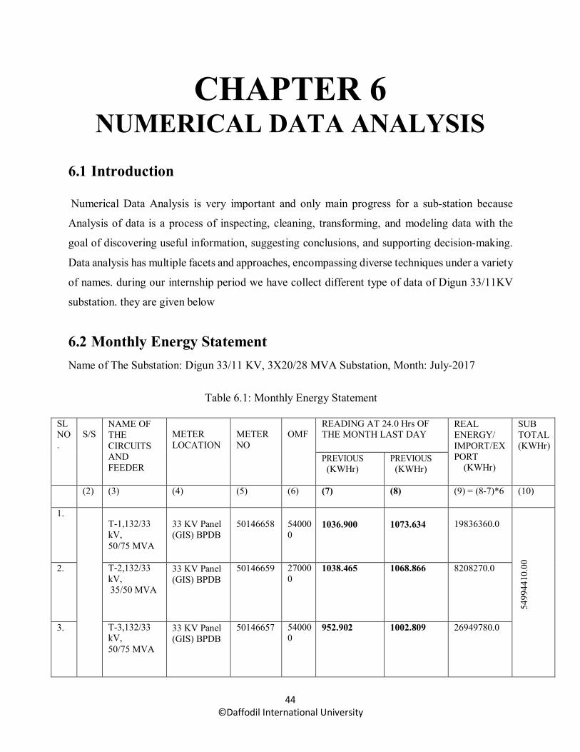
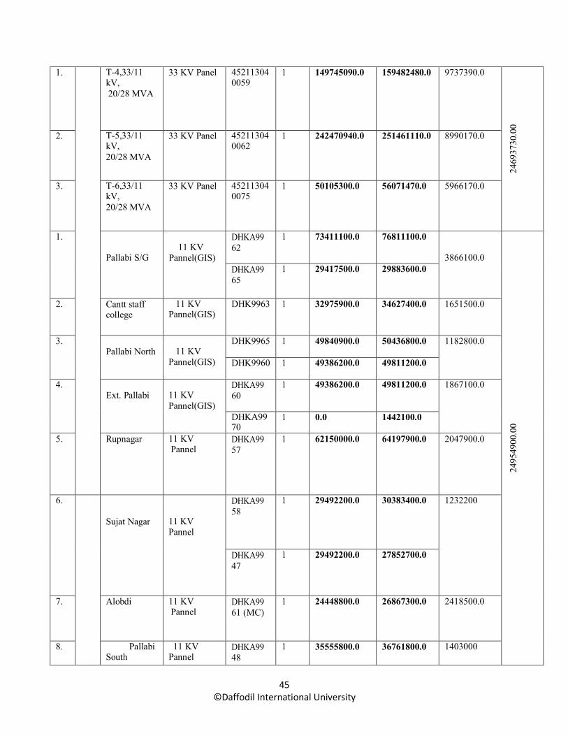
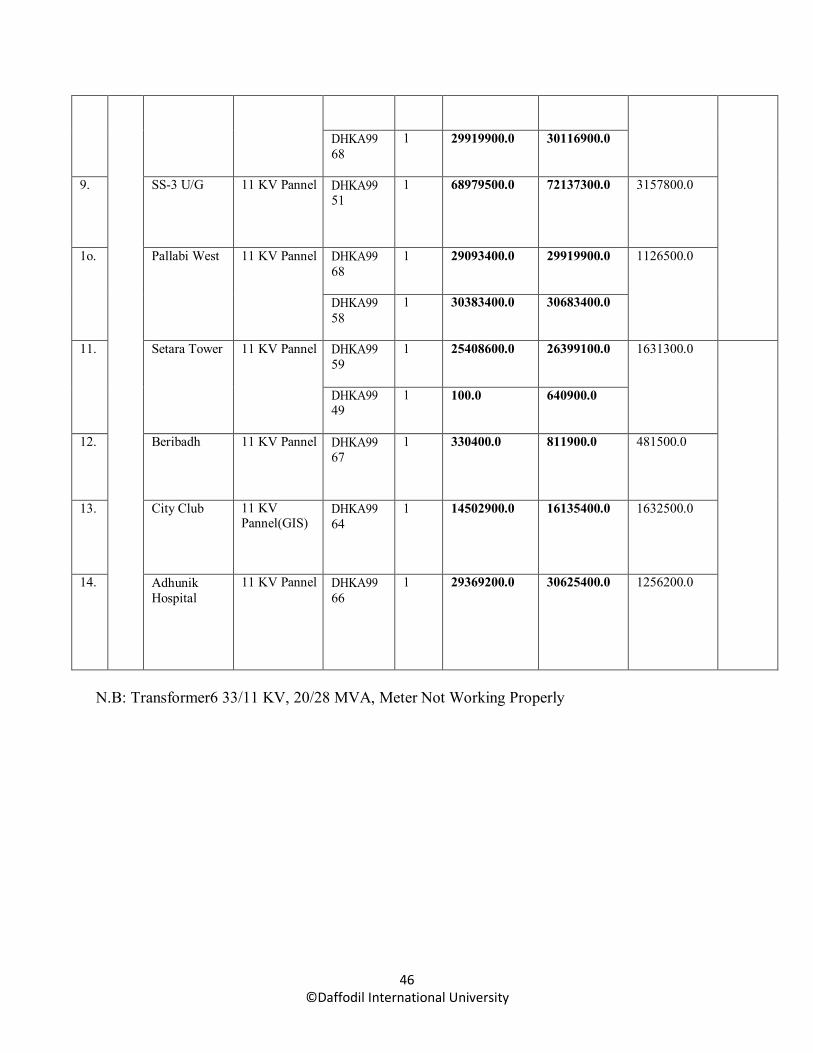
6.2 Monthly Energy Statement Name of The Substation: Digun 33/11 KV, 3X20/28 MVA Substation, Month: July-2017
Table 6.1: Monthly Energy Statement
SL NO .
S/S
NAME OF THE CIRCUITS AND FEEDER
METER LOCATION
METER NO
OMF
READING AT 24.0 Hrs OF THE MONTH LAST DAY
REAL ENERGY/ IMPORT/EX PORT
(KWHr)
SUB TOTAL (KWHr)
PREVIOUS (KWHr)
PREVIOUS (KWHr)
(2) (3) (4) (5) (6) (7) (8) (9) = (8-7)*6 (10)
1. T-1,132/33 kV, 50/75 MVA
33 KV Panel (GIS) BPDB
50146658
54000 0
1036.900
1073.634
19836360.0
5499
4410
.00
2. T-2,132/33 kV, 35/50 MVA
33 KV Panel (GIS) BPDB
50146659 27000 0
1038.465 1068.866 8208270.0
3. T-3,132/33 kV, 50/75 MVA
33 KV Panel (GIS) BPDB
50146657 54000 0
952.902 1002.809 26949780.0
45 ©Daffodil International University
1. T-4,33/11 kV, 20/28 MVA
33 KV Panel 45211304 0059
1 149745090.0 159482480.0 9737390.0
2469
3730
.00
2. T-5,33/11 kV, 20/28 MVA
33 KV Panel 45211304 0062
1 242470940.0 251461110.0 8990170.0
3. T-6,33/11 kV, 20/28 MVA
33 KV Panel 45211304 0075
1 50105300.0 56071470.0 5966170.0
1.
Pallabi S/G
11 KV
Pannel(GIS)
DHKA99 62
1 73411100.0 76811100.0
3866100.0
2495
4900
.00
DHKA99 65
1 29417500.0 29883600.0
2. Cantt staff college
11 KV Pannel(GIS)
DHK9963 1 32975900.0 34627400.0 1651500.0
3. Pallabi North
11 KV
Pannel(GIS)
DHK9965 1 49840900.0 50436800.0 1182800.0
DHK9960 1 49386200.0 49811200.0
4. Ext. Pallabi
11 KV Pannel(GIS)
DHKA99 60
1 49386200.0 49811200.0 1867100.0
DHKA99 70
1 0.0 1442100.0
5. Rupnagar 11 KV Pannel
DHKA99 57
1 62150000.0 64197900.0 2047900.0
6.
Sujat Nagar
11 KV Pannel
DHKA99 58
1 29492200.0 30383400.0 1232200
DHKA99 47
1 29492200.0 27852700.0
7. Alobdi 11 KV Pannel
DHKA99 61 (MC)
1 24448800.0 26867300.0 2418500.0
8. Pallabi South
11 KV Pannel
DHKA99 48
1 35555800.0 36761800.0 1403000
46 ©Daffodil International University
DHKA99 68
1 29919900.0 30116900.0
9. SS-3 U/G 11 KV Pannel DHKA99 51
1 68979500.0 72137300.0 3157800.0
1o. Pallabi West 11 KV Pannel DHKA99 68
1 29093400.0 29919900.0 1126500.0
DHKA99 58
1 30383400.0 30683400.0
11. Setara Tower 11 KV Pannel DHKA99 59
1 25408600.0 26399100.0 1631300.0
DHKA99 49
1 100.0 640900.0
12. Beribadh 11 KV Pannel DHKA99 67
1 330400.0 811900.0 481500.0
13. City Club 11 KV Pannel(GIS)
DHKA99 64
1 14502900.0 16135400.0 1632500.0
14. Adhunik Hospital
11 KV Pannel DHKA99 66
1 29369200.0 30625400.0 1256200.0
N.B: Transformer6 33/11 KV, 20/28 MVA, Meter Not Working Properly

47 ©Daffodil International University
6.3 LOSSES 6.3.1 losses in 11 KV side transformer-4 Name of the substation: digun 333/11 KV,3x20/28 MVA substation month: july-2017
Table 6.2: losses in 11 KV side transformer-4
SL NO .
S/S NAME OF THE CIRCUITS AND FEEDER
METER LOCATION
METER NO OMF READING AT 24.0 Hrs OF THE MONTH LAST DAY
REAL ENERGY/ IMPORT/ EXPORT (KWHr)
SUB TOTAL (KWHr)
PREVIOUS (KWHr)
PRESENT (KWHr)
(2) (3) (4) (5) (6) (7) (8) (9)=(8-7)*6 (10)
1. T-4,33/11 kV, 20/28 MVA
33 KV Panel 45211304005 9
1 149745090. 0
159482480.0 9737390.0
9737
390.
0
1.
Pallabi S/G
11 KV
Pannel(GIS)
DHKA9962 1 73411100.0 76811100.0 3866100.0
9589
100.
00
DHKA9965 1 29417500.0 29883600.0
2. Cantt staff college
11 KV Pannel(GIS)
DHK9963 1 32975900.0 34627400.0 1651500.0
3. Pallabi North
11 KV
Pannel(GIS)
DHK9965 1 49840900.0 50436800.0 1182800.0
DHK9960 1 49386200.0 49811200.0
4. City Club 11 KV Pannel(GIS)
DHKA9964 1 14502900.0 16135400.0 1632500.0
5. Adhunik Hospital
11 KV Pannel DHKA9966 1 29369200.0 30625400.0 1256200.0
N.B 1. 11 kV Pallabi Feeder energized at 01/08/2017 Both end meter not work.

48 ©Daffodil International University
6.3.2 losses in 11 KV side transformer-5 Name of the substation: digun 33/11 KV,3x20/28 MVA substation month: july-2017
Table6.3 losses in 11 KV side transformer 5.
SL NO .
S/S NAME OF THE CIRCUITS AND FEEDER
METER LOCATION
METER NO OMF READING AT 24.0 Hrs OF THE MONTH LAST DAY
REAL ENERGY/ IMPORT/ EXPORT (KWHr)
SUB TOTAL (KWHr)
PREVIOUS (KWHr)
PRESENT (KWHr)
(2) (3) (4) (5) (6) (7) (8) (9)=(8-7)*6 (10)
1. T-5,33/11 kV, 20/28 MVA
33 KV Panel 45211304006 2
1 242470940. 0
251461110. 0
8990170.0
8990
170.
0
1. Rupnagar 11 KV Pannel DHKA9957 1 62150000.0 64197900.0 2047900.0
8967
400.
00
2. Sujat Nagar
11 KV Pannel
DHKA9958 1 29492200.0 30383400.0 1232200
DHKA9947 1 29492200.0 27852700.0
3. Pallabi South
11 KV Pannel
DHKA9948 1 35555800.0 36761800.0 1403000
DHKA9968 1 29919900.0 30116900.0
4. SS-3 U/G 11 KV Pannel DHKA9951 1 68979500.0 72137300.0 3157800.0
5. Pallabi West
11 KV Pannel
DHKA9968 1 29093400.0 29919900.0 1126500.0
DHKA9958 1 30383400.0 30683400.0

49 ©Daffodil International University
6.4 Electricity Tariff in Bangladesh
In Bangladesh there have used both flat rate or single rate tariffs and time of use tariffs at various
sector which kinds of tariffs are consideration
6.4.1 Tariff Rate This is for information of all concerned that in accordance with the BERC Order # BERC/ Tariff/
Bitoron-10/desco/ongsho-02/3059 Dated: 27 August 2015, the new tariff rates with respect to
retail sales of electricity of Dhaka Electric Supply Company Ltd. (DESCO) has been made
effective from bill month September 2015 as the following:
Table6.4: Tariff Rate with Respect to Retail Sales
SL Customer Category Per Unit
Rate (Tk.)
Minimum Charge
Demand Charge
Service Charge
1ph
Service Charge
3ph
1 Category-A : Residential
Life Line : From 1 to 50 units 3.33
100
15
10
30
a. First Step : From 1 to 75 units 3.80 b. Second Step : From 76 to 200 units 5.14 c. Third Step : From 201 to 300 units 5.36 d. Fourth Step: From 301 to 400 units 5.63 e. Fifth Step: From 401 to 600 units 8.70 f. Sixth Step: Above 600 units 9.98
2 Category-B : Agricultural pumping 3.82 125 30 40 3 Category-C : Small Industries
a. Flat Rate 7.66 - 40 70 b. Off-Peak Time 6.90 c. Peak Time 9.24
4 Category-D : Non-Residential (Light & Power) 5.22 100 20 10 30 5 Category-E : Commercial And Office
a Flat Rate 9.80 125 25 10 30 b Off-Peak Time 8.45 c Peak Time 11.98
6 Category-F : Medium Voltage, General Purpose (11 KV) a Flat Rate 7.57 8000 45 400 b Off-Peak Time 6.88 c Peak Time 9.57
7 Category-H : High Voltage, General Purpose (33 KV) a Flat Rate 7.49 80 40 450 b Off-Peak Time 6.82 c Peak Time 9.52
8 Category-J : Street Light and Water Pump 7.17 100 20 10 30

50 ©Daffodil International University
6.5 Date of Check: T-4 Transformer at 20/08/2017& T-5 Transformer at 21/08/17
Table6.5: Checking of Transformer
SL No.
Maintenance Work Condition Action taken Remarks
1 General Cleaning Done
Indoor Type
2 Silica gel breather Good
3 Silica gel Color White Changed
4
Tran
sfor
mer
Oil
a) Oil Level Low (T-4) 01 Barrel Filled (T-4)
b) Dielectric Strength 51 KV(Avg.) Tested Result another sheet
c) Oil Leakage T-4 Oil leak Repaired
5 Oil temperature meter Good
6 Oil level Indicator Good
7 Winding temperature meter Good
8 Cooling fan cleaning Done
9 Cooling fan motor Good
10
H.T
. B
ushi
ng a) Physical Condition Good
b) Horn gap Good
11
L.T.
B
ushi
ng a) Physical Condition Good
b) Horn gap N/A
12 Radiator Good
13 Tap Changer mechanism Good
14 Lightning Arrester Good cleaning is done
15
Prot
ectio
n Sy
stem
a) Buchholtz Relay(MainTank) Trip- OK
b) Buchholtz Relay (Tap changer) Trip- OK
c)Winding Temp (HV) Trip- OK d) Winding Temp (LV) Trip- OK
e) PRD Protection Trip- OK

51 ©Daffodil International University
6.6 Insulation Resistance Test Applied voltage 5650 V, weather: sunny, Oil temp: 38˚C
Table 6.6: Test of Insulation
Name of Transformer
Mode of connection Insulation Resistance Remarks
15 Sec 60 Sec
T-4
HT-G 10.4 GΩ 4.6 GΩ
With 11 kV Cable connected
LT-G 6.66 GΩ 11.6 GΩ
HT-LT 16.3 GΩ 19.8 GΩ
T-5
HT-G 10 GΩ 23 GΩ
LT-G 5 GΩ 11 GΩ
HT-LT 14 GΩ 25 GΩ
6.7 11 KV Breaker Test Report(Area) 6.7.1 General Check
Table 6.7: General Checking of Breaker
SL NO.
MAINTENANCE WORK CONDITION ACTION TAKEN REMARK
1. General Cleaning Done
2. Position Indication Signal Good √
3. Bushing Good √
4. Operation Good √
5. Manual Operation System Good √
6. Electrical Operation System Good √

52 ©Daffodil International University
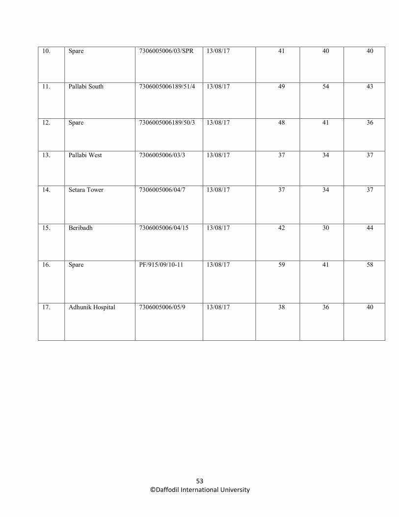
6.7.2 Contract Resistance Test of 11 KV Breaker
Applied Current :100 A Table6.8: Contract Resistance Test
SL NO.
FEDER NAME.
BREAKER SEREIAL NO.
DATE OF TEST
RESULT
R-R(µΩ) Y-Y(µΩ) B-B(µΩ)
1. T-4,33/11 KV, 20/28 MVA
7306005006/04/17 13/08/17 58 18 30
2. T-5,33/11 KV, 20/28 MVA
7306005009/04/20 13/08/17 54 22 32
3. T-6,33/11 KV, 20/28 MVA
7306005008/04/19 13/08/17 50 23 33
4. Pallabi S/G 73060052006189/51/4 13/08/17 59 42 40
5. Cantt staff college 7306005006/6/5 13/08/17 39 47 41
6. Pallabi North 7306005006/03/11 13/08/17 24 39 40
7. Ext. Pallabi 7306005006/06/3 13/08/17 24 21 22
8. Rupnagar 7306005006/04/18 13/08/17 41 47 39
9. Sujat Nagar 7306005006/05/9 13/08/17 39 48 41
53 ©Daffodil International University
10. Spare 7306005006/03/SPR 13/08/17 41 40 40
11. Pallabi South 7306005006189/51/4 13/08/17 49 54 43
12. Spare 7306005006189/50/3 13/08/17 48 41 36
13. Pallabi West 7306005006/03/3 13/08/17 37 34 37
14. Setara Tower 7306005006/04/7 13/08/17 37 34 37
15. Beribadh 7306005006/04/15 13/08/17 42 30 44
16. Spare PF/915/09/10-11 13/08/17 59 41 58
17. Adhunik Hospital 7306005006/05/9 13/08/17 38 36 40
54 ©Daffodil International University
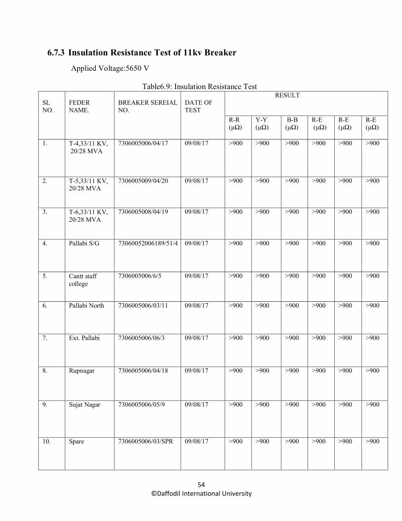
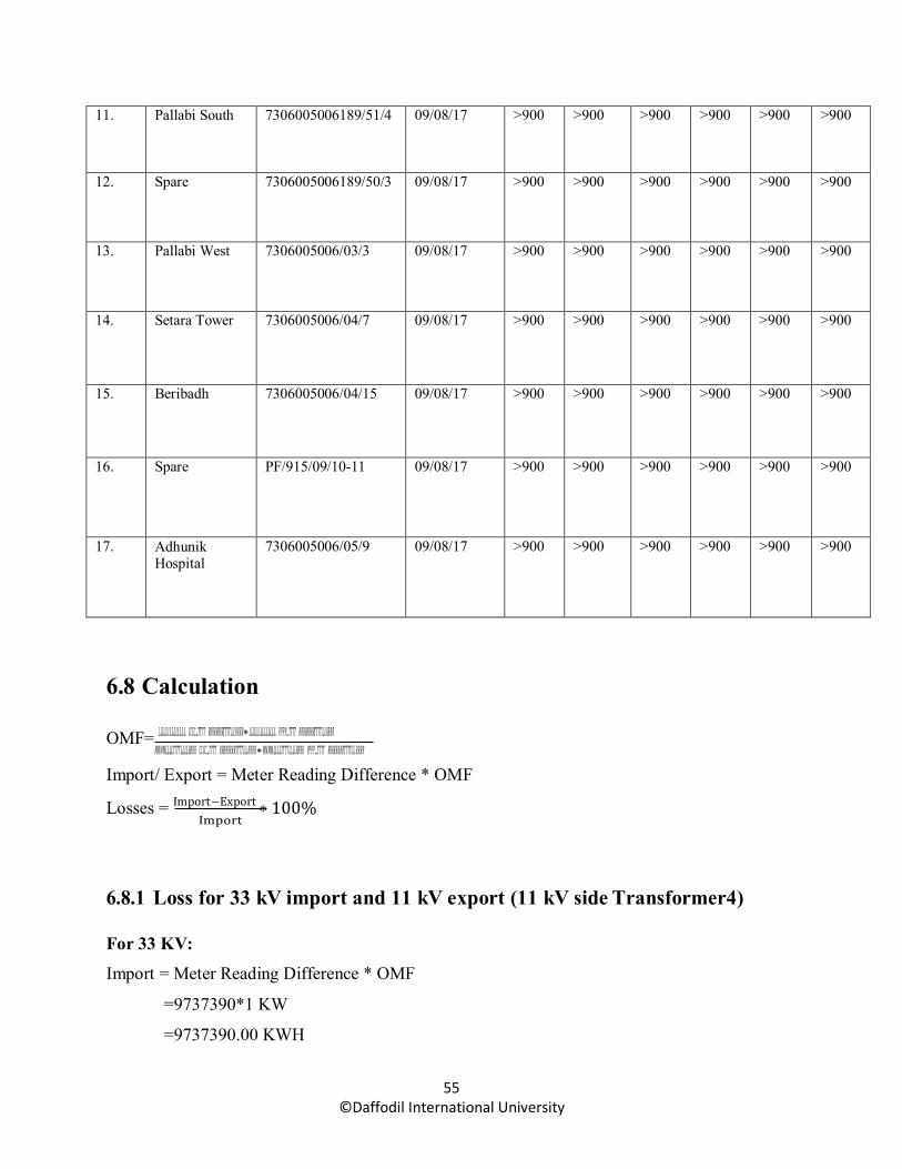
6.7.3 Insulation Resistance Test of 11kv Breaker
Applied Voltage:5650 V
Table6.9: Insulation Resistance Test
SL NO.
FEDER NAME.
BREAKER SEREIAL NO.
DATE OF TEST
RESULT
R-R (µΩ)
Y-Y (µΩ)
B-B (µΩ)
R-E (µΩ)
R-E (µΩ)
R-E (µΩ)
1. T-4,33/11 KV, 20/28 MVA
7306005006/04/17 09/08/17 >900 >900 >900 >900 >900 >900
2. T-5,33/11 KV, 20/28 MVA
7306005009/04/20 09/08/17 >900 >900 >900 >900 >900 >900
3. T-6,33/11 KV, 20/28 MVA
7306005008/04/19 09/08/17 >900 >900 >900 >900 >900 >900
4. Pallabi S/G 73060052006189/51/4 09/08/17 >900 >900 >900 >900 >900 >900
5. Cantt staff college
7306005006/6/5 09/08/17 >900 >900 >900 >900 >900 >900
6. Pallabi North 7306005006/03/11 09/08/17 >900 >900 >900 >900 >900 >900
7. Ext. Pallabi 7306005006/06/3 09/08/17 >900 >900 >900 >900 >900 >900
8. Rupnagar 7306005006/04/18 09/08/17 >900 >900 >900 >900 >900 >900
9. Sujat Nagar 7306005006/05/9 09/08/17 >900 >900 >900 >900 >900 >900
10. Spare 7306005006/03/SPR 09/08/17 >900 >900 >900 >900 >900 >900
55 ©Daffodil International University
11. Pallabi South 7306005006189/51/4 09/08/17 >900 >900 >900 >900 >900 >900
12. Spare 7306005006189/50/3 09/08/17 >900 >900 >900 >900 >900 >900
13. Pallabi West 7306005006/03/3 09/08/17 >900 >900 >900 >900 >900 >900
14. Setara Tower 7306005006/04/7 09/08/17 >900 >900 >900 >900 >900 >900
15. Beribadh 7306005006/04/15 09/08/17 >900 >900 >900 >900 >900 >900
16. Spare PF/915/09/10-11 09/08/17 >900 >900 >900 >900 >900 >900
17. Adhunik Hospital
7306005006/05/9 09/08/17 >900 >900 >900 >900 >900 >900
6.8 Calculation
OMF= 𝐿𝐿𝐿𝐿𝐿𝐿𝐿𝐿𝐿𝐿𝐿𝐿𝐿𝐿𝐿𝐿 𝐿𝐿𝐿𝐿𝐿𝐿𝐿𝐿𝐿𝐿𝐿𝐿𝐿𝐿𝐿𝐿 𝐶𝐶𝐶𝐶𝐶𝐶𝐶𝐶.𝑇𝑇𝑇𝑇𝑇𝑇𝑇𝑇 𝑅𝑅𝑅𝑅𝑅𝑅𝑅𝑅𝑅𝑅𝑅𝑅𝑅𝑅𝑅𝑅𝑇𝑇𝑇𝑇𝑇𝑇𝑇𝑇𝐿𝐿𝐿𝐿𝐿𝐿𝐿𝐿 𝑅𝑅𝑅𝑅𝑅𝑅𝑅𝑅∗𝐿𝐿𝐿𝐿𝐿𝐿𝐿𝐿𝐿𝐿𝐿𝐿𝐿𝐿𝐿𝐿 𝐿𝐿𝐿𝐿𝐿𝐿𝐿𝐿𝐿𝐿𝐿𝐿𝐿𝐿𝐿𝐿 𝑃𝑃𝑃𝑃𝑃𝑃𝑃𝑃.𝑇𝑇𝑇𝑇𝑇𝑇𝑇𝑇 𝑅𝑅𝑅𝑅𝑅𝑅𝑅𝑅𝑅𝑅𝑅𝑅𝑅𝑅𝑅𝑅𝑇𝑇𝑇𝑇𝑇𝑇𝑇𝑇𝐿𝐿𝐿𝐿𝐿𝐿𝐿𝐿 𝑅𝑅𝑅𝑅𝑅𝑅𝑅𝑅 𝑀𝑀𝑀𝑀𝑀𝑀𝑀𝑀𝐿𝐿𝐿𝐿𝐿𝐿𝐿𝐿𝑇𝑇𝑇𝑇𝑇𝑇𝑇𝑇𝐿𝐿𝐿𝐿𝐿𝐿𝐿𝐿𝑅𝑅𝑅𝑅𝑅𝑅𝑅𝑅 𝐶𝐶𝐶𝐶𝐶𝐶𝐶𝐶.𝑇𝑇𝑇𝑇𝑇𝑇𝑇𝑇 𝑅𝑅𝑅𝑅𝑅𝑅𝑅𝑅𝑅𝑅𝑅𝑅𝑅𝑅𝑅𝑅𝑇𝑇𝑇𝑇𝑇𝑇𝑇𝑇𝐿𝐿 𝐿𝐿𝐿𝐿𝐿𝐿 𝑅𝑅𝑅𝑅𝑅𝑅𝑅𝑅∗𝑀𝑀𝑀𝑀𝑀𝑀𝑀𝑀𝐿𝐿𝐿𝐿𝐿𝐿𝐿𝐿𝑇𝑇𝑇𝑇𝑇𝑇𝑇𝑇𝐿𝐿𝐿𝐿𝐿𝐿𝐿𝐿𝑅𝑅𝑅𝑅𝑅𝑅𝑅𝑅 𝑃𝑃𝑃𝑃𝑃𝑃𝑃𝑃.𝑇𝑇𝑇𝑇𝑇𝑇𝑇𝑇 𝑅𝑅𝑅𝑅𝑅𝑅𝑅𝑅𝑅𝑅𝑅𝑅𝑅𝑅𝑅𝑅𝑇𝑇𝑇𝑇𝑇𝑇𝑇𝑇𝐿𝐿𝐿𝐿𝐿𝐿𝐿𝐿 𝑅𝑅𝑅𝑅𝑅𝑅𝑅𝑅
Import/ Export = Meter Reading Difference * OMF
Losses = Import−Export ∗ 100%
Import
6.8.1 Loss for 33 kV import and 11 kV export (11 kV side Transformer4)
For 33 KV:
Import = Meter Reading Difference * OMF
=9737390*1 KW
=9737390.00 KWH
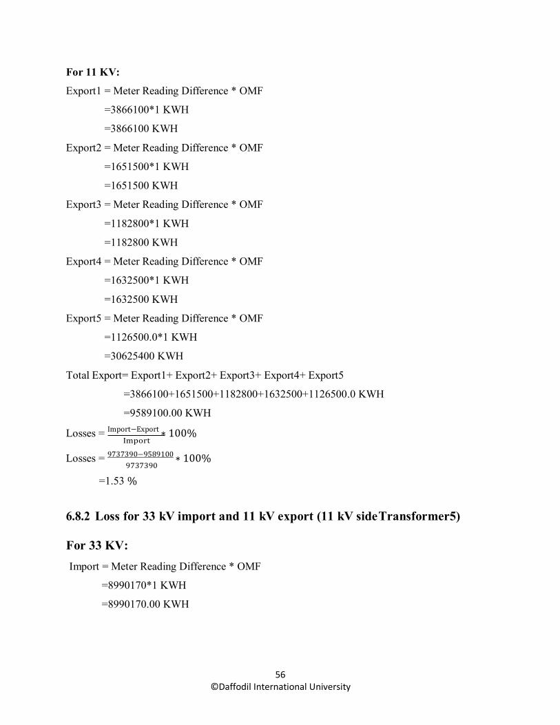
56 ©Daffodil International University
For 11 KV:
Export1 = Meter Reading Difference * OMF
=3866100*1 KWH
=3866100 KWH
Export2 = Meter Reading Difference * OMF
=1651500*1 KWH
=1651500 KWH
Export3 = Meter Reading Difference * OMF
=1182800*1 KWH
=1182800 KWH
Export4 = Meter Reading Difference * OMF
=1632500*1 KWH
=1632500 KWH
Export5 = Meter Reading Difference * OMF
=1126500.0*1 KWH
=30625400 KWH
Total Export= Export1+ Export2+ Export3+ Export4+ Export5
=3866100+1651500+1182800+1632500+1126500.0 KWH
=9589100.00 KWH
Losses = Import−Export ∗ 100% Import
Losses = 9737390−9589100 ∗ 100% 9737390
=1.53 %
6.8.2 Loss for 33 kV import and 11 kV export (11 kV side Transformer5)
For 33 KV: Import = Meter Reading Difference * OMF
=8990170*1 KWH
=8990170.00 KWH
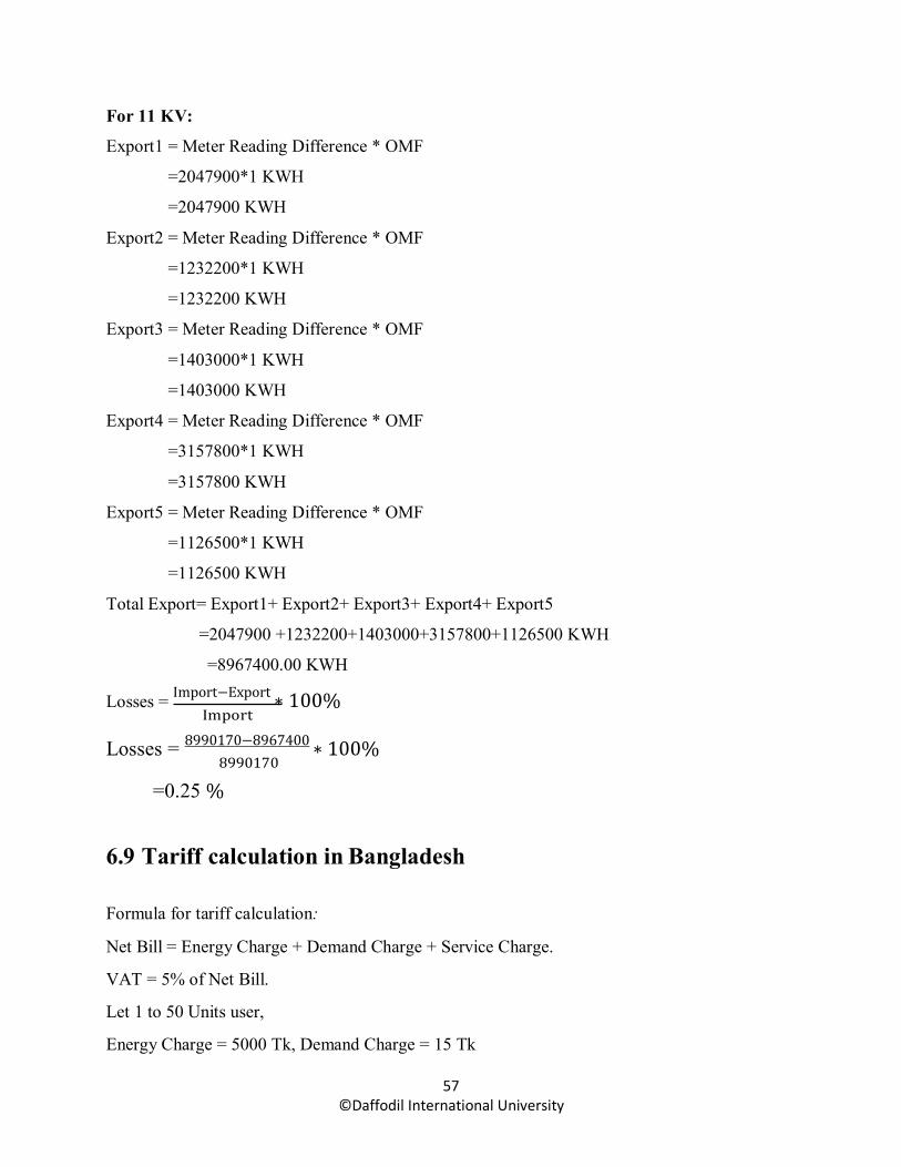
57 ©Daffodil International University
For 11 KV:
Export1 = Meter Reading Difference * OMF
=2047900*1 KWH
=2047900 KWH
Export2 = Meter Reading Difference * OMF
=1232200*1 KWH
=1232200 KWH
Export3 = Meter Reading Difference * OMF
=1403000*1 KWH
=1403000 KWH
Export4 = Meter Reading Difference * OMF
=3157800*1 KWH
=3157800 KWH
Export5 = Meter Reading Difference * OMF
=1126500*1 KWH
=1126500 KWH
Total Export= Export1+ Export2+ Export3+ Export4+ Export5
=2047900 +1232200+1403000+3157800+1126500 KWH
=8967400.00 KWH
Losses = Import−Export ∗ 100% Import
Losses = 8990170−8967400 ∗ 100% 8990170
=0.25 %
6.9 Tariff calculation in Bangladesh
Formula for tariff calculation:
Net Bill = Energy Charge + Demand Charge + Service Charge.
VAT = 5% of Net Bill.
Let 1 to 50 Units user,
Energy Charge = 5000 Tk, Demand Charge = 15 Tk

58 ©Daffodil International University
Service Charge = 10 Tk (For 1 Phase) and we consider there one hour in a day at 16.8.17
Therefore,
Net Bill = (5000 + 15 + 10) Tk
= 5025 Tk
Net Bill/Unit = 5025/1000 Tk
= 5.02 Tk/Unit
6.10 Insulation and Contact resistance calculation of Transformer & Breaker
6.10.1 Insulation resistance of Transformer T4 & T5
HT-LT = 30 MΩ (Allowable)
LT-G = 22 MΩ (Allowable)
HT-G = 66 MΩ (Allowable)
6.10.2 Insulation& Contact resistance of Breaker
Insulation Resistance > 900 μΩ (Allowable)
Contact Resistance > 100 μΩ (Allowable)
59 ©Daffodil International University
CHAPTER 7 RESULTS & DISCUSSION
7.1 Introduction This chapter will elaborate more on the findings gathered of this project. This chapter will perform
all the mechanism involved with the result refers to the theory. Base on the result occurred, we
would discuss about the performance of the full sub-station and any things that related with the
project.
7.2 Losses For 33 kV import and 11 kV export (11 KV side Transformer4) loss is 1.53%
Since Import = 9737390.00 KWh, Export = 9589100.00 KWh
That’s why loss coming is 1.53%
For 11 KV import and 11KV export (11 KV side Transformer5) loss is 0.25%
Since import = 8990170.00 KWh, Export = 8967400.00 KWh
That’s why loss coming is 0.25%
In generally losses must be small amount but there is huge amount loss in 11 kV side of
transformer4. Because 33 KV Pallabi feeder energized at end and meter not work, 11KV incomer-
1 meter not working, 33 KV bus PT burnt, Can’t get accurate data from meter reading. And there
have various faults especially like cable fault, Bus bar fault, CT & PT burnt. Sometimes it’s make
no sense when take meter reading. Sometimes meter not give accurate data for something fault.
So we not get desired output.
7.3 Tariff calculation At this stage we consider an hour in a day at 16.9.2017.
Taking service charge for 1phase consumer
The result is 5.02 Taka/Unit as an example.

60 ©Daffodil International University
7.4 Insulation and Contact resistance calculation of Transformer & Breaker:
Insulation resistance of Transformer T4 & T5:
HT-LT = 14 GΩ
LT-G = 5 GΩ
HT-G = 10 GΩ
Insulation & Contact resistance of Breaker:
Insulation Resistance= 58 μΩ(R-R), 18 μΩ (R-Y), 30 μΩ (R-B).
Contact Resistance = 100 μΩ (R-R), 100 μΩ(R-Y), 100 μΩ(R-Y).
7.5 Discussion In this section, first the data are presented in an orderly manner. Then they are discussed
individually. This section is most important part of the paper and should be as convincing as
possible. Here also is important to obtain some indication about how analyzable the results are.
While this is hard to check, one can look at the stability of the results.

61 ©Daffodil International University
CHAPTER 8 CONCLUSIONS
8.1 Conclusions A sub-station is very important place for an Electrical & Electronics Engineering where we can
know more details like as structure of transformer and working principle, difference between CT
& PT ratio and settings, bus bar system, incoming and outgoing cables, bushing, isolator, earthling
system, lightning arrester, DC battery control panel system, control and relay panel, synchronizing,
synchro scope, switch gear, GIS( Gas Insulated Switchgear), AIS( Air Insulated Switchgear),
Incoming feeder, and full control panel system. The Demand of electricity is increasing day by
day. But the rate of increase in production of electricity is not, sufficient with the demand in
Bangladesh. Substation in a company like Power man Bangladesh Ltd. Is too much important not
only for its own production but also it has a great impact in the economy of the whole country.
Like other fast growing industry or residential area it has a good demand of power. There are some
other aspects like incontinent source of energy. The local Electricity supply system is not secure
to run the factory itself. So, it has become must to be self-dependent substation to control flow of
power like Power man has its own. The practice should be done for the rest others ofBangladesh.
8.2 Limitations of the work Always hardware development is not possible, Because, there always running mechanical system,
and only some few times faced trouble-some problem if unnecessary worked has been done
suddenly.
For rules and regulation, we can’t collect some internal data because of their some internal &
external system like as, if they publish the data for all, then the government rules break dawn and
it is also very important that’s why every company or organization should have some regulation
otherwise it wouldn’t possible to run properly.
They have no enough manpower for guiding to us because low policy and their losses.
We can’t properly observe some equipment for restricted area because a sub-station is a very
dangerous and restricted area for the high voltage electricity which is very dangerous for un
experience person and outer person.

62 ©Daffodil International University
It was not possible to present a complete report like- statistics, financial involvement, costing, etc.
regarding the topic or the opportunity.
It had to be taken care of that the report does not contain any company confidential information
and harm the organization in their strategic stance.
8.3 Future Scopes of the Work Have to Increase man power in substation with good performance with proper experience.
Have to Digitalizing power distribution system with digital equipment’s because all digital
equipment’s are more benefited from analog system. Our thesis knowledge, enable us to build a
substation for building, industrial etc load. By Digitalizing PFI panel on a three phase load the
reactive power can be minimized. Knowledge about cost of installing a substation for a building
or industrial load. We have knowledge about the protection equipment of a substation which will
be necessary for installing a sub-station. We should expect that our theoretical observation can be
implemented practically install in any kind of substation to increase the efficiency of the
substation. During the training period we have learnt about power transmission system and
distribution system, controlling and operating breakers, isolators, acknowledge of alarm observing
the signal. It had also learnt about various maintenance like transformer dielectric strength of oil
test, insulation test of conductors etc. Everyone thinks DESCO should continue such Internship
opportunities. It will be a great help for students who are going to complete their degree of
Bachelor of Science in EEE.
If government give and should have to force for sub-station training for develop knowledge and
practical knowledge with good performance, then an engineering student know more with theory.

63 ©Daffodil International University
References
[1] https://en.wikipedia.org/wiki/Electricity_sector_in_Bangladesh
[2] http://www.powerdivision.gov.bd/user/brec/39/53
[3] https:// desco.org.bd
[4] https://www.desco.org.bd/?page=about-us
[5] https://www.desco.org.bd/index.php?page=vision-mission
[6] https://www.desco.org.bd/index.php?page=organogram
[7] https://www.desco.org.bd/index.php?page=org_md
[8] https://www.desco.org.bd/index.php?page=gm_admin
[9] https://www.desco.org.bd/index.php?page=gm_fin
[10] https://www.desco.org.bd/index.php?page=fy-wise-operational-data
[11] http://wiki.answer.com/Q/what is the primary winding and the secondary winding of a transformer.
[12] http://wiki.answer.com/Q/what is a buchholz relay
[13] http://electricalsystembasics.com/2014/05/buchholz-relay-operationprinciple-transformers.html
[14] http://www.cr4.globalspec.com/thread/77378/Directional-sensitive-Earth-Fault.
[15] http://www.wisegeek.com/what-is-an-overcurrent-relay.htm
[16] https://www.desco.org.bd/uploads/pdf/web_mod/july2015pg_9.pdf
[17] https://www.desco.org.bd/index.php?page=tariff-rate-2
[18] http://www.allinterview.com/showanswers/132221.html.
[19] Photo collect from https://www.google.com.bd/.
[19] Photo taken by authors from personal communication at DESCO.
[20] Photo taken by authors from Local Street at Digun(East) grid sub-station.