amr 2-pin speed sensor integrated circuit 32336292 vm721v1
TRANSCRIPT

FEATURES• Integrated speed sensor IC
• Pole size independent operation
• 2-pin current interface
• -40°C to 150°C operating temperature range
• Zero speed operation
• No calibration required
• Insensitive to mechanical vibration
• Protection against reverse polarity
• Integral capacitor for EMC protection
• Vibration rejection
• ESD protected
• ISO-26262 conforming
• AECQ100-H qualified
DIFFERENTIATIONHoneywell’s unique solution utilizes the AMR bridge in
saturation, which provides a more stable output response
when the system has vibration, sudden air gap changes,
or target runout without requiring complex magnitude
compensation algorithms. The AMR signal has greater
sensitivity than Hall-effect sensor ICs, and does not require
automatic gain control or chopper stabilization that can lead
to increased jitter over the operating range.
POTENTIAL TRANSPORTATION APPLICATIONS• Transmission speed and direction sensing
• Direction for Anti-lock Brake Systems (ABS) and auto parking
(For ISO26262 Function Safety applications a Safety Manual
is available upon request.)
PORTFOLIOThe Honeywell VM721V1 AMR 2-Pin Speed Sensor IC joins
the following related products:
• VM721D1 AMR 2-Pin PWM Speed and Direction Sensor IC
• VM821Q1 AMR 4-Pin Quadrature Sensor IC
Sensing and Internet of Things
DESCRIPTIONHoneywell’s Anisotropic Magnetoresistive (AMR) 2-Pin
Speed Sensor Integrated Circuit (IC) is designed to detect
the speed of a ring magnet encoder target using a unique*
bridge design. The frequency of the digital supply current is
proportional to the rotational speed of the target, and works
over a wide range of speeds, temperatures and air gaps.
VALUE TO CUSTOMERS The VM721V1 sensor IC has a higher sensitivity AMR bridge
array that operates with a larger airgap than Hall-effect
sensor ICs, which allows for enhanced design flexibility and
assembly tolerances. The sensor IC has been optimized to
provide an output that is not affected by target runout or
sudden air gap changes. It is insensitive to magnet pole size,
allowing one sensor to be paired with different ring magnets.
The VM721V1 sensor IC contains an integral capacitor
for EMC protection, eliminating the need for an external
capacitor in most applications. The wide leads are designed
for a welded assembly, making the part easier to mount in
customer applications.
*Patent Pending
Datasheet
AMR 2-Pin Speed Sensor Integrated CircuitVM721V1
32336292Issue D

2 Sensing and Internet of Things
AMR 2-Pin Speed Sensor ICVM721V1
Table 2. Output Configuration
Characteristic Condition Configuration
Number of pulses per pole — 1
Table 3. Application Requirements (At 4.0 V ≤ VS ≤ 24 V, -40°C ≤ TA ≤ 150°C)
Characteristic Symbol Condition Min. Typ. Max. Unit
Magnetic flux B Dmax, max. air gap, max. temp. ±30 — — Gauss
Magnetic flux with valid output increased jitter
B Dmax, max. air gap, max. temp. ±10 — — Gauss
Metering resistor R — 10 100 to 300 — Ohm
Table 4. Absolute Maximum Ratings
Characteristic Symbol Condition Min. Typ. Max. Unit
Operating temperature Ta — -40 [-40] — 150 [302] °C [°F]
Junction temperature TJ — -40 [-40] — 165 [329] °C [°F]
Storage temperature TS — -40 [-40] — 150 [302] °C [°F]
Thermal resistance RqJA — — — — °C/W
Supply voltage VS — -26.5 — 26.5 V
Soldering temperature — 3 s max. — — 260 [500] °C [°F]
ESD (HBM) VESD JEDEC JS-002-2014 — — ±6 kV
Table 1. Operating Characteristics (Over entire supply voltage range at -40°C ≤ TA ≤ 150°C, unless otherwise specified)
Characteristic Symbol Condition Min. Typ. Max. Unit
Supply voltage Vs-40°C to 110°C150°C
4.04.0
——
249.0
V
Supply current: high low
ISh
ISl
digital high statedigital low state
125.9
146.95
168.0
mA
Duty cycle — — 40 50 60 %
Output switching time: rise time fall time
tr
tf
metering resistor, no bypass capacitormetering resistor, no bypass capacitor
——
——
88
µs
Switching frequency f — — — 35 kHz
NOTICEAbsolute maximum ratings are the extreme limits the device will momentarily withstand without damage to the device. Electrical and mechanical characteristics are not guaranteed if the rated voltage and/or currents are exceeded, nor will the device necessarily operate at absolute maximum ratings.
CAUTIONELECTROSTATIC
SENSITIVEDEVICES
DO NOT OPEN OR HANDLEEXCEPT AT A
STATIC FREE WORKSTATION
ESD SENSITIVITY:CLASS 3
Figure 1. Maximum Supply Voltage Rating
Supp
ly V
olta
ge (V
)
Temperature (°C)120
0
5
10
15
20
25
200 40 60 80 100 140 160
NOTICELarge, stray magnetic fields in the vicinity of the sensor may adversely affect sensor performance.
3Sensing and Internet of Things
AMR 2-Pin Speed Sensor ICVM721V1
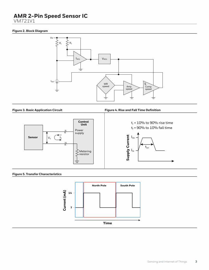
Figure 2. Block Diagram
Figure 3. Basic Application Circuit Figure 4. Rise and Fall Time Definition
Figure 5. Transfer Characteristics
VSSensor IS
Control Unit
Power supply
Meteringresistor
Supp
ly C
urre
nt
Time
ISh
ISl
ton
tr = 10% to 90% rise time tf = 90% to 10% fall time
IREG VREG
MRspeed Comp
speedAmp
speed
Vs
IREF
R1 R2
North Pole South Pole
Curr
ent (
mA) 14
7
Time

4 Sensing and Internet of Things
AMR 2-Pin Speed Sensor ICVM721V1
Figure 7. Dimensions and Product Marking (For reference only mm/[in])
Product Marking
Sensing Element Edge Distance
DMAX = 1,02 [0.04]
Product ID
Date code(three digits: year, week)
Work order number(one digit: 1-9)
Manufacturing code(one digit)
0,80[0.03]
1,6[0.62]
3,46[0.15]
3,6[0.14]
5,13[0.20]
3,93[0.15]
14,2[0.56]
2X 0,98 [0.038]
0,49[0.20]
1,48[0.06]
2X 0,4 [0.02]
0,73[0.029]
2X 0,38 [0.01]
2X 1,5 [0.06] 2,5
[0.10]
0,73[0.029]
Pin 1 Pin 2
Figure 6. Sensor IC Mounting Orientation
Radial Axial
Dimensions
PinoutPin
Number Symbol Function
1 VSsupplyvoltage
2 GND ground
Table 5. Order Guide
Catalog Listing Description
VM721V1Anisotropic Magnetoresistive (AMR) 2-Pin Speed Sensor Integrated Circuit, 2-pin SIP, bulk pack, 500 units/bag

For more informationHoneywell Sensing and Internet of Things services its customers through a worldwide network of sales offices and distributors. For application assistance, current specifications, pricing or the nearest Authorized Distributor, visit sensing.honeywell.com or call:Asia Pacific +65 6355-2828Europe +44 (0) 1698 481481USA/Canada +1-800-537-6945
Honeywell Sensing and Internet of Things 9680 Old Bailes Road
Fort Mill, SC 29707
www.honeywell.com
ADDITIONAL INFORMATIONThe following associated literature is available on the Honeywell
web site at sensing.honeywell.com:
• Installation instructions
• Application notes
• Technical notes
• CAD models
• Evaluation samples available from your local Honeywell
contact
• Function Safety Manual is available upon request. Contact
info.sc @honeywell.com
32336292-D-EN | D | 05/19© 2019 Honeywell International Inc.
Warranty/RemedyHoneywell warrants goods of its manufacture as being free of defective materials and faulty workmanship during the applicable warranty period. Honeywell’s standard product warranty applies unless agreed to otherwise by Honeywell in writing; please refer to your order acknowledgment or consult your local sales office for specific warranty details. If warranted goods are returned to Honeywell during the period of coverage, Honeywell will repair or replace, at its option, without charge those items that Honeywell, in its sole discretion, finds defective. The foregoing is buyer’s sole remedy and is in lieu of all other warranties, expressed or implied, including those of merchantability and fitness for a particular purpose. In no event shall Honeywell be liable for consequential, special, or indirect damages.
While Honeywell may provide application assistance personally, through our literature and the Honeywell web site, it is buyer’s sole responsibility to determine the suitability of the product in the application.
Specifications may change without notice. The information we supply is believed to be accurate and reliable as of this writing. However, Honeywell assumes no responsibility for its use.
WARNINGRISK TO LIFE OR PROPERTYNever use this product for an application involving serious risk to life or property without ensuring that the system as a whole has been designed to address the risks, and that this product is properly rated and installed for the intended use within the overall system.
Failure to comply with these instructions could result in death or serious injury.
WARNINGMISUSE OF DOCUMENTATION• The information presented in this datasheet is for
reference only. Do not use this document as a product installation guide.
• Complete installation, operation, and maintenance information is provided in the instructions supplied with each product.
Failure to comply with these instructions could result in death or serious injury.