hp303b digital pressure sensor - hoperf sensor 1.0.pdf · · 2016-12-29hp303b digital pressure...
TRANSCRIPT

Digital Barometric Pressure Sensor for Portable Devices
HP303B Digital Pressure Sensor
Product Description
The HP303B is a miniaturized Digital Barometric Air Pressure Sensor with a high accuracyand a low current consumption, capable of measuring both pressure and temperature.The pressure sensor element is based on a capacitive sensing principle whichguarantees high precision during temperature changes. The small package makes theHP303B ideal for mobile applications and wearable devices.The internal signal processor converts the output from the pressure and temperaturesensor elements to 24 bit results. Each unit is individually calibrated, the calibrationcoeicients calculated during this process are stored in the calibration registers. Thecoeicients are used in the application to convert the measurement results to highaccuracy pressure and temperature values.
The result FIFO can store up to 32 measurement results, allowing for a reduced host processor polling rate.Sensor measurements and calibration coeicients are available through the serial I2C or SPI interface. Themeasurement status is indicated by status bits or interrupts on the SDO pin.
Features• Operation range: Pressure: 300 –1200 hPa. Temperature: -40 – 85 °C.• Pressure sensor precision: ± 0.005 hPa (or ±0.05 m) (high precision mode).• Relative accuracy: ± 0.06 hPa (or ±0.5 m)• Absolute accuracy: ± 1 hPa (or ±8 m)• Temperature accuracy: ± 0.5°C.• Pressure temperature sensitivity: 0.5Pa/K• Measurement time: Typical: 27.6 ms for standard mode (16x). Minimum: 3.6 ms for low precision
mode.• Average current consumption: 1.7 µA for Pressure Measurement, 1.5uA for Temperature
measurement @1Hz sampling rate, Standby: 0.5 µA.• Supply voltage: VDDIO: 1.2 – 3.6 V, VDD: 1.7 – 3.6 V.• Operating modes: Command (manual), Background (automatic), and Standby.• Calibration: Individually calibrated with coeicients for measurement correction.• FIFO: Stores up to 32 pressure or temperature measurements.• Interface: I2C and SPI (both with optional interrupt)• Package dimensions: 8-pin LGA 3.6 mm x 3.8 mm x 1.2 mm.• Green Product (RoHS) Compliant
Typical Applications• Indoor Navigation (floor detection e.g. in shopping malls and parking garages)• Health and Sports (accurate elevation gain and vertical speed)• Outdoor Navigation (GPS start-up time and accuracy improvement, dead-reckoning e.g. in tunnels)• Weather Station('Micro-weather' and local forecasts)• HDD drivers, (leak rate detection in hard disk drives)• Drones (flight stability and height control)
Please read the Important Notice and Warnings at the end of this document V1.02016-09-05
HP303B - Digital Pressure Sensor
Table of contents
Product Description . . . . . . . . . . . . . . . . . . . . . . . . . . . . . . . . . . . . . . . . . . . . . . . . . . . . . . . . . . . . . . . . . . . . 1
Features . . . . . . . . . . . . . . . . . . . . . . . . . . . . . . . . . . . . . . . . . . . . . . . . . . . . . . . . . . . . . . . . . . . . . . . . . . . . . 1
Typical Applications . . . . . . . . . . . . . . . . . . . . . . . . . . . . . . . . . . . . . . . . . . . . . . . . . . . . . . . . . . . . . . . . . . . . 1
Table of contents . . . . . . . . . . . . . . . . . . . . . . . . . . . . . . . . . . . . . . . . . . . . . . . . . . . . . . . . . . . . . . . . . . . . . . . 2
1.1 Definitions . . . . . . . . . . . . . . . . . . . . . . . . . . . . . . . . . . . . . . . . . . . . . . . . . . . . . . . . . . . . . . . . . . . . . . . . . . . . . 4
2.1 Pin Configuration and Description . . . . . . . . . . . . . . . . . . . . . . . . . . . . . . . . . . . . . . . . . . . . . . . . . . . . . . . . .52.2 Block Diagram . . . . . . . . . . . . . . . . . . . . . . . . . . . . . . . . . . . . . . . . . . . . . . . . . . . . . . . . . . . . . . . . . . . . . . . . . 6
3.1 Operating Range . . . . . . . . . . . . . . . . . . . . . . . . . . . .. . . . . . . . . . . . . . . . . . . . . . . . . . . . . . . . . . . . . . . . . . . . 63.2 Absolute Maximum Ratings . . . . . . . . . . . . . . . . . . . . . . . . . . . . . . . . . . . . . . . . . . . . . . . . . . . . . . . . . . . . . . .73.3 Current Consumption . . . . . . . . . . . . . . . . . . . . . . . . . . . . . . . . . . . . . . . . . . . . . . . . . . . . . . . . . . . . . . . . . . . . 73.4 Temperature Transfer Function . . . . . . . . . . . . . . . . . . . . . . . . . . . . . . . . . . . . . . . . . . . . . . . . . . . . . . . . . . . 83.5 Pressure Transfer Function . . . . . . . . . . . . . . . . . . . . . . . . . . . . . . . . . . . . . . . . . . . . . . . . . . . . . . . . . . . . . . . 93.6 Timing Characteristics . . . . . . . . . . . . . . . . . . . . . . . . . . . . . . . . . . . . . . . . . . . . . . . . . . . . . . . . . . . . . . . . . . 10
4.1 Operating Modes . . . . . . . . . . . . . . . . . . . . . . . . . . . . . . . . . . . . . . . . . . . . . . . . . . . . . . . . . . . . . . . . . . . . . . 104.2 Mode transition diagram . . . . . . . . . . . . . . . . . . . . . . . . . . . . . . . . . . . . . . . . . . . . . . . . . . . . . . . . . . . . . . . 104.3 Start-up sequence . . . . . . . . . . . . . . . . . . . . . . . . . . . . . . . . . . . . . . . . . . . . . . . . . . . . . . . . . . . . . . . . . . . . . 114.4 Measurement Precision and Rate . . . . . . . . . . . . . . . . . . . . . . . . . . . . . . . . . . . . . . . . . . . . . . . . . . . . . . . . 114.5 Sensor Interface . . . . . . . . . . . . . . . . . . . . . . . . . . . . . . . . . . . . . . . . . . . . . . . . . . . . . . . . . . . . . . . . . . . . . . .124.6 Interrupt . . . . . . . . . . . . . . . . . . . . . . . . . . . . . . . . . . . . . . . . . . . . . . . . . . . . . . . . . . . . . . . . . . . . . . . . . . . . . 124.7 Result Register Operation . . . . . . . . . . . . . . . . . . . . . . . . . . . . . . . . . . . . . . . . . . . . . . . . . . . . . . . . . . . . . . 134.8 FIFO Operation . . . . . . . . . . . . . . . . . . . . . . . . . . . . . . . . . . . . . . . . . . . . . . . . . . . . . . . . . . . . . . . . . . . . . . . .134.9 Calibration and Measurement Compensation . . . . . . . . . . . . . . . . . . . . . . . . . . . . . . . . . . . . . . . . . . . . . 134.9.1 How to Calculate Compensated Pressure Values . . . . . . . . . . . . . . . . . . . . . . . . . . . . . . . . . . . . . . . . . 144.9.2 How to Calculate Compensated Temperature Values . . . . . . . . . . . . . . . . . . . . . . . . . . . . . . . . . . . . . 144.9.3 Compensation Scale Factors . . . . . . . . . . . . . . . . . . . . . . . . . . . . . . . . . . . . . . . . . . . . . . . . . . . . . . . . . . . 154.9.4 Pressure and Temperature calculation flow . . . . . . . . . . . . . . . . . . . . . . . . . . . . . . . . . . . . . . . . . . . . . 15
5.1 Measurement Settings and Use Case Examples . . . . . . . . . . . . . . . . . . . . . . . . . . . . . . . . . . . . . . . . . . . . 175.2 Application Circuit Example . . . . . . . . . . . . . . . . . . . . . . . . . . . . . . . . . . . . . . . . . . . . . . . . . . . . . . . . . . . . . 185.3 IIR filtering . . . . . . . . . . . . . . . . . . . . . . . . . . . . . . . . . . . . . . . . . . . . . . . . . . . . . . . . . . . . . . . . . . . . . . . . . . . .19
6.1 I2C Interface . . . . . . . . . . . . . . . . . . . . . . . . . . . . . . . . . . . . . . . . . . . . . . . . . . . . . . . . . . . . . . . . . . . . . . . . . . . 206.2 SPI Interface . . . . . . . . . . . . . . . . . . . . . . . . . . . . . . . . . . . . . . . . . . . . . . . . . . . . . . . . . . . . . . . . . . . . . . . . . . . 20
HP303B - Digital Pressure SensorDigital Barometric Pressure Sensor for Portable Devices
Table of contents
2 V1.02016-09-05
1 Definitions, acronyms and abbreviations . . . . . . . . . . . . . . . . . . . . . . . . . . . . . . . . . . . . . . . . . . . . . . . .4
2 Pin Configuration and Block Diagram . . . . . . . . . . . . . . . . . . . . . . . . . . . . . . . . . . . . . . . . . . .. . . . . . . . .5
3 Specifications . . . . . . . . . . . . . . . . . . . . . . . . . . . . . . . . . . . . . . . . . .. . . . . . . . . . . . . . . . . . . . . . . . . . . . . . . . . .6
4 Functional Description . . . . . . . . . . . . . . . . . . . . . . . . . . . . . . . . . . . . . . . . . . . . . . . . . . . . . . . . . . . . . . . .10. .
5 Applications . . .. . .. . . . . . . . . . . . . . . . . . . . . . . . . . . . . . . . . . . . . . . . . . . . . . . . . . . . . . . . . . . . . . . . . . . . . . . .17
6 Digital interfaces . . . . . . . . . . . . . . . . . . . . . . . . . . . . . . . . . . . . . . . . . . . . . . . . . . . . . . . . . . . . . . . . . . . .19. . .. . .

6.3 Interface parameters specification . . . . . . . . . . . . . . . . . . . . . . . . . . . . . . . . . . . . . . . . . . . . . . . . . . . . . . . 216.3.1 General interface parameters . . . . . . . . . . . . . . . . . . . . . . . . . . . . . . . . . . . . . . . . . . . . . . . . . . . . . . . . . . 226.3.1.1 I2C timings . . . . . . . . . . . . . . . . . . . . . . . . . . . . . . . . . . . . . . . . . . . . . . . . . . . . . . . . . . . . . . . . . . . . . . . . 226.3.1.2 SPI timings . . . . . . . . . . . . . . . . . . . . . . . . . . . . . . . . . . . . . . . . . . . . . . . . . . . . . . . . . . . . . . . . . . . . . . . . 24
8.1 Pressure Data (PRS_Bn) . . . . . . . . . . . . . . . . . . . . . . . . . . . . . . . . . . . . . . . . . . . . . . . . . . . . . . . . . . . . . . . . . 258.1.1 PRS_B2 . . . . . . . . . . . . . . . . . . . . . . . . . . . . . . . . . . . . . . . . . . . . . . . . . . . . . . . . . . . . . . . . . . . . . . . . . . . . . . 268.1.2 PRS_B1 . . . . . . . . . . . . . . . . . . . . . . . . . . . . . . . . . . . . . . . . . . . . . . . . . . . . . . . . . . . . . . . . . . . . . . . . . . . . . . 268.1.3 PRS_B0 . . . . . . . . . . . . . . . . . . . . . . . . . . . . . . . . . . . . . . . . . . . . . . . . . . . . . . . . . . . . . . . . . . . . . . . . . . . . . . 278.2 Temperature Data (TMP_Tn) . . . . . . . . . . . . . . . . . . . . . . . . . . . . . . . . . . . . . . . . . . . . . . . . . . . . . . . . . . . . . 278.2.1 TMP_B2 . . . . . . . . . . . . . . . . . . . . . . . . . . . . . . . . . . . . . . . . . . . . . . . . . . . . . . . . . . . . . . . . . . . . . . . . . . . . . 278.2.2 TMP_B1 . . . . . . . . . . . . . . . . . . . . . . . . . . . . . . . . . . . . . . . . . . . . . . . . . . . . . . . . . . . . . . . . . . . . . . . . . . . . 288.2.3 TMP_B0 . . . . . . . . . . . . . . . . . . . . . . . . . . . . . . . . . . . . . . . . . . . . . . . . . . . . . . . . . . . .. . . . . . . . . . . . . . . . . 288.3 Pressure Configuration (PRS_CFG) . . . . . . . . . . . . . . . . . . . . . . . . . . . . . . . . . . . . . . . . . . . . . . . . . . . . . . . 298.4 Temperature Configuration(TMP_CFG) . . . . . . . . . . . . . . . . . . . . . . . . . . . . . . . . . . . . . . . . . . . . . . . . . . . 318.5 Sensor Operating Mode and Status (MEAS_CFG) . . . . . . . . . . . . . . . . . . . . . . . . . . . . . . . . . . . . . . . . . . . 328.6 Interrupt and FIFO configuration (CFG_REG) . . . . . . . . . . . . . . . . . . . . . . . . . . . . . . . . . . . . . . . . . . . . . . 338.7 Interrupt Status (INT_STS) . . . . . . . . . . . . . . . . . . . . . . . . . . . . . . . . . . . . .. . . . . . . . . . . . . . . . . . . . . . . . . .348.8 FIFO Status (FIFO_STS) . . . . . . . . . . . . . . . . . . . . . . . . . . . . . . . . . . . . . . .. . . . . . . . . . . . . . . . . . . . . . . . . . .358.9 o Reset and FIFO flush (RESET) . . . . . . . . . . . . . . . . . . . . . . . . . . . . . . . . . . . . . . . . . . . . . . . . . . . . . . . .36 . . . 8.10 Product and Revision ID (ID) . . . . . . . . . . . . . . . . . . . . . . . . . . . . . . . . . . . . . . . . . . . . . . . .. . . . . . . . . . . . 36
(COEF) . . . . . . . . . . . . . . . . . . . . . . . . . . . . . . . . . . . . . . . . . . . . . . . . . . . . . . . . . . 378.12 Coeicient Source . . . . . . . . . . . . . . . . . . . . . . . . . . . . . . . . . . . . . . . . . . . . . . . . . . . . . . . . . . . . . . . . . . . . . . 38
Digital Barometric Pressure Sensor for Portable Devices
Table of contents
3 V1.02016-09-05
HP303B - Digital Pressure Sensor
8 Register description . . . . . . . . . . . . . . . . . . . . . . . . . . . . . . . . . . . . . . . . . . . . . . . . . . . . . . . . . . . . .. . . . . . . .25
7 Register Map . . . . . . . . . . . . . . . . . . . . . . . . . . . . . . . . . . . . . . . . . . . . . . . . . . . . . . . . . . . . . . . . . . . . . . . .25
9 Package Dimensions . . . . . . . . . . . . . . . . . . . . . . . . . . . . . . . . . . . . . . . . . . . . . . . . . . . . . . . . . . . . . . . .38

1 Definitions, acronyms and abbreviations
1.1 DefinitionsAn explanation of terms and definitions used in this datasheet.
Table 1
Term Definition/explanationAbsolute accuracy The absolute measurement accuracy over the entire measurement
range.
Digital bit depth The total bit depth used for conversion of the sensor input to thedigital output. Measured in bits.
Digital resolution The pressure value represented by the LSB change in output. Thisvalue should be much smaller than the sensor noise.
Full Scale Range (FSR) The peak-to-peak measurement range of the sensor.
LSB Least Significant Bit
Measurement time The time required to acquire one sensor output result. This valuedetermines the maximum measurement rate.
MSB Most Significant Bit
Non-linearity The deviation of measured output from the best-fit straight line,relative to 1000 hPa and 25 °C.
Output compensation The process of applying an algorithm to the sensor output to improvethe absolute accuracy of the sensor across temperature and tominimize unit to unit output variation. This algorithm makes use ofboth the temperature sensor readings and the individual calibrationcoeicients
Precision (noise) The smallest measurable change, expressed as rms, aer sensoroversampling.
Pressure temperature coeicient The pressure measurement deviation, aer compensation, fromexpected measurement value due to temperature change from 25 °C.Measured in Pa/K.
Sensor calibration The process, during the production test, where the sensor'smeasurement results are compared against reference values, and a setof calibration coeicients are calculated from the deviation. Thecoeicients are stored in the sensor's memory and are used in theoutput compensation.
Sensor oversampling rate (OSR) Specifies the number of sensor measurements used internally togenerate one sensor output result.
Digital Barometric Pressure Sensor for Portable Devices
Definitions, acronyms and abbreviations
4 V1.02016-09-05
HP303B - Digital Pressure Sensor

2 Pin Configuration and Block Diagram
2.1 Pin Configuration and Description
Figure 1 Pin configuration (top view, figure not to scale)
Table 2 Pin description
Pin Name SPI 3-wire SPI 3-wire withinterrupt
I2C
1
2
3
4
5
6
Digital supply voltage for digital blocks and I/O interface
7
Digital Barometric Pressure Sensor for Portable Devices
Pin Configuration and Block Diagram
5 V1.02016-09-05
HP303B - Digital Pressure Sensor
1
2
3
4
8
7
6
5
1
2
3
4
8
7
6
5
VENT HOLE
VDDIO
GND
VDD
NCSCL
SDA
CSB
SDO
VDDIO
GND
VDD
NC
Analog supply voltage
Serial data in/out
Chip select,active low Not used - open
NO Connect InterruptLeast significantbit in the device address.
NO Connect
GND
SCL Clock
SDA Serial data in/out Serial data in/out
CSB Chip select,active low
8 SDO

2.2 Block Diagram
Figure 2
3 Specifications
3.1 Operating RangeThe following operating conditions must not be exceeded in order to ensure correct operation of the device. Allparameters specified in the following sections refer to these operating conditions, unless noted otherwise.
Table 3 Operating Range
Parameter Symbol Values Unit Note / Test ConditionMin. Typ. Max.
Pressure Pa 300 1200 hPa
Temperature Ta -40 85 °C
Supply voltage VDD 1.7 3.6 V
Supply voltage IO VDDIO 1.2 3.6 V
Supply voltage ramp-up time tvddup 0.001 5 ms Time for supply voltageto reach 90% of finalvalue.
Solder dri 1) 0.8 hPa Minimum solder height50um.
Long term stability ± 1 hPa Depending onenvironmentalconditions.
Digital Barometric Pressure Sensor for Portable Devices
Specifications
6 V1.02016-09-05
HP303B - Digital Pressure Sensor

3.2 Absolute Maximum RatingsMaximum ratings are absolute ratings. Exceeding any one of these values may cause irreversible damage to theintegrated circuit.
Attention: Stresses above the values listed as "Absolute Maximum Ratings" may cause permanent damageto the devices. Exposure to absolute maximum rating conditions for extended periods may tdevice reliability.
Table 4 Absolute Maximum Ratings
Parameter Symbol Values Unit Note / TestConditionMin. Typ. Max.
VDD and VDDIO VDDxx_max 4 V
Voltage on any pin Vmax 4 V
Storage temperature Ts -40 125 °C
Pressure Pmax 10,000 hPa
ESD VESD_HBM -2 2 KV HBM (JS001)
3.3 Current ConsumptionTest conditions (unless otherwise specified in the table): VDD= 1.8V and VDDIO=1.8V. Typ. values (PA=1000hPa andTA=25°C). Max./Min. values (PA= 950-1050hPa and TA=0...+65°C).
Table 5 Current Consumption
Parameter Symbol Values Unit Note / Test ConditionMin. Typ. Max.
Peak Current Consumption Ipeak 345 µA during Pressuremeasurement
280 µA during Temperaturemeasurement
Standby Current Consumption Istb 0.5 µA
Current Consumption.( 1 measurement per second.)
I1Hz 2.1 µA Low precision
11 Standard precision
38 High precision
Note: The current consumption depends on both pressure measurement precision and rate. Please refer to the Pressure Configuration (PRS_CFG) register description for an overview of the current consumption in derentcombinations of measurement precision and rate.
Digital Barometric Pressure Sensor for Portable Devices
Specifications
7 V1.02016-09-05
HP303B - Digital Pressure Sensor

3.4 Temperature Transfer FunctionTest conditions (unless otherwise specified in the table): VDD= 1.8V and VDDIO=1.8V. Typ. values (PA=1000hPa andTA=25°C). Max./Min. values (PA= 950-1050hPa and TA=0...+65°C).
Table 6 Temperature Transfer Function
Parameter Symbol Values Unit Note / Test ConditionMin. Typ. Max.
Temperature accuracy At +/-0.5 °C
Temperature data resolution At_res 0.01 °C
Temperature measurement rate f 1 128 Hz
Digital Barometric Pressure Sensor for Portable Devices
Specifications
8 V1.02016-09-05
HP303B - Digital Pressure Sensor

3.5 Pressure Transfer FunctionTest conditions (unless otherwise specified in the table): VDD= 1.8V and VDDIO=1.8V. Typ. values (PA=1000hPa andTA=25°C).
Table 7 Pressure Transfer Function
Parameter Symbol Values Unit Note / Test ConditionMin. Typ. Max.
Absolute pressure accuracy Ap_abs +/-10 Pa Aer one point calibration
+/-100 Pa PA=300-1200hPaTA=0...+65°CExcluding solder eects
Relative pressure accuracy Ap_rel +/-6 Pa Any Δ1hPa in the rangePA=800-1200hPaAny constant temperaturein the range TA=20...+60°C
Pressure precision Ap_prc 5.0 PaRMS Low Power
1.2 Standard
0.5 High Precision
Note: Pressure precision is measured as the average standard deviation. Please refer to the PressureConfiguration (PRS_CFG) register description for all precision mode options.
Power supply rejection Ap_psr 0.063 PaRMS Measured with 217Hzsquare wave and broadband noise, 100mVpp
Pressure temperature sensitivityof calibrated measurements
Ap_tmp 0.5 Pa/K 1000hPa, 25...+65°C.
Pressure data resolution Ap_res 0.06 PaRMS
Pressure measurement rate f 1 128 Hz
Pressure measurement time t 5.2 ms Low Power
27.6 Standard
105 High Precision
Note: The pressure measurement time (and thus the maximum rate) depends on the pressuremeasurement precision. Please refer to the register descriptionPressure Configuration (PRS_CFG)for an overview of the possible combinations of measurement precision and rate.
Digital Barometric Pressure Sensor for Portable Devices
Specifications
9 V1.02016-09-05
HP303B - Digital Pressure Sensor
3.6 Timing Characteristics
Table 8 Timing Characteristics
Parameter Symbol Values Unit Note / Test ConditionMin. Typ. Max.
Start-up timing
Time to sensor ready TSensor_rdy 12 ms The SENSOR_RDY bit in theMeasurement Configurationregister will be set when thesensor is ready.
Time to coeicients areavailable.
TCoef_rdy 40 ms The COEF_RDY bit in theMeasurement Configurationregister will be set when thecoeicients can be read out.
Note: Start-up timing is measured from VDD > 1.2V & VDDIO > 0.6V or o Reset.
I2C Clock. fI2C 3.4 MHz
SPI Clock fSPI 10 MHz
4 Functional Description
4.1 Operating ModesThe supports 3 dierentHP303B modes of operation: Standby, Command, and Background mode.• Standby Mode
power on or reset. No measurements are performed. are accessible.
• Command Mode- One temperature or pressure measurement is performed according to the selected precision.- The sensor will return to Standby Mode when the measurement is finished, and the measurement result
will be available in the data registers.• Background Mode
- Pressure and/or temperature measurements are performed continuously according to the selectedmeasurement precision and rate. The temperature measurement is performed immediately aer thepressure measurement.
- The FIFO can be used to store 32 measurement results and minimize the number of times the sensor mustbe accessed to read out the results.
Note: Operation mode and measurement type are set in the Sensor Operating Mode and Status(MEAS_CFG) register.
4.2 Mode transition diagramThe mode transition diagram is shown below.
Digital Barometric Pressure Sensor for Portable Devices
Functional Description
10 V1.02016-09-05
HP303B - Digital Pressure Sensor

Figure 3 Mode transition diagram
4.3 Start-up sequenceThe start-up sequence is shown below. This diagram shows when the registers are accessible for read and/orwrite and also when the Pressure/Temperature measurements can start.
Figure 4 Start-up sequence
4.4 Measurement Precision and RateDierent applications require dierent measurement precision and measurement rates. Some applications,such as weather stations, require lower precision and measurement rates than for instance indoor navigationand sports applications.
When the is in Background Mode, the measurement precision and rate can be configured to match theHP303Brequirements of the application. This reduces current consumption of the sensor and the system.
Digital Barometric Pressure Sensor for Portable Devices
Functional Description
11 V1.02016-09-05
HP303B - Digital Pressure Sensor
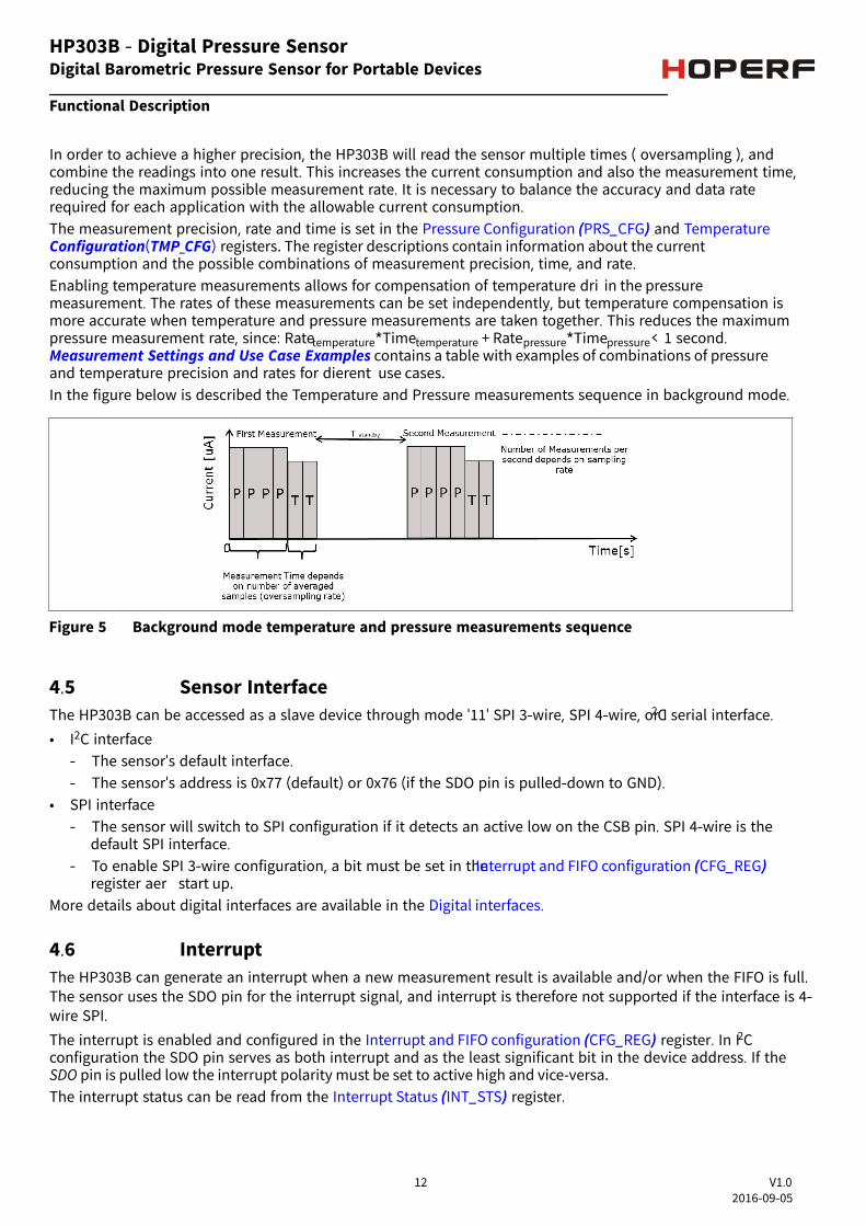
In order to achieve a higher precision, the will read the sensor multiple times ( oversampling ), andHP303Bcombine the readings into one result. This increases the current consumption and also the measurement time,reducing the maximum possible measurement rate. It is necessary to balance the accuracy and data raterequired for each application with the allowable current consumption.The measurement precision, rate and time is set in the and Pressure Configuration (PRS_CFG) TemperatureConfiguration(TMP_CFG) registers. The register descriptions contain information about the currentconsumption and the possible combinations of measurement precision, time, and rate.Enabling temperature measurements allows for compensation of temperature dri in the pressuremeasurement. The rates of these measurements can be set independently, but temperature compensation ismore accurate when temperature and pressure measurements are taken together. This reduces the maximumpressure measurement rate, since: Ratetemperature*Timetemperature + Ratepressure*Timepressure< 1 second. Measurement Settings and Use Case Examples contains a table with examples of combinations of pressureand temperature precision and rates for dierent use cases.In the figure below is described the Temperature and Pressure measurements sequence in background mode.
Figure 5 Background mode temperature and pressure measurements sequence
4.5 Sensor InterfaceThe can be accessed as a slave device through mode '11' SPI 3-wire, SPI 4-wire, or IHP303B 2C serial interface.
• I2C interface- The sensor's default interface.- The sensor's address is 0x77 (default) or 0x76 (if the SDO pin is pulled-down to GND).
• SPI interface- The sensor will switch to SPI configuration if it detects an active low on the CSB pin. SPI 4-wire is the
default SPI interface.- To enable SPI 3-wire configuration, a bit must be set in the Interrupt and FIFO configuration (CFG_REG)
register aer start up.More details about digital interfaces are available in the .Digital interfaces
4.6 InterruptThe can generate an interrupt when a new measurement result is available and/or when the FIFO is full.HP303BThe sensor uses the SDO pin for the interrupt signal, and interrupt is therefore not supported if the interface is 4-wire SPI.The interrupt is enabled and configured in the register. In IInterrupt and FIFO configuration (CFG_REG) 2Cconfiguration the SDO pin serves as both interrupt and as the least significant bit in the device address. If theSDO pin is pulled low the interrupt polarity must be set to active high and vice-versa.The interrupt status can be read from the register.Interrupt Status (INT_STS)
Digital Barometric Pressure Sensor for Portable Devices
Functional Description
12 V1.02016-09-05
HP303B - Digital Pressure Sensor

4.7 Result Register OperationAer starting the measurements, the latest pressure and temperature raw data will be available in theirrespective result registers. Temperature measurement can be skipped. The temperature measurements can bedisabled if there is a requirement to measure pressure rapidly, but it will make accurate temperature dricompensation impossible.
All measurement data can be read in a single command using auto-increment read. When FIFO is disabled,reading the result register will not aect the register value, it will only be updated when a new measurement iscompleted. When FIFO is enabled, the pressure result register will update to the next value in the FIFO aer eachread. When all of the FIFO values have been read, the result register will be set to 0x800000.
4.8 FIFO OperationThe HP303B FIFO can store the last 32 measurements of pressure or temperature. This reduces the overallsystem power consumption as the host processor does not need to continuously poll data from the sensor butcan go into standby mode for longer periods of time.
The FIFO can store any combination of pressure and temperature results, according to the background modemeasurement rate settings. The pressure rate can for instance be set 4 times higher than the temperature rateand thus only every fih result will be a temperature result. The measurement type can be seen in the resultdata. The sensor will set the least significant bit to:• '1' if the result is a pressure measurement.• '0' if it is a temperature measurement.
- The sensor uses 24 bits to store the measurement result. Because this is more bits than is needed to coverthe full dynamic range of the pressure sensor, using the least significant bit to label the measurementtype will not aect the precision of the result.
The FIFO can be enabled in the Interrupt and FIFO configuration register. The data from the FIFO is read outfrom the Pressure Data (PRS_Bn) registers regardless of whether the next result in the FIFO is a temperature or apressure measurement.When a measurement has been read out, the FIFO will auto increment and place the next result in the dataregister. A flag will be set in the FIFO Status register when the FIFO is empty and all following reads will return0x800000.If the FIFO is full, the FIFO_FULL bit in the FIFO Status (FIFO_STS)will be set. If the INT_FIFO bit in the Interruptand FIFO configuration register ( CFG_REG) is set, an interrupt will also be generated when the FIFO is full.The FIFO will stop recording measurements results when it is full.
4.9 Calibration and Measurement CompensationThe is a calibrated sensor and contains calibration coeicientsHP303B These are used in the application (forinstance by the host processor) to compensate the measurement results for sensor non-linearities.
The sections that follow describe how to calculate the compensated results and convert them into Pa and °Cvalues.
Digital Barometric Pressure Sensor for Portable Devices
Functional Description
13 V1.02016-09-05
HP303B - Digital Pressure Sensor

4.9.1 How to Calculate Compensated Pressure Values
Steps
1. Read the pressure calibration coeicients (c00, c10, c20, c30, c01, c11, and c21) from the CalibrationCoeicient register.
Note: The coecents read from the coecent register are 2's complement numbers.
2. Choose scaling factors kT (for temperature) and kP (for pressure) based on the chosen precision rate. Thescaling factors are listed in .Table 9
3. Read the pressure and temperature result from the registers or FIFO.
Note: The measurements read from the result registers (or FIFO) are 24 bit 2´s complement numbers.Depending on the chosen measurement rates, the temperature may not have been measuredsince the last pressure measurement.
4. Calculate scaled measurement results.
Traw_sc = Traw/kTPraw_sc = Praw/kP
5. Calculate compensated measurement results.
Pcomp(Pa) = c00 + P raw_sc *(c10 + P raw_sc *(c20+ Praw_sc *c30)) + Traw_sc *c01 +
Traw_sc *Praw_sc *(c11+Praw_sc *c21)
4.9.2 How to Calculate Compensated Temperature Values
Steps
1. Read the temperature calibration coeicients ( c0 and c1 ) from the Calibration onts (COEF) register.
Note: The coecents read from the coecent register are 12 bit 2´s complement numbers.
2. Choose scaling factor kT (for temperature) based on the chosen precision rate. The scaling factors are listedin .Table 9
3. Read the temperature result from the temperature register or FIFO.
Note: The temperature measurements read from the temperature result register (or FIFO) are 24 bit 2´scomplement numbers.
4. Calculate scaled measurement results.
Traw_sc = Traw/kT
5. Calculate compensated measurement results.
Digital Barometric Pressure Sensor for Portable Devices
Functional Description
14 V1.02016-09-05
HP303B - Digital Pressure Sensor

Tcomp (°C) = c0*0.5 + c1*Traw_sc
4.9.3 Compensation Scale Factors
Table 9 Compensation Scale Factors
Oversampling Rate Scale Factor (kP or kT) Result shi ( bit 2and 3 address0x09)
1 (single) 524288 0
2 times (Low Power) 1572864 0
4 times 3670016 0
8 times 7864320 0
16 times (Standard) 253952 enable pressure or temperatureshi
32 times 516096 enable pressure or temperatureshi
64 times (High Precision) 1040384 enable pressure or temperatureshi
128 times 2088960 enable pressure or temperatureshi
4.9.4 Pressure and Temperature calculation flowThe flow chart below describes the Pressure and Temperature calculate
Figure 6 Pressure and temperature calculation flow
Digital Barometric Pressure Sensor for Portable Devices
Functional Description
15 V1.02016-09-05
HP303B - Digital Pressure Sensor
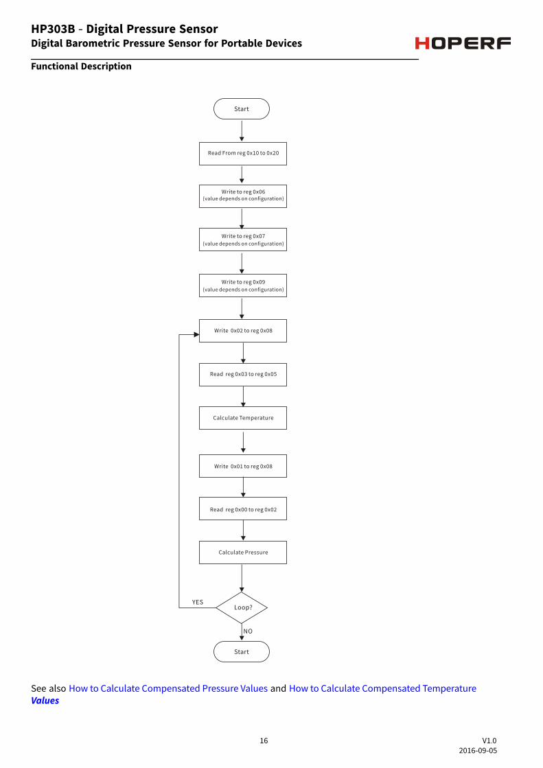
See also and How to Calculate Compensated Pressure Values How to Calculate Compensated TemperatureValues
Digital Barometric Pressure Sensor for Portable Devices
Functional Description
HP303B - Digital Pressure Sensor
16 V1.02016-09-05

5 Applications
5.1 Measurement Settings and Use Case Examples
Table 10 Measurement Settings and Use Case Examples (TBD)
Use Case Performance Pressure RegisterConfigurationAddress: 0x06
TemperatureRegisterConfigurationAddress: 0x07
Other
Weather Station (Low power) 5 Pa precision.1 pr sec.3 uA
0x01 0x80 Startbackgroundmeasurements(addr 0x08)
Indoor navigation (Standardprecision, background mode)
10 cm precision.2 pr sec.22 uA
0x14 0x90 Enable P shi(addr 0x09)Startbackgroundmeasurements(addr 0x08)
Sports (High precision, highrate, background mode)
5 cm precision4 pr sec.200 uA
0x26 0xA0 Enable P shi(addr 0x09)Startbackgroundmeasurements(addr 0x08)
Digital Barometric Pressure Sensor for Portable Devices
Applications
17 V1.02016-09-05
HP303B - Digital Pressure Sensor

5.2 Application Circuit ExampleThe examples application circuit uses the I2C and SPI serial interface. The SDO pin can be used for interrupt orto set least significant bit of the device address. The HP303B analog core supply voltage is internally regulated,guaranteeing robustness to external VDD supply variations within the specified range. The simplest voltagesupply solution is to connect VDD and VDDIO to 1.8V supply and add a suitable decoupling capacitor to reduceVDD ripple below 50mVpp.
Figure 7 Application Circuit Example using the I2C serial interface.
Figure 8 Application Circuit Example using the SPI 4-wires serial interface
Figure 9 Application Circuit Example using the SPI 3-wire serial interface
Digital Barometric Pressure Sensor for Portable Devices
Applications
18 V1.02016-09-05
HP303B - Digital Pressure Sensor
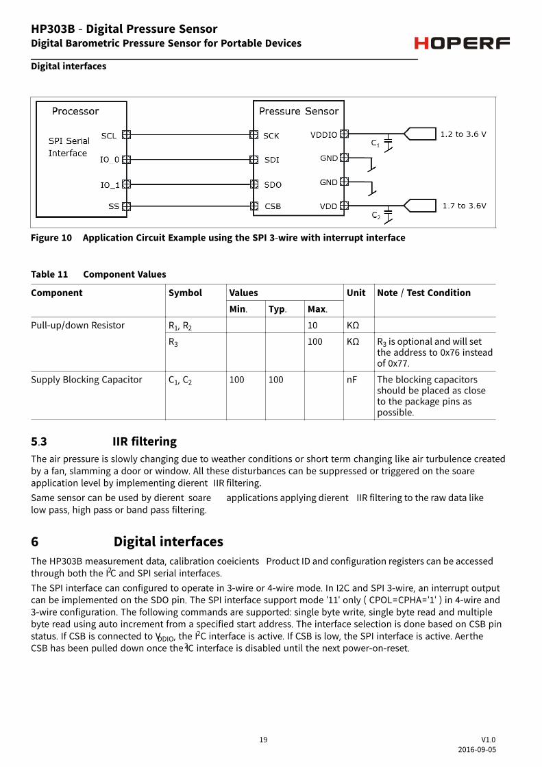
Figure 10 Application Circuit Example using the SPI 3-wire with interrupt interface
Table 11 Component Values
Component Symbol Values Unit Note / Test ConditionMin. Typ. Max.
Pull-up/down Resistor R1, R2 10 KΩ
R3 100 KΩ R3 is optional and will setthe address to 0x76 insteadof 0x77.
Supply Blocking Capacitor C1, C2 100 100 nF The blocking capacitorsshould be placed as closeto the package pins aspossible.
5.3 IIR filteringThe air pressure is slowly changing due to weather conditions or short term changing like air turbulence createdby a fan, slamming a door or window. All these disturbances can be suppressed or triggered on the soareapplication level by implementing dierent IIR filtering.Same sensor can be used by dierent soare applications applying dierent IIR filtering to the raw data likelow pass, high pass or band pass filtering.
6 Digital interfacesThe HP303B measurement data, calibration coeicients Product ID and configuration registers can be accessedthrough both the I2C and SPI serial interfaces.
The SPI interface can configured to operate in 3-wire or 4-wire mode. In I2C and SPI 3-wire, an interrupt outputcan be implemented on the SDO pin. The SPI interface support mode '11' only ( CPOL=CPHA='1' ) in 4-wire and3-wire configuration. The following commands are supported: single byte write, single byte read and multiplebyte read using auto increment from a specified start address. The interface selection is done based on CSB pinstatus. If CSB is connected to VDDIO, the I2C interface is active. If CSB is low, the SPI interface is active. Aer theCSB has been pulled down once the I2C interface is disabled until the next power-on-reset.
Digital Barometric Pressure Sensor for Portable Devices
Digital interfaces
19 V1.02016-09-05
HP303B - Digital Pressure Sensor

6.1 I2C InterfaceThe I2C slave interface is compatible with Philips I2C Specification version 2.1. The I2C interface supportsstandard, fast and high speed mode.
The sensor's address is 0x77 (if SDO pin is e floating or pulled-up to VDDIO) or 0x76 (if the SDO pin is pulled-down to GND). The I2C interface uses the pins described in Table 2The basic timing is shown in the diagram below:
Figure 11 I2C timing diagram
In one access, without stop, incremental read (address is auto increment) and auto-incremental write issupported. The read and write access is described below:
Figure 12 I2C write and read commands
6.2 SPI InterfaceThe SPI interface is compatible with SPI mode '11' ( CPOL = CPHA = '1'. The SPI interface has two modes: 4-wireand 3-wire.
The protocol is the same for both. The 3-wire mode is selected by setting '1' to the register Interrupt and FIFOconfiguration (CFG_REG)
The SPI interface uses the pins like in the Refere to for connectionsTable 2 Application Circuit Exampleinstructions. The SPI protocol is shown in the diagram below:
Figure 13 SPI protocol, 4-wire without interrupt
Digital Barometric Pressure Sensor for Portable Devices
Digital interfaces
20 V1.02016-09-05
HP303B - Digital Pressure Sensor
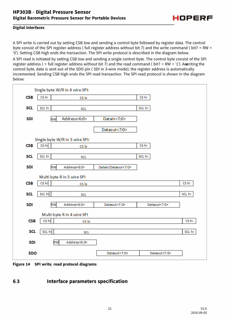
A SPI write is carried out by setting CSB low and sending a control byte followed by register data. The controlbyte consist of the SPI register address ( full register address without bit 7) and the write command ( bit7 = RW ='0'). Setting CSB high ends the transaction. The SPI write protocol is described in the diagram below.
A SPI read is initiated by setting CSB low and sending a single control byte. The control byte consist of the SPIregister address ( = full register address without bit 7) and the read command ( bit7 = RW = '1'). Aer writing thecontrol byte, data is sent out of the SDO pin ( SDI in 3-wire mode); the register address is automaticallyincremented. Sending CSB high ends the SPI read transaction. The SPI read protocol is shown in the diagrambelow:
Figure 14 SPI write, read protocol diagrams
6.3 Interface parameters specification
Digital Barometric Pressure Sensor for Portable Devices
Digital interfaces
21 V1.02016-09-05
HP303B - Digital Pressure Sensor

6.3.1 General interface parametersThe general interface parameters are given in the table below:
Table 12 Interface parameters
Parameter Symbol Values Unit Note or TestConditionMin. Typ. Max.
Input voltage for low logiclevel at input pins
Vlow_in 0.3 *VDDIO
V VDDIO=1.2V to 3.6V
Input voltage for high logiclevel at input pins
Vhigh_in 0.7 *VDDIO
V VDDIO=1.2V to 3.6V
Output - low level for I2C Vlow_SDI 0.1 *VDDIO
V VDDIO=1.8V,iol=2mA
Output voltage for low levelat pin SDI for I2C
Vlow_SDI_1.2 0.2*VDDIO
V VDDIO=1.20V,iol=1.3mA
Output voltage for high levelat pins SDO, SDI
Vhigh_out 0.8 *VDDIO
V VDDIO=1.8V,iol=1mA (SDO,SDI)
Output voltage for high levelat pins SDO, SDI
Vhigh_out_1.2 0.6 *VDDIO
V VDDIO=1.2V,iol=1mA (SDO,SDI)
Pull-up resistor Rpull 60 120 180 kohm Internal pull-upresistance to VDDIO
I2C bus load capacitor Cb 400 pF On SDI and SCK
6.3.1.1 I2C timingsThe I2C timing is shown in the diagram below and corresponding values are given in the table below. Thenaming refers to I2C Specification version 2.1, the abbreviations used "S&F mode" = standard and fast mode,"HS mode" = high speed mode, Cb = bus capacitance on SDA line.
Digital Barometric Pressure Sensor for Portable Devices
Digital interfaces
22 V1.02016-09-05
HP303B - Digital Pressure Sensor

Figure 15 I2C timing diagram
Table 13 I2C timings
Parameter Symbol Values Unit Note or TestConditionMin. Typ. Max.
Data setup time on SDI pin tSetup 20 ns S&F mode
5 ns HS mode
Data hold time on SDI pin tHold 0 ns S&F&HSmode,
Duty Cycle DC 70 % S&F mode,
55 % HS mode,
Digital Barometric Pressure Sensor for Portable Devices
Digital interfaces
23 V1.02016-09-05
HP303B - Digital Pressure Sensor

6.3.1.2 SPI timingsThe SPI timing diagram is shown in the figure below and the corresponding values are given in the table below.All timings apply both to 4-wire and 3-wire SPI.
Figure 16 SPI timing diagram
Table 14 SPI timings
Parameter Symbol Values Unit Note or TestConditionMin. Typ. Max.
Duty Cycle (Thigh%) SPI_DC 30 % VDDIO = 1.2V
20 % VDDIO = 1.8V/3.6V
SDI setup time T_setup_sdi 2 ns
SDI hold time T_hold_sdi 2 ns
Clock SPI_CLK 10 MHz
CSB setup time T_setup_csb 15 ns
CSB hold time 15 ns
Digital Barometric Pressure Sensor for Portable Devices
Digital interfaces
24 V1.02016-09-05
HP303B - Digital Pressure Sensor

7 Register Map
Table 15 Register Map
RegisterName
Addr. bit7 bit6 bit5 bit4 bit3 bit2 bit1 bit0 ResetState
PSR_B2 0x00 PSR[23:16] (r) 00h
PSR_B1 0x01 PSR[15:8](r) 00h
PSR_B0 0x02 PSR[7:0](r) 00h
TMP_B2 0x03 TMP[23:16] (r) 00h
TMP_B1 0x04 TMP[15:8] (r) 00h
TMP_B0 0x05 TMP[7:0] (r) 00h
PRS_CFG 0x06 - PM_RATE [2:0] (rw) PM_PRC [3:0] (rw) 00h
TMP_CFG 0x07 TMP_EXT(rw)
TMP_RATE [2:0] (rw) TM_PRC [3:0] (rw) 00h
MEAS_CFG 0x08 COEF_RDY (r)
SENSOR_ RDY (r)
TMP_RDY (r)
PRS_RDY (r)
- MEAS_CRTL [2:0] (rw) C0h
CFG_REG 0x09 INT_ HL(rw)
INT_ SEL [2:0] (rw) TMP_SHIFT_EN (rw)
PRS_SHIFT_EN (rw)
FIFO_EN (rw)
SPI_MODE(rw)
00h
INT_STS 0x0A - - - - - INT_FIFO_FULL (r)
INT_TMP(r)
INT_PRS(r)
00h
FIFO_STS 0x0B - - - - - - FIFO_FULL(r)
FIFO_EMPTY(r)
00h
RESET 0x0C FIFO_FLUSH(w)
- - - SOFT_RST [3:0] (w) 00h
Product ID 0x0D REV_ID [3:0] (r) PROD_ID [3:0] (r) 10h
COEF 0x10-0x21
< see register description > XXh
Reserved 0x22-0x27
Reserved XXh
COEF_SRCE 0x28 TMP_COEF_SRCE (r)
Reserved XXh
8 Register description
8.1 Pressure Data (PRS_Bn)
The Pressure Data registers contains the 24 bit (3 bytes) 2's complement pressure measurement value.If the FIFO is enabled, the register will contain the FIFO pressure and/or temperature results. Otherwise, theregister contains the pressure measurement results and will not be cleared aer read.
Digital Barometric Pressure Sensor for Portable Devices
Register Map
25 V1.02016-09-05
HP303B - Digital Pressure Sensor

8.1.1 PRS_B2The highest byte of the three bytes measured pressure value.
PRS_B2 Address: 00H
Pressure (MSB data) Reset value: 00H
7 6 5 4 3 2 1 0
PRS23 PRS22 PRS21 PRS20 PRS19 PRS18 PRS17 PRS16r
Field Bits Type DescriptionPRS[23:16] 7:0 r MSB of 24 bit 2´s complement pressure data.
8.1.2 PRS_B1The middle byte of the three bytes measured pressure value.
PRS_B1 Address: 01H
Pressure (LSB data) Reset value: 00H
7 6 5 4 3 2 1 0
PRS15 PRS14 PRS13 PRS12 PRS11 PRS10 PRS9 PRS8-
r
Field Bits Type DescriptionPRS[15:8] 7:0 r LSB of 24 bit 2´s complement pressure data.
Digital Barometric Pressure Sensor for Portable Devices
Register description
26 V1.02016-09-05
HP303B - Digital Pressure Sensor

8.1.3 PRS_B0The lowest byte of the three bytes measured pressure value.
PRS_B0 Address: 02H
Pressure (XLSB data) Reset value: 00H
7 6 5 4 3 2 1 0
PRS7 PRS6 PRS5 PRS4 PRS3 PRS2 PRS1 PRS0r
Field Bits Type DescriptionPRS[7:0] 7:0 r XLSB of 24 bit 2´s complement pressure data.
8.2 Temperature Data (TMP_Tn)
The Temperature Data registers contain the 24 bit (3 bytes) 2's complement temperature measurement value( unless the FIFO is enabled, please see FIFO operation ) and will not be cleared aer the read.
8.2.1 TMP_B2The highest byte of the three bytes measured temperature value.
TMP_B2 Address: 03H
Temperature (MSB data) Reset value: 00H
7 6 5 4 3 2 1 0
TMP23 TMP22 TMP21 TMP20 TMP19 TMP18 TMP17 TMP16r
Field Bits Type DescriptionTMP[23:16] 7:0 r MSB of 24 bit 2´s complement temperature data.
Digital Barometric Pressure Sensor for Portable Devices
Register description
27 V1.02016-09-05
HP303B - Digital Pressure Sensor

8.2.2 TMP_B1The middle byte of the three bytes measured temperature value.
TMP_B1 Address: 04H
Temperature (LSB data) Reset value: 00H
7 6 5 4 3 2 1 0
TMP15 TMP14 TMP13 TMP12 TMP11 TMP10 TMP9 TMP8r
Field Bits Type DescriptionTMP[15:8] 7:0 r LSB of 24 bit 2´s complement temperature data.
8.2.3 TMP_B0The lowest part of the three bytes measured temperature value.
TMP_B0 Address: 05H
Temperature (XLSB data) Reset value: 00H
7 6 5 4 3 2 1 0
TMP7 TMP6 TMP5 TMP4 TMP3 TMP2 TMP1 TMP0r
Field Bits Type DescriptionTMP[7:0] 7:0 r XLSB of 24 bit 2´s complement temperature data.
Digital Barometric Pressure Sensor for Portable Devices
Register description
28 V1.02016-09-05
HP303B - Digital Pressure Sensor
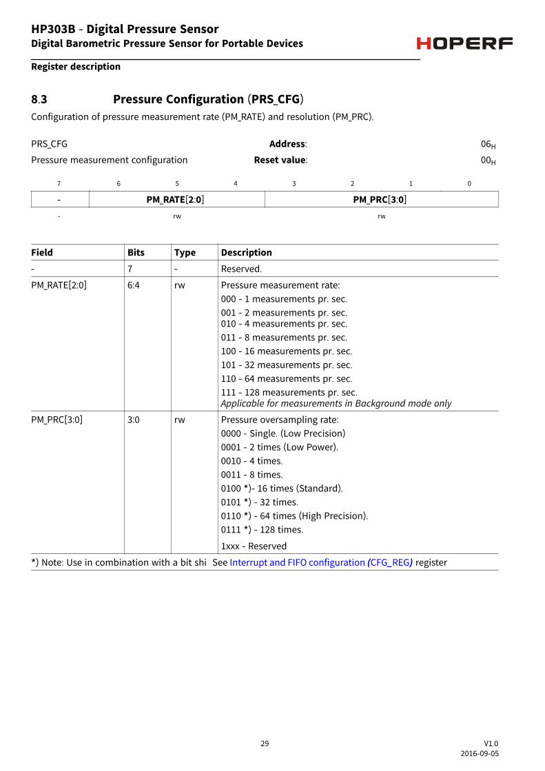
8.3 Pressure Configuration (PRS_CFG)Configuration of pressure measurement rate (PM_RATE) and resolution (PM_PRC).
PRS_CFG Address: 06H
Pressure measurement configuration Reset value: 00H
7 6 5 4 3 2 1 0
- PM_RATE[2:0] PM_PRC[3:0]
- rw rw
Field Bits Type Description- 7 - Reserved.
PM_RATE[2:0] 6:4 rw Pressure measurement rate:000 - 1 measurements pr. sec.001 - 2 measurements pr. sec.010 - 4 measurements pr. sec.011 - 8 measurements pr. sec.100 - 16 measurements pr. sec.101 - 32 measurements pr. sec.110 - 64 measurements pr. sec.111 - 128 measurements pr. sec.Applicable for measurements in Background mode only
PM_PRC[3:0] 3:0 rw Pressure oversampling rate:0000 - Single. (Low Precision)0001 - 2 times (Low Power).0010 - 4 times.0011 - 8 times.0100 *)- 16 times (Standard).0101 *) - 32 times.0110 *) - 64 times (High Precision).0111 *) - 128 times.
1xxx - Reserved
*) Note: Use in combination with a bit shi See registerInterrupt and FIFO configuration (CFG_REG)
Digital Barometric Pressure Sensor for Portable Devices
Register description
29 V1.02016-09-05
HP303B - Digital Pressure Sensor

Table 16 Precision (PaRMS) and pressure measurement time (ms) versus oversampling rate
Oversampling(PRC[3:0])
Single(0000)
2 times(0001)
4 times(0010)
8 times(0011)
16 times(0100)
32 times(0101)
64 times(0110)
128times(0111)
Measurement time(ms)
3.6 5.2 8.4 14.8 27.6 53.2 104.4 206.8
Precision (PaRMS) 5 2.5 1.2 0.9 0.5
Table 17 Estimated current consumption (uA)
Oversampling(PRC[3:0])
Single(0000)
2 times(0001)
4 times(0010)
8 times(0011)
16 times(0100)
32 times(0101)
64 times(0110)
128times(0111)Measurements pr
sec.(PM_RATE([2:0])
1 (000) 2.1 2.7 3.8 6.1 11 20 38 75
2 (001)
4 (010)
8 (011) Note: The current consumption can be calculated as the Measurement Rate *Current Consumption of 1 measurement per. sec.
n.a.
16 (100) n.a. n.a.
32 (101) n.a. n.a. n.a.
64 (110) n.a. n.a. n.a. n.a.
128 (111) n.a. n.a. n.a. n.a. n.a. n.a.
Note: The table shows the possible combinations of Pressure Measurement Rate and oversampling when notemperature measurements are performed. When temperature measurements are performed the possiblecombinations are limited to Ratetemperature x Measurement Timetemperature + Ratepressure x MeasurementTimepressure < 1 second.The temperature measurement time versus temperature oversampling rate is similar with pressuremeasurement time versus pressure oversampling rate
Digital Barometric Pressure Sensor for Portable Devices
Register description
30 V1.02016-09-05
HP303B - Digital Pressure Sensor

8.4 Temperature Configuration(TMP_CFG)Configuration of temperature measurement rate (TMP_RATE) and resolution (TMP_PRC).
TMP_CFG Address: 07H
Temperature measurement configuration Reset value: 00H
7 6 5 4 3 2 1 0
TMP_EXT TMP_RATE[6:4] TMP_PRC[3:0]
rw rw - rw
Field Bits Type DescriptionTMP_EXT 7 rw Temperature measurement
0 - Internal sensor (in ASIC)1 - External sensor (in pressure sensor MEMS element)Note: It is highly recommended to use the same temperaturesensor as the source of the calibration coecents Please see the ont Source register
TMP_RATE[2:0] 6:4 rw Temperature measurement rate:000 - 1 measurement pr. sec.001 - 2 measurements pr. sec.010 - 4 measurements pr. sec.011 - 8 measurements pr. sec.100 - 16 measurements pr. sec.101 - 32 measurements pr. sec.110 - 64 measurements pr. sec.111 - 128 measurements pr. sec..Applicable for measurements in Background mode only
TMP_PRC[2:0] 3:0 rw Temperature oversampling (precision):0000 - single. (Default) - Measurement time 3.6 ms.Note: Following are optional, and may not be relevant:0001 - 2 times.0010 - 4 times.0011 - 8 times.0100 - 16 times.0101 - 32 times.0110 - 64 times..0111 - 128 times.1xxx - Reserved.
Digital Barometric Pressure Sensor for Portable Devices
Register description
31 V1.02016-09-05
HP303B - Digital Pressure Sensor

8.5 Sensor Operating Mode and Status (MEAS_CFG)Setup measurement mode.
MEAS_CFG Address: 08H
Measurement configuration Reset value: C0H
7 6 5 4 3 2 1 0
COEF_RDY SENSOR_RDY TMP_RDY PRS_RDY - MEAS_CTRL
r r r r - rw
Field Bits Type DescriptionCOEF_RDY 7 r Coeicients will be read to the Coeicents Registers aer start-
up:0 - Coeicients are not available yet.1 - Coeicients are available.
SENSOR_RDY 6 r The pressure sensor is running through self initialization aerstart-up.0 - Sensor initialization not complete1 - Sensor initialization completeIt is recommend not to start measurements until the sensor hascompleted the self intialization.
TMP_RDY 5 r Temperature measurement ready1 - New temperature measurement is ready. Cleared whentemperature measurement is read.
PRS_RDY 4 r Pressure measurement ready1 - New pressure measurement is ready. Cleared whenpressurement measurement is read.
- 3 - Reserved.
MEAS_CTRL 2:0 rw Set measurement mode and type:Standby Mode000 - Idle / Stop background measurementCommand Mode001 - Pressure measurement010 - Temperature measurement011 - na.100 - na.Background Mode101 - Continous pressure measurement110 - Continous temperature measurement111 - Continous pressure and temperature measurement
Digital Barometric Pressure Sensor for Portable Devices
Register description
32 V1.02016-09-05
HP303B - Digital Pressure Sensor

8.6 Interrupt and FIFO configuration (CFG_REG)Configuration of interupts, measurement data shi and FIFO enable.
CFG_REG Address: 09H
Configuration register Reset value: 00H
7 6 5 4 3 2 1 0
INT_HL INT_FIFO INT_TMP INT_PRS T_SHIFT P_SHIFT FIFO_EN SPI_MODErw rw rw rw rw rw rw rw
Field Bits Type DescriptionINT_HL 7 rw Interupt (on SDO pin) active level:
0 - Active low.1 - Active high.
INT_FIFO 6 rw Generate interupt when the FIFO is full:0 - Disable.1 - Enable.
INT_TMP 5 rw Generate interupt when a temperature measurement is ready:0 - Disable.1 - Enable.
INT_PRS 4 rw Generate interupt when a pressure measurement is ready:0 - Disable.1 - Enable.
T_SHIFT 3 rw Temperature result bitshi0 - no shi1 - shi result right in data register.Note: Must be set to '1' when the oversampling rate is >8 times.
P_SHIFT 2 rw Pressure result bitshi0 - no shi1 - shi result right in data register.Note: Must be set to '1' when the oversampling rate is >8 times.
FIFO_EN 1 rw Enable the FIFO:0 - Disable.1 - Enable.
SPI_MODE 0 rw Set SPI mode:0 - 4-wire interface.1 - 3-wire interface.
Digital Barometric Pressure Sensor for Portable Devices
Register description
33 V1.02016-09-05
HP303B - Digital Pressure Sensor

8.7 Interrupt Status (INT_STS)Interrupt status register. The register is cleared on read.
INT_STS Address: 0AH
Interrupt status Reset value: 00H
7 6 5 4 3 2 1 0
- INT_FIFO_FULL INT_TMP INT_PRS
- r r r
Field Bits Type Description- 7:3 - Reserved.
INT_FIFO_FULL 2 r Status of FIFO interrupt0 - Interrupt not active1 - Interrupt active
INT_TMP 1 r Status of temperature measurement interrupt0 - Interrupt not active1 - Interrupt active
INT_PRS 0 r Status of pressure measurement interrupt0 - Interrupt not active1 - Interrupt active
Digital Barometric Pressure Sensor for Portable Devices
Register description
34 V1.02016-09-05
HP303B - Digital Pressure Sensor
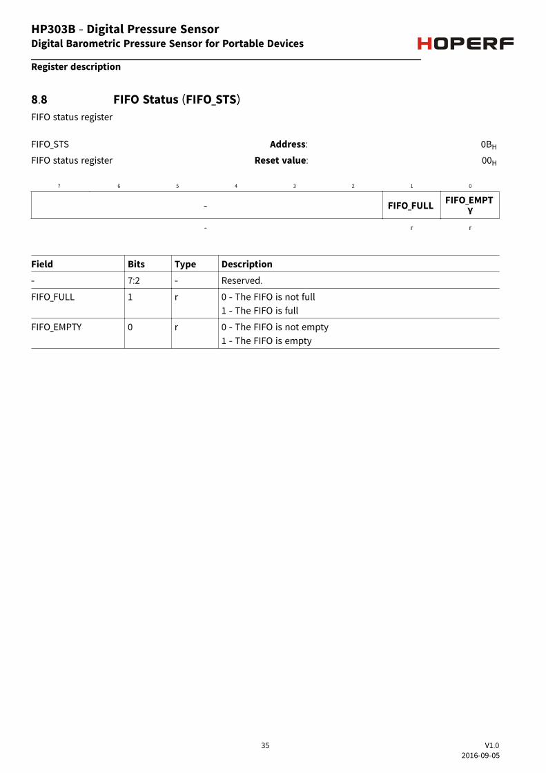
8.8 FIFO Status (FIFO_STS)FIFO status register
FIFO_STS Address: 0BH
FIFO status register Reset value: 00H
7 6 5 4 3 2 1 0
- FIFO_FULL FIFO_EMPTY
- r r
Field Bits Type Description- 7:2 - Reserved.
FIFO_FULL 1 r 0 - The FIFO is not full1 - The FIFO is full
FIFO_EMPTY 0 r 0 - The FIFO is not empty1 - The FIFO is empty
Digital Barometric Pressure Sensor for Portable Devices
Register description
35 V1.02016-09-05
HP303B - Digital Pressure Sensor

8.9 o Reset and FIFO flush (RESET)Flush FIFO or generate so reset.
RESET Address: 0CH
FIFO flush and so reset Reset value: 00H
7 6 5 4 3 2 1 0
FIFO_FLUSH - SOFT_RSTw - w
Field Bits Type DescriptionFIFO_FLUSH 7 w FIFO flush
1 - Empty FIFOAer reading out all data from the FIFO, write '1' to clear all olddata.
- 6:4 - Reserved.
SOFT_RST 3:0 w Write '1001' to generate a so reset. A so reset will run thoughthe same sequences as in power-on reset.
8.10 Product and Revision ID (ID)Product and Revision ID.
ID Address: 0DH
Product and revision ID Reset value: 0x10H
7 6 5 4 3 2 1 0
REV_ID PROD_IDr r
Field Bits Type DescriptionREV_ID 7:4 r Revision ID
PROD_ID 3:0 r Product ID
Digital Barometric Pressure Sensor for Portable Devices
Register description
36 V1.02016-09-05
HP303B - Digital Pressure Sensor

(COEF)The Calibration Coeicients register contains the 2´s complement coeicients that are used to calculate thecompensated pressure and temperature values.
Coefficients Addr. bit7 bit6 bit5 bit4 bit3 bit2 bit1 bit0c0 0x10 c0 [11:4]
c0/c1 0x11 c0 [3:0] c1 [11:8]
c1 0x12 c1[7:0]
c00 0x13 c00 [19:12]
c00 0x14 c00 [11:4]
c00/c10 0x15 c00 [3:0] c10 [19:16]
c10 0x16 c10 [15:8]
c10 0x17 c10 [7:0]
c01 0x18 c01 [15:8]
c01 0x19 c01 [7:0]
c11 0x1A c11 [15:8]
c11 0x1B c11 [7:0]
c20 0x1C c20 [15:8]
c20 0x1D c20 [7:0]
c21 0x1E c21 [15:8]
c21 0x1F c21 [7:0]
c30 0x20 c30 [15:8]
c30 0x21 c30 [7:0]
Note: Generate the decimal numbers out of the calibration coeicients registers data: C20 := reg0x1D + reg0x1C * 2^ 8
if (C20 > (2^15 - 1)) C20 := C20 - 2^16end if
C0 := (reg0x10 * 2^ 4) + ((reg0x11 / 2^4) & 0x0F)if (C0 > (2^11 - 1)) C0 := C0 - 2^12end if
Digital Barometric Pressure Sensor for Portable Devices
Register description
37 V1.0
HP303B - Digital Pressure Sensor
2016-09-05
HP303B - Digital Pressure Sensor
Table 18 Calibration Coefficients
8.11 Calibration Coefficients
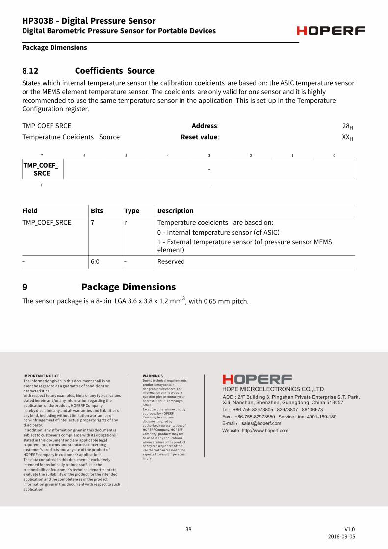
8.12 Coefficients SourceStates which internal temperature sensor the calibration coeicients are based on: the ASIC temperature sensoror the MEMS element temperature sensor. The coeicients are only valid for one sensor and it is highlyrecommended to use the same temperature sensor in the application. This is set-up in the TemperatureConfiguration register.
TMP_COEF_SRCE Address: 28H
Temperature Coeicients Source Reset value: XXH
7 6 5 4 3 2 1 0
TMP_COEF_SRCE -
r -
Field Bits Type DescriptionTMP_COEF_SRCE 7 r Temperature coeicients are based on:
0 - Internal temperature sensor (of ASIC)1 - External temperature sensor (of pressure sensor MEMSelement)
- 6:0 - Reserved
9 Package DimensionsThe sensor package is a 8-pin LGA 3.6 x 3.8 x 1.2 mm3, with 0.65 mm pitch.
Digital Barometric Pressure Sensor for Portable Devices
Package Dimensions
38 V1.02016-09-05
HP303B - Digital Pressure Sensor
IMPORTANT NOTICEThe information given in this document shall in noevent be regarded as a guarantee of conditions orcharacteristics .With respect to any examples, hints or any typical valuesstated herein and/or any information regarding theapplication of the product, HOPERF Companyhereby disclaims any and all warranties and liabilities ofany kind, including without limitation warranties ofnon-infringement of intellectual property rights of anythird party.In addition, any information given in this document issubject to customer’s compliance with its obligationsstated in this document and any applicable legalrequirements, norms and standards concerningcustomer’s products and any use of the product ofHOPERF company in customer’s applications.The data contained in this document is exclusivelyintended for technically trained staff. It is theresponsibility of customer’s technical departments toevaluate the suitability of the product for the intendedapplication and the completeness of the productinformation given in this document with respect to suchapplication.
WARNINGSDue to technical requirements products may contain dangerous substances. For information on the types in question please contact your nearest HOPERF company’s office.Except as otherwise explicitly approved by HOPERF Company in a written document signed byauthorized representatives of HOPERF Company, HOPERF Company’ products may not be used in any applications where a failure of the product or any consequences of the use thereof can reasonablybe expected to result in personal injury.