as-mlv-p2 · as-mlv-p2 − pn ai ssignment figure 2: pin diagram figure 3: pin description pin...
TRANSCRIPT

AS-MLV-P2Air Quality Sensor
The ams AS-MLV-P2 is a MOS (metal oxide semiconductor) based gas sensor component. It was specifically designed for a broad detection of reducing gases such as VOCs (volatile organic compounds) and CO (carbon monoxide) associated with bad air quality. The AS-MLV-P2 sensor component is a MEMS (micro electromechanical system) device using silicon wafer technology.
Ordering Information and Content Guide appear at end of datasheet.
Key Benefits & FeaturesThe benefits and features of AS-MLV-P2, Air Quality Sensor are listed below:
Figure 1:Added Value of Using AS-MLV-P2 Sensor
Applications
• Indoor air monitor
• Kitchen hood
• Weather stations
• Smart home
• Internet of Things (IoT)
Benefits Features
• High sensitivity to volatile organic compounds (VOCs) • Limit of detection in a low ppm range
• Very low power consumption • 34 mW at 300°C
• Maintenance free • 10 year lifetime
• Reflow capable • Surface Mount Package
General Description
ams Datasheet Page 1[v1-01] 2015-Oct-12 Document Feedback

AS-MLV-P2 − Pin Assignment
Figure 2:Pin Diagram
Figure 3:Pin Description
Pin Number Pin Name Description
1 RS1 Sensor electrode 1
2 RH1 Heater 1
3 RS2 Sensor electrode 2
4 RH2 Heater 2
Pin Assignment
1
2
4
3
Pin 1 Indicator
Page 2 ams Datasheet Document Feedback [v1-01] 2015-Oct-12

AS-MLV-P2 − Environmental Specifications
The sensor element characteristics are valid under the following environmental conditions:
Figure 4:Environmental Operating Conditions
Note(s):
1. The sensor must be kept separate from all sourced of silicone contamination to fulfill the functional and lifetime requirements.
Description Value
Ambient Operating Range
Temperature range 0°C to 50°C
Humidity range (relative humidity, non-condensing)
5% to 95%
Ambient Storage Range
Storage temperature range -40°C to 85°C
Storage humidity range (relative humidity, non-condensing)
5% to 95%
Air Flow
Experienced air velocity 0m/s to 4m/s
Environmental Specifications
ams Datasheet Page 3[v1-01] 2015-Oct-12 Document Feedback
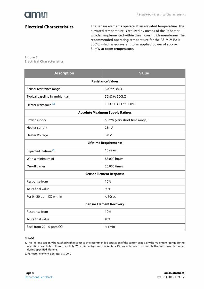
AS-MLV-P2 − Electrical Characteristics
The sensor elements operate at an elevated temperature. The elevated temperature is realized by means of the Pt heater which is implemented within the silicon nitride membrane. The recommended operating temperature for the AS-MLV-P2 is 300°C, which is equivalent to an applied power of approx. 34mW at room temperature.
Figure 5:Electrical Characteristics
Note(s):
1. This lifetime can only be reached with respect to the recommended operation of the sensor. Especially the maximum ratings during operation have to be followed carefully. With this background, the AS-MLV-P2 is maintenance free and shall require no replacement during specified lifetime.
2. Pt heater element operates at 300°C
Description Value
Resistance Values
Sensor resistance range 3kΩ to 3MΩ
Typical baseline in ambient air 50kΩ to 500kΩ
Heater resistance (2) 150Ω ± 30Ω at 300°C
Absolute Maximum Supply Ratings
Power supply 50mW (very short time range)
Heater current 25mA
Heater Voltage 3.0 V
Lifetime Requirements
Expected lifetime (1) 10 years
With a minimum of 85.000 hours
On/off cycles 20.000 times
Sensor Element Response
Response from 10%
To its final value 90%
For 0 - 20 ppm CO within < 10sec
Sensor Element Recovery
Response from 10%
To its final value 90%
Back from 20 – 0 ppm CO < 1min
Electrical Characteristics
Page 4 ams Datasheet Document Feedback [v1-01] 2015-Oct-12
AS-MLV-P2 − Detailed Description
AS-MLV-P2 heater and inter-digital electrode structures use Platinum and are implemented in an approximately one micrometer-thin silicon nitride membrane to achieve ultimate stability and lowest possible power consumption. A highly sensitive and long-term stable polycrystalline tin dioxide-based sensitive material is deposited on the inter-digital electrodes. At an elevated operation temperature of approx. 300°C, this catalytically active material shows a gas concentration dependent resistance change.
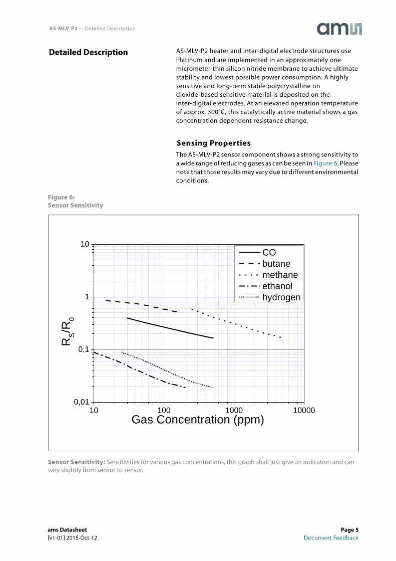
Sensing PropertiesThe AS-MLV-P2 sensor component shows a strong sensitivity to a wide range of reducing gases as can be seen in Figure 6. Please note that those results may vary due to different environmental conditions.
Figure 6:Sensor Sensitivity
Sensor Sensitivity: Sensitivities for various gas concentrations, this graph shall just give an indication and can vary slightly from sensor to sensor.
Detailed Description
10 100 1000 100000,01
0,1
1
10
RS/R
0
Gas Concentration (ppm)
CO butane methane ethanol hydrogen
ams Datasheet Page 5[v1-01] 2015-Oct-12 Document Feedback

AS-MLV-P2 − Detailed Description
Cross SensitivitiesDue to the basic operation principle of MOS gas sensors, the AS-MLV-P2 sensor component does have a cross sensitivity to humidity changes. This effect provides additional information and widens the application range for the sensor. This feature especially supports applications in environments where the detection of significant humidity changes is supporting the functionality, such as bathroom and kitchen environments. Figure 7 shows the dependency of humidity using the example of CO signals to get a visualized feeling for the effect. Please note that this dataset is just meant to be an example and the values may vary from sensor to sensor.
Figure 7:Cross Sensitivity of Humidity for CO
Cross Sensitivity of Humidity for CO: Cross sensitivity of humidity for the example of CO. This data is just meant to be a visualization of the influence of humidity and will vary slightly from sensor to sensor.
30 40 50 60 70 800,1
1
10
RS/R
0
% r.h.
30ppm CO
Page 6 ams Datasheet Document Feedback [v1-01] 2015-Oct-12

AS-MLV-P2 − Application Information
Due to the characteristics of the sensor, there are some issues to be taken care of while implementing. The operation temperature of the sensor has to be kept constant; therefore the circuit on heater site shall have the possibility to be regulated. The critical issue of the sensor resistance is the wide range of values which has to be covered during operation.
All following circuits are meant to be examples which have to be adapted carefully to the different applications.
Sensor ResistanceThe sensitive layer can change its resistance over several orders of magnitude, depending on the production and gas exposition. The electrical power dissipated in the sensitive layer must be limited and must not exceed 2mA. This power shall also avoid performing high changes over short time. Because of this issue a measuring range shifting realized with series resistors will have an effect to the sensor signal and should be avoided.
As a suggestion we measure the sensor resistance with a simple voltage divider as shown in Figure 8. VH determines the heater voltage and therefore the operation temperature of the sensor. This regulation is described in a later chapter. Here we focus on the sensor resistance measuring. To meet the described specification a value of 10kOhm or 100kOhm for the load resistor (RL) and a Voltage of 5V for VS is a good starting point for a broad range of the sensor applications. A high precision noise free voltage source is recommended for generating VS. RS and RL form a voltage divider, which can be used to calculate RS (see EQ 1).
Figure 8:A Basic Measurement Circuit for the Sensor Resistance
Application Information
(EQ1) RS RLVS
Vout------------ 1–
=
VoutVs
RL
RS
VH
1 3
2 4
ams Datasheet Page 7[v1-01] 2015-Oct-12 Document Feedback

AS-MLV-P2 − Application Information
The resolution of the measurement of RS is recommended to be better or equal to 1% of the actual reading. This allows making use of the full performance of the sensor. The requirements for the A/D conversion of the output voltage Vout is described in the following section.
The input impedance of the A/D converter should be high enough not to influence the level of the voltage divider, a ration of at least 10 between input impedance and values of RS and/or RL is recommended.
Averaging A/D conversion procedures are recommended in order to suppress fast resistance changes from the sensitive layer (resistive noise and change of the resistance due to chemical influences).
In order to achieve 1% of precision of the read-out of RS, the A/D conversion of Vout needs lower resolution, if sensor- and load resistor match. A larger difference between RS and RL requires a higher resolution of the A/D conversion. The following figure gives a few examples for VS = 5V.
Figure 9:Examples for Readout of RS with 1% Resolution (VS=5V)
Examples for Readout of RS with 1% Resolution: The series resistor RL has also the functionality to limit the power dissipated to the sensitive layer.
If the A/D conversion is single ended (common ground) it might be useful to change the sequence of load resistor and sensor resistor in the voltage divider. This enables to increase the resolution by using a lower reference voltage for the A/D conversion.
RS [Ohm] RL [Ohm] Vout [V] A/D Voltage Step for 1% Resolution
100 10k 4.95 0.5mV
1k 10k 4.5454 4.1mV
10k 10k 2.5 12.4mV
100k 10k 0.4545 4.1mV
1M 10k 0.0495 0.5mV
1k 100k 4.95 0.5mV
10k 100k 4.5454 4.1mV
100k 100k 2.5 12.4mV
1M 100k 0.4545 4.1mV
Page 8 ams Datasheet Document Feedback [v1-01] 2015-Oct-12
AS-MLV-P2 − Application Information
A constant current source can also be used to read-out the sensitive layer. In this case the electrical power dissipated in the sensitive layer must be limited and must not exceed 1mW for all values of RS.
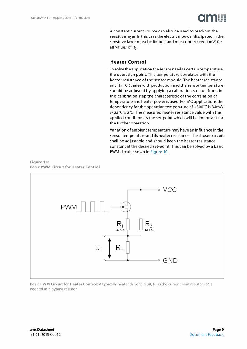
Heater ControlTo solve the application the sensor needs a certain temperature, the operation point. This temperature correlates with the heater resistance of the sensor module. The heater resistance and its TCR varies with production and the sensor temperature should be adjusted by applying a calibration step up front. In this calibration step the characteristic of the correlation of temperature and heater power is used. For iAQ applications the dependency for the operation temperature of ~300°C is 34mW @ 23°C ± 2°C. The measured heater resistance value with this applied conditions is the set-point which will be important for the further operation.
Variation of ambient temperature may have an influence in the sensor temperature and its heater resistance. The chosen circuit shall be adjustable and should keep the heater resistance constant at the desired set-point. This can be solved by a basic PWM circuit shown in Figure 10.
Figure 10:Basic PWM Circuit for Heater Control
Basic PWM Circuit for Heater Control: A typically heater driver circuit, R1 is the current limit resistor, R2 is needed as a bypass resistor
ams Datasheet Page 9[v1-01] 2015-Oct-12 Document Feedback
AS-MLV-P2 − Application Information
To use the example a p-channel MOSFET is mandatory; using an n-channel will need a change of the overall circuit design. In this case the Voltage VCC is 5V with a max ripple of 20mV, but the circuit is also valid for 3.3V. The circuit should be designed to achieve a PWM of 30-60% depending on heater set-point. This range gives the security that all specified environmental temperature ranges can be compensated.
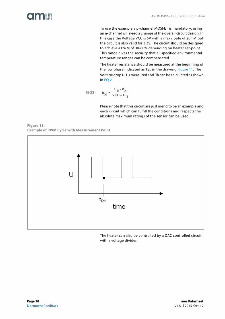
The heater resistance should be measured at the beginning of the low phase indicated as TRH in the drawing Figure 11. The Voltage drop UH is measured and Rh can be calculated as shown in EQ 2.
Please note that this circuit are just mend to be an example and each circuit which can fulfill the conditions and respects the absolute maximum ratings of the sensor can be used.
Figure 11:Example of PWM Cycle with Measurement Point
The heater can also be controlled by a DAC controlled circuit with a voltage divider.
(EQ2) RHUH R2⋅
VCC UH–---------------------------=
Page 10 ams Datasheet Document Feedback [v1-01] 2015-Oct-12

AS-MLV-P2 − Application Information
Heater CalibrationAs mentioned in the previous chapter the each sensor has its own set-point at the operation temperature. This set-point can be determined by a previous calibration step. This means that the AS-MLV-P2 is started at room temperature (23°C ± 3°C) and powered with 34mW. With these conditions the heater resistance is measured and stored into the EEPROM. This heater resistance is the certain set-point which is kept constant with the regulating PWM during operation.
General CharacteristicsThe sensor has some native characteristics which should be considered in the application development.
Burn-In Behavior Once in lifetime the sensor performs a special burn in behavior, this curve is characterized in three phases which are described with the following figure.
Figure 12:Burn-In of Sensor
Description Duration
Phase 1 Fast increase of the sensor resistance ~ 10 hours
Phase 2 Plateau with nearly stable baseline ~ 12 hours
Phase 3 Long drift like decrease of the sensor resistance > 4 days
ams Datasheet Page 11[v1-01] 2015-Oct-12 Document Feedback

AS-MLV-P2 − Application Information
A characteristic example is shown in Figure 13. This behavior is caused due to manufacturing issues and is mandatory. After once following this issue it will never appear again. During the burn in phase the resistance range can be exceeded considerably.
Figure 13:Characteristic Resistance Curve during Burn-In
Page 12 ams Datasheet Document Feedback [v1-01] 2015-Oct-12

AS-MLV-P2 − Application Information
Run-InEach time after powering the sensor, the baseline of the sensitive layer performs a small run in phase. The curve is characterized with a steady increasing resistance. The length of this phase is depending on the sensors history. The longer the sensor was unpowered the longer the run in phase will take. The standard duration is approx. 3-5 minutes.
Figure 14:Run-In Phase of Sensor
0 300 600 900 1200 1500 1800 2100 2400 2700 3000100000
150000
200000
250000
300000
350000
400000
450000
500000
550000
600000
Res
ista
nce
[Ω]
Time [sec]
ams Datasheet Page 13[v1-01] 2015-Oct-12 Document Feedback
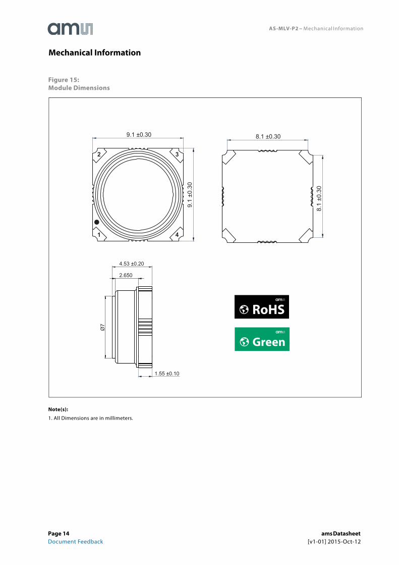
AS-MLV-P2 − Mechanical Information
Figure 15:Module Dimensions
Note(s):
1. All Dimensions are in millimeters.
Mechanical Information
Green
RoHS
8.1 ±0.30
8.1
±0.3
0
9.1 ±0.30
9.1
±0.3
0
1
2
4
3
4.53 ±0.20
2.650
Ø7
1.55 ±0.10
Page 14 ams Datasheet Document Feedback [v1-01] 2015-Oct-12

AS-MLV-P2 − Mechanical Information
Figure 16:Module Markings
Figure 17:Module and Marking Elements
Item Description
PCB Material FR4 with gold surface (7μm Ni / 3μm Au)
Connector Edge connector
Marking PIN1 White mark
Label Laser mark AS-MLV-P2
Product name (first row) AS-MLV-P2
Serial number (second row)
SNYYxxxxxxx
YY → two digits production year
xxxxxxx → 7 digits running number
AS-MLV-P2SNYYxxxxxxx
ams Datasheet Page 15[v1-01] 2015-Oct-12 Document Feedback

AS-MLV-P2 − Mechanical Information
Figure 18:Tape and Reel Information
Description Items Symbol Value Unit Tolerance
Length Ao 9.70
mm ±0.10Width Bo 9.70
Depth Ko 5.00
Pitch P1 12.00
Angle θ1 3Degree Max.
Angle θ2 3
Page 16 ams Datasheet Document Feedback [v1-01] 2015-Oct-12

AS-MLV-P2 − Mechanical Information
Note(s):
1. All dimensions are in millimeters unless otherwise stated.
2. Unspecified dimension tolerance should be ±0.10mm.
3. Cumulative tolerance of 10 sprocket holes is ±0.20mm.
Perforation
Diameter ΘD0 1.50
mm
+0.10
Diameter ΘD1 1.50 -0.00
Pitch P0 4.00
±0.10
Pitch P2 2.00
Position E 1.75
Distance between center line
Width F 7.50
Carrier tape material
Type Echips
Width W 16.00mm
±0.30
Thickness T 0.50 ±0.05
Requirement/Notice
1. Camber 250mm. Should be less than 1.00mm by Camber gauge.2. Must conform to E.I.A. Standard.
Description Items Symbol Value Unit Tolerance
ams Datasheet Page 17[v1-01] 2015-Oct-12 Document Feedback
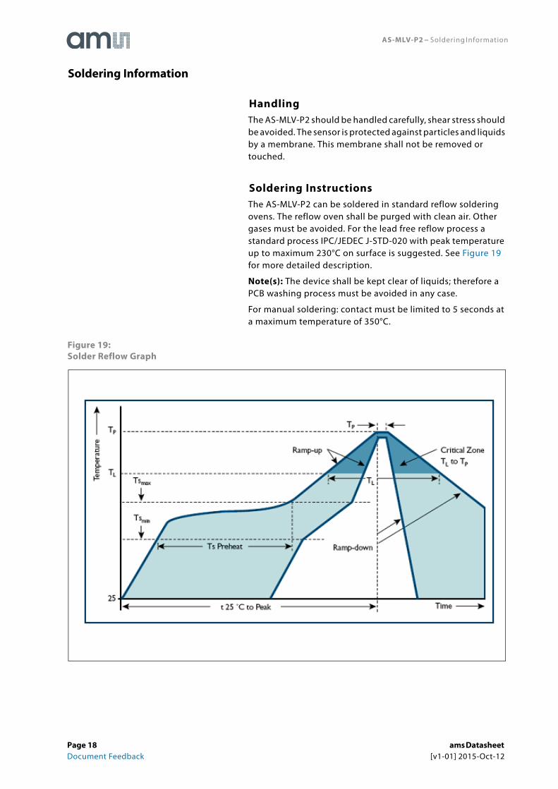
AS-MLV-P2 − Soldering Information
HandlingThe AS-MLV-P2 should be handled carefully, shear stress should be avoided. The sensor is protected against particles and liquids by a membrane. This membrane shall not be removed or touched.
Soldering InstructionsThe AS-MLV-P2 can be soldered in standard reflow soldering ovens. The reflow oven shall be purged with clean air. Other gases must be avoided. For the lead free reflow process a standard process IPC/JEDEC J-STD-020 with peak temperature up to maximum 230°C on surface is suggested. See Figure 19 for more detailed description.
Note(s): The device shall be kept clear of liquids; therefore a PCB washing process must be avoided in any case.
For manual soldering: contact must be limited to 5 seconds at a maximum temperature of 350°C.
Figure 19:Solder Reflow Graph
Soldering Information
Page 18 ams Datasheet Document Feedback [v1-01] 2015-Oct-12
AS-MLV-P2 − Ordering & Contact Information
Figure 20:Ordering Information
Buy our products or get free samples online at:www.ams.com/ICdirect
Technical Support is available at:www.ams.com/Technical-Support
Provide feedback about this document at:www.ams.com/Document-Feedback
For further information and requests, e-mail us at:[email protected]
For sales offices, distributors and representatives, please visit: www.ams.com/contact
Headquartersams AGTobelbaderstrasse 308141 UnterpremstaettenAustria, Europe
Tel: +43 (0) 3136 500 0
Website: www.ams.com
Ordering Code Marking Delivery Form Delivery Quantity
AS-MLV-P2 AS-MLV-P2 Tape & Reel 900
Ordering & Contact Information
ams Datasheet Page 19[v1-01] 2015-Oct-12 Document Feedback
AS-MLV-P2 − RoHS Compliant & ams Green Statement
RoHS: The term RoHS compliant means that ams AG products fully comply with current RoHS directives. Our semiconductor products do not contain any chemicals for all 6 substance categories, including the requirement that lead not exceed 0.1% by weight in homogeneous materials. Where designed to be soldered at high temperatures, RoHS compliant products are suitable for use in specified lead-free processes.
ams Green (RoHS compliant and no Sb/Br): ams Green defines that in addition to RoHS compliance, our products are free of Bromine (Br) and Antimony (Sb) based flame retardants (Br or Sb do not exceed 0.1% by weight in homogeneous material).
Important Information: The information provided in this statement represents ams AG knowledge and belief as of the date that it is provided. ams AG bases its knowledge and belief on information provided by third parties, and makes no representation or warranty as to the accuracy of such information. Efforts are underway to better integrate information from third parties. ams AG has taken and continues to take reasonable steps to provide representative and accurate information but may not have conducted destructive testing or chemical analysis on incoming materials and chemicals. ams AG and ams AG suppliers consider certain information to be proprietary, and thus CAS numbers and other limited information may not be available for release.
RoHS Compliant & ams Green Statement
Page 20 ams Datasheet Document Feedback [v1-01] 2015-Oct-12

AS-MLV-P2 − Copyrights & Disclaimer
Copyright ams AG, Tobelbader Strasse 30, 8141 Unterpremstaetten, Austria-Europe. Trademarks Registered. All rights reserved. The material herein may not be reproduced, adapted, merged, translated, stored, or used without the prior written consent of the copyright owner.
Devices sold by ams AG are covered by the warranty and patent indemnification provisions appearing in its General Terms of Trade. ams AG makes no warranty, express, statutory, implied, or by description regarding the information set forth herein. ams AG reserves the right to change specifications and prices at any time and without notice. Therefore, prior to designing this product into a system, it is necessary to check with ams AG for current information. This product is intended for use in commercial applications. Applications requiring extended temperature range, unusual environmental requirements, or high reliability applications, such as military, medical life-support or life-sustaining equipment are specifically not recommended without additional processing by ams AG for each application. This product is provided by ams AG “AS IS” and any express or implied warranties, including, but not limited to the implied warranties of merchantability and fitness for a particular purpose are disclaimed.
ams AG shall not be liable to recipient or any third party for any damages, including but not limited to personal injury, property damage, loss of profits, loss of use, interruption of business or indirect, special, incidental or consequential damages, of any kind, in connection with or arising out of the furnishing, performance or use of the technical data herein. No obligation or liability to recipient or any third party shall arise or flow out of ams AG rendering of technical or other services.
Copyrights & Disclaimer
ams Datasheet Page 21[v1-01] 2015-Oct-12 Document Feedback

AS-MLV-P2 − Document Status
Document Status Product Status Definition
Product Preview Pre-Development
Information in this datasheet is based on product ideas in the planning phase of development. All specifications are design goals without any warranty and are subject to change without notice
Preliminary Datasheet Pre-Production
Information in this datasheet is based on products in the design, validation or qualification phase of development. The performance and parameters shown in this document are preliminary without any warranty and are subject to change without notice
Datasheet Production
Information in this datasheet is based on products in ramp-up to full production or full production which conform to specifications in accordance with the terms of ams AG standard warranty as given in the General Terms of Trade
Datasheet (discontinued) Discontinued
Information in this datasheet is based on products which conform to specifications in accordance with the terms of ams AG standard warranty as given in the General Terms of Trade, but these products have been superseded and should not be used for new designs
Document Status
Page 22 ams Datasheet Document Feedback [v1-01] 2015-Oct-12

AS-MLV-P2 − Revision Information
Note(s):
1. Page and figure numbers for the previous version may differ from page and figure numbers in the current revision.
2. Correction of typographical errors is not explicitly mentioned.
Changes from 1-00 (2015-Jul-10) to current revision 1-01 (2015-Oct-12) Page
Updated Figure 3 2
Updated EQ1 7
Updated Figure 8 7
Revision Information
ams Datasheet Page 23[v1-01] 2015-Oct-12 Document Feedback

AS-MLV-P2 − Content Guide
1 General Description1 Key Benefits & Features1 Applications
2 Pin Assignment3 Environmental Specifications4 Electrical Characteristics
5 Detailed Description5 Sensing Properties6 Cross Sensitivities
7 Application Information7 Sensor Resistance9 Heater Control11 Heater Calibration11 General Characteristics11 Burn-In Behavior13 Run-In
14 Mechanical Information
18 Soldering Information18 Handling18 Soldering Instructions
19 Ordering & Contact Information20 RoHS Compliant & ams Green Statement21 Copyrights & Disclaimer22 Document Status23 Revision Information
Content Guide
Page 24 ams Datasheet Document Feedback [v1-01] 2015-Oct-12