allen bradley controllogix ethernet setup...
TRANSCRIPT

TOP Server 5.19
Configuration Guide:
Allen Bradley ControlLogix Ethernet Device

Page 2 of 19
Table of Contents
Introduction 3
Channel Setup 3
Device Setup 7
Further Information 19

Page 3 of 19
Introduction
This document is intended to provide an easy to use reference guide on configuring a connection to an
Allen Bradley ControlLogix Ethernet device using the TOP Server 5. It is not intended to be comprehensive,
and the help file should be referenced for any additional information – if needed. This document will
describe the channel and device setup, and give a summary of the settings that will be encountered.
Channel Setup
1. The first step in configuring a connection to a ControlLogix device from TOP Server is to create a
Channel. A channel represents a communication medium from the PC running TOP server to the
device. In the case of a ControlLogix Ethernet connection, the Channel will represent the socket
that gets opened for communications.
2. The Channel name is user configurable, and will be how the Channel appears in the TOP Server
tree view – i.e. how clients will reference devices configured under this channel.
3. Click next and choose the Allen Bradley ControlLogix Ethernet driver from the Driver dropdown list.
This selection determines which protocol will be used to communicate over the channel. The
“Enable Diagnostics” checkbox has not impact on communications so can be left unchecked, but
statistic tags will be inactive until diagnostics are enabled.

Page 4 of 19
4. Click next and choose the appropriate Network Adapter that the channel should use for
communications. This Adapter should be on the same network as the devices TOP Server will be
communicating to. When left at Default the Operating Systems default adapter will be used.

Page 5 of 19
5. Click next to review the Write optimization settings for this Channel. These will generally be left at
the default value, but can be altered as needed.
a. Write all values for all tags will queue all write requests and issue them in the order they
were received.
b. Write only latest value for non-Boolean tags will not queue all writes, but only write the
last value that was received from the client application for any non-Boolean tags.
c. Write only latest value for all tags will not queue any writes, and simply write the last
value that was received from the client application for any points.
d. The Duty Cycle determines how many writes will be processed per 1 read request. Since
writes are treated with higher priority this can be used to improve communication rates in
write-heavy channels
Page 6 of 19
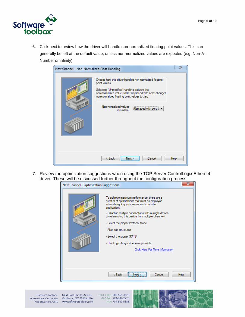
6. Click next to review how the driver will handle non-normalized floating point values. This can
generally be left at the default value, unless non-normalized values are expected (e.g. Non-A-
Number or infinity)
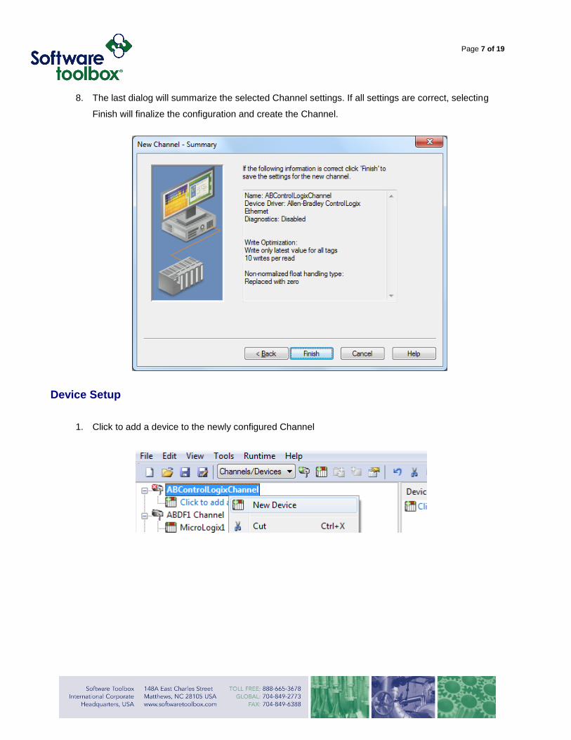
7. Review the optimization suggestions when using the TOP Server ControlLogix Ethernet driver. These will be discussed further throughout the configuration process.
Page 7 of 19
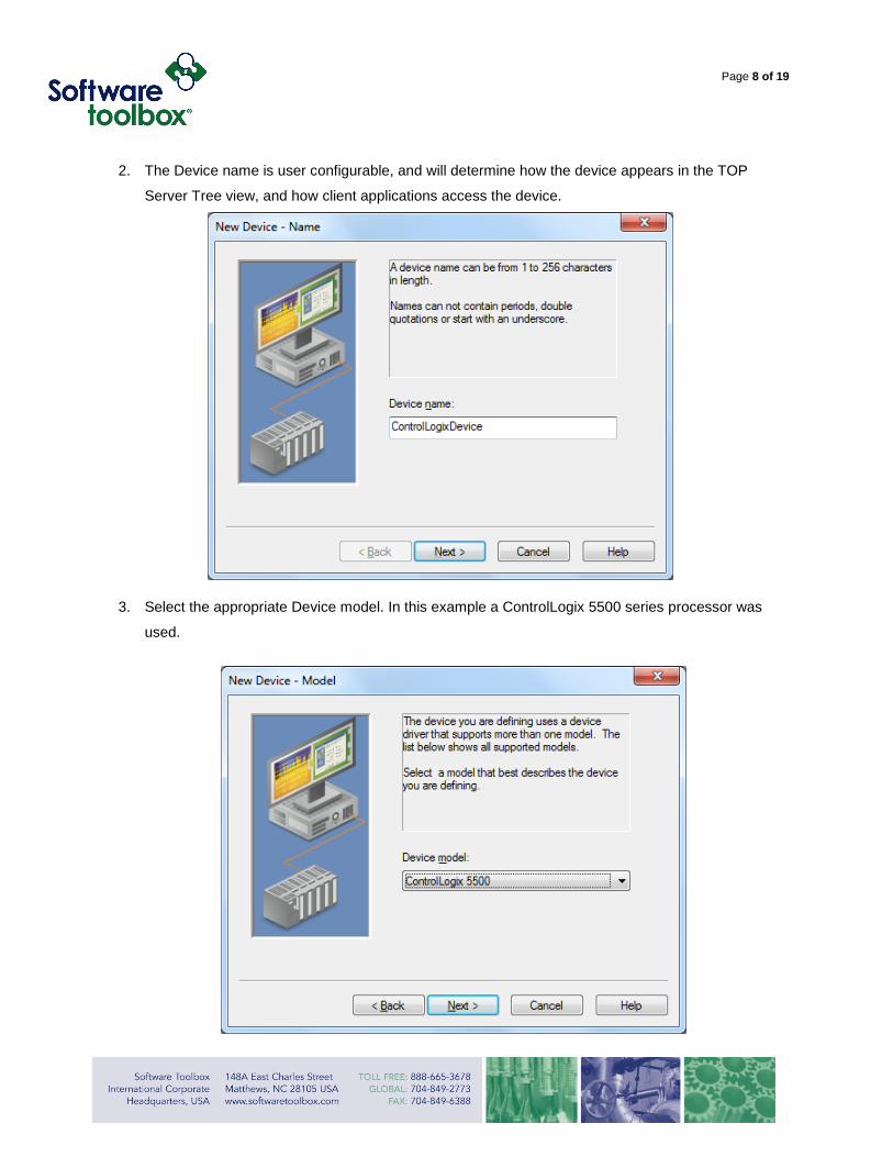
8. The last dialog will summarize the selected Channel settings. If all settings are correct, selecting
Finish will finalize the configuration and create the Channel.
Device Setup
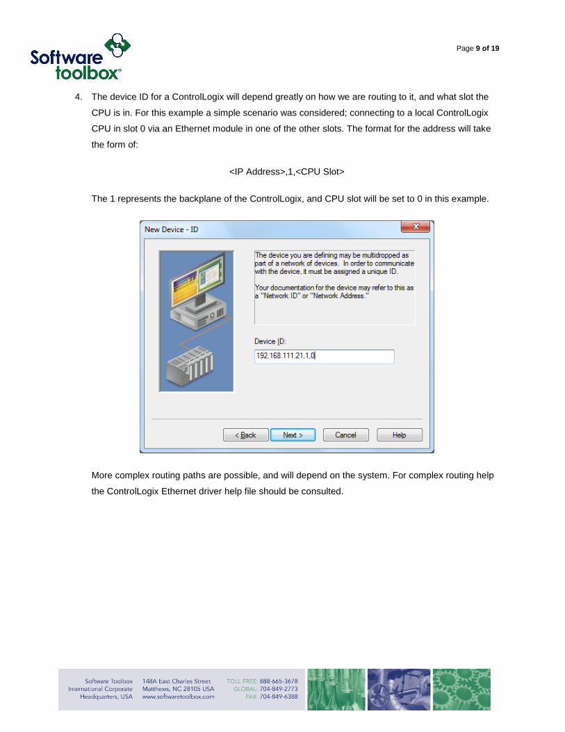
1. Click to add a device to the newly configured Channel
Page 8 of 19
2. The Device name is user configurable, and will determine how the device appears in the TOP
Server Tree view, and how client applications access the device.
3. Select the appropriate Device model. In this example a ControlLogix 5500 series processor was
used.
Page 9 of 19
4. The device ID for a ControlLogix will depend greatly on how we are routing to it, and what slot the
CPU is in. For this example a simple scenario was considered; connecting to a local ControlLogix
CPU in slot 0 via an Ethernet module in one of the other slots. The format for the address will take
the form of:
<IP Address>,1,<CPU Slot>
The 1 represents the backplane of the ControlLogix, and CPU slot will be set to 0 in this example.
More complex routing paths are possible, and will depend on the system. For complex routing help
the ControlLogix Ethernet driver help file should be consulted.

Page 10 of 19
5. Specify the devices Scan Mode settings for Subscription based clients. In systems where
bandwidth utilization is not a concern, this setting should be left at the default. Other options
include:
a. Respect client specified scan rate – Will respect the requested scan rate from client
applications to determine how often to scan the device
b. Request data no faster than… - Will set a ceiling; data will be requested no faster than
the specified time value.
c. Request all data at… - All data will be requested at the specified timing interval
d. Do not scan, demand poll only – there will be no automatic scanning done of the device,
unless a plug-in or client application manually triggers the poll (via the _DemandPoll
system tag)
e. Respect tag specified scan rate – respects the scan rate specified at the tag level

Page 11 of 19
6. The timing settings should be set appropriately based on the type of connection, and the level of
congestion on the network. These can generally be left at the default, and increased as needed.
Due to the lag introduced in telemetry scenarios it is a good idea to increase these during initial
setup and then come back and fine tune them as appropriate.
Page 12 of 19
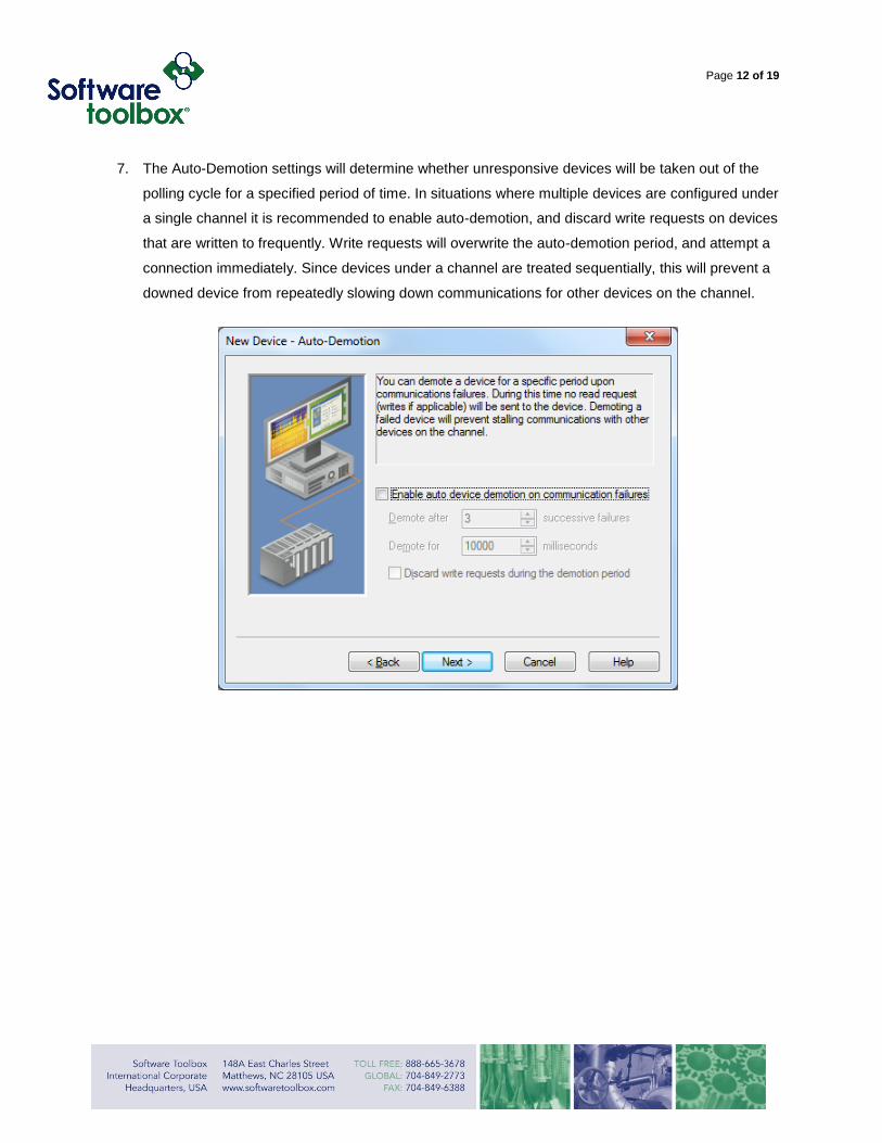
7. The Auto-Demotion settings will determine whether unresponsive devices will be taken out of the
polling cycle for a specified period of time. In situations where multiple devices are configured under
a single channel it is recommended to enable auto-demotion, and discard write requests on devices
that are written to frequently. Write requests will overwrite the auto-demotion period, and attempt a
connection immediately. Since devices under a channel are treated sequentially, this will prevent a
downed device from repeatedly slowing down communications for other devices on the channel.
Page 13 of 19
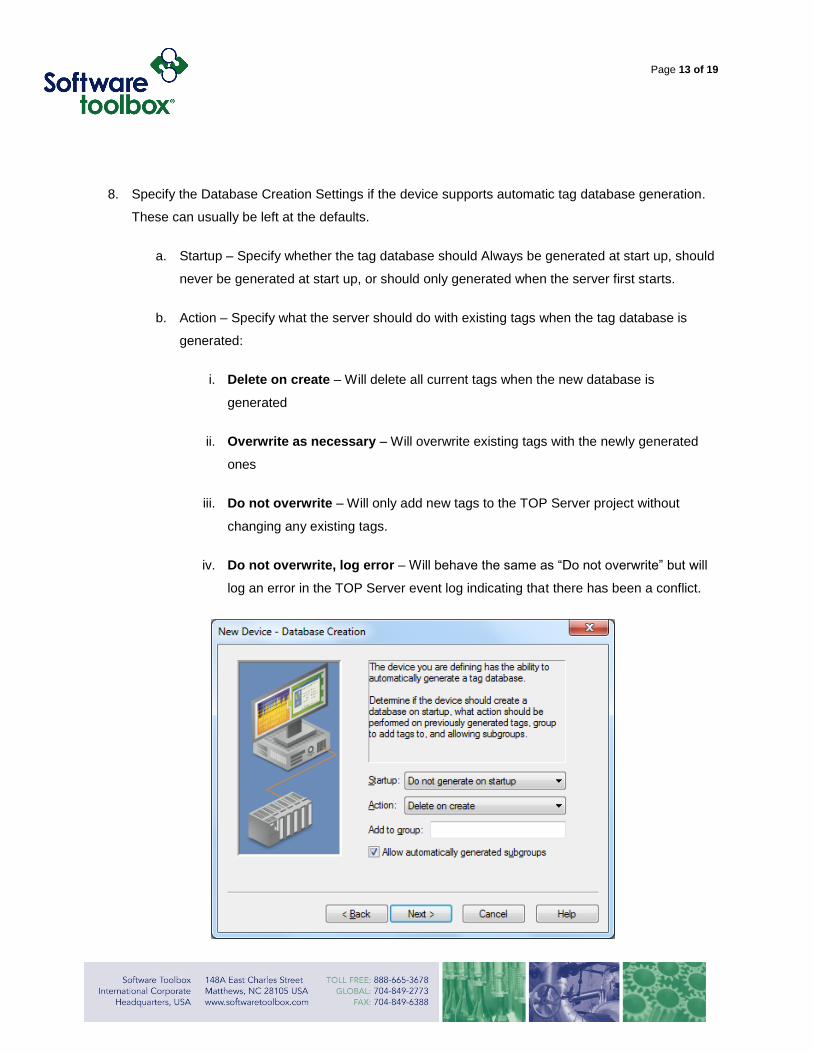
8. Specify the Database Creation Settings if the device supports automatic tag database generation.
These can usually be left at the defaults.
a. Startup – Specify whether the tag database should Always be generated at start up, should
never be generated at start up, or should only generated when the server first starts.
b. Action – Specify what the server should do with existing tags when the tag database is
generated:
i. Delete on create – Will delete all current tags when the new database is
generated
ii. Overwrite as necessary – Will overwrite existing tags with the newly generated
ones
iii. Do not overwrite – Will only add new tags to the TOP Server project without
changing any existing tags.
iv. Do not overwrite, log error – Will behave the same as “Do not overwrite” but will
log an error in the TOP Server event log indicating that there has been a conflict.
Page 14 of 19
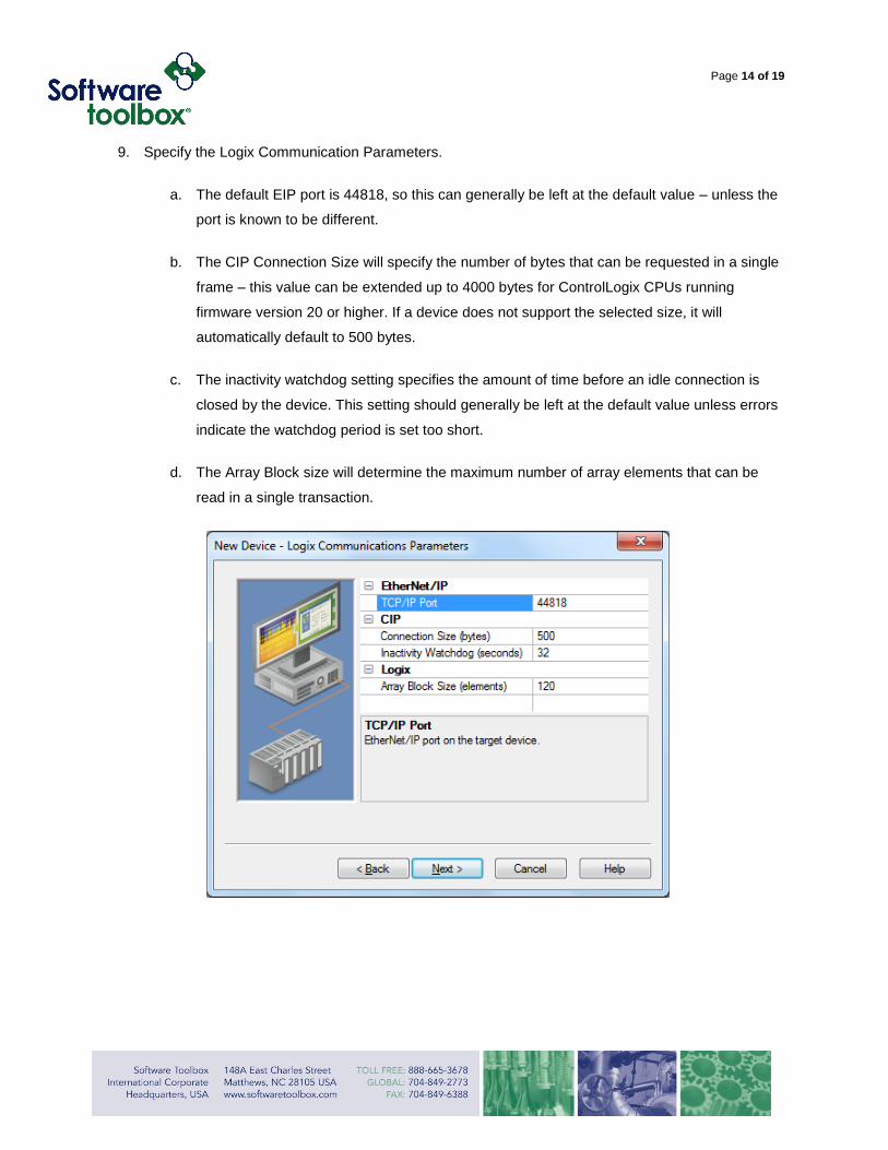
9. Specify the Logix Communication Parameters.
a. The default EIP port is 44818, so this can generally be left at the default value – unless the
port is known to be different.
b. The CIP Connection Size will specify the number of bytes that can be requested in a single
frame – this value can be extended up to 4000 bytes for ControlLogix CPUs running
firmware version 20 or higher. If a device does not support the selected size, it will
automatically default to 500 bytes.
c. The inactivity watchdog setting specifies the amount of time before an idle connection is
closed by the device. This setting should generally be left at the default value unless errors
indicate the watchdog period is set too short.
d. The Array Block size will determine the maximum number of array elements that can be
read in a single transaction.
Page 15 of 19
10. The next dialog will configure the Logix Options.
a. Protocol Mode – The protocol mode determines how TOP Server references Tags in the
controller.
i. Symbolic – The TOP server passes the fully qualified tag name to the controller,
which in turn resolves the tag name to an internal memory index. This protocol
mode generally has lower overhead and startup, but is inefficient in the long term
since the CPU will have to resolve the same Tag name every time it is written to or
read, and the 500byte packet limitations reduces the number of data points that
can be read/written in a single transaction.
Symbolic Protocol modes is recommended for systems where the TOP Server will
be restarted frequently, where only a small fraction of the total tags are being
requested, or when multiple ControlLogix controllers must be configured under a
single channel.
ii. Logical – This protocol mode is unique to the TOP Server. On initial connection the
TOP Server will map out the entirety of the ControlLogix address map; this allows
TOP server to pass the memory index to the CPU rather than the fully defined tag
name. While the initial overhead is much higher than Symbolic protocol mode,
communication rate is much faster in the long term.
Logical protocol modes are recommended in systems where a large number of
tags are being read from the controller, and when the TOP Server will be left
running for long periods of time without restart. The Logical Protocol comes with
two classifications:
Blocking – Will read entire data structures of tags being requested, and is
recommended for projects where more than 50% of arrays/structures are being
read from the controller.
Non-Blocking – Will request individual memory addresses and not read entire
arrays. This mode is recommended when less than 50% of data structures are
being requested from the controller.

Page 16 of 19
The various Protocol modes create a unique optimization opportunity with the ControlLogix
Ethernet driver – multiple connections can be made to the controller using different
protocols, to maximize data throughput.
Note: Logical protocol modes should never be used when multiple ControlLogix have to be
(this is not recommended) configured under a single channel.
b. Synchronization settings – This option is available when a logical protocol mode is
selected, and controls whether the TOP server should rebuild the Address Map when
online/offline project changes are detected. It is recommended to keep these enabled to
make sure that TOP Server is using accurate memory addresses.
c. Automatically read string length – When enabled, the serer will automatically read the
LEN field for any String Structures when the DATA memer is read. The Data String is then
terminated whenever a NUL Character is encountered, or the string length is met –
whichever occurs first.
d. Default Data Type – Specifies the data type assigned to a tag when the default type is
selected during tag addition, modification, or import. When Default is selected the driver
retrieves the tag’s data type from the controller. It is recommended to set this to a type if
the majority of
e. Enable Performance Statistics - When enabled the driver will gather communication
statistics to help determine the driver's performance. Once a project configuration is
designed for optimal performance it is recommended that this setting be disabled.

Page 17 of 19
11. Specify how the tags will be auto-generated, if the tags will be auto generated. The TOP server
supports importing the tag database directly from the controller, or by importing the tag database
from a L5K project file.

Page 18 of 19
12. Verify that the device settings are correct, and select finish to create the configured device and add
it to the channel.
13. Tags can now be statically added or dynamically addressed from client application.
14. In order to now auto-generate the Controller’s tag database connect to the Runtime – if not already
connected – and right click on the Device and open the device properties.

Page 19 of 19
15. Navigate to the Database Creation tab and use the Auto Create button to begin the automatic tag
generation.
16. The TOP Server event log will indicate when the generation is complete, if it has completed
successfully, and how many tags were auto-generated.
Further Information
This guide is intended to server as a quick, step-by-step, guide on configuring an Allen Bradley
ControlLogix Ethernet device use the TOP Server v5. It is not intended to be a comprehensive ‘how-to’
guide regarding the Allen Bradley ControlLogix Ethernet driver, and the TOP Server help file should be
referenced for further information.