wonderware allen-bradley controllogix i/o server …using the status item in excel ... 6 wonderware...
TRANSCRIPT

Wonderware Allen-BradleyControlLogix I/O Server
User’s GuideRevision BJuly 2001
Wonderware Corporation

All rights reserved. No part of this documentation shall be reproduced, stored in aretrieval system, or transmitted by any means, electronic, mechanical, photocopying,recording, or otherwise, without the prior written permission of the WonderwareCorporation. No copyright or patent liability is assumed with respect to the use of theinformation contained herein. Although every precaution has been taken in thepreparation of this documentation, the publisher and author assume no responsibility forerrors or omissions. Neither is any liability assumed for damages resulting from the useof the information contained herein.
The information in this documentation is subject to change without notice and does notrepresent a commitment on the part of Wonderware Corporation. The software describedin this documentation is furnished under a license or nondisclosure agreement. Thissoftware may be used or copied only in accordance with the terms of these agreements.
Wonderware Allen-Bradley ControlLogix I/O Server User’s Guide
2001 Wonderware Corporation. All Rights Reserved.100 Technology DriveIrvine, CA 92618U.S.A.(949) 727-3200http://www.wonderware.com
TrademarksAll terms mentioned in this book that are known to be trademarks or service marks havebeen appropriately capitalized. Wonderware Corporation cannot attest to the accuracyof this information. Use of a term in this book should not be regarded as affecting thevalidity of any trademark or service mark.
Wonderware and InTouch are registered trademarks of Wonderware Corporation.
FactorySuite, Wonderware FactorySuite, WindowMaker, WindowViewer, SQL AccessManager, Recipe Manager, SPCPro, DBDump, DBLoad, HDMerge, HistData,Wonderware Logger, Alarm Logger, InControl, InTrack, InBatch, IndustrialSQL,FactoryOffice, FactoryFocus, License Viewer, SuiteLink, SuiteVoyager and NetDDE aretrademarks of Wonderware Corporation.
Microsoft, Microsoft Excel, MS-DOS, Windows, Windows NT and Windows 2000 areeigher registered trademarks or tradements of Microsoft Corporation.
Allen-Bradley, PLC, PLC-2, PLC-3, and PLC-5 are registered trademarks of Allen-BradleyCompany, Inc., A Rockwell International Company.

Data Highway, Data Highway Plus, DH, DH+, SLC 500, INTERCHANGE, and PyramidIntegrator are trademarks of Allen-Bradley Company, Inc., A Rockwell InternationalCompany.


i
Contents
Introduction ....................................................................................................................................1Communication Protocols .....................................................................................................1Accessing Remote Items via the I/O Server.......................................................................2
Getting Started Quickly with the I/O Server...............................................................................3Using Windows NT and Windows 2000............................................................................3
ABCIP Main Window....................................................................................................................4
View Menu ......................................................................................................................................4
File Menu.........................................................................................................................................5
Configuring the I/O Server............................................................................................................6
Configuring a Topic Definition ....................................................................................................7Topic Definition......................................................................................................................7ABCIP - Topic Definition......................................................................................................8
Configuring the I/O Server Settings..........................................................................................11Server Settings......................................................................................................................11
Configuring Security....................................................................................................................13Security..................................................................................................................................13
Configuring Logger......................................................................................................................14Set Logger Mode..................................................................................................................14
Data Menu.....................................................................................................................................15ABCIP - Data Monitor.........................................................................................................15Dump Active Data................................................................................................................17Dump Topic Name Database..............................................................................................18
Accessing I/O Server Help .........................................................................................................19Contents ................................................................................................................................19How to Use Help ..................................................................................................................19About ABCIP........................................................................................................................19
Unsolicited Message Handling..................................................................................................20What is an Unsolicited Message?.....................................................................................20Setting up the PLC ...............................................................................................................21Setting up the I/O Server and InTouch.............................................................................23Error Conditions Inside the PLC ........................................................................................24Comments About Unsolicited Messages.........................................................................25
ii Wonderware Allen-Bradley ControlLogix I/O Server
Item Names.................................................................................................................................... 26PLC-5 Item Naming .............................................................................................................. 26SLC-500 Item Naming .......................................................................................................... 34
Predefined Item/Point Names ..................................................................................................... 43UPDATEINTERVAL Item................................................................................................... 43MAXINTERVAL Item......................................................................................................... 43STORESETTINGS Item....................................................................................................... 44ITEMCOUNT Item............................................................................................................... 44ERRORCOUNT Item............................................................................................................ 44WRITECOMPLETE Item..................................................................................................... 45STATUS Item....................................................................................................................... 45
Monitoring the Status of Communications with a PLC.......................................................... 46Using the Status Item in Excel............................................................................................ 46
Monitoring the Status of Communications with InTouch..................................................... 46Using DDEStatus and IOStatus in Excel.......................................................................... 46
Reading Values from the I/O Server into Excel........................................................................ 47
Writing Values to the I/O Server from Excel............................................................................ 48
Troubleshooting I/O Server Communication Problems ......................................................... 49Debugging Communication Between InTouch and an I/O Server............................... 49Debugging Communication Between SuiteLink and an I/O Server.............................. 51Debugging Communication Between an I/O Server and a PLC.................................... 52
1
Wonderware Allen-BradleyControlLogix I/O Server
IntroductionThe Wonderware Allen-Bradley ControlLogix I/O Server (referred to as the serverthrough the remainder of this user’s guide) is a Microsoft Windows applicationprogram that acts as a communication protocol server. It allows other Windowsapplication programs access to data in PLCs (also referred to as devices) attached to theDH+ and ControlNet networks through the ControlLogix Gateway. The serverrequires the Rockwell Software RSLinx OEM package. It can access data in PLC-5,SLC-500 and Logix-5000 Controller (emulating PLC-5 or SLC-500) from Ethernetconnected to the ControlLogix Gateway (is this a TM?). While the server is primarilyintended for use with Wonderware InTouch (version 3.01 and later), it may be used byany Microsoft Windows program capable of acting as a DDE, FastDDE, or SuiteLink
client.
Communication ProtocolsDynamic Data Exchange (DDE) is a communication protocol developed by Microsoft toallow applications in the Windows environment to send/receive data and instructionsto/from each other. It implements a client-server relationship between two concurrentlyrunning applications. The server application provides the data and accepts requestsfrom any other application interested in its data. Requesting applications are calledclients. Some applications such as InTouch and Microsoft Excel can simultaneously beboth a client and a server.
FastDDE provides a means of packing many proprietary Wonderware DDE messagesinto a single Microsoft DDE message. This packing improves efficiency andperformance by reducing the total number of DDE transactions required between a clientand a server. Although Wonderware's FastDDE has extended the usefulness of DDE forour industry, this extension is being pushed to its performance constraints in distributedenvironments.
NetDDE extends the standard Windows DDE functionality to include communicationover local area networks and through serial ports. Network extensions are available toallow DDE links between applications running on different computers connected vianetworks or modems. For example, NetDDE supports DDE between applications runningon IBM compatible computers connected via LAN or modem and DDE-awareapplications running on non-PC based platforms under operating environments such asVMS and UNIX.
SuiteLink uses a TCP/IP based protocol and is designed specifically to meet industrialneeds such as data integrity, high-throughput, and easier diagnostics. This protocolstandard is only supported on Microsoft Windows NT 4.0 or higher and Windows 2000.
2 Wonderware Allen-Bradley ControlLogix I/O Server
SuiteLink is not a replacement for DDE, FastDDE, or NetDDE. The protocol usedbetween a client and a server depends on your network connections and configurations.SuiteLink was designed to be the industrial data network distribution standard andprovides the following features:
• Value Time Quality (VTQ) places a time stamp and quality indicator on all datavalues delivered to VTQ-aware clients.
• Extensive diagnostics of the data throughput, server loading, computer resourceconsumption, and network transport are made accessible through the MicrosoftWindows NT and Windows 2000 operating system Performance Monitor. Thisfeature is critical for the scheme and maintenance of distributed industrial networks.
• Consistent high data volumes can be maintained between applications regardless ifthe applications are on a single node or distributed over a large node count.
• The network transport protocol is TCP/IP using Microsoft’s standard WinSockinterface.
Accessing Remote Items via the I/O ServerThe communication protocol addresses an element of data in a conversation that uses athree-part naming convention that includes the application name, topic name and itemname. The following briefly describes each portion of this naming convention:
application name The name of the Windows program (server) that will be accessingthe data element. In the case of data coming from or going toAllen Bradley equipment via this server, the application portion ofthe address is ABCIP.
topic name Meaningful names are configured in the server to identify specificdevices. These names are then used as the topic name in allconversations to that device. For example, ABPLC.
Note You can define multiple topic names for the same device(PLC) to poll different points at different rates.
item name A specific data element within the specified topic. For example,when using this server, an item can be a relay, timer, counter,register, etc., in the PLC.
Note The item/point names are predefined by the server. Theterm "point" is used interchangeably with the term "item" in thisuser's guide.
$ For more information on item/point names, see the "ItemNames" section in this user's guide.
Getting Started Quickly with the I/O Server 3
Getting Started Quickly with the I/O ServerThis section briefly describes the procedure required to install and prepare theWonderware Allen-Bradley ControlLogix I/O Server for use. Detailed descriptions ofeach step can be found in the user's guide provided by Allen-Bradley and in latersections of this user's guide.
Using Windows NT and Windows 2000
1. Install the Ethernet adapter and TCP/IP software following the instructions providedby the manufacturer.
2. Install and configure the Rockwell Software RSLinx OEM package. This package isprovided by Rockwell Software, Inc.
3. Install the Wonderware Allen-Bradley ControlLogix I/O Server for Windows NT orWindows 2000 by running the SETUP.EXE program on the server program disk.
4. Reboot the computer and restart Windows NT or Windows 2000.
5. Start the server. (Select the server icon from the server’s program group.)
6. On the Configure menu, click Topic Definition to configure topics for the PLCs.
7. The server is now ready for use.
4 Wonderware Allen-Bradley ControlLogix I/O Server
ABCIP Main Window
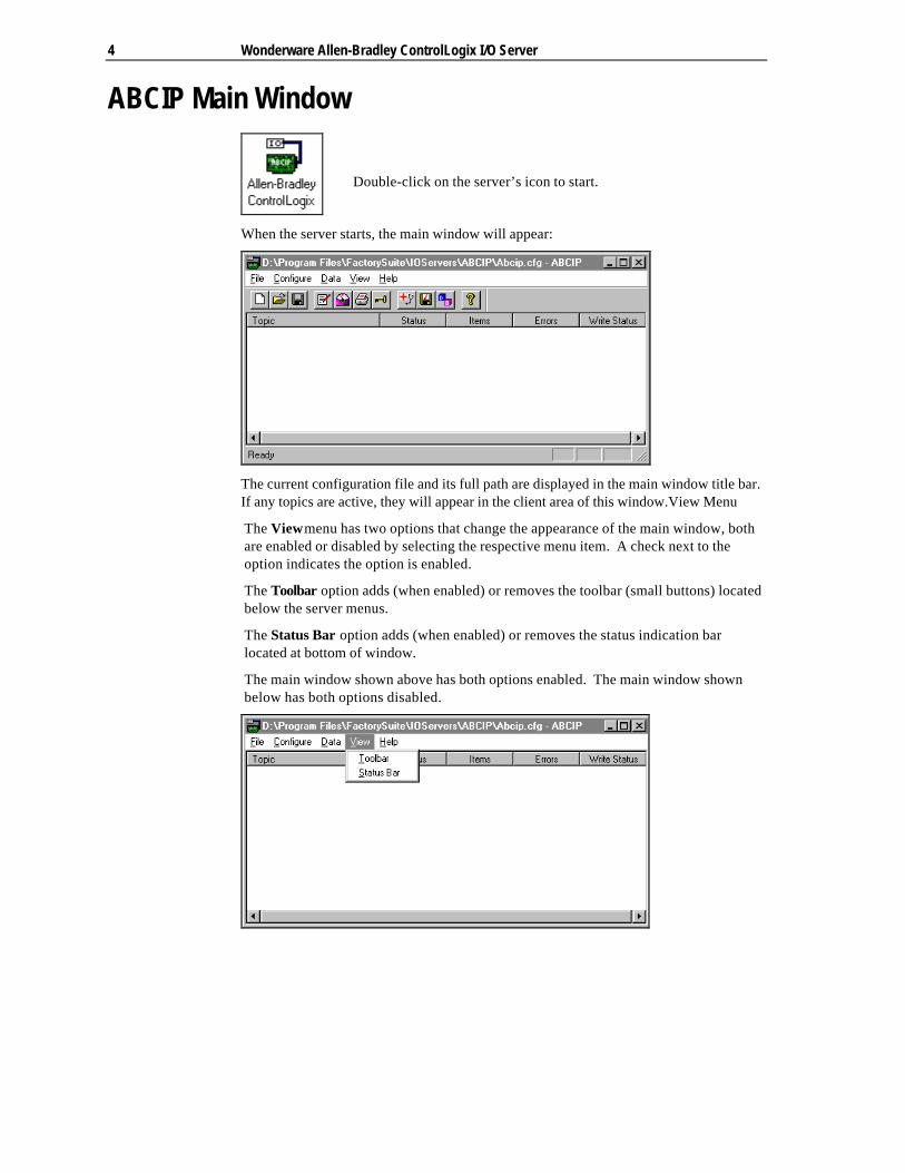
When the server starts, the main window will appear:
The current configuration file and its full path are displayed in the main window title bar.If any topics are active, they will appear in the client area of this window.View Menu
The View menu has two options that change the appearance of the main window, bothare enabled or disabled by selecting the respective menu item. A check next to theoption indicates the option is enabled.
The Toolbar option adds (when enabled) or removes the toolbar (small buttons) locatedbelow the server menus.
The Status Bar option adds (when enabled) or removes the status indication barlocated at bottom of window.
The main window shown above has both options enabled. The main window shownbelow has both options disabled.
Double-click on the server’s icon to start.
File Menu 5
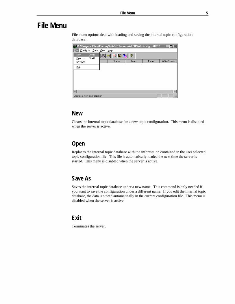
File MenuFile menu options deal with loading and saving the internal topic configurationdatabase.
NewClears the internal topic database for a new topic configuration. This menu is disabledwhen the server is active.
OpenReplaces the internal topic database with the information contained in the user selectedtopic configuration file. This file is automatically loaded the next time the server isstarted. This menu is disabled when the server is active.
Save As Saves the internal topic database under a new name. This command is only needed ifyou want to save the configuration under a different name. If you edit the internal topicdatabase, the data is stored automatically in the current configuration file. This menu isdisabled when the server is active.
Exit Terminates the server.

6 Wonderware Allen-Bradley ControlLogix I/O Server
Configuring the I/O Server Once the server has been installed, some configuration is required. Configuring theserver automatically saves the data in a configuration file. If no configuration file isselected, the user is prompted to select a filename.
To access the options used for the various configurations, open the Configure menu:
Note If any of the options appear grayed, then these options are not available with thissoftware version.

Configuring a Topic Definition 7
Configuring a Topic Definition Use the Topic Definition option from the Configure menu to create new, modify, ordelete topic definitions. One or more topic definitions must exist for each PLC that theserver will communicate with. Each topic definition must contain a unique name for thePLC associated with it. When this option is selected, the Topic Definition dialog boxwill appear:
Topic Definition
Note Once topics have been defined, their names will be listed in the Topics section ofthis dialog box.
Click this button to close the dialog box and accept any new definitions, modifications ordeletions made.
To modify or view an existing topic definition, select its name in the list and click on thisbutton. The ABCIP - Topic Definition dialog box (described below) will appeardisplaying the selected topic definition.
To delete an existing topic definition, select its name in the list and click on this button.A message box will appear prompting you to confirm the deletion.
To add a new topic definition, click on this button. The ABCIP - Topic Definition dialogbox will appear:
8 Wonderware Allen-Bradley ControlLogix I/O Server
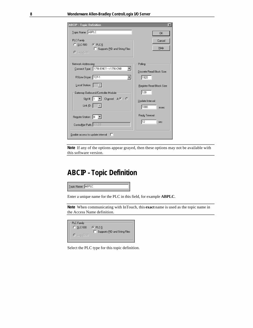
Note If any of the options appear grayed, then these options may not be available withthis software version.
ABCIP - Topic Definition
Enter a unique name for the PLC in this field, for example ABPLC.
Note When communicating with InTouch, this exact name is used as the topic name inthe Access Name definition.
Select the PLC type for this topic definition.

Configuring a Topic Definition 9
Select the Connect Type for this topic definition. Available connection types are asfollows:
1756-ENETà1756-CNB: Connect to PLCs on ControlNet from Ethernet.1756-ENETà1756-DHRIO: Connect to PLCs on DH+ from Ethernet.1756-ENETàLogix5550: Connect to Logix5550 Controller from Ethernet.Remote ControlNet: Connect to remote ControlNet port from Ethernet.
Note This connect type is similar to the 1756-ENETà1756-CNB type but allows theuser to manually construct the ControlNet path.
Select or type in the driver name configured in RSLinx for the selected Connect Type. IfRSLinx has not been loaded and the select button is pressed, the user will be promptedto load RSLinx for browsing.
Select the station number of the ControlNet module or PLC on the local ControlNetnetwork.
Configure the Gateway outbound module (for example, 1756-CNB, 1756-DHRIO) orLogix5550 Controller in the ControlLogix Gateway. Link ID is needed if the outboundnetwork is DH+ and unsolicited messages are expected.
Select the station number of the PLC on the remote network.
Enter the ControlNet Path if “Remote ControlNet” is specified as the Connect Type,otherwise this field is read only.

10 Wonderware Allen-Bradley ControlLogix I/O Server
Check this box to enable client access to the update interval. If this box is checked, aclient can read and write the update interval on this topic through the predefined itemname UPDATEINTERVAL. If this box is not checked, the client can only read theupdate interval.
Note The actual update interval for the slowest item on this topic can be read throughthe predefined item name MAXINTERVAL. This gives you an indication of theperformance of your configuration during operation.
Enter the maximum number of consecutive discrete values to be read at one time. TheDiscrete Read Block Size value can be any integer between 8 and 1920 that is a multipleof 8, for example, 8, 24, 32, 80, etc. The maximum for a SLC-500 is 320.
Enter the maximum number of consecutive registers to be read at one time. The RegisterRead Block Size value can be any integer between 1 and 120. The maximum for a SLC-500 is 40.
Enter the frequency (in milliseconds) that the server will read (poll) the items/pointsassociated with this topic. (Enter a zero in this field when configuring a topic forUnsolicited Messages, this in effect disables periodic polling.)
Note Different items/points can be polled at different rates by defining multiple topicnames for the same PLC and setting different update rates for each topic.
Enter the amount of time (in seconds) that the PLC will be given to reply to commandsfrom the server.
Note This timeout is sustained only when the PLC fails to respond. When the PLC isresponding normally, there is no penalty. The default value of 12 seconds should besufficient for most configurations.

Configuring the I/O Server Settings 11
Configuring the I/O Server Settings Use the Server Settings option from the Configure menu to change the protocol timer,network using Wonderware NetDDE, change the default configuration file path, or toenable the server to start automatically as a Windows NT or Windows 2000 service.
Note When configuring the server on Windows NT or Windows 2000, the user must belogged on with system administrator privileges. This will ensure that updates to thesystem registry may be performed.
When the Server Settings option is selected, the Server Settings dialog box will appear:
Server Settings
Enter the frequency (in milliseconds) that the server is to check for data to process. Thisshould be approximately two to four times faster than the fastest rate desired to updatedata from the equipment.
Note The default protocol timer tick value will vary between servers.
Select this option if you are networking using Wonderware NetDDE.
To create a new default configuration file, enter the complete path for the directory inwhich the file is to be saved in this field. This new path will automatically be written tothe WIN.INI file and the server will use this path to load its configuration file the nexttime it is started.

12 Wonderware Allen-Bradley ControlLogix I/O Server
Enabling this option will cause the server to start as a Windows NT or Windows 2000service.
Windows NT and Windows 2000 offers the capability of running applications evenwhen a user is not logged on to the system. This is valuable when systems mustoperate in an unattended mode. Enabling this option and rebooting the system willcause the server to run as a Windows NT or Windows 2000 service. However, to viewconfiguration information or to reconfigure the server, the user must log on to thesystem. Any server related problems that may arise such as missing adapter cards,licensing failures or device drivers not loading will not be visible to the user until a logon is performed. Disabling this option and rebooting the system will cause the server torun as a Windows NT or Windows 2000 application program once again.
Note It is highly recommended that the server is configured and communicatingsuccessfully prior to running it as a Windows NT or Windows 2000 service.
Click Cancel to close the dialog box without saving changes.
Click OK to close the dialog box.
Note You must restart the server for the changes to take effect.

Configuring Security 13
Configuring Security Use the Security option from the configure menu to control server configurationchanges.
Security When the server is not active (no clients connected), all server configuration options areavailable for modification.
The default setting for Allow configuration while topics are active is disabled. Whendisabled, all topics are viewable (but locked against changes) via the ABCIP - TopicDefinition dialog box while the server is active (a client is connected).
Enable Allow configuration while topics are active to allow write access to someparameters of the topic configuration while the server is active. This server supportswrite access to the Update Interval, Reply Timeout, and Enable Access to Update Intervalparameters. You cannot add, delete, rename or change other parameters of a topicconfiguration.
Click OK to save changes and close the dialog box.
Click Cancel to close the dialog box without saving changes.
14 Wonderware Allen-Bradley ControlLogix I/O Server
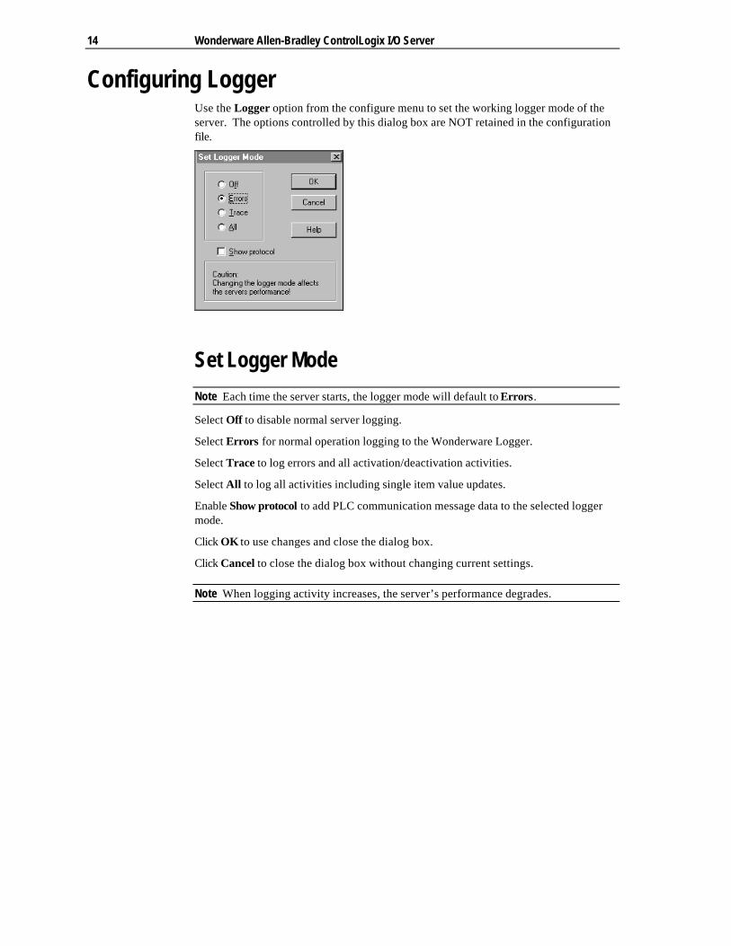
Configuring Logger Use the Logger option from the configure menu to set the working logger mode of theserver. The options controlled by this dialog box are NOT retained in the configurationfile.
Set Logger Mode
Note Each time the server starts, the logger mode will default to Errors.
Select Off to disable normal server logging.
Select Errors for normal operation logging to the Wonderware Logger.
Select Trace to log errors and all activation/deactivation activities.
Select All to log all activities including single item value updates.
Enable Show protocol to add PLC communication message data to the selected loggermode.
Click OK to use changes and close the dialog box.
Click Cancel to close the dialog box without changing current settings.
Note When logging activity increases, the server’s performance degrades.
Data Menu 15
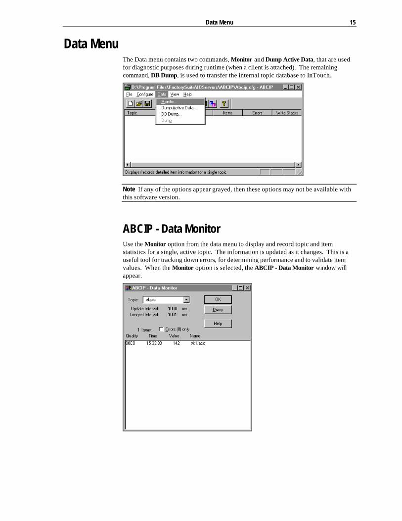
Data Menu The Data menu contains two commands, Monitor and Dump Active Data, that are usedfor diagnostic purposes during runtime (when a client is attached). The remainingcommand, DB Dump, is used to transfer the internal topic database to InTouch.
Note If any of the options appear grayed, then these options may not be available withthis software version.
ABCIP - Data Monitor Use the Monitor option from the data menu to display and record topic and itemstatistics for a single, active topic. The information is updated as it changes. This is auseful tool for tracking down errors, for determining performance and to validate itemvalues. When the Monitor option is selected, the ABCIP - Data Monitor window willappear.

16 Wonderware Allen-Bradley ControlLogix I/O Server
This drop down list box allows you to select any of the active topics. A preceding ‘*’indicates that at least one item in this topic has an error while a preceding ‘#’ indicatesbad communication status.
This field displays the current configured update interval of the topic. This valuechanges whenever the value is modified. The displayed value is the predefinedUPDATEINTERVAL item value.
This field displays the current update interval of the slowest item of the topic. Thisvalue is measured for each poll cycle and each received cyclic service indication. If thisvalue drastically differs from the desired update interval the communication media is notfast enough to satisfy the load.
Note You can create an InTouch performance meter by displaying the predefinedUPDATEINTERVAL and MAXINTERVAL (Longest Interval) item values. graphicallyfor each topic. If the topic is configured to “Enable access to update interval”, then youcan even tune the bus performance conveniently from InTouch.
This field displays the number of active items and the number of items with errors (inparenthesis). If you check this box, only items with errors will be displayed.
The item list box displays the quality, time, value, and name of each active item.
Click on an item line to view additional item properties:
Click OK to return to the ABCIP - Data Monitor dialog box.
Data Menu 17
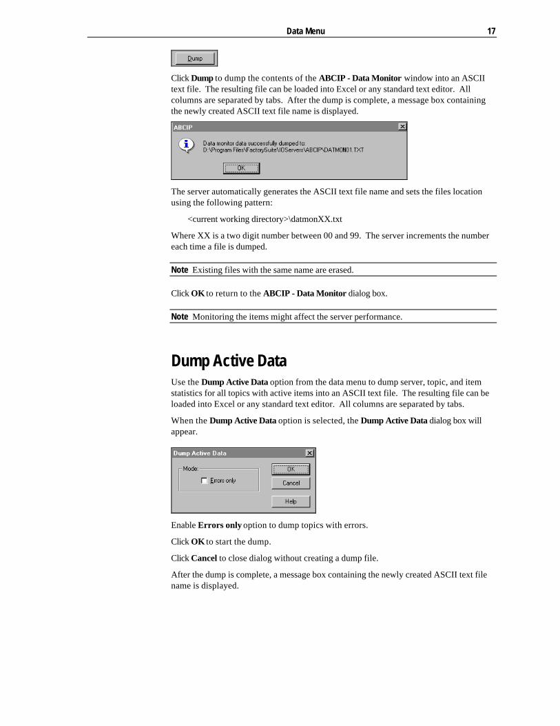
Click Dump to dump the contents of the ABCIP - Data Monitor window into an ASCIItext file. The resulting file can be loaded into Excel or any standard text editor. Allcolumns are separated by tabs. After the dump is complete, a message box containingthe newly created ASCII text file name is displayed.
The server automatically generates the ASCII text file name and sets the files locationusing the following pattern:
<current working directory>\datmonXX.txt
Where XX is a two digit number between 00 and 99. The server increments the numbereach time a file is dumped.
Note Existing files with the same name are erased.
Click OK to return to the ABCIP - Data Monitor dialog box.
Note Monitoring the items might affect the server performance.
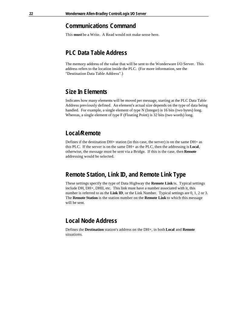
Dump Active Data Use the Dump Active Data option from the data menu to dump server, topic, and itemstatistics for all topics with active items into an ASCII text file. The resulting file can beloaded into Excel or any standard text editor. All columns are separated by tabs.
When the Dump Active Data option is selected, the Dump Active Data dialog box willappear.
Enable Errors only option to dump topics with errors.
Click OK to start the dump.
Click Cancel to close dialog without creating a dump file.
After the dump is complete, a message box containing the newly created ASCII text filename is displayed.

18 Wonderware Allen-Bradley ControlLogix I/O Server
The server automatically generates the ASCII text file name and sets the files locationusing the following pattern:
<current working directory>\datdmpXX.txt
Where XX is a two digit number between 00 and 99. The server increments the numbereach time a file is dumped.
Note Existing files with the same name are erased.
Dump Topic Name Database Use the DB Dump option from the data menu to dump the internal topic name databaseinto a CSV format file. Wonderware’s DBLoad utility can use the resulting file toautomatically generate InTouch Access Names.
Create the file by selecting a directory and filename using the standard dialog shownbelow:

Accessing I/O Server Help 19
Accessing I/O Server Help The Help menu contains three options that are used to access help for the server.
The following briefly describes the Help menu options.
Contents This option is used to display the table of contents for the Help file.
How to Use Help This option is used to access a list of basic instructions for using the Help file.
About ABCIP This option is used to access miscellaneous information regarding the server, such asthe software version, the copyright information, license information, etc.
Your FactorySuite system license information can be viewed through the license viewingutility that is launched from the About dialog box.
$ For more information on the licensing viewing utility, see your online FactorySuiteSystem Administrator’s Guide.
20 Wonderware Allen-Bradley ControlLogix I/O Server
Unsolicited Message HandlingWonderware's servers are based on the concept of polling a hardware device forinformation. This polling is driven by a need, which is expressed in the form of arequests from one or more clients. Once a particular piece of information has beenrequested by a client, the server formulates its own request and sends that request tothe hardware device. The server then waits for a response to its request. Once theinformation has been received, the server passes that information back to the client, andrepeats the process until all clients have ceased requesting information.
The rate at which the server will poll a particular device for a specific piece of informationis defined in the topic definition, inside the server, using a parameter called the UpdateInterval. When setting this parameter, there is always a trade-off between the updatespeed of the topic and the resulting decrease in system responsiveness.
Since you more than likely want very fast response, the temptation is to set the UpdateInterval to a value close to 0 milliseconds. However, if every point is polled at this rate,the entire system will suffer due to slow response time. Therefore, you shouldcompromise, and set the Update Interval to a more reasonable value. You could alsocreate multiple topics for each device, setting the Update Interval to different values,then assign different items to different topics depending on how quickly the valueschange, and how quickly you want to see an update of those changes.
An item may be very important, but change very infrequently, e.g., alarm bits. You mayrequire very fast updates of alarms when they do change, but realistically you may onlysee them change once a week, or once a day at best. Because you do not know whenthis may happen, you are forced to set the Update Interval to some small value,approaching 0 milliseconds. That is, until now!
What is an Unsolicited Message?In the world of PLCs and servers it is obvious, to even the most casual user, that a PLCwill know when a critical event has occurred before the server will have a chance to pollfor that data. Therefore, it would seem natural that if a critical event occurs, the PLCshould have the capability to inform the server immediately, without having to wait forthe server to poll it.
This is the role of an unsolicited message. Once a PLC has determined that a criticalcondition exists, it can generate a "reply" message to a poll which never occurred. Inother words, it can answer the server's question before the server has a chance to ask it.
The following Allen-Bradley processors are capable of producing unsolicited messagesthat the Wonderware I/O Servers can understand. Specifically, the PLC-5 and SLC-500.

Unsolicited Message Handling 21
Setting up the PLCThis section explains how to set up the PLC to send unsolicited messages. To illustratethe ladder logic required to perform this function, we will use the example below. Thiswas tested with a PLC 5/10 processor, connected to a Data Highway Plus with the 5/10and a S-S Technologies 5136-SD card connected to it.
Note The text and illustrations below provide you with one example of how aWonderware Allen-Bradley I/O Server and the Allen-Bradley hardware need to beconfigured to get unsolicited messages from the PLC to the server. This same concept,changed only slightly, is compatible with any of the Wonderware Allen-Bradley I/OServers.
Inside Station 02 (the PLC 5/10) the following rungs were entered:
When viewing the MSG instruction (second line, last instruction in diagram above) withthe Allen-Bradley 6200 software, the MSG instruction parameters have the followingvalues:
Parameter Select
Communications Command: PLC-5 Typed Write
PLC Data Table Address: N12:190
Size in Elements: 1
Local/Remote: Local
Remote Station: N/A
Link ID: N/A
Remote Link Type: N/A
Local Node Address: 1
Destination Data Table Address: N12:190
22 Wonderware Allen-Bradley ControlLogix I/O Server
Communications CommandThis must be a Write. A Read would not make sense here.
PLC Data Table Address
The memory address of the value that will be sent to the Wonderware I/O Server. Thisaddress refers to the location inside the PLC. (For more information, see the"Destination Data Table Address".)
Size In ElementsIndicates how many elements will be moved per message, starting at the PLC Data TableAddress previously defined. An element's actual size depends on the type of data beinghandled. For example, a single element of type N (Integer) is 16 bits (two bytes) long.Whereas, a single element of type F (Floating Point) is 32 bits (two words) long.
Local/RemoteDefines if the destination DH+ station (in this case, the server) is on the same DH+ asthis PLC. If the server is on the same DH+ as the PLC, then the addressing is Local,otherwise, the message must be sent via a Bridge. If this is the case, then Remoteaddressing would be selected.
Remote Station, Link ID, and Remote Link TypeThese settings specify the type of Data Highway the Remote Link is. Typical settingsinclude DH, DH+, DHII, etc. This link must have a number associated with it, thisnumber is referred to as the Link ID, or the Link Number. Typical settings are 0, 1, 2 or 3.The Remote Station is the station number on the Remote Link to which this messagewill be sent.
Local Node AddressDefines the Destination station's address on the DH+, in both Local and Remotesituations.

Unsolicited Message Handling 23
Destination Data Table AddressThe address into which the value defined by the PLC Data Table Address will be placed.In the case of unsolicited messages to the server, this is the address that has beenentered into the Item field of a particular Tagname inside InTouch. For example, youmay have a tag called: TankLevel with the item, N12:190. The item specified would bethe address used for this parameter. In most cases, the PLC Data Table Address and theDestination Data Table Address do not need to be the same. To reduce confusion whendebugging the system, we recommend that they be identical.
Setting up the I/O Server and InTouchThis section briefly describes how to set up the server and InTouch to acceptunsolicited messages.
The following topic was defined in the server:
Topic Name: Unsolicited_PLC2Card: SD:0PLC Station Address: 02 (Octal)Update Interval: 0
The following Access Name was defined in InTouch:
Access Name: Unsolicited_PLC2Application/Server: SS5136SDTopic: Unsolicited_PLC2Wait For Change: CheckedAdvise All Items: Checked
Note If a PLC generates an unsolicited message and the destination tagname is notadvised (active inside InTouch), the server will generate an error message. To avoidthis, create a separate Access Name with the Advise all items option enabled, andassociate only those tags that will be receiving unsolicited messages to it. By doingthis, all unsolicited message items will be advised and will receive the unsolicited data,even if the tagname is not used in a visible window.
The following tagname was defined in InTouch:
TagName: TankLevelTagType: IntegerAccessName: Unsolicited_PLC2Item: N12:190
Note If Advise only active items is checked and the tag is displayed on the screen, it willbe advised. When this occurs, the server will store that tagname as an item that needsto be polled regularly from the PLC. For example, if the update interval was set to fiveminutes (configured in the topic definition), then every five minutes the server will sendout a request for the current value of N12:190 to the PLC. The PLC will respond,returning the value inside N12:190, in our example above. This is a Normal Polling Cycle.

24 Wonderware Allen-Bradley ControlLogix I/O Server
At the same time, the PLC is constantly monitoring the value of the TankLevel, stored inregister N12:190. If this value grows larger than 128, the PLC logic will initiate the MSGinstruction. The MSG instruction will take the value of N12:190 and write it to the server.The server will see the incoming message and attempt to match the PLC station addressdefined in the server. It will also try to match the Destination Data Table Address to onethat is currently being polled for that particular PLC address. If this matching proceduresucceeds, the value of that tag will be updated with the value sent from the PLC's MSGinstruction.
Error Conditions Inside the PLCThe Allen-Bradley 1785 PLC-5 processors have a separate CPU to handle Data HighwayPlus communications. This processor works independently of the program scan. This isan advantage, since the program scan is not inhibited by lengthy Data Highway Pluscommand queues. This means that the status bits and words associated with the MSGinstruction will be updated synchronously to the program scan. If an error bit is falsewhen the program begins to scan, half way through the rungs, the bit may go high.Inside the Allen-Bradley PLC, it is important to properly handle error conditions with aMSG instruction.
If a MSG instruction's .ER bit goes high, it is advisable to stop sending MSGs for aperiod of 15 to 60 seconds. Then, send another MSG, waiting for a .DN bit beforeattempting to resume normal communication. If this is not done, the MSG instructionwill default to a "slow mode" of one MSG every 15 seconds. If these MSGs continue tobe unacknowledged by the server, there is a chance the PLC will halt communicationwith the server until the MSG instruction is reset. This is something that cannot be donefrom the Wonderware I/O Server since the PLC may no longer be communicating with it.

Unsolicited Message Handling 25
Comments About Unsolicited Messages1. In general, unsolicited messages should be used only on rare occasions, not as the
normal mode of data transmission.
2. A MSG instruction inside a PLC should never be placed in 'continuous' mode. Thiswill cause the MSG instruction to generate outgoing messages as quickly aspossible, continuously, regardless of the state of the instructions ahead of it.Therefore, even if the Bit B10:0/14 is FALSE, if the .CO bit (Continuous Bit) is set inthe MSG instruction, the MSG instruction will continue to generate messages asquickly as possible until either the processor has been placed into PROGRAMmode, or the .CO bit is toggled off.
3. Read the Allen-Bradley manual, publication 6200-6.4.11, April 1992 for moreinformation about the MSG instruction inside the 1785 PLC-5’s. Other PLC’smanuals also have specific information regarding generating a MSG instruction inthe Ladder Logic.
Note The PLC-2 was never designed to allow communication on the DH. It has acommunications module, the 1771-KA2, which allows the PLC-2 to sit on the DH.The PLC-2 manual therefore has no mention of the messaging capabilities of thePLC-2. The manual for the 1771-KA2 has all the information you’ll need to set up anunsolicited message from the PLC-2.
4. If a PLC generates an unsolicited message and the destination tagname is notadvised (active inside InTouch), the server will generate an error message. To avoidthis, create a separate Access Name with the Advise all items option enabled, andassociate only those tagnames that will be receiving unsolicited messages. Bydoing this, all items will be advised and will receive the unsolicited data, even if thetagname is not used in a visible window.
26 Wonderware Allen-Bradley ControlLogix I/O Server
Item NamesThe Wonderware Allen-Bradley ControlLogix I/O Server supports item names that followthe conventions described for PLC-5 and SLC-500 PLCs.
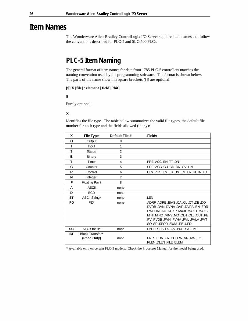
PLC-5 Item NamingThe general format of item names for data from 1785 PLC-5 controllers matches thenaming convention used by the programming software. The format is shown below.The parts of the name shown in square brackets ([]) are optional.
[$] X [file] : element [.field] [/bit]
$
Purely optional.
X
Identifies the file type. The table below summarizes the valid file types, the default filenumber for each type and the fields allowed (if any):
X File Type Default File # .FieldsO Output 0
I Input 1
S Status 2
B Binary 3
T Timer 4 .PRE .ACC .EN .TT .DN
C Counter 5 .PRE .ACC .CU .CD .DN .OV .UN
R Control 6 .LEN .POS .EN .EU .DN .EM .ER .UL .IN .FD
N Integer 7
F Floating Point 8
A ASCII none
D BCD noneST ASCII String* none .LENPD PID* none .ADRF .ADRE .BIAS .CA .CL .CT .DB .DO
.DVDB .DVN .DVNA .DVP .DVPA .EN .ERR
.EWD .INI .KD .KI .KP .MAXI .MAXO .MAXS
.MINI .MINO .MINS .MO .OLH .OLL .OUT .PE
.PV .PVDB .PVH .PVHA .PVL .PVLA .PVT
.SO .SP .SPOR .SWM .TIE .UPD
SC SFC Status* none .DN .ER .FS .LS .OV .PRE .SA .TIMBT Block Transfer*
(Read Only) none .EN .ST .DN .ER .CO .EW .NR .RW .TO.RLEN .DLEN .FILE .ELEM
* Available only on certain PLC-5 models. Check the Processor Manual for the model being used.

Item Names 27
file
File number (0-999 decimal). File 0 must be Output, file 1 must be Input and file 2 must beStatus.
element
Element number within the file. For Input and Output files it must be between 0 and 777octal. For all other file types, it must be between 0 and 999 decimal.
.field
Valid only for Counter, Timer, Control, ASCII String, PID, SFC Status, and Block Transferfiles. Refer to the previous table.
/bit
Valid for all file types except ASCII String and Floating Point. For Input and Output filesit must be between 0 and 17 octal. For all other file types it must be between 0 and 15decimal.
Output File ItemsO[n]:rg[/b] "n" represents the file number is optional and if specified, must be
zero.
"r" indicates the rack number (octal).
"g" indicates the I/O group (octal).
"b" specifies the bit (0 - 17 octal). "/b" may be omitted ifnecessary to treat the I/O group as a numeric value.
Examples:O0:0/0$O:37/17O:3 4BCD (for 16-bit 7-segment display)
Input File ItemsI[n]:rg[/b] "n" represents the file number is optional and, if specified, must
be one."r" indicates the rack number (octal)."g" indicates the I/O group (octal)."b" specifies the bit (0 - 17 octal). "/b" may be omitted ifnecessary to treat the I/O group as a numeric value.
Examples:
I1:0/0I:37/17I:3 4BCD (for 16-bit thumbwheel input)

28 Wonderware Allen-Bradley ControlLogix I/O Server
Status File ItemsS[n]:e[/b] "n" represents the file number is optional and, if specified, must
be two.
"e" indicates the element number in the file.
"b" is optional. If specified, indicates the bit (0-15 decimal).
Note Refer to the 1785 PLC-5 Family Processor Manual (Allen-Bradley Publication 1785-6.8.2) for a complete description ofstatus file information.
Examples:$S:18 low status bit)
Binary File ItemsB[n]:e/b
or
B[n]/m 2 may be between 0 and 15999.
Examples:
B3/15999 (same bit as B:999/15)B:6/4 (same bit as B/100)
Timer File ItemsT[n]:e[.f][/b] "n" represents the file number and is optional. If not specified, it
is assumed to be four. If specified, the file number must bebetween 3 and 999 decimal.
"e" specifies the element number (three words per element) withinthe Timer file. It must be between 0 and 999 decimal.
"f" identifies one of the valid Timer fields. The valid fields forTimer Files are listed in the table. If ".f" is omitted, it is assumed tobe the word containing the status bits.
"b" is optional and is normally not used. All of the fields of atimer can be accessed by specifying the ".f" fields. However, it ispossible to use "/b" to single out a bit in the .PRE or .ACC fields(which are words). For Timer files, the bit number must bebetween 0 and 15 decimal.
Examples:
T4:0.ACCT4:0.DNT4:1.PRE
Item Names 29
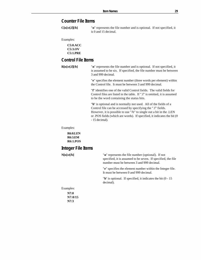
Counter File ItemsC[n]:e[.f][/b] "n" represents the file number and is optional. If not specified, it
is 0 and 15 decimal.
Examples:
C5:0.ACCC5:3.OVC5:1.PRE
Control File ItemsR[n]:e[.f][/b] "n" represents the file number and is optional. If not specified, it
is assumed to be six. If specified, the file number must be between3 and 999 decimal.
"e" specifies the element number (three words per element) withinthe Control file. It must be between 3 and 999 decimal.
"f" identifies one of the valid Control fields. The valid fields forControl files are listed in the table. If ".f" is omitted, it is assumedto be the word containing the status bits.
"b" is optional and is normally not used. All of the fields of aControl file can be accessed by specifying the ".f" fields.However, it is possible to use "/b" to single out a bit in the .LENor .POS fields (which are words). If specified, it indicates the bit (0- 15 decimal).
Examples:
R6:0.LENR6:3.EMR6:1.POS
Integer File ItemsN[n]:e[/b] "n" represents the file number (optional). If not
specified, it is assumed to be seven. If specified, the filenumber must be between 3 and 999 decimal.
"e" specifies the element number within the Integer file.It must be between 0 and 999 decimal.
"b" is optional. If specified, it indicates the bit (0 - 15decimal).
Examples:
N7:0N7:0/15N7:3
30 Wonderware Allen-Bradley ControlLogix I/O Server
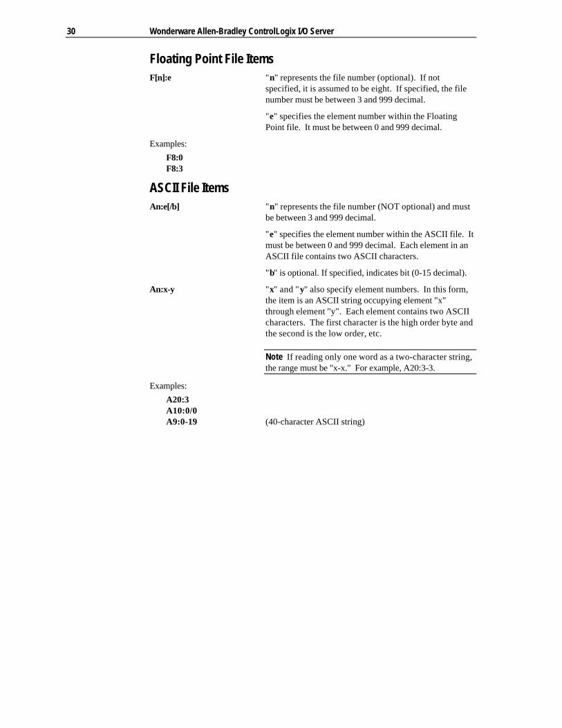
Floating Point File ItemsF[n]:e "n" represents the file number (optional). If not
specified, it is assumed to be eight. If specified, the filenumber must be between 3 and 999 decimal.
"e" specifies the element number within the FloatingPoint file. It must be between 0 and 999 decimal.
Examples:
F8:0F8:3
ASCII File ItemsAn:e[/b] "n" represents the file number (NOT optional) and must
be between 3 and 999 decimal.
"e" specifies the element number within the ASCII file. Itmust be between 0 and 999 decimal. Each element in anASCII file contains two ASCII characters.
"b" is optional. If specified, indicates bit (0-15 decimal).
An:x-y "x" and "y" also specify element numbers. In this form,the item is an ASCII string occupying element "x"through element "y". Each element contains two ASCIIcharacters. The first character is the high order byte andthe second is the low order, etc.
Note If reading only one word as a two-character string,the range must be "x-x." For example, A20:3-3.
Examples:
A20:3A10:0/0A9:0-19 (40-character ASCII string)

Item Names 31
BCD File ItemsDn:e[/b] "n" represents the file number (NOT optional) and must
be between 3 and 999 decimal.
"e" specifies the element number within the BCD file. Itmust be between 0 and 999 decimal. Each element in aBCD file contains a number between 0 and 9999.
"b" is optional. If specified, it indicates the bit (0 - 15decimal).
Examples:
D20:3D10:0/3
ASCII String Section ItemsSTn:e[.f]
"n" represents the file number (NOT optional) and mustbe between 9 and 999 decimal.
"e" specifies the element number within the String file. Itmust be between 0 and 999 decimal. Each element in aString file contains an ASCII string with a maximumlength of 82 characters.
"f" identifies the following ASCII string field: .LEN. If".f" is omitted, it is assumed to be the string.
Examples:
ST9:0ST9:900ST9:900.LEN

32 Wonderware Allen-Bradley ControlLogix I/O Server
Block Transfer Section ItemsBTn:e[.f][/b]
"n" represents the file number (NOT optional) and mustbe between 9 and 999 decimal.
"e" specifies the element number (three words perelement) within the Block Transfer file (0 to 999 decimal).
"f" identifies one of the valid Block Transfer fields. Thevalid fields for Block Transfer items are listed in the table.If ".f" is omitted, it is assumed to be the word containingthe status bits.
"b" is optional and is normally not used. All of the fieldsof a Block Transfer can be accessed by specifying the".f" fields. However, it is possible to use "/b" to singleout a bit in the .FILE or .ELEM fields (which are words).For Block Transfer files, the bit number must be between0 and 15 decimal.
Note Block Transfer files are read only.
Examples:
BT9:0.ENBT9:3.RLENBT9:3.FILE

Item Names 33
PID Section ItemsPDn:e[.f][/b]
"n" represents the file number (NOT optional) and mustbe between 9 and 999 decimal.
"e" specifies the element number within the PID file. Itmust be between 0 and 999 decimal.
"f" identifies one of the valid PID fields. The valid fieldsfor PID files are listed in the table. If PID field .ADDR isneeded, use .ADRE for element and .ADRF for file.
"b" is optional and is normally not used. All of the fieldsof a PID can be accessed by specifying the ".f" fields. Ifspecified, it indicates the bit (0 - 15 decimal).
Warning Access to PID files may degrade the server'sperformance due to the extreme size of the PID element(82 words each). If accessing only a few PIDs at a time,performance will not be greatly affected. If accessing afew fields of many PIDs at once, it may be faster to movethe needed fields to an intermediate file (Floating Point orBinary) and let the server access the intermediate files.
Examples:
PD9:2.SPPD9:3.OLHPD9:0.INI
SFC Status Section ItemsSCn:e[.f][/b]
"n" represents the file number (NOT optional) and mustbe between 5 and 999 decimal.
"e" specifies the element number within the SFC Statusfile. It must be between 0 and 999 decimal.
"f" identifies one of the valid SFC fields. The valid fieldsfor SFC files are listed in the table.
"b" is optional and is normally not used. All of the fieldsof a SFC can be accessed by specifying the ".f" fields.For SFC Status items, the bit number must be between 0and 15 decimal.
Examples:
SC9:0SC9:0.PRESC9:0.SA
34 Wonderware Allen-Bradley ControlLogix I/O Server
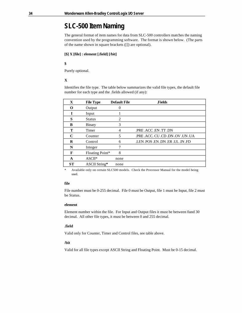
SLC-500 Item NamingThe general format of item names for data from SLC-500 controllers matches the namingconvention used by the programming software. The format is shown below. (The partsof the name shown in square brackets ([]) are optional).
[$] X [file] : element [.field] [/bit]
$
Purely optional.
X
Identifies the file type. The table below summarizes the valid file types, the default filenumber for each type and the .fields allowed (if any):
X File Type Default File .FieldsO Output 0I Input 1S Status 2B Binary 3T Timer 4 .PRE .ACC .EN .TT .DNC Counter 5 .PRE .ACC. CU .CD .DN .OV .UN .UAR Control 6 .LEN .POS .EN .DN .ER .UL .IN .FDN Integer 7F Floating Point* 8A ASCII* noneST ASCII String* none
* Available only on certain SLC500 models. Check the Processor Manual for the model beingused.
file
File number must be 0-255 decimal. File 0 must be Output, file 1 must be Input, file 2 mustbe Status.
element
Element number within the file. For Input and Output files it must be between 0and 30decimal. All other file types, it must be between 0 and 255 decimal.
.field
Valid only for Counter, Timer and Control files, see table above.
/bit
Valid for all file types except ASCII String and Floating Point. Must be 0-15 decimal.
Item Names 35
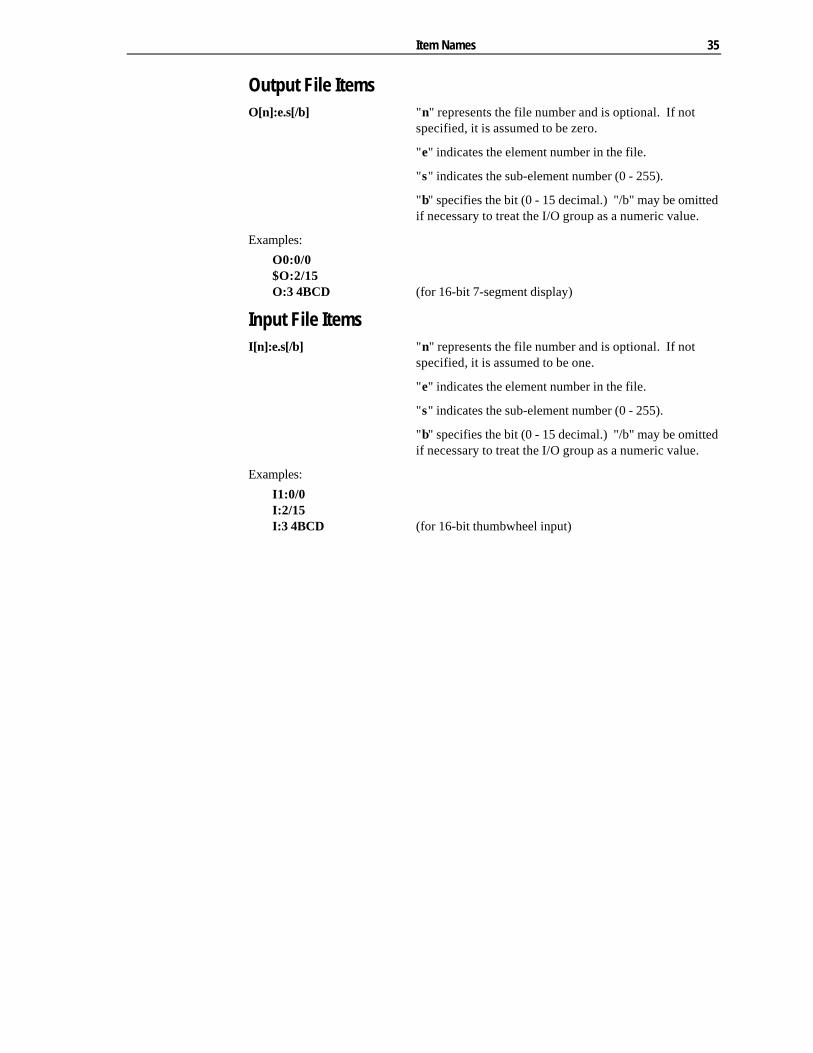
Output File ItemsO[n]:e.s[/b] "n" represents the file number and is optional. If not
specified, it is assumed to be zero.
"e" indicates the element number in the file.
"s" indicates the sub-element number (0 - 255).
"b" specifies the bit (0 - 15 decimal.) "/b" may be omittedif necessary to treat the I/O group as a numeric value.
Examples:
O0:0/0$O:2/15O:3 4BCD (for 16-bit 7-segment display)
Input File ItemsI[n]:e.s[/b] "n" represents the file number and is optional. If not
specified, it is assumed to be one.
"e" indicates the element number in the file.
"s" indicates the sub-element number (0 - 255).
"b" specifies the bit (0 - 15 decimal.) "/b" may be omittedif necessary to treat the I/O group as a numeric value.
Examples:
I1:0/0I:2/15I:3 4BCD (for 16-bit thumbwheel input)

36 Wonderware Allen-Bradley ControlLogix I/O Server
Addressing SLC I/O ModulesThe elements (words) in I/O modules are mapped into a memory table. If the Analog I/Omodules are being used, then the point naming will differ from the point naming in theprogramming software. The server item name must be computed from the sum total ofwords used by the previous input or output blocks. The operator can use theprogramming software to look at the memory map of the I file or O file to verify youraddress. If the address is unsure, or if the PLC configuration is likely to change, copythe points in question to the N table or B table and access the data from there.
The naming conventions used in the Allen-Bradley programming software are notsupported by the Wonderware Allen-Bradley ControlLogix I/O Server. The addressingconvention is similar to that of the PLC-5 family processors. To derive the correctaddress for each I/O point, use the following.
Diagram systemAddressing of the I/O points begins by drawing a schematic of the system. The figurebelow is a diagram of the SLC 5/02 system.
The far left unit is the power supply. From left to right, the modules are:
1747-L524 SLC 5/02 Module Processor
1746-IA8 8 point 120VAC input module
1746-OA16 16 Point 120VAC output module
1746-IA16 16 point 120VAC input module
1746-NI4 4 point 20mA analog input module
1746-NO4I 4 point 20mA analog output module
1746-0A8 8 point 120VAC input module
1746-IB32 32 point DC input module

Item Names 37
Label I/O modules with "word counts"The address of any point within the I/O datatable space, in a SLC processor, is the sumof the words occupied by previous modules (to the left in the rack) of the same type.Therefore, to determine the correct address for any particular point in the I/O datatable,one must know the number of words each module will consume. Refer to the list below:
Number of Words Module
0 1747-L524 SLC 5/02 Module Processor
1 1746-IA8 8 point 120VAC input module
1 1746-OA16 16 Point 120VAC output module
1 1746-IA16 16 point 120VAC input module
4 1746-NI4 4 point 20mA analog input module
4 1746-NO4I 4 point 20mA analog output module
1 1746-0A8 8 point 120VAC input module
2 1746-IB32 32 point DC input module
Note In the table above, the minimum amount of words which can be consumed by amodule is 1 (16-bits). This is due to the memory scheme of all Allen-Bradley processors.
38 Wonderware Allen-Bradley ControlLogix I/O Server
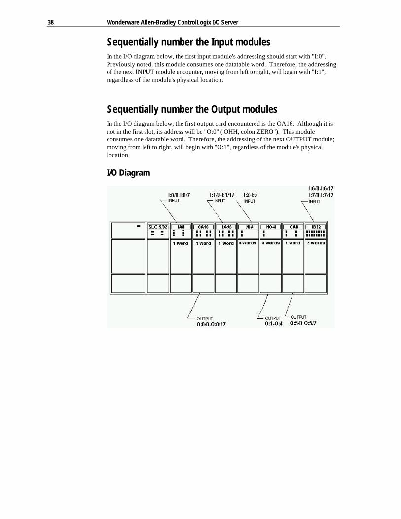
Sequentially number the Input modulesIn the I/O diagram below, the first input module's addressing should start with "I:0".Previously noted, this module consumes one datatable word. Therefore, the addressingof the next INPUT module encounter, moving from left to right, will begin with "I:1",regardless of the module's physical location.
Sequentially number the Output modulesIn the I/O diagram below, the first output card encountered is the OA16. Although it isnot in the first slot, its address will be "O:0" ('OHH, colon ZERO"). This moduleconsumes one datatable word. Therefore, the addressing of the next OUTPUT module;moving from left to right, will begin with "O:1", regardless of the module's physicallocation.
I/O Diagram

Item Names 39
Status File ItemsS[n]:e[/b] "n" represents the file number and is optional. If not
specified, it is assumed to be two.
"e" indicates the element number in the file
"b" is optional. If specified, it indicates the bit (0 - 15decimal).
Note Refer to the SLC-500 Family Processor Manual(Allen-Bradley Publication) for a complete description ofStatus file information.
Examples:
S2:6 (major error fault)S2:13 (math register)S:1/5 (forces enabled)
Binary File ItemsB[n]:e/b
or
B[n]/m "n" represents the file number and is optional. If notspecified, it is assumed to be three. If specified, the filenumber must be between 10 and 255 decimal.
"e" specifies the element (word) number within theBinary file. It must be between 0 and 255 decimal.
"b" specifies the bit number within the word. In the firstform (where ":e" is present,) the bit number must bebetween 0 and 15 decimal.
"m" also represents the bit number. However, in thesecond form, no word number is specified and the bitnumber may be between 0 and 4095.
Examples:
B3/4095 (same bit as B:255/15)B:6/4 (same bit as B/100)B3

40 Wonderware Allen-Bradley ControlLogix I/O Server
Timer File ItemsT[n]:e[.f][/b] "n" represents the file number and is optional. If not
specified, it is assumed to be four. If specified, the filenumber must be between 3 and 255 decimal.
"e" specifies the element number (three words perelement) within the Timer file. It must be between 0 and255 decimal.
"f" identifies one of the valid Timer fields. The validfields for Timer Files are listed in the table. If "f" isomitted, it is assumed to be the word containing thestatus bits.
"b" is optional and is normally not used. All of the fieldsof a timer can be accessed by specifying the ".f" fields.However, it is possible to use "/b" to single out a bit inthe .PRE or .ACC fields (which are words).
Examples:
T4:0.ACCT4:3.DNT4:1.PRE
Counter File ItemsC[n]:e[.f][/b] "n" represents the file number and is optional. If not
specified, it is assumed to be five. If specified, the filenumber must be between 3 and 255 decimal.
"e" specifies the element number (three words perelement) within the Counter file. It must be between 0and 255 decimal.
"f" identifies one of the valid Counter fields. The validfields for the Counter Files are listed in the table. If "f" isomitted, it is assumed to be the word containing thestatus bits.
"b" is optional and is normally not used. All of the fieldsof a counter can be accessed by specifying the ".f"fields. However, it is possible to use "/b" to single out abit in the .PRE or .ACC fields (which are words).
Examples:
C5:0.ACCC5:3.OVC5:1.PRE

Item Names 41
Control File ItemsR[n]:e[.f][/b] "n" represents the file number and is optional. If not
specified, it is assumed to be six. If specified, the filenumber must be between 3 and 255 decimal.
"e" specifies the element number (three words perelement) within the Control file. It must be between 0and 255 decimal.
"f" identifies one of the valid Control fields. The validfields for the Control files are listed in the table. If "f" isomitted, it is assumed to be the word containing thestatus bits.
"b" is optional and is normally not used. All of the fieldsof a Control file can be accessed by specifying the ".f"fields. However, it is possible to use "/b" to single out abit in the .LEN or .POS fields (which are words).
Examples:
R6:0.LENR6:3.ENR6:1.POS
Integer File ItemsN[n]:e[/b] "n" represents the file number and is optional. If not
specified, it is assumed to be seven. If specified, the filenumber must be between 3 and 255 decimal.
"e" specifies the element number within the Integer file.It must be between 0 and 255 decimal.
"b" is optional. If specified, it indicates the bit (0 - 15decimal).
Examples:
N7:0N7:0/15N7:3
Floating Point File ItemsF[n]:e "n" represents the file number and is optional. If not
specified, it is assumed to be eight. If specified, the filenumber must be between 3 and 255 decimal.
"e" specifies the element number within the FloatingPoint file. It must be between 0 and 255 decimal.
Examples:
F8:0F8:3

42 Wonderware Allen-Bradley ControlLogix I/O Server
ASCII File ItemsAn:e[/b] "n" represents the file number (NOT optional).
"e" specifies the element number within the ASCII file. Itmust be between 0 and 255 decimal. Each element in anASCII file contains two ASCII characters.
"b" is optional. If specified, indicates bit (0-15 decimal).
Examples:
A20:3A10:0/0
ASCII String Section ItemsSTn:e
"n" represents the file number (NOT optional).
"e" specifies the element number within the String file. Itmust be between 0 and 255 decimal. Each element in aString file contains an ASCII string with a maximumlength of 78 characters.
Examples:
ST9:0ST9:900
Predefined Item/Point Names 43
Predefined Item/Point Names All topics have predefined item/point names to monitor and control communicationproperties.
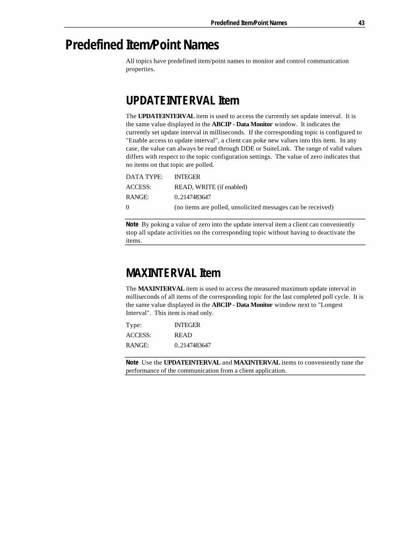
UPDATEINTERVAL Item The UPDATEINTERVAL item is used to access the currently set update interval. It isthe same value displayed in the ABCIP - Data Monitor window. It indicates thecurrently set update interval in milliseconds. If the corresponding topic is configured to"Enable access to update interval", a client can poke new values into this item. In anycase, the value can always be read through DDE or SuiteLink. The range of valid valuesdiffers with respect to the topic configuration settings. The value of zero indicates thatno items on that topic are polled.
DATA TYPE: INTEGER
ACCESS: READ, WRITE (if enabled)
RANGE: 0..2147483647
0 (no items are polled, unsolicited messages can be received)
Note By poking a value of zero into the update interval item a client can convenientlystop all update activities on the corresponding topic without having to deactivate theitems.
MAXINTERVAL Item The MAXINTERVAL item is used to access the measured maximum update interval inmilliseconds of all items of the corresponding topic for the last completed poll cycle. It isthe same value displayed in the ABCIP - Data Monitor window next to "LongestInterval". This item is read only.
Type: INTEGER
ACCESS: READ
RANGE: 0..2147483647
Note Use the UPDATEINTERVAL and MAXINTERVAL items to conveniently tune theperformance of the communication from a client application.
44 Wonderware Allen-Bradley ControlLogix I/O Server
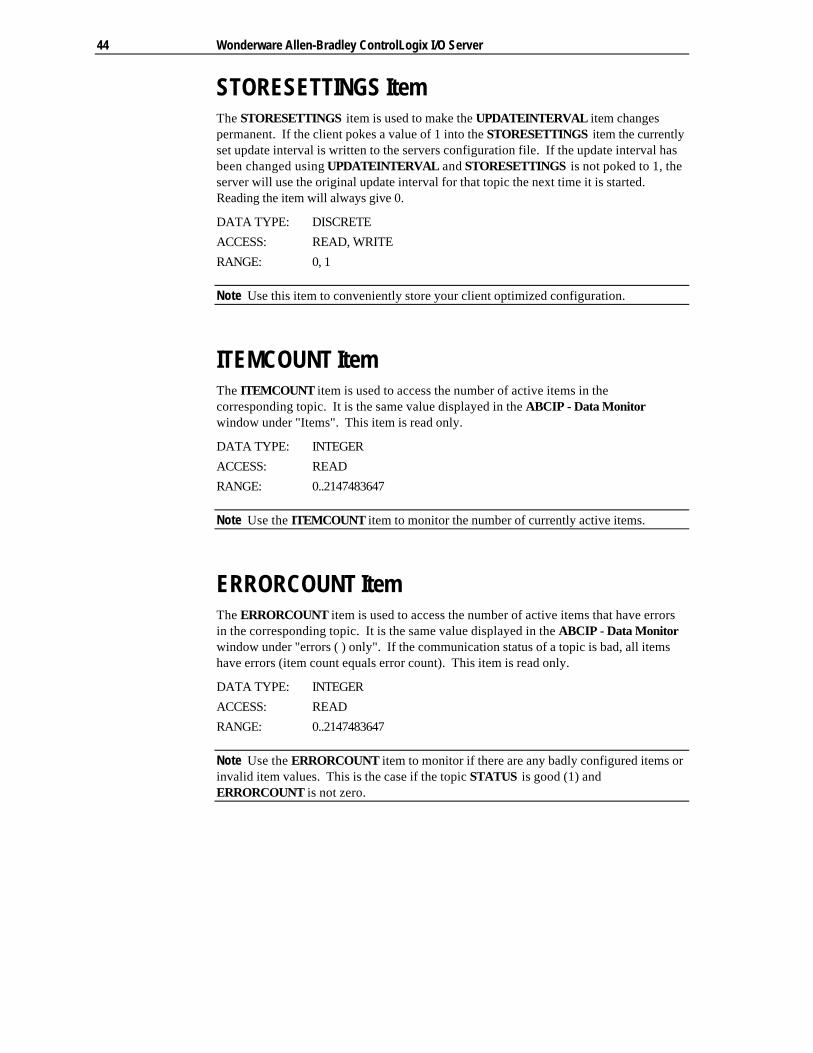
STORESETTINGS Item The STORESETTINGS item is used to make the UPDATEINTERVAL item changespermanent. If the client pokes a value of 1 into the STORESETTINGS item the currentlyset update interval is written to the servers configuration file. If the update interval hasbeen changed using UPDATEINTERVAL and STORESETTINGS is not poked to 1, theserver will use the original update interval for that topic the next time it is started.Reading the item will always give 0.
DATA TYPE: DISCRETE
ACCESS: READ, WRITE
RANGE: 0, 1
Note Use this item to conveniently store your client optimized configuration.
ITEMCOUNT Item The ITEMCOUNT item is used to access the number of active items in thecorresponding topic. It is the same value displayed in the ABCIP - Data Monitorwindow under "Items". This item is read only.
DATA TYPE: INTEGER
ACCESS: READ
RANGE: 0..2147483647
Note Use the ITEMCOUNT item to monitor the number of currently active items.
ERRORCOUNT Item The ERRORCOUNT item is used to access the number of active items that have errorsin the corresponding topic. It is the same value displayed in the ABCIP - Data Monitorwindow under "errors ( ) only". If the communication status of a topic is bad, all itemshave errors (item count equals error count). This item is read only.
DATA TYPE: INTEGER
ACCESS: READ
RANGE: 0..2147483647
Note Use the ERRORCOUNT item to monitor if there are any badly configured items orinvalid item values. This is the case if the topic STATUS is good (1) andERRORCOUNT is not zero.

Predefined Item/Point Names 45
WRITECOMPLETE Item The WRITECOMPLETE item is used to access the state of pending write activities onthe corresponding topic. When the topic is opened, the value of theWRITECOMPLETE item is initially 1 indicating all write activities are complete - nopokes are pending. If values are poked into any items of the topic the value of theWRITECOMPLETE item changes to 0 (pending) indicating write activity is currently inprogress. If the server has completed all write activities the value of theWRITECOMPLETE item changes to 1 (complete) if all pokes were successful or to -1(error) if at least one poke has failed. If the value of the WRITECOMPLETE item is notzero the client can poke 1 or -1 to it (poke a 1 to clear errors or a -1 to test a client reactionon write errors).
DATA TYPE: INTEGER
ACCESS: READ/WRITE
RANGE: -1,0,1
Note Use the WRITECOMPLETE item to serialize a sequence of poke values into asingle item or to monitor success or failure of poking one or more items.
STATUS Item The STATUS item is used to access the state of communication between the server andPLC. The discrete item, STATUS , is set to 0 when communication with the PLC fails andis set to 1 when communication is successful.
DATA TYPE: DISCRETE
ACCESS: READ ONLY
RANGE: 0,1
46 Wonderware Allen-Bradley ControlLogix I/O Server
Monitoring the Status of Communications with a PLC For each topic name (PLC), there is a built-in discrete item that can be used to monitorthe status of communications with the PLC. The discrete item, Status, is set to 0 whencommunication with the PLC fails and is set to 1 when communication is successful.
Using the Status Item in Excel The status of the PLC communications can be read into Excel by entering the followingDDE reference formula in a cell on a spreadsheet:
=ABCIP|ABPLC!Status
where:
ABCIP Is the name of the server application.
ABPLC Is the exact topic name defined in the server for the PLC.
Status Built-in discrete item used to monitor the status ofcommunications with the PLC.
Monitoring the Status of Communications with InTouch InTouch supports built-in topic names called DDEStatus and IOStatus that are used tomonitor the status of communications between the server and InTouch. For moreinformation on the built-in topic names DDEStatus and IOStatus, see your online“InTouch User’s Guide”.
Using DDEStatus and IOStatus in Excel The status of communication between the server and InTouch can be read into Excel byentering the following DDE reference formula in a cell on a spreadsheet:
=view|DDEStatus!ABPLC
or
=view|IOStatus!ABPLC
where:
view Is the name of the InTouch application.
[DDE][IO]Status Built-in topic name used to monitor the status ofcommunications between the server and InTouch.
ABPLC The exact topic name defined in the server for the PLC.

Reading Values from the I/O Server into Excel 47
Reading Values from the I/O Server into Excel Values may be read directly into Excel spreadsheets from the server by entering a DDEformula into a cell using the following format:
=applicationname|topicname!itemname
Example formula:
= ABCIP|ABPLC!N7:0
where:
ABCIP Is the name of the server application.
ABPLC Is the exact topic name defined in the server for the PLC.
N7:0 Is the actual location in the PLC that contains the data value.This is the item name
In this example, each time the value of N7:0 changes in the PLC, the server willautomatically send the new value to the cell containing the formula in Excel.
Note Refer to the Microsoft Excel manual for complete details on entering RemoteReference formulas for cells.
48 Wonderware Allen-Bradley ControlLogix I/O Server
Writing Values to the I/O Server from Excel Values may be written to the server from Microsoft Excel by creating an Excel macro thatuses the POKE command. The proper command is entered in Excel as follows:
channel=INITIATE("applicationname","topicname")
=POKE(channel,"itemname",Data_Reference)
=TERMINATE(channel)
=RETURN()
The following describes each of the above POKE macro statements:
channel=INITIATE("applicationname","topicname")
Opens a channel to a specific topic name (defined in the server) in a particularapplication name (the executable name less the .EXE) and assigns the number of thatopened channel to channel.
Note By using the channel=INITIATE statement the word channel must be used in the=POKE statement instead of the actual cell reference. The "applicationname" and"topicname" portions of the formula must be enclosed in quotation marks.
=POKE(channel,"itemname",Data_Reference)
POKEs the value contained in the Data_Reference to the specified item name (actuallocation in the PLC) via the channel number returned by the previously executedINITIATE function. Data_Reference is the row/column ID of the cell containing thedata value.
=TERMINATE(channel)
Closes the channel at the end of the macro. Some applications have a limited number ofchannels therefore, they should be closed when finished. Channel is the channelnumber returned by the previously executed INITIATE function.
=RETURN()
Marks the end of the macro.
Note Refer to the .XLM sample Excel poke macro provided on the server program disk.Also refer to the Microsoft Excel manual for complete details on entering RemoteReference formulas for cells.
Troubleshooting I/O Server Communication Problems 49
Troubleshooting I/O Server Communication Problems This section provides you with some simple steps that can be taken to ascertain andcorrect communication problems. The problems described here represent the mostprobable causes of communication failure.
Note This is a general troubleshooting guide and for the sake of brevity we cannotcover every possible source of communication problems.
Debugging Communication Between InTouch andan I/O Server This section explains the most common error situations that can occur when attemptingto establish communication between InTouch and a server.
Servers are Window applications that communicate with I/O, PLCs, and/or other datasources. If a server supports either the Microsoft Dynamic Data Exchange (DDE) or theWonderware SuiteLink protocol, it is capable of communicating with the WonderwareInTouch program.
Note All Wonderware version 7.0 or later servers support both DDE and SuiteLink.However, the SuiteLink protocol is only supported on the Windows NT (version 4.0 orlater) and Windows 2000 operating system.
Servers respond to data requests made by other applications. Requesting applicationsare called clients. When WindowViewer acts as a client and requires the value of anitem, it contacts the server and requests the item’s value. The server will report thevalue and update WindowViewer only if a change occurs. All WindowViewer datarequests provide information relating an item to a register, coil number, or I/O data pointunderstood by the server. The server uses the information to automatically handle allmessages to and from I/O, hardware devices (PLC), and/or other data sources.
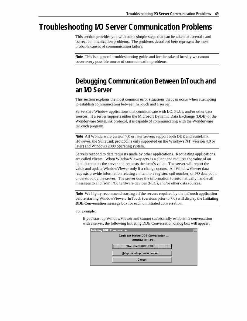
Note We highly recommend starting all the servers required by the InTouch applicationbefore starting WindowViewer. InTouch (versions prior to 7.0) will display the InitiatingDDE Conversation message box for each uninitiated conversation.
For example:
If you start up WindowViewer and cannot successfully establish a conversationwith a server, the following Initiating DDE Conversation dialog box will appear:
50 Wonderware Allen-Bradley ControlLogix I/O Server
The information in the second line indicates that you have at least one I/O typetagname defined in your Tagname Dictionary that is associated with an AccessName that defines OMRONFO as the Application Name, and HLPLC as the TopicName. Make note of exactly how the application and topic names are spelled.
8 This example only applies when using a version of InTouch prior to InTouch7.0.
To troubleshoot communication problems between WindowViewer and the server,perform the following steps as listed below.
Ø Verify the I/O Server is running.
1. Start the server program.
2. Verify the server is running by checking to see if it is in the Windows Task List.
On Windows NT and Windows 2000, click the right mouse button on the Windowstaskbar and select Task Manager from the menu. Click the Applications tab to viewall currently running applications. Or press the CTRL+SHIFT+ESC keys.
Ø If the I/O Server is running, verify the I/O Server's program name is correct in allWindowMaker Access Name definitions.
1. Switch to (or start) WindowMaker. Select Access Names from the Special Menu,the Access Name Definitions dialog box appears listing all Access Names defined inthe WindowMaker.
2. In the Access Names list, select the Access Name referencing the server and clickModify. The Modify Access Name dialog box will appear.
3. Verify the server's program name in the Application Name box is correct. If it iswrong then correct it and click OK , else click Cancel.
8 The server's exact "executable name" must be typed in the Application Namebox in all Access Name definitions. The ".exe" extension is not used.
8 If you are debugging a remote tagname reference, also verify that the nodename for the remote computer in the Node Name box is correct.
4. Repeat steps 2 & 3 and verify the server program name is correct in all AccessNames that use it.
Ø If you still cannot establish a conversation, verify the exact topic name used in theWindowMaker Access Name definitions are defined in the I/O Server program.
1. Close WindowViewer if it is running. The server cannot be configured ifWindowViewer is running.
2. Start the server program.
3. From the server’s Configure menu select Topic Definition. The Topic Definitiondialog box appears listing all topic names defined in the server.
4. Verify that the topic name exists and is spelled exactly the same (including spaces)as the topic name referenced in the WindowMaker Access Name definition.

Troubleshooting I/O Server Communication Problems 51
8 Blank spaces cannot follow the topic name in either the server's TopicDefinition or the Access Name definition.
5. If the topic name is different, either correct it in the server or switch toWindowMaker and correct it in the Access Name definition.
6. Once you performed the above procedure, restart WindowViewer and switch to theserver program. Data should now appear in the server’s program window toindicate that WindowViewer and the server are communicating.
8 The data in the server’s program window indicates the read and write messagesthe server is sending to and receiving from the PLC. These are not errormessages; only status messages are written to the server’s program window.
7. If no data appears in the server’s program window, switch to the WonderwareLogger to check for error messages. For example, a common error message is:
"Error for DDE: OMRONFO|HLPLC!<null>("item") Advise failed"
This message appears when the item defined in one or more tagnames is invalid forthe server.
8 InTouch tagnames use specific naming conventions when accessing data froma server. The valid item names for all Wonderware servers are documented intheir respective user's guides. Typically, the item naming conventions used byeach server are consistent with the names used by the equipment manufacturer.
$ For more information on the Wonderware Logger, see your online FactorySuiteSystem Administrator's Guide.
Ø If you are still experiencing problems, continue with the following troubleshootingsection.
Debugging Communication Between SuiteLinkand an I/O Server If you have successfully applied the debug techniques listed in the previous section andare still experiencing communication problems to a server that is attempting tocommunicate using the SuiteLink protocol, perform the following steps as listed below:
Ø Verify the I/O Server supports the Wonderware SuiteLink protocol, that is, the I/OServer is version 7.0 or above.
Ø Try communicating to the I/O Server using the DDE protocol. If this is not possible,then proceed to the next troubleshooting section otherwise continue with the followingsteps:
1. Verify Microsoft's TCP/IP stack is installed and configured properly.
8 SuiteLink uses the Microsoft TCP/IP stack for its communications even if theclient application and the server reside on the same node.
2. If you do not have an Ethernet card to bind to the TCP/IP stack, install theMicrosoft Loop Back Adapter.
3. Install the Microsoft TCP/IP stack.
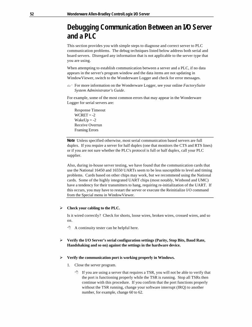
52 Wonderware Allen-Bradley ControlLogix I/O Server
Debugging Communication Between an I/O Serverand a PLCThis section provides you with simple steps to diagnose and correct server to PLCcommunication problems. The debug techniques listed below address both serial andboard servers. Disregard any information that is not applicable to the server type thatyou are using.
When attempting to establish communication between a server and a PLC, if no dataappears in the server's program window and the data items are not updating inWindowViewer, switch to the Wonderware Logger and check for error messages.
$ For more information on the Wonderware Logger, see your online FactorySuiteSystem Administrator's Guide.
For example, some of the most common errors that may appear in the WonderwareLogger for serial servers are:
Response TimeoutWCRET = -2WakeUp = -2Receive OverrunFraming Errors
Note Unless specified otherwise, most serial communication based servers are fullduplex. If you require a server for half duplex (one that monitors the CTS and RTS lines)or if you are not sure whether the PLC's protocol is full or half duplex, call your PLCsupplier.
Also, during in-house server testing, we have found that the communication cards thatuse the National 16450 and 16550 UARTs seem to be less susceptible to level and timingproblems. Cards based on other chips may work, but we recommend using the Nationalcards. Some of the highly integrated UART chips (most notably, Winbond and UMC)have a tendency for their transmitters to hang, requiring re-initialization of the UART. Ifthis occurs, you may have to restart the server or execute the Reinitialize I/O commandfrom the Special menu in WindowViewer.
Ø Check your cabling to the PLC.
Is it wired correctly? Check for shorts, loose wires, broken wires, crossed wires, and soon.
8 A continuity tester can be helpful here.
Ø Verify the I/O Server’s serial configuration settings (Parity, Stop Bits, Baud Rate,Handshaking and so on) against the settings in the hardware device.
Ø Verify the communication port is working properly in Windows.
1. Close the server program.
8 If you are using a server that requires a TSR, you will not be able to verify thatthe port is functioning properly while the TSR is running. Stop all TSRs thencontinue with this procedure. If you confirm that the port functions properlywithout the TSR running, change your software interrupt (IRQ) to anothernumber, for example, change 60 to 62.
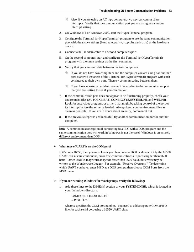
Troubleshooting I/O Server Communication Problems 53
8 Also, if you are using an AT type computer, two devices cannot shareinterrupts. Verify that the communication port you are using has a uniqueinterrupt setting.
2. On Windows NT or Windows 2000, start the HyperTerminal program.
3. Configure the Terminal (or HyperTerminal) program to use the same communicationport with the same settings (baud rate, parity, stop bits and so on) as the hardwaredevice.
4. Connect a null modem cable to a second computer's port.
5. On the second computer, start and configure the Terminal (or HyperTerminal)program with the same settings as the first computer.
6. Verify that you can send data between the two computers.
8 If you do not have two computers and the computer you are using has anotherport, start two instances of the Terminal (or HyperTerminal) program with eachconfigured to their own port. Then try communicating between them.
8 If you have an external modem, connect the modem to the communication portthat you are testing to see if you can dial out.
7. If the communication port does not appear to be functioning properly, check yourenvironment files (AUTOEXE.BAT, CONFIG.SYS, SYSTEM.INI, and WIN.INI).Look for suspicious programs or drivers that might be taking control of the port orits interrupt before the server is loaded. Always keep your environment files asclean as possible. If you are in doubt about an entry, comment it out.
8. If the previous step was unsuccessful, try another communication port or anothercomputer.
Note A common misconception of connecting to a PLC with a DOS program and thesame communication port will work in Windows is not the case! Windows is an entirelydifferent environment than DOS.
Ø What type of UART is on the COM port?
If it’s not a 16550, then you must lower your baud rate to 9600 or slower. Only the 16550UART can sustain continuous, error free communications at speeds higher than 9600baud. Other UARTs may work at speeds faster than 9600 baud, but errors may bewritten to the Wonderware Logger. For example, "Receive Overruns." To determinewhich UART you have, enter MSD at a DOS prompt, then choose COM Ports from theMSD menu.
Ø If you are running Windows for Workgroups, verify the following:
1. Add these lines to the [386Enh] section of your SYSTEM.INI file which is located inyour \Windows directory:
EMMEXCLUDE=A000-EFFFCOMxFIFO=0
where x specifies the COM port number. You need to add a separate COMxFIFOline for each serial port using a 16550 UART chip.

54 Wonderware Allen-Bradley ControlLogix I/O Server
2. If you are running Windows for Workgroups (version 3.1 or later), downloadSERIAL.386 (this fixes a Microsoft bug) from the Wonderware Bulletin Board system(949-727-0726) or from the Wonderware WEB site at:http://wondertech.wonderware.com.
8 The size of this file is 10620 bytes, has a date of 2/17/94 and is a self-extractingzip file called wg1001.exe. It’s located in the "PatchFix Library" on theWonderware BBS in the File Transfers / Patchfix area.
8 You must be registered to access the Wonderware Web site.
3. If the above numbers, 1. and 2., do not work, verify the value of the ComBoostTimeparameter in your SYSTEM.INI file. This parameter represents the number ofmilliseconds a virtual machine processes a COM interrupt. (The default value is 2.)It is not recommended that you change this setting. However, if you are receivingerrors such as "Receive Overruns" or "WCRE=-2", try increasing the value to 20.
Ø Verify the parameters for WWCOMTSR.
Do not specify a receive and/or transmit buffer size of 8!
For example:
Correct:COM1:0 COM2:1,2048,2048COM1:0 COM2:1
Incorrect:COM1:0 COM2:1,8,8
Ø Does your computer crash when trying to communicate through the COM port?
If so, verify that each TSR has a unique software interrupt.
8 A utility, ShowSoft, is available on the Knowledge Base CD that can assist indetermining the available software interrupts.
Ø Does your computer lock up?
Verify the COM port's IRQ’s do not conflict with each other or with other communicationboards in the computer.
Ø If the PLC or field device has more than one COM port, verify the connection to thecorrect port.
The COM port on your computer uses the RS-232 hardware communication standardand connects the cable from the COM port to an RS-232 compliant device.
Note To connect to an RS-422 or RS-485 port on the PLC, you need an RS-232 to RS-422/485 conversion device.
If possible, use an external converter instead of a board-based converter that plugs intoa slot in the computer. A board-based converter is difficult to get working forinexperienced users. If a board-based converter is not set up properly, it can conflictwith other communication boards in the computer such as, internal modems.
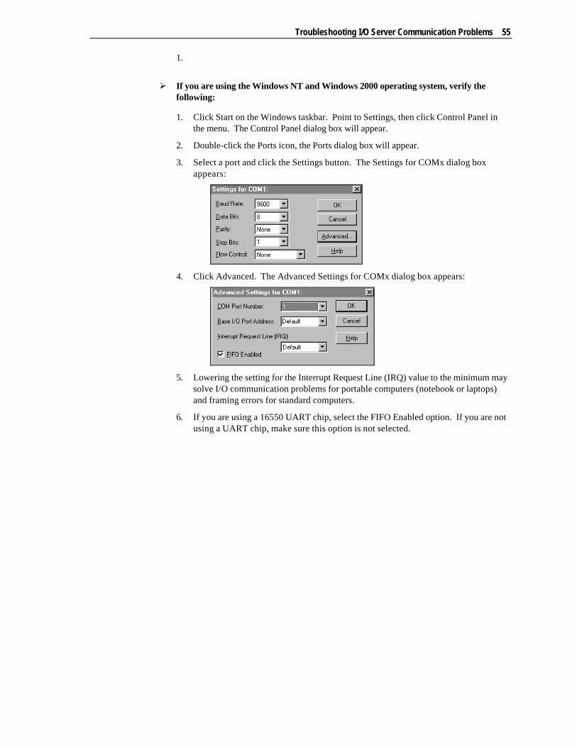
Troubleshooting I/O Server Communication Problems 55
1.
Ø If you are using the Windows NT and Windows 2000 operating system, verify thefollowing:
1. Click Start on the Windows taskbar. Point to Settings, then click Control Panel inthe menu. The Control Panel dialog box will appear.
2. Double-click the Ports icon, the Ports dialog box will appear.
3. Select a port and click the Settings button. The Settings for COMx dialog boxappears:
4. Click Advanced. The Advanced Settings for COMx dialog box appears:
5. Lowering the setting for the Interrupt Request Line (IRQ) value to the minimum maysolve I/O communication problems for portable computers (notebook or laptops)and framing errors for standard computers.
6. If you are using a 16550 UART chip, select the FIFO Enabled option. If you are notusing a UART chip, make sure this option is not selected.
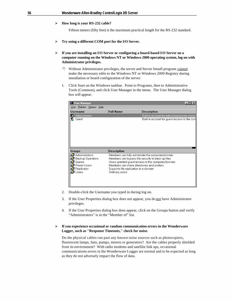
56 Wonderware Allen-Bradley ControlLogix I/O Server
Ø How long is your RS-232 cable?
Fifteen meters (fifty feet) is the maximum practical length for the RS-232 standard.
Ø Try using a different COM port for the I/O Server.
Ø If you are installing an I/O Server or configuring a board-based I/O Server on acomputer running on the Windows NT or Windows 2000 operating system, log on withAdministrator privileges.
8 Without Administrator privileges, the server and Server Install program cannotmake the necessary edits to the Windows NT or Windows 2000 Registry duringinstallation or board configuration of the server.
1. Click Start on the Windows taskbar. Point to Programs, then to AdministrativeTools (Common), and click User Manager in the menu. The User Manager dialogbox will appear:
2. Double-click the Username you typed in during log on.
3. If the User Properties dialog box does not appear, you do not have Administratorprivileges.
4. If the User Properties dialog box does appear, click on the Groups button and verify“Administrators” is in the “Member of” list.
Ø If you experience occasional or random communication errors in the WonderwareLogger, such as "Response Timeouts," check for noise.
Do the physical cables run past any known noise sources such as photocopiers,fluorescent lamps, fans, pumps, motors or generators? Are the cables properly shieldedfrom its environment? With radio modems and satellite link ups, occasionalcommunications errors in the Wonderware Logger are normal and to be expected as longas they do not adversely impact the flow of data.
Troubleshooting I/O Server Communication Problems 57
Ø Increase the Reply Timeout setting in the I/O Server to a value between 5 and 10seconds.
Not allowing the PLC or field device enough time to respond to the server’s request fordata may result in communication errors.
Ø Verify the PLC is properly configured and the cable is good by using the programmingsoftware for the PLC.
1. Connect to the PLC with the programming software. The connection must bethrough the same port and cable. Go into the programming software configurationand write down what the communications parameters are (baud rates, routes, nodenumber, error checking, etc.).
2. Close the programming software. Open the I/O Server and verify thecommunications settings are the same.
3. Poke data into the PLC with InTouch or WWClient.
4. Shut down the server and use the programming software to verify that the valueswere correctly poked.
8 Performance of this test depends upon the type of PLC you are using.
Ø Reinstall the I/O Server and verify that you are using the latest version.
Wonderware is continually improving our servers and using the latest version willguarantee the best results.
8 New versions of the Wonderware I/O Servers are released regularly on the I/OServer CD included in Comprehensive Support Shipments and they are alsoavailable from the Wonderware WEB site at: http://www.wonderware.com.
Ø Move the I/O Server’s configuration file to another location on the computer’s harddrive. This will clear all configuration for the I/O Server, then reconfigure the I/OServer.
8 Wonderware server configuration files are typically the exact same name as theserver’s executable name with the .cfg extension. For example, OMRONFO.cfg.Refer to the Configuration File section of the specific server user’s guide for theexact name of the configuration file.
Ø If possible, reinstall the Windows operating system.
Files installed earlier on your computer or the NT registry may have been corrupted oraccidentally modified.
Ø If these troubleshooting suggestions do not solve your problem, there may be a problemwith your computer. There are many subtle differences between the various computerhardware brands. Using a computer that is a different brand and meets the followingcriteria:
1. Select a different PC manufacturer and if this is not possible, try a different PC modelfrom the same manufacturer.
2. The computer can not use an OEM (Original Equipment Manufacturer) version ofMicrosoft Windows. We highly recommend using only a Microsoft Windowsproduct. Contact your vendor to determine if installing an off-the-shelf copy ofMicrosoft Windows will cause any problems.

58 Wonderware Allen-Bradley ControlLogix I/O Server
Ø If you feel you have tested all possible situations that may be causing your failed I/Ocommunications, contact your local Wonderware distributor for technical support.
$ For more information on obtaining technical support, see your online FactorySuiteSystem Administrator’s Guide.