al2xxx - beckhoffftp.beckhoff.com/download/document/motion/al2xxx...foreword al2xxx - installation...
TRANSCRIPT
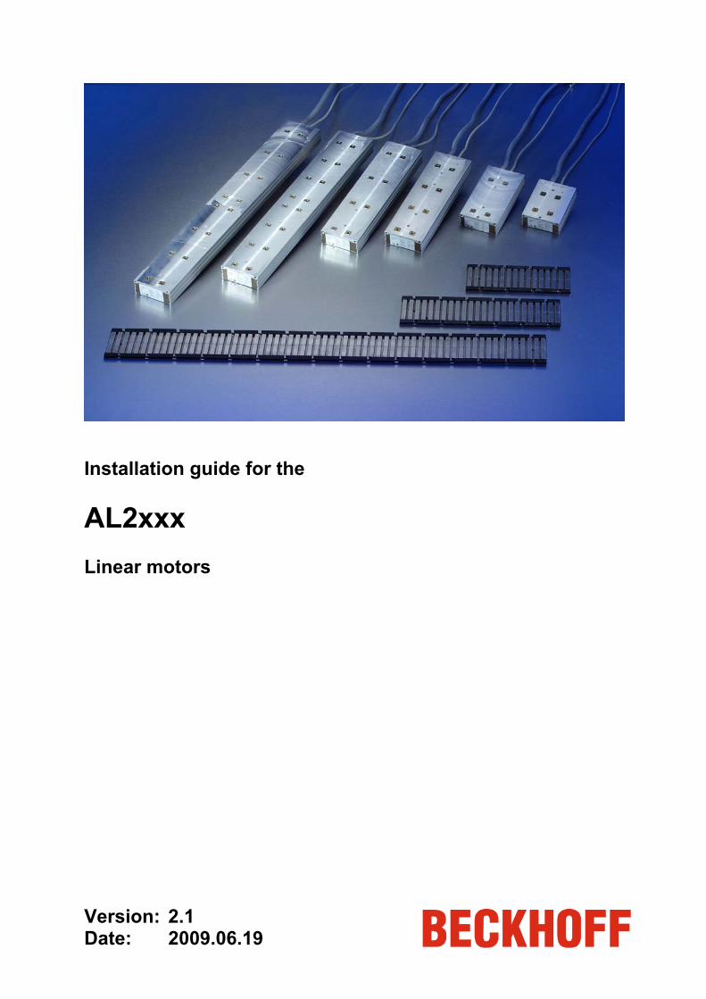
Installation guide for the AL2xxx Linear motors Version: 2.1 Date: 2009.06.19

Table of contents
AL2xxx – Installation guide
Table of contents 1 Foreword 1
1.1 Notes on the documentation 1 1.1.1 Liability conditions 1 1.1.2 Delivery conditions 1 1.1.3 Copyright 1
1.2 General safety instructions 2 1.2.1 State at delivery 2 1.2.2 Description of safety symbols 2
1.3 Linear motor systems - notes 3 1.3.1 Hazards in linear motor systems 4
1.4 EU declaration 5 1.5 Documentation issue status 5
2 Components 6 2.1 Basic components 7
2.1.1 Coil unit 7 2.1.2 Magnetic plate 7
2.2 Special components 8 2.2.1 Protective plate 8
2.3 Additional equipment 10 2.3.1 Screws and locating pins 10 2.3.2 Control and measurement unit 10 2.3.3 Tools 10

Table of contents
AL2xxx – Installation guide
3 Installation 11 3.1 Installation sequence 11 3.2 Assembly notes 13
3.2.1 Assembling the coil unit 13 3.2.2 Assembling the magnetic plates 15 3.2.3 18
3.3 Electrical connections 20 3.3.1 General comments 20 3.3.2 Motor lines 21 3.3.3 Protective earth (PE) 21 3.3.4 Temperature sensor 21 3.3.5 PTC specification 22 3.3.6 KTY Specification 23 3.3.7 Polarity test 24
3.4 Dismantling sequence 24
4 Additional installation notes 25 4.1 General 25 4.2 Connections for the water cooling system (AL20xx only) 25
4.2.1 Requirements 25 4.2.2 Inserting the water cooling connections 26 4.2.3 Connecting the hoses 26
5 Operation 27 5.1 General 27 5.2 Setting 27 5.3 Verification 28
5.3.1 Limit switch 28 5.4 Starting 28 5.5 Optimizing the control settings 28
6 Appendix 29 6.1 Support and Service 29
6.1.1 Beckhoff's branch offices and representatives 29 6.2 Beckhoff Headquarters 29
Assembling the end bridges

Foreword
AL2xxx - Installation guide 1
1 Foreword
1.1 Notes on the documentation This description is only intended for the use of trained specialists in control and automation engineering who are familiar with the applicable national standards. It is essential that the following notes and explanations are followed when installing and commissioning these components.
1.1.1 Liability conditions
The responsible staff must ensure that the application or use of the products described satisfy all the requirements for safety, including all the relevant laws, regulations, guidelines and standards.
The documentation has been prepared with care. The products described are, however, constantly under development. For this reason, the documentation may not always be have been fully checked for consistency with the performance data, standards or other characteristics described. None of the statements in this manual represent a guarantee for as set out in § 443 of the German Civil Code or a statement about the assumed use according to the contract as set out in § 434 para. 1 clause 1 no. 1 of the German Civil Code. In the event that it contains technical or editorial errors, we retain the right to make alterations at any time and without warning. No claims for the modification of products that have already been supplied may be made on the basis of the data, diagrams and descriptions in this documentation.
1.1.2 Delivery conditions
In addition, the general delivery conditions of the company Beckhoff Automation GmbH apply.
1.1.3 Copyright © This documentation is protected by copyright. Any reproduction or third party use of this publication, whether in whole or in part, without the written permission of Beckhoff Automation GmbH, is forbidden.
Foreword
2 AL2xxx - Installation guide
1.2 General safety instructions
1.2.1 State at delivery
All the components are supplied in particular hardware and software configurations appropriate for the application. Modifications to hardware or software configurations other than those described in the documentation are not permitted, and nullify the liability of Beckhoff Automation GmbH.
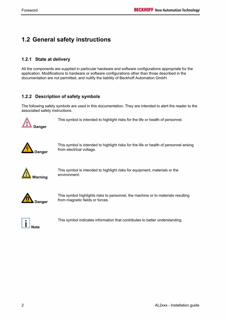
1.2.2 Description of safety symbols
The following safety symbols are used in this documentation. They are intended to alert the reader to the associated safety instructions.
Danger
This symbol is intended to highlight risks for the life or health of personnel.
Danger
This symbol is intended to highlight risks for the life or health of personnel arising from electrical voltage.
Warning
This symbol is intended to highlight risks for equipment, materials or the environment.
Danger This symbol highlights risks to personnel, the machine or to materials resulting from magnetic fields or forces.
i Note
This symbol indicates information that contributes to better understanding.
Foreword
AL2xxx - Installation guide 3
1.3 Linear motor systems - notes Generally speaking, a linear motor system is part of a particular machine. Linear motors from Beckhoff can be combined with a large number of other devices. This installation manual is intended for technicians and engineers who intend to construct a machine incorporating a linear motor system of this type.
A number of important safety aspects should be considered before installing a linear motor system. You will find relevant comments in the chapter on Hazards in linear motor systems. Please read it carefully.
In addition to mounting the coil unit and the magnetic plates, installation includes electrical wiring between the motor, servo controller and the linear position transducer.
A number of necessary settings are then explained. Your linear motor can then make its first transit.
Please contact Beckhoff for further information and support. You will find the addresses of the responsible Beckhoff branch or representative in the appendix to this documentation, or on our website (www.beckhoff.com).
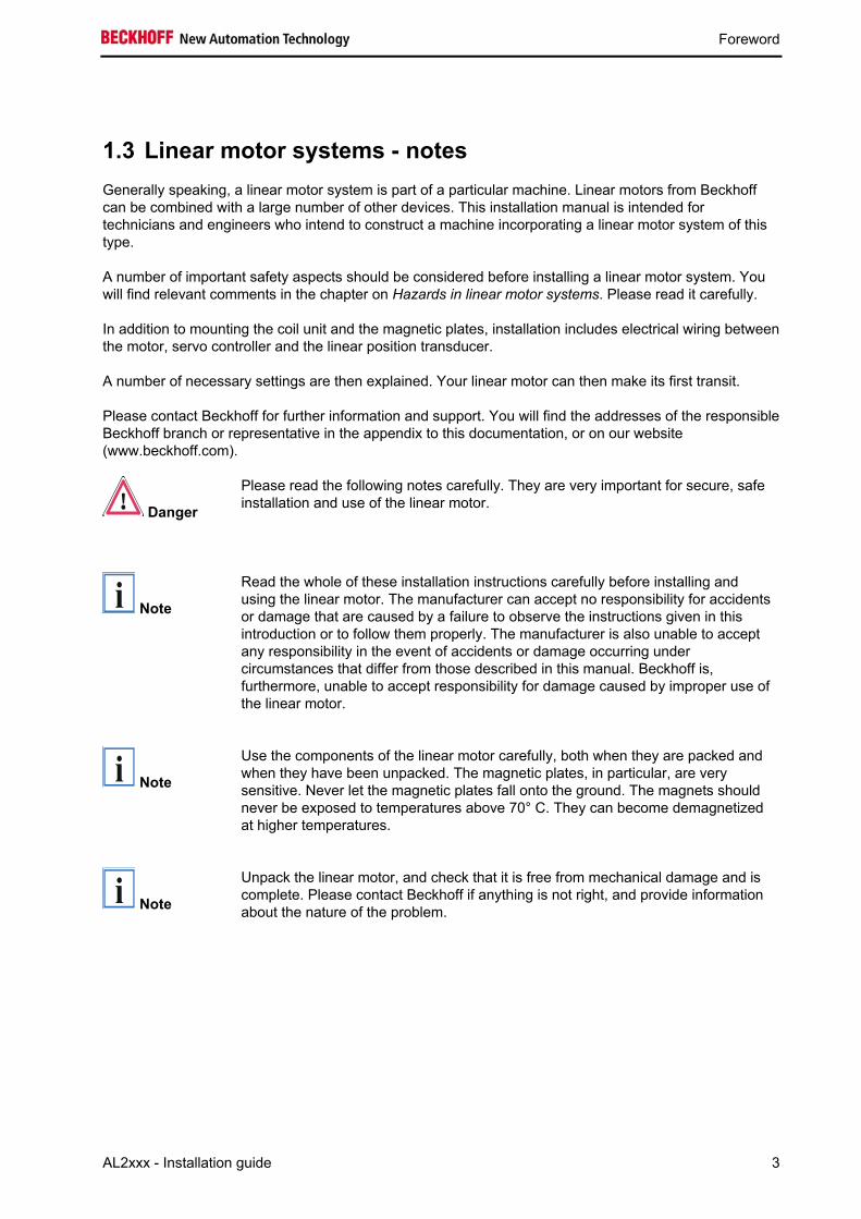
Danger
Please read the following notes carefully. They are very important for secure, safe installation and use of the linear motor.
i Note
Read the whole of these installation instructions carefully before installing and using the linear motor. The manufacturer can accept no responsibility for accidents or damage that are caused by a failure to observe the instructions given in this introduction or to follow them properly. The manufacturer is also unable to accept any responsibility in the event of accidents or damage occurring under circumstances that differ from those described in this manual. Beckhoff is, furthermore, unable to accept responsibility for damage caused by improper use of the linear motor.
i Note
Use the components of the linear motor carefully, both when they are packed and when they have been unpacked. The magnetic plates, in particular, are very sensitive. Never let the magnetic plates fall onto the ground. The magnets should never be exposed to temperatures above 70° C. They can become demagnetized at higher temperatures.
i Note
Unpack the linear motor, and check that it is free from mechanical damage and is complete. Please contact Beckhoff if anything is not right, and provide information about the nature of the problem.

Foreword
4 AL2xxx - Installation guide
1.3.1 Hazards in linear motor systems
i Note
A linear motor is used as part of a larger machine. The user is responsible for ensuring that the machine satisfies all EU requirements.
Danger
The magnetic plates exercise a powerful attractive force on any soft-magnetic materials such as iron. These forces are more than the hand can manage. They can cause serious injuries.
Do not bring any soft-magnetic objects closer than 10 cm to the magnetic side of the magnetic plates.
Make sure that the magnetic plates are securely fastened in your machine before removing the protective plates that neutralize the magnetic field.
It is necessary that you replace the protective plates to neutralize the magnetic field before dismantling the magnetic plates.
Danger
If, at any stage, and regardless of the circumstances, you have any doubts about the safety of the linear motor, do not switch it on but make contact with Beckhoff.
Danger
The linear motor is driven by a servo drive. It is possible for a power failure, or for some other serious fault, to cause the motor to start up automatically. Provide mechanical safety equipment that will protect the motor and your machine from being damaged in such circumstances.
Danger
Before installing the motor, make sure that the main power supply is earthed in accordance with the applicable regulations.
Danger
Ensure that an effective electrical earth is available. Make sure that the cable connection terminals are not electrically live before you connect the machine.
Danger
An earth connection made to a non-conductive surface, such as granite, is ineffective. In such cases, the protective earth must be established with the aid of an earthing cable of adequate cross-section.
Danger
It is essential that you disconnect electrical power from the system before carrying out any inspection or servicing work. Make sure that it is not possible for it to be accidentally connected again.
Danger
In cases where water cooling is used, be aware of the risk of electric shock that arises if the coolant comes into contact with the power supply.

Foreword
AL2xxx - Installation guide 5
1.4 EU declaration Beckhoff declares that all Beckhoff linear motors are manufactured in accordance with the applicable European specifications, and that they meet the following standards:
Standard # Issue date General title of the standard EN 60034 05-1998 Rotating electrical machines EN 60204 (-1) 02-1995 Safety of machinery EN 50081-2 08-1993 Electromagnetic compatibility, generic emission standard: industrial
environment EN 50082-2 03-1995 Electromagnetic compatibility, generic immunity standard: industrial
environment
1.5 Documentation issue status Version Comment 2.0 New release 1.9 Corrections to spelling and references to figures 1.8 Internal version for corrections 1.0 Old version from 2001-11-08
Components
6 AL2xxx - Installation guide
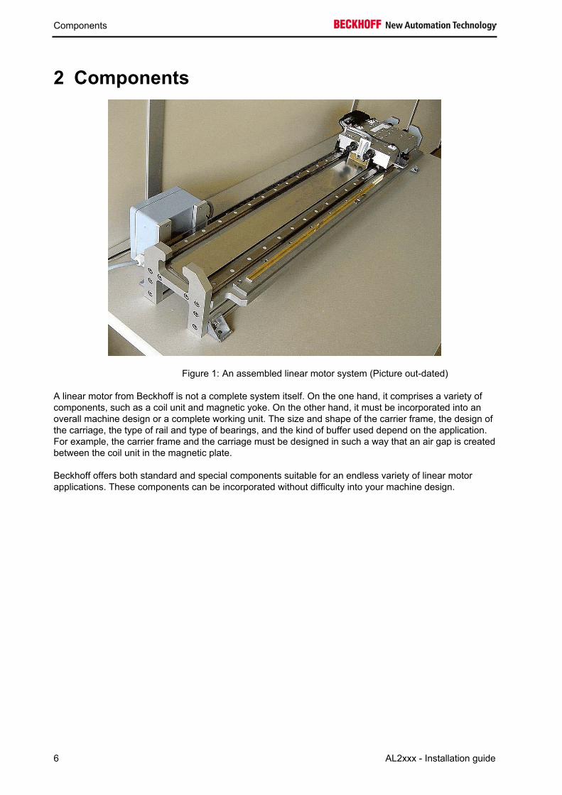
2 Components
A linear motor from Beckhoff is not a complete system itself. On the one hand, it comprises a variety of components, such as a coil unit and magnetic yoke. On the other hand, it must be incorporated into an overall machine design or a complete working unit. The size and shape of the carrier frame, the design of the carriage, the type of rail and type of bearings, and the kind of buffer used depend on the application. For example, the carrier frame and the carriage must be designed in such a way that an air gap is created between the coil unit in the magnetic plate.
Beckhoff offers both standard and special components suitable for an endless variety of linear motor applications. These components can be incorporated without difficulty into your machine design.
Figure 1: An assembled linear motor system (Picture out-dated)
Components
AL2xxx - Installation guide 7
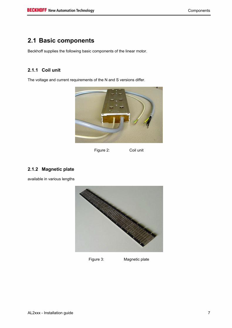
2.1 Basic components Beckhoff supplies the following basic components of the linear motor.
2.1.1 Coil unit
The voltage and current requirements of the N and S versions differ.
Figure 2: Coil unit
2.1.2 Magnetic plate
available in various lengths
Figure 3: Magnetic plate
Components
8 AL2xxx - Installation guide
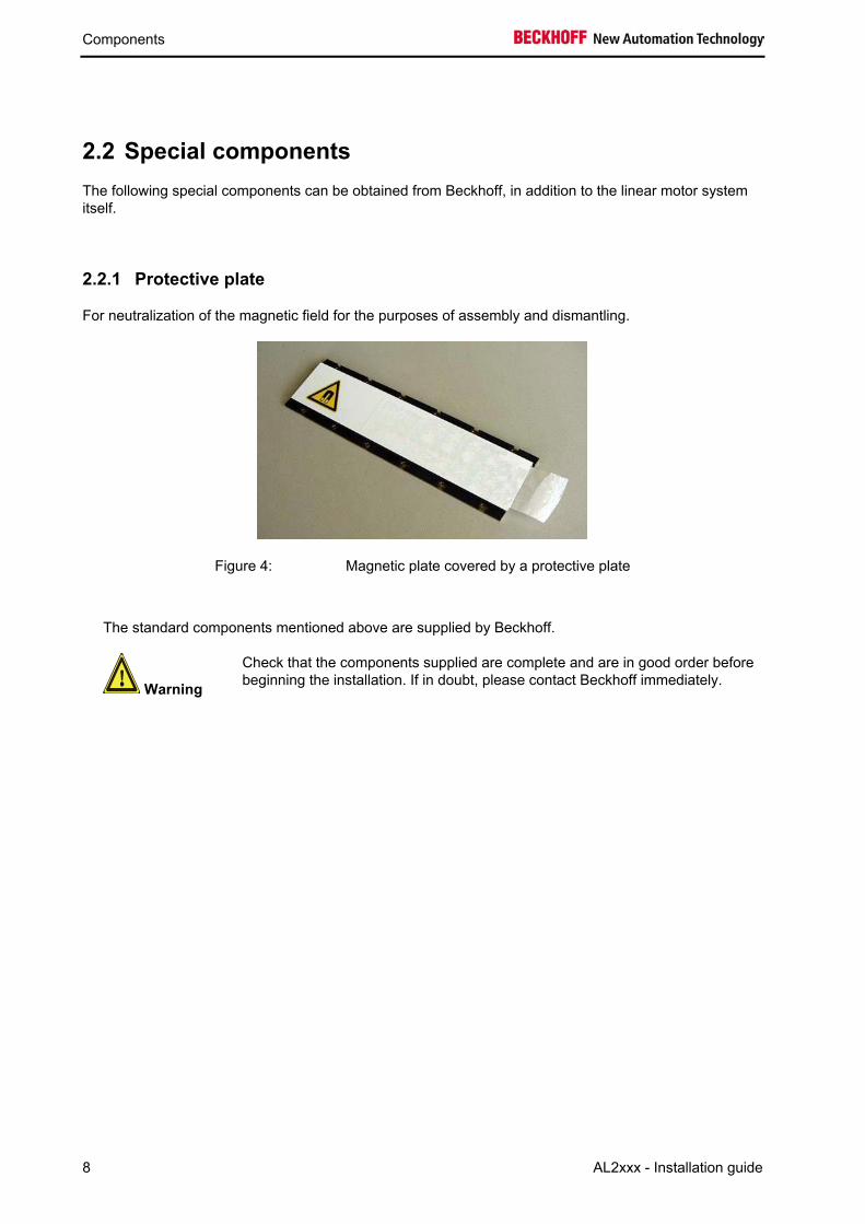
2.2 Special components The following special components can be obtained from Beckhoff, in addition to the linear motor system itself.
2.2.1 Protective plate
For neutralization of the magnetic field for the purposes of assembly and dismantling.
Figure 4: Magnetic plate covered by a protective plate
The standard components mentioned above are supplied by Beckhoff.
Warning
Check that the components supplied are complete and are in good order before beginning the installation. If in doubt, please contact Beckhoff immediately.

Components
AL2xxx - Installation guide 9
Notes:

Components
10 AL2xxx - Installation guide
2.3 Additional equipment To install your linear motor properly, you also need:
• fastening components, such as screws and pegs; • the appropriate tools.
These are not included as part of the standard equipment.
2.3.1 Screws and locating pins
Figure 7: Screws and locating pins
The following screws and pins are needed to position and fasten the coil unit to the carriage, and also the magnetic plates to the carrier frame.
Attribute TM TL TB Screws for magnetic plates (stainless) M5x10, DIN7984 M5x10, DIN7984 M5x16, DIN912 Screws for coil unit (steel); length depends on the thickness of the carriage
M4, DIN912 M5, DIN912 M5, DIN912
Locating pins (stainless) 5h8 M3
2.3.2 Control and measurement unit
The following are required: • one AX2000, AX2500 or AX5000 Servo Drive; • a graduated rule and a linear position transducer, or the MES scaleless feedback system • power supply, cable and plug.
Further information is available by request from Beckhoff.
2.3.3 Tools
For the installation you require: • a set of Allen keys • a pair of safety gloves (for handling the steel cover).

Installation
AL2xxx - Installation guide 11
3 Installation
Figure 8: Installation
3.1 Installation sequence
Danger The sequence specified in this introduction for the installation must be followed. A different sequence can give rise to dangerous situations, and can lead to damage resulting from uncontrolled magnetic attraction.
Installation of the carrier frame must be complete before installing the linear motor components. Both the rail and the graduated rule must be properly mounted and aligned on the carrier frame. The carriage must be fitted with bearings, buffers, a linear probe and the necessary cables in such a way that smooth, safe and well-positioned transit of the carriage along its track is ensured. Proper functioning of the bearings and buffers, and guidance of the movable cables, must all be tested.
i Note
If a water cooling unit is being used, please read Chapter 4.
Installation
12 AL2xxx - Installation guide
The correct installation sequence is as follows:
1. Attach the connections for the water cooling (if one is being used) to the coil unit.
2. Mount the coil unit on the carriage.
3. Move the carriage to the end of the track. Secure the carriage in such a way as to prevent unwanted movement.
4. Attach the magnetic plates to the exposed part of the track. Arrange for the magnetic plates to be covered with protective plates. Keep the magnetic plates at least 10 cm away from the coil unit.
5. Remove the protective plates after the magnetic plates have been assembled.
6. Move the carriage over the magnetic plates that have just been assembled. Secure the carriage in such a way as to prevent unwanted movement.
7. Assemble the remaining magnetic plates.
Attach the cables.
These steps are explained in more detail in the following sections.
8.
Installation
AL2xxx - Installation guide 13
3.2 Assembly notes
3.2.1 Assembling the coil unit
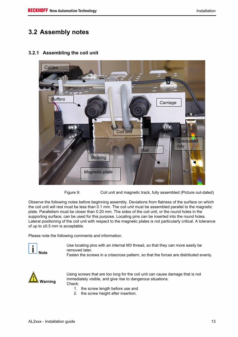
Figure 9:
Observe the following notes before beginning assembly. Deviations from flatness of the surface on which the coil unit will rest must be less than 0.1 mm. The coil unit must be assembled parallel to the magnetic plate. Parallelism must be closer than 0.20 mm. The sides of the coil unit, or the round holes in the supporting surface, can be used for this purpose. Locating pins can be inserted into the round holes. Lateral positioning of the coil unit with respect to the magnetic plates is not particularly critical. A tolerance of up to ±0.5 mm is acceptable.
Please note the following comments and information.
i Note
Use locating pins with an internal M3 thread, so that they can more easily be removed later. Fasten the screws in a crisscross pattern, so that the forces are distributed evenly.
Warning
Using screws that are too long for the coil unit can cause damage that is not immediately visible, and give rise to dangerous situations. Check:
1. the screw length before use and 2. the screw height after insertion.
Cables
Carriage Buffers
Bearing
Magnetic plate
Coil unit
Graduated rule
Rail
Coil unit and magnetic track, fully assembled (Picture out-dated)

Installation
14 AL2xxx - Installation guide
Screws for the coil unit TM TL TB Screw (steel) M4 M5 M5 Depth of the screw insertion into the internal thread
Min: 4 mm Max: 5 mm
Min: 4 mm Max: 5 mm
Min: 4,5 mm Max: 6,5 mm
Tightening torque 2.0 – 3.0 Nm 3.0 – 5.0 Nm 3.0 – 5.0 Nm
If water cooling is used, make sure that the connections for the water cooling can be positioned up to 1 mm above the support surface. Ensure that enough clearance is maintained, or else use a spacer plate at least 1 mm thick. See also Chapter 4.
Installation
AL2xxx - Installation guide 15
3.2.2 Assembling the magnetic plates
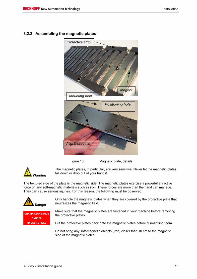
Figure 10: Magnetic plate, details
Warning
The magnetic plates, in particular, are very sensitive. Never let the magnetic plates fall down or drop out of your hands!
The textured side of the plate is the magnetic side. The magnetic plates exercise a powerful attractive force on any soft-magnetic materials such as iron. These forces are more than the hand can manage. They can cause serious injuries. For this reason, the following must be observed:
Danger
Only handle the magnetic plates when they are covered by the protective plate that neutralizes the magnetic field.
Make sure that the magnetic plates are fastened in your machine before removing the protective plates.
Put the protective plates back onto the magnetic plates before dismantling them.
Do not bring any soft-magnetic objects (iron) closer than 10 cm to the magnetic side of the magnetic plates.
Positioning hole
Magnet
Protective strip
Alignment hole
Mounting hole

Installation
16 AL2xxx - Installation guide
Figure 11: Carrier frame, details
Move the carriage to one end of the track. The first magnetic plate is fitted against the other end of the track. Secure the carriage in such a way as to prevent unwanted movement. Make sure that the support surface is free from dust and small particles.
1. Place the locating pins in the positioning holes of the carrier frame (see Figure 11, Carrier frame, details).
2. Select the holes according to the position of the ø5 precision positioning holes in the magnetic plate (see Figure 10, Magnetic plate, details).
i Note
Use pins with an internal M3 thread, so that they can more easily be removed later.
The total length of locating pin above the assembly surface on the magnetic plate must not be greater than 3.5 mm.
Figure 12: Aligning the magnetic plate
1. Make sure that the magnetic plate is correctly aligned. At the end, all the magnetic plates that have been fitted must be aligned in the same direction. Example: All magnetic plates must be installed so that the alignment holes point in the upper right corner (see Aligning the magnetic plate). This is very important, as the linear motor can lose control if assembly is incorrect.
Mounting hole with internal M5 thread
Positioning hole
Alignment hole

Installation
AL2xxx - Installation guide 17
2. Fasten the magnetic plate to the carrier frame. The thread depth should be at least 6.5 mm. The tightening torque for stainless steel is 2.5 to 3.5 Nm. All the holes must be used!
3. Remove the protective plate from the assembled magnetic plate, and push the carriage to the other end of the track. Secure the carriage, to prevent unwanted movement (this can be done by replacing the protective plate, see Figure 13). Make sure once again that the support surface is free from dust and small particles.
Figure 13: Secure the carriage with a protective plate
4. The other magnetic plates can now be assembled in a similar way. Correct alignment of the plates can also be recognized when each subsequent plate is fitted. Adjacent plates must attract one another. If they repel one another, they are wrongly aligned.
Figure 14: Put the next magnetic plate in place
5. Finally, remove all the protective plates, and check that the carriage can move freely and smoothly over the magnetic plates. If an irregularity in the force is noticeable at the edges of the magnetic plates, you should check the plate alignment.
Installation
18 AL2xxx - Installation guide
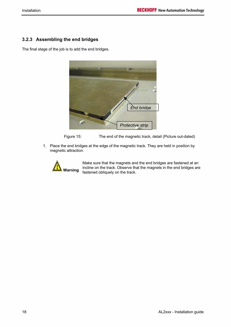
Figure 15:
1. Place the end bridges at the edge of the magnetic track. They are held in position by magnetic attraction.
End bridge
Protective strip
3.2.3 Assembling the end bridges
The final stage of the job is to add the end bridges.
Warning
Make sure that the magnets and the end bridges are fastened at an incline on the track. Observe that the magnets in the end bridges are fastened obliquely on the track.
The end of the magnetic track, detail (Picture out-dated)

Installation
AL2xxx - Installation guide 19
Notes

Installation
20 AL2xxx - Installation guide
3.3 Electrical connections
Danger
Make sure that the electrical power has been disconnected before doing any work on the machine.
Work carefully! Carefully follow the installation instructions for the servo drive as well as those in this installation manual. Ensure that the linear motor system, considered as a whole, satisfies all the applicable electrical directives.
3.3.1 General comments
The electrical cabling for the linear motor is implemented with the aid of two 1-meter external cables: a power cable and a thermal protection contact cable. Both cables have a woven metallic cable screen and plugs for reasons of immunity to electrical interference. The wiring plan is illustrated in Figure 17.
Note that these cables are not suitable for use as trailing cables. Ready-made cables, with special specifications for bending radius, length, replaceability and so forth are available for this purpose.
L1
L1
L2
L2
L3
L3
gr/ye
white
brown
ye
green
PE
Linearmotor
Slide
PTC
KTY
Servoamplifier
Figure 18: Wiring plan for the Ironcore linear motor.
Installation
AL2xxx - Installation guide 21
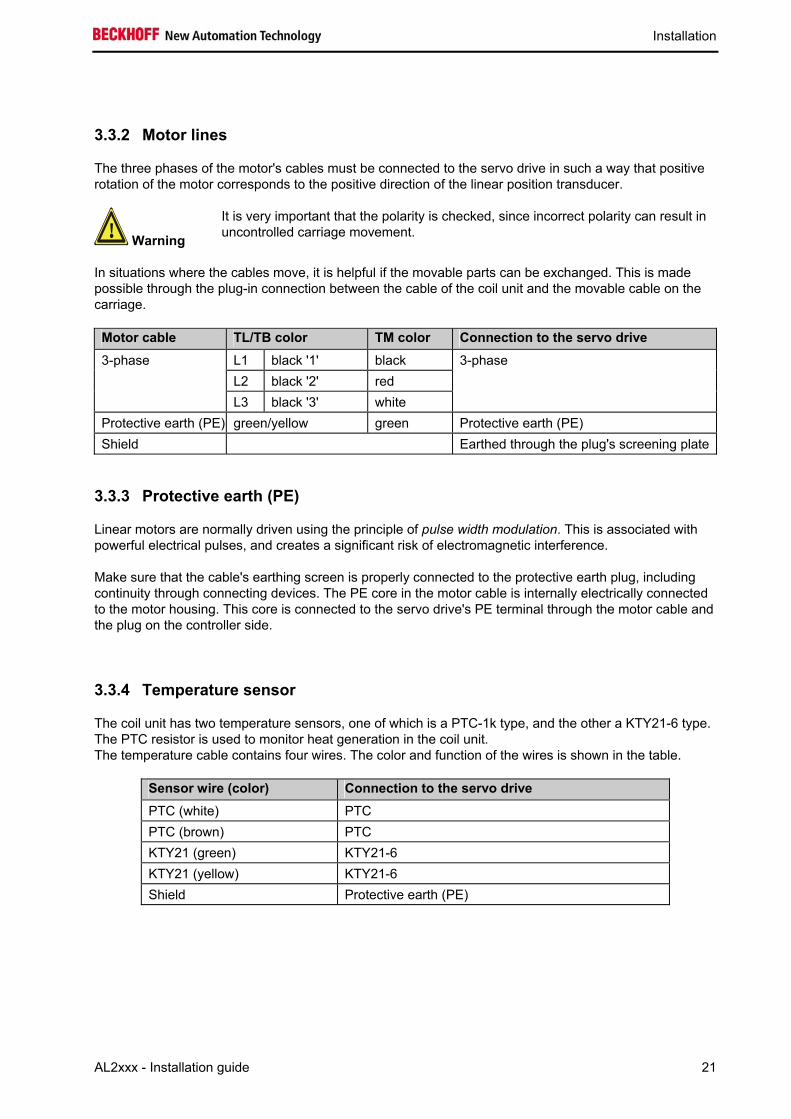
3.3.2 Motor lines
The three phases of the motor's cables must be connected to the servo drive in such a way that positive rotation of the motor corresponds to the positive direction of the linear position transducer.
Warning
It is very important that the polarity is checked, since incorrect polarity can result in uncontrolled carriage movement.
In situations where the cables move, it is helpful if the movable parts can be exchanged. This is made possible through the plug-in connection between the cable of the coil unit and the movable cable on the carriage.
Motor cable TL/TB color TM color Connection to the servo drive L1 black '1' black L2 black '2' red
3-phase
L3 black '3' white
3-phase
Protective earth (PE) green/yellow green Protective earth (PE) Shield Earthed through the plug's screening plate
3.3.3 Protective earth (PE)
Linear motors are normally driven using the principle of pulse width modulation. This is associated with powerful electrical pulses, and creates a significant risk of electromagnetic interference.
Make sure that the cable's earthing screen is properly connected to the protective earth plug, including continuity through connecting devices. The PE core in the motor cable is internally electrically connected to the motor housing. This core is connected to the servo drive's PE terminal through the motor cable and the plug on the controller side.
3.3.4 Temperature sensor
The coil unit has two temperature sensors, one of which is a PTC-1k type, and the other a KTY21-6 type. The PTC resistor is used to monitor heat generation in the coil unit. The temperature cable contains four wires. The color and function of the wires is shown in the table.
Sensor wire (color) Connection to the servo drive PTC (white) PTC PTC (brown) PTC KTY21 (green) KTY21-6 KTY21 (yellow) KTY21-6 Shield Protective earth (PE)
Installation
22 AL2xxx - Installation guide
3.3.5 PTC specification
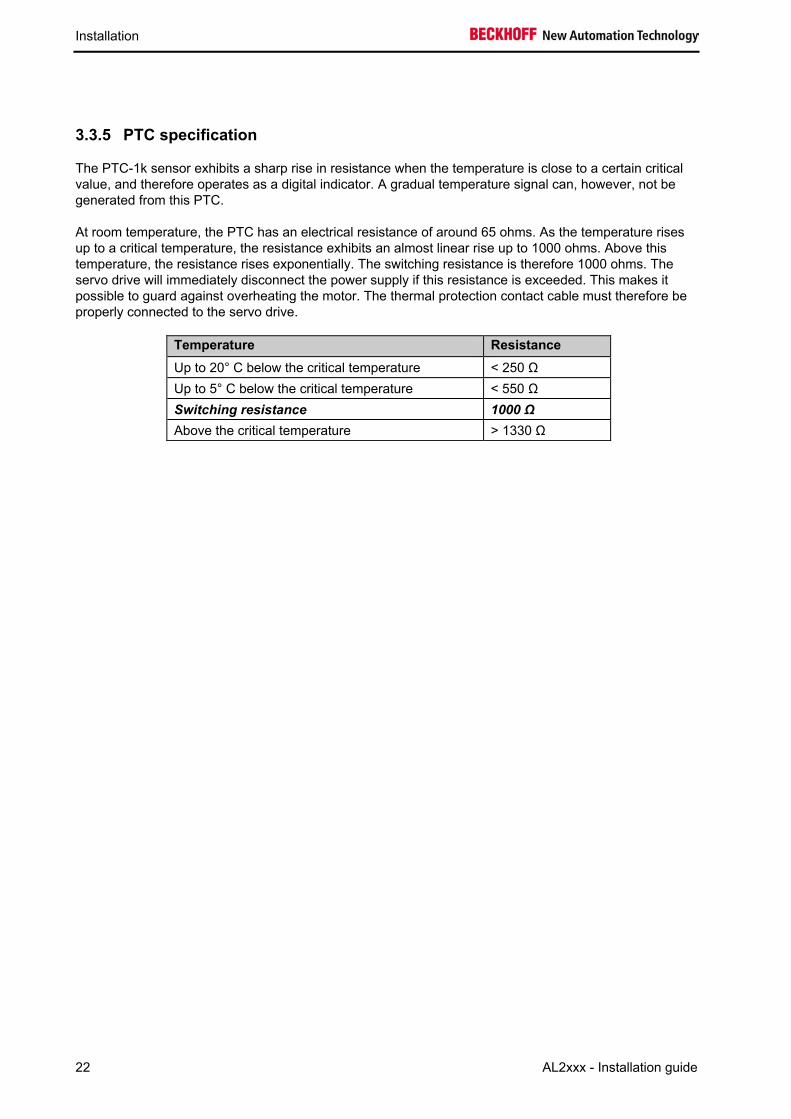
The PTC-1k sensor exhibits a sharp rise in resistance when the temperature is close to a certain critical value, and therefore operates as a digital indicator. A gradual temperature signal can, however, not be generated from this PTC.
At room temperature, the PTC has an electrical resistance of around 65 ohms. As the temperature rises up to a critical temperature, the resistance exhibits an almost linear rise up to 1000 ohms. Above this temperature, the resistance rises exponentially. The switching resistance is therefore 1000 ohms. The servo drive will immediately disconnect the power supply if this resistance is exceeded. This makes it possible to guard against overheating the motor. The thermal protection contact cable must therefore be properly connected to the servo drive.
Temperature Resistance Up to 20° C below the critical temperature < 250 Ω Up to 5° C below the critical temperature < 550 Ω Switching resistance 1000 Ω Above the critical temperature > 1330 Ω

Installation
AL2xxx - Installation guide 23
3.3.6 KTY Specification
The KTY 21-6 sensor has a quite stable and moderate temperature coefficient. The KTY is able to acquire temperature measurements up to high values. The sensor is, for this reason, particularly suitable for monitoring the temperature of the coil unit.
Figure 19: Temperature dependency of the KTY sensor
T (ºC) 0 10 20 30 40 50 60 70 80 90 100 110 120 130RKTY 815 886 961 1040 1123 1209 1300 1394 1492 1594 1700 1810 1923 2041
The sensor requires a continuous current of between 0 and 2 mA. The resistance does not respond linearly to temperature. A linear current/temperature relationship can be obtained by connecting the resistors in a circuit as shown in Figure 19. The basic tolerance is around ±5ºC (with shunt resistors). If necessary, this can be improved to ±1ºC if the circuit is calibrated at one or two relevant temperatures. Please contact Beckhoff if you need more information.
Figure 20: Circuit for a linear KTY voltage signal
Installation
24 AL2xxx - Installation guide
3.3.7 Polarity test
Warning
Before the test, make sure that the linear motor system has suitable electrical and mechanical protection.
There is one way of checking the polarity. From the movement of an external resolver it is possible to establish whether the direction of movement of the motor corresponds to the counting direction of the resolver. If this is the case, the motor is connected correctly. Otherwise, two phases in the motor cable - phases 1 and 3 - must be swapped.
All Beckhoff's linear motors have identical internal wiring connections, so that a single test is enough to determine the polarity of a particular combination of motor and graduated rule. If more than one axis is being constructed in a similar way, the polarity will be identical.
If necessary, please contact Beckhoff.
3.4 Dismantling sequence
Danger The dismantling sequence given in these instructions must be followed. A different sequence can give rise to dangerous situations, and can lead to damage resulting from uncontrolled magnetic attraction.
The correct dismantling sequence is as follows:
1. Disconnect the cables and (if used) the hoses for the water cooling unit.
2. Move the carriage to one side. Secure the carriage in such a way as to prevent unwanted movement.
Cover each magnetic plate that needs to be removed with a neutralizing protective plate.
Remove one or more magnetic plates. The distance between the magnetic plates and the coil unit during this process should not be less than 10 cm.
Move the carriage to the other side. Secure the carriage in such a way as to prevent unwanted movement.
Remove the remaining magnetic plates.
Remove the coil unit from the carriage.
3.
4.
5.
6.
7.

Additional installation notes
AL2xxx - Installation guide 25
4 Additional installation notes
4.1 General This chapter considers the possible installation of a water cooling unit. Water cooling can only be used with the AL20xx series in the standard range of Beckhoff linear motors.
Warning
If you plan to obtain an AL2400 or an AL2800 linear motor system, and water cooling will be necessary, please contact Beckhoff.
Beckhoff can accept no responsibility for any damage resulting from a leaky water cooling system.
4.2 Connections for the water cooling system (AL20xx only)
4.2.1 Requirements
In order to connect the water cooling unit to the coil unit, you need at least:
1. PVC hoses (internal diameter 4 mm)
2. 4 M5 hose connectors
3. M5 plastic seals
4. Loctite 638/648 sealing compound
Please contact Beckhoff for advice regarding the dimensions of the coil unit and the position of the standard connections to the water cooling unit.
Warning
If other connectors are used, this can lead to more pressure loss than stated.

Additional installation notes
26 AL2xxx - Installation guide
4.2.2 Inserting the water cooling connections
M5 connections can be inserted if desired. Make sure that the minimum diameter for water flow is at least 2.5 mm, and that the internal diameter of the hose is at least 4 mm.
1. Degrease the connector and the threaded holes. Allow the degreasing agent to evaporate completely before continuing.
2. Place the plastic sealing ring on the connector. 3. Apply a drop of Loctite 638/648 adhesive to the thread, and spread it all the way round. 4. Attach the connector, and turn it until the sealing ring is visibly deformed. (This only
requires a torque of 0.2 to 0.3 Nm. Do not tighten excessively!) 5. Remove the excess adhesive. 6. Let the adhesive harden for about 4 hours before stressing it. 7. Let the adhesive harden for about 12 hours before exposing it to pressure. 8. The hoses must match the chosen connectors.
Water cooling system connectors for hoses with an internal diameter of 4 mm include, for instance, the Festo PU-4 pneumatic or the very flexible Rauclair E 4x1 PVC hose. Both of these hoses and the connectors can withstand the pressure of 2 bar.
4.2.3 Connecting the hoses
The connectors must be free from oil and grease when the hoses are attached.
The two cooling channels can be connected in series. The minimum flow rate is 1 l/min, requiring a pressure drop of less than 1 bar.
It is also possible to connect the two cooling lines in parallel. This method of connection does reduce the pressure drop, although only when cavitation-free Y-branches with a diameter of 6-8 mm are used.

Operation
AL2xxx - Installation guide 27
5 Operation
5.1 General Once you are sure that the linear motor system is properly assembled, both mechanically and electrically, in your equipment, you can start operation of your motor system.
Nevertheless, check the system one final time before switching it on:
i Note
1. Can the carriage move freely over the whole of the magnetic track, without the carriage touching a magnetic yoke?
2. Are the mechanical end-stops, limit switches and buffers properly dimensioned, and are they configured correctly?
3. Does your system have an emergency off switch? 4. Is the thermal protection contact cable connected? 5. Is the motor cable properly connected? 6. Does the combination of the motor and the graduated rule have the
correct polarity?
5.2 Setting The servo drive can be switched on. It is now necessary to adjust the following specific servo drive parameters:
• the presence, and the switching mode, of the limit switches, • the presence of an electromechanical brake, • the type and interface, • the motor type, • the maximum continuous current, • the maximum peak current, • the switching resistance of the temperature sensor, • safety settings.
(How is the system to react in the following cases: contact made at a limit switch, switching off, excess current, excess speed and emergency stop?),
• magnetic alignment, • commutation detection, • entries for the current loop, • entries for the speed loop, • entries for the position loop,
A few more parameters must still be set:
• number of poles: 2 (sets one rotation equal to one pole division NN), • maximum speed (rpm), • number of increments or periods for one rotation (the pole division length divided by the number
of increments per pole division).
Operation
28 AL2xxx - Installation guide
5.3 Verification It is recommended that a number of checks are made before attempting to control the linear motor through the servo drive's feedback control mechanism.
Warning
Before carrying out these tests, make sure that the electrical and mechanical screening of the linear motor has been properly configured!
5.3.1 Limit switch
Check the limit switch by pushing the carriage manually as far as the switching position. Check that the signal is recognized by the servo drive at the same time.
5.4 Starting Begin by checking the speed loop. First choose very low speeds. Then check the position loop, also using restricted speeds.
Increase the speed when everything is running properly. Make sure that the configuration is correct as you do this.
5.5 Optimizing the control settings Generally speaking, settings made to the current loop do not affect the motor performance. A wide range is also available for adequate possible settings. The settings of the current loop depend only on the application parameters of the servo drive and of the motor.
Due to its sensitivity to oscillations, to noise and to delays, the speed loop only has limited use as a factor for servo drive power. Please therefore devote enough time to correctly setting this loop before optimizing the position loop. It is essential here also to refer to the instructions in the AX2000/2500/5000 Servo Drive's manuals!
i Note
The position loop can only be correctly adjusted if the speed loop has been correctly adjusted first.

Appendix
AL2xxx - Installation guide 29
6 Appendix
6.1 Support and Service Beckhoff and their partners around the world offer comprehensive support and service, making available fast and competent assistance with all questions related to Beckhoff products and system solutions.
6.1.1 Beckhoff's branch offices and representatives
Please contact your Beckhoff branch office or representative for local support and service on Beckhoff products! The addresses of Beckhoff's branch offices and representatives round the world can be found on her internet pages: http://www.beckhoff.com You will also find further documentation for Beckhoff components there.
6.2 Beckhoff Headquarters Beckhoff Automation GmbH Eiserstr. 5 33415 Verl Germany
phone: + 49 (0) 5246/963-0 fax: + 49 (0) 5246/963-198 e-mail: [email protected] web: www.beckhoff.com
Beckhoff Support Support offers you comprehensive technical assistance, helping you no only with the application of individual Beckhoff products, but also with other, wide-ranging services:
• support • design, programming and commissioning of complex automation systems • and extensive training program for Beckhoff system components
hotline: + 49 (0) 5246/963-157 fax: + 49 (0) 5246/963-9157 e-mail: [email protected]
Beckhoff Service The Beckhoff Service Center supports you in all matters of after-sales service:
• on-site service • repair service • spare parts service • hotline service
hotline: + 49 (0) 5246/963-460 fax: + 49 (0) 5246/963-479 e-mail: [email protected]