air traffic control surveillance minimum altitude chart feb17.pdf · air traffic control...
TRANSCRIPT

Airspace Regulation
Air traffic control surveillance minimum altitude
chart
CAP 777

CAP 777
February 2017
Published by the Civil Aviation Authority, 2016
Civil Aviation Authority,
Aviation House,
Gatwick Airport South,
West Sussex,
RH6 0YR.
You can copy and use this text but please ensure you always use the most up to date version and use it in context so as not to
be misleading, and credit the CAA.
First published November 2011
Second edition July 2013
Third edition June 2016
Fourth edition February 2017
Enquiries regarding the content of this publication should be addressed to: [email protected]
The latest version of this document is available in electronic format at www.caa.co.uk, where you may also register for e-mail
notification of amendments.

CAP 777 Contents
February 2017 Page 1
Contents
Contents ............................................................................................................................... 1
Chapter 1 ............................................................................................................................. 3
General principles ................................................................................................................. 3
Definition ....................................................................................................................... 3
Responsibility ................................................................................................................ 3
Purpose of an SMAA ..................................................................................................... 4
Descent below SMAA (FAVA) ....................................................................................... 5
Terrain clearance criteria ............................................................................................... 5
Contingency ATCSMAC planning .................................................................................. 6
Chapter 2 ............................................................................................................................. 8
Design and specification ....................................................................................................... 8
Nominal standard dimensions ....................................................................................... 8
Design principles ........................................................................................................... 8
SMAA .................................................................................................................... 8
FAVA ..................................................................................................................... 9
MSA ..................................................................................................................... 10
Obstacle data ....................................................................................................... 10
Other design considerations ................................................................................ 11
Specifications .............................................................................................................. 11
Chart .................................................................................................................... 12
Minimum initial altitude ......................................................................................... 13
Outside the SMAA ............................................................................................... 13
Loss of communication procedures ...................................................................... 13
General information ............................................................................................. 13
Chapter 3 ........................................................................................................................... 15
Promulgation and approval ................................................................................................. 15
New ATCSMAC chart request ..................................................................................... 15
Periodic review at an interval not exceeding 5 years ................................................... 16
Operational amendment .............................................................................................. 16
Non-operational amendment ....................................................................................... 18
Summary ..................................................................................................................... 18
Appendix A ........................................................................................................................ 20
Single runway dimensions .................................................................................................. 20

CAP 777 Contents
February 2017 Page 2
Appendix B ........................................................................................................................ 21
Multiple runway dimensions ................................................................................................ 21
Appendix C ........................................................................................................................ 22
Terrain clearance and lateral sectorisation .......................................................................... 22
Appendix D ........................................................................................................................ 23
ATCSMAC review / amendment sheet ................................................................................ 23
Appendix E ........................................................................................................................ 24
ATCSMAC promulgation workflow ...................................................................................... 24

CAP 777 Chapter 1: General principles
February 2017 Page 3
Chapter 1
General principles
Definition
The UK defines a Surveillance Minimum Altitude Area (SMAA) as follows:
'A Surveillance Minimum Altitude Area is a defined area in the vicinity of
an aerodrome, in which the minimum safe levels allocated by a controller
vectoring IFR flights with Primary and/or Secondary Surveillance RADAR
equipment have been predetermined.'
It should be noted this definition reflects the UK application of the ICAO procedures
based on tactical vectoring described in ICAO Documentation (Doc. 4444 PANS-
ATM Chapter 8 and Doc. 8168 PANS-OPS, Volume II, Part II, Section II Chapter 6).
Details of published SMAAs are in the AD 2 section of the UK AIP.
The SMAAs and associated detail are commonly referred to as an 'ATCSMAC' (Air
Traffic Control Surveillance Minimum Altitude Chart). Historically known as Radar
Vectoring Area (RVA) charts, ATCSMACs are an ICAO requirement and further
detail can be found in ICAO Annex 4, Chapter 21.
Responsibility
The Airspace Regulation Section of the UK CAA is responsible for ATCSMAC policy
and specification, both of which are based on ICAO standards. Additionally the
Airspace Regulation Section is required to approve any new ATCSMAC design, any
periodic ATCSMAC review or any request to amend the operational element of an
existing ATCSMAC. This operational element is detailed further in Chapter 3.
The aerodrome licence holder is responsible for the ATCSMAC. The aerodrome
licence holder or representative acting on the licence holder’s behalf is responsible
for the initial design, routine maintenance and periodic review of their aerodrome’s
ATCSMAC. They will be referred to as the ‘Sponsor’ throughout this document. The
CAP 777 Chapter 1: General principles
February 2017 Page 4
ANSP responsible for providing ATC for the airport shall be consulted regarding any
proposed amendments to the ATCSMAC.
An Approved Procedure Designer (APD) shall be contracted by the Sponsor to carry
out any new ATCSMAC design, any periodic ATCSMAC review or any request to
amend the operational element of an existing ATCSMAC.
ATCSMACs will remain valid for a maximum period of five years and a review should
be aligned with a review of the other Instrument Flight Procedures at the aerodrome.
Operational or non-operational amendments should also be issued at any time when
significant change occurs, however these changes if promulgated in isolation will not
constitute a periodic review.
Purpose of an SMAA
The purpose of an SMAA is:
1. To relieve controllers of the responsibility for determining the appropriate
minimum safe levels in the vicinity of the aerodrome, where the
sequencing and separation of arriving IFR flights to comply with the UK
requirement that aircraft shall be vectored to join final approach at no less
than 5 NM from touchdown.
2. To provide pilots with an indication of the minimum altitudes which ATC
will allocate when vectoring an aircraft below the published Minimum
Sector Altitude (MSA).
It is important to recognise that the designated SMAA may not be the only area
within which vectoring may take place. When vectoring flights outside the SMAA, the
controller is responsible for determining and providing the required terrain clearance
as specified in CAP 493, Manual of Air Traffic Services Part 1.
It should be recognised that traffic may not be allowed to operate within certain
portions of an SMAA, such as Prohibited, Restricted or notified Danger Areas. These
areas shall be shown on the ATCSMAC.
SMAAs do not constitute controlled airspace nor do they attract any special airspace
regulation in their own right.

CAP 777 Chapter 1: General principles
February 2017 Page 5
Descent below SMAA (FAVA)
The minimum altitudes available within the SMAA sector should be adequate to
permit vectoring of an aircraft to the final approach of a published IAP inc.
Surveillance RADAR approach. However, there may be circumstances where further
descent below the SMAA, either on the final approach track, or while establishing on
the final approach track, provides operational flexibility. The area that provides this
facility is known as Final Approach Vectoring Area (FAVA).
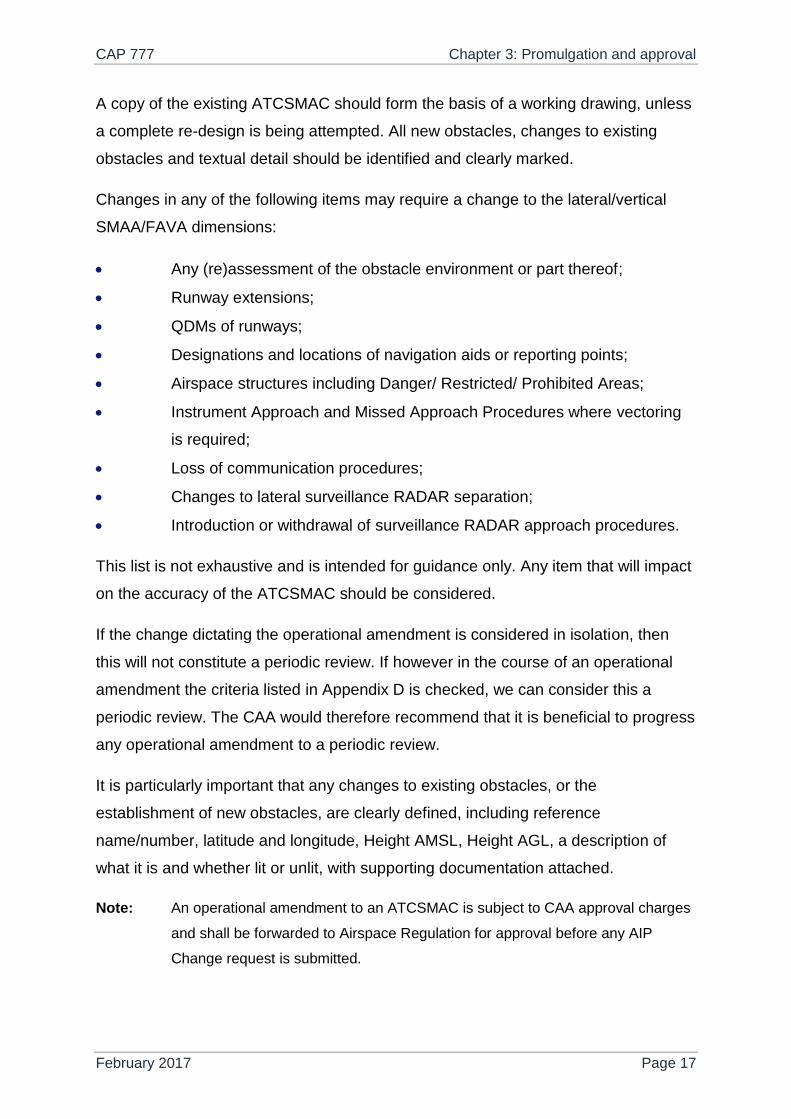
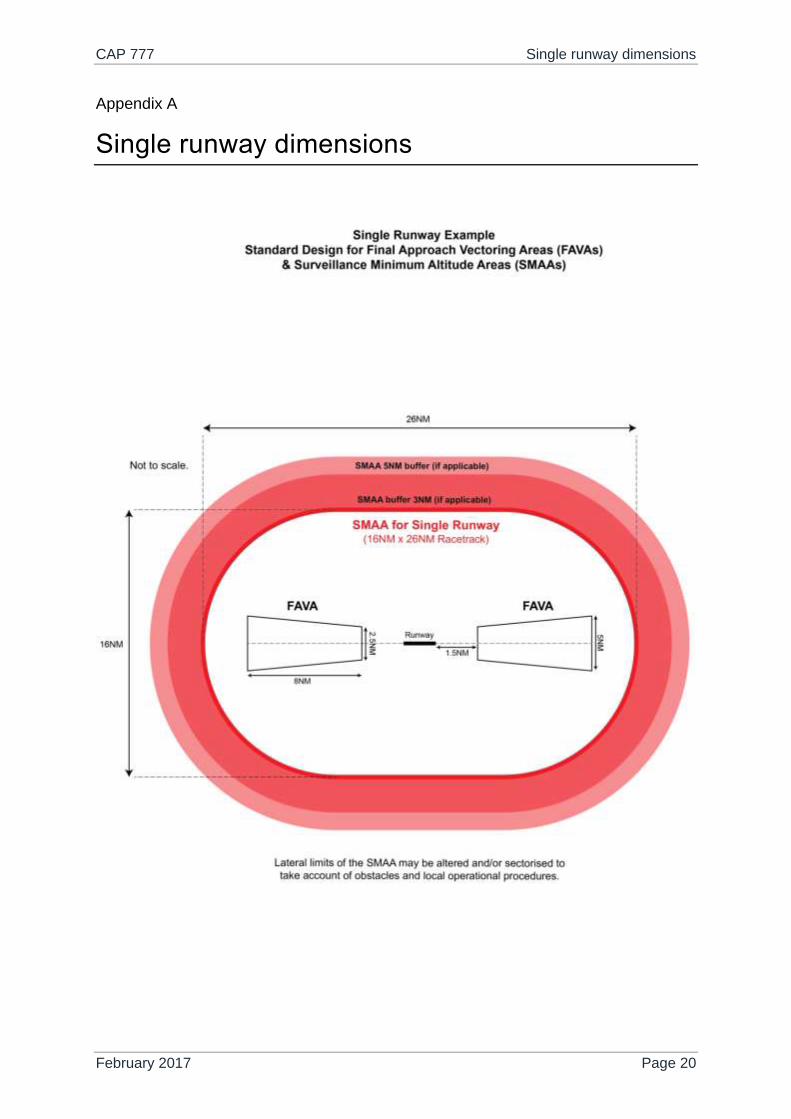
The dimensions of the nominal standard FAVAs are shown at Appendices A and B.
FAVAs should be shown for all runways where applicable, however, to simplify the
ATCSMAC, FAVAs need not be shown if there is no difference between the
minimum levels depicted and that of the SMAA itself.
Terrain clearance criteria
The minimum altitude available to ATC for vectoring arriving flights within an SMAA
sector is 300m (984ft) above the highest (dominant) obstacle.
To determine the minimum altitude available within an SMAA sector, all obstacles
within the sector and the extended Primary SMAA buffer (PSB) should be identified.
The width of the PSB is dependent on the Surveillance RADAR lateral separation
certified for use with the ATCSMAC, i.e. 3NM or 5NM. The PSB also requires a full
Minimum Obstacle Clearance (MOC) value of 300m (984ft).
The addition of 300m (984ft) feet to the elevation of the highest obstacle within the
resultant area will determine the minimum initial altitude available. The resultant
figure is then rounded up to the next (higher) 100ft interval. See Appendix C.
Where operationally desirable, the SMAA may be split into two or more sectors to
provide relief from obstacles that would affect only one runway circuit direction. A
complex sector arrangement which might be difficult for flight crew or controllers to
assimilate should be avoided.
Instrument Approach Procedure (IAP) Minimum Sector Altitudes (MSAs) shall be
shown on the ATCSMAC to indicate the minimum level that should be attained by
CAP 777 Chapter 1: General principles
February 2017 Page 6
aircraft intentionally leaving the SMAA. The ATCSMAC shall state which reference
Navaid is utilised by the IAPs to ascertain the MSAs. If an airport has multiple
procedures referenced to differing reference Navaids then the highest MSA values
are to be applied.
Contingency ATCSMAC planning
Occasionally an outage, withdrawal or reduction of an airport's Surveillance RADAR
service may occur.
Short-term unplanned outages are not considered within the remit of this document.
In such situations the ATCSMAC is invalid and the Sponsor will apply locally
specified contingency procedures. However, the Sponsor is required to inform
Airspace Regulation if a short-term unplanned outage is likely to continue for an
extended period. If this is the case, the contingency plans for planned long-term
outages as detailed below should be adopted.
Outages that may occur due to the renewal or replacement of equipment are likely to
extend over a prolonged period. In such instances it may be operationally
undesirable to revert to the published MSA. Consequently the Sponsor may consider
the implementation of a contingency ATCSMAC plan if an alternative, appropriate
Surveillance RADAR facility is available for the duration of the outage.
These longer-term outages will require careful planning and Airspace Regulation
should be notified at the earliest opportunity, so as to assist in the implementation of
a contingency ATCSMAC plan. Notification at least six months prior to the planned
suspension of an existing ATCSMAC is required.
In the first instance the promulgation of a NOTAM should be the preferred method of
notifying a temporary suspension of the current ATCSMAC in the UK AIP. This
should suffice if the impact of the outage on the ATCSMAC is minimal e.g. the
physical extents of the SMAA/s remain unchanged, but the minimum initial altitudes
are raised.
If it is considered that a NOTAM will not be sufficient to impart the required level of
detail and situational awareness e.g. multiple changes in SMAA boundaries, then it

CAP 777 Chapter 1: General principles
February 2017 Page 7
will be necessary to issue an AIP Supplement for the duration of the suspension of
the existing ATCSMAC
UK AIP Supplements containing contingency ATCSMACs plans must include:
Nature of the outage;
Proposed implementation and end dates;
Contingency SMAA chart;
Other information the Sponsor or Airspace Regulation deems relevant to
the submission.
CAP 777 Chapter 2: Design and specification
February 2017 Page 8
Chapter 2
Design and specification
Nominal standard dimensions
The dimensions of the SMAA should cover the airspace within which it is likely that
controllers will be vectoring arriving flights.
For single instrument runway aerodromes, the nominal standard lateral shape is a
racetrack area, 26NM long and 16NM wide, centred on the Aerodrome Reference
Point (ARP). For multi instrument runway aerodromes, a circular SMAA of radius 15
NM, centred on the ARP, is considered appropriate. See Appendices A and B.
When operationally desirable, the nominal standard dimensions may be modified or
adapted to provide optimum ATC vectoring profiles with regard to local terrain, traffic
flows and airspace arrangements.
SMAAs may include sectors to provide relief from dominant obstacles that may be
pertinent to only one runway circuit direction.
Design principles
SMAA
The basic principal is to draw circles of (3NM or 5NM radii dependent on Radar
Approval) around all significant obstacles or terrain within an SMAA sector and apply
the MOC. The Minimum Altitude will be: the dominant (highest) obstacle in sector +
300m (984ft) rounded up to the next (higher) 100ft interval. For the purposes of
establishing the Minimum Altitude, obstacles within the PSB are also included.
Irrespective of the chosen dimensions of the SMAA/s, it is the Sponsor’s
responsibility to provide (via their contracted APD) WGS 84 Latitude and Longitude
coordinates of the lateral limits. If a design is bespoke, the rationale behind the
lateral limits will be required.
CAP 777 Chapter 2: Design and specification
February 2017 Page 9
SMAA sub-sectors
Any additional SMAA sub sectors can be defined as radius arcs from the dominant
obstacle (3NM or 5NM) however, in complex terrain situations, or where a number of
fixed obstructions are adjacent to one another, it may be necessary to create a sub
sector that links the boundaries of arcs drawn around the obstructions. This may
result in a curved or irregular SMAA sub sector boundary and it may be more
appropriate to create a larger/simplified sub sector depicted with straight lines. These
sub sectors should be defined by WGS 84 Latitude and Longitudes.
Consideration also should be given to any detail that may confer operational
advantages and which may further affect the shape, size and internal levels of the
SMAA sectors such as:
High or challenging terrain;
Analysis of existing/future routes and airspace;
The surveillance equipment in use and its performance;
Local relevant procedures that might affect vectoring;
Surveyed aerodrome data, terrain data and vertical obstructions within 30
NM of the unit;
Any obstacles under development (e.g. tall building development or
erection of radio masts, etc.);
FAVA
If it is necessary to descend aircraft below the minimum altitude specified for the
SMAA Sector prior to the Final Approach Fix (FAF), then FAVAs will need to be
specified for each applicable runway. The default dimensions of the FAVAs are
shown at Appendices A and B. This default specification is suitable for most
applications; however as with the SMAAs this may not be appropriate in all cases
and bespoke dimensions can be applied.
Within the FAVA, a reduced clearance of 150m (492ft) above the dominant obstacle
shall be applied and this figure will be rounded up to the nearest hundred feet. It
should be noted that this is a minimum altitude to be allocated according to ICAO
and the Sponsor is free to publish a different (higher) altitude depending the actual
altitudes that will be allocated at the Aerodrome.

CAP 777 Chapter 2: Design and specification
February 2017 Page 10
In order to simplify the design of a SMAA, FAVAs need not be shown if their
respective minimum altitudes are the same as the SMAA it is situated within.
MSA
In order to validate the Minimum Sector Altitudes (MSAs) associated with any
promulgated Instrument Approach Procedures (IAPs), a circle of radius 30NM
(equates to IAC promulgated MSA of 25NM + 5NM buffer) should be drawn, centred
on the appropriate Navaid or ARP. The area encompassed by this circle should be
inspected for significant obstructions. If there are published IAPs based on NAV
AIDs, which are off the airfield, the MSAs for these facilities should also be
considered. The purpose of calculating all appropriate MSAs is to establish a single
set of MSAs for all Instrument Flight Procedures (IFPs) relative to the aerodrome, in
accordance with ICAO Document 8168 PANS OPS, Volume II, Part One Section 4,
Chapter 8 Page I-4-8-3.
Once calculated the highest MSA for each specific quadrant is used to produce a
single set of values. For example, if three MSAs are calculated for the North East
quadrant as 2300 ft, 2200 ft and 2500 ft; then 2500 ft will be used on all relevant IFP
charts.
Obstacle data
There are 3 main sources of obstacle data required for ATCSMAC design/review:
CAP 232 Aerodrome Survey – This contains an annually updated list of
significant obstacles in the vicinity of the airfield. This data is owned by the
Aerodrome Licence Holder.
Digital Vertical Obstruction File (DVOF) – This contains details of
obstacles across the whole UK. The data to a minimum of 30NM from the
Airport will be required. It is supplied routinely to all APDs by Defence
Geographic Centre (DGC) Feltham.
Terrain Data – Although a good starting point, the UK CAA Topographic
VFR 1:250,000 charts are updated infrequently and further obstacle data
sources should be utilised. These Data sources should be detailed in the
submission. The UK Ordnance Survey provide (free of charge) various
CAP 777 Chapter 2: Design and specification
February 2017 Page 11
mapping and terrain data and numerous data sets are available for
purchase.
Other design considerations
Prohibited Areas, Restricted Areas (including HIRTAs and Gas Venting Sites) or
Danger Areas within the SMAA may also affect its design, although are not
considered 'hard objects' or obstacles.
It may not be practicable or desirable to present all ATCSMAC data to the users of
the surveillance equipment. A balance must be struck between providing sufficient
information for the service to be provided safely and effectively, whilst avoiding
display clutter.
It remains the Sponsor’s responsibility to assess any changes in the surveillance
displays, in accordance with their safety management system, to ascertain the
appropriate level of detail to provide a safe and effective surveillance service.
Specifications
Published ATCSMACs are available to view online in the relevant AD 2 section of
the UK AIP. The UK specification for ATCSMACs conforms to the ICAO charting
requirements (ICAO Annex 4, Chapter 21). For any amendment, the existing chart
should form the basis of the submission. For any new design, the following standard
format forms the basis of what should be submitted. This will assist the NATS AIS
Publications Team who are ultimately responsible for producing the final Chart for
AIP Publication.
In the header & footer each ATCSMAC contains the airport name and carries the
relevant UK AIP AD 2 page reference, including date of publication. The AIRAC
publication cycle reference is also shown, together with the date of origin for the
aeronautical information. Brief details of the latest changes will also be shown.
The ATCSMAC is then split into the following areas:

CAP 777 Chapter 2: Design and specification
February 2017 Page 12
Chart
A scaled chart depicting the SMAA sector/s and FAVAs (where appropriate) with a
solid heavy line. No fixed scale is required for the chart as long as the SMAA sectors
comfortably fit within the chart area (17cm Width). The minimum altitudes will be
depicted along the inside boundary of the SMAAs/FAVAs.
The MSAs outside the SMAA will be detailed along the outside boundary of the
SMAA with each MSA sector shown as a fine solid line, with cardinal points
designated as a QDM, on the outside of the SMAA boundary.
The FAT for each runway will be shown as a fine broken line with the appropriate
runway designator.
Radio navigation facilities shall be shown by standard ICAO symbols and bearings
designated by medium pecked lines, where these will enable a pilot to check his
position in the event of loss of communications.
Significant obstructions and dominant spot heights shall be shown by standard ICAO
symbols.
Geographical features, such as coastlines or rivers, adjacent aerodromes and urban
conurbations will be shown if considered operationally significant. Urban areas,
where shown, shall be lightly shaded.
Prohibited, Restricted and Danger Areas will be shown and annotated with their
respective reference designator and operating level(s).
Adjacent controlled airspace boundaries, at or below 5000 ft/FL55, will be shown.
Relevant ATS Communication Frequencies are shown.
Delineation of appropriate Lat and Long coordinates around the periphery and a 10
nm scale bar for guidance.
Other information may be depicted, if considered operationally significant.
CAP 777 Chapter 2: Design and specification
February 2017 Page 13
Minimum initial altitude
Lateral dimensions of the SMAA sector/s, shown as WGS 84 Lat/Long coordinates
formatted in Deg/Min/Sec and prefixed with the respective Minimum Initial Altitudes.
Outside the SMAA
Summary of the responsibilities of ATC for terrain clearance when vectoring an
aircraft outside the SMAA sector/s;
Loss of communication procedures
Loss of communications for each runway will be shown for the two phases of the
procedure:
1. Initial approach;
2. Intermediate (Base Leg or 40°Leg) and final approach.
Loss of communications and missed approach procedures are an important textual
part of the ATCSMAC. These will relate to and conform with any procedures
associated with published IAPs for the aerodrome.
General information
The General Information box contains standard textual information appropriate to all
ATCSMACs and these are numbered for ease of reference. In some circumstances,
such as in the case of a bespoke ATCSMAC, the general information box may
contain modified or additional entries if appropriate, but will be based on the
following:
Levels Shown are based on QNH.
Only significant obstacles and dominant spot heights are shown.
The minimum levels shown within the ATC Surveillance Minimum Altitude
Area are in conformance with the Standard European Rules of the Air -
SERA.5015.
MSAs are based on obstacles and spot heights within 25 NM (+5NM
buffer) of the relevant Navaid.
Controlled airspace with a base in excess of 5000 ft or FL55, as
appropriate, is not shown.
CAP 777 Chapter 2: Design and specification
February 2017 Page 14
The chart may only be used for cross-checking of altitudes when in receipt
of an ATC Surveillance service.
(If Applicable) When vectoring an aircraft within the Final Approach
Vectoring Area descent clearance below the SMAA to the FAVA altitude
may only be issued if the aircraft is either established on the final
approach track or on an intercept of 40° or less, and in the case of
instrument approaches other than SRA is cleared to intercept the final
approach track.
CAP 777 Chapter 3: Promulgation and approval
February 2017 Page 15
Chapter 3
Promulgation and approval
The (re)publication of an ATCSMAC will be triggered by 1 of 4 scenarios, each of
which is further described.
1. A new ATCSMAC request
2. A periodic review
3. An operational amendment
4. A non-operational amendment
New ATCSMAC chart request
See specifications for details of what is required in terms of chart content. It should
include as a minimum: accurate latitude & longitude marks, significant and dominant
obstacles, clearly defined SMAA/FAVA boundaries and associated annotations.
Runway centrelines should also be shown. It is good practice to view other published
ATCSMACs in the UK AIP before creating a new chart.
The new drawing and any accompanying documents are to be supplied to Airspace
Regulation who will, as part of the approval process, check the SMAAs and FAVAs
to ensure the minimum altitudes are appropriate to the obstacle environment. All
other detail on the chart is the responsibility of the Sponsor.
The dominant obstacle which determines the minimum altitude of each sector should
be clearly identified, including reference name/number, latitude and longitude, Height
AMSL, Height AGL, a description of what it is and whether lit or unlit.
The submission should also be accompanied by a completed copy of the ATCSMAC
Review Sheet (see Appendix D).
Once the submission has been approved by the CAA, it is the responsibility of the
Sponsor to submit the AIP change request relating to the ATCSMAC.

CAP 777 Chapter 3: Promulgation and approval
February 2017 Page 16
The NATS AIS Publications team will forward a proof copy of the ATCSMAC to the
Sponsor for final acceptance before the publication date.
Note: A new ATCSMAC is subject to CAA approval charges and shall be forwarded to
Airspace Regulation for approval before any AIP Change request is submitted.
Periodic review at an interval not exceeding 5 years
To ensure the safe operational application of their SMAA, it is the responsibility of
the Sponsor to complete a periodic review at an interval of not more than 5 years to
cover every element on the ATCSMAC. This review shall be aligned with the review
of other Instrument Flight Procedures relative to the aerodrome. This review should
re-source and re-apply all obstacle data and check all the areas that are listed in
Appendix D.
Appendix D shall accompany all reviews to assist the identification of any necessary
changes.
If, during a periodic review it is decided that there are no changes to the ATCSMAC,
a completed Appendix D certifying that a review has been conducted is still required.
The Appendix D shall be dated accordingly and submitted by email by the Sponsor.
Reviews shall be sent to [email protected].
Note: A periodic ATCSMAC review is subject to CAA approval charges and shall be
forwarded to Airspace Regulation for approval before any AIP Change request is
submitted.
Operational amendment
The Sponsor shall, if appropriate, independently re-issue the ATCSMAC as soon as
possible if the changing obstacle environment or Aerodrome operational requirement
dictates an amendment to the SMAAs or FAVAs, either laterally or vertically. See
also Contingency in Chapter 1.
CAP 777 Chapter 3: Promulgation and approval
February 2017 Page 17
A copy of the existing ATCSMAC should form the basis of a working drawing, unless
a complete re-design is being attempted. All new obstacles, changes to existing
obstacles and textual detail should be identified and clearly marked.
Changes in any of the following items may require a change to the lateral/vertical
SMAA/FAVA dimensions:
Any (re)assessment of the obstacle environment or part thereof;
Runway extensions;
QDMs of runways;
Designations and locations of navigation aids or reporting points;
Airspace structures including Danger/ Restricted/ Prohibited Areas;
Instrument Approach and Missed Approach Procedures where vectoring
is required;
Loss of communication procedures;
Changes to lateral surveillance RADAR separation;
Introduction or withdrawal of surveillance RADAR approach procedures.
This list is not exhaustive and is intended for guidance only. Any item that will impact
on the accuracy of the ATCSMAC should be considered.
If the change dictating the operational amendment is considered in isolation, then
this will not constitute a periodic review. If however in the course of an operational
amendment the criteria listed in Appendix D is checked, we can consider this a
periodic review. The CAA would therefore recommend that it is beneficial to progress
any operational amendment to a periodic review.
It is particularly important that any changes to existing obstacles, or the
establishment of new obstacles, are clearly defined, including reference
name/number, latitude and longitude, Height AMSL, Height AGL, a description of
what it is and whether lit or unlit, with supporting documentation attached.
Note: An operational amendment to an ATCSMAC is subject to CAA approval charges
and shall be forwarded to Airspace Regulation for approval before any AIP
Change request is submitted.

CAP 777 Chapter 3: Promulgation and approval
February 2017 Page 18
Non-operational amendment
An ATCSMAC should be independently re-issued by the Sponsor at the next
available AIRAC date if the background detail on the chart is amended.
A copy of the existing ATCSMAC should form the basis of any working drawing
supplied. Examples of background detail:
Minor amendment of individual obstacles where it can be clearly proven
that there is no impact on the SMAAs or FAVAs;
Withdrawal or relocation of SMAA sector reference Navaid;
Changes to Airport characteristics, e.g. removal of instrument runways;
Airspace captured within the chart window;
Airfields captured within the chart window.
This list is not exhaustive and is intended for guidance only. Any item that will impact
accuracy or content of the ATCSMAC should be considered.
While submitting a non-operational change it is good practice to check all the non-
operational criteria listed in section 3a/3b of Appendix D (review check list) to ensure
no other details require amendment.
Note: A non-operational Amendment to an ATCSMAC does not require approval from
Airspace Regulation and an AIP change request form can be directly submitted.
Summary
The Sponsor is responsible for ensuring both accurate information and timely
amendment in relation to their ATCSMAC as published in the UK AIP.
The chart should be periodically reviewed in conjunction with other IFPs.
Any new chart request, periodic review or operational amendment shall be
performed by an APD.
Before submitting any changes via the UK AIP change request form, the Airspace
Regulation section of UK CAA will need to approve any new chart requests, periodic
reviews or operational amendments. This will attract a charge as per the IFP scheme

CAP 777 Chapter 3: Promulgation and approval
February 2017 Page 19
of charges and payment should be submitted (as per other IFP approval requests)
using DAP 1917.
ATCSMACs that require non-operational amendment do not need to be performed
by an APD, do not require approval from the CAA and do not attract a charge from
the CAA.
Where CAA approval is required, as a minimum, the following shall be sent to
Drawing with SMAA/FAVA accurately plotted and any new or amended
Lat/Longs supplied;
Current obstacles and high terrain plotted with source data referenced;
Dominant obstacles for each SMAA/FAVA clearly identified;
Minimum Altitudes for each SMAA/FAVA calculated.
After the UK AIP Change request has been submitted, the NATS AIS Publication
Team will forward the final ATCSMAC draft to the Sponsor (Cc to Airspace
Regulation) for acceptance.
If Airspace Regulation are made aware of errors on a particular ATCSMAC they will
inform the Sponsor that the chart will need urgent review. If the error is considered to
be of a safety critical nature, a NOTAM will be required to suspend the ATCSMAC
with immediate effect until the required changes are promulgated by the airfield.
See Appendix E for ATCSMAC promulgation workflow diagram.
CAP 777 Single runway dimensions
February 2017 Page 20
Appendix A
Single runway dimensions
CAP 777 Multiple runway dimensions
February 2017 Page 21
Appendix B
Multiple runway dimensions

CAP 777 Terrain clearance and lateral sectorisation
February 2017 Page 22
Appendix C
Terrain clearance and lateral sectorisation
CAP 777 ATCSMAC review / amendment sheet
February 2017 Page 23
Appendix D
ATCSMAC review / amendment sheet
Appendix D available from publication page,
www.caa.co.uk/CAP777

CAP 777 ATCSMAC promulgation workflow
February 2017 Page 24
Appendix E
ATCSMAC promulgation workflow
Periodic reviewPeriodic reviewNew chartNew chart AmendmentAmendment
Sponsor
contracts APD
New ATCSMAC
designed by APD
for Sponsor
P
APD reviews
operational*
ATCSMAC
content
P
Sponsor reviews
non-
operational**
ATCSMAC
content
P
Sponsor collate
and supply
information to
CAA
CAA approval of
operational*
content, CAA
charge applicable
Sponsor submits
AIP change
request
NATS AIS incorporate
amendments and update
‘background’ content of chart.
Final version sent to Sponsor and
CAA for final acceptance prior to
publication
Publish on
agreed AIRAC
date
Sponsor
identifies
requirement
Sponsor aware of
change
Operational*
amendment?
Non-
operational**
amendment?
Sponsor
contracts APD to
calculate the
operational*
amendment
O
Sponsor collates
detail of the non-
operational**
ATCSMAC
amendment
O
APD calculates
operational*
amendment
Sponsor aware of
review
requirement
Sponsor
contracts APD to
carry out
ATCSMAC
review!
No
t ap
pro
ved
No
t app
roved
CAA approval not required. No CAA charge.
*Operational – Content relates to the lateral
extents or minimum altitudes of the SMAAs
and FAVAs.
**Non-operational – Content relates to all other
chart and textual content, such as frequencies,
transition altitude, loss of communications,
general information and background chart
content.
P – This fulfils the periodic review
requirement.
O – This does not fulfil the periodic review
requirement.
! – CAA recommends progressing any
operational amendment to a periodic review.
Sponsor action
CAA action
APD action
NATS AIS
action