low altitude surveillance...
TRANSCRIPT
Low Altitude Surveillance Blimp
Capstone Senior Design Proposal EE 499
March 8, 2007
Jordan Dressman [email protected]
Tyler Doering [email protected]
Matt Ohlmann [email protected]
Corbin Williams [email protected]
Dr. Osamah Rawashdeh [email protected]
March 8, 2007 EE 499 – Capstone Senior Design Report
Section 1.2 – Abstract ......................................................................................................... 3 Section 1.3 – Introduction................................................................................................... 3 Section 1.4 – Background................................................................................................... 3 Section 1.5 – Impact Statement .......................................................................................... 3 Section 1.6 – Technical Description ................................................................................... 3
Section 1.6.1 – Blimp...................................................................................................... 4 Section 1.6.2 – Blimp Payload........................................................................................ 5 Section 1.6.3 – Ground Station....................................................................................... 7
Section 1.7 – Timeline ...................................................................................................... 10 Section 1.7.1 – Blimp Payload System Timeline ......................................................... 10 Section 1.7.2 - Ground Station System Timeline ......................................................... 10 Section 1.7.2 – Papers and Presentations Timeline ...................................................... 10
Section 1.8 – Distribution of Effort .................................................................................. 10 Section 1.8.1 – Blimp Payload System Efforts............................................................. 11 Section 1.8.2 – Ground Station System Efforts ............................................................ 11
Section 1.9 – Deliverables ................................................................................................ 11 Section 1.10 – Summary of Project .................................................................................. 11 Section 1.11 – Budget Parts List....................................................................................... 12 Section 1.12 – Acknowledgements................................................................................... 12 Section 1.13 – Biographical Sketches............................................................................... 12
Section 1.13.1 – Jordan Dressman................................................................................ 13 Section 1.13.2 – Tyler J. Doering ................................................................................. 13 Section 1.13.3 – Matt W. Ohlmann .............................................................................. 13 Section 1.13.4 – Corbin E. Williams ............................................................................ 13 Section 1.13.5 – Dr. Osamah A. Rawashdeh................................................................ 13
2 of 16
March 8, 2007 EE 499 – Capstone Senior Design Report
Section 1.2 – Abstract
This relatively light-weight, tethered, low-altitude blimp will incorporate a payload that wirelessly communicates with a corresponding ground station. The payload will consist of a pan and tilt camera, wireless data radio link, video transmitter, and sensor system. The camera will be controlled from a ground station, and live video feed from the camera will be streamed to the ground such that the environmental conditions obtained from the sensor will overlay the video in text.
Section 1.3 – Introduction
Low-altitude blimps have been successfully designed and implemented for several years. These blimps may be used for tasks anywhere from radar detection of missiles to surveillance tactics or for acquiring environmental conditions. The design and implementation of a low-altitude launched surveillance platform will serve many beneficial purposes for both eager learning college students and the community as well.
Section 1.4 – Background
Thoughts pertaining to unmanned aerial surveillance vehicles, such as the proposed low-altitude surveillance blimps, have only recently become entirely successful thanks to the complex technologies of today’s world. The several components that combine to achieve a low-altitude surveillance blimp make more sense than stationary, elementary surveillance methods of the past such as commercial aerial photography, sporting events, real estate site surveys, and archaeological observations.
Section 1.5 – Impact Statement Although the war against terrorism seems to increase daily, luckily our
government seems to always respond with new and innovative technologies. One may easily infer that acquiring information regarding an enemy will definitely be less dangerous through a UAV (Unmanned Air Vehicle) with surveillance technology versus the more primitive tactic of sending soldiers on the ground where they are more likely susceptible to danger. In fact, the army uses small remote control airplanes to obtain desired information about their enemies. Obviously the worst thing that could happen with this surveillance method would be the loss of the remote control device and a failed attempt of retrieving information, a much better scenario than the possible loss of human life that could occur if actual soldiers would have been caught trying to survey the same area of interest. Concluding, the reason for the design and implementation of a low altitude surveillance blimp is because it easily utilizes existing technologies.
Section 1.6 – Technical Description
This section of the document provides a technical overview for the payload system that will be attached to the blimp, and an overview of the ground station. The payload systems pertaining to the blimp consist of a power system, a microcontroller,
3 of 16
March 8, 2007 EE 499 – Capstone Senior Design Report
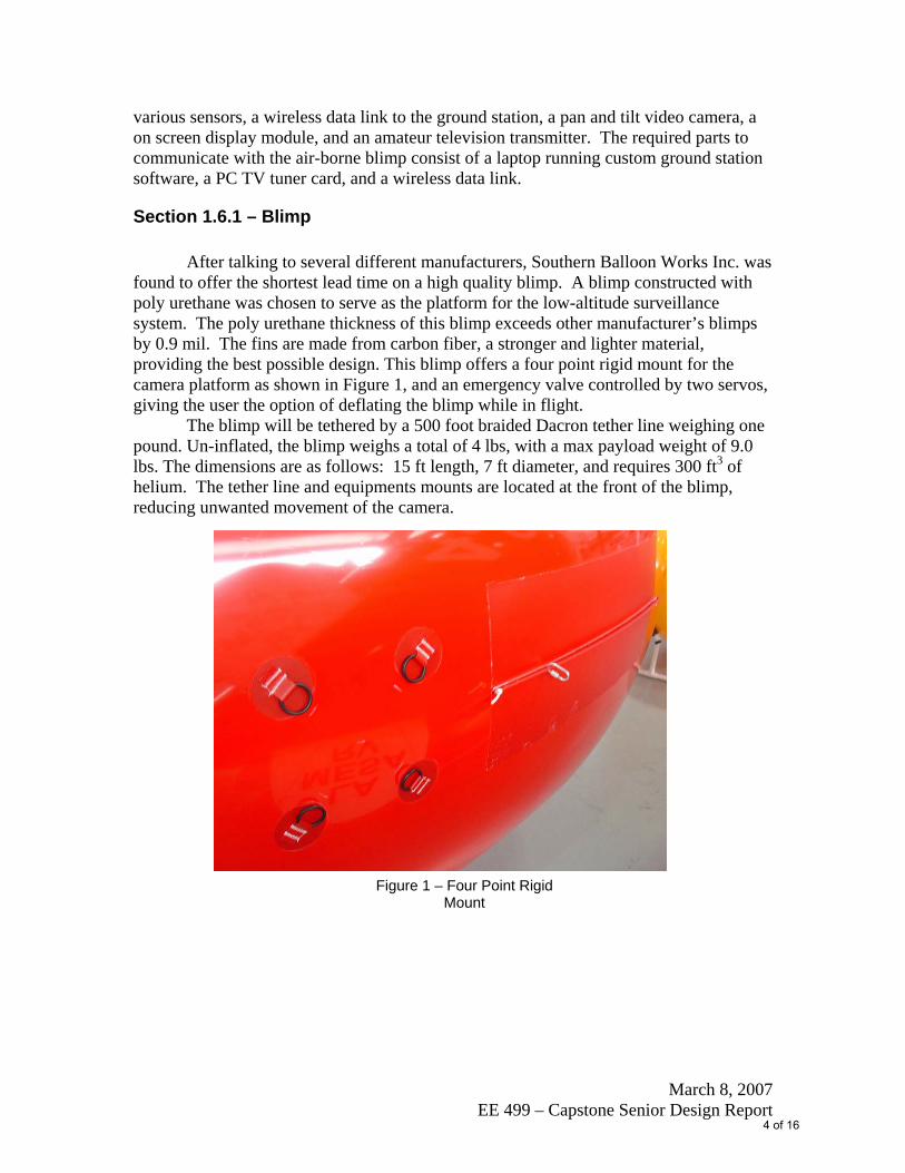
Figure 1 – Four Point Rigid Mount
various sensors, a wireless data link to the ground station, a pan and tilt video camera, a on screen display module, and an amateur television transmitter. The required parts to communicate with the air-borne blimp consist of a laptop running custom ground station software, a PC TV tuner card, and a wireless data link.
Section 1.6.1 – Blimp
After talking to several different manufacturers, Southern Balloon Works Inc. was found to offer the shortest lead time on a high quality blimp. A blimp constructed with poly urethane was chosen to serve as the platform for the low-altitude surveillance system. The poly urethane thickness of this blimp exceeds other manufacturer’s blimps by 0.9 mil. The fins are made from carbon fiber, a stronger and lighter material, providing the best possible design. This blimp offers a four point rigid mount for the camera platform as shown in Figure 1, and an emergency valve controlled by two servos, giving the user the option of deflating the blimp while in flight.
The blimp will be tethered by a 500 foot braided Dacron tether line weighing one pound. Un-inflated, the blimp weighs a total of 4 lbs, with a max payload weight of 9.0 lbs. The dimensions are as follows: 15 ft length, 7 ft diameter, and requires 300 ft3 of helium. The tether line and equipments mounts are located at the front of the blimp, reducing unwanted movement of the camera.
4 of 16
March 8, 2007 EE 499 – Capstone Senior Design Report
Section 1.6.2 – Blimp Payload
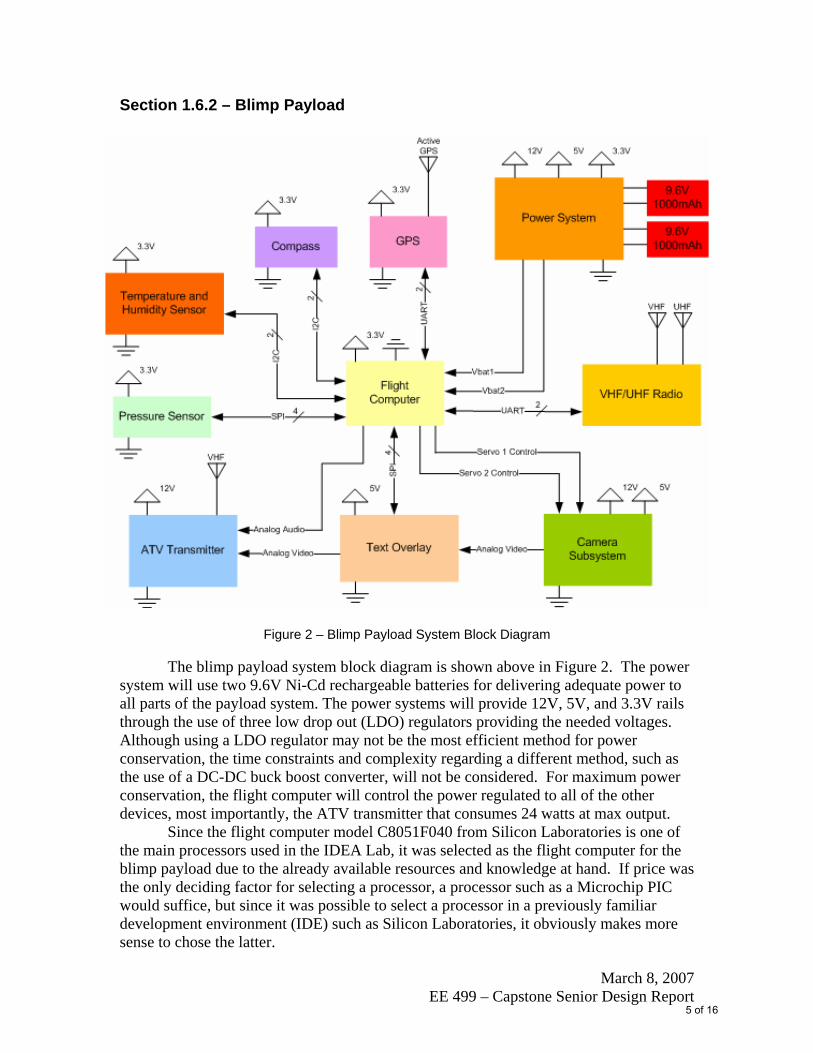
Figure 2 – Blimp Payload System Block Diagram
The blimp payload system block diagram is shown above in Figure 2. The power
system will use two 9.6V Ni-Cd rechargeable batteries for delivering adequate power to all parts of the payload system. The power systems will provide 12V, 5V, and 3.3V rails through the use of three low drop out (LDO) regulators providing the needed voltages. Although using a LDO regulator may not be the most efficient method for power conservation, the time constraints and complexity regarding a different method, such as the use of a DC-DC buck boost converter, will not be considered. For maximum power conservation, the flight computer will control the power regulated to all of the other devices, most importantly, the ATV transmitter that consumes 24 watts at max output.
Since the flight computer model C8051F040 from Silicon Laboratories is one of the main processors used in the IDEA Lab, it was selected as the flight computer for the blimp payload due to the already available resources and knowledge at hand. If price was the only deciding factor for selecting a processor, a processor such as a Microchip PIC would suffice, but since it was possible to select a processor in a previously familiar development environment (IDE) such as Silicon Laboratories, it obviously makes more sense to chose the latter.
5 of 16
March 8, 2007 EE 499 – Capstone Senior Design Report
The Kenwood TH-D7AG VHF/UHF hand held ham radio was selected primarily because it is the only hand held radio on the market with a built-in TNC and is capable of having a stand alone power of up to 3 hours at average usage. It has an independent power source and transmits/receives at an average distance of 100 miles.
The sensor system on the blimp will consist of the following sensors: a global positioning satellite receiver, a compass, a temperature and humidity sensor, and a pressure sensor. Due to the complexity and time required to design a GPS sensor, the Lassen iQ GPS sensor from Trimble was chosen as an off the shelf module that provides real time highly accurate longitude, latitude, and altitude information. The Lassen iQ GPS sensor is the smallest in weight and consumes an ultra low power amount of 86mW, smaller in comparison to any other Trimble products on the market. The compass chosen was the HMC6352 from Honeywell because it is the only complete on chip digital compass on the market and is compatible with the I2C digital interface. The temperature and humidity sensor is the SHT15 from Sensirion, also chosen because of the I2C digital interface. The pressure sensor SCP1000-D01, from VTI technologies, was chosen because it is the only MEMs base pressure sensor on the market with an SPI interface and a 17 bit resolution.
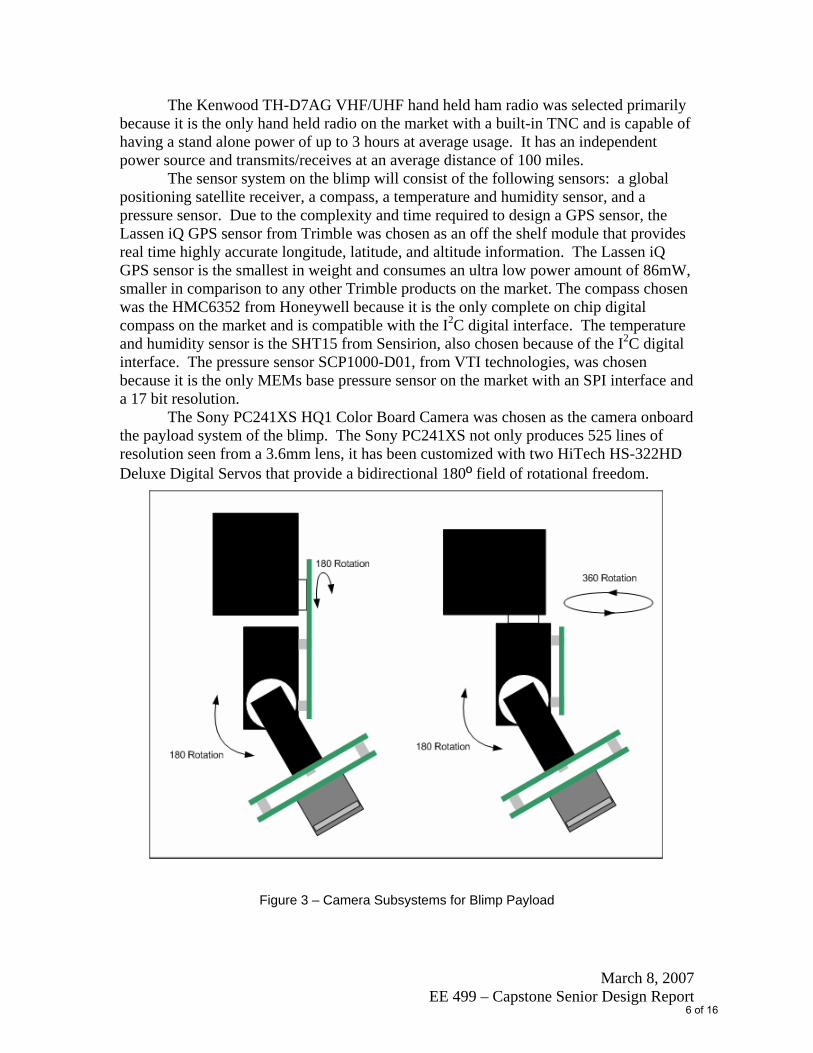
The Sony PC241XS HQ1 Color Board Camera was chosen as the camera onboard the payload system of the blimp. The Sony PC241XS not only produces 525 lines of resolution seen from a 3.6mm lens, it has been customized with two HiTech HS-322HD Deluxe Digital Servos that provide a bidirectional 180º field of rotational freedom.
Figure 3 – Camera Subsystems for Blimp Payload
6 of 16
March 8, 2007 EE 499 – Capstone Senior Design Report
As shown in the above Figure 3, one may easily see how the desired pan and tilt features are acquired through the combination of these two digital servos and Sony camera acting as a gimble. The gimble on the left of Figure 3 was assembled with two 180º servos and has been chosen despite the gimble on the right that provides 360º of rotation. These servos were free and have been modified to enable all necessary camera movements. Finally, having the capability to interchange the 3.6 mm lens with larger lenses up to 25 mm in size, the camera subsystem is able to obtain all desired fields of view for any heights the blimp will inhabit.
The off the shelf module BOB-4 was chosen because it is a low-cost video information overlay module that allows a corresponding microcontroller or PC to display text on standard TV monitors. This module generates background video on-board combined with printable characters and commands controlled through SPI or RS-232 style data links. Both NTSC and PAL video standards are supported by BOB-4. BOB-4 has dimensions of 3.50 x 1.05 x 0.35 inches and weighs about 0.35oz. Ambient operating temperature range is 0-50C.
The MFJ-8709 5W ATV Transmitter module was chosen to accept an NTSC video signal and generate a corresponding RF signal modulated with all combined components of the payload system. The signal can be received on any standard TV receiver fitted with a suitable RF down-converter capable of tuning to the desired frequency. Also, a built in video and audio test signal generator is provided for testing purposes, one very beneficial accommodation pertaining to this module. The power consumption of this module at max output is 24 watts. The power output of the transmitter can be adjusted, making it feasible for the payload system on the blimp.
Section 1.6.3 – Ground Station
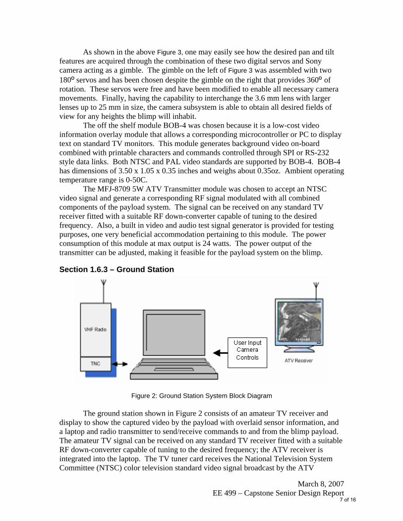
Figure 2: Ground Station System Block Diagram
The ground station shown in Figure 2 consists of an amateur TV receiver and display to show the captured video by the payload with overlaid sensor information, and a laptop and radio transmitter to send/receive commands to and from the blimp payload. The amateur TV signal can be received on any standard TV receiver fitted with a suitable RF down-converter capable of tuning to the desired frequency; the ATV receiver is integrated into the laptop. The TV tuner card receives the National Television System Committee (NTSC) color television standard video signal broadcast by the ATV
7 of 16
March 8, 2007 EE 499 – Capstone Senior Design Report
transmitter aboard the blimp and must have a composite RCA Video output for use with the head mounted display unit.
The user input is sent to the laptop and is processed by way of a graphical user interface (GUI). The GUI is written in VisualBasic.Net (VB.Net) using the .NET 2.0 Framework. The .NET Framework is a large body of pre-coded solutions or class library to common program requirements, and also manages the execution of programs in a runtime environment known as the Common Language Runtime (CLR). The CLR isolates the application being used by the user from the computer so that the programmer does not need to worry about what platform they are writing the program for, as long as the platform can run the .NET framework it can run the program. This is very similar to the Java Virtual Machine where you write the code once and can run anywhere. The drawback is that .NET is currently only fully available on Windows platforms, whereas Java is fully available on many platforms. The .NET framework uses Just-In-Time compilers which is a method to improve the runtime performance of the program where previously virtual machines used an interpreter during runtime to compile source code to its native processor machine code. The source code is first compiled into a common intermediate language which handles the parsing and performing basic optimizations, then during runtime the CLR can convert the intermediate language into machine code much faster than if interpreting the statements directly from original source code. Furthermore, once the intermediate language is converted into machine code it can be cached so that subsequent reinterpretation of compiled code can be skipped. This will give the user an initial startup delay, but will run faster once all the code is compiled into native machine code.
Choosing the language to write this project in was based on three criteria: GUI builder, Serial Port support, and existing integrated development environments (IDE). VB.Net was chosen for this task mainly because Microsoft Visual Basic 2005 Express Edition is a great, free IDE for VB.Net including a GUI builder and debugger. Also, the .NET 2.0 Framework includes pre-written serial port functions similar to all .NET languages. VB.Net was chosen because of its understood ease in dealing with user events, such as pressing a button on a windows form, and also because of previous personal experience with the language. Other languages could have been used such as c/c++, java, or perl, but finding good GUI builders for these languages were not obvious. Java has good GUI capabilities and the eclipse IDE with a GUI builder plug-in is a good option, however the serial port functions seem to be overly complicated for java.
8 of 16
March 8, 2007 EE 499 – Capstone Senior Design Report
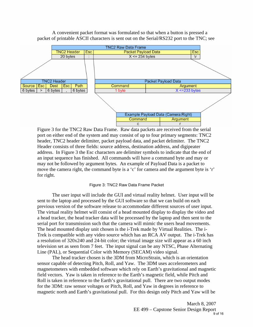
A convenient packet format was formulated so that when a button is pressed a packet of printable ASCII characters is sent out on the Serial/RS232 port to the TNC; see
Figure 3 for the TNC2 Raw Data Frame. Raw data packets are received from the serial port on either end of the system and may consist of up to four primary segments: TNC2 header, TNC2 header delimiter, packet payload data, and packet delimiter. The TNC2 Header consists of three fields: source address, destination address, and digipeater address. In Figure 3 the Esc characters are delimiter symbols to indicate that the end of an input sequence has finished. All commands will have a command byte and may or may not be followed by argument bytes. An example of Payload Data is a packet to move the camera right, the command byte is a ‘c’ for camera and the argument byte is ‘r’ for right.
Figure 3: TNC2 Raw Data Frame Packet
The user input will include the GUI and virtual reality helmet. User input will be sent to the laptop and processed by the GUI software so that we can build on each previous version of the software release to accommodate different sources of user input. The virtual reality helmet will consist of a head mounted display to display the video and a head tracker, the head tracker data will be processed by the laptop and then sent to the serial port for transmission such that the camera will mimic the users head movements. The head mounted display unit chosen is the i-Trek made by Virtual Realities. The i-Trek is compatible with any video source which has an RCA AV output. The i-Trek has a resolution of 320x240 and 24-bit color; the virtual image size will appear as a 60 inch television set as seen from 7 feet. The input signal can be any NTSC, Phase Alternating Line (PAL), or Sequential Color with Memory (SECAM) video signal.
The head tracker chosen is the 3DM from MicroStrain, which is an orientation sensor capable of detecting Pitch, Roll, and Yaw. The 3DM uses accelerometers and magnetometers with embedded software which rely on Earth’s gravitational and magnetic field vectors. Yaw is taken in reference to the Earth’s magnetic field, while Pitch and Roll is taken in reference to the Earth’s gravitational pull. There are two output modes for the 3DM: raw sensor voltages or Pitch, Roll, and Yaw in degrees in reference to magnetic north and Earth’s gravitational pull. For this design only Pitch and Yaw will be
9 of 16

March 8, 2007 EE 499 – Capstone Senior Design Report
used which can range from +/- 180o with a resolution of <.1o when aggressive digital filtering is used. The output format is in RS-232 serial with a transmission rate of 9600 baud.
Camera control data is transmitted to the payload through a bidirectional radio link. The radio data link will primarily be used to send commands to the Pan/Tilt camera but also will receive sensor data and control the Emergency Valve Release (EVR) servomotors. The EVR is a precautionary measure should we loose control of the blimp. The EVR can allow the helium to escape from the blimp so that it can be recovered to the ground. The wireless data link consists of an amateur ham radio transceiver. The ground station will use an amateur ham radio as the wireless data link, a terminal node controller (TNC) will be used to convert the serial digital communication string to the required AX.25 packets that are transmitted over the air. The laptop will communicate with the terminal node controller by way of the Serial/RS232 port.
Section 1.7 – Timeline In order to ensure the project will be finished by the required deadline, a detailed
timeline was created. This timeline will be changing everyday to account for different problems that shall be encountered. This timeline will be used to ensure that steady progress is being made toward the final goal and the final goal is met. Since the project consists of two main parts that can be worked on concurrently there are two separate timelines for the ground station and the blimp payload. A third timeline was also created to account for different presentations and different technical paper that need to be presented and written. Half way through the allocated time to finish this project all three schedules will be looked at and any de-scoping or extra features will be decided then.
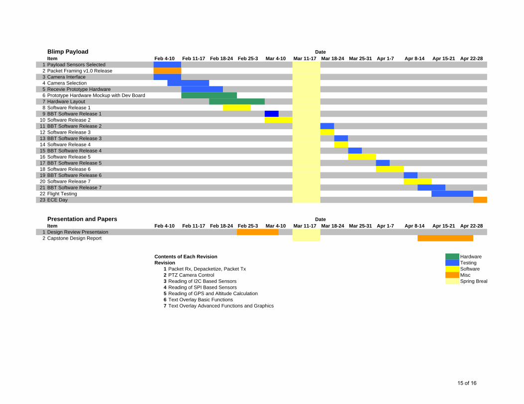
Section 1.7.1 – Blimp Payload System Timeline (Attached at the end of the document) An important note about the blimp payload
system timeline is that there will be a series of software releases that will incorporate different features. Each software release will be capable of being used as the final software with just a simplified feature set. This is to account for any schedule slippage.
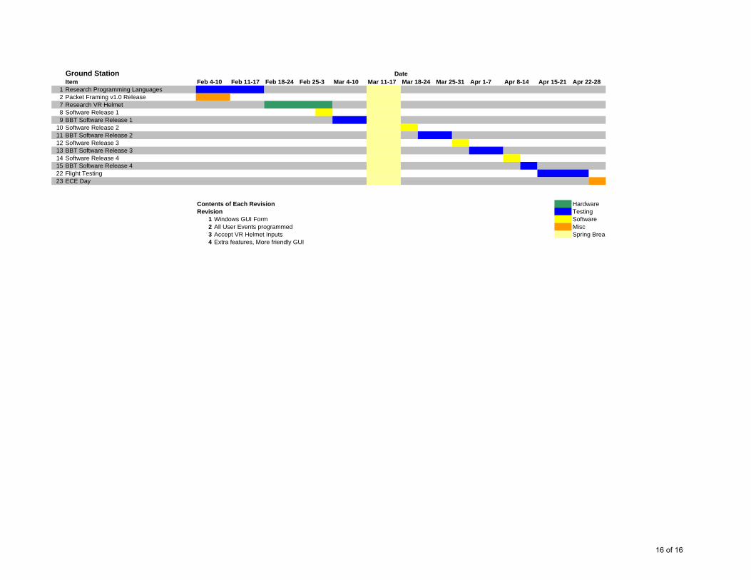
Section 1.7.2 - Ground Station System Timeline (Attached at the end of the document) An important note about the ground station
software timeline is there will be a series of releases to correspond with the timeline of the blimp software releases.
Section 1.7.2 – Papers and Presentations Timeline (Attached at the end of the document)
Section 1.8 – Distribution of Effort
10 of 16

March 8, 2007 EE 499 – Capstone Senior Design Report
Since the project is broken into two main parts, blimp payload system and ground station, the four person team will be broken into 2 groups. Tyler and Corbin will lead the effort for the blimp system payload. Jordan and Matt will lead the effort for the ground station. The entire team will be responsible for all papers and presentations.
Section 1.8.1 – Blimp Payload System Efforts
Tyler will be the lead software architect and Corbin will be responsible for the black box testing (BBT) and white box testing (WBT) for each of the individual software releases. Having a lead coder and a lead tester will allow for simultaneous coding and testing. It will also be good practice to have a person other than the coder to test the software to ensure the software is bug free.
Section 1.8.2 – Ground Station System Efforts Jordan and Matt will be in charge of writing and testing the ground software to
interface the user with the laptop and to send out serial port data to be broadcast to the PT camera. Jordan and Matt will also research on motion sensors and virtual goggles and determine a way to display the video in the goggles and update the ground software to accept motion sensor data.
Section 1.9 – Deliverables See schedules attached at the end of this document.
Section 1.10 – Summary of Project
Low-altitude blimps have been successfully designed and implemented for a long time. Upon successful completion of this low-altitude blimp launched surveillance platform, students will reap the rewards of accomplishing not just an extremely important school project, but experience first hand a project that encompasses several extremely important and fundamental electrical engineering problem solving techniques.
11 of 16

March 8, 2007 EE 499 – Capstone Senior Design Report
Section 1.11 – Budget Parts List
Shown below in Table 1 is a list of the different components and their respective manufacture part number and price.
Part Description Manufacture Manufacture P/N Price
GPS Module Trimble Lassen iQ $49.95 Active GPS Antenna Trimble 57859-00 $14.95 Digital Compass Honeywell HMC6352 $49.95 Pressure Sensor VTI Technologies SCP1000-D01 $24.95 On Screen Display Module Decade Engineering BOB-4 $99.95 ATV Transmitter MFJ Enterprises MFJ-8709 $199.95 ATV UHF Antenna Comet SMA24 $19.95 UHF/VHF Radio Kenwood TH-D7AG $329.95 Flight Computer Silicon Labs C8051F040 $13.71
15' Camera Blimp Southern Balloon Works
15' Camera Blimp $549.00
Emergency Release Valve Southern Balloon Works
Emergency Valve $100.00
Head Mounted Video Display Vrealities i-Trek $199.00 Board Camera Sony PC241XS $99.95 Orientation Sensors MicroStrain 3DM $745.00 Total $2,496.26
Table 1 – Budget and Parts List
Section 1.12 – Acknowledgements
The financial support for this project is thanks to Dr. Richard Hackney and The Kentucky Space Grant Consortium. Original project ideas and scoping is thanks the Dr. Osamah Rawashdeh. This project has been deemed successful thanks to the much appreciated support from Dr. Hackney, Dr. Rawashdeh, and the IDEA Lab.
Section 1.13 – Biographical Sketches The necessary knowledge and resources needed to successfully complete an
ambitious task such as this will inevitably test nearly every aspect of Electrical Engineering. Solving the problem for a proposed airborne surveillance platform benefits students not only by increasing their teamwork experience, but also by exposing them to the real world technologies produced from everything theoretically taught in school. The following group of four students and one advisor is the team comprised to complete the blimp project.
12 of 16

March 8, 2007 EE 499 – Capstone Senior Design Report
Section 1.13.1 – Jordan Dressman Jordan is currently a senior at the University of Kentucky of Electrical
Engineering and Computer Engineering with accompanying Mathematics and Computer Science minors. Jordan is a member of Eta Kappa Nu (HKN): Electrical and Computer Engineering Honor Society. Jordan is working in the IDEA lab; an embedded systems lab supervised by Dr. Lumpp and Dr. Rawashdeh, currently debugging machines used for Medical Research. Jordan worked two years at Toyota Motor Manufacturer of Kentucky in Georgetown, Kentucky doing electrical maintenance on production lines. Present interests include nanotechnology, quantum computing, and embedded systems.
Section 1.13.2 – Tyler J. Doering
Tyler is a senior at the University of Kentucky and is currently working towards a BS in Electrical and Computer Engineering with a minor in Computer Science. Tyler has completed four different co-op rotations at General Electric – Consumer and Industrial in Louisville Kentucky. During the four different rotations Tyler gained experience in embedded system hardware and software design. Tyler currently works in the IDEA Lab at the University of Kentucky where he does embedded systems hardware and software research for different projects and currently a member of the KySat Flight Software Team.
Section 1.13.3 – Matt W. Ohlmann Matt is currently a senior at the University of Kentucky pursuing a Bachelor’s of
Science degree in Electrical Engineering accompanied with a minor in Mathematics. Matt has had Co-op educational experience with BWXT-Y12 Nuclear Weapons Complex located in Oak Ridge, TN. Various tasks involved providing insight for the updating of various evacuation alarm systems such as ENS (Emergency Notification System) and CAAS (Criticality Accident Alarm System) under Non-Nuclear Design and Process Engineering supervision.
Section 1.13.4 – Corbin E. Williams Corbin is a senior at the University of Kentucky and is currently working towards
a BS in Electrical Engineering with a minor in Mathematics. Corbin worked in the U.S.A.F. as a Meteorological and Navigational Aids Technician performing maintenance on over 40 pieces of meteorological equipment and 15 pieces of Navigational equipment. Corbin was also the sole maintainer of 1 of the existing 13 Digital Ionosphere sounding system used in specifying the global ionosphere in real time.
Section 1.13.5 – Dr. Osamah A. Rawashdeh Dr. Rawashdeh is a Lecturer in the Department of Electrical and Computer
Engineering at the University of Kentucky. He received his BS, MS, and PhD in Electrical Engineering from the University of Kentucky in 2000, 2003, 2005 respectively.
13 of 16

March 8, 2007 EE 499 – Capstone Senior Design Report
He absolved internships at Daimler Benz AG and at SIEMENS AG and has been a member of the IDEA Lab since March 2000. He is a member of IEEE, ACM, AIAA, and ARRL. His research interests include embedded systems design, reconfigurable computing, and fault-tolerance.
14 of 16
Blimp PayloadItem Feb 4-10 Feb 11-17 Feb 18-24 Feb 25-3 Mar 4-10 Mar 11-17 Mar 18-24 Mar 25-31 Apr 1-7 Apr 8-14 Apr 15-21 Apr 22-28
1 Payload Sensors Selected2 Packet Framing v1.0 Release3 Camera Interface4 Camera Selection5 Recevie Prototype Hardware6 Prototype Hardware Mockup with Dev Board7 Hardware Layout8 Software Release 19 BBT Software Release 1
10 Software Release 211 BBT Software Release 212 Software Release 313 BBT Software Release 314 Software Release 415 BBT Software Release 416 Software Release 517 BBT Software Release 518 Software Release 619 BBT Software Release 620 Software Release 721 BBT Software Release 722 Flight Testing23 ECE Day
Presentation and PapersItem Feb 4-10 Feb 11-17 Feb 18-24 Feb 25-3 Mar 4-10 Mar 11-17 Mar 18-24 Mar 25-31 Apr 1-7 Apr 8-14 Apr 15-21 Apr 22-28
1 Design Review Presentaion2 Capstone Design Report
Contents of Each Revision HardwareRevision Testing
1 Packet Rx, Depacketize, Packet Tx Software2 PTZ Camera Control Misc3 Reading of I2C Based Sensors Spring Break4 Reading of SPI Based Sensors5 Reading of GPS and Altitude Calculation6 Text Overlay Basic Functions7 Text Overlay Advanced Functions and Graphics
Date
Date
15 of 16
Ground StationItem Feb 4-10 Feb 11-17 Feb 18-24 Feb 25-3 Mar 4-10 Mar 11-17 Mar 18-24 Mar 25-31 Apr 1-7 Apr 8-14 Apr 15-21 Apr 22-28
1 Research Programming Languages2 Packet Framing v1.0 Release7 Research VR Helmet8 Software Release 19 BBT Software Release 1
10 Software Release 211 BBT Software Release 212 Software Release 313 BBT Software Release 314 Software Release 415 BBT Software Release 422 Flight Testing23 ECE Day
Contents of Each Revision HardwareRevision Testing
1 Windows GUI Form Software2 All User Events programmed Misc3 Accept VR Helmet Inputs4 Extra features, More friendly GUI
Date
Spring Break
16 of 16