afti/f-16 digital flight control system experience dale …
TRANSCRIPT
AFTI/F-16 DIGITAL FLIGHT CONTROL SYSTEM EXPERIENCE
Dale A. Mackall NASA Ames Research Center
Dryden Flight Research Facility Edwards, California
First Annual NASA Aircraft Controls Workshop NASA Langley Research Center
Hampton, Virginia October 25-27, 1983
469
https://ntrs.nasa.gov/search.jsp?R=19840012524 2020-03-22T08:19:12+00:00Zbrought to you by COREView metadata, citation and similar papers at core.ac.uk
provided by NASA Technical Reports Server

I- II, 8.8-8 I ,,. ,. ,.. _ . - .-..---
ABSTRACT
The Advanced Fighter Technology Integration (AFTI) F-16 program is investigating the integration of emerging technologies into an advanced fighter aircraft. The three major technologies involved are the (1) triplex digital flight control system; (2) decoupled aircraft flight control; and (3) integration of avionics, pilot dis- plays, and flight control. In addition to investigating improvements in fighter per- formance, the AFTI/F-16 program provides a look at generic problems facing highly integrated, flight-crucial digital controls. An overview of the AFTI/F-16 systems is followed by a summary of flight test experience and recommendations.
470
AFTI/F-16
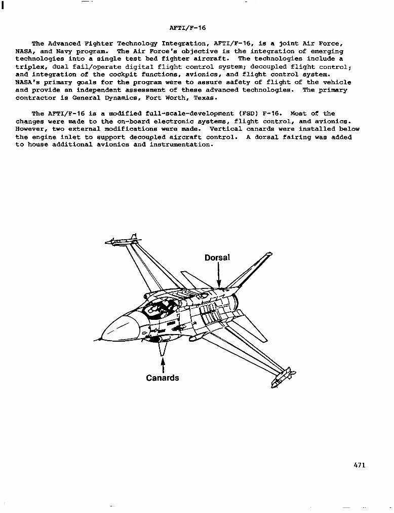
The Advanced Fighter Technology Integration, AFTI/F-16, is a joint Air Force, NASA, and Navy program. The Air Force's objective is the integration of emerging technologies into a single test bed fighter aircraft. The technologies include a triplex, dual fail/operate digital flight control system; decoupled flight control.; and integration of the cockpit functions, avionics, and flight control system. NASA’s primary goals for the program were to assure safety of flight of the vehicle and provide an independent assessment of these advanced technologies. The primary contractor is General Dynamics, Fort Worth, Texas.
The AFTI/F-16 is a modified full-scale-development (FSD) F-16. Most of the changes were made to the on-board electronic systems, flight control, and avionics. However, two external modifications were made. Vertical canards were installed below the engine inlet to support decoupled aircraft control. A dorsal falring was added to house additional avionics and instrumentation.
471

AFTI'S INTEGRATED TECHNOLOGIES
The digital flight control system is the heart of the technologies integrated into the APTI. In the area of fault tolerance, the dual fail/operate system provides dual fail/operate capability 95% of the time for computer CPU faults. Dual fail/ operate was a goal in addressing dual failures of sensors and discrete inputs for the APT1 program. The control law design includes mission-specific and decoupled-, control modes. The primary goal is to improve aircraft survivability in an attack.
Another goal to reduce pilot workload is approached by integrating avionics and flight control functions with cockpit displays. One selection of a mission phase switch configures avionics, weapons, and flight control to a specific mode. The multipurpose displays allow for a centralized information display for all systems.
These main technologies resulted in two spinoff technology goals for the flight control system, asynchronous computer operation, and a software-intensive design. Asynchronous operation is a major design characteristic which affects the dual fail/ operate capability, decoupled control law design, and the pilot's display of flight control status. The primary purpose of software-intensive design is to avoid addi- tional unique hardware in accomplishing the dual fail/operate requirement.
Dual fail/operate
with avionics
Standard 81 decoupled
Air-to-surface gun
digital flight control system Software intensive design
472
RELIABILITY AND FAULT TOLERANCE
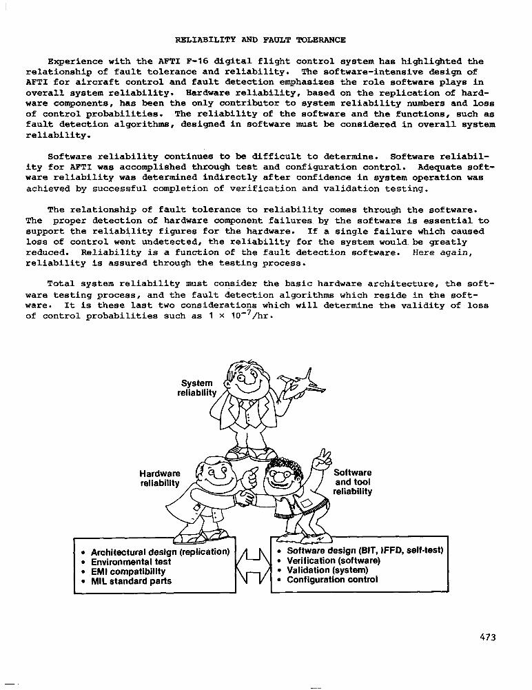
Experience with the AFT1 F-16 digital flight control system has highlighted the relationship of fault tolerance and reliability. The software-intensive design of AFT1 for aircraft control and fault detection emphasizes the role software plays in overall system reliability. Hardware reliability, based on the replication of hard- ware components, has been the only contributor to system reliability numbers and loss of control probabilities. The reliability of the software and the functions, such as fault detection algorithms, designed in software must be considered in overall system reliability.
Software reliability continues to be difficult to determine. Software reliabil- ity for AFT1 was accomplished through test and configuration control. Adequate soft- ware reliability was determined indirectly after confidence in system operation was achieved by successful completion of verification and validation testing.
The relationship of fault tolerance to reliability comes through the software. The proper detection of hardware component failures by the software is essential to support the reliability figures for the hardware. If a single failure which caused loss of control went undetected, the reliability for the system would,be greatly reduced. Reliability is a function of the fault detection software. Here again, reliability is assured through the testing process.
Total system reliability must consider the basic hardware architecture, the soft- ware testing process, and the fault detection algorithms which reside in the soft- ware. It is these last two considerations which will determine the validity of loss of control probabilities such as 1 X 10e7/hr.
SYS relia
Hardware reliability
self-test) l Architectural desig 9 Environmental test l EMI compatibility
473
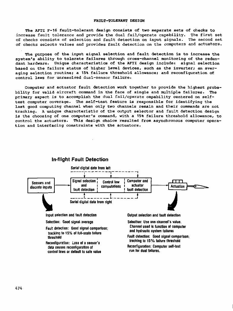
The AFT1 F-16 fault-tolerant design consists of two separate sets of checks to increase fault tolerance and provide the dual fail/operate capability. The first set of checks consists of selection and fault detection on input signals. The second set of checks selects values and provides fault detection on the computers and actuators.
The purpose of the input signal selection and fault detection is to increase the system's ability to tolerate failures through cross-channel monitoring of the redun- dant hardware. Unique characteristics of the AFT1 design include: signal selection based on the failure status of higher level devices, such as the inverter; an aver- aging selection routine; a 15% failure threshold allowance; and reconfiguration of control laws for unresolved dual-sensor failure.
Computer and actuator fault detection work together to provide the highest proba- bility for valid aircraft command in the face of single and multiple failures. The primary aspect is to accomplish the dual fail/operate capability centered on self- test computer coverage. The self-test feature is responsible for identifying the last good computing channel when only two channels remain and their commands are not tracking. A unique characteristic of the output selector and fault detection design is the choosing of one computer's command , with a 15% failure threshold allowance, to control the actuators. This design choice resulted from asynchronous computer opera- tion and interfacing constraints with the actuators.
In-flight Fault Detection
Serial digital data from lefl
Serial digital data from right
Input selection and fauft detection Output selection and fault detection
Selection: Good signal average Selection: Use one channel’s value.
Fault detection: Good signal comparison; tracking to 15% of full-scale failure threshold
Reconfiguration: Loss of a sensor’s data causes reconfiguration of control laws or default to safe value
Channel used is function of computer and hydraulic system failures
Fauft detection: Good signal comparison; tracking to 15% failure threshold
Reconfiguration: Computer self-test run for dual failures.
474

ASYNCHRONOUS COMPUTER OPERATION
Although not intended to be a primary objective of the AFT1 program, the investi- gation of the asynchronous computer operation became a major activity. The asynchro- nous architectural concept started with the intent to increase EM1 immunity and over- all system fault tolerance. It was believed that concerns about asynchronous opera- tion (testability, data congruency, and nondeterministic operation) would be allevi- ated as the design matured. Considerable engineering effort went into designing and qualifying the DFCS with much being learned about asynchronous computer operation. Despite considerable effort and improvements in the qualification process, concerns for testability remained because anomalies related to asynchronous operation occurred in flight testing. Asynchronous operation, coupled with the complexities of decoupled control and dual fail/operate capability, resulted in an increased design task, extended qualification period, and marginal testability. After envelope expan- sion, flight test evaluation of the DFCS for mission performance did not identify any new anomalies related to asynchronous operation.
Channel A
Channel B Channel C
1 Time
Concept
- Increase Immunity to EMIllightning - Increase computer channel independence - Increase fault tolerance over synchronized
system
Results
Concerns
- Random computer relationship, non. deterministic
- Incongruent data sets due to sampling skew
- Testability; assuring rellable operation for all conditions
- Deslgn task complicated by asynchronism - Qualification time extended, repeatability
poor - Complex interactions due to sampling
skews - Flight test operatlons affected due to
marginal testablllty
475

FLIGHT CONTROL 'MODE STRDCTURR
'The ART1 digital flight control.system consists of eight flight control modes, four standard and four decoupled options. The four mission-specific categories i include normal, air-to-air gunnery, air-to-surface gunnery, and air-to-surface bomb modes. Mission-specific mode selection is accomplished through a mode panel or through hands-on selectors on the throttle. Mode selection configures both flight control and avionics. Decoupled mode options. are selected through a CCV lever on the right-hand side stick controller. Decoupled o&ions include pointing, translation, and direct force in both pitch and yaw axes. The decoupled options also include enhanced maneuvering modes utilizing the pitch stick. The decoupled air-toyair gun mode provides an adaptive mode for the pitch stick, changing control structure based on pitch rate errors. This allows for control optimization of gross acquisition and fine tracking in the air-to-air mission.
In addition to the advanced decoupled modes, reconfiguration modes are included to provide dual fail/operate capability for sensor failure; however, there is a loss of decoupled and mission-specific modes. A reconfiguration mode is derived from the standard normal mode for dual failures of all primary feedback sensors, both longitu- dinal and lateral-directional. Reconfiguration modes use either synthesized sensor information or zero values as required. The digital system is backed up with an independent analog reversion mode. This provides protection for common mode errors which could cause loss of the digital system.
Controllers SP.Pitch stick SRRoll stick P.Pedals T.Throttle twist
Decoupled normal
SP-FPME SRRoll rate P.Translation T-Translation I
I I
FPME. Flight path maneuver enhancemen! t
SP.FPMOPRME
PRME- Pitch rate maneuver enhancement
Reconfiguration Standard Normal act. normal Pitch rate - SP.Normal act. AOA SR-Roll rate Roll rate P-Rud deflect Yaw rate T-None
I
t “$ ---
Landing gear
SP-Pitch iate
Takeoff and Takeoff and land land
+ t
Analog reversion mode (from any digital mode)
to-surface gun SP.Pitch rate SR-Roll rate
1
-
Decoupled air. to-surface bomb
SP.FPME SR-Roll rate P.Flat turn T-Direct lift
to-surface bomb SP.Normal act. SR-Roll rate P-Flat turn
.--- - pMZ-2
476
DECOUPLED CONTROL OPTIONS
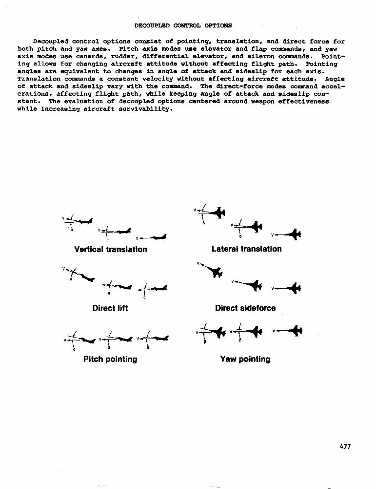
Decoupled control options consist of pointing, translation, and direct force for both pitch and yaw axes. Pitch axis modes use elevator and flap commands, and yaw axis modes use canards, rudder, differential elevator, and aileron commands. Point- ing allows for changing aircraft attitude without affecting flight path. Pointing angles are equivalent to changes in angle of attack and sideslip for each axis. Translation commands a constant velocity without affecting aircraft attitude. Angle of attack and sideslip vary with the command. The direct-force modes command accel- erations, affecting flight path, while keeping angle of attack and sideslip con- stant. The evaluation of decoupled options centered around weapon effectiveness while increasing aircraft survivability.
“+-- a “=&--d v-4 Vertical kanslation
Direct lift
-L -L 1 VT‘- VT-. VT- a 0 (I
Pitch pointing
44 t P
“+=+ “4 P Lateral translation
Direct sideforce
Yaw pointing
477

An example of the interactions which occurred between the redundancy management functions and control law is illustrated below. Triple analog input sensors are sampled asynchronously and compared within each computer. If the inputs are within an established trip level, the control laws in each computer use an average value for the triplex inputs. Because the system is asynchronous, the average value used by the control laws is slightly different in each computer. The complex control law structure, with its high gains, amplifies the difference in generating an output com- mand. The output command is monitored by each computer to assure that the differen- ces between output commands are within a given difference (that is, trip level). The amplified differences generated by the high-gain control law function cause nuisance failures in the output command monitor. If three output surface commands fail within one computer, a channel is failed. This was particularly evident in the advanced and decoupled modes during ground qualification. The control gains were reduced to pre- vent nuisance failures as a consequence of the redundancy management/control law interactions.
Pitch stick
Triplex outpd from stick
Sampled stick Input to computers
Time
Selected stick Inputs for each
Tlme
Stick output
-computer
Time
output monltor
A-B> E
B-C > L
A-C> E
Control law gain ampllflcatlon
Differences between Output monltor computer channels sees false
magnlfled failures
478
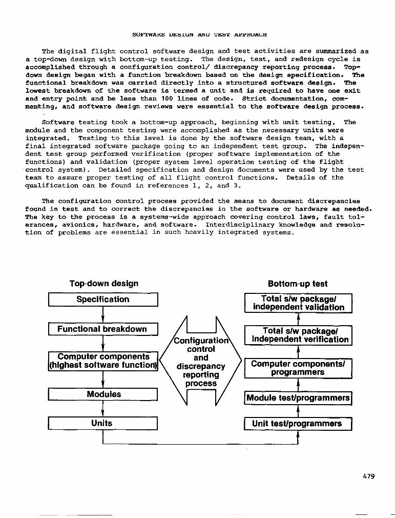
The digital flight control software design and test activities are summarized as a top-down design with bottom-up testing. The design, test, and redesign cycle is accomplished through a configuration control/ discrepancy reporting process. Top- down design began with a function breakdown based on the design specification. The functional breakdown was carried directly into a structured software design. The lowest breakdown of the software is termed a unit and is required to have one exit and entry point and be less than 100 lines of code. Strict documentation, com- menting, and software design reviews were essential to the software design process.
Software testing took a bottom-up approach, beginning with unit testing. The module and the component testing were accomplished as the necessary units were integrated. Testing to this level is done by the software design team, with a final integrated software package going to an independent test group. The indepen- dent test group performed verification (proper software implementation of the functions) and validation (proper system level operation testing of the flight control system). Detailed specification and design documents were used by the test team to assure proper testing of all flight control functions. Details of the. qualification can be found in references 1, 2, and 3.
The configuration control process provided the means to document discrepancies found in test and to correct the discrepancies in the software or hardware as needed. The key to the process is a systems-wide approach covering control laws, fault tol- erances, avionics, hardware, and software. Interdisciplinary knowledge and resolu- tion of problems are essential in such heavily integrated systems.
Top-down design
I Specification I
J Functional breakdown
J Computer components
(highest software function)
s Modules
I J
Units I
Bottom-up test
Total s/w package/ independent validation
I
1 Computer components/ 1 I programmers
4 I
1 Module test/programmers1
4 Unit test/programmers
A
479
FLIGHT TEST RESULTS: GENERAL
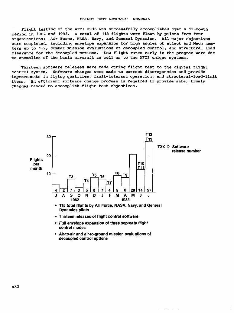
Flight testing of the AFT1 F-16 was successfully accomplished over a 13-month period in 1982 and 1983. A total of 118 flights were flown by pilots from four organizations: Air Force, NASA, Navy, and General Dynamics. All major objectives were completed, including envelope expansion for high angles of attack and Mach num- bers up to 1.2, combat mission evaluations of decoupled control, and structural load clearance for the decoupled motions. Low flight rates early in the program were due to anomalies of the basic aircraft as well as to the AFT1 unique systems.
Thirteen software releases were made during flight test to the digital flight control system. Software changes were made to correct discrepancies and provide improvements in flying qualities, fault-tolerant operation, and structural-load-limit items. An efficient software change process is required to provide safe, timely changes needed to accomplish flight test objectives.
3o r T12 T13 -
= T9
T7
7 4 9 8 20 14 JASONDJFMAMJ
27 -T
TXX I) Software release number
l 118 total fliahts by Air Force, NASA, Navy, and General Dynamics alots
l Thirteen releases of flight control software
l Full envelope expansion of three separate flight control modes
l Air-to-air and air-to-ground mission evaluations of decoupled control options
480

Built-in test (BIT) is a highly automated test sequence that assures the digital flight control system (DFCS) is free of hardware failures prior to takeoff. BIT is run prior to each flight and takes approximately 2.5 min. Two failures of the hard- ware were detected by BIT during flight testing. The first was a failure of the flap actuator, the second involved memory chips which didn't meet timing specifications at cooler temperatures. Nuisance failures of BIT occurred a number of times. The cause is believed to be EMI.
In-flight fault detection is accomplished by comparing the three values for tracking among the different channels. The only real failure was an input signal which was traced to a pushed-back pin in the aircraft wiring. The 15 false failures were due to design deficiencies rather than actual hardware failures. The design deficiencies, which resulted in both temporary (resettable) and permanent loss of flight control redundancy , were corrected in subsequent software releases.
The asynchronous computer architecture affected a wide range of developmental activities including design, software/system qualification, and flight test opera- tions. Initially DFCS qualification was not full proof because of the dependence of failure modes on computer skew. Testing at predetermined "worst case" computer skew improved testing results; however, some deficiencies still escaped detection. Ground operations during aircraft preflight were impacted by the asynchronous computer architecture. The most common problem resulted in DFCS failures, requiring reset by pilot or cycling of aircraft electrical power.
The false failures, not hardware induced, were the result of the design deficien- cies associated with asynchronous computer operation. The design deficiencies resulted from the coupling of unique computer skews with characteristics of the flight environment, such as sensor noise. Undetected during qualification, these in- flight failures resulted in envelope and flight control mode limitations until they were corrected by software changes.
The software configuration control process details the procedures equivalent to the maintenance procedures for hardware, but in the software environment. Maintain- ing safe, operational software requires specification, design, test, and documenta- tion for every change. Software change, specification, and time line for incorpora- tion directly involved flight test planning. Testing and documentation provide details for operating characteristics and/or restrictions.
The 13 flight test software releases, in which design, coding, and test of the changes were performed at General Dynamics, Fort Worth, supported the needed changes for flight test. The first four releases provided full envelope capability for the AFT1 vehicle in all flight control modes. The remaining nine releases modified the control system's control laws to improve flying qualities and the fault-detection function to improve reliability.
Software errors are software design or coding errors which escaped detection by the software verification and system validation testing. Two of the errors resulted from a loosening of the detailed established procedures. The third error was caused by a coding error involved in the correction of a previous false in-flight failure condition. The error was found when the in-flight failure condition recurred. It was found that the configuration control process provided excellent software opera- tion in the face of constant change. The testing and documentation process, when strictly followed, will detect software design and coding errors.
481

-_-- I
Flight Test Results: Fault-Tolerant Design And Software Maintainability
Fault tolerance Software maintenance
l Built-in test l Software configuration control process
- Comprehensive, automated P-min - Details configuration/operating preflight check restrictions
- Some nuisance failures due to EMI - Provides specification, design, test and
l In-flight fault detection documentation process
- Interfaces to flight test planning - Fifteen false failures detected - Three failures, cause not known l Software changes, always - One real failure detected - 129 total changes in 13 separate
l Asynchronous computer operation, problems releases
- Changes to both fault-tolerantlcontrol- - Adversely affected DFCS qualification law designs - Accomplice to in-flight failures
l Software errors occurred
- Three errors found in flight releases - Process keeps serious errors from
affecting flighj operations
482
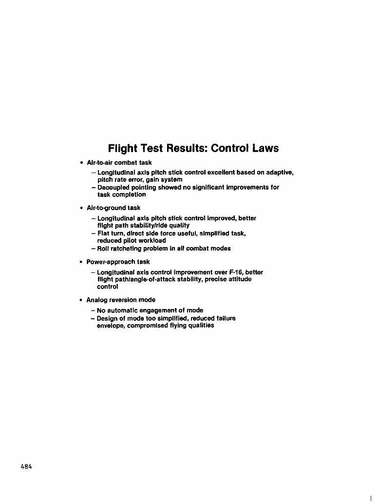
FLIGHT TEST RESULTS: CONTROL LAWS
A primary objective of the AFTI F-16 program was the evaluation of a multimode digital flight control system with decoupled aircraft control. The six different decoupled options and right-hand control options were evaluated with the decoupled feature best suited for a given task identified.
The adaptive control law, which uses pitch rate error to optimize performance in gross acquisition and fine tracking , was shown to be the best option for the air-to- air combat task. The adaptive gain control law was implemented using the right-hand controller; decoupled pointing with the pedals and twist grip showed no significant improvement for the air-to-air task.
The best feature for the air-to-ground task was again through the pitch stick with improved flight path stability and ride smoothness in turbulence. Direct side force or flat turn which is commanded through the rudder pedals improved the task by reducing pilot workload for obtaining lateral axis solutions. Problems with roll ratcheting affected all the advanced combat modes. Prefilter tuning was not suf- ficient to completely resolve the problem.
The standard normal mode, configured for gear-down, provided a greatly improved mode for power approach. Using more of a pitch-rate command system versus the nor- mal acceleration command system on the F-16's, improvements in flight path and angle- of-attack stability were made.
The need for and design of the analog reversion mode to protect against common mode failures proved most interesting. Although the analog reversion mode (ARM) was never engaged because of digital system failure, flight test experience indicates ARMS are needed. Complexity of the ARM becomes a primary issue; a simple ARM cannot provide protection at envelope extremes which are possible with the digital systems. Furthermore, the relaxed static characteristic requires a certain level of augmen- tation. The simplified reversion mode used on AFT1 provided get-home capability and level 2 flying qualities for landing as specified. However, simulation and flight test indicated a more capable ARM is needed to cover transitions from the envelope extremes possible with the digital control system (ref. 4).
483
Flight Test Results: Control Laws l Air-to-air combat task
- Longitudinal axis pitch stick control excellent based on adaptive, pitch rate error, gain system
- Decoupled pointing showed no significant improvements for task completion
l Airtoground task
- Longitudinal axis pitch stick control improved, better flight path stability/ride quality
- Flat turn, direct side force useful, simplified task, reduced pilot workioad
- Roll ratcheting problem in all combat modes
l Power-approach task
- Longitudinal axis control improvement over F-16, better flight path/angle-of-attack stability, precise attitude control
l Analog reversion mode
- No automatic engagement of mode - Design of mode too simplified, reduced failure
envelope, compromised flying qualities
484

FLIGHT TEST RESULTS: SUMMARY
Successful flight test accomplishments included envelope expansion for the pri- mary flight control modes for stability and control and for structural loads. Envelope expansion included testing for low-speed, high-angle-of-attack, and high- speed-to-Mach-l.2 conditions. Evaluation of the advanced control modes, the final goal, was accomplished in the last 15 flights.
Advanced control options were evaluated in a variety of air-to-air and air-to- surface combat tasks. Advanced flight control modes for the right-hand controller gave the best performance of the decoupled control options; flat turn showed signifi- cant improvements over conventional control methods.
The asynchronous computer architecture proved to be one of the most interesting aspects of AFTI/F-16 because of its wide-ranging effects. The fact that a given architectural design feature can affect design, qualification, and flight test is noteworthy. Flight test was culminated with no fault-tolerant-type anomalies affecting flight test operations.
Representing a state-of-the-art, flight-crucial, highly integrated control system, AFT1 provided the opportunity to find weaknesses in the developmental process resulting from the new technologies. Design and testing tools to support the devel- opment of increasing complex systems need to be developed. The goal is to develop tools which can support a generic set of digital control applications. Tools that assist in the design and testing of the fault-tolerant and software aspects of new highly integrated systems would prove beneficial.
l Successful accomplishment of flight test goals
l Advanced control options improve aircraft performance
l Asynchronous computer architecture gave difficulties, costly
l Flight-crucial controls/integrated systems stress developmental process
485
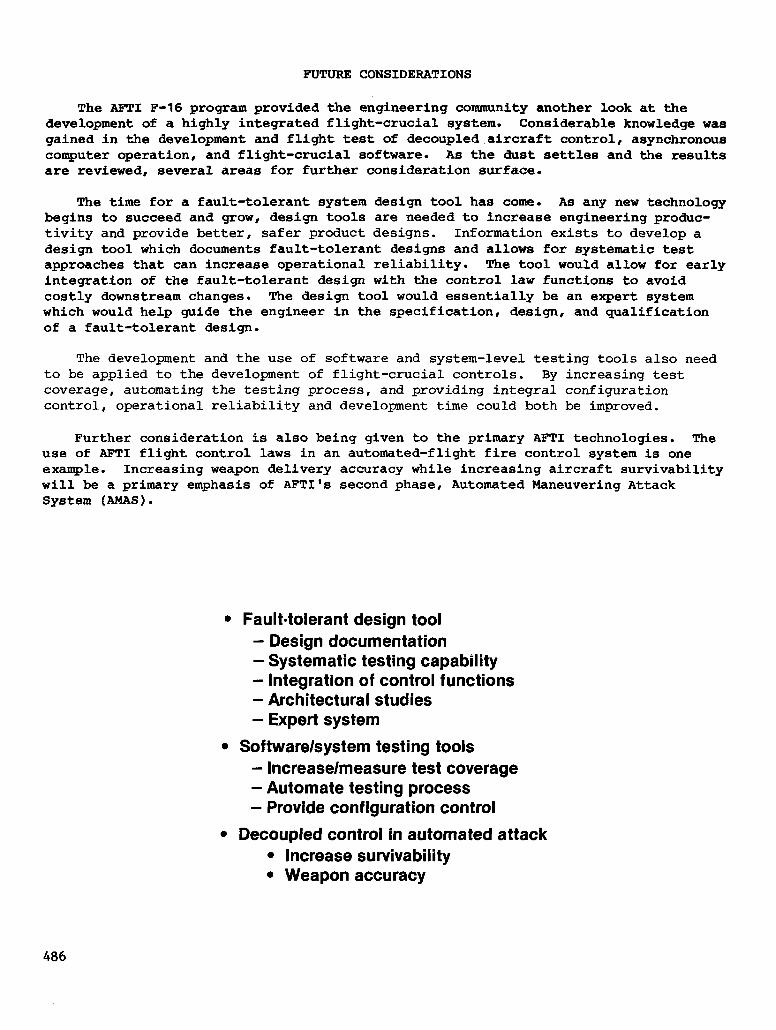
FUTURE CONSIDERATIONS
The AFT1 F-16 program provided the engineering community another look at the development of a highly integrated flight-crucial system. Considerable knowledge was gained in the development and flight test of decoupled aircraft control, asynchronous computer operation, and flight-crucial software. As the dust settles and the results are reviewed, several areas for further consideration surface.
The time for a fault-tolerant system design tool has come. As any new technology begins to succeed and grow, design tools are needed to increase engineering produc- tivity and provide better, safer product designs. Information exists to develop a design tool which documents fault-tolerant designs and allows for systematic test approaches that can increase operational reliability. The tool would allow for early integration of the fault-tolerant design with the control law functions to avoid costly downstream changes. The design tool would essentially be an expert system which would help guide the engineer in the specification, design, and qualification of a fault-tolerant design.
The development and the use of software and system-level testing tools also need to be applied to the development of flight-crucial controls. By increasing test coverage, automating the testing process, and providing integral configuration control, operational reliability and development time could both be improved.
Further consideration is also being given to the primary AFT1 technologies. The use of AFT1 flight control laws in an automated-flight fire control system is one example. Increasing weapon delivery accuracy while increasing aircraft survivability will be a primary emphasis of AFTI's second phase, Automated Maneuvering Attack System (AMAS).
l Faulttolerant design tool - Design documentation - Systematic testing capability - Integration of control functions - Architectural studies - Expert system
l Software/system testing tools - Increase/measure test coverage - Automate testing process - Provide configuration control
l Decoupled control in automated attack l Increase survivability l Weapon accuracy
486
REFERENCES
1. Mackall, D.; Ishmael, S.; and Regenie, V.: Qualification of Flight Critical AFTI/F-16 Digital Flight Control System, AIAA Paper No. 83-0060, Jan. 1983.
2. Mackall, D.; Regenie, V.; and Gordoa, M.: Qualification of the AFTI/F-16 Digital Flight Control System, Paper presented at the IEEE National Aerospace and Electronics Conference NAECON, 1983, Dayton, Ohio, May 17-19, 1983.
3. Griswold, M. R.; Gordoa, M.; and Toles, R.: AFTI/F-16 DFCS Development.Summary - A Report To Industry, Verification and Validation Testing. Proceedings of the IEEE 1983 National Aerospace and Electronics Conference NAECON 1983, vol. 2, 1983, pp. 1236-1240.
4. Ishmael, S.; Regenie, V.; and Mackall, D.: Design Implications From AFT1 F-16 Flight Test, IEEE/AIAA 5th Digital Avionics Systems Conference, Seattle, WA, Oct. 31 - Nov. 3, 1983.
487