af-600 fp tm af-600 fptm fan & pump driveapps.geindustrial.com/publibrary/checkout/det-609b...7...
TRANSCRIPT

AF-600 FPTM
Fan & Pump Drive (230V to 60HP, 460/575V to 125HP
Operating Instructions
The instructions do not purport to cover all details or variations in equipment nor to provide for every possible contingency to be met in connection with installation, operation or maintenance. Should further information be desired or should particular problems arise which are not covered su ciently for the purchaser s purposes, the matter should be referred to the GE company.
AF-600 FP is a trademark of the General Electric Company.
GE41 Woodford AvenuePlainville, CT 06062
www.geelectrical.com/drives
130R0357 *MG11Q302*
DET-609B
GE
AF-600 FPTM Fan and Pum
p Drive O
perating Instructions
DET-609B
Safety
WARNINGHIGH VOLTAGE!Frequency converters contain high voltage whenconnected to AC mains input power. Installation, start up,and maintenance should be performed by qualifiedpersonnel only. Failure to perform installation, start up, andmaintenance by qualified personnel could result in deathor serious injury.
High VoltageFrequency converts are connected to hazardous mainsvoltages. Extreme care should be taken to protect againstshock. Only trained personnel familiar with electronicequipment should install, start, or maintain this equipment.
WARNINGUNINTENDED START!When the drive is connected to AC mains, the motor maystart at any time. The drive, motor, and any drivenequipment must be in operational readiness. Failure to bein operational readiness when the drive is connected to ACmains could result in death, serious injury, equipment, orproperty damage.
Unintended StartWhen the drive is connected to the AC mains, the motormay be started by means of an external switch, a serial buscommand, an input reference signal, or a cleared faultcondition. Use appropriate cautions to guard against anunintended start.
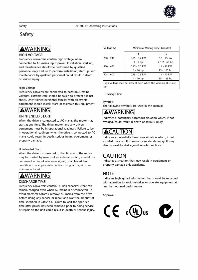
WARNINGDISCHARGE TIME!Frequency converters contain DC link capacitors that canremain charged even when AC mains is disconnected. Toavoid electrical hazards, remove AC mains from the drivebefore doing any service or repair and wait the amount oftime specified in Table 1.1. Failure to wait the specifiedtime after power has been removed prior to doing serviceor repair on the unit could result in death or serious injury.
Voltage (V) Minimum Waiting Time (Minutes)
4 15
200 - 240 0.75 - 3.7 kW1 - 5 hp
5.5 - 45 kW7 1/2 - 60 hp
380 - 480 0.75 - 7.5 kW1 - 10 hp
11 - 90 kW15 - 125 hp
525 - 600 0.75 - 7.5 kW1 - 10 hp
11 - 90 kW15 - 125 hp
High voltage may be present even when the warning LEDs are
off!
Discharge Time
SymbolsThe following symbols are used in this manual.
WARNINGIndicates a potentially hazardous situation which, if notavoided, could result in death or serious injury.
CAUTIONIndicates a potentially hazardous situation which, if notavoided, may result in minor or moderate injury. It mayalso be used to alert against unsafe practices.
CAUTIONIndicates a situation that may result in equipment orproperty-damage-only accidents.
NOTEIndicates highlighted information that should be regardedwith attention to avoid mistakes or operate equipment atless than optimal performance.
Approvals
Safety AF-600 FP Operating Instructions

Safety AF-600 FP Operating Instructions

Contents
1 Introduction 4
1.1 Purpose of the Manual 6
1.2 Additional Resources 6
1.3 Product Overview 6
1.4 Internal Drive Controller Functions 6
1.5 Unit Sizes and Power Ratings 7
2 Installation 8
2.1 Installation Site Check List 8
2.2 Drive and Motor Pre-installation Check List 8
2.3 Mechanical Installation 8
2.3.1 Cooling 8
2.3.2 Lifting 9
2.3.3 Mounting 9
2.3.4 Tightening Torques 9
2.4 Electrical Installation 10
2.4.1 Requirements 11
2.4.2 Earth (Grounding) Requirements 12
2.4.2.1 Leakage Current (>3,5mA) 12
2.4.2.2 Grounding Using Shielded Cable 13
2.4.2.3 Grounding Using Conduit 13
2.4.3 Motor Connection 13
2.4.4 AC Mains Connection 14
2.4.5 Control Wiring 15
2.4.5.1 Access 15
2.4.5.2 Control Terminal Types 15
2.4.5.3 Wiring to Control Terminals 16
2.4.5.4 Using Screened Control Cables 17
2.4.5.5 Control Terminal Functions 17
2.4.5.6 Terminal 53 and 54 Switches 17
2.4.6 Serial Communication 18
3 Start Up and Functional Testing 19
3.1 Pre-start 19
3.1.1 Safety Inspection 19
3.1.2 Start Up Check List 20
3.2 Applying Power to the Drive 21
3.3 Basic Operational Programming 21
3.4 Auto Tune 21
3.5 Check Motor Rotation 22
Contents AF-600 FP Operating Instructions
1

3.6 Local-control Test 22
3.7 System Start Up 23
4 User Interface 24
4.1 Keypad 24
4.1.1 Keypad Layout 24
4.1.2 Setting Keypad Display Values 25
4.1.3 Display Menu Keys 25
4.1.4 Navigation Keys 26
4.1.5 Operation Keys 26
4.2 Back Up and Copying Parameter Settings 26
4.2.1 Uploading Data to the keypad 27
4.2.2 Downloading Data from the keypad 27
4.3 Restoring Default Settings 27
4.3.1 Recommended Initialisation 27
4.3.2 Manual Initialisation 27
5 About Drive Programming 28
5.1 Introduction 28
5.2 Programming Example 28
5.3 Control Terminal Programming Examples 30
5.4 International/North American Default Parameter Settings 31
5.5 Parameter Menu Structure 32
5.5.1 Quick Menu Structure 32
5.5.2 Main Menu Structure 33
5.6 Remote Programming with DCT-10 40
6 Application Set-Up Examples 41
6.1 Introduction 41
6.2 Application Examples 41
7 Status Messages 46
7.1 Status Display 46
7.2 Status Message Definitions Table 46
8 Warnings and Alarms 49
8.1 System Monitoring 49
8.2 Warning and Alarm Types 49
8.3 Warning and Alarm Displays 49
8.4 Warning and Alarm Definitions 50
8.4.1 Fault Messages 51
9 Basic Troubleshooting 57
Contents AF-600 FP Operating Instructions
2

9.1 Start Up and Operation 57
10 Specifications 59
10.1 Power-dependent Specifications 59
10.2 General Technical Data 66
10.3 Fuse Tables 71
10.3.1 Recommendations 71
10.3.2 CE Compliance 72
10.3.3 NEC and UL Compliance 77
10.3.4 Substitute Fuses for 240 V 83
10.4 Connection Tightening Torques 83
Index 84
Contents AF-600 FP Operating Instructions
3

1 Introduction
Illustration 1.1 Exploded View Unit Size 1X
1 Keypad 10 Motor output terminals 96 (U), 97 (V), 98 (W)
2 RS-485 serial bus connector (+68, -69) 11 Relay 1 (01, 02, 03)
3 Analog I/O connector 12 Relay 2 (04, 05, 06)
4 Keypad input plug 13 Brake (-81, +82) and load sharing (-88, +89) terminals
5 Analog switches (A53), (A54) 14 Mains input terminals 91 (L1), 92 (L2), 93 (L3)
6 Cable strain relief / PE ground 15 USB connector
7 Decoupling plate 16 Serial bus terminal switch
8 Grounding clamp (PE) 17 Digital I/O and 24 V power supply
9 Shielded cable grounding clamp and strain relief 18 Control cable cover plate
Introduction AF-600 FP Operating Instructions
4
11

Illustration 1.2 Exploded View Unit Sizes 21, 22, 31, and 32
1 Keypad 11 Relay 2 (04, 05, 06)
2 Cover 12 Lifting ring
3 RS-485 serial bus connector 13 Mounting slot
4 Digital I/O and 24 V power supply 14 Grounding clamp (PE)
5 Analog I/O connector 15 Cable strain relief / PE ground
6 Cable strain relief / PE ground 16 Brake terminal (-81, +82)
7 USB connector 17 Load sharing terminal (DC bus) (-88, +89)
8 Serial bus terminal switch 18 Motor output terminals 96 (U), 97 (V), 98 (W)
9 Analog switches (A53), (A54) 19 Mains input terminals 91 (L1), 92 (L2), 93 (L3)
10 Relay 1 (01, 02, 03)
Introduction AF-600 FP Operating Instructions
5
1 1

1.1 Purpose of the Manual
This manual is intended to provide detailed information forthe installation and start up of the frequency converter.Chapter 2 Installation provides requirements formechanical and electrical installation, including input,motor, control and serial communications wiring, andcontrol terminal functions. Chapter 3 Start Up andFunctional Testing provides detailed procedures for startup, basic operational programming, and functional testing.The remaining chapters provide supplementary details.These include user interface, detailed programming,application examples, start-up troubleshooting, and specifi-cations.
1.2 Additional Resources
Other resources are available to understand advanceddrive functions and programming.
• The Programming Guide provides greater detailin how to work with parameters and manyapplication examples.
• The Design Guide is intended to provide detailedcapabilities and functionality to design motorcontrol systems.
• Optional equipment is available that may changesome of the procedures described. Be sure to seethe instructions supplied with those options forspecific requirements.
1.3 Product Overview
A drive is an electronic motor controller that converts ACmains input into a variable AC waveform output. Thefrequency and voltage of the output are regulated tocontrol the motor speed or torque. The drive can vary thespeed of the motor in response to system feedback, suchas changing temperature or pressure for controlling fan,compressor, or pump motors. The drive can also regulatethe motor by responding to remote commands fromexternal controllers.
In addition, the drive monitors the system and motorstatus, issues warnings or alarms for fault conditions, startsand stops the motor, optimizes energy efficiency, andoffers many more control, monitoring, and efficiencyfunctions. Operation and monitoring functions areavailable as status indications to an outside control systemor serial communication network.
1.4 Internal Drive Controller Functions
Below is a block diagram of the frequency converter'sinternal components. See Table 1.1 for their functions.
Illustration 1.3 Drive Block Diagram
Area Title Functions
1 Mains input • Three-phase AC mains powersupply to the drive
2 Rectifier • The rectifier bridge convertsthe AC input to DC current tosupply inverter power
3 DC bus • The frequency converter'sintermediate DC-bus circuithandles the DC current
4 DC reactors • Filter the intermediate DCcircuit voltage
• Prove line transient protection
• Reduce RMS current
• Raise the power factorreflected back to the line
• Reduce harmonics on the ACinput
5 Capacitor bank • Stores the DC power
• Provides ride-throughprotection for short powerlosses
6 Inverter • Converts the DC into acontrolled PWM AC waveformfor a controlled variableoutput to the motor
7 Output to motor • Regulated three-phase output
power to the motor
8 Control circuitry • Input power, internalprocessing, output, and motorcurrent are monitored toprovide efficient operationand control
• User interface and externalcommands are monitored and
performed
• Status output and control canbe provided
Table 1.1 Drive Internal Components
Introduction AF-600 FP Operating Instructions
6
11

1.5 Unit Sizes and Power Ratings
References to unit sizes used in this manual are defined in Table 1.2.
Unit sizes
IP20 / Open Chassis IP55 / Nema 12
Volts 12 13 23 24 33 34 15 21 22 31 32
200-240 1-3 HP 5 HP 7.5-15 HP 20-25 HP 30-40 HP 50-60 HP 1-5 HP 7.5-15 HP 20 HP 25-40 HP 50-60 HP
380-480 1-5 HP 7.5-10 HP 15-25 HP 25-40 HP 50-75 HP100-125
HP 1-10 HP 15-25 HP 25-40 HP 50-75 HP100-125
HP
525-600 - 1-10 HP 15-25 HP 25-40 HP 50-75 HP100-125
HP 1-10 HP 15-25 HP 25-40 HP 50-75 HP100-125
HP
Introduction AF-600 FP Operating Instructions
7
1 1

2 Installation
2.1 Installation Site Check List
• The drive relies on the ambient air for cooling.Observe the limitations on ambient airtemperature for optimal operation
• Ensure that the installation location has sufficientsupport strength to mount the drive
• Keep the drive interior free from dust and dirt.Ensure that the components stay as clean aspossible. In construction areas, provide aprotective covering. Optional IP55 (NEMA 12)enclosures may be necessary.
• Keep the manual, drawings, and diagramsaccessible for detailed installation and operationinstructions. It is important that the manual isavailable for equipment operators.
• Locate equipment as near to the motor aspossible. Keep motor cables as short as possible.Check the motor characteristics for actualtolerances. Do not exceed
• 300m (1000ft) for unshielded motorleads
• 150m (500ft) for shielded cable.
2.2 Drive and Motor Pre-installation CheckList
• Compare the model number of unit on thenameplate to what was ordered to verify theproper equipment
• Ensure each of the following are rated for samevoltage:
Mains (power)
Drive
Motor
• Ensure that drive output current rating is equal toor greater than motor full load current for peakmotor performance
Motor size and drive power must matchfor proper overload protection
If drive rating is less than motor, fullmotor output cannot be achieved
2.3 Mechanical Installation
2.3.1 Cooling
• To provide cooling airflow, mount the unit to asolid flat surface or to the optional back plate(see 2.3.3 Mounting)
• Top and bottom clearance for air cooling must beprovided. Generally, 100-225mm (4-10in) isrequired. See Illustration 2.1 for clearancerequirements
• Improper mounting can result in over heatingand reduced performance
• Derating for temperatures starting between 40°C(104°F) and 50°C (122°F) and elevation 1000m(3300ft) above sea level must be considered. Seethe equipment Design Guide for detailedinformation.
Illustration 2.1 Top and Bottom Cooling Clearance
Size 12 13 - 15 21 22
a/b (mm) 100 100 - 100 200 200
a/b (in) 4 4 - 4 8 8
Size 23 24 31 32 33 34
a/b (mm) 200 200 200 225 200 225
a/b (in) 8 8 8 9 8 9
Table 2.1 Minimum Airflow Clearance Requirements
Installation AF-600 FP Operating Instructions
8
22

2.3.2 Lifting
• Check the weight of the unit to determine a safelifting method
• Ensure that the lifting device is suitable for thetask
• If necessary, plan for a hoist, crane, or forklift withthe appropriate rating to move the unit
• For lifting, use hoist rings on the unit, whenprovided
2.3.3 Mounting
• Mount the unit vertically
• The drive allows side by side installation
• Ensure that the strength of the mounting locationwill support the unit weight
• Mount the unit to a solid flat surface or to theoptional back plate to provide cooling airflow(see Illustration 2.2 and Illustration 2.3)
• Improper mounting can result in over heatingand reduced performance
• Use the slotted mounting holes on the unit forwall mounting, when provided
Illustration 2.2 Proper Mounting with Back Plate
Item A is a back plate properly installed for requiredairflow to cool the unit.
Illustration 2.3 Proper Mounting with Railings
NOTEBack plate is needed when mounted on railings.
2.3.4 Tightening Torques
See 10.4 Connection Tightening Torques for propertightening specifications.
Installation AF-600 FP Operating Instructions
9
2 2

2.4 Electrical Installation
This section contains detailed instructions for wiring the drive. The following tasks are described.
• Wiring the motor to the drive output terminals
• Wiring the AC mains to the drive input terminals
• Connecting control and serial communication wiring
• After power has been applied, checking input and motor power; programming control terminals for their intendedfunctions
Illustration 2.4 shows a basic electrical connection.
Illustration 2.4 Basic Wiring Schematic Drawing.
Installation AF-600 FP Operating Instructions
10
22

2.4.1 Requirements
WARNINGEQUIPMENT HAZARD!Rotating shafts and electrical equipment can be hazardous.All electrical work must conform to national and localelectrical codes. It is strongly recommended that instal-lation, start up, and maintenance be performed only bytrained and qualified personnel. Failure to follow theseguidelines could result in death or serious injury.
CAUTIONWIRING ISOLATION!Run input power, motor wiring and control wiring in threeseparate metallic conduits or use separated shielded cablefor high frequency noise isolation. Failure to isolate power,motor and control wiring could result in less thanoptimum drive and associated equipment performance.
For your safety, comply with the following requirements.
• Electronic controls equipment is connected tohazardous mains voltage. Extreme care should betaken to protect against electrical hazards whenapplying power to the unit.
• Run motor cables from multiple frequencyconverters separately. Induced voltage fromoutput motor cables run together can chargeequipment capacitors even with the equipmentturned off and locked out.
Overload and Equipment Protection
• An electronically activated function within thedrive provides overload protection for the motor.The overload calculates the level of increase toactivate timing for the trip (controller outputstop) function. The higher the current draw, thequicker the trip response. The overload providesClass 20 motor protection. See 8 Warnings andAlarms for details on the trip function.
• Because the motor wiring carries high frequencycurrent, it is important that wiring for mains,motor power, and control are run separately. Usemetallic conduit or separated shielded wire.Failure to isolate power, motor, and controlwiring could result in less than optimumequipment performance. See Illustration 2.5.
Illustration 2.5 Proper Electrical Installation Using Conduit
• All frequency converters must be provided withshort-circuit and over-current protection. Inputfusing is required to provide this protection, seeIllustration 2.6. See maximum fuse ratings in 10.3 Fuse Tables.
Illustration 2.6 Drive Fuses
Wire Type and Ratings
• All wiring must comply with local and nationalregulations regarding cross-section and ambienttemperature requirements.
• GE recommends that all power connections bemade with a minimum 75° C rated copper wire.
• See 10.1 Power-dependent Specifications forrecommended wire sizes.
Installation AF-600 FP Operating Instructions
11
2 2

2.4.2 Earth (Grounding) Requirements
WARNINGGROUNDING HAZARD!For operator safety, it is important to ground driveproperly in accordance with national and local electricalcodes as well as instructions contained within theseinstructions. Ground currents are higher than 3,5mA.Failure to ground drive properly could result in death orserious injury.
NOTEIt is the responsibility of the user or certified electricalinstaller to ensure correct grounding (earthing) of theequipment in accordance with national and local electricalcodes and standards.
• Follow all local and national electrical codes toground electrical equipment properly
• Proper protective grounding for equipment withground currents higher than 3,5mA must beestablished, see Leakage Current (>3,5mA)
• A dedicatedground wire is required for inputpower, motor power and control wiring
• Use the clamps provided with on the equipmentfor proper ground connections
• Do not ground one drive to another in a “daisychain” fashion
• Keep the ground wire connections as short aspossible
• Use of high-strand wire to reduce electrical noiseis recommended
• Follow motor manufacturer wiring requirements
2.4.2.1 Leakage Current (>3,5mA)
Follow national and local codes regarding protectiveearthing of equipment with a leakage current > 3,5mA.Drive technology implies high frequency switching at highpower. This will generate a leakage current in the earthconnection. A fault current in the drive at the outputpower terminals might contain a DC component which cancharge the filter capacitors and cause a transient earthcurrent. The earth leakage current depends on varioussystem configurations including RFI filtering, screenedmotor cables, and drive power.
EN/IEC61800-5-1 (Power Drive System Product Standard)requires special care if the leakage current exceeds 3,5mA.Earth grounding must be reinforced in one of thefollowing ways:
• Earth ground wire of at least 10mm2
• Two separate earth ground wires both complyingwith the dimensioning rules
See EN 60364-5-54 § 543.7 for further information.
Using RCDsWhere residual current devices (RCDs), also known as earthleakage circuit breakers (ELCBs), are used, comply with thefollowing:
Use RCDs of type B only which are capable ofdetecting AC and DC currents
Use RCDs with an inrush delay to prevent faultsdue to transient earth currents
Dimension RCDs according to the system configu-ration and environmental considerations
Installation AF-600 FP Operating Instructions
12
22

2.4.2.2 Grounding Using Shielded Cable
Earthing (grounding) clamps are provided for motor wiring(see Illustration 2.7).
Illustration 2.7 Grounding with Shielded Cable
2.4.2.3 Grounding Using Conduit
CAUTIONGROUNDING HAZARD!Do not use conduit connected to the drive as areplacement for proper grounding. Ground currents arehigher than 3.5mA. Improper grounding can result inpersonal injury or electrical shorts.
Dedicated grounding clamps are provided (SeeIllustration 2.8).
Illustration 2.8 Grounding with Conduit
1. Use a wire stripper to remove the insulation forproper grounding.
2. Secure the grounding clamp to the strippedportion of the wire with the screws provided.
3. Secure the grounding wire to the groundingclamp provided.
2.4.3 Motor Connection
WARNINGINDUCED VOLTAGE!Run output motor cables from multiple frequencyconverters separately. Induced voltage from output motorcables run together can charge equipment capacitors evenwith the equipment turned off and locked out. Failure torun output motor cables separately could result in deathor serious injury.
• For maximum wire sizes see 10.1 Power-dependentSpecifications
• Comply with local and national electrical codesfor cable sizes
• Motor wiring knockouts or access panels areprovided at the base of IP55 / Nema 12 units
• Do not install power factor correction capacitorsbetween the drive and the motor
• Do not wire a starting or pole-changing devicebetween the drive and the motor
• Connect the 3-phase motor wiring to terminals96 (U), 97 (V), and 98 (W)
• Ground the cable in accordance with groundinginstructions provided
• Torque terminals in accordance with theinformation provided in 10.4.1 ConnectionTightening Torques
• Follow motor manufacturer wiring requirements
The three following illustrations represent mains input,motor, and earth grounding for basic frequency converters.Actual configurations vary with unit types and optionalequipment.
Installation AF-600 FP Operating Instructions
13
2 2

Illustration 2.9 Motor, Mains and Earth Wiring for Frame Sizes 1X
Illustration 2.10 Motor, Mains and Earth Wiring for Frame Sizes
2X and Above Using Shielded Cable
Illustration 2.11 Motor, Mains and Earth Wiring for Frame Sizes
2X and Above Using Conduit
2.4.4 AC Mains Connection
• Size wiring based upon the input current of thedrive. For maximum wire sizes see 10.1 Power-dependent Specifications.
• Comply with local and national electrical codesfor cable sizes.
• Connect 3-phase AC input power wiring toterminals L1, L2, and L3 (see Illustration 2.12).
• Input power will be connected to the mains inputterminals.
Illustration 2.12 Connecting to AC Mains
Installation AF-600 FP Operating Instructions
14
22

• Ground the cable in accordance with groundinginstructions provided in 2.4.2 Earth (Grounding)Requirements
• All frequency converters may be used with anisolated input source as well as with groundreference power lines. When supplied from anisolated mains source (IT mains or floating delta)or TT/TN-S mains with a grounded leg (groundeddelta), set SP-50 RFI Filter to OFF. When off, theinternal RFI filter capacitors between the chassisand the intermediate circuit are isolated to avoiddamage to the intermediate circuit and to reduceearth capacity currents in accordance with IEC61800-3.
2.4.5 Control Wiring
• Isolate control wiring from high powercomponents in the drive.
• If the drive is connected to a thermistor, for PELVisolation, optional thermistor control wiring mustbe reinforced/double insulated. A 24 VDC supplyvoltage is recommended.
2.4.5.1 Access
• Remove access cover plate with a screw driver.See Illustration 2.13.
• Or remove front cover by loosening attachingscrews. See Illustration 2.14.Tightening torque for front cover is 2.0Nm forunit size 15 and 2.2Nm for unit sizes 2X and 3X.
130BT248
Illustration 2.13 Control Wiring Access for IP20 / Open chassisenclosures
130BT334.11
Illustration 2.14 Control Wiring Access for IP55 / Nema 12enclosures
2.4.5.2 Control Terminal Types
Illustration 2.18 shows the removable drive connectors.Terminal functions and default settings are summarized inTable 2.2.
Illustration 2.15 Control Terminal Locations
• Connector 1 provides four programmable digitalinputs terminals, two additional digital terminalsprogrammable as either input or output, a 24VDC terminal supply voltage, and a common foroptional customer supplied 24V DC voltage
• Connector 2 terminals (+)68 and (-)69 are for anRS-485 serial communications connection
• Connector 3 provides two analog inputs, oneanalog output, 10V DC supply voltage, andcommons for the inputs and output
Installation AF-600 FP Operating Instructions
15
2 2

• Connector 4 is a USB port available for use withthe DCT-10
• Also provided are two Form C relay outputs thatare in various locations depending upon the driveconfiguration and size
• Some options available for ordering with the unitmay provide additional terminals. See the manualprovided with the equipment option.
See 10.2 General Technical Data for terminal ratings details.
Terminal DescriptionDigital Inputs/Outputs
Terminal ParameterDefaultSetting Description
12, 13 - +24V DC 24V DC supply
voltage. Maximumoutput current is200mA total for all
24V loads. Useable fordigital inputs andexternal transducers.
18 E-01 [8] Start
Digital inputs.
19 E-02 [0] Nooperation
32 E-05 [0] Nooperation
33 E-06 [0] Nooperation
27 E-03 [0] No
operation
Selectable for either
digital input oroutput. Default settingis input.
29 E-04 [14] JOG
20 - Common for digitalinputs and 0Vpotential for 24Vsupply.
Analog Inputs/Outputs
39 -
Common for analogoutput
42 AN-50 Speed 0 -
High Limit
Programmable analog
output. The analogsignal is 0-20mA or4-20mA at a
maximum of 500Ω50 - +10V DC 10V DC analog supply
voltage. 15mAmaximum commonlyused for potenti-ometer or thermistor.
53 AN-1# Reference Analog input.
Selectable for voltageor current. SwitchesA53 and A54 select
mA or V.
54 AN-2# Feedback
Terminal DescriptionDigital Inputs/Outputs
Terminal ParameterDefaultSetting Description
55 -
Common for analoginput
Serial Communication
61 -
Integrated RC-Filter forcable screen. ONLY forconnecting the screenwhen experiencingEMC problems.
68 (+) O-3# RS-485 Interface. Acontrol card switch isprovided fortermination resistance.
69 (-) O-3#
Relays
01, 02, 03 E-24 [0] [0] Alarm Form C relay output.
Usable for AC or DCvoltage and resistiveor inductive loads.
04, 05, 06 E-24 [1] [0] Running
Table 2.2 Terminal Description
2.4.5.3 Wiring to Control Terminals
Control terminal connectors can be unplugged from thedrive for ease of installation, as shown in Illustration 2.16.
Illustration 2.16 Unplugging Control Terminals
1. Open the contact by inserting a small screwdriverinto the slot above or below the contact, asshown in Illustration 2.17.
2. Insert the bared control wire into the contact.
3. Remove the screwdriver to fasten the control wireinto the contact.
4. Ensure the contact is firmly established and notloose. Loose control wiring can be the source ofequipment faults or less than optimal operation.
Installation AF-600 FP Operating Instructions
16
22

See 10.1 Power-dependent Specifications for control terminalwiring sizes.
See 6 Application Set-Up Examples for typical control wiringconnections.
Illustration 2.17 Connecting Control Wiring
2.4.5.4 Using Screened Control Cables
Correct screeningThe preferred method in most cases is to secure controland serial communication cables with screening clampsprovided at both ends to ensure best possible highfrequency cable contact.
50/60Hz ground loopsWith very long control cables, ground loops may occur. Toeliminate ground loops, connect one end of the screen-to-ground with a 100nF capacitor (keeping leads short).
Avoid EMC noise on serial communicationTo eliminate low-frequency noise between frequencyconverters, connect one end of the screen to terminal 61.This terminal is connected to ground via an internal RClink. Use twisted-pair cables to reduce interferencebetween conductors.
2.4.5.5 Control Terminal Functions
Drive functions are commanded by receiving control inputsignals.
• Each terminal must be programmed for thefunction it will be supporting in the parametersassociated with that terminal. SeeTable 2.2 forterminals and associated parameters.
• It is important to confirm that the controlterminal is programmed for the correct function.See 4 User Interface for details on accessingparameters and for details on programming.
• The default terminal programming is intended toinitiate drive functioning in a typical operationalmode.
2.4.5.6 Terminal 53 and 54 Switches
• Analog input terminals 53 and 54 can selecteither voltage (0 to 10V) or current (0/4-20mA)input signals
• Remove power to the drive before changingswitch positions
• Set switches A53 and A54 to select the signaltype. U selects voltage, I selects current.
• The switches are accessible when the keypad hasbeen removed (see Illustration 2.18). Note thatsome option cards available for the unit maycover these switches and must be removed tochange switch settings. Always remove power tothe unit before removing option cards.
• Terminal 53 default is for a speed reference signalin open loop set in DR-61 Terminal 53 SwitchSetting
• Terminal 54 default is for a feedback signal inclosed loop set in DR-63 Terminal 54 SwitchSetting
Installation AF-600 FP Operating Instructions
17
2 2

130BT310.10
Illustration 2.18 Location of Terminals 53 and 54 Switches
2.4.6 Serial Communication
Connect RS-485 serial communication wiring to terminals(+)68 and (-)69.
• Screened serial communication cable isrecommended
• See 2.4.2 Earth (Grounding) Requirements forproper grounding
Illustration 2.19 Serial Communication Wiring Diagram
For basic serial communication set-up, select the following
1. Protocol type in O-30 Protocol.
2. Drive address in O-31 Address.
3. Baud rate in O-32 Drive Port Baud Rate.
• Four communication protocols are internal to thedrive. Follow motor manufacturer wiringrequirements.
Drive profile
Modbus RTU
Metasys N2®
Apogee FLN®
• Functions can be programmed remotely usingthe protocol software and RS-485 connection orin parameter group O-## Options / Comms
• Selecting a specific communication protocolchanges various default parameter settings tomatch that protocol’s specifications along withmaking additional protocol-specific parametersavailable
• Option cards which install into the drive areavailable to provide additional communicationprotocols. See the option-card documentation forinstallation and operation instructions
Installation AF-600 FP Operating Instructions
18
22

3 Start Up and Functional Testing
3.1 Pre-start
3.1.1 Safety Inspection
WARNINGHIGH VOLTAGE!If input and output connections have been connectedimproperly, there is potential for high voltage on theseterminals. If power leads for multiple motors areimproperly run in same conduit, there is potential forleakage current to charge capacitors within the drive, evenwhen disconnected from mains input. For initial start up,make no assumptions about power components. Followpre-start procedures. Failure to follow pre-start procedurescould result in personal injury or damage to equipment.
1. Input power to the unit must be OFF and lockedout. Do not rely on the drive disconnect switchesfor input power isolation.
2. Verify that there is no voltage on input terminalsL1 (91), L2 (92), and L3 (93), phase-to-phase andphase-to-ground,
3. Verify that there is no voltage on outputterminals 96 (U), 97 (V), and 98 (W), phase-to-phase and phase-to-ground.
4. Confirm continuity of the motor by measuringohm values on U-V (96-97), V-W (97-98), and W-U(98-96).
5. Check for proper grounding of the drive as wellas the motor.
6. Inspect the drive for loose connections onterminals.
7. Record the following motor-nameplate data:power, voltage, frequency, full load current, andnominal speed. These values are needed toprogram motor nameplate data later.
8. Confirm that the supply voltage matches voltageof drive and motor.
Start Up and Functional Tes... AF-600 FP Operating Instructions
19
3 3

3.1.2 Start Up Check List
CAUTIONBefore applying power to the unit, inspect the entire installation as detailed in Table 3.1. Check mark those items whencompleted.
Inspect for Description Auxiliary equipment • Look for auxiliary equipment, switches, disconnects, or input fuses/circuit
breakers that may reside on input power side of drive or output side to motor.Examine their operational readiness and ensure that they are ready in allrespects for operation at full speed.
• Check function and installation of any sensors used for feedback to drive
• Remove power factor correction caps on motor(s), if present
Cable routing • Ensure that input power, motor wiring, and control wiring are separated or inthree separate metallic conduits for high frequency noise isolation
Control wiring • Check for broken or damaged wires and loose connections
• Check that control wiring is isolated from power and motor wiring for noiseimmunity
• Check the voltage source of the signals, if necessary
• The use of shielded cable or twisted pair is recommended. Ensure that theshield is terminated correctly.
Cooling clearance • Measure that top and bottom clearance is adequate to ensure proper air flowfor cooling
EMC considerations • Check for proper installation regarding electromagnetic compatibility
Environmental considerations • See equipment label for the maximum ambient operating temperature limits
• Humidity levels must be 5-95% non-condensing
Fusing and circuit breakers • Check for proper fusing or circuit breakers
• Check that all fuses are inserted firmly and in operational condition and that allcircuit breakers are in the open position
Grounding • The unit requires a ground wire from its chassis to the building ground
• Check for good ground connections that are tight and free of oxidation
• Grounding to conduit or mounting the back panel to a metal surface is not asuitable ground
Input and output power wiring • Check for loose connections
• Check that motor and mains are in separate conduit or separated screenedcables
Panel interior • Inspect that the unit interior is free of dirt, metal chips, moisture, and corrosion
Switches • Ensure that all switch and disconnect settings are in the proper position
Vibration • Check that the unit is mounted solidly or that shock mounts are used, asnecessary
• Look for any unusual amount of vibration the unit may be subjected to
Table 3.1 Start Up Check List
Start Up and Functional Tes... AF-600 FP Operating Instructions
20
33

3.2 Applying Power to the Drive
WARNINGHIGH VOLTAGE!Frequency converters contain high voltage whenconnected to AC mains. Installation, start-up andmaintenance should be performed by qualified personnelonly. Failure to perform installation, start-up andmaintenance by qualified personnel could result in deathor serious injury.
WARNINGUNINTENDED START!When drive is connected to AC mains, the motor may startat any time. The drive, motor, and any driven equipmentmust be in operational readiness. Failure to be inoperational readiness when the drive is connected to ACmains could result in death, serious injury, equipment, orproperty damage.
1. Confirm input voltage is balanced within 3%. Ifnot, correct input voltage imbalance beforeproceeding. Repeat procedure after voltagecorrection.
2. Ensure optional equipment wiring, if present,matches installation application.
3. Ensure that all operator devices are in the OFFposition. Panel doors closed or cover mounted.
4. Apply power to the unit. DO NOT start the driveat this time. For units with a disconnect switch,turn to the ON position to apply power to thedrive.
3.3 Basic Operational Programming
Drives require basic operational programming prior torunning for best performance. Basic operationalprogramming requires entering motor-nameplate data forthe motor being operated and the minimum andmaximum motor speeds. Enter data in accordance with thefollowing procedure. Parameter settings recommended areintended for start up and checkout purposes. Applicationsettings may vary. See 4 User Interface for detailedinstructions on entering data through the keypad.
Enter data with power ON, but prior to operating thedrive.
1. Press [Quick Menu] on the keypad.
3. Use the navigation keys to scroll to Quick Startand press [OK].
4. Select language and press [OK]. Then enter themotor data in parameters P-02, P-03, P-06, P-07,F-04 and F-05. The information can be found onthe motor nameplate. The entire quick menu isshown in 5.5.1 Quick Menu Structure
P-07 Motor Power [kW] or P-02 MotorPower [HP]
F-05 Motor Rated Voltage
F-04 Base Frequency
P-03 Motor Current
P-06 Base Speed
5. F-07 Accel Time 1 is recommended as 60 secondsfor fans or 10 seconds for pumps.
6. F-08 Decel Time 1 is recommended as 60 secondsfor fans or 10 seconds for pumps.
7. For F-10 enter Elec OL Trip 1 for Class 20overload protection. For further information,please see 2.4.1 Requirements
8. For F-16 Motor Speed Low Limit [Hz] enter theapplication requirements. If these values areunknown at this time, the following values arerecommended. These values will ensure initialdrive operation. However, take any precautionsnecessary to prevent equipment damage. Makesure that the recommended values are safe touse for functional testing before starting theequipment.
Fan = 20Hz
Pump = 20Hz
Compressor = 30Hz
9. In F-15 Motor Speed High Limit [Hz] enter themotor frequency from F-04 Base Frequency.
This concludes the quick set-up procedure. Press [Status]to return to the operational display.
In P-04 Auto Tune select Reduced Auto Tune or Full AutoTune and follow on-screen instructions. See 3.4 Auto Tune
3.4 Auto Tune
Auto tune is a test procedure that measures the electricalcharacteristics of the motor to optimize compatibilitybetween the drive and the motor.
• The drive builds a mathematical model of themotor for regulating output motor current. Theprocedure also tests the input phase balance ofelectrical power. It compares the motor character-
Start Up and Functional Tes... AF-600 FP Operating Instructions
21
3 3

istics with the data entered in P-02, P-03, P-06,P-07, F-04 and F-05.
• It does not cause the motor to run or harm tothe motor
• Some motors may be unable to run the completeversion of the test. In that case, select ReducedAuto Tune
• If an output filter is connected to the motor,select Reduced Auto Tune
• If warnings or alarms occur, see 8 Warnings andAlarms
• Run this procedure on a cold motor for bestresults
3.5 Check Motor Rotation
Prior to running the drive, check the motor rotation. Themotor will run briefly at 5Hz or the minimum frequency setin F-16 Motor Speed Low Limit [Hz].
1. Press [Main Menu] twice on the keypad.
2. Enter Parameter Data Set and scroll to P-## MotorData and press [OK] to enter.
3. Scroll to P-08 Motor Rotation Check.
4. Press [OK].
5. Scroll to Enable.
The following text will appear: Note! Motor may run inwrong direction.
6. Press [OK].
7. Follow the on-screen instructions.
To change the direction of rotation, remove power to thedrive and wait for power to discharge. Reverse theconnection of any two of the three motor cables on themotor or drive side of the connection.
3.6 Local-control Test
CAUTIONMOTOR START!Ensure that the motor, system, and any attachedequipment is ready for start. It is the responsibility of theuser to ensure safe operation under any operationalcondition. Failure to ensure that the motor, system, andany attached equipment is ready for start could result inpersonal injury or equipment damage.
NOTEThe hand key on the keypad provides a local startcommand to the drive. The OFF key provides the stopfunction.When operating in local mode, the up and down arrowson the keypad increase and decrease the speed output ofthe drive. The left and right arrow keys move the displaycursor in the numeric display.
1. Press [Hand].
2. Accelerate the drive by pressing [] to full speed.Moving the cursor left of the decimal pointprovides quicker input changes.
3. Note any acceleration problems.
4. Press [OFF].
5. Note any deceleration problems.
If acceleration problems were encountered
• If warnings or alarms occur, see 8 Warnings andAlarms
• Check that motor data is entered correctly
• Increase the accel time in F-07 Accel Time 1
• Increase current limit in F-43 Current Limit
• Increase torque limit in F-40 Torque Limiter(Driving)
If deceleration problems were encountered
• If warnings or alarms occur, see 8 Warnings andAlarms
• Check that motor data is entered correctly
• Increase the decel time in F-08 Decel Time 1
See 8.4 Warning and Alarm Definitions for resetting thedrive after a trip.
NOTE3.1 Pre-start through 3.6 Local-control Test in this chapterconcludes the procedures for applying power to the drive,basic programming, set-up, and functional testing.
Start Up and Functional Tes... AF-600 FP Operating Instructions
22
33

3.7 System Start Up
The procedure in this section requires user-wiring andapplication programming to be completed. is intended tohelp with this task. Other aids to application set-up arelisted in 1.2 Additional Resources. The following procedureis recommended after application set-up by the user iscompleted.
CAUTIONMOTOR START!Ensure that the motor, system, and any attachedequipment is ready for start. It is the responsibility of theuser to ensure safe operation under any operationalcondition. Failure to ensure that the motor, system, andany attached equipment is ready for start could result inpersonal injury or equipment damage.
1. Press [Auto].
2. Ensure that external control functions areproperly wired to the drive and all programmingcompleted.
3. Apply an external run command.
4. Adjust the speed reference throughout the speedrange.
5. Remove the external run command.
6. Note any problems.
If warnings or alarms occur, see 8 Warnings and Alarms.
Start Up and Functional Tes... AF-600 FP Operating Instructions
23
3 3

4 User Interface
4.1 Keypad
The keypad is the combined display and keys on the frontof the unit. The keypad is the user interface to thefrequency converter.
The keypad has several user functions.
• Start, stop, and control speed when in localcontrol
• Display operational data, status, warnings andcautions
• Programming frequency converter functions
• Manually reset the frequency converter after afault when auto-reset is inactive
NOTEThe display contrast can be adjusted by pressing [STATUS]and the up/ down key.
4.1.1 Keypad Layout
The keypad is divided into four functional groups (seeIllustration 4.1).
Illustration 4.1 Keypad
a. Display area.
b. Display menu keys for changing the display toshow status options, programming, or errormessage history.
c. Navigation keys for programming functions,moving the display cursor, and speed control inlocal operation. Also included are the statusindicator lights.
d. Operational mode keys and reset.
User Interface AF-600 FP Operating Instructions
24
44

4.1.2 Setting Keypad Display Values
The display area is activated when the frequency converterreceives power from mains voltage, a DC bus terminal, oran external 24V supply.
The information displayed on the keypad can becustomized for user application.
• Each display readout has a parameter associatedwith it.
• Options are selected in the menu Keypad Set-up.
• Display 2 has an alternate larger display option.
• The frequency converter status at the bottom lineof the display is generated automatically and isnot selectable. See 7 Status Messages fordefinitions and details.
Display Parameter number Default setting
1.1 K-20 Motor RPMs
1.2 K-21 Motor current
1.3 K-22 Motor power (kW)
2 K-23 Motor frequency
3 K-24 Reference in percent
4.1.3 Display Menu Keys
Menu keys are used for menu access for parameter set-up,toggling through status display modes during normaloperation, and viewing fault log data.
Key FunctionStatus Press to show operational information.
• In Auto mode, press and hold to togglebetween status read-out displays
• Press repeatedly to scroll through eachstatus display
• Press and hold [Status] plus [] or [] to
adjust the display brightness
• The symbol in the upper right corner of thedisplay shows the direction of motorrotation and which set-up is active. This isnot programmable.
Quick Menu Allows access to programming parameters for
initial set up instructions and many detailedapplication instructions.
• Press to access Quick Start for sequenced
instructions to program the basic frequencycontroller set up
• Press to access Fan Macros, Pump Macros,Compressor Macros, or Closed Loop forsequenced instructions to program
applications
• Press to access Trending for realtimelogging on keypad display.
• Press to access Parameter Data Check forchanges in parameter data set.
• Follow the sequence of parameters aspresented for the function set up
Main Menu Allows access to all programming parameters.
• Press twice to access top-level index
• Press once to return to the last locationaccessed
• Press and hold to enter a parameternumber for direct access to that parameter
Alarm Log Displays a list of current warnings, the last 10alarms, and the maintenance log.
• For details about the drive before it enteredthe alarm mode, select the alarm numberusing the navigation keys and press [OK].
User Interface AF-600 FP Operating Instructions
25
4 4

4.1.4 Navigation Keys
Navigation keys are used for programming functions andmoving the display cursor. The navigation keys alsoprovide speed control in local (hand) operation. Threedrive status indicator lights are also located in this area.
Key Function
Back Reverts to the previous step or list in the menustructure.
Cancel Cancels the last change or command as long as
the display mode has not changed.
Info Press for a definition of the function being
displayed.
NavigationKeys
Use the four navigation arrows to move betweenitems in the menu.
OK Use to access parameter groups or to enable achoice.
Light Indicator Function
Green ON The ON light activates when the
drive receives power from mainsvoltage, a DC bus terminal, or anexternal 24 V supply.
Yellow WARN When warning conditions are met,the yellow WARN light comes onand text appears in the displayarea identifying the problem.
Red ALARM A fault condition causes the redalarm light to flash and an alarmtext is displayed.
4.1.5 Operation Keys
Operation keys are found at the bottom of the keypad.
Key Function
Hand Press to start the drive in local control.
• Use the navigation keys to control drivespeed
• An external stop signal by control input orserial communication overrides the local hand
Off Stops the motor but does not remove power tothe drive.
Auto Puts the system in remote operational mode.
• Responds to an external start command bycontrol terminals or serial communication
• Speed reference is from an external source
Reset Resets the drive manually after a fault has beencleared.
4.2 Back Up and Copying ParameterSettings
Programming data is stored internally in the drive.
• The data can be up loaded into the keypadmemory as a storage back up
• Once stored in the keypad, the data can bedownloaded back into the drive
• Or downloaded into other frequency convertersby connecting the keypad into those units anddownloading the stored settings. (This is a quickway to program multiple units with the samesettings.)
• Initialisation of the drive to restore factory defaultsettings does not change data stored in thekeypad memory
WARNINGUNINTENDED START!When drive is connected to AC mains, the motor may startat any time. The drive, motor, and any driven equipmentmust be in operational readiness. Failure to be inoperational readiness when the drive is connected to ACmains could result in death, serious injury, equipment, orproperty damage.
User Interface AF-600 FP Operating Instructions
26
44

4.2.1 Uploading Data to the keypad
1. Press [OFF] to stop the motor before uploadingor downloading data.
2. Go to K-50 Keypad Copy.
3. Press [OK].
4. Select All to keypad.
5. Press [OK]. A progress bar shows the uploadingprocess.
6. Press [Hand] or [Auto] to return to normaloperation.
4.2.2 Downloading Data from the keypad
1. Press [OFF] to stop the motor before uploadingor downloading data.
2. Go to K-50 Keypad Copy.
3. Press [OK].
4. Select All from keypad.
5. Press [OK]. A progress bar shows thedownloading process.
6. Press [Hand] or [Auto] to return to normaloperation.
4.3 Restoring Default Settings
CAUTIONInitialisation restores the unit to factory default settings.Any programming, motor data, localization, andmonitoring records will be lost. Uploading data to thekeypad provides a backup prior to initialisation.
Restoring the drive parameter settings back to defaultvalues is done by initialisation of the frequency converter.Initialisation can be through H-03 Restore Factory Settingsor manually.
• Initialisation using H-03 Restore Factory Settingsdoes not change drive data such as operatinghours, serial communication selections, personalmenu settings, fault log, alarm log, and othermonitoring functions
• Using H-03 Restore Factory Settings is generallyrecommended
• Manual initialisation erases all motor,programming, localization, and monitoring dataand restores factory default settings
4.3.1 Recommended Initialisation
1. Press [Main Menu] twice to access parameters.
2. Scroll to H-03 Restore Factory Settings.
3. Press [OK].
4. Scroll to Initialisation.
5. Press [OK].
6. Remove power to the unit and wait for thedisplay to turn off.
7. Apply power to the unit.
Default parameter settings are restored during start up.This may take slightly longer than normal.
8. Alarm 80 is displayed.
9. Press [Reset] to return to operation mode.
4.3.2 Manual Initialisation
1. Remove power to the unit and wait for thedisplay to turn off.
2. Press and hold [Status], [Main Menu], and [OK] atthe same time and apply power to the unit.
Factory default parameter settings are restored during startup. This may take slightly longer than normal.
Manual initialisation does not reset the following driveinformation
• ID-00 Operating Hours
• ID-03 Power Up's
• ID-04 Over Temp's
• ID-05 Over Volt's
User Interface AF-600 FP Operating Instructions
27
4 4

5 About Drive Programming
5.1 Introduction
The drive is programmed for its application functions usingparameters. Parameter are accessed by pressing either[Quick Menu] or [Main Menu] on the keypad. (See 4 UserInterface for details on using the keypad function keys.)Parameters may also be accessed through a PC using theDCT-10 (see 5.6 Remote Programming with ).
The quick menu is intended for initial start up and detailedinstructions for common drive applications . Step-by-stepinstructions are provided. These instructions enable theuser to walk through the parameters used forprogramming applications in their proper sequence. Dataentered in a parameter can change the options available inthe parameters following that entry. The quick menupresents easy guidelines for getting most systems up andrunning.
The main menu accesses all parameters and allows foradvanced drive applications.
5.2 Programming Example
Here is an example for programming the drive for acommon application in open loop using the quick menu.
• This procedure programs the drive to receive a0-10V DC analog control signal on input terminal53
• The drive will respond by providing 20-50Hzoutput to the motor proportional to the inputsignal (0-10V DC = 20-50Hz)
This is a common pump or fan application.
Press [Main Menu] twice and select the followingparameters using the navigation keys to scroll to the titlesand press [OK] after each action.
1. Parameter Data Set
3. Fundamental Parameters
4. Extended References
About Drive Programming AF-600 FP Operating Instructions
28
55

5. F-52 Minimum Reference. Set minimum internaldrive reference to 0Hz. (This sets the minimumdrive speed at 0Hz.)
6. F-53 Maximum Reference. Set maximum internaldrive reference to 60Hz. (This sets the maximumdrive speed at 60Hz. Note that 50/60Hz is aregional variation.)
7. Press [Back] twice to return to Parameter Data Setand scroll to Analog In/Out
8. Analog Input 53
9. AN-10 Terminal 53 Low Voltage. Set minimumexternal voltage reference on Terminal 53 at 0V.(This sets the minimum input signal at 0V.)
10. AN-11 Terminal 53 High Voltage. Set maximumexternal voltage reference on Terminal 53 at 10V.(This sets the maximum input signal at 10V.)
About Drive Programming AF-600 FP Operating Instructions
29
5 5

11. AN-14 Terminal 53 Low Ref./Feedb. Value. Setminimum speed reference on Terminal 53 at20Hz. (This tells the drive that the minimumvoltage received on Terminal 53 (0V) equals 20Hzoutput.)
12. AN-15 Terminal 53 High Ref./Feedb. Value. Setmaximum speed reference on Terminal 53 at50Hz. (This tells the drive that the maximumvoltage received on Terminal 53 (10V) equals50Hz output.)
With an external device providing a 0-10V control signalconnected to drive terminal 53, the system is now readyfor operation. Note that the scroll bar on the right in thelast illustration of the display is at the bottom, indicatingthe procedure is complete.
Illustration 5.1 shows the wiring connections used toenable this set up.
Illustration 5.1 Wiring Example for External Device Providing0-10V Control Signal
5.3 Control Terminal ProgrammingExamples
Control terminals can be programmed.
• Each terminal has specified functions it is capableof performing
• Parameters associated with the terminal enablethe function
• For proper drive functioning, the controlterminals must be
Wired properly
Programmed for the intended function
Receiving a signal
See Table 2.2 for control terminal parameter number anddefault setting. (Default setting can change based on theselection in K-03 Regional Settings.)
The following example shows accessing Terminal 18 to seethe default setting.
1. Press [Main Menu] twice, scroll to Parameter DataSet and press [OK].
About Drive Programming AF-600 FP Operating Instructions
30
55

2. Scroll to parameter group E-## Digital In/Out andpress [OK].
3. Scroll to parameter group E-0# Digital Inputs andpress [OK]
4. Scroll to E-01 Terminal 18 Digital Input. Press [OK]to access function choices. The default settingStart is shown.
5.4 International/North American DefaultParameter Settings
Setting K-03 Regional Settings to [0]International or [1]North America changes the default settings for someparameters. Table 5.1 lists those parameters that areeffected.
Parameter InternationalDefault Parameter
Value
North AmericanDefault Parameter
ValueK-03 RegionalSettings
International North America
K-71 Date Format DD-MM-YYYY MM/DD/YYYY
K-72 Time Format 24h 12h
P-07 Motor Power[kW]
See Note 1 See Note 1
P-02 Motor Power[HP]
See Note 2 See Note 2
F-05 Motor RatedVoltage
230V/400V/575V 208V/460V/575V
Parameter InternationalDefault Parameter
Value
North AmericanDefault Parameter
ValueF-04 BaseFrequency
50Hz 60Hz
F-53 Maximum
Reference
50Hz 60Hz
F-54 ReferenceFunction
Sum External/Preset
F-17 Motor SpeedHigh Limit [RPM]See Note 3
1500RPM 1800RPM
F-15 Motor SpeedHigh Limit [Hz]See Note 4
50Hz 60Hz
F-03 Max OutputFrequency 1
100Hz 120Hz
H-73 Warning
Speed High
1500RPM 1800RPM
E-03 Terminal 27
Digital Input
Coast inverse External interlock
E-24 Function Relay Alarm No alarm
AN-15 Terminal 53High Ref./Feedb.Value
50 60
AN-50 Terminal 42Output
Speed 0 - HighLim Speed 4-20mA
H-04 Auto-Reset(Times)
Manual reset Infinite auto reset
AP-85 Speed at
Design Point [RPM]See Note 3
1500RPM 1800RPM
AP-86 Speed atDesign Point [Hz]
50Hz 60Hz
FB-04 Fire ModeMax Reference
50Hz 60Hz
Table 5.1 International/North American Default Parameter Settings
Note 1: P-07 Motor Power [kW] is only visible whenK-03 Regional Settings is set to [0] International.Note 2: P-02 Motor Power [HP], is only visible whenK-03 Regional Settings is set to [1] North America.Note 3: This parameter is only visible when K-02 MotorSpeed Unit is set to [0] RPM.Note 4: This parameter is only visible when K-02 MotorSpeed Unit is set to [1] Hz.Changes made to default settings are stored and availablefor viewing in the quick menu along with anyprogramming entered into parameters.
5.4.1 Parameter Data Check
1. Press [Quick Menu].
2. Scroll to Q5 Changes Made and press [OK].
About Drive Programming AF-600 FP Operating Instructions
31
5 5

3. Select Q5-2 Since Factory Setting to view allprogramming changes or Q5-1 Last 10 Changesfor the most recent.
5.5 Parameter Menu Structure
Establishing the correct programming for applicationsoften requires setting functions in several relatedparameters. These parameter settings provide the drivewith system details for the drive to operate properly.System details may include such things as input andoutput signal types, programming terminals, minimum andmaximum signal ranges, custom displays, automatic restart,and other features.
• See the keypad display to view detailedparameter programming and setting options
• Press [Info] in any menu location to viewadditional details for that function
• Press and hold [Main Menu] to enter a parameternumber for direct access to that parameter
• Details for common application set ups areprovided in 6 Application Set-Up Examples
5.5.1 Quick Menu Structure
Quick Start
K-01 Language
K-02 Motor Speed Unit
P-02 Motor Power [HP]
P-07 Motor Power [kW]
F-05 Motor Rated Voltage
P-03 Motor Current
F-04 Base Frequency
P-06 Base Speed
F-01 Frequency Setting 1
F-02 Operation Method
F-07 Accel Time 1
F-08 Decel Time 1
F-10 Electronic Overload
F-15 Motor Speed High Limit [Hz]
F-16 Motor Speed Low Limit [Hz]
H-08 Reverse Lock
P-04 Auto Tune
About Drive Programming AF-600 FP Operating Instructions
32
55

5.5.2 Main Menu StructureK-
## K
eypa
d S
et-U
pK-
37 D
ispl
ay T
ext
1K-
8# D
ays
and
Dat
e/Ti
me
Read
out
F-2#
Fun
dam
enta
l 2E-
## D
igita
l In/
Out
K-0#
Key
pad
Bas
ic S
ettin
gsK-
38 D
ispl
ay T
ext
2K-
81 W
orki
ng D
ays
F-24
Hol
ding
Tim
eE-
0# D
igita
l Inp
uts
K-01
Lan
guag
eK-
39 D
ispl
ay T
ext
3K-
82 A
dditi
onal
Wor
king
Day
sF-
26 M
otor
Noi
se (C
arrie
r Fr
eq)
E-00
Dig
ital I
/O M
ode
K-02
Mot
or S
peed
Uni
tK-
4# K
eypa
d B
utto
ns
K-83
Add
ition
al N
on-W
orki
ng
Day
sF-
27 M
otor
Ton
e Ra
ndom
E-01
Ter
min
al 1
8 D
igita
l Inp
ut
K-03
Reg
iona
l Set
tings
K-40
[Han
d] B
utto
n o
n K
eypa
dK-
89 D
ate
and
Tim
e Re
adou
tF-
3# F
unda
men
tal 3
E-02
Ter
min
al 1
9 D
igita
l Inp
ut
K-04
Ope
ratin
g S
tate
at
Pow
er-u
pK-
41 [O
ff] B
utto
n o
n K
eypa
dF-
## F
unda
men
tal P
aram
eter
sF-
37 A
dv. S
witc
hing
Pat
tern
E-03
Ter
min
al 2
7 D
igita
l Inp
ut
K-05
Loc
al M
ode
Uni
tK-
42 [A
uto]
But
ton
on
Key
pad
F-0#
Fun
dam
enta
l 0F-
38 O
verm
odul
atio
nE-
04 T
erm
inal
29
Dig
ital I
nput
K-1#
Key
pad
Set
-Up
Ope
ratio
nsK-
43 [R
eset
] Bu
tton
on
Key
pad
F-01
Fre
quen
cy S
ettin
g 1
F-4#
Fun
dam
enta
l 4E-
05 T
erm
inal
32
Dig
ital I
nput
K-10
Act
ive
Set-
upK-
5# C
opy/
Save
F-02
Ope
ratio
n M
etho
dF-
40 T
orqu
e Li
mite
r (D
rivin
g)E-
06 T
erm
inal
33
Dig
ital I
nput
K-11
Edi
t Se
t-up
K-50
Key
pad
Cop
yF-
03 M
ax O
utpu
t Fr
eque
ncy
1F-
41 T
orqu
e Li
mite
r (B
raki
ng)
E-1#
Add
ition
al A
ccel
Dec
el R
amps
K-12
Thi
s Se
t-up
Lin
ked
toK-
51 S
et-u
p C
opy
F-04
Bas
e Fr
eque
ncy
F-43
Cur
rent
Lim
itE-
10 A
ccel
Tim
e 2
K-13
Rea
dout
: Lin
ked
Set
-ups
K-6#
Pas
swor
d P
rote
ctio
nF-
05 M
otor
Rat
ed V
olta
geF-
5# E
xten
ded
Ref
eren
ces
E-11
Dec
el T
ime
2
K-14
Rea
dout
: Edi
t Se
t-up
s /
Chan
nel
K-60
Mai
n M
enu
Pas
swor
dF-
07 A
ccel
Tim
e 1
F-52
Min
imum
Ref
eren
ceE-
2# D
igita
l Out
puts
K-2#
Key
pad
Dis
play
K-61
Acc
ess
to M
ain
Men
u w
/o
Pass
wor
dF-
08 D
ecel
Tim
e 1
F-53
Max
imum
Ref
eren
ceE-
20 T
erm
inal
27
Dig
ital O
utpu
t
K-20
Dis
play
Lin
e 1.
1 Sm
all
K-65
Qui
ck M
enu
Pas
swor
dF-
1# F
unda
men
tal 1
F-54
Ref
eren
ce F
unct
ion
E-21
Ter
min
al 2
9 D
igita
l Out
put
K-21
Dis
play
Lin
e 1.
2 Sm
all
K-66
Acc
ess
to Q
uick
Men
u w
/oPa
ssw
ord
F-10
Ele
ctro
nic
Ove
rload
F-6#
Ref
eren
ces
E-24
Fun
ctio
n R
elay
K-22
Dis
play
Lin
e 1.
3 Sm
all
K-7#
Clo
ck S
ettin
gsF-
11 M
otor
Ext
erna
l Fan
F-64
Pre
set
Rela
tive
Refe
renc
eE-
26 O
n D
elay
, Rel
ay
K-23
Dis
play
Lin
e 2
Larg
eK-
70 D
ate
and
Tim
eF-
12 M
otor
The
rmis
tor
Inpu
tF-
9# D
igita
l Pot
.Met
erE-
27 O
ff D
elay
, Rel
ay
K-24
Dis
play
Lin
e 3
Larg
eK-
71 D
ate
Form
atF-
15 M
otor
Spe
ed H
igh
Lim
it[H
z]F-
90 S
tep
Siz
eE-
5# I/
O M
ode
/ A
dd O
n I/
O
K-25
Qui
ck S
tart
K-72
Tim
e Fo
rmat
F-16
Mot
or S
peed
Low
Lim
it
[Hz]
F-91
Acc
el/D
ecel
Tim
eE-
51 T
erm
inal
27
Mod
e
K-3#
Key
pad
Cus
tom
Rea
dout
K-74
DST
/Sum
mer
time
F-17
Mot
or S
peed
Hig
h L
imit
[RPM
]F-
92 P
ower
Res
tore
E-52
Ter
min
al 2
9 M
ode
K-30
Uni
t fo
r Cu
stom
Rea
dout
K-76
DST
/Sum
mer
time
Star
tF-
18 M
otor
Spe
ed L
ow L
imit
[RPM
]F-
93 M
axim
um L
imit
E-53
Ter
min
al X
30/2
Dig
ital I
nput
K-31
Min
Val
ue o
f Cu
stom
Rea
dout
K-77
DST
/Sum
mer
time
End
F-
94 M
inim
um L
imit
E-54
Ter
min
al X
30/3
Dig
ital I
nput
K-32
Max
Val
ue o
f Cu
stom
Rea
dout
K-79
Clo
ck F
ault
F-
95 A
ccel
/Dec
el R
amp
Del
ayE-
55 T
erm
inal
X30
/4 D
igita
l Inp
ut
About Drive Programming AF-600 FP Operating Instructions
33
5 5

E-56
Ter
m X
30/6
Dig
i Out
(OPC
GPI
O)
E-96
Pul
se O
ut #
29 T
imeo
ut P
rese
tP-
07 M
otor
Pow
er [k
W]
H-5
# Lo
ad In
dep.
Set
ting
AN
-1#
Ana
log
Inpu
t 53
E-57
Ter
m X
30/7
Dig
i Out
(OPC
GPI
O)
E-97
Pul
se O
ut #
X30/
6 Bu
s Co
ntro
lP-
08 M
otor
Rot
atio
n C
heck
H-5
8 Fl
ysta
rt T
est
Puls
es C
urre
ntA
N-1
0 Te
rmin
al 5
3 Lo
w V
olta
ge
E-6#
Pul
se In
put
E-98
Pul
se O
ut #
X30/
6 Ti
meo
ut P
rese
tP-
09 S
lip C
ompe
nsat
ion
H-5
9 Fl
ysta
rt T
est
Puls
es F
requ
ency
AN
-11
Term
inal
53
Hig
h V
olta
ge
E-60
Ter
m. 2
9 Lo
w F
requ
ency
C-##
Fre
quen
cy C
ontr
ol F
unct
ions
P-10
Slip
Com
pens
atio
n T
ime
Cons
tant
H-6
# Lo
ad D
epen
. Set
ting
AN
-12
Term
inal
53
Low
Cur
rent
E-61
Ter
m. 2
9 H
igh
Fre
quen
cyC-
0# F
requ
ency
Con
trol
Fun
ctio
nsP-
3# A
dv. M
otor
Dat
aH
-64
Reso
nanc
e D
ampe
ning
AN
-13
Term
inal
53
Hig
h C
urre
nt
E-62
Ter
m. 2
9 Lo
w R
ef./F
eedb
. Val
ueC-
01 J
ump
Fre
quen
cy F
rom
[Hz]
P-30
Sta
tor
Resi
stan
ce (R
s)H
-65
Reso
nanc
e D
ampe
ning
Tim
eCo
nsta
ntA
N-1
4 Te
rmin
al 5
3 Lo
w R
ef./F
eedb
.Va
lue
E-63
Ter
m. 2
9 H
igh
Ref
./Fee
db. V
alue
C-02
Jum
p S
peed
Fro
m [R
PM]
P-31
Rot
or R
esis
tanc
e (R
r)H
-7#
Adj
usta
ble
War
ning
sA
N-1
5 Te
rmin
al 5
3 H
igh
Ref
./Fee
db.
Valu
e
E-64
Pul
se F
ilter
Tim
e Co
nsta
nt #
29C-
03 J
ump
Spe
ed T
o [R
PM]
P-35
Mai
n R
eact
ance
(Xh)
H-7
0 W
arni
ng C
urre
nt L
owA
N-1
6 Te
rmin
al 5
3 Fi
lter
Tim
e Co
nsta
nt
E-65
Ter
m. 3
3 Lo
w F
requ
ency
C-04
Jum
p F
requ
ency
To
[Hz]
P-36
Iron
Los
s Re
sist
ance
(Rfe
)H
-71
War
ning
Cur
rent
Hig
hA
N-1
7 Te
rmin
al 5
3 Li
ve Z
ero
E-66
Ter
m. 3
3 H
igh
Fre
quen
cyC-
05 M
ulti-
step
Fre
quen
cy 1
- 8
H-#
# H
igh
Per
f Pa
ram
eter
sH
-72
War
ning
Spe
ed L
owA
N-2
# A
nalo
g In
put
54
E-67
Ter
m. 3
3 Lo
w R
ef./F
eedb
. Val
ueC-
2# J
og S
etup
H-0
# H
igh
Per
f O
pera
tions
H-7
3 W
arni
ng S
peed
Hig
hA
N-2
0 Te
rmin
al 5
4 Lo
w V
olta
ge
E-68
Ter
m. 3
3 H
igh
Ref
./Fee
db. V
alue
C-20
Jog
Spe
ed [H
z]H
-03
Rest
ore
Fact
ory
Sett
ings
H-7
4 W
arni
ng R
efer
ence
Low
AN
-21
Term
inal
54
Hig
h V
olta
ge
E-69
Pul
se F
ilter
Tim
e Co
nsta
nt #
33C-
21 J
og S
peed
[RPM
]H
-04
Aut
o-Re
set
(Tim
es)
H-7
5 W
arni
ng R
efer
ence
Hig
hA
N-2
2 Te
rmin
al 5
4 Lo
w C
urre
nt
E-7#
Pul
se O
utpu
tC-
22 J
og A
ccel
/Dec
el T
ime
H-0
5 A
uto-
Rese
t (R
eset
Inte
rval
)H
-76
War
ning
Fee
dbac
k Lo
wA
N-2
3 Te
rmin
al 5
4 H
igh
Cur
rent
E-70
Ter
min
al 2
7 Pu
lse
Out
put
Varia
ble
C-3#
Fre
quen
cy S
ettin
g 2
and
3H
-06
Fan
Ope
ratio
nH
-77
War
ning
Fee
dbac
k H
igh
AN
-24
Term
inal
54
Low
Ref
./Fee
db.
Valu
e
E-71
Pul
se O
utpu
t M
ax F
req
#27
C-30
Fre
quen
cy C
omm
and
2H
-08
Reve
rse
Lock
H-7
8 M
issi
ng M
otor
Pha
se F
unct
ion
AN
-25
Term
inal
54
Hig
h R
ef./F
eedb
.Va
lue
E-72
Ter
min
al 2
9 Pu
lse
Out
put
Varia
ble
C-34
Fre
quen
cy C
omm
and
3H
-09
Star
t M
ode
H-8
# St
op A
djus
tmen
tsA
N-2
6 Te
rmin
al 5
4 Fi
lter
Tim
e Co
nsta
nt
E-74
Pul
se O
utpu
t M
ax F
req
#29
C-4#
Sem
i-Aut
o J
ump
Fre
q S
et-u
pH
-3#
Stop
Spe
edH
-80
Func
tion
at
Stop
AN
-27
Term
inal
54
Live
Zer
o
E-75
Ter
min
al X
30/6
Pul
se O
utpu
tVa
riabl
eC-
40 S
emi-A
uto
Jum
p F
req
Set
-up
H-3
6 Tr
ip S
peed
Low
[RPM
]H
-81
Min
Spe
ed fo
r Fu
nctio
n a
t St
op[R
PM]
AN
-3#
Ana
log
Inpu
t X3
0/11
E-76
Pul
se O
utpu
t M
ax F
req
#X3
0/6
P-##
Mot
or D
ata
H-3
7 Tr
ip S
peed
Low
[Hz]
H-8
2 M
in S
peed
for
Func
tion
at
Stop
[Hz]
AN
-30
Term
inal
X30
/11
Low
Vol
tage
E-9#
Bus
Con
trol
led
P-0#
Mot
or D
ata
H-4
# A
dvan
ced
Set
tings
AN
-##
Ana
log
In/O
utA
N-3
1 Te
rmin
al X
30/1
1 H
igh
Vol
tage
E-90
Dig
ital &
Rel
ay B
us C
ontr
olP-
02 M
otor
Pow
er [H
P]H
-40
Conf
igur
atio
n M
ode
AN
-0#
Ana
log
I/O
Mod
e
AN
-34
Term
. X30
/11
Low
Ref
./Fee
db.
Valu
e
E-93
Pul
se O
ut #
27 B
us C
ontr
olP-
03 M
otor
Cur
rent
H-4
3 To
rque
Cha
ract
eris
tics
AN
-00
Live
Zer
o T
imeo
ut T
ime
AN
-35
Term
. X30
/11
Hig
h R
ef./F
eedb
.Va
lue
E-94
Pul
se O
ut #
27 T
imeo
ut P
rese
tP-
04 A
uto
Tun
eH
-48
Cloc
kwis
e D
irect
ion
AN
-01
Live
Zer
o T
imeo
ut F
unct
ion
AN
-36
Term
. X30
/11
Filte
r Ti
me
Cons
tant
E-95
Pul
se O
ut #
29 B
us C
ontr
olP-
06 B
ase
Spee
d
AN
-02
Fire
Mod
e Li
ve Z
ero
Tim
eout
Func
tion
AN
-37
Term
. X30
/11
Live
Zer
o
About Drive Programming AF-600 FP Operating Instructions
34
55

AN
-4#
Ana
log
Inpu
t X3
0/12
SP-#
# Sp
ecia
l Fun
ctio
nsSP
-5#
Envi
ronm
ent
O-1
3 Co
nfig
urab
le S
tatu
s W
ord
STW
O-8
# D
rive
Port
Dia
gnos
tics
AN
-40
Term
inal
X30
/12
Low
Vol
tage
SP-1
# Li
ne O
n/O
ffSP
-50
RFI F
ilter
O-3
# D
rive
Port
Set
tings
O-8
0 Bu
s M
essa
ge C
ount
AN
-41
Term
inal
X30
/12
Hig
h V
olta
geSP
-10
Line
failu
reSP
-51
DC
Lin
k Co
mpe
nsat
ion
O-3
0 Pr
otoc
olO
-81
Bus
Erro
r Co
unt
AN
-44
Term
. X30
/12
Low
Ref
./Fee
db.
Valu
eSP
-11
Line
Vol
tage
at
Inpu
t Fa
ult
SP-5
3 Fa
n M
onito
rO
-31
Add
ress
O-8
2 Sl
ave
Mes
sage
s Rc
vd
AN
-45
Term
. X30
/12
Hig
h R
ef./F
eedb
.
Valu
eSP
-12
Func
tion
at
Line
Imba
lanc
eSP
-55
Out
put
Filte
rO
-32
Driv
e Po
rt B
aud
Rat
eO
-83
Slav
e Er
ror
Coun
t
AN
-46
Term
. X30
/12
Filte
r Ti
me
Cons
tant
SP-2
# Re
set
Func
tions
SP-5
9 A
ctua
l Num
ber
of In
vert
erU
nits
O-3
3 D
rive
Port
Par
ityO
-89
Dia
gnos
tics
Coun
t
AN
-47
Term
. X30
/12
Live
Zer
oSP
-23
Type
code
Set
ting
SP-6
# A
utom
atic
Der
ate
O-3
4 Es
timat
ed c
ycle
tim
eO
-9#
Bus
Jog
/ F
eedb
ack
AN
-5#
Ana
log
Out
put
42SP
-25
Trip
Del
ay a
t To
rque
Lim
itSP
-60
Func
tion
at
Ove
rTe
mpe
ratu
reO
-35
Min
imum
Res
pons
e D
elay
O-9
0 Bu
s Jo
g 1
Spe
ed
AN
-50
Term
inal
42
Out
put
SP-2
6 Tr
ip D
elay
at
Driv
e Fa
ult
SP-6
1 Fu
nctio
n a
t D
rive
Ove
rload
O-3
6 M
axim
um R
espo
nse
Del
ayO
-91
Bus
Jog
2 S
peed
AN
-51
Term
inal
42
Out
put
Min
Sca
leSP
-28
Prod
uctio
n S
ettin
gs
SP-6
2 D
rive
Ove
rload
Der
ate
Curr
ent
O-3
7 M
axim
um In
ter-
Char
Del
ayO
-94
Bus
Feed
back
1
AN
-52
Term
inal
42
Out
put
Max
Sca
leSP
-29
Serv
ice
Code
O-#
# O
ptio
ns /
Com
ms
O-4
# D
rive
MC
pro
toco
l set
O-9
5 Bu
s Fe
edba
ck 2
AN
-53
Term
inal
42
Out
put
Bus
Cont
rol
SP-3
# Cu
rren
t Li
mit
Ctr
l.O
-0#G
ener
al S
ettin
gsO
-40
Tele
gram
Sel
ectio
nO
-96
Bus
Feed
back
3
AN
-54
Term
inal
42
Out
put
Tim
eout
Pres
etSP
-30
Curr
ent
Lim
Ctr
l, Pr
opor
tiona
l Gai
nO
-01
Cont
rol S
iteO
-42
PCD
writ
e co
nfig
urat
ion
AO
-##
Ana
log
I/O
Opt
ion
AN
-6#
Ana
log
Out
put
X30/
8SP
-31
Curr
ent
Lim
Ctr
l, In
tegr
atio
n T
ime
O-0
2 Co
ntro
l Wor
d S
ourc
eO
-43
PCD
read
con
figur
atio
nA
O-0
# A
nalo
g I/
O M
ode
AN
-60
Term
inal
X30
/8 O
utpu
tSP
-32
Curr
ent
Lim
Ctr
l, Fi
lter
Tim
eO
-03
Cont
rol W
ord
Tim
eout
Tim
eO
-5#
Dig
ital/B
usA
O-0
0 Te
rmin
al X
42/1
Mod
e
AN
-61
Term
inal
X30
/8 M
in. S
cale
SP-4
# En
ergy
Sav
ings
O-0
4 Co
ntro
l Wor
d T
imeo
ut
Func
tion
O-5
0 Co
astin
g S
elec
tA
O-0
1 Te
rmin
al X
42/3
Mod
e
AN
-62
Term
inal
X30
/8 M
ax. S
cale
SP-4
0 VT
Lev
elO
-05
End-
of-T
imeo
ut F
unct
ion
O-5
2 D
C B
rake
Sel
ect
AO
-02
Term
inal
X42
/5 M
ode
AN
-63
Term
inal
X30
/8 O
utpu
t Bu
sCo
ntro
lSP
-41
Ener
gy S
avin
gs M
in. M
agne
tizat
ion
O-0
6 Re
set
Cont
rol W
ord
Tim
eout
O-5
3 St
art
Sele
ctA
O-1
# A
nalo
g In
put
X42/
1
AN
-64
Term
inal
X30
/8 O
utpu
t Ti
meo
utPr
eset
SP-4
2 En
ergy
Sav
ings
Min
. Fre
quen
cyO
-07
Dia
gnos
is T
rigge
rO
-54
Reve
rsin
g S
elec
tA
O-1
0 Te
rmin
al X
42/1
Low
Vol
tage
SP
-43
Mot
or C
osph
iO
-1#
Cont
rol S
ettin
gsO
-55
Set-
up S
elec
tA
O-1
1 Te
rmin
al X
42/1
Hig
h V
olta
ge
O-1
0 Co
ntro
l Wor
d P
rofil
eO
-56
Pres
et R
efer
ence
Sel
ect
AO
-14
Term
. X42
/1 L
ow R
ef./F
eedb
.
Valu
e
About Drive Programming AF-600 FP Operating Instructions
35
5 5

AO
-15
Term
. X42
/1 H
igh
Ref
./Fee
db.
Valu
eA
O-6
# A
nalo
g O
ut X
42/1
1PB
-94
Chan
ged
Par
amet
ers
(5)
EN-3
3 CI
P Re
visi
onBN
-73
MS/
TP M
ax In
fo F
ram
es
AO
-16
Term
. X42
/1 F
ilter
Tim
e Co
nsta
ntA
O-6
0 Te
rmin
al X
42/1
1 O
utpu
tEN
-##
Ethe
rnet
EN-3
4 CI
P Pr
oduc
t Co
deBN
-74
"I-A
m"
Serv
ice
AO
-17
Term
. X42
/1 L
ive
Zero
AO
-61
Term
inal
X42
/11
Min
. Sca
leEN
-0#
IP S
ettin
gsEN
-8#
Oth
er E
ther
net
Serv
ices
BN-7
5 In
itial
izat
ion
Pas
swor
d
AO
-2#
Ana
log
Inpu
t X4
2/3
AO
-62
Term
inal
X42
/11
Max
. Sca
leEN
-00
IP A
ddre
ss A
ssig
nmen
tEN
-80
FTP
Serv
erD
N-#
# D
evic
eNet
Fie
ldbu
s
AO
-21
Term
inal
X42
/3 H
igh
Vol
tage
AO
-63
Term
inal
X42
/11
Bus
Cont
rol
EN-0
1 IP
Add
ress
EN-8
1 H
TTP
Serv
erD
N-0
# Co
mm
on S
ettin
gs
AO
-21
Term
inal
X42
/3 H
igh
Vol
tage
AO
-64
Term
inal
X42
/11
Tim
eout
Pre
set
EN-0
2 Su
bnet
Mas
kEN
-82
SMTP
Ser
vice
DN
-00
Dev
iceN
et P
roto
col
AO
-24
Term
. X42
/3 L
ow R
ef./F
eedb
. Val
uePB
-##
Prof
ibus
EN-0
3 D
efau
lt G
atew
ayEN
-89
Tran
spar
ent
Sock
etCh
anne
l Por
tD
N-0
1 Ba
ud R
ate
Sele
ct
AO
-25
Term
. X42
/3 H
igh
Ref
./Fee
db.
Valu
ePB
-15
PCD
Writ
e Co
nfig
urat
ion
EN-0
4 D
HCP
Ser
ver
EN-9
# A
dvan
ced
Eth
erne
tSe
rvic
esD
N-0
2 M
AC
ID
AO
-26
Term
. X42
/3 F
ilter
Tim
e Co
nsta
ntPB
-16
PCD
Rea
d C
onfig
urat
ion
EN-0
5 Le
ase
Expi
res
EN-9
0 Ca
ble
Dia
gnos
ticD
N-0
5 Re
adou
t Tr
ansm
it E
rror
Cou
nter
AO
-27
Term
. X42
/3 L
ive
Zero
PB-1
8 N
ode
Add
ress
EN-0
6 N
ame
Serv
ers
EN-9
1 M
DI-X
DN
-06
Read
out
Rece
ive
Erro
r Co
unte
r
AO
-3#
Ana
log
Inpu
t X4
2/5
PB-2
2 Te
legr
am S
elec
tion
EN-0
7 D
omai
n N
ame
EN-9
2 IG
MP
Snoo
ping
DN
-07
Read
out
Bus
Off
Cou
nter
AO
-30
Term
inal
X42
/5 L
ow V
olta
gePB
-23
Para
met
ers
for
Sign
als
EN-0
8 H
ost
Nam
eEN
-93
Cabl
e Er
ror
Leng
thD
N-1
# D
evic
eNet
AO
-31
Term
inal
X42
/5 H
igh
Vol
tage
PB-2
7 Pa
ram
eter
Edi
tEN
-09
Phys
ical
Add
ress
EN-9
4 Br
oadc
ast
Stor
mPr
otec
tion
DN
-10
Proc
ess
Dat
a Ty
pe S
elec
tion
AO
-34
Term
. X42
/5 L
ow R
ef./F
eedb
. Val
uePB
-28
Proc
ess
Cont
rol
EN-1
# Et
hern
et L
ink
Para
met
ers
EN-9
5 Br
oadc
ast
Stor
m F
ilter
DN
-11
Proc
ess
Dat
a Co
nfig
Writ
e
AO
-35
Term
. X42
/5 H
igh
Ref
./Fee
db.
Valu
ePB
-53
Prof
ibus
War
ning
Wor
dEN
-10
Link
Sta
tus
EN-9
8 In
terf
ace
Coun
ters
DN
-12
Proc
ess
Dat
a Co
nfig
Rea
d
AO
-36
Term
. X42
/5 F
ilter
Tim
e Co
nsta
ntPB
-63
Act
ual B
aud
Rat
eEN
-11
Link
Dur
atio
nEN
-99
Med
ia C
ount
ers
DN
-13
War
ning
Par
amet
er
AO
-37
Term
. X42
/5 L
ive
Zero
PB-7
0 Ed
it S
et-u
pEN
-12
Aut
o N
egot
iatio
nLN
-##
LON
WO
RKS
DN
-14
Net
Ref
eren
ce
AO
-4#
Ana
log
Out
X42
/7PB
-71
Prof
ibus
Sav
e D
ata
Valu
esEN
-13
Link
Spe
edLN
-0#
LonW
orks
IDD
N-1
5 N
et C
ontr
ol
AO
-40
Term
inal
X42
/7 O
utpu
tPB
-72
Prof
ibus
Driv
eRes
etEN
-14
Link
Dup
lex
LN-0
0 N
euro
n ID
DN
-2#
COS
Filte
rs
AO
-41
Term
inal
X42
/7 M
in. S
cale
PB-7
5 D
O Id
entif
icat
ion
EN-2
# Pr
oces
s D
ata
LN-1
# LO
N F
unct
ions
DN
-20
COS
Filte
r 1
AO
-42
Term
inal
X42
/7 M
ax. S
cale
PB-8
0 D
efin
ed P
aram
eter
s (1
)EN
-20
Cont
rol I
nsta
nce
LN-1
0 D
rive
Prof
ileD
N-2
1 CO
S Fi
lter
2
AO
-43
Term
inal
X42
/7 B
us C
ontr
olPB
-81
Def
ined
Par
amet
ers
(2)
EN-2
1 Pr
oces
s D
ata
Conf
ig W
rite
LN-1
5 LO
N W
arni
ng W
ord
DN
-22
COS
Filte
r 3
AO
-44
Term
inal
X42
/7 T
imeo
ut P
rese
tPB
-82
Def
ined
Par
amet
ers
(3)
EN-2
2 Pr
oces
s D
ata
Conf
ig R
ead
LN-1
7 XI
F Re
visi
onD
N-2
3 CO
S Fi
lter
4
AO
-5#
Ana
log
Out
X42
/9PB
-83
Def
ined
Par
amet
ers
(4)
EN-2
8 St
ore
Dat
a Va
lues
LN-1
8 Lo
nWor
ks R
evis
ion
DN
-3#
Para
met
er A
cces
s
AO
-50
Term
inal
X42
/9 O
utpu
tPB
-84
Def
ined
Par
amet
ers
(5)
EN-2
9 St
ore
Alw
ays
LN-2
# LO
N P
aram
. Acc
ess
DN
-30
Arr
ay In
dex
AO
-51
Term
inal
X42
/9 M
in. S
cale
PB-9
0 Ch
ange
d P
aram
eter
s (1
)EN
-3#
Ethe
rNet
/IPLN
-21
Stor
e D
ata
Valu
esD
N-3
1 St
ore
Dat
a Va
lues
AO
-52
Term
inal
X42
/9 M
ax. S
cale
PB-9
1 Ch
ange
d P
aram
eter
s (2
)EN
-30
War
ning
Par
amet
erBN
-##
BACn
etD
N-3
2 D
evic
enet
Rev
isio
n
AO
-53
Term
inal
X42
/9 B
us C
ontr
olPB
-92
Chan
ged
Par
amet
ers
(3)
EN-3
1 N
et R
efer
ence
BN-7
0 BA
Cnet
Dev
ice
Inst
ance
DN
-33
Stor
e A
lway
s
AO
-54
Term
inal
X42
/9 T
imeo
ut P
rese
tPB
-93
Chan
ged
Par
amet
ers
(4)
EN-3
2 N
et C
ontr
olBN
-72
MS/
TP M
ax M
aste
rsD
N-3
4 D
evic
eNet
Pro
duct
Cod
e
About Drive Programming AF-600 FP Operating Instructions
36
55

ID-#
# D
rive
Info
rmat
ion
ID-4
2 Vo
ltage
DR-
12 M
otor
Vol
tage
DR-
6# In
puts
& O
utpu
tsD
R-95
Ext
. Sta
tus
Wor
d 2
ID-0
# O
pera
ting
Dat
aID
-43
Soft
war
e Ve
rsio
nD
R-13
Fre
quen
cyD
R-60
Dig
ital I
nput
DR-
96 M
aint
enan
ce W
ord
ID-0
0 O
pera
ting
Hou
rsID
-44
GE
Mod
el N
umbe
rD
R-14
Mot
or C
urre
ntD
R-61
Ter
min
al 5
3 Sw
itch
Sett
ing
LG-#
# Lo
gs &
I/O
Opt
Sta
tus
ID-0
1 Ru
nnin
g H
ours
ID-4
5 A
ctua
l Typ
ecod
e St
ring
DR-
15 F
requ
ency
[%]
DR-
62 A
nalo
g In
put
53LG
-0#
Mai
nten
ance
Log
ID-0
2 kW
h C
ount
erID
-46
GE
Prod
uct
No.
DR-
16 T
orqu
e [N
m]
DR-
63 T
erm
inal
54
Switc
hSe
ttin
gLG
-00
Mai
nten
ance
Log
: Ite
m
ID-0
3 Po
wer
Up'
sID
-47
GE
Pow
er C
ard
Mod
el N
oD
R-17
Spe
ed [R
PM]
DR-
64 A
nalo
g In
put
54LG
-01
Mai
nten
ance
Log
: Act
ion
ID-0
4 O
ver
Tem
p's
ID-4
8 Ke
ypad
ID N
umbe
rD
R-18
Mot
or T
herm
alD
R-65
Ana
log
Out
put
42 [m
A]
LG-0
2 M
aint
enan
ce L
og: T
ime
ID-0
5 O
ver
Volt'
sID
-49
SW ID
Con
trol
Car
dD
R-22
Tor
que
[%]
DR-
66 D
igita
l Out
put
[bin
]LG
-03
Mai
nten
ance
Log
: Dat
e an
dTi
me
ID-0
6 Re
set
kWh
Cou
nter
ID-5
0 SW
ID P
ower
Car
dD
R-3#
Driv
e St
atus
DR-
67 F
req.
Inpu
t #2
9 [H
z]LG
-1#
Fire
Mod
e Lo
g
ID-0
7 Re
set
Runn
ing
Hou
rs C
ount
erID
-51
Driv
e Se
rial N
umbe
rD
R-30
DC
Lin
k Vo
ltage
DR-
68 F
req.
Inpu
t #3
3 [H
z]LG
-10
Fire
Mod
e Lo
g: E
vent
ID-0
8 N
umbe
r of
Sta
rts
ID-5
3 Po
wer
Car
d S
eria
l Num
ber
DR-
32 B
rake
Ene
rgy
/sD
R-69
Pul
se O
utpu
t #2
7 [H
z]LG
-11
Fire
Mod
e Lo
g: T
ime
ID-1
# D
ata
Tren
ding
Set
tings
ID-6
# O
ptio
n Id
ent
DR-
33 B
rake
Ene
rgy
/2 m
inD
R-70
Pul
se O
utpu
t #2
9 [H
z]LG
-12
Fire
Mod
e Lo
g: D
ate
and
Tim
e
ID-1
0 Tr
endi
ng S
ourc
eID
-60
Opt
ion
Mou
nted
DR-
34 H
eats
ink
Tem
p.D
R-71
Rel
ay O
utpu
t [b
in]
LG-3
# I/O
Opt
ion
Sta
tus
ID-1
1 Tr
endi
ng In
terv
alID
-61
Opt
ion
SW
Ver
sion
DR-
35 D
rive
Ther
mal
DR-
72 C
ount
er A
LG-3
0 A
nalo
g In
put
X42/
1
ID-1
2 Tr
igge
r Ev
ent
ID-6
2 O
ptio
n O
rder
ing
No
DR-
36 D
rive
Nom
inal
Cur
rent
DR-
73 C
ount
er B
LG-3
1 A
nalo
g In
put
X42/
3
ID-1
3 Tr
endi
ng M
ode
ID-6
3 O
ptio
n S
eria
l No
DR-
37 D
rive
Max
. Cur
rent
DR-
75 A
nalo
g In
X30
/11
LG-3
2 A
nalo
g In
put
X42/
5
ID-1
4 Sa
mpl
es B
efor
e Tr
igge
rID
-9#
Para
met
er In
foD
R-38
Log
ic C
ontr
olle
r St
ate
DR-
76 A
nalo
g In
X30
/12
LG-3
3 A
nalo
g O
ut X
42/7
[V]
ID-2
# H
isto
ric L
ogID
-92
Def
ined
Par
amet
ers
DR-
39 C
ontr
ol C
ard
Tem
p.D
R-77
Ana
log
Out
X30
/8 [m
A]
LG-3
4 A
nalo
g O
ut X
42/9
[V]
ID-2
0 H
isto
ric L
og: E
vent
ID-9
3 M
odifi
ed P
aram
eter
sD
R-40
Tre
ndin
g B
uffe
r Fu
llD
R-8#
Fie
ldbu
s &
Driv
e Po
rtLG
-35
Ana
log
Out
X42
/11
[V]
ID-2
1 H
isto
ric L
og: V
alue
DR-
## D
ata
Read
outs
DR-
43 T
imed
Act
ions
Sta
tus
DR-
80 F
ield
bus
CTW
1A
P-##
HVA
C A
ppl.
Para
m.
ID-2
2 H
isto
ric L
og: T
ime
DR-
0# G
ener
al S
tatu
sD
R-49
Cur
rent
Fau
lt S
ourc
eD
R-82
Fie
ldbu
s RE
F 1
AP-
0# M
isce
llane
ous
ID-2
3 H
isto
ric L
og: D
ate
and
Tim
eD
R-00
Con
trol
Wor
dD
R-5#
Ref
. & F
eedb
.D
R-84
Com
m. O
ptio
n S
TWA
P-00
Ext
erna
l Int
erlo
ck D
elay
ID-3
# A
larm
Log
DR-
01 R
efer
ence
[Uni
t]D
R-50
Ext
erna
l Ref
eren
ceD
R-85
Driv
e Po
rt C
TW 1
AP-
2# N
o-Fl
ow D
etec
tion
ID-3
0 A
larm
Log
: Err
or C
ode
DR-
02 R
efer
ence
[%]
DR-
52 F
eedb
ack
[Uni
t]D
R-86
Driv
e Po
rt R
EF 1
AP-
20 L
ow P
ower
Aut
o S
et-u
p
ID-3
1 A
larm
Log
: Val
ueD
R-03
Sta
tus
Wor
dD
R-53
Dig
i Pot
Ref
eren
ceD
R-9#
Dia
gnos
is R
eado
uts
AP-
21 L
ow P
ower
Det
ectio
n
ID-3
2 A
larm
Log
: Tim
eD
R-05
Mai
n A
ctua
l Val
ue [%
]D
R-54
Fee
dbac
k 1
[Uni
t]D
R-90
Ala
rm W
ord
AP-
22 L
ow S
peed
Det
ectio
n
ID-3
3 A
larm
Log
: Dat
e an
d T
ime
DR-
09 C
usto
m R
eado
utD
R-55
Fee
dbac
k 2
[Uni
t]D
R-91
Ala
rm W
ord
2A
P-23
No-
Flow
Fun
ctio
n
ID-4
# D
rive
Iden
tific
atio
nD
R-1#
Mot
or S
tatu
sD
R-56
Fee
dbac
k 3
[Uni
t]D
R-92
War
ning
Wor
dA
P-24
No-
Flow
Del
ay
ID-4
0 D
rive
Type
DR-
10 P
ower
[kW
]D
R-58
PID
Out
put
[%]
DR-
93 W
arni
ng W
ord
2A
P-26
Dry
Pum
p F
unct
ion
ID-4
1 Po
wer
Sec
tion
DR-
11 P
ower
[hp]
D
R-94
Ext
. Sta
tus
Wor
dA
P-27
Dry
Pum
p D
elay
About Drive Programming AF-600 FP Operating Instructions
37
5 5

AP-
3# N
o-Fl
ow P
ower
Tun
ing
AP-
71 C
ompr
esso
r St
art
Max
Spe
ed [H
z]FB
-09
Fire
Mod
e A
larm
Han
dlin
gT-
14 M
aint
enan
ce D
ate
and
Tim
eCL
-03
Feed
back
2 S
ourc
e
AP-
30 N
o-Fl
ow P
ower
AP-
72 C
ompr
esso
r St
art
Max
Tim
e to
Trip
FB-1
# D
rive
Bypa
ssT-
15 R
eset
Mai
nten
ance
Wor
dCL
-04
Feed
back
2 C
onve
rsio
n
AP-
31 P
ower
Cor
rect
ion
Fac
tor
AP-
73 S
tart
ing
Acc
eler
atio
n T
ime
FB-1
0 D
rive
Bypa
ss F
unct
ion
T-16
Mai
nten
ance
Tex
tCL
-05
Feed
back
2 S
ourc
e U
nit
AP-
32 L
ow S
peed
[RPM
]A
P-75
Sho
rt C
ycle
Pro
tect
ion
FB-1
1 D
rive
Bypa
ss D
elay
Tim
eT-
5# E
nerg
y Lo
gCL
-06
Feed
back
3 S
ourc
e
AP-
33 L
ow S
peed
[Hz]
AP-
76 In
terv
al b
etw
een
Sta
rts
FB-2
0 Lo
cked
Rot
or F
unct
ion
T-50
Ene
rgy
Log
Res
olut
ion
CL-0
7 Fe
edba
ck 3
Con
vers
ion
AP-
34 L
ow S
peed
Pow
er [k
W]
AP-
77 M
inim
um R
un T
ime
FB-2
1 Lo
cked
Rot
or C
oeffi
cien
t 1
T-51
Per
iod
Sta
rtCL
-08
Feed
back
3 S
ourc
e U
nit
AP-
35 L
ow S
peed
Pow
er [H
P]A
P-8#
Flo
w C
ompe
nsat
ion
FB-2
2 Lo
cked
Rot
or C
oeffi
cien
t 2
T-53
Ene
rgy
Log
CL-1
2 Re
fere
nce/
Feed
back
Uni
t
AP-
36 H
igh
Spe
ed [R
PM]
AP-
80 F
low
Com
pens
atio
nFB
-23
Lock
ed R
otor
Coe
ffici
ent
3T-
54 R
eset
Ene
rgy
Log
CL-1
3 M
inim
um R
efer
ence
/Fee
db.
AP-
37 H
igh
Spe
ed [H
z]A
P-81
Squ
are-
linea
r Cu
rve
App
roxi
mat
ion
FB-2
4 Lo
cked
Rot
or C
oeffi
cien
t 4
T-6#
Tre
ndin
gCL
-14
Max
imum
Ref
eren
ce/F
eedb
.
AP-
38 H
igh
Spe
ed P
ower
[kW
]A
P-82
Wor
k Po
int
Calc
ulat
ion
FB-3
0 M
issi
ng M
otor
Fun
ctio
nT-
60 T
rend
Var
iabl
eCL
-20
Feed
back
Fun
ctio
n
AP-
39 H
igh
Spe
ed P
ower
[HP]
AP-
83 S
peed
at
No-
Flow
[RPM
]FB
-31
Mis
sing
Mot
or C
oeffi
cien
t 1
T-61
Con
tinuo
us B
in D
ata
CL-2
1 Se
tpoi
nt 1
AP-
4# S
leep
Mod
eA
P-84
Spe
ed a
t N
o-Fl
ow [H
z]FB
-32
Mis
sing
Mot
or C
oeffi
cien
t 2
T-62
Tim
ed B
in D
ata
CL-2
2 Se
tpoi
nt 2
AP-
40 M
inim
um R
un T
ime
AP-
85 S
peed
at
Des
ign
Poi
nt [R
PM]
FB-3
3 M
issi
ng M
otor
Coe
ffici
ent
3T-
63 T
imed
Per
iod
Sta
rtCL
-23
Setp
oint
3
AP-
41 M
inim
um S
leep
Tim
eA
P-86
Spe
ed a
t D
esig
n P
oint
[Hz]
FB-3
4 M
issi
ng M
otor
Coe
ffici
ent
4T-
64 T
imed
Per
iod
Sto
pCL
-3#
Feed
back
Adv
. Con
v
AP-
42 W
ake-
up S
peed
[RPM
]A
P-87
Pre
ssur
e at
No-
Flow
Spe
edT-
## T
imed
Fun
ctio
nsT-
65 M
inim
um B
in V
alue
CL-3
0 Re
frig
eran
t
AP-
43 W
ake-
up S
peed
[Hz]
AP-
88 P
ress
ure
at R
ated
Spe
edT-
0# T
imed
Act
ions
T-66
Res
et C
ontin
uous
Bin
Dat
aCL
-31
Use
r D
efin
ed R
efrig
eran
t A
1
AP-
44 W
ake-
up R
ef./F
B D
iffer
ence
AP-
89 F
low
at
Des
ign
Poi
ntT-
00 O
N T
ime
T-67
Res
et T
imed
Bin
Dat
aCL
-32
Use
r D
efin
ed R
efrig
eran
t A
2
AP-
45 S
etpo
int
Boos
tA
P-90
Flo
w a
t Ra
ted
Spe
edT-
01 O
N A
ctio
nT-
8# P
ayba
ck C
ount
erCL
-33
Use
r D
efin
ed R
efrig
eran
t A
3
AP-
46 M
axim
um B
oost
Tim
eFB
-##
Fire
/Byp
ass
Ope
ratio
nT-
02 O
FF T
ime
T-80
Pow
er R
efer
ence
Fac
tor
CL-3
4 D
uct
1 A
rea
[m2]
AP-
5# E
nd o
f Cu
rve
FB-0
# Fi
re M
ode
T-03
OFF
Act
ion
T-81
Ene
rgy
Cost
CL-3
5 D
uct
1 A
rea
[in2]
AP-
50 E
nd o
f Cu
rve
Func
tion
FB-0
0 Fi
re M
ode
Func
tion
T-04
Occ
urre
nce
T-82
Inve
stm
ent
CL-3
6 D
uct
2 A
rea
[m2]
AP-
51 E
nd o
f Cu
rve
Del
ayFB
-01
Fire
Mod
e Co
nfig
urat
ion
T-08
Tim
ed A
ctio
ns M
ode
T-83
Ene
rgy
Savi
ngs
CL-3
7 D
uct
2 A
rea
[in2]
AP-
6# B
roke
n B
elt
Det
ectio
nFB
-02
Fire
Mod
e U
nit
T-09
Tim
ed A
ctio
ns R
eact
ivat
ion
T-84
Cos
t Sa
ving
sCL
-38
Air
Den
sity
Fac
tor
[%]
AP-
60 B
roke
n B
elt
Func
tion
FB-0
3 Fi
re M
ode
Min
Ref
eren
ceT-
1# M
aint
enan
ceCL
-##
PID
Clo
sed
Loo
pCL
-7#
PID
Aut
otun
ing
AP-
61 B
roke
n B
elt
Torq
ueFB
-04
Fire
Mod
e M
ax R
efer
ence
T-10
Mai
nten
ance
Item
CL-0
# Fe
edba
ckCL
-70
Clos
ed L
oop
Typ
e
AP-
62 B
roke
n B
elt
Del
ayFB
-05
Fire
Mod
e Pr
eset
Ref
eren
ceT-
11 M
aint
enan
ce A
ctio
nCL
-00
Feed
back
1 S
ourc
eCL
-71
PID
Per
form
ance
AP-
7# C
ompr
esso
rFB
-06
Fire
Mod
e Re
fere
nce
Sour
ceT-
12 M
aint
enan
ce T
ime
Base
CL-0
1 Fe
edba
ck 1
Con
vers
ion
CL-7
2 PI
D O
utpu
t Ch
ange
AP-
70 C
ompr
esso
r St
art
Max
Spe
ed[R
PM]
FB-0
7 Fi
re M
ode
Feed
back
Sou
rce
T-13
Mai
nten
ance
Tim
e In
terv
alCL
-02
Feed
back
1 S
ourc
e U
nit
CL-7
3 M
inim
um F
eedb
ack
Leve
l
About Drive Programming AF-600 FP Operating Instructions
38
55
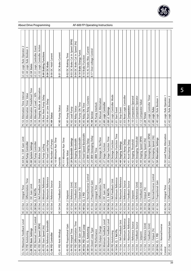
CL-7
4 M
axim
um F
eedb
ack
Leve
lXC
-22
Ext.
1 In
tegr
al T
ime
XC-6
4 Ex
t. 3
Dif.
Gai
n L
imit
PC-5
2 A
ltern
atio
n T
ime
Inte
rval
LC-4
3 Lo
gic
Rule
Ope
rato
r 2
CL-7
9 PI
D A
utot
unin
gXC
-23
Ext.
1 D
iffer
enta
tion
Tim
ePC
-##
Pum
p C
ontr
olle
rPC
-53
Alte
rnat
ion
Tim
er V
alue
LC-4
4 Lo
gic
Rule
Boo
lean
3
CL-8
# PI
D B
asic
Set
tings
XC-2
4 Ex
t. 1
Dif.
Gai
n L
imit
PC-0
# Sy
stem
Set
tings
PC-5
4 A
ltern
atio
n P
rede
fined
Tim
eLC
-5#
Stat
es
CL-8
1 PI
D N
orm
al/
Inve
rse
Cont
rol
XC-3
# Ex
t. C
L 2
Ref./
Fb.
PC-0
0 Pu
mp
Con
trol
ler
PC-5
5 A
ltern
ate
if Lo
ad <
50%
LC-5
1 Lo
gic
Cont
rolle
r Ev
ent
CL-8
2 PI
D S
tart
Spe
ed [R
PM]
XC-3
0 Ex
t. 2
Ref
./Fee
dbac
k U
nit
PC-0
2 M
otor
Sta
rtPC
-56
Stag
ing
Mod
e at
Alte
rnat
ion
LC-5
2 Lo
gic
Cont
rolle
r A
ctio
n
CL-8
3 PI
D S
tart
Spe
ed [H
z]XC
-31
Ext.
2 M
inim
um R
efer
ence
PC-0
4 Pu
mp
Cyc
ling
PC-5
8 Ru
n N
ext
Pum
p D
elay
B-##
Bra
king
Fun
ctio
ns
CL-8
4 O
n R
efer
ence
Ban
dwid
thXC
-32
Ext.
2 M
axim
um R
efer
ence
PC-0
5 Fi
xed
Lea
d P
ump
PC-5
9 Ru
n o
n L
ine
Del
ayB-
0# D
C-Br
ake
CL-9
# PI
D C
ontr
olle
rXC
-33
Ext.
2 R
efer
ence
Sou
rce
PC-0
6 N
umbe
r of
Pum
psPC
-8#
Stat
usB-
00 D
C H
old
Cur
rent
CL-9
1 PI
D A
nti W
indu
pXC
-34
Ext.
2 F
eedb
ack
Sour
ce
PC-1
0 M
inim
um R
un T
ime
Ove
rrid
ePC
-80
Pum
p S
tatu
sB-
01 D
C B
rake
Cur
rent
CL-9
3 PI
D P
ropo
rtio
nal G
ain
XC-3
5 Ex
t. 2
Setp
oint
PC-1
1 M
inim
um R
un T
ime
Ove
rrid
e Va
lue
PC-8
1 Pu
mp
Sta
tus
B-02
DC
Bra
king
Tim
e
CL-9
4 PI
D In
tegr
al T
ime
XC-3
7 Ex
t. 2
Ref
eren
ce [U
nit]
PC-2
# Ba
ndw
idth
Set
tings
PC-8
2 Le
ad P
ump
B-03
DC
Bra
ke C
ut In
Spe
ed [R
PM]
CL-9
5 PI
D D
iffer
entia
tion
Tim
eXC
-38
Ext.
2 Fe
edba
ck [U
nit]
PC-2
0 St
agin
g B
andw
idth
PC-8
3 Re
lay
Stat
usB-
04 D
C B
rake
Cut
In S
peed
[Hz]
CL-9
6 PI
D D
iff. G
ain
Lim
itXC
-39
Ext.
2 O
utpu
t [%
]PC
-21
Ove
rrid
e Ba
ndw
idth
PC-8
4 Pu
mp
ON
Tim
eB-
1# B
rake
Ene
rgy
Func
t.
XC-#
# Ex
t. P
ID C
lose
d L
oop
XC-4
# Ex
t. C
L 2
PID
PC-2
2 Fi
xed
Spe
ed B
andw
idth
PC-8
5 Re
lay
ON
Tim
eB-
10 B
rake
Fun
ctio
n
XC-0
# Ex
t. CL
Aut
otun
ing
XC-4
0 Ex
t. 2
Nor
mal
/Inve
rse
Cont
rol
PC-2
3 SB
W S
tagi
ng D
elay
PC-8
6 Re
set
Rela
y Co
unte
rsB-
16 A
C b
rake
Max
. Cur
rent
XC-0
0 Cl
osed
Loo
p T
ype
XC-4
1 Ex
t. 2
Prop
ortio
nal G
ain
PC-2
4 SB
W D
esta
ging
Del
ayPC
-9#
Serv
ice
B-17
Ove
r-vo
ltage
Con
trol
XC-0
1 PI
D P
erfo
rman
ceXC
-42
Ext.
2 In
tegr
al T
ime
PC-2
5 O
BW T
ime
PC-9
0 Pu
mp
Inte
rlock
XC-0
2 PI
D O
utpu
t Ch
ange
XC-4
3 Ex
t. 2
Diff
eren
tatio
n T
ime
PC-2
6 D
esta
ge A
t N
o-Fl
owPC
-91
Man
ual A
ltern
atio
n
XC-0
3 M
inim
um F
eedb
ack
Leve
lXC
-44
Ext.
2 D
if. G
ain
Lim
itPC
-27
Stag
e Fu
nctio
nLC
-##
Logi
c Co
ntro
ller
XC-0
4 M
axim
um F
eedb
ack
Leve
lXC
-5#
Ext.
CL
3 Re
f./Fb
.PC
-28
Stag
e Fu
nctio
n T
ime
LC-0
# LC
Set
tings
XC-0
9 PI
D A
utot
unin
gXC
-50
Ext.
3 R
ef./F
eedb
ack
Uni
tPC
-29
Des
tage
Fun
ctio
nLC
-00
Logi
c Co
ntro
ller
Mod
e
XC-1
# Ex
t. C
L 1
Ref./
Fb.
XC-5
1 Ex
t. 3
Min
imum
Ref
eren
cePC
-30
Des
tage
Fun
ctio
n T
ime
LC-0
1 St
art
Even
t
XC-1
0 Ex
t. 1
Ref
./Fee
dbac
k U
nit
XC-5
2 Ex
t. 3
Max
imum
Ref
eren
cePC
-4#
Stag
ing
Set
tings
LC-0
2 St
op E
vent
XC-1
1 Ex
t. 1
Min
imum
Ref
eren
ceXC
-53
Ext.
3 R
efer
ence
Sou
rce
PC-4
0 D
ecel
Ram
p D
elay
LC-0
3 Re
set
Logi
c Co
ntro
ller
XC-1
2 Ex
t. 1
Max
imum
Ref
eren
ceXC
-54
Ext.
3 F
eedb
ack
Sour
cePC
-41
Acc
el R
amp
Del
ayLC
-1#
Com
para
tors
XC-1
3 Ex
t. 1
Ref
eren
ce S
ourc
eXC
-55
Ext.
3 S
etpo
int
PC-4
2 St
agin
g T
hres
hold
LC-1
0 Co
mpa
rato
r O
pera
nd
XC-1
4 Ex
t. 1
Fee
dbac
k So
urce
XC-5
7 Ex
t. 3
Ref
eren
ce [U
nit]
PC-4
3 D
esta
ging
Thr
esho
ldLC
-11
Com
para
tor
Ope
rato
r
XC-1
5 Ex
t. 1
Setp
oint
XC-5
8 Ex
t. 3
Feed
back
[Uni
t]PC
-44
Stag
ing
Spe
ed [R
PM]
LC-1
2 Co
mpa
rato
r Va
lue
XC-1
7 Ex
t. 1
Ref
eren
ce [U
nit]
XC-5
9 Ex
t. 3
Out
put
[%]
PC-4
5 St
agin
g S
peed
[Hz]
LC-2
# Ti
mer
s
XC-1
8 Ex
t. 1
Feed
back
[Uni
t]XC
-6#
Ext.
CL 3
PID
PC-4
6 D
esta
ging
Spe
ed [R
PM]
LC-2
0 Lo
gic
Cont
rolle
r Ti
mer
XC-1
9 Ex
t. 1
Out
put
[%]
XC-6
0 Ex
t. 3
Nor
mal
/Inve
rse
Cont
rol
PC-4
7 D
esta
ging
Spe
ed [H
z]LC
-4#
Logi
c Ru
les
XC-2
# Ex
t. C
L 1
PID
XC-6
1 Ex
t. 3
Pro
port
iona
l Gai
nPC
-5#
Alte
rnat
ion
Set
tings
LC-4
0 Lo
gic
Rule
Boo
lean
1
XC-2
0 Ex
t. 1
Nor
mal
/Inve
rse
Cont
rol
XC-6
2 Ex
t. 3
Inte
gral
Tim
ePC
-50
Lead
Pum
p A
ltern
atio
nLC
-41
Logi
c Ru
le O
pera
tor
1
XC-2
1 Ex
t. 1
Prop
ortio
nal G
ain
XC-6
3 Ex
t. 3
Diff
eren
tatio
n T
ime
PC-5
1 A
ltern
atio
n E
vent
LC-4
2 Lo
gic
Rule
Boo
lean
2
About Drive Programming AF-600 FP Operating Instructions
39
5 5

5.6 Remote Programming with DCT-10
GE has a software program available for developing,storing, and transferring drive programming. The DCT-10allows the user to connect a PC to the drive and performlive programming rather than using the keypad. Also, alldrive programming can be done off-line and simplydownloaded into drive. Or the entire drive profile can beloaded onto the PC for back up storage or analysis.
The USB connector or RS-485 terminal are available forconnecting to the drive.
About Drive Programming AF-600 FP Operating Instructions
40
55
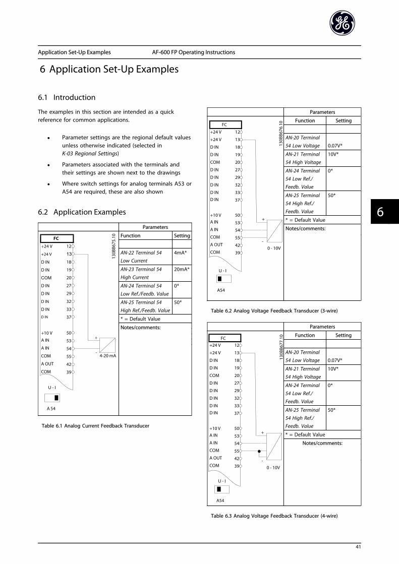
6 Application Set-Up Examples
6.1 Introduction
The examples in this section are intended as a quickreference for common applications.
• Parameter settings are the regional default valuesunless otherwise indicated (selected inK-03 Regional Settings)
• Parameters associated with the terminals andtheir settings are shown next to the drawings
• Where switch settings for analog terminals A53 orA54 are required, these are also shown
6.2 Application Examples
Parameters
Function Setting
AN-22 Terminal 54Low Current
4mA*
AN-23 Terminal 54High Current
20mA*
AN-24 Terminal 54Low Ref./Feedb. Value
0*
AN-25 Terminal 54
High Ref./Feedb. Value
50*
* = Default Value
Notes/comments:
Table 6.1 Analog Current Feedback Transducer
Parameters
Function Setting
AN-20 Terminal54 Low Voltage 0.07V*
AN-21 Terminal54 High Voltage
10V*
AN-24 Terminal54 Low Ref./Feedb. Value
0*
AN-25 Terminal54 High Ref./Feedb. Value
50*
* = Default Value
Notes/comments:
Table 6.2 Analog Voltage Feedback Transducer (3-wire)
Parameters
Function Setting
AN-20 Terminal54 Low Voltage 0.07V*
AN-21 Terminal54 High Voltage
10V*
AN-24 Terminal
54 Low Ref./Feedb. Value
0*
AN-25 Terminal
54 High Ref./Feedb. Value
50*
* = Default Value
Notes/comments:
Table 6.3 Analog Voltage Feedback Transducer (4-wire)
Application Set-Up Examples AF-600 FP Operating Instructions
41
6 6

Parameters
Function Setting
AN-10 Terminal53 Low Voltage 0.07V*
AN-11 Terminal53 High Voltage
10V*
AN-14 Terminal53 Low Ref./Feedb. Value
0*
AN-15 Terminal53 High Ref./Feedb. Value
50*
* = Default Value
Notes/comments:
Table 6.4 Analog Speed Reference (Voltage)
Parameters
Function Setting
AN-12 Terminal53 Low Current
4mA*
AN-13 Terminal
53 High Current
20mA*
AN-14 Terminal
53 Low Ref./Feedb. Value
0*
AN-15 Terminal53 High Ref./Feedb. Value
50*
* = Default Value
Notes/comments:
Table 6.5 Analog Speed Reference (Current)
Parameters
Function Setting
E-01 Terminal 18Digital Input
[8] Start*
E-03 Terminal 27Digital Input
[7] ExternalInterlock
* = Default Value
Notes/comments:
Table 6.6 Run/Stop Command with External Interlock
Parameters
Function Setting
E-01 Terminal 18
Digital Input
[8] Start*
E-03 Terminal 27
Digital Input
[0] No
operation*
* = Default Value
Notes/comments:
Table 6.7 Run/Stop Command without External Interlock
Application Set-Up Examples AF-600 FP Operating Instructions
42
66
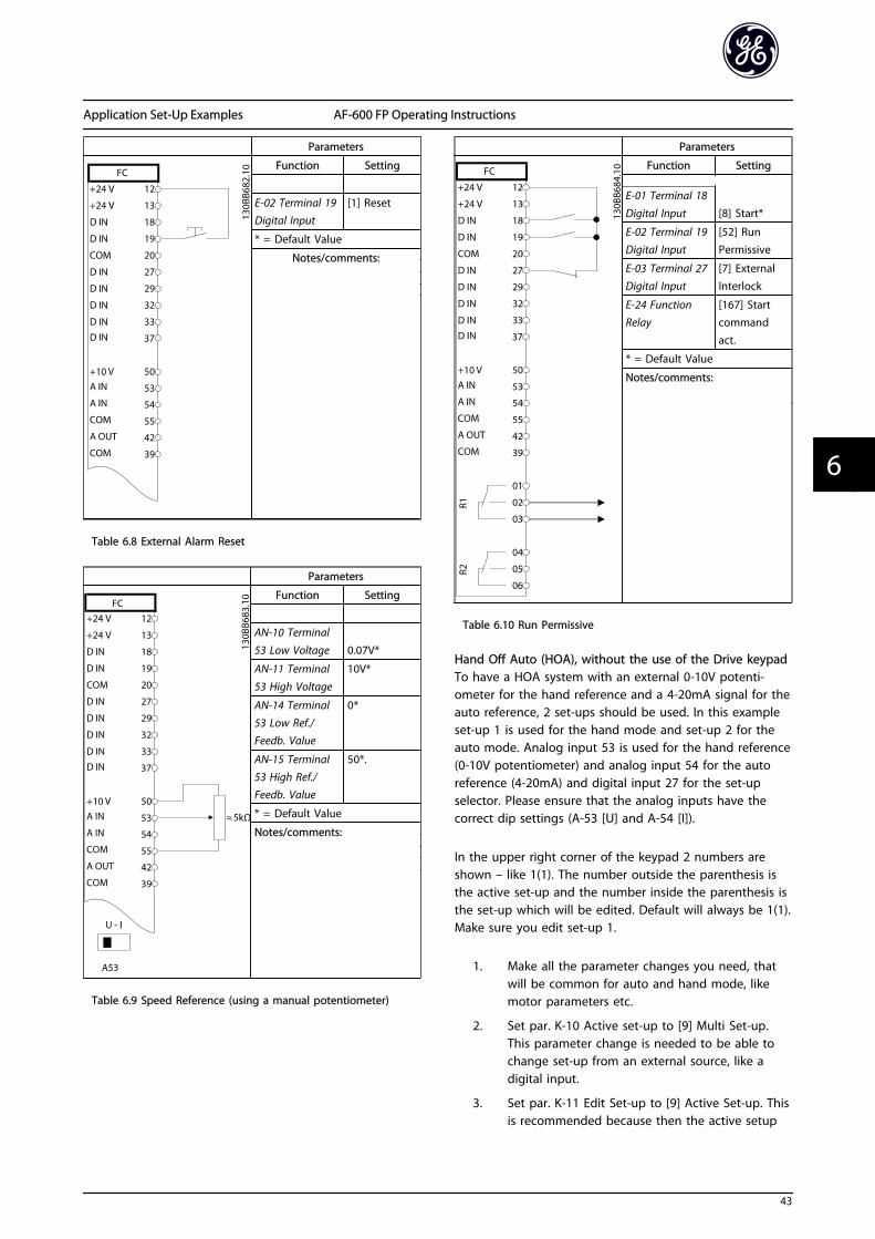
Parameters
Function Setting
E-02 Terminal 19Digital Input
[1] Reset
* = Default Value
Notes/comments:
Table 6.8 External Alarm Reset
Parameters
Function Setting
AN-10 Terminal
53 Low Voltage 0.07V*
AN-11 Terminal
53 High Voltage
10V*
AN-14 Terminal53 Low Ref./Feedb. Value
0*
AN-15 Terminal53 High Ref./Feedb. Value
50*.
* = Default Value
Notes/comments:
Table 6.9 Speed Reference (using a manual potentiometer)
Parameters
Function Setting
E-01 Terminal 18
Digital Input [8] Start*
E-02 Terminal 19Digital Input
[52] RunPermissive
E-03 Terminal 27Digital Input
[7] ExternalInterlock
E-24 FunctionRelay
[167] Startcommandact.
* = Default Value
Notes/comments:
Table 6.10 Run Permissive
Hand Off Auto (HOA), without the use of the Drive keypadTo have a HOA system with an external 0-10V potenti-ometer for the hand reference and a 4-20mA signal for theauto reference, 2 set-ups should be used. In this exampleset-up 1 is used for the hand mode and set-up 2 for theauto mode. Analog input 53 is used for the hand reference(0-10V potentiometer) and analog input 54 for the autoreference (4-20mA) and digital input 27 for the set-upselector. Please ensure that the analog inputs have thecorrect dip settings (A-53 [U] and A-54 [I]).
In the upper right corner of the keypad 2 numbers areshown – like 1(1). The number outside the parenthesis isthe active set-up and the number inside the parenthesis isthe set-up which will be edited. Default will always be 1(1).Make sure you edit set-up 1.
1. Make all the parameter changes you need, thatwill be common for auto and hand mode, likemotor parameters etc.
2. Set par. K-10 Active set-up to [9] Multi Set-up.This parameter change is needed to be able tochange set-up from an external source, like adigital input.
3. Set par. K-11 Edit Set-up to [9] Active Set-up. Thisis recommended because then the active setup
Application Set-Up Examples AF-600 FP Operating Instructions
43
6 6

will always be the set-up that is edited. If youprefer you can also ignore this and manuallycontrol what set-up you want to edit throughpar. K-11.
4. Set par. E-03 Terminal 27 Digital Input to [23] Set-up select bit 0. When terminal 27 is OFF, set-up 1(hand) is active, when it is ON, set-up 2 (auto) isactive.
5. Set par. F-01 Frequency Setting 1 to Analog input53 (hand mode).
6. Copy set-up 1 to set-up 2. Set par. K-51 Set upCopy to [2] Copy to set-up 2. Now setup 1 and 2are identical.
7. If you need to be able to change between handand auto mode while the motor is running youwill have to link the 2 set-ups together. Set par.K-12 This Set-up Linked to to [2] set-up 2.
8. Change to set-up 2 by setting input 27 ON (if par.K-11 is [9]) or by setting par. K-11 Edit Set-up toset-up 2.
9. Set par. F-01 Frequency Setting 1 to Analog input54 (auto mode). If you want different settings inhand and auto mode, like different accel/decelramps, speed limits etc. you can now programmethem. You just have to make sure you edit thecorrect set-up. Set-up 1 is Hand mode and set-up2 is Auto mode.
Parameters
Function Setting
E-01 Terminal 18
Digital Input [8] Start*
E-03 Terminal 27
Digital Input
[23[ Set-up
select bit 0
* = Default Value
Notes/comments:GE 30mm HOA Cat# (1)104PSG34B & (3) CR104PXC1
Table 6.11 HOA
Parameters
Function Setting
O-30 Protocol Drive*
O-31 Address 1*
O-32 Drive PortBaud Rate
9600*
* = Default Value
Notes/comments:
Select protocol, address andbaud rate in the abovementioned parameters.
Table 6.12 RS-485 Network Connection (N2, FLN, Modbus RTU, Drive)
CAUTIONThermistors must use reinforced or double insulation tomeet PELV insulation requirements.
Application Set-Up Examples AF-600 FP Operating Instructions
44
66

Parameters
Function Setting
F-10 ElectronicOverload
[2]Thermistortrip
F-12 MotorThermistor Input
[1] Analoginput 53
* = Default Value
Notes/comments:If only a warning is desired,F-10 Electronic Overload shouldbe set to [1] Thermistor warning.
Table 6.13 Motor Thermistor
Parameters
Function Setting
E-02 Terminal 19Digital Input
[37] Fire
mode
FB-00 Fire ModeFunction
[0] Disabled*
FB-01 Fire Mode
Configuration
[0] Open
Loop*
FB-02 Fire ModeUnit
[3] Hz*
FB-03 Fire ModeMin Reference
0Hz*
FB-04 Fire ModeMax Reference
50Hz*
FB-05 Fire ModePreset Reference
0%*
FB-06 Fire Mode
Reference Source
[0] No
function*
FB-07 Fire Mode
Feedback Source
[0] No
function*
FB-09 Fire ModeAlarm Handling
[1] Trip,CriticalAlarms*
* = Default Value
Notes/comments:Parameters to setup Fire Modeare all in the FB-## group.
Table 6.14 Fire Mode
Application Set-Up Examples AF-600 FP Operating Instructions
45
6 6

7 Status Messages
7.1 Status Display
When the drive is in status mode, status messages aregenerated automatically from within the drive and appearin the bottom line of the display (see Illustration 7.1.)
Illustration 7.1 Status Display
a. The first word on the status line indicates wherethe stop/start command originates.
b. The second word on the status line indicateswhere the speed control originates.
c. The last part of the status line gives the presentdrive status. These show the operational modethe drive is in.
NOTEIn auto/remote mode, the drive requires externalcommands to execute functions.
7.2 Status Message Definitions Table
The next three tables define the meaning of the statusmessage display words.
Operation Mode
Off The drive does not react to any control signaluntil [Auto] or [Hand] is pressed.
Auto The drive is controlled from the controlterminals and/or the serial communication.
Hand The drive can be controlled by the navigationkeys on the keypad. Stop commands, reset,reversing, DC brake, and other signals appliedto the control terminals can override localcontrol.
Reference Site
Remote The speed reference is given from external
signals, serial communication, or internalpreset references.
Local The drive uses [Hand] control or referencevalues from the keypad.
Operation StatusAC Brake AC Brake was selected in B-10 Brake Function.
The AC brake over-magnetizes the motor toachieve a controlled slow down.
Auto Tune finish
OK
Auto Tune was carried out successfully.
Auto Tune ready Auto Tune is ready to start. Press [Hand] to
start.
Auto Tunerunning
Auto Tune process is in progress.
Coast • Coast inverse was selected as a function
for a digital input. The correspondingterminal is not connected.
• Coast activated by serial communication
Ctrl. Ramp-down Control Ramp-down was selected in SP-10 Linefailure.
• The mains voltage is below the value setin SP-11 Line Voltage at Input Fault atmains fault
• The drive ramps down the motor using a
controlled ramp down
Current High The drive output current is above the limit setin H-71 Warning Current High.
Current Low The drive output current is below the limit setin H-70 Warning Current Low
Status Messages AF-600 FP Operating Instructions
46
77

Operation StatusDC Hold DC hold is selected in H-80 Function at Stop
and a stop command is active. The motor isheld by a DC current set in B-00 DC HoldCurrent.
DC Stop The motor is held with a DC current (B-01 DCBrake Current) for a specified time (B-02 DCBraking Time).
• DC Brake is activated in B-03 DC Brake CutIn Speed [RPM] and a Stop command isactive.
• DC Brake (inverse) is selected as a functionfor a digital input. The correspondingterminal is not active.
• The DC Brake is activated via serialcommunication.
Feedback high The sum of all active feedbacks is above thefeedback limit set in H-77 Warning FeedbackHigh.
Feedback low The sum of all active feedbacks is below thefeedback limit set in H-76 Warning FeedbackLow.
Freeze output The remote reference is active which holdsthe present speed.
• Freeze output was selected as a functionfor a digital input. The correspondingterminal is active. Speed control is onlypossible via the terminal functions speedup and speed down.
• Hold ramp is activated via serial communi-cation.
Freeze outputrequest
A freeze output command has been given,but the motor will remain stopped until a runpermissive signal is received.
Freeze ref. Freeze Reference was chosen as a function fora digital input. The corresponding terminal isactive. The drive saves the actual reference.Changing the reference is now only possiblevia terminal functions speed up and speeddown.
Jog request A jog command has been given, but the
motor will be stopped until a run permissivesignal is received via a digital input.
Jogging The motor is running as programmed in
C-21 Jog Speed [RPM].
• Jog was selected as function for a digital
input. The corresponding terminal (e.g.Terminal 29) is active.
• The Jog function is activated via the serialcommunication.
• The Jog function was selected as areaction for a monitoring function (e.g. Nosignal). The monitoring function is active.
Operation StatusOVC control Overvoltage control was activated in B-17 Over-
voltage Control. The connected motor issupplying the drive with generative energy.The overvoltage control adjusts the V/Hz ratioto run the motor in controlled mode and toprevent the drive from tripping.
PowerUnit Off (For frequency converters with an external 24Vpower supply installed only.) Mains supply tothe drive is removed, but the control card issupplied by the external 24V.
Protection md Protection mode is active. The unit has
detected a critical status (an overcurrent orovervoltage).
• To avoid tripping, switching frequency is
reduced to 4kHz.
• If possible, protection mode ends afterapproximately 10sec.
• Protection mode can be restricted inSP-26 Trip Delay at Drive Fault
QStop The motor is decelerating using C-23 QuickStop Decel Time.
• Quick stop inverse was chosen as a function
for a digital input. The correspondingterminal is not active.
• The quick stop function was activated viaserial communication.
Ramping The motor is accelerating/decelerating using
the active Ramp Up/Down. The reference, alimit value or a standstill is not yet reached.
Ref. high The sum of all active references is above the
reference limit set in H-75 Warning ReferenceHigh.
Ref. low The sum of all active references is below the
reference limit set in H-74 Warning ReferenceLow .
Run on ref. The drive is running in the reference range.
The feedback value matches the setpointvalue.
Run request A start command has been given, but themotor is stopped until a run permissive signalis received via digital input.
Running The motor is driven by the drive.
Sleep Mode The energy saving function is enabled. Thismeans that at present the motor has stopped,but that it will restart automatically whenrequired.
Speed high Motor speed is above the value set in
H-73 Warning Speed High.
Speed low Motor speed is below the value set in
H-72 Warning Speed Low.
Standby In Auto mode, the drive will start the motor
with a start signal from a digital input or serialcommunication.
Status Messages AF-600 FP Operating Instructions
47
7 7

Operation StatusStart delay In F-24 Holding Time, a delay starting time was
set. A start command is activated and themotor will start after the start delay timeexpires.
Start fwd/rev Start forward and start reverse were selected
as functions for two different digital inputs.The motor will start in forward or reversedepending on which corresponding terminal is
activated.
Stop The drive has received a stop command from
the keypad, digital input or serial communi-cation.
Trip An alarm occurred and the motor is stopped.Once the cause of the alarm is cleared, thedrive can be reset manually by pressing[Reset] or remotely by control terminals orserial communication.
Trip lock An alarm occurred and the motor is stopped.Once the cause of the alarm is cleared, powermust be cycled to the drive. The drive canthen be reset manually by pressing [Reset] orremotely by control terminals or serialcommunication.
Status Messages AF-600 FP Operating Instructions
48
77

8 Warnings and Alarms
8.1 System Monitoring
The drive monitors the condition of its input power,output, and motor factors as well as other systemperformance indicators. A warning or alarm may notnecessarily indicate a problem internal to the drive itself. Inmany cases it indicates failure conditions from inputvoltage, motor load or temperature, external signals, orother areas monitored by the frequency converter’sinternal logic. Be sure to investigate those areas exterior tothe drive as indicated in the alarm or warning.
8.2 Warning and Alarm Types
WarningsA warning is issued when an alarm condition is impendingor when an abnormal operating condition is present andmay result in the drive issuing an alarm. A warning clearsby itself when the abnormal condition is removed.
AlarmsTripAn alarm is issued when the drive is tripped, that is, thedrive suspends operation to prevent drive or systemdamage. The motor will coast to a stop. The drive logicwill continue to operate and monitor the drive status. Afterthe fault condition is remedied, the drive can be reset. Itwill then be ready to start operation again.
A trip can be reset in any of 4 ways:
• Press [RESET] on the keypad
• Digital reset input command
• Serial communication reset input command
• Auto reset
Trip-lockAn alarm that causes the drive to trip-lock requires thatinput power be cycled. The motor will coast to a stop. Thedrive logic will continue to operate and monitor the drivestatus. Remove input power to the drive and correct thecause of the fault, then restore power. This action puts thedrive into a trip condition as described above and may bereset in any of those 4 ways.
8.3 Warning and Alarm Displays
An alarm or trip-lock alarm will flash on display along withthe alarm number.
In addition to the text and alarm code on the drivedisplay, the status indicator lights operate.
Warn. LED Alarm LED
Warning ON OFF
Alarm OFF ON (Flashing)
Trip-Lock ON ON (Flashing)
Warnings and Alarms AF-600 FP Operating Instructions
49
8 8

8.4 Warning and Alarm Definitions
Table 8.1 defines whether a warning is issued prior to an alarm, and whether the alarm trips the unit or trip locks the unit.
No. Description Warning Alarm/Trip Alarm/Trip Lock Parameter Reference1 10 Volts low X
2 Live zero error (X) (X) AN-01 Live Zero Timeout
Function
4 Mains phase loss (X) (X) (X) SP-12 Function at Line
Imbalance
5 DC link voltage high X
6 DC link voltage low X
7 DC over voltage X X
8 DC under voltage X X
9 Inverter overloaded X X
10 Motor Electronic Thermal Overload overtemperature
(X) (X) F-10 Electronic Overload
11 Motor thermistor over temperature (X) (X) F-10 Electronic Overload
12 Torque limit X X
13 Over Current X X X
14 Earth fault X X X
15 Hardware mismatch X X
16 Short Circuit X X
17 Control word timeout (X) (X) O-04 Control WordTimeout Function
18 Start Failed
23 Internal Fan Fault X
24 External Fan Fault X SP-53 Fan Monitor
29 Drive over temperature X X X
30 Motor phase U missing (X) (X) (X) H-78 Missing Motor PhaseFunction
31 Motor phase V missing (X) (X) (X) H-78 Missing Motor PhaseFunction
32 Motor phase W missing (X) (X) (X) H-78 Missing Motor Phase
Function
33 Inrush fault X X
34 Fieldbus communication fault X X
35 Option Fault X X
36 Mains failure X X
38 Internal fault X X
39 Heatsink sensor X X
40 Overload of Digital Output Terminal 27 (X) E-00 Digital I/O Mode,E-51 Terminal 27 Mode
41 Overload of Digital Output Terminal 29 (X) E-00 Digital I/O Mode,E-52 Terminal 29 Mode
42 Overload of Digital Output On X30/6 (X) E-56 Term X30/6 Digi Out(OPCGPIO)
42 Overload of Digital Output On X30/7 (X) E-57 Term X30/7 Digi Out(OPCGPIO)
45 45 Earth Fault 2
46 Pwr. card supply X X
47 24V supply low X X X
48 1.8V supply low X X
49 Speed limit X (X) H-36 Trip Speed Low [RPM]
Warnings and Alarms AF-600 FP Operating Instructions
50
88

No. Description Warning Alarm/Trip Alarm/Trip Lock Parameter Reference50 Auto Tune calibration failed X
51 Auto Tune check Unom and Inom X
52 Auto Tune low Inom X
53 Auto Tune motor too big X
54 Auto Tune motor too small X
55 Auto Tune Parameter out of range X
56 Auto Tune interrupted by user X
57 Auto Tune timeout X
58 Auto Tune internal fault X X
59 Current limit X
60 External Interlock X
62 Output Frequency at Maximum Limit X
64 Voltage Limit X
65 Control Board Over-temperature X X X
66 Heat sink Temperature Low X
67 Option Configuration has Changed X
69 Pwr. Card Temp X X
70 Illegal Drive configuration X
76 Power Unit Setup X
79 Illegal PS config X X
80 Drive Initialized to Default Value X
91 Analog input 54 wrong settings X
92 NoFlow X X AP-2#
93 Dry Pump X X AP-2#
94 End of Curve X X AP-5#
95 Broken Belt X X AP-6#
96 Start Delayed X AP-7#
97 Stop Delayed X AP-7#
98 Clock Fault X K-7#
201 Fire M was Active
202 Fire M Limits Exceeded
203 Missing Motor
204 Locked Rotor
243 Brake IGBT X X
244 Heatsink temp X X X
245 Heatsink sensor X X
246 Pwr.card supply X X
247 Pwr.card temp X X
248 Illegal PS config X X
250 New spare parts X
251 New Type Code X X
Table 8.1 Alarm/Warning code list
(X) Dependent on parameter1) Cannot be Auto reset via H-04 Auto-Reset (Times)8.4.1 Fault Messages
The warning/alarm information below defines the warning/alarm condition, provides the probable cause for thecondition, and details a remedy or troubleshootingprocedure.
WARNING 1, 10 Volts lowThe control card voltage is below 10 V from terminal 50.
Remove some of the load from terminal 50, as the 10 Vsupply is overloaded. Max. 15 mA or minimum 590 Ω.
This condition can be caused by a short in a connectedpotentiometer or improper wiring of the potentiometer.
Troubleshooting: Remove the wiring from terminal 50. Ifthe warning clears, the problem is with the customerwiring. If the warning does not clear, replace the controlcard.
Warnings and Alarms AF-600 FP Operating Instructions
51
8 8

WARNING/ALARM 2, Live zero errorThis warning or alarm will only appear if programmed bythe user in AN-01 Live Zero Timeout Function. The signal onone of the analog inputs is less than 50% of the minimumvalue programmed for that input. This condition can becaused by broken wiring or faulty device sending thesignal.
TroubleshootingCheck connections on all the analog inputterminals. Control card terminals 53 and 54 forsignals, terminal 55 common. OPCGPIO terminals11 and 12 for signals, terminal 10 common.OPCAIO terminals 1, 3, 5 for signals, terminals 2,4, 6 common).
Check that the drive programming and switchsettings match the analog signal type.
Perform Input Terminal Signal Test.
WARNING/ALARM 4, Mains phase lossA phase is missing on the supply side, or the mainsvoltage imbalance is too high. This message also appearsfor a fault in the input rectifier on the drive. Options areprogrammed at SP-12 Function at Line Imbalance.
Troubleshooting: Check the supply voltage and supplycurrents to the drive.
WARNING 5, DC link voltage highThe intermediate circuit voltage (DC) is higher than thehigh voltage warning limit. The limit is dependent on thedrive voltage rating. The unit is still active.
WARNING 6, DC link voltage lowThe intermediate circuit voltage (DC) is lower than the lowvoltage warning limit. The limit is dependent on the drivevoltage rating. The unit is still active.
WARNING/ALARM 7, DC overvoltageIf the intermediate circuit voltage exceeds the limit, thedrive trips after a time.
TroubleshootingConnect a brake resistor
Extend the ramp time
Change the ramp type
Activate the functions in B-10 Brake Function
Increase SP-26 Trip Delay at Drive Fault
WARNING/ALARM 8, DC under voltageIf the intermediate circuit voltage (DC link) drops belowthe under voltage limit, the drive checks if a 24V DCbackup supply is connected. If no 24V DC backup supply isconnected, the drive trips after a fixed time delay. Thetime delay varies with unit size.
Troubleshooting:Check that the supply voltage matches the drivevoltage.
Perform input voltage test
Perform soft charge circuit test
WARNING/ALARM 9, Inverter overloadThe drive is about to cut out because of an overload (toohigh current for too long). The counter for electronic,thermal inverter protection gives a warning at 98% andtrips at 100%, while giving an alarm. The drive cannot bereset until the counter is below 90%.The fault is that the drive is overloaded by more than100% for too long.
TroubleshootingCompare the output current shown on thekeypad with the drive rated current.
Compare the output current shown on thekeypad with measured motor current.
Display the Thermal Drive Load on the keypadand monitor the value. When running above thedrive continuous current rating, the countershould increase. When running below the drivecontinuous current rating, the counter shoulddecrease.
See the derating section in the Design Guide for moredetails if a high switching frequency is required.
WARNING/ALARM 10, Motor overload temperatureAccording to the electronic thermal protection, the motoris too hot. Select whether the drive gives a warning or analarm when the counter reaches 100% in F-10 ElectronicOverload . The fault occurs when the motor is overloadedby more than 100% for too long.
TroubleshootingCheck for motor overheating.
Check if the motor is mechanically overloaded
Check that the motor current set in P-03 MotorCurrent is correct.
Ensure that Motor data in parameters P-02, P-03,P-06, P-07, F-04 and F-05 are set correctly.
If an external fan is in use, check in F-11 MotorExternal Fan that it is selected.
Running Auto tune in P-04 Auto Tune may tunethe drive to the motor more accurately andreduce thermal loading.
WARNING/ALARM 11, Motor thermistor over tempThe thermistor might be disconnected. Select whether thedrive gives a warning or an alarm in F-10 ElectronicOverload .
Warnings and Alarms AF-600 FP Operating Instructions
52
88

TroubleshootingCheck for motor overheating.
Check if the motor is mechanically overloaded.
When using terminal 53 or 54, check that thethermistor is connected correctly between eitherterminal 53 or 54 (analog voltage input) andterminal 50 (+10V supply) and that the terminalswitch for 53 or 54 is set for voltage. CheckF-12 Motor Thermistor Input selects terminal 53 or54.
When using digital inputs 18 or 19, check thatthe thermistor is connected correctly betweeneither terminal 18 or 19 (digital input PNP only)and terminal 50. Check F-12 Motor ThermistorInput selects terminal 18 or 19.
WARNING/ALARM 12, Torque limitThe torque has exceeded the value in F-40 Torque Limiter(Driving) or the value in F-41 Torque Limiter (Braking).SP-25 Trip Delay at Torque Limit can change this from awarning only condition to a warning followed by an alarm.
TroubleshootingIf the motor torque limit is exceeded during rampup, extend the ramp up time.
If the generator torque limit is exceeded duringramp down, extend the ramp down time.
If torque limit occurs while running, possiblyincrease the torque limit. Be sure the system canoperate safely at a higher torque.
Check the application for excessive current drawon the motor.
WARNING/ALARM 13, Over currentThe inverter peak current limit (approximately 200% of therated current) is exceeded. The warning lasts about 1.5secs., then the drive trips and issues an alarm. This faultmay be caused by shock loading or fast acceleration withhigh inertia loads. If extended mechanical brake control isselected, trip can be reset externally.
Troubleshooting:
Remove power and check if the motor shaft canbe turned.
Check that the motor size matches the drive.
Check parameters P-02, P-03, P-06, P-07, F-04 andF-05. for correct motor data.
ALARM 14, Earth (ground) faultThere is current from the output phases to earth, either inthe cable between the drive and the motor or in themotor itself.
Troubleshooting:Remove power to the drive and repair the earthfault.
Check for earth faults in the motor by measuringthe resistance to ground of the motor leads andthe motor with a megohmmeter.
ALARM 15, Hardware mismatchA fitted option is not operational with the present controlboard hardware or software.
Record the value of the following parameters and contactyour GE supplier:
ID-40 Drive Type
ID-41 Power Section
ID-42 Voltage
ID-43 Software Version
ID-45 Actual Typecode String
ID-49 SW ID Control Card
ID-50 SW ID Power Card
ID-60 Option Mounted
ID-61 Option SW Version (for each option slot)
ALARM 16, Short circuitThere is short-circuiting in the motor or motor wiring.
Remove power to the drive and repair the short circuit.
WARNING/ALARM 17, Control word timeoutThere is no communication to the drive.The warning will only be active when O-04 Control WordTimeout Function is NOT set to OFF.If O-04 Control Word Timeout Function is set to Stop andTrip, a warning appears and the drive ramps down until itstops then displays an alarm.
Troubleshooting:Check connections on the serial communicationcable.
IncreaseO-03 Control Word Timeout Time
Check the operation of the communicationequipment.
Verify a proper installation based on EMCrequirements.
ALARM 18, Start failedThe speed has not been able to exceed AP-70 CompressorStart Max Speed [RPM] during start within the allowed time.(set in AP-72 Compressor Start Max Time to Trip). This maybe caused by a blocked motor.
WARNING 23, Internal fan faultThe fan warning function is an extra protective functionthat checks if the fan is running/mounted. The fan warningcan be disabled in SP-53 Fan Monitor ([0] Disabled).
For the 4x, 5x and 6x Frame filters, the regulated voltageto the fans is monitored.
Warnings and Alarms AF-600 FP Operating Instructions
53
8 8

Troubleshooting:Check for proper fan operation.
Cycle power to the drive and check that the fanoperates briefly at start up.
Check the sensors on the heatsink and controlcard.
WARNING 24, External fan faultThe fan warning function is an extra protective functionthat checks if the fan is running/mounted. The fan warningcan be disabled in SP-53 Fan Monitor ([0] Disabled).
Troubleshooting:Check for proper fan operation.
Cycle power to the drive and check that the fanoperates briefly at start up.
Check the sensors on the heatsink and controlcard.
ALARM 29, Heatsink tempThe maximum temperature of the heatsink has beenexceeded. The temperature fault will not reset until thetemperature falls below a defined heatsink temperature.The trip and reset points are different based on the drivepower size.
Troubleshooting:Check for the following conditions.
Ambient temperature too high.
Motor cable too long.
Incorrect airflow clearance above and below thedrive
Blocked airflow around the drive.
Damaged heatsink fan.
Dirty heatsink.
ALARM 30, Motor phase U missingMotor phase U between the drive and the motor ismissing.
Remove power from the drive and check motor phase U.
ALARM 31, Motor phase V missingMotor phase V between the drive and the motor ismissing.
Remove power from the drive and check motor phase V.
ALARM 32, Motor phase W missingMotor phase W between the drive and the motor ismissing.
Remove power from the drive and check motor phase W.
ALARM 33, Inrush faultToo many power-ups have occurred within a short timeperiod. Let the unit cool to operating temperature.
WARNING/ALARM 34, communication faultThe network on the communication option card is notworking.
WARNING/ALARM 36, Mains failureThis warning/alarm is only active if the supply voltage tothe drive is lost and SP-10 Line failure is NOT set to [0] NoFunction. Check the fuses to the drive and mains powersupply to the unit.
ALARM 38, Internal faultWhen an internal fault occurs, a code number defined inthe table below is displayed.
TroubleshootingCycle power
Check that the option is properly installed
Check for loose or missing wiring
It may be necessary to contact your GE supplier or servicedepartment. Note the code number for further trouble-shooting directions.
No. Text0 Serial port cannot be initialised. Contact yourGE
supplier or GEService Department.
256-258 Power EEPROM data is defect or too old
512-519 Internal fault. Contact yourGE supplier or GEService Department.
783 Parameter value outside of min/max limits
1024-1284 Internal fault. Contact your GE supplier or the GEService Department.
1299 Option SW in slot A is too old
1300 Option SW in slot B is too old
1302 Option SW in slot C1 is too old
1315 Option SW in slot A is not supported (not allowed)
1316 Option SW in slot B is not supported (not allowed)
1318 Option SW in slot C1 is not supported (notallowed)
1379-2819 Internal fault. Contact yourGE supplier or GEService
Department.
2820 keypad stack overflow
2821 Serial port overflow
2822 USB port overflow
3072-5122 Parameter value is outside its limits
5123 Option in slot A: Hardware incompatible with
control board hardware
5124 Option in slot B: Hardware incompatible with
control board hardware
5125 Option in slot C0: Hardware incompatible withcontrol board hardware
5126 Option in slot C1: Hardware incompatible withcontrol board hardware
5376-6231 Internal fault. Contact yourGE supplier or GEServiceDepartment.
ALARM 39, Heatsink sensorNo feedback from the heatsink temperature sensor.
The signal from the IGBT thermal sensor is not available onthe power card. The problem could be on the power card,on the gate drive card, or the ribbon cable between thepower card and gate drive card.
Warnings and Alarms AF-600 FP Operating Instructions
54
88

WARNING 40, Overload of digital output terminal 27Check the load connected to terminal 27 or remove short-circuit connection. Check E-00 Digital I/O Mode andE-51 Terminal 27 Mode.
WARNING 41, Overload of digital output terminal 29Check the load connected to terminal 29 or remove short-circuit connection. Check E-00 Digital I/O Mode andE-52 Terminal 29 Mode.
WARNING 42, Overload of digital output on X30/6 oroverload of digital output on X30/7For X30/6, check the load connected to X30/6 or removeshort-circuit connection. Check E-56 Term X30/6 Digi Out(OPCGPIO).
For X30/7, check the load connected to X30/7 or removeshort-circuit connection. Check E-57 Term X30/7 Digi Out(OPCGPIO).
ALARM 45, Earth fault 2Earth (ground) fault on start up.
TroubleshootingCheck for proper earthing (grounding) and looseconnections.
Check for proper wire size.
Check motor cables for short-circuits or leakagecurrents.
ALARM 46, Power card supplyThe supply on the power card is out of range.
There are three power supplies generated by the switchmode power supply (SMPS) on the power card: 24V, 5V,+/- 18V. When powered with three phase mains voltage,all three supplied are monitored.
TroubleshootingCheck for a defective power card.
Check for a defective control card.
Check for a defective option card.
If a 24V DC power supply is used, verify propersupply power.
WARNING 47, 24V supply lowThe 24 V DC is measured on the control card. The external24V DC backup power supply may be overloaded,otherwise contact your GE supplier.
WARNING 48, 1.8V supply lowThe 1.8V DC supply used on the control card is outside ofallowable limits. The power supply is measured on thecontrol card. Check for a defective control card. If anoption card is present, check for an overvoltage condition.
WARNING 49, Speed limitWhen the speed is not within the specified range in F-18and F-17, the drive will show a warning. When the speed isbelow the specified limit in H-36 Trip Speed Low [RPM](except when starting or stopping) the drive will trip.
ALARM 50, Auto tune calibration failedContact your GE supplier or GE Service Department.
ALARM 51, Auto tune check Unom and Inom
The settings for motor voltage, motor current, and motorpower are wrong. Check the settings in parameters P-02,P-03, P-06, P-07, F-04 and F-05.
ALARM 52, Auto tune low Inom
The motor current is too low. Check the setting inF-43 Current Limit.
ALARM 53, Auto tune motor too bigThe motor is too big for the Auto tune to operate.
ALARM 54, Auto tune motor too smallThe motor is too small for the Auto tune to operate.
ALARM 55, Auto tune Parameter out of rangeThe parameter values of the motor are outside of theacceptable range. Auto tune will not run.
ALARM 56, Auto tune interrupted by userThe Auto tune has been interrupted by the user.
ALARM 57, Auto tune timeoutTry to restart Auto tune again. Repeated restarts may overheat the motor.
ALARM 58, Auto tune internal faultContact your GE supplier.
WARNING 59, Current limitThe current is higher than the value in F-43 Current Limit.Ensure that Motor data in parameters P-02, P-03, P-06,P-07, F-04 and F-05 are set correctly. Possibly increase thecurrent limit. Be sure the system can operate safely at ahigher limit.
WARNING 60, External interlockA digital input signal is indicating a fault condition externalto the drive. An external interlock has commanded thedrive to trip. Clear the external fault condition. To resumenormal operation, apply 24V DC to the terminalprogrammed for external interlock. Reset the drive.
WARNING 62, Output frequency at maximum limitThe output frequency has reached the value set inF-03 Max Output Frequency 1. Check the application todetermine the cause. Possibly increase the outputfrequency limit. Be sure the system can operate safely at ahigher output frequency. The warning will clear when theoutput drops below the maximum limit.
WARNING/ALARM 65, Control card over temperatureThe cutout temperature of the control card is 80° C.
Troubleshooting
• Check that the ambient operating temperature iswithin limits.
• Check for clogged filters.
• Check fan operation.
• Check the control card.
Warnings and Alarms AF-600 FP Operating Instructions
55
8 8

WARNING 66, Heatsink temperature lowThe drive is too cold to operate. This warning is based onthe temperature sensor in the IGBT module.Increase the ambient temperature of the unit. Also, atrickle amount of current can be supplied to the drivewhenever the motor is stopped by setting B-00 DC HoldCurrent at 5% and H-80 Function at Stop
ALARM 67, Option module configuration has changedOne or more options have either been added or removedsince the last power-down. Check that the configurationchange is intentional and reset the unit.
ALARM 69, Power card temperaturePower cardtemperatureThe temperature sensor on the power card is either toohot or too cold.
TroubleshootingCheck that the ambient operating temperature iswithin limits.
Check for clogged filters.
Check fan operation.
Check the power card.
ALARM 70, Illegal drive configurationThe control card and power card are incompatible. Contactyour supplier with the type code of the unit from thenameplate and the part numbers of the cards to checkcompatibility.
ALARM 80, Unit Restored to Factory SettingsParameter settings are restored to factory settings after amanual reset. Reset the unit to clear the alarm.
ALARM 92, No flowA no-flow condition has been detected in the system.AP-23 No-Flow Function is set for alarm. Troubleshoot thesystem and reset the drive after the fault has been cleared.
ALARM 93, Dry pumpA no-flow condition in the system with the drive operatingat high speed may indicate a dry pump. AP-26 Dry PumpFunction is set for alarm. Troubleshoot the system andreset the drive after the fault has been cleared.
ALARM 94, End of curveFeedback is lower than the set point. This may indicateleakage in the system. AP-50 End of Curve Function is setfor alarm. Troubleshoot the system and reset the driveafter the fault has been cleared.
ALARM 95, Broken beltTorque is below the torque level set for no load, indicatinga broken belt. AP-60 Broken Belt Function is set for alarm.Troubleshoot the system and reset the drive after the faulthas been cleared.
ALARM 96, Start delayedMotor start has been delayed due to short-cycleprotection. AP-76 Interval between Starts is enabled.Troubleshoot the system and reset the drive after the faulthas been cleared.
WARNING 97, Stop delayedStopping the motor has been delayed due to short cycleprotection. AP-76 Interval between Starts is enabled.Troubleshoot the system and reset the drive after the faulthas been cleared.
WARNING 98, Clock faultTime is not set or the RTC clock has failed. Reset the clockin K-70 Date and Time.
WARNING, 200 Fire modeThis indicates the drive is operating in fire mode. Thewarning clears when fire mode is removed. See the firemode data in the alarm log.
WARNING 201, Fire mode was activeThis indicates the drive had entered fire mode. Cyclepower to the unit to remove the warning. See the firemode data in the alarm log.
WARNING 202, Fire mode limits exceededWhile operating in fire mode one or more alarm conditionshave been ignored which would normally trip the unit.Operating in this condition voids unit warranty. Cyclepower to the unit to remove the warning. See the firemode data in the alarm log.
WARNING 203, Missing motorWith a drive operating multi-motors, an under-loadcondition was detected. This could indicate a missingmotor. Inspect the system for proper operation.
WARNING 204, Locked rotorWith a drive operating multi-motors, an overload conditionwas detected. This could indicate a locked rotor. Inspectthe motor for proper operation.
WARNING 250, New spare partA component in the drive has been replaced. Reset thedrive for normal operation.
WARNING 251, New typecodeThe power card or other components have been replacedand the typecode changed. Reset to remove the warningand resume normal operation.
Warnings and Alarms AF-600 FP Operating Instructions
56
88

9 Basic Troubleshooting
9.1 Start Up and Operation
Symptom Possible Cause Test Solution
Display dark / No function
Missing input power See Table 3.1. Check the input power source.
Missing or open fuses or circuitbreaker tripped
See open fuses and tripped circuitbreaker in this table for possiblecauses.
Follow the recommendationsprovided
No power to the keypad Check the keypad cable for properconnection or damage.
Replace the faulty keypad orconnection cable.
Shortcut on control voltage
(terminal 12 or 50) or at controlterminals
Check the 24V control voltage
supply for terminal 12/13 to 20-39or 10V supply for terminal 50 to 55.
Wire the terminals properly.
Wrong contrast setting Press [Status] + Up/Down arrowsto adjust the contrast.
Display (keypad) is defective Test using a different keypad. Replace the faulty keypad orconnection cable.
Internal voltage supply fault orSMPS is defective
Contact supplier.
Intermittent display
Overloaded power supply (SMPS)due to improper control wiring ora fault within the drive
To rule out a problem in thecontrol wiring, disconnect allcontrol wiring by removing theterminal blocks.
If the display stays lit, then theproblem is in the control wiring.Check the wiring for shorts orincorrect connections. If the displaycontinues to cut out, follow theprocedure for display dark.
Motor not running
Service switch open or missing
motor connection
Check if the motor is connected
and the connection is notinterrupted (by a service switch orother devise).
Connect the motor and check the
service switch.
No mains power with 24V DCoption card
If the display is functioning but nooutput, check that mains power isapplied to the drive.
Apply mains power to run the unit.
Keypad Stop Check if [Off] has been pressed. Press [Auto] or [Hand] (dependingon your operation mode) to runthe motor.
Missing start signal (Standby) Check E-01 Terminal 18 Digital Inputfor correct setting for terminal 18(use default setting).
Apply a valid start signal to startthe motor.
Motor coast signal active(Coasting)
Check if a coast inv command isprogrammed for the terminal inparameter group E-0# DigitalInputs
Apply 24V on terminal orprogramm this terminal to Nooperation.
Wrong reference signal source Check reference signal: Local,
remote or bus reference? Presetreference active? Terminalconnection correct? Scaling of
terminals correct? Reference signalavailable?
Program correct settings Check
F-02 Operation Method Set presetreference active in parameterC-05 Multi-step Frequency 1 - 8 .Check for correct wiring. Checkscaling of terminals. Checkreference signal.
Basic Troubleshooting AF-600 FP Operating Instructions
57
9 9

Symptom Possible Cause Test Solution
Motor running in wrongdirection
Motor rotation limit Check that H-08 Reverse Lock isprogrammed correctly.
Program correct settings.
Active reversing signal Check if a reversing command is
programmed for the terminal inparameter group E-0# Digital inputs.
Deactivate reversing signal.
Wrong motor phase connection See 3.5 Check Motor Rotation in this
manual.
Motor is not reachingmaximum speed
Frequency limits set wrong Check output limits in F-17 Motor
Speed High Limit [RPM], F-15 MotorSpeed High Limit [Hz] and F-03 Max
Output Frequency 1
Program correct limits.
Reference input signal not scaled
correctly
Check reference input signal
scaling in AN-## reference limits inparameter group F-5# Extended
Reference.
Program correct settings.
Motor speed unstable
Possible incorrect parametersettings
Check the settings of all motorparameters, including all motorcompensation settings. For closedloop operation, check PID settings.
Check settings in parameter groupAN-##. For closed loop operationcheck settings in parameter groupCL-0#
Motor runs rough
Possible over-magnetization Check for incorrect motor settingsin all motor parameters.
Check motor settings in parametergroups P-0# Motor Data, P-3# AdvMotor Data, and H-5# Load Indep.Setting.
Motor will not brakePossible incorrect settings in thebrake parameters. Possible tooshort ramp down times.
Check brake parameters. Checkramp time settings.
Check parameter groupB-0# DCbrake and F-5# Extended Reference.
Open power fuses or circuitbreaker trip
Phase to phase short Motor or panel has a short phaseto phase. Check motor and panelphase to for shorts.
Eliminate any shorts detected.
Motor overload Motor is overloaded for theapplication.
Perform startup test and verifymotor current is within specifi-cations. If motor current isexceeding nameplate full loadcurrent, motor may run only withreduced load. Review the specifi-cations for the application.
Loose connections Perform pre-startup check for loose
connections.
Tighten loose connections.
Mains current imbalancegreater than 3%
Problem with mains power (See
Alarm 4 Mains phase lossdescription)
Rotate input power leads into the
drive one position: A to B, B to C, Cto A.
If imbalanced leg follows the wire,
it is a power problem. Check mainspower supply.
Problem with the drive unit Rotate input power leads into thedrive one position: A to B, B to C, Cto A.
If imbalance leg stays on sameinput terminal, it is a problem withthe unit. Contact supplier.
Motor current imbalancegreater than 3%
Problem with motor or motorwiring
Rotate output motor leads oneposition: U to V, V to W, W to U.
If imbalanced leg follows the wire,the problem is in the motor ormotor wiring. Check motor andmotor wiring.
Problem with drive unit Rotate output motor leads oneposition: U to V, V to W, W to U.
If imbalance leg stays on sameoutput terminal, it is a problemwith the unit. Contact supplier.
Basic Troubleshooting AF-600 FP Operating Instructions
58
99

10 Specifications
10.1 Power-dependent Specifications
Mai
ns S
uppl
y 1
x 20
0-24
0V A
C -
Lig
ht d
uty
110%
for
1 m
inut
e
Typi
cal S
haft
Out
put
[kW
]1.
52.
23.
75.
57.
515
22Ty
pica
l Sha
ft O
utpu
t [H
P] a
t 24
0 V
2.0
3.0
5.0
7.5
1020
30IP
21
/ N
EMA
1
2121
2121
2231
32IP
55
/ N
EMA
12
21
2121
2122
3132
Out
put
curr
ent
Cont
inuo
us(3
x 2
00-2
40 V
) [A
]7.
510
.616
.724
.230
.859
.488
Inte
rmitt
ent
(3 x
200
-240
V)
[A]
8.3
11.7
18.4
26.6
33.4
65.3
96.8
Cont
inuo
us k
VA
(208
V A
C) [k
VA]
5.
006.
4012
.27
18.3
0
Max
. inp
ut c
urre
nt
Cont
inuo
us
(1 x
200
-240
V )
[A]
1520
.532
4659
111
172
Inte
rmitt
ent
(1 x
200
-240
V )
[A]
16.5
22.6
35.2
50.6
64.9
122.
118
9.2
Max
. pre
-fuse
s1)[A
]30
4060
8010
015
020
0
Add
ition
al S
peci
ficat
ions
Es
timat
ed p
ower
loss
at ra
ted
max
. loa
d [W
] 4)
3044
7411
015
030
044
0
M
ax. c
able
siz
e (m
ains
, mot
or, b
rake
)
[mm
2 / A
WG
] 2)
10
/735
/250
/1/0
95/4
/0
W
eigh
t en
clos
ure
IP21
[kg]
2323
2323
2745
65
Wei
ght
encl
osur
e IP
55 [k
g]23
2323
2327
4565
Ef
ficie
ncy
3)0.
980.
980.
980.
980.
980.
980.
98
Specifications AF-600 FP Operating Instructions
59
10 10

Mai
ns S
uppl
y 3x
200-
240V
AC
Ligh
t du
ty (L
D)
110%
for
1 m
inut
e
Typi
cal S
haft
Out
put
[kW
]0.
751.
52.
23.
7
IP 2
0 /
Chas
sis
12
1212
13IP
55
/ N
EMA
12
15
1515
15Ty
pica
l Sha
ft O
utpu
t [H
P] a
t 20
8 V
1.0
2.0
3.0
5.0
Out
put
curr
ent
Cont
inuo
us(3
x 2
00-2
40 V
) [A
]4.
67.
510
.616
.7
Inte
rmitt
ent
(3 x
200
-240
V )
[A]
5.1
8.3
11.7
18.4
Cont
inuo
uskV
A (2
08 V
AC)
[kVA
]1.
662.
703.
826.
00
Max
. cab
le s
ize:
(mai
ns, m
otor
)
[mm
2 /A
WG
] 2)
4/10
Max
. inp
ut c
urre
nt
Cont
inuo
us(3
x 2
00-2
40 V
) [A
]4.
16.
89.
515
.0
Inte
rmitt
ent
(3 x
200
-240
V )
[A]
4.5
7.5
10.5
16.5
Max
. pre
-fuse
s1) [A
]10
2020
32
Envi
ronm
ent
Estim
ated
pow
er lo
ss
at ra
ted
max
. loa
d [W
] 4)
5482
116
185
Wei
ght
encl
osur
e IP
20 [k
g]4.
94.
94.
96.
6W
eigh
t en
clos
ure
IP55
[kg]
13.5
13.5
13.5
13.5
Effic
ienc
y 3)
0.95
0.96
0.96
0.96
Tabl
e 10
.1 M
ains
Sup
ply
3x20
0-24
0V A
C
Specifications AF-600 FP Operating Instructions
60
100

Mai
ns S
uppl
y 3x
200-
240V
AC
- L
ight
dut
y (L
D)
110%
for
1 m
inut
e
IP20
/Cha
ssis
2323
2324
2433
3334
34
IP55
/NEM
A 1
2
2121
2122
3131
3132
32
Freq
uenc
y co
nver
ter
Typi
cal S
haft
Out
put
[kW
]5.
57.
511
1518
.522
3037
45
Typi
cal S
haft
Out
put
[HP]
at
208
V7.
510
1520
2530
4050
60
Out
put
curr
ent
Cont
inuo
us(3
x 2
00-2
40 V
) [A
]24
.230
.846
.259
.474
.888
.011
514
317
0
Inte
rmitt
ent
(3 x
200
-240
V )
[A]
26.6
33.9
50.8
65.3
82.3
96.8
127
157
187
Cont
inuo
uskV
A (2
08 V
AC)
[kVA
]
8.7
11.1
16.6
21.4
26.9
31.7
41.4
51.5
61.2
Max
. inp
ut c
urre
nt
Cont
inuo
us
(3 x
200
-240
V )
[A]
22.0
28.0
42.0
54.0
68.0
80.0
104.
013
0.0
154.
0
Inte
rmitt
ent
(3 x
200
-240
V )
[A]
24.2
30.8
46.2
59.4
74.8
88.0
114.
014
3.0
169.
0
Add
ition
al S
peci
ficat
ions
Es
timat
ed p
ower
loss
at
rate
d m
ax. l
oad
[W]
4)26
931
044
760
273
784
511
4013
5316
36
M
ax. c
able
siz
e (m
ains
, mot
or)
[mm
2 /A
WG
] 2)
10/7
35/2
50/1
/0(2
4=35
/2)
95/4
/012
0/25
0M
CM
Wei
ght
encl
osur
e IP
20 [k
g]12
1212
23.5
23.5
3535
5050
W
eigh
t en
clos
ure
IP55
[kg]
2323
2327
4545
4565
65
Effic
ienc
y 3)
0.96
0.96
0.96
0.96
0.96
0.97
0.97
0.97
0.97
Tabl
e 10
.2 M
ains
Sup
ply
3x20
0-24
0V A
C
Specifications AF-600 FP Operating Instructions
61
10 10

Mai
ns S
uppl
y 1x
380
VA
C -
Lig
ht d
uty
110%
for
1 m
inut
e
Typi
cal S
haft
Out
put
[kW
]7.
511
18.5
37
Typi
cal S
haft
Out
put
[HP]
at
460
V10
1525
50
IP 2
1 /
NEM
A 1
21
2231
32IP
55
/ Ty
pe 1
2
2122
3132
Out
put
curr
ent
Cont
inuo
us(3
x 3
80-4
40 V
) [A
]16
2437
.573
Inte
rmitt
ent
(3 x
380
-440
V)
[A]
17.6
26.4
41.2
80.3
Cont
inuo
us(3
x 4
41-4
80 V
) [A
]14
.521
3465
Inte
rmitt
ent
(3 x
441
-480
V)
[A]
15.4
23.1
37.4
71.5
Cont
inuo
us k
VA(4
00 V
AC)
[kVA
]11
.016
.626
50.6
Cont
inuo
us k
VA(4
60 V
AC)
[kVA
]11
.616
.727
.151
.8
Max
. cab
le s
ize:
(mai
ns, m
otor
, bra
ke)
[[mm
2 / A
WG
] 2)
10/7
35/2
50/1
/012
0/4/
0
Max
. inp
ut c
urre
nt
Cont
inuo
us(1
x 3
80-4
40 V
) [A
]33
4878
151
Inte
rmitt
ent
(1 x
380
-440
V )
[A]
3653
85.8
166
Cont
inuo
us(1
x 4
41-4
80 V
) [A
]30
4172
135
Inte
rmitt
ent
(1 x
441
-480
V)
[A]
3346
79.2
148
Max
. pre
-fuse
s1)[A
]63
8016
025
0
Envi
ronm
ent
Estim
ated
pow
er lo
ss
at ra
ted
max
. loa
d [W
] 4)
300
440
740
1480
Wei
ght
encl
osur
e IP
21
[kg]
2327
4565
Wei
ght
encl
osur
e IP
55
[kg]
2327
4565
Effic
ienc
y 3)
0.96
0.96
0.96
0.96
Tabl
e 10
.3 M
ains
Sup
ply
1x 3
80V
AC
Specifications AF-600 FP Operating Instructions
62
100

Mai
ns S
uppl
y 3
x 38
0 -
480
VAC
- L
ight
dut
y (L
D)
110%
for
1 m
inut
e
Typi
cal S
haft
Out
put
[kW
]0.
751.
52.
24
5.5
7.5
Typi
cal S
haft
Out
put
[HP]
at
460
V1
23
57.
510
IP 2
0 /
Chas
sis
1212
1212
1313
IP 5
5 /
Type
12
15
1515
1515
15O
utpu
t cu
rren
t
Cont
inuo
us (3
x 3
80-4
40 V
) [A
]2.
44.
15.
610
1316
Inte
rmitt
ent
(3 x
380
-440
V)
[A]
2.6
4.5
6.2
1114
.317
.6Co
ntin
uous
(3 x
440
-480
V)
[A]
2.1
3.4
4.8
8.2
1114
.5In
term
itten
t (3
x 4
40-4
80 V
) [A
]2.
33.
75.
39.
012
.115
.4Co
ntin
uous
kVA
400
V A
C) [k
VA]
1.7
2.8
3.9
6.9
9.0
11.0
Cont
inuo
us k
VA (4
60 V
AC)
[kVA
]1.
72.
73.
86.
58.
811
.6M
ax. c
able
siz
e:(m
ains
, mot
or)
[[mm
2 / A
WG
] 2)
4/10
Max
. inp
ut c
urre
nt
Cont
inuo
us (3
x 3
80-4
40 V
) [A
]2.
23.
75.
09.
011
.714
.4
Inte
rmitt
ent
(3 x
380
-440
V )
[A]
2.4
4.1
5.5
9.9
12.9
15.8
Cont
inuo
us (3
x 4
40-4
80 V
) [A
]1.
93.
14.
37.
49.
913
.0
Inte
rmitt
ent
(3 x
440
-480
V)
[A]
2.1
3.4
4.7
8.1
10.9
14.3
Max
. pre
-fuse
s1)[A
]10
1020
2032
32
Envi
ronm
ent
Estim
ated
pow
er lo
ss
at r
ated
max
. loa
d [W
] 4)
4662
8812
418
725
5
Wei
ght
encl
osur
e IP
20 [k
g]4.
84.
94.
94.
96.
66.
6
Wei
ght
encl
osur
e IP
ø55
[kg]
13.5
13.5
13.5
13.5
14.2
14.2
Effic
ienc
y 3)
0.96
0.97
0.97
0.97
0.97
0.97
Tabl
e 10
.4 M
ains
Sup
ply
3 x
380
- 48
0 VA
C
Specifications AF-600 FP Operating Instructions
63
10 10

Mai
ns S
uppl
y 3
x 38
0 -
480
VAC
- L
ight
dut
y (L
D)
110%
for
1 m
inut
e
Typi
cal S
haft
Out
put
[kW
]11
1518
.522
3037
4555
7590
Typi
cal S
haft
Out
put
[HP]
at
460
V15
2025
3040
5060
7510
012
5IP
20/C
hass
is23
2323
2424
2433
3334
34
IP55
/Typ
e 12
21
2121
2222
3131
3132
32
Out
put
curr
ent
Cont
inuo
us (3
x 3
80-4
39 V
) [A
]24
3237
.544
6173
9010
614
717
7In
term
itten
t (3
x 3
80-4
39 V
) [A
]26
.435
.241
.348
.467
.180
.399
117
162
195
Cont
inuo
us (3
x 4
40-4
80 V
) [A
]21
2734
4052
6580
105
130
160
Inte
rmitt
ent
(3 x
440
-480
V)
[A]
23.1
29.7
37.4
4461
.671
.588
116
143
176
Cont
inuo
us k
VA (4
00 V
AC)
[kVA
]16
.622
.226
30.5
42.3
50.6
62.4
73.4
102
123
Cont
inuo
us k
VA 4
60 V
AC)
[kVA
]
16.7
21.5
27.1
31.9
41.4
51.8
63.7
83.7
104
128
Max
. inp
ut c
urre
nt
Cont
inuo
us (3
x 3
80-4
39 V
) [A
]22
2934
4055
6682
9613
316
1In
term
itten
t (3
x 3
80-4
39 V
) [A
]24
.231
.937
.444
60.5
72.6
90.2
106
146
177
Cont
inuo
us (3
x 4
40-4
80 V
) [A
]19
2531
3647
5973
9511
814
5
Inte
rmitt
ent
(3 x
440
-480
V)
[A]
20.9
27.5
34.1
39.6
51.7
64.9
80.3
105
130
160
Add
ition
al s
peci
ficat
ions
Es
timat
ed p
ower
loss
at ra
ted
max
. loa
d [W
] 4)
278
392
465
525
698
739
843
1083
1384
1474
M
ax. c
able
siz
e (m
ains
, mot
or)
[mm
2 / A
WG
] 2)
10/7
35/2
50/1
/0
(24=
35/2
)
95/
4/0
120/
MCM
250
W
eigh
t en
clos
ure
IP20
[kg]
1212
1223
.523
.523
.535
3550
50
Wei
ght
encl
osur
e IP
55 [k
g]23
2323
2727
4545
4565
65
Effic
ienc
y 3)
0.98
0.98
0.98
0.98
0.98
0.98
0.98
0.98
0.98
0.99
Tabl
e 10
.5 M
ains
Sup
ply
3 x
380
- 48
0 VA
C
Specifications AF-600 FP Operating Instructions
64
100

Mai
ns s
uppl
y 3x
525-
600V
AC
Lig
ht d
uty
(LD
) 11
0% fo
r 1
min
ute
Typi
cal S
haft
Out
put
[kW
]0.
751.
52.
24
5.5
7.5
1115
18.5
2230
3745
5575
90
Typi
cal S
haft
Out
put
[HP]
12
35
7.5
1015
2025
3040
5060
7510
012
5
Out
put
curr
ent
IP 2
0 /
Chas
sis
1212
1212
1313
2323
2324
2424
3333
3434
IP 5
5 /
NEM
A 1
215
1515
1515
1521
2121
2222
2231
3132
32Co
ntin
uous
(3 x
525
-550
V )
[A]
2.6
2.9
4.1
6.4
9.5
11.5
1923
2836
4354
6587
105
137
Inte
rmitt
ent
(3 x
525
-550
V )
[A]
2.9
3.2
4.5
7.0
10.5
12.7
2125
3140
4759
7296
116
151
Cont
inuo
us
(3 x
525
-600
V )
[A]
2.4
2.7
3.9
6.1
9.0
11.0
1822
2734
4152
6283
100
131
Inte
rmitt
ent
(3 x
525
-600
V )
[A]
2.6
3.0
4.3
6.7
9.9
12.1
2024
3037
4557
6891
110
144
Cont
inuo
us k
VA (5
25 V
AC)
[kVA
]2.
52.
83.
96.
19.
011
.018
.121
.926
.734
.341
51.4
61.9
82.9
100
130.
5
Cont
inuo
us k
VA (5
75 V
AC)
[kVA
]2.
42.
73.
96.
19.
011
.017
.921
.926
.933
.940
.851
.861
.782
.799
.613
0.5
Max
. cab
le s
ize,
IP 5
5
(mai
ns, m
otor
)
[mm
2 ]/[A
WG
] 2)
4/ 1010
/ 725
/ 450
/1/
095
/4/
0
120/
MCM
250
Max
. cab
le s
ize,
IP 2
0(m
ains
, mot
or)
[mm
2 ]/[A
WG
] 2)
4/ 1016
/ 635
/ 250
/1/
095
/4/
0
150/
MCM
25
0 5)
Max
. inp
ut c
urre
nt
Cont
inuo
us(3
x 5
25-6
00 V
) [A
]2.
42.
74.
15.
88.
610
.417
.220
.925
.432
.739
4959
78.9
95.3
124.
3
Inte
rmitt
ent
(3 x
525
-600
V )
[A]
2.7
3.0
4.5
6.4
9.5
11.5
1923
2836
4354
6587
105
137
Max
. pre
-fuse
s1) [A
]10
1020
2032
3263
6363
6380
100
125
160
250
250
Envi
ronm
ent:
Estim
ated
pow
er lo
ss
at ra
ted
max
. loa
d [W
] 4)
5065
9214
519
526
130
040
047
552
570
075
085
011
0014
0015
00
Wei
ght
encl
osur
e
IP20
[kg]
6.5
6.5
6.5
6.5
6.6
6.6
1212
1223
.523
.523
.535
3550
50
Wei
ght
encl
osur
e
IP55
[kg]
13.5
13.5
13.5
13.5
14.2
14.2
2323
2327
2727
4545
6565
Effic
ienc
y 4)
0.97
0.97
0.97
0.97
0.97
0.97
0.98
0.98
0.98
0.98
0.98
0.98
0.98
0.98
0.98
0.98
Tabl
e 10
.6 M
ains
sup
ply
3x52
5-60
0V A
C
Specifications AF-600 FP Operating Instructions
65
10 10

10.2 General Technical Data
Mains supply (L1, L2, L3):Supply voltage 200-240V ±10%, 380-480V ±10%, 525-600V ±10%,
Mains voltage low / mains drop-out:During low mains voltage or a mains drop-out, the drive continues until the intermediate circuit voltage drops below theminimum stop level, which corresponds typically to 15% below the drive's lowest rated supply voltage. Power-up and full torquecannot be expected at mains voltage lower than 10% below the drive's lowest rated supply voltage.
Supply frequency 50/60Hz ±5%Max. imbalance temporary between mains phases 3.0% of rated supply voltageTrue Power Factor () ≥ 0.9 nominal at rated loadDisplacement Power Factor (cos) near unity (> 0.98)Switching on input supply L1, L2, L3 (power-ups) ≤ unit size 1x maximum twice/min.Switching on input supply L1, L2, L3 (power-ups) ≥ unit sizes 2x, 3x maximum once/min.Switching on input supply L1, L2, L3 (power-ups) ≥ unit sizes 4x, 5x, 6x maximum once/2 min.Environment according to EN60664-1 overvoltage category III / pollution degree 2
The unit is suitable for use on a circuit capable of delivering not more than 100.000 RMS symmetrical Amperes, 480/600 Vmaximum.
Motor output (U, V, W):Output voltage 0 - 100% of supply voltageOutput frequency 0 - 1000 Hz*
Switching on output UnlimitedAccel/Decel Times 1 - 3600 sec.
* Dependent on power size.
Torque characteristics:Starting torque (Constant torque) maximum 110% for 1 min.*
Starting torque maximum 135% up to 0.5 sec.*
Overload torque (Constant torque) maximum 110% for 1 min.*
*Percentage relates to the frequency converter's nominal torque.
Cable lengths and cross sections:Max. motor cable length, screened/armoured 150 mMax. motor cable length, unscreened/unarmoured 300 mMax. cross section to motorand mains*Maximum cross section to control terminals, rigid wire 1.5 mm2/16 AWG (2 x 0.75 mm2)Maximum cross section to control terminals, flexible cable 1 mm2/18 AWGMaximum cross section to control terminals, cable with enclosed core 0.5 mm2/20 AWGMinimum cross section to control terminals 0.25 mm2
* See 10.1 Power-dependent Specifications for more information!
Digital inputs:Programmable digital inputs 4 (6)Terminal number 18, 19, 27 1), 29, 32, 33,Logic PNP or NPNVoltage level 0 - 24V DCVoltage level, logic'0' PNP < 5V DCVoltage level, logic'1' PNP > 10V DCVoltage level, logic '0' NPN > 19 V DCVoltage level, logic '1' NPN < 14V DCMaximum voltage on input 28V DCInput resistance, Ri approx. 4kΩ
All digital inputs are galvanically isolated from the supply voltage (PELV) and other high-voltage terminals.1) Terminals 27 and 29 can also be programmed as output.
Specifications AF-600 FP Operating Instructions
66
100

Analog inputs:Number of analog inputs 2Terminal number 53, 54Modes Voltage or currentMode select Switches A53 and A54Voltage mode Switch A53/A54 = (U)Voltage level 0 to + 10V (scaleable)Input resistance, Ri approx. 10 kΩMax. voltage ± 20 VCurrent mode Switch A53/A54 = (I)Current level 0/4 to 20 mA (scaleable)Input resistance, Ri approx. 200 ΩMax. current 30 mAResolution for analog inputs 10 bit (+ sign)Accuracy of analog inputs Max. error 0.5% of full scaleBandwidth 200Hz
The analog inputs are galvanically isolated from the supply voltage (PELV) and other high-voltage terminals.
Pulse inputs:Programmable pulse inputs 2Terminal number pulse 29, 33Max. frequency at terminal, 29, 33 110 kHz (Push-pull driven)Max. frequency at terminal, 29, 33 5 kHz (open collector)Min. frequency at terminal 29, 33 4 HzVoltage level see section on Digital inputMaximum voltage on input 28 V DCInput resistance, Ri approx. 4 kΩPulse input accuracy (0.1 - 1 kHz) Max. error: 0.1% of full scaleAnalog output:Number of programmable analog outputs 1Terminal number 42Current range at analog output 0/4 - 20 mAMax. resistor load to common at analog output 500 ΩAccuracy on analog output Max. error: 0.8 % of full scaleResolution on analog output 8 bit
The analog output is galvanically isolated from the supply voltage (PELV) and other high-voltage terminals.
Control card, RS-485 serial communication:Terminal number 68 (P,TX+, RX+), 69 (N,TX-, RX-)Terminal number 61 Common for terminals 68 and 69
The RS-485 serial communication circuit is functionally seated from other central circuits and galvanically isolated from thesupply voltage (PELV).
Specifications AF-600 FP Operating Instructions
67
10 10

Digital output:Programmable digital/pulse outputs 2Terminal number 27, 29 1)
Voltage level at digital/frequency output 0 - 24 VMax. output current (sink or source) 40 mAMax. load at frequency output 1 kΩMax. capacitive load at frequency output 10 nFMinimum output frequency at frequency output 0 HzMaximum output frequency at frequency output 32 kHzAccuracy of frequency output Max. error: 0.1 % of full scaleResolution of frequency outputs 12 bit
1) Terminal 27 and 29 can also be programmed as input.
The digital output is galvanically isolated from the supply voltage (PELV) and other high-voltage terminals.
Control card, 24 V DC output:Terminal number 12, 13Max. load 200mA
The 24 V DC supply is galvanically isolated from the supply voltage (PELV), but has the same potential as the analog and digitalinputs and outputs.
Relay outputs:Programmable relay outputs 2Relay 01 Terminal number 1-3 (break), 1-2 (make)Max. terminal load (AC-1)1) on 1-3 (NC), 1-2 (NO) (Resistive load) 240V AC, 2AMax. terminal load (AC-15)1) (Inductive load @ cosφ 0.4) 240V AC, 0.2AMax. terminal load (DC-1)1) on 1-2 (NO), 1-3 (NC) (Resistive load) 60V DC, 1AMax. terminal load (DC-13)1) (Inductive load) 24V DC, 0.1ARelay 02 Terminal number 4-6 (break), 4-5 (make)Max. terminal load (AC-1)1) on 4-5 (NO) (Resistive load)2)3) 400V AC, 2AMax. terminal load (AC-15)1) on 4-5 (NO) (Inductive load @ cosφ 0.4) 240V AC, 0.2AMax. terminal load (DC-1)1) on 4-5 (NO) (Resistive load) 80V DC, 2AMax. terminal load (DC-13)1) on 4-5 (NO) (Inductive load) 24V DC, 0.1AMax. terminal load (AC-1)1) on 4-6 (NC) (Resistive load) 240V AC, 2AMax. terminal load (AC-15)1) on 4-6 (NC) (Inductive load @ cosφ 0.4) 240V AC, 0.2AMax. terminal load (DC-1)1) on 4-6 (NC) (Resistive load) 50V DC, 2AMax. terminal load (DC-13)1) on 4-6 (NC) (Inductive load) 24V DC, 0.1AMin. terminal load on 1-3 (NC), 1-2 (NO), 4-6 (NC), 4-5 (NO) 24V DC 10mA, 24V AC 2 mAEnvironment according to EN 60664-1 overvoltage category III/pollution degree 2
1) IEC 60947 t 4 and 5The relay contacts are galvanically isolated from the rest of the circuit by reinforced isolation (PELV).2) Overvoltage Category II3) UL applications 300V AC 2A
Control card, 10 V DC output:Terminal number 50Output voltage 10.5 V ±0.5 VMax. load 25 mA
The 10 V DC supply is galvanically isolated from the supply voltage (PELV) and other high-voltage terminals.
Control characteristics:Resolution of output frequency at 0 - 1000 Hz +/- 0.003 HzSystem response time (terminals 18, 19, 27, 29, 32, 33) ≤ 2 msSpeed control range (open loop) 1:100 of synchronous speedSpeed accuracy (open loop) 30 - 4000 rpm: Maximum error of ±8 rpm
All control characteristics are based on a 4-pole asynchronous motor
Specifications AF-600 FP Operating Instructions
68
100

Surroundings:Unit Size 1x types IP 20/Chassis, IP 21kit/Type 1, IP55/Type12Unit Size 21 and 22 types IP55/Type12Unit Size 23 and 24 types IP20/ChassisUnit Size 31 and 32 types IP55/Type 12Unit Size 33 and 34 types IP20/ChassisUnit Size 41, 42, and 51 types IP21/Type 1, IP54/Type12Unit Size 43, 44, and 52 types IP00/ChassisUnit Size 61/63 IP21, 54/Type1, 12Unit Size 62/64 IP21, 54/Type1, 12IP21/Nema 1 kit for all unit sizes 1x, 2x, and 3x IP21/NEMA 1/on top of enclosureVibration test all enclosure types 1.0gRelative humidity 5% - 95% (IEC 721-3-3; Class 3K3 (non-condensing) during operationAggressive environment (IEC 60068-2-43) H2S test class KdTest method according to IEC 60068-2-43 H2S (10 days)Ambient temperature (at 60 AVM switching mode)- with derating max. 50°C1)
- with full output power of typical EFF2 motors (up to 90% output current) max. 50 °C1)
- at full continuous Drive output current max. 45 °C1)
1) For more information on derating see the AF-600 FP Design Guide, section on Special Conditions.
Minimum ambient temperature during full-scale operation 0°CMinimum ambient temperature at reduced performance - 10°CTemperature during storage/transport -25 - +65/70°°CMaximum altitude above sea level without derating 1000mMaximum altitude above sea level with derating 3000m
Derating for high altitude, see section on special conditions
EMC standards, Emission EN 61800-3, EN 61000-6-3/4, EN 55011, IEC 61800-3
EMC standards, ImmunityEN 61800-3, EN 61000-6-1/2,
EN 61000-4-2, EN 61000-4-3, EN 61000-4-4, EN 61000-4-5, EN 61000-4-6
See section on special conditions!
Control card performance:Scan interval 5 ms
Control card, USB Serial Communication:USB standard 1.1 (Full speed)USB plug USB type B “device” plug
CAUTIONConnection to PC is carried out via a standard host/device USB cable.The USB connection is galvanically isolated from the supply voltage (PELV) and other high-voltage terminals.The USB connection is not galvanically isolated from protection earth. Use only isolated laptop/PC as connection to the USBconnector on drive or an isolated USB cable/converter.
Specifications AF-600 FP Operating Instructions
69
10 10

Protection and Features:
• Electronic thermal overload motor protection against overload.
• Temperature monitoring of the heatsink ensures that the drive trips if the temperature reaches 95°C ± 5°C. Anoverload temperature cannot be reset until the temperature of the heatsink is below 70°C ± 5°C (Guideline - thesetemperatures may vary for different power sizes, enclosures etc.). The drive has an auto derating function to avoidit's heatsink reaching 95°C.
• The drive is protected against short-circuits on motor terminals U, V, W.
• If a mains phase is missing, the drive trips or issues a warning (depending on the load).
• Monitoring of the intermediate circuit voltage ensures that the drive trips if the intermediate circuit voltage is toolow or too high.
• The drive is protected against earth faults on motor terminals U, V, W.
Specifications AF-600 FP Operating Instructions
70
100

10.3 Fuse Tables
It is recommended to use fuses and/ or Circuit Breakers onthe supply side as protection in case of component break-down inside the drive (first fault).
NOTEThis is mandatory in order to ensure compliance with IEC60364 for CE or NEC 2009 for UL.
WARNINGPersonnel and property must be protected against theconsequence of component break-down internally in thedrive.
Branch Circuit ProtectionIn order to protect the installation against electrical andfire hazard, all branch circuits in an installation, switchgear, machines etc., must be protected against short-circuitand over-current according to national/internationalregulations.
NOTEThe recommendations given do not cover Branch circuitprotection for UL.
Short-circuit protection:GE recommends using the fuses/Circuit Breakersmentioned below to protect service personnel andproperty in case of component break-down in the drive.
Over current protection:The drive provides overload protection to limit threats tohuman life, property damage and to avoid fire hazard dueto overheating of the cables in the installation. The drive isequipped with an internal over current protection(F-43 Current Limit) that can be used for upstream overloadprotection (UL-applications excluded). Moreover, fuses orCircuit Breakers can be used to provide the over currentprotection in the installation. Over current protection mustalways be carried out according to national regulations.
10.3.1 Recommendations
WARNINGIn case of malfunction, not following the recommendationmay result in personnel risk and damage to the drive andother equipment.
The following tables list the recommended rated current.Recommended fuses are of the type gG for small tomedium power sizes. For larger powers, aR fuses arerecommended. Circuit breakers must be used providedthey meet the national/international regulations and theylimit the energy into the drive to an equal or lower levelthan the compliant circuit breakers.
If fuses/Circuit Breakers according to recommendations arechosen, possible damages on the drive will mainly belimited to damages inside the unit.
Specifications AF-600 FP Operating Instructions
71
10 10

10.3.2 CE Compliance
Fuses or Circuit Breakers are mandatory to comply with IEC 60364. GE recommend using a selection of the following.
The fuses below are suitable for use on a circuit capable of delivering 100,000 Arms (symmetrical), 240V, or 480V, or 500V,or 600V depending on the drive voltage rating. With the proper fusing the drive short circuit current rating (SCCR) is100,000 Arms.
AF-600 3-phase Recommended fuse size Recommended max fuse Recommended circuit breaker Max trip level
[HP] [A]
1
gG-16 gG-25PKZM0-25 25
2
3
5 gG-20 gG-32
7,5
gG-50 gG-63 PKZM4-50 5010
15
20gG-80 gG-125 NZMB1-A100 100
25
30 gG-125 gG-150NZMB2-A200 150
40 aR-160 aR-160
50 aR-200 aR-200NZMB2-A250 250
60 aR-250 aR-250
Table 10.7 200-240V, IP20/Open Chassis
AF-600 3-phase Recommended fuse size Recommended max fuse Recommended circuit breaker Max trip level
[HP] [A]
1
gG-20 gG-32 PKZM0-25 252
3
5
7,5
gG-63 gG-80 PKZM4-63 6310
15
20 gG-80 gG-100 NZMB1-A100 100
25gG-125 gG-160
NZMB2-A200 16030
40 aR-160 aR-160
50 aR-200 aR-200NZMB2-A250 250
60 aR-250 aR-250
Table 10.8 200-240V, IP55/Nema 12
Specifications AF-600 FP Operating Instructions
72
100

AF-600 3-phase Recommended fuse size Recommended max fuse Recommended circuit breaker Max trip level
[HP] [A]
1
gG-16 gG-25
PKZM0-25 25
2
3
5
7,5gG-20 gG-32
10
15
gG-50 gG-63 PKZM4-50 5020
25
30
gG-80 gG-125 NZMB1-A100 10040
50
60 gG-125 gG-150NZMB2-A200 150
75 aR-160 aR-160
100aR-250 aR-250 NZMB2-A250 250
125
150 gG-300 gG-300
- -
200 gG-350 gG-350
250 gG-400 gG-400
300 gG-500 gG-500
350 gG-630 gG-630
450 aR-700 aR-700
500
aR-900 aR-900550
600
650aR-1600 aR-1600
750
900aR-2000 aR-2000
1000
1200aR-2500 aR-2500
1350
Table 10.9 380-480V, IP20/Open Chassis
Specifications AF-600 FP Operating Instructions
73
10 10

AF-600 3-phase Recommended fuse size Recommended max fuse Recommended circuit breaker Max trip level
[HP] [A]
1 gG-20 gG-32 PKZM0-25 25
2
3
5
7,5
10
15 gG-50 gG-80 PKZM4-63 63
20
25
30 gG-80 gG-100 NZMB1-A100 100
40
50 gG-125 gG-160 NZMB2-A200 160
60
75
100 aR-250 aR-250 NZMB2-A250 250
125
150 gG-300 gG-300
- -
200 gG-350 gG-350
250 gG-400 gG-400
300 gG-500 gG-500
350 gG-630 gG-630
450 aR-700 aR-700
500
aR-900 aR-900550
600
650aR-1600 aR-1600
750
900aR-2000 aR-2000
1000
1200aR-2500 aR-2500
1350
Table 10.10 380-480V, IP55/Nema 12
Specifications AF-600 FP Operating Instructions
74
100

AF-600 3-phase Recommended fuse size Recommended max fuse Recommended circuit breaker Max trip level
[HP] [A]
1
gG-10 gG-25
PKZM0-25 25
2
3
5
7,5gG-16 gG-32
10
15
gG-35 gG-63 PKZM4-50 5020
25
30
gG-63 gG-125 NZMB1-A100 10040
50
60gG-100 gG-150 NZMB2-A200 150
75
100aR-250 aR-250 NZMB2-A250 250
125
150 aR-315 aR-315
- -
200aR-350 aR-350
250
300 aR-400 aR-400
350 aR-500 aR-500
400 aR-550 aR-550
450aR-700 aR-700
500
600aR-900 aR-900
650
750
aR-1600 aR-1600950
1000
1150
1350 aR-2000 aR-2000
Table 10.11 525-600V, IP20/Open Chassis
Specifications AF-600 FP Operating Instructions
75
10 10

AF-600 3-phase Recommended fuse size Recommended max fuse Recommended circuit breaker Max trip level
[HP] [A]
1
gG-16 gG-32 PKZM0-25 25
2
3
5
7,5
10
15
gG-35 gG-80 PKZM4-63 6320
25
30gG-50 gG-100 NZMB1-A100 100
40
50gG-125 gG-160
NZMB2-A200 16060
75
aR-250 aR-250100NZMB2-A250 250
125
150 aR-315 aR-315
- -
200aR-350 aR-350
250
300 aR-400 aR-400
350 aR-500 aR-500
400 aR-550 aR-550
450aR-700 aR-700
500
600aR-900 aR-900
650
750
aR-1600 aR-1600950
1000
1150
1350 aR-2000 aR-2000
Table 10.12 525-600V, IP55/Nema 12
Specifications AF-600 FP Operating Instructions
76
100

10.3.3 NEC and UL Compliance
Fuses or Circuit Breakers are mandatory to comply with NEC 2009. We recommend using a selection of the following
The fuses below are suitable for use on a circuit capable of delivering 100,000 Arms (symmetrical), 240V, or 480V, or 600Vdepending on the drive voltage rating. With the proper fusing the drive Short Circuit Current Rating (SCCR) is 100,000 Arms.
Recommended max. fuse
AF-600 1-phasePower
AF-600 3-phasePower
Bussmann Bussmann Bussmann Bussmann Bussmann Bussmann
HP HP Type RK1 1) Type J Type T Type CC Type CC Type CC
1 KTN-R-10 JKS-10 JJN-10 FNQ-R-10 KTK-R-10 LP-CC-10
2 KTN-R-15 JKS-15 JJN-15 FNQ-R-15 KTK-R-15 LP-CC-15
2 3 KTN-R-20 JKS-20 JJN-20 FNQ-R-20 KTK-R-20 LP-CC-20
3 5 KTN-R-30 JKS-30 JJN-30 FNQ-R-30 KTK-R-30 LP-CC-30
5 7.5-10 KTN-R-50 KS-50 JJN-50 - - -
7.5 15 KTN-R-60 JKS-60 JJN-60 - - -
10 20 KTN-R-80 JKS-80 JJN-80 - - -
25-30 KTN-R-125 JKS-125 JJN-125 - - -
20 40 KTN-R-150 JKS-150 JJN-150 - - -
30 50 KTN-R-200 JKS-200 JJN-200 - - -
60 KTN-R-250 JKS-250 JJN-250 - - -
Table 10.13 200-240V
Recommended max. fuse
AF-600 1-phasePower
AF-600 3-phasePower
SIBA Littel fuseFerraz-
ShawmutFerraz-
Shawmut
HP HP Type RK1 Type RK1 Type CC Type RK13)
1 5017906-010 KLN-R-10 ATM-R-10 A2K-10-R
2 5017906-016 KLN-R-15 ATM-R-15 A2K-15-R
2 3 5017906-020 KLN-R-20 ATM-R-20 A2K-20-R
3 5 5012406-032 KLN-R-30 ATM-R-30 A2K-30-R
5 7.5-10 5014006-050 KLN-R-50 - A2K-50-R
7.5 15 5014006-063 KLN-R-60 - A2K-60-R
10 20 5014006-080 KLN-R-80 - A2K-80-R
25-30 2028220-125 KLN-R-125 - A2K-125-R
20 40 2028220-150 KLN-R-150 - A2K-150-R
30 50 2028220-200 KLN-R-200 - A2K-200-R
60 2028220-250 KLN-R-250 - A2K-250-R
Table 10.14 200-240V
Specifications AF-600 FP Operating Instructions
77
10 10

Recommended max. fuse
AF-600 1-phase
AF-600 3-phase
Bussmann Littel fuseFerraz-
ShawmutFerraz-
Shawmut
HP HP Type JFHR22) Type JFHR2 Type JFHR24) Type J
1 FWX-10 - - HSJ-10
2 FWX-15 - - HSJ-15
2 3 FWX-20 - - HSJ-20
3 5 FWX-30 - - HSJ-30
5 7.5-10 FWX-50 - - HSJ-50
7.5 15 FWX-60 - - HSJ-60
10 20 FWX-80 - - HSJ-80
25-30 FWX-125 - - HSJ-125
20 40 FWX-150 L25S-150 A25X-150 HSJ-150
30 50 FWX-200 L25S-200 A25X-200 HSJ-200
60 FWX-250 L25S-250 A25X-250 HSJ-250
Table 10.15 200-240V
1) KTS-fuses from Bussmann may substitute KTN for 240V frequency converters.
2) FWH-fuses from Bussmann may substitute FWX for 240V frequency converters.
3) A6KR fuses from FERRAZ SHAWMUT may substitute A2KR for 240V frequency converters.
4) A50X fuses from FERRAZ SHAWMUT may substitute A25X for 240V frequency converters.
Recommended max. fuse
AF-6001-phase
AF-6003-phase
Bussmann Bussmann Bussmann Bussmann Bussmann Bussmann
[HP] [HP] Type RK1 Type J Type T Type CC Type CC Type CC
1 KTS-R-6 JKS-6 JJS-6 FNQ-R-6 KTK-R-6 LP-CC-6
2-3 KTS-R-10 JKS-10 JJS-10 FNQ-R-10 KTK-R-10 LP-CC-10
5 KTS-R-20 JKS-20 JJS-20 FNQ-R-20 KTK-R-20 LP-CC-20
7.5 KTS-R-25 JKS-25 JJS-25 FNQ-R-25 KTK-R-25 LP-CC-25
10 KTS-R-30 JKS-30 JJS-30 FNQ-R-30 KTK-R-30 LP-CC-30
15-20 KTS-R-40 JKS-40 JJS-40 - - -
25 KTS-R-50 JKS-50 JJS-50 - - -
10 30 KTS-R-60 JKS-60 JJS-60 - - -
15 40 KTS-R-80 JKS-80 JJS-80 - - -
50 KTS-R-100 JKS-100 JJS-100 - - -
60 KTS-R-125 JKS-125 JJS-125 - - -
25 75 KTS-R-150 JKS-150 JJS-150 - - -
50 100 KTS-R-200 JKS-200 JJS-200 - - -
125 KTS-R-250 JKS-250 JJS-250 - - -
Table 10.16 380-480V, 125HP and below
Specifications AF-600 FP Operating Instructions
78
100

Recommended max. fuse
AF-600 1-phase AF-600 3-phase SIBA Littel fuseFerraz-
ShawmutFerraz-
Shawmut
[HP] [HP] Type RK1 Type RK1 Type CC Type RK1
1 5017906-006 KLS-R-6 ATM-R-6 A6K-10-6
2-3 5017906-010 KLS-R-10 ATM-R-10 A6K-10-R
5 5017906-020 KLS-R-20 ATM-R-20 A6K-20-R
7.5 5017906-025 KLS-R-25 ATM-R-25 A6K-25-R
10 5012406-032 KLS-R-30 ATM-R-30 A6K-30-R
15-20 5014006-040 KLS-R-40 - A6K-40-R
25 5014006-050 KLS-R-50 - A6K-50-R
10 30 5014006-063 KLS-R-60 - A6K-60-R
15 40 2028220-100 KLS-R-80 - A6K-80-R
50 2028220-125 KLS-R-100 - A6K-100-R
60 2028220-125 KLS-R-125 - A6K-125-R
25 75 2028220-160 KLS-R-150 - A6K-150-R
50 100 2028220-200 KLS-R-200 - A6K-200-R
125 2028220-250 KLS-R-250 - A6K-250-R
Table 10.17 380-480V, 125HP and below
Recommended max. fuse
AF-600 1-phase AF-600 3-phase Bussmann Ferraz- Shawmut Ferraz- Shawmut Littel fuse
[HP] [HP] Type JFHR2 Type J Type JFHR21) Type JFHR2
1 FWH-6 HSJ-6 - -
2-3 FWH-10 HSJ-10 - -
5 FWH-20 HSJ-20 - -
7.5 FWH-25 HSJ-25 - -
10 FWH-30 HSJ-30 - -
15-20 FWH-40 HSJ-40 - -
25 FWH-50 HSJ-50 - -
10 30 FWH-60 HSJ-60 - -
15 40 FWH-80 HSJ-80 - -
50 FWH-100 HSJ-100 - -
60 FWH-125 HSJ-125 - -
25 75 FWH-150 HSJ-150 - -
50 100 FWH-200 HSJ-200 A50-P-225 L50-S-225
125 FWH-250 HSJ-250 A50-P-250 L50-S-250
Table 10.18 380-480V, 125HP and below
1) Ferraz-Shawmut A50QS fuses may substitute for A50P fuses.
Specifications AF-600 FP Operating Instructions
79
10 10

Recommended max. fuse
AF-600 Bussmann Bussmann Bussmann Bussmann Bussmann Bussmann
[HP] Type RK1 Type J Type T Type CC Type CC Type CC
1 KTS-R-5 JKS-5 JJS-6 FNQ-R-5 KTK-R-5 LP-CC-5
2-3 KTS-R-10 JKS-10 JJS-10 FNQ-R-10 KTK-R-10 LP-CC-10
5 KTS-R20 JKS-20 JJS-20 FNQ-R-20 KTK-R-20 LP-CC-20
7.5 KTS-R-25 JKS-25 JJS-25 FNQ-R-25 KTK-R-25 LP-CC-25
10 KTS-R-30 JKS-30 JJS-30 FNQ-R-30 KTK-R-30 LP-CC-30
15-20 KTS-R-35 JKS-35 JJS-35 - - -
25 KTS-R-45 JKS-45 JJS-45 - - -
30 KTS-R-50 JKS-50 JJS-50 - - -
40 KTS-R-60 JKS-60 JJS-60 - - -
50 KTS-R-80 JKS-80 JJS-80 - - -
60 KTS-R-100 JKS-100 JJS-100 - - -
75 KTS-R-125 JKS-125 JJS-125 - - -
100 KTS-R-150 JKS-150 JJS-150 - - -
125 KTS-R-175 JKS-175 JJS-175 - - -
Table 10.19 525-600V, 125HP and below
Recommended max. fuse
AF-600 SIBA Littel fuseFerraz-
ShawmutFerraz-
Shawmut
[HP] Type RK1 Type RK1 Type RK1 Type J
1 5017906-005 KLS-R-005 A6K-5-R HSJ-6
2-3 5017906-010 KLS-R-010 A6K-10-R HSJ-10
5 5017906-020 KLS-R-020 A6K-20-R HSJ-20
7.5 5017906-025 KLS-R-025 A6K-25-R HSJ-25
10 5017906-030 KLS-R-030 A6K-30-R HSJ-30
15-20 5014006-040 KLS-R-035 A6K-35-R HSJ-35
25 5014006-050 KLS-R-045 A6K-45-R HSJ-45
30 5014006-050 KLS-R-050 A6K-50-R HSJ-50
40 5014006-063 KLS-R-060 A6K-60-R HSJ-60
50 5014006-080 KLS-R-075 A6K-80-R HSJ-80
60 5014006-100 KLS-R-100 A6K-100-R HSJ-100
75 2028220-125 KLS-R-125 A6K-125-R HSJ-125
100 2028220-150 KLS-R-150 A6K-150-R HSJ-150
125 2028220-200 KLS-R-175 A6K-175-R HSJ-175
Table 10.20 525-600V, 125HP and below
1) 170M fuses shown from Bussmann use the -/80 visual indicator. –TN/80 Type T, -/110 or TN/110 Type T indicatorfuses of the same size and amperage may be substituted.
Specifications AF-600 FP Operating Instructions
80
100

Recommended max. fuse
AF-600 Bussmann PNAlternateExternal
Bussmann PN
AlternateExternal
Bussmann PN
AlternateExternalSiba PN
Alternate ExternalLittlefuse PN
AlternateExternalFerraz-
Shawmut PN
Alternate ExternalFerraz-Shawmut
PN
[HP] Type JFHR2 Type JFHR2 Type T/JDDZ Type JFHR2 Type JFHR2 Type JFHR2
150 170M3017 FWH-300 JJS-300 2028220-315 L50-S-300 A50-P-300
200 170M3018 FWH-350 JJS-350 2028220-315 L50-S-350 A50-P-350
250 170M4012 FWH-400 JJS-400 206xx32-400 L50-S-400 A50-P-400
300 170M4014 FWH-500 JJS-500 206xx32-500 L50-S-500 A50-P-500
350 170M4016 FWH-600 JJS-600 206xx32-600 L50-S-600 A50-P-600
450 170M4017 20 610 32.700 6.9URD31D08A070
0
500 170M6013 22 610 32.900 6.9URD33D08A0900
550 170M6013 22 610 32.900 6.9URD33D08A0900
600 170M6013 22 610 32.900 6.9URD33D08A0900
650 170M7081
750 170M7081
900 170M7082
1000 170M7082
1200 170M7083
1350 170M7083
Table 10.21 525-690V, above 125HP
AF-600 Bussmann PN Rating Alternate Siba PN
[HP]
650 170M8611 1100A, 1000V 20 781 32.1000
750 170M8611 1100A, 1000V 20 781 32.1000
900 170M6467 1400A, 700V 20 681 32.1400
1000 170M6467 1400A, 700V 20 681 32.1400
1200 170M8611 1100A, 1000V 20 781 32.1000
1350 170M6467 1400A, 700V 20 681 32.1400
Table 10.22 380-480V, Frame Size 6, Inverter Module DC Link Fuses
Specifications AF-600 FP Operating Instructions
81
10 10

AF-600Bussmann PN Alternate External
Siba PNAlternate External
Ferraz-Shawmut PN
[HP] Type JFHR2 Type JFHR2
150 170M3017 2061032,315 6.9URD30D08A0315
200 170M3018 2061032,35 6.9URD30D08A0350
250 170M4011 2061032,35 6.9URD30D08A0350
300 170M4012 2061032,4 6.9URD30D08A0400
350 170M4014 2061032,5 6.9URD30D08A0500
400 170M5011 2062032,55 6.9URD32D08A0550
450 170M4017 20 610 32.700 6.9URD31D08A0700
500 170M4017 20 610 32.700 6.9URD31D08A0700
600 170M6013 22 610 32.900 6.9URD33D08A0900
650 170M6013 22 610 32.900 6.9URD33D08A0900
750 170M7081
950 170M7081
1050 170M7081
1150 170M7081
1350 170M7082
1550 170M7083
Table 10.23 380-480V, above 125HP
AF-600 Bussmann PN Rating Alternate Siba PN
[HP]
750 170M8611 1100A, 1000V 20 781 32.1000
950 170M8611 1100A, 1000V 20 781 32.1000
1050 170M8611 1100A, 1000V 20 781 32.1000
1150 170M8611 1100A, 1000V 20 781 32.1000
1350 170M8611 1100A, 1000V 20 781 32.1000
1550 170M8611 1100A, 1000V 20 781 32.1000
Table 10.24 525-690V, Frame Size 6, Inverter Module DC Link Fuses
*170M fuses from Bussmann shown use the -/80 visual indicator, -TN/80 Type T, -/110 or TN/110 Type T indicator fuses ofthe same size and amperage may be substituted for external use**Any minimum 500V UL listed fuse with associated current rating may be used to meet UL requirements.
Specifications AF-600 FP Operating Instructions
82
100

10.3.4 Substitute Fuses for 240 V
Original fuse Manufacturer Substitute fuses
KTN Bussmann KTS
FWX Bussmann FWH
KLNR LITTEL FUSE KLSR
L50S LITTEL FUSE L50S
A2KR FERRAZ SHAWMUT A6KR
A25X FERRAZ SHAWMUT A50X
10.4 Connection Tightening Torques
Power (HP) Torque (Nm)
Unit 200-240V 380-480V 525-600V Mains MotorDC
connectionBrake Earth Relay
12 1-3 1-5 1-5 1.8 1.8 1.8 1.8 3 0.6
13 5 7.5-10 7.5-10 1.8 1.8 1.8 1.8 3 0.6
15 1-5 1-10 1-10 1.8 1.8 1.8 1.8 3 0.6
21 7.5-15 15-25 15-25 1.8 1.8 1.5 1.5 3 0.6
22-
20
30
40
30
40
4.5
4.52)
4.5
4.52)
3.7
3.7
3.7
3.7
3
3
0.6
0.6
23 7.5-15 15-25 15-25 1.8 1.8 1.8 1.8 3 0.6
24 20-25 30-50 30-50 4.5 4.5 4.5 4.5 3 0.6
31 25-40 50-75 50-75 10 10 10 10 3 0.6
32 50-60 100-125 100-125 14/241) 14/241) 14 14 3 0.6
33 30-40 60-75 60-75 10 10 10 10 3 0.6
34 50-60 100-125 100-125 14/24 1) 14/24 1) 14 14 3 0.6
Table 10.25 Tightening of Terminals
1) For different cable dimensions x/y, where x ≤ 95mm2 and y ≥ 95mm2.2) Cable dimensions above 18.5kW ≥ 35mm2 and below 22kW ≤ 10mm2.
Specifications AF-600 FP Operating Instructions
83
10 10

Index
AA53............................................................................................................. 17
A54............................................................................................................. 17
ACInput................................................................................................. 6, 14Mains......................................................................................... 6, 10, 14Waveform.............................................................................................. 6
Accel Time............................................................................................... 22
Alarm Log......................................................................................... 27, 25
Alarm/Warning Code List.................................................................. 51
Alarms....................................................................................................... 49
AnalogInputs..................................................................................... 15, 52, 67Output........................................................................................... 15, 67
Apogee FLN®.......................................................................................... 18
Application Examples......................................................................... 41
Approvals................................................................................................... 1
AutoAuto........................................................................................ 26, 46, 47Mode..................................................................................................... 25Tune...................................................................................................... 21
Auto-reset............................................................................................... 24
AWG........................................................................................................... 60
BBack Plate................................................................................................... 9
Branch Circuit Protection................................................................... 71
CCable Lengths And Cross Sections................................................. 66
Circuit Breakers...................................................................................... 20
ClearanceClearance............................................................................................... 8Requirements....................................................................................... 8
Closed Loop............................................................................................ 17
Communication Option..................................................................... 54
Conduit....................................................................................... 11, 20, 14
ControlCables................................................................................................... 17Card Performance............................................................................ 69Card, 10 V DC Output..................................................................... 68Card, 24 V DC Output..................................................................... 68Card, RS-485 Serial Communication:........................................ 67Card, USB Serial Communication:.............................................. 69Characteristics................................................................................... 68Signal...................................................................................... 28, 30, 46System.................................................................................................... 6Terminals................................................... 10, 26, 46, 48, 66, 30, 16Wire....................................................................................................... 16Wiring....................................................................... 11, 12, 16, 20, 15
CoolingCooling................................................................................................... 8Clearance............................................................................................ 20
Copying Parameter Settings............................................................ 26
CurrentLimit...................................................................................................... 22Rating............................................................................................... 8, 52
DDC
Current............................................................................................ 6, 47Link........................................................................................................ 52
Decel Time.............................................................................................. 22
Derating................................................................................. 52, 69, 70, 8
DigitalInput.............................................................................................. 47, 53Inputs..................................................................................... 15, 48, 66Output.................................................................................................. 68
DisconnectSwitch................................................................................................... 21Switches.............................................................................................. 19
Drive Profile............................................................................................ 18
EElectrical Noise...................................................................................... 12
EMC..................................................................................................... 20, 69
ExternalCommands..................................................................................... 6, 46Controllers............................................................................................. 6Interlock........................................................................................ 31, 42Voltage................................................................................................. 29
FFault
Log.................................................................................................. 25, 27Messages............................................................................................. 51
Feedback.............................................................. 17, 20, 54, 41, 47, 56
Floating Delta........................................................................................ 15
Full Load Current.............................................................................. 8, 19
Functional Testing.................................................................... 6, 22, 19
Fuses..................................................................................... 20, 54, 57, 71
Fusing................................................................................................ 11, 20
GGeneral Technical Data...................................................................... 66
GroundConnections................................................................................ 12, 20Loops.................................................................................................... 17Wire................................................................................................ 12, 20
Grounded Delta.................................................................................... 15
Index AF-600 FP Operating Instructions
84

GroundingGrounding.............................................................. 12, 13, 15, 19, 20Using Conduit................................................................................... 13Using Shielded Cable...................................................................... 13
HHand............................................................................................ 22, 26, 46
Harmonics.................................................................................................. 6
IIEC 61800-3...................................................................................... 15, 69
Induced Voltage.................................................................................... 11
Initialisation............................................................................................ 27
InputCurrent................................................................................................. 14Power..................................................... 11, 12, 20, 49, 57, 6, 14, 19Signal.................................................................................................... 29Signals.................................................................................................. 17Terminals................................................................. 10, 14, 17, 19, 52Voltage.......................................................................................... 21, 49
Installation............................................................ 6, 8, 9, 16, 18, 20, 21
Isolated Mains........................................................................................ 15
LLeakage
Current.......................................................................................... 19, 12Current (>3,5mA)............................................................................. 12
Lifting.......................................................................................................... 9
LocalControl................................................................................... 24, 26, 46Mode..................................................................................................... 22Operation............................................................................................ 24Start....................................................................................................... 22
Local-control Test................................................................................. 22
MMain Menu....................................................................................... 28, 25
MainsMains.................................................................................................... 11Supply........................................................................................... 59, 65Voltage............................................................................ 25, 26, 46, 66
Manual Initialisation............................................................................ 27
MenuKeys................................................................................................ 24, 25Structure....................................................................................... 26, 32
Metasys N2®............................................................................................ 18
Modbus RTU........................................................................................... 18
MotorCables................................................................................ 8, 11, 13, 22Current....................................................................... 6, 21, 52, 55, 25Data........................................................................... 21, 22, 27, 52, 55Frequency.................................................................................... 21, 25Output.................................................................................................. 66Power....................................................................... 10, 11, 12, 55, 25Protection.................................................................................... 11, 70Rotation........................................................................................ 22, 25Speeds.................................................................................................. 21Status...................................................................................................... 6Wiring............................................................................................ 11, 13Wiring, And......................................................................................... 20
Mounting............................................................................................ 9, 20
MultipleFrequency Converters............................................................. 11, 13Motors.................................................................................................. 19
NNavigation Keys................................................................ 28, 46, 24, 26
Noise Isolation................................................................................ 11, 20
OOpen Loop................................................................................ 17, 28, 68
Operation Keys...................................................................................... 26
Optional Equipment................................................................ 13, 21, 6
OutputCurrent................................................................................... 46, 52, 68Performance (U, V, W)..................................................................... 66Signal.................................................................................................... 32Terminals...................................................................................... 10, 19
Overcurrent............................................................................................ 47
Overload Protection........................................................................ 8, 11
Overvoltage..................................................................................... 66, 47
PPELV...................................................................................... 15, 44, 66, 68
PowerConnections....................................................................................... 11Factor................................................................................. 6, 13, 20, 66
Power-dependent................................................................................ 59
Pre-start.................................................................................................... 19
ProgrammingProgramming.......... 6, 22, 25, 27, 31, 32, 40, 52, 21, 24, 26, 28Example............................................................................................... 28
Protection And Features.................................................................... 70
Pulse Inputs............................................................................................ 67
QQuick
Menu................................................................................ 21, 28, 31, 25Set-up................................................................................................... 21
Index AF-600 FP Operating Instructions
85

RRCD............................................................................................................ 12
Reference....................................................................... 1, 41, 46, 47, 25
Relay Outputs................................................................................. 16, 68
RemoteCommands............................................................................................ 6Programming.................................................................................... 40Reference............................................................................................ 47
Reset......................................................... 24, 27, 48, 49, 52, 56, 70, 26
RFI Filter................................................................................................... 15
RMS Current.............................................................................................. 6
RunCommand........................................................................................... 23Permissive........................................................................................... 47
SSafety Inspection.................................................................................. 19
Screened Control Cables................................................................... 17
Serial Communication..... 6, 10, 15, 17, 26, 27, 46, 47, 48, 49, 18
Set Up....................................................................................................... 25
Setpoint.................................................................................................... 47
Set-up................................................................................................ 23, 25
ShieldedCable......................................................................................... 8, 11, 20Wire....................................................................................................... 11
Sleep Mode............................................................................................. 47
Specifications......................................................................... 6, 9, 18, 59
Speed Reference....................................................... 17, 23, 30, 46, 42
Start Up.................................................................... 6, 27, 28, 19, 20, 57
StatusMessages............................................................................................. 46Mode..................................................................................................... 46
Supply Voltage.......................................................... 15, 19, 54, 67, 66
Surroundings......................................................................................... 69
Switching Frequency................................................................... 47, 52
Symbols...................................................................................................... 1
SystemFeedback............................................................................................... 6Monitoring.......................................................................................... 49Start Up................................................................................................ 23
TTechnical Data....................................................................................... 66
Temperature Limits............................................................................. 20
Terminal53............................................................................................. 28, 17, 2954........................................................................................................... 17Programming.................................................................................... 17Programming Examples................................................................ 30
ThermistorThermistor............................................................................ 15, 52, 44Control Wiring................................................................................... 15
Tightening Of Terminals.................................................................... 83
TorqueCharacteristics................................................................................... 66Limit...................................................................................................... 22
Transient Protection.............................................................................. 6
TripTrip........................................................................................................ 49Function.............................................................................................. 11
Trip-lock................................................................................................... 49
Troubleshooting........................................................................ 6, 51, 57
VVoltage Level.......................................................................................... 66
WWarning
And Alarm Definitions.................................................................... 50And Alarm Displays......................................................................... 49And Alarm Types.............................................................................. 49
Warnings.................................................................................................. 49
Wire Sizes.......................................................................................... 11, 13
Index AF-600 FP Operating Instructions
86

AF-600 FPTM
Fan & Pump Drive (230V to 60HP, 460/575V to 125HP
Operating Instructions
The instructions do not purport to cover all details or variations in equipment nor to provide for every possible contingency to be met in connection with installation, operation or maintenance. Should further information be desired or should particular problems arise which are not covered su ciently for the purchaser s purposes, the matter should be referred to the GE company.
AF-600 FP is a trademark of the General Electric Company.
GE41 Woodford AvenuePlainville, CT 06062
www.geelectrical.com/drives
130R0357 *MG11Q302*
DET-609B
GE
AF-600 FPTM Fan and Pum
p Drive O
perating Instructions
DET-609B