additive manufacturing (am) activities non-destructive
TRANSCRIPT

NASA
Goddard Space Flight Center
Materials Engineering Branch
Additive Manufacturing (AM) Activities
&
Non-Destructive Evaluation (NDE) at GSFC
Justin S. Jones
JAXA Delegation Visit
2/2/2017

NASA Goddard Space Flight Center2
Presentation Outline
• NDE Lab Overview, highlighting CT capabilities
• Ongoing OSMA NDE Program Task Overview
• Task 1: Develop image quality indicators for x-ray computed tomography (CT) similar to those used for traditional x-ray NDT to measure unsharpness, resolution, or contrast sensitivity.
• Task 2: Probability of Detection (POD) study for flaws in AM parts. Assess various flaw types and material limitations, then generate flaw panels and perform round-robin POD using CT
• Overview of other related AM-related inspection activities at GSFC

NASA
Goddard Space Flight Center
Materials Engineering Branch
NDE Lab
Overview,
highlighting CT
capabilities

NASA Goddard Space Flight Center4
Organization
• The Non-Destructive Evaluation (NDE) laboratory at GSFC is part of the Materials Engineering Branch/Code 541, which is part of the Mechanical Systems Division of the Engineering Directorate.
• The NDE Lab supports the quantitative and qualitative inspection of both metallic and nonmetallic spacecraft hardware for active flight projects.
• Beyond GSFC inspections, which typically fall under SMD, the NDE lab also provides work for the OSMA NDE Program and the NASA Engineering and Safety Center (NESC).
• GSFC NDE Personnel:
• 4 Civil Servants (not all full time NDE)
• 3 Contract Employees (not all full time NDE)
• Plus a similar number of inspectors in SMA who certify lifting devices
• Main POC: Justin Jones; [email protected]

NASA Goddard Space Flight Center5
• Radiography
• X-ray Computed Tomography system
– Customized North Star Imaging X5000 system, up to 3 micron resolution (75 micron for large objects)
– Source: Yxlon, model FXE-225.99, 225 kVp, Dual-Head Microfocus
– Detector: Dexela 7529 CMOS panel w/75 µm pitch, 3888 x 3072 pixel resolution
– 7-axis part manipulation capability
• Real Time X-ray system
– Source: Fein Focus, model FXT-225.20, 225 kVp, Microfocus
– Detector: Varian PaxScan 2520V, AmSi panel w/127 µm pitch, 1516 x 1900 pixel resolution
– 5-axis part manipulation capability
• Infrared Thermography
• TWI EchoTherm lite flash IR system
• FLIR SC8200 detector w/ 18µm pitch, 1024 x 1024 resolution, 3-5µm spectral range
• Ultrasound
• Panametrics MULTISCAN Immersion scanning system
– 72”L x 40”W x40”D tank
– Motorized X, Y, Z, rotary and manual gimbal/swivel motion
• Panametrics Epoch III portable/handheld system
• Olympus Epoch 1000i portable/handheld system
• NDT Systems Raptor/StringScan portable/handheld C-scan system
• Eddy Current
• Zetec MIZ-21B portable system
• Fluorescent Penetrant
• Methods: A, C, D
GSFC NDE Lab Capabilities

NASA Goddard Space Flight Center6
GSFC Code 541 X-Ray CT SystemCapabilities
• Can operate in 2D or 3D mode (cone-beam CT)
• Large format CMOS detector for larger specimens or high magnification
• Greatly reduce need for high cost DPAs
• Automatic calibration software with report
• Ultra-fast GPU reconstruction (several minutes)
• Up to 3 mm resolution (127 mm for large objects)
• Density segmentation and surface extraction to CAD (reverse engineering)
Typical Applications
• Circuit board inspection (locate shorts, poor solder joints, thickness gauging, etc.)
• Composites analysis (joint inspection, flaw detection, lay-up verification)
• Metallic inspection (locate voids, inserts, cracks)
Cast
aluminum
tensile
coupons
Connector
Solder Fill
Measurement

NASA Goddard Space Flight Center7
GSFC Code 541 X-Ray CT System
X-ray Source: Yxlon FXE-225.99 Dual Head, Microfocus
• Transmission head: 10 W, <2 µm spot size
• Directional head: 280 W, <6 µm spot size
Detectors:
• Dexela 7529
• CMOS array with CsI scintillator
• 75 µm pitch, 3888 x 3072 pixel array
• 14-bit and 26 FPS
• 230 x 290 mm area detection
• Varian PaxScan 2520V
• Amorphous Si with CsI scintillator
• 127 µm pitch, 1516 x 1900 pixel array
• 14-bit and 8 FPS
• 193 x 242 mm area detection North Star Imaging, custom
X5000CT
NASA Goddard Space Flight Center8
GSFC Code 541 X-Ray CT System
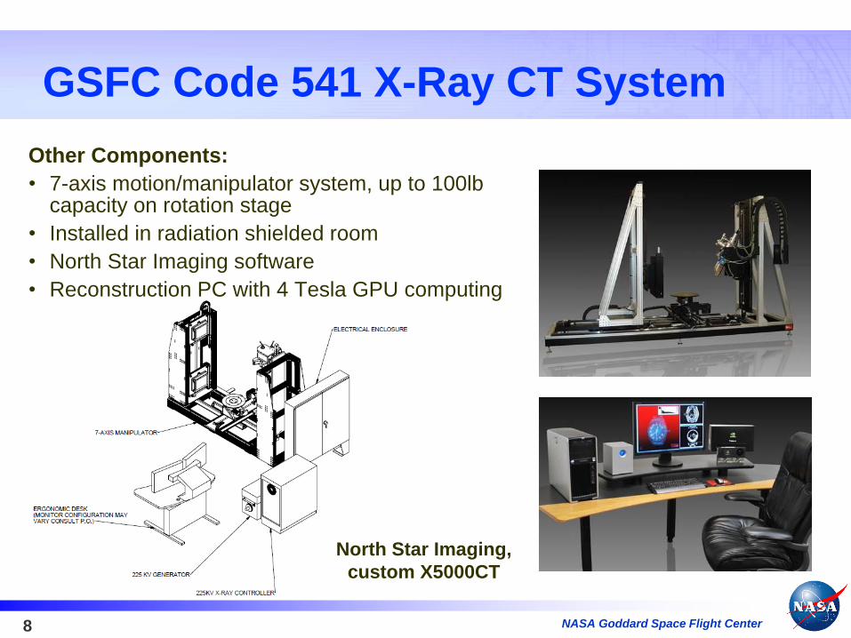
Other Components:
• 7-axis motion/manipulator system, up to 100lb capacity on rotation stage
• Installed in radiation shielded room
• North Star Imaging software
• Reconstruction PC with 4 Tesla GPU computing
North Star Imaging,
custom X5000CT

NASA Goddard Space Flight Center9
Examples - Composites
Impact Damage in
Structural Composite
Epoxy Voids in Composite
Boom End Fitting
NASA Goddard Space Flight Center10
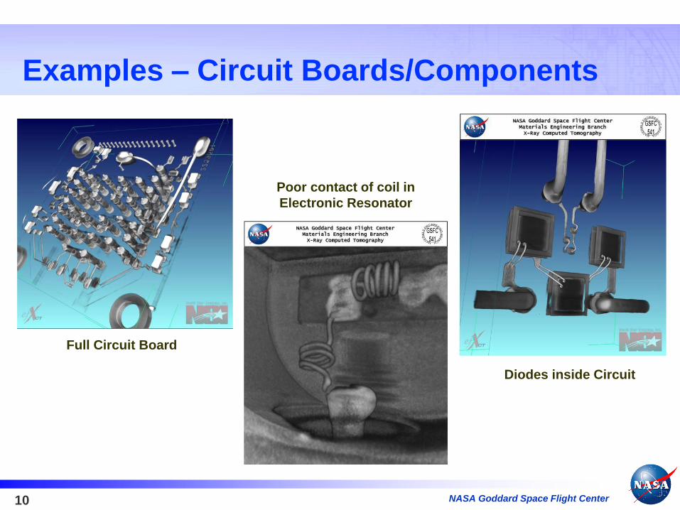
Examples – Circuit Boards/Components
Poor contact of coil in
Electronic Resonator
Full Circuit Board
Diodes inside Circuit
NASA Goddard Space Flight Center11
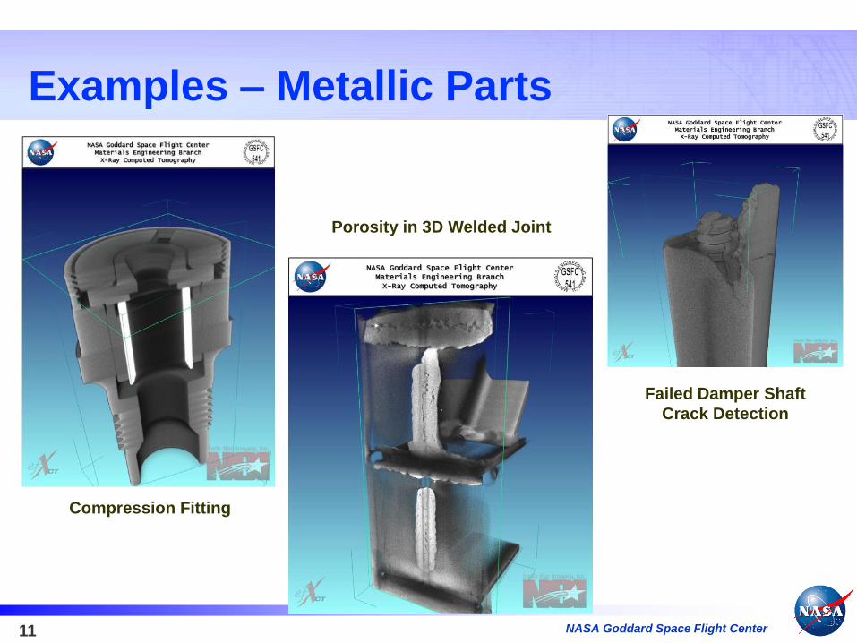
Examples – Metallic Parts
Porosity in 3D Welded Joint
Failed Damper Shaft
Crack Detection
Compression Fitting

NASA
Goddard Space Flight Center
Materials Engineering Branch
OSMA NDE Program Task 1:
Development of X-Ray
Computed Tomography (CT)
Inspection Standards

NASA Goddard Space Flight Center13
Task 1 Objectives
• Develop a set of tools to assess Computed Tomography (CT) system performance, similar to those used for traditional x-ray NDT to measure unsharpness, resolution, or contrast sensitivity. Currently there are no universally accepted or commercially available IQIs for CT
• Identify materials and design internal features useful for assessing inspection capabilities
• Fabricate Image Quality Indicators (IQIs) to simulate above features
• Analyze IQI volume data to assess CT detectability limits, contrast sensitivity, and resolution
• Reverse approach…
Use CT system to ascertain AM material build defects and limitations

NASA Goddard Space Flight Center14
Standard Image Quality Indicators
From left: Convergent line pair gauge, duplex line pair gauge, step block, plaque penetrameter [ndtsupply.com]
2D DR Image 3D CT Image

NASA Goddard Space Flight Center15
IQI Development Concept
CT system showing rotational axis. Since
reconstruction is based on multiple viewing angles,
we proposed using axial-symmetric standards to
measure system performance.
IQIs conducive to CT
(rough concepts shown above: not
actual designs).

NASA Goddard Space Flight Center16
MaterialPH1 Stainless Steel (15-5
analog)Titanium 6Al-4V
Vero White Plus RGD835
(proprietary photopolymer)
ManufacturerGPI Prototype and
Manufacturing Services
GPI Prototype and
Manufacturing ServicesAlio Designs
Build Method Direct Metal Laser Sintering Direct Metal Laser Sintering PolyJet
Layer Thickness
(µm)40 30 30
Minimum
Feature (mm)0.3 0.5 1.6
AM Fabrication of Phase 1 X-ray CT IQIs

NASA Goddard Space Flight Center17
Assess AM IQIs using x-Ray CT
Assess x-Ray CT using AM IQIs

NASA Goddard Space Flight Center18
Assess Phase 1 AM IQIs using x-Ray CT
Image by G. Fischetti

NASA Goddard Space Flight Center19
Assess Phase 1 AM IQIs using x-Ray CT
Images by G. Fischetti

NASA Goddard Space Flight Center20
Assess Phase 1 AM IQIs using x-Ray CT
Images by G. Fischetti

NASA Goddard Space Flight Center21
5.5 mm
Assess Phase 1 AM IQIs using x-Ray CT
Images by G. Fischetti
6 mm 6.5 mm 7 mm

NASA
Goddard Space Flight Center
Materials Engineering Branch
OSMA NDE Program Task 2:
X-ray CT Detectability of AM
Parts via Point Estimate/POD

NASA Goddard Space Flight Center23
Motivation
• Key findings from NASA’s "Nondestructive
Evaluation of Additive Manufacturing State of the
Discipline Report" (2014):
• For AM parts, inherent complexity drives the need for
advanced NDE by x-ray Computed Tomography (CT).
• CT is considered to have the greatest potential based on
its unique ability to provide quantitative 3-dimensional
data across a wide range of materials, dimensions, and
shapes.
– Fabrication of physical reference standards is
needed to verify and validate CT NDE data.
• Probability of Detection (POD) data does not exist for common AM flaw types.
• Crucial to establishing inspection limitations for CT.

NASA Goddard Space Flight Center24
Task Objectives
• Identify common AM flaw types (i.e., shapes, sizes, locations, materials, applications, etc.)
• Work with partners LaRC, JSC and MSFC to design flaw specimens
• Want to build off defect detection work being done at MSFC to pick defect types and flaw sizes relative to SLS applications.
• Identify vendors to fabricate seeded flaw specimens
• Round-robin inspections on produced flaw specimens
• Perform probability of detection (POD) analysis to assess CT system performance for select AM - produced flaws
• Utilize data from “round-robin” inspections

NASA Goddard Space Flight Center25
Flaw Specimen Development
CT system showing rotational axis and cone beam.
flaw
flaw
flaw
flaw
flaw
X-ra
y S
ou
rce
• Flaw standard(s) will incorporate a “stack” of flaws embedded into a compound, net-shape AM part to reduce fabrication costs
• If flaws spaced sufficiently apart, roughly parallel nature of x-ray beam permits independent inspection of each flaw

NASA Goddard Space Flight Center26
Design of Experiments:
Iterating Flaw Specimen Design Variables
Flaw type (voids, crack-
like flaws, lack of
fusion, excess material)
Exterior specimen
shape (cylinder,
prism, plate)
Specimen
material (Al,
Ti 6Al-4V, SS)
Flaw locationFlaw size Flaw
orientation

NASA
Goddard Space Flight Center
Materials Engineering Branch
A Few Related AM Activities within
the Materials Branch (Code 541)
and Across GSFC
NASA Goddard Space Flight Center28
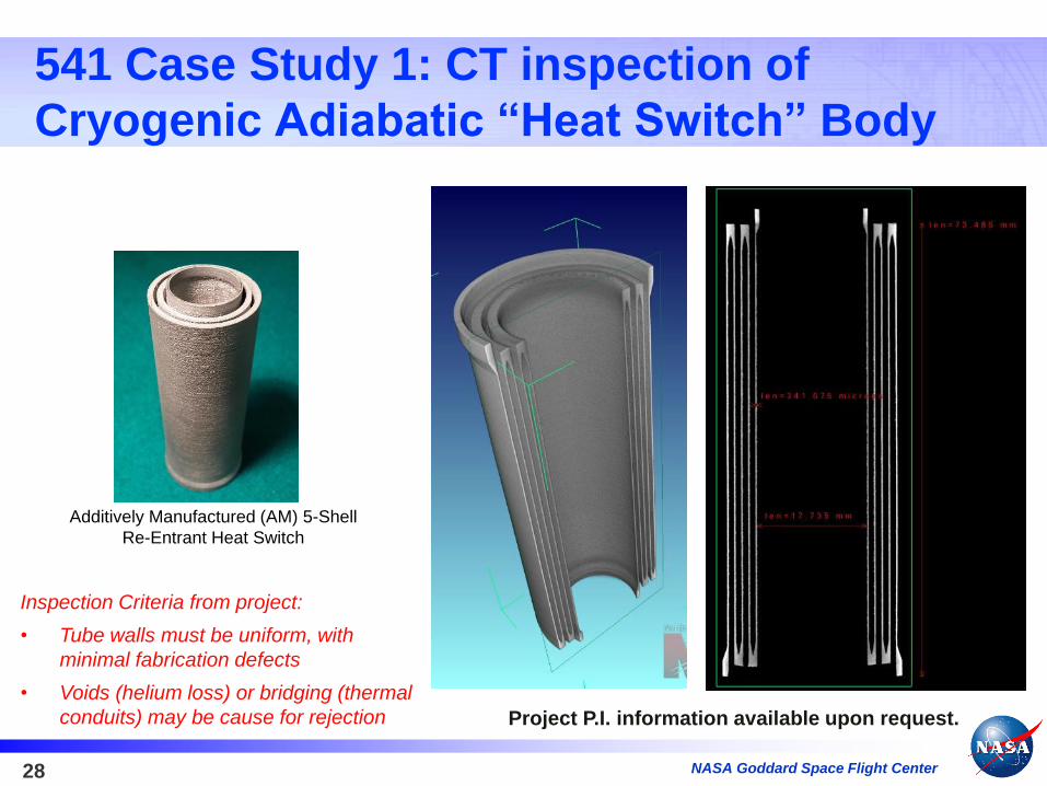
541 Case Study 1: CT inspection of
Cryogenic Adiabatic “Heat Switch” Body
Additively Manufactured (AM) 5-Shell
Re-Entrant Heat Switch
Inspection Criteria from project:
• Tube walls must be uniform, with
minimal fabrication defects
• Voids (helium loss) or bridging (thermal
conduits) may be cause for rejection Project P.I. information available upon request.

NASA Goddard Space Flight Center29
541 Case Study 1: CT inspection of
Cryogenic Adiabatic “Heat Switch” Body
Indexing
seam
bridging
Project P.I. information available upon request.

NASA Goddard Space Flight Center30
Case Study 1: CT inspection of Cryogenic
Adiabatic “Heat Switch” Body for Astro-H
seam
bridging
• These flaws were found relatively easy with CT and the Pass/Fail requirement was clear.
• But what if the Program’s Pass/Fail criterion is not so binary and flaws of a certain size need detected?
Project P.I. information available upon request.

NASA Goddard Space Flight Center31
Case Study 2: CT inspection of AM
Venturi Tube
Project P.I. information
available upon request.

NASA Goddard Space Flight Center32
Case Study 2: CT inspection of AM
Venturi Tube
Project P.I. information
available upon request.

NASA Goddard Space Flight Center33
Aerosol Jet 3D Printing of High
Resolution Conductive tracesAerosol Jet
Printed Traces on
Flexible Surface
(Optomec)
Process Overspray analysis (parametric study
to improve upon several process variables)
Known flaw types
Project P.I. information available upon request.

NASA Goddard Space Flight Center34
3D Printed Invar ® Coronagraph Bench
• Compact Optical Assembly (COA)
and optics standoffs for the Next
Generation Visible Nulling
Coronagraph (NG-VNC) ETU.
• Improves dimensional stability by
eliminating mechanically fastened
interfaces, thereby ensuring the
bench achieves its residual
stability requirement.
• Laser Powder Bed Fusion
Project P.I. information available upon request.

NASA Goddard Space Flight Center35
Prototype AM tools for the Satellite
Servicing Capabilities Office (SSCO)
Project P.I. information available upon request.

NASA Goddard Space Flight Center36
3D Printed PEKK for ATLAS Telescope
Fiber Optic Routing
3D printed, Carbon
doped PEKK developed
for high temperature
extreme, high static
dissipative electronics
applications.
FDM by Stratasys
Project P.I. information available upon request.

NASA Goddard Space Flight Center37
3D Printed Ultem 9085 for ATLAS
Telescope cable clamping
3D printed, low
outgassing Ultem 9085
developed to replace
metallic cable fasteners
near critical detectors
and sensitive hardware
FDM by Stratasys
Project P.I. information available upon request.

NASA Goddard Space Flight Center38
Further Traction for AM-related Activities*
• GSFC Additive Manufacturing Working Group (Viens/300)
• A GSFC working group for AM was initiated and has helped to bring individuals across the Center
involved in AM in contact so there is a vehicle of sharing ideas and a known set of personnel that
might be used as a resource in the further utilization of AM.
• Several field trips to local AM facilities were conducted.
• NASA Additive Manufacturing Community of Practice was established on the NASA Engineering
Network. The CoP has gained limited traction as yet but contributors are actively soliciting additional
participation from across the agency.
• Code 100 participating as NASA Rep in America Makes (Ted Swanson)
• MUSTANG is an in-house effort to standardize spacecraft avionics packaging. Has been used on two
separate missions (GEDI, PACE OCI) and uses AM to produce various parts using nylon, carbon fiber,
Kevlar, magnetic materials, etc. AM parts are compared to traditional machined parts. (Robert Gheen)
• IPO Office has submitted SBIR topics on AM (Ericsson, Smith)
• The Cross Cutting Technologies Office has Identified AM as Technical Thrust area moving forward
(Johnson, 500)
*GSFC AM Notes courtesy of M. Viens/300