ad-776 587 cast.acrylic plastic dome for undersea applications · large, acrylic plastic domes for...
TRANSCRIPT

, .-.- --- - , 7.. .•. . .. . . . . - . .. . .-. . . .. .
AD-776 587
CAST.ACRYLIC PLASTIC DOME FOR UNDERSEA APPLICATIONS
"NAVAL UNDERSEA CENTER
1- I
JANUARY 1974
DISTRIBUTED BY:
National Technical Infs.rnatn ServiceS-. S. DEPAT WENT OF COMMERCE
U EPAR
• * -•.
UNCLASSIFIEDSecurity Classification
DOCUMENT CONTROL DATA.- R & D(Security classification of title. body of abstract ande Indexing annlotat ion mnum( be entered when flee overall report Is closslfled)
I. ORIGINA TING ACTI VITr f`ColporAte 04u11101) Za. REPORT SECURITY CLASSIFICATION
Naval Undersea Cente. - UCASFE
;RSan Diego, California 92132 2.GROUP -0
3- REPORT TITLE
CAST ACRYLIC PLASTIC DOME FOR UNDERSEA APPLICATIONS
4- EC R'PT I VZ NO T E (TS-pe aof report dnd Incle,.loe dotes)Research and Development, July 1972 - tune 1973
5 AU T4O RMS 'Flt~t name, middle Jaillel. last name)
Jerry D. Stachiw
6. REPORT DATE 78. TOTAL NO. OF PAGES .NOOFRP---
January 1974 32 I$R f ONTRAC OR GRANT NO. 0 *. ORGIN1 4 TORNS REPORT NUMI.BERl(S)
b.PRCJEC T NO. Funded internally through the NUC TP 383IdpnetExploratory ___________________________
Deelpm. Prga9b. OTHER REPORT NOMS (Any other number, theatmay be &*sgIned
to 1. OISTPISUTION STMTEMENI
Approved for public release; distribution unlimited.
I]. SUPPLEMeNTARY NOTES' -12 - SPONSORINJG MILITArY ACT) VITe
Director of Nrv-, L1aboratoulesWashington. D. C. 20390
I3. AuS~ts T
An acrylic plastic hemispherical domne with a 78-inch outer diameter, 65.25-inch inner diameter and 7-inch-long skirt has been successfully cast, machined, and equipped with a metallic mounting flange. The mounting flangewill allow mating of the cast plastic dome to a surface ship hull, where it will serve as an impact-resistant underseaobservation chamber that will afford its occupants panoramic vision of subsurface hydrospace. Other potentialapplicatinns for such cast domes are in deep submergence vehicles, continental shelf ocean bottor,2 habitats, pressur-ized aquaria, and hyperbaric chambers. This dome is applicable to depths in the 0- to 2,500-foot range providng that
I' .the right method is used for attaching the dome to the vehicle or habitat. The mechanical properties of the massivedone casting have been found to be siniianty' less than the typical properties of flat plates cast solely from acrylicmonomer.
Raprodueed by-. NATIONAL TECHNICAL
ký INFORMATION SERVICESptinglield, VA. 22151
(PAGE,47 UNCLASSIFIED'p0102.014. 6600 U cusity CIIubalfication
UNCLASSIFIEDSecurity Clarsificrtion
14KEY WORDS LINK A LINK 8 LINK C
ROLE WT ROLF WT ROLE WT
Acrylic resins
Acrylic casting
Viewports
Submersible windows
Spherical shells
Windows
Submersibles
Habitats
Observation chambers
'41
FOR
DD ,...1473 (BACK) U LASSIFI-D
(PAGE 2) 8.cwity Classification
14//
NUC TP 383
CAST ACRYLIC PLASTIC DOMEFOR UNDERSEA APPLICATIONS
* byJerry D. Stachiw
Ocean Technology Department
January 1974J
n,0ZU?~7APR 9 1sti
Reproduced by
NATIONAL TECHNICALB* INFORM4TION SERVICE
U S Department of CommerceSpringfield VA 22151
Approved for public reiesse, distribution unilimited.

NAVAL UNDERSEA CENTER. SAN DIEGO, CA. 92132
AN ACTIVITY OF THE N AV AL M ATE R IA L CO MMAND0ROBERT H. GAUTIER, CAPT, USN Wmn. B. McLEAN,'Ph.D.
Commander Technical Director
ADMINISTRATIVE STATEMENT
This report summarizes work performed between July 1972 and June 1973* to investigate transparent structural materials for undersea application. The work
was supported by the Director of Naval Laboratories through the IndependentExploratory Development Program.
ACKNOWLEDGEMENT
The authý,;~ is indebted to Mr. A. E. Nichols, Jr. of Cadillac Plastic andChemical Company for his technical contribution to the successful casting uf theacrylic plastic eome.
4~CE~-lion
UNANo~i~j &I 11 ~Released by............. H. R. TALKINGTON, Head
...... ........................... ... Ocean Technology Department
..............
DS lurON/AVAuISLT CODES..
A.A..
U~
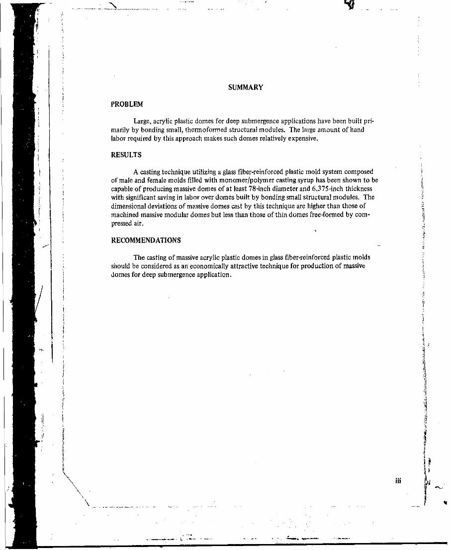
SUMMARY
PROBLEM
Large, acrylic plastic domes for deep submergence applications have been built pri-marily by bonding small, thermoformed structural modules. The large amount of handlabor required by this approach makes such domes relatively expensive.
RESULTS
A casting technique utilizing a glass fiber-reinforced plastic mold system composedof male and female molds filled with monomer/polymer casting syrup has been shown to becapable of producing massive domes of at least 78-inch diameter and 6.375-inch thicknesswith significant saving in labor over domes built by bonding small structural modules. Thedimensional deviations of massive domes cast by this technique are higher than those ofmachined massive modular domes but less than those of thin domes free-formed by com-pressed air.
RECOMMENDATIONS
The casting of massive acrylic plastic domes in glass fiber-reinforced plastic moldsshould be considered as an economically attractive technique for production of massivedomes for deep submergence application.
~i,. I
II
VV
t
B#4
CONTENTS
INTRODUCTION IDISCUSSION 2
Design of Dome 2Attachment for the Dome 2Casting Technique 3Machining of Dome 4Fabrication of Attachment 4Mating of Attachment to the Dome 4
OBSERVATIONS 5
FINDINGS 6
CONCLUSIONS 6
RECOMMENDATIONS 6
FIGURES AND TABLE 7
APPENDIX: DESIGN HINTS 23
REFERENCES 27
iv
-- ,. --
INTRODUCTION
Many ocean engineering systems require transparent structural components thatserve as windows. Since the size of the window directly influences the field of view that thewindow provides, a premium is placed on size. However, large sizes require that windows bequite thick.
"Thick, plane, acrylic plastic windows can be readily manufactured either by laminat-ing many thin sheets or by casting massive blocks. In either case the technology is well devel-oped and plane, acrylic plastic windows of almost any thickness and size can be obtainedfrom industrial suppliers on a fixed-price basis. Still, plane windows are not as much in de-mand as are spherical shell windows, whose shape makes them structurally superior (refer-ences 1-10).
Unfortunately, the technology for the fabrication of spherical shell windows is notso advanced as is that for plane windows. Thin windows can be readily fabricated by blow-ing with compressed air, with or without a mold, but the resulting hemispheres are of varyingthickness and must be limited in their operation to shallow depths. Thick windows havebeen fabricated only (1) by laminating many thin, blown shells; (2) by hogging-out massivecastings; or (3) by assembling and bonding many small structural segments. Of these threeapproaches, the laminating produces shells of varying thickness, while the hogging-out is pro-hibitively expensive. Only the bonding of small, identical segment assemblies has producedthick, spherical shell windows of uniform thickness at a tolerable price. It was this techniquewhich was used to fabricate spherical hulls for the NEMO, MAKAKAI, and JOHNSON SEALINK deep submergence vehicles. Bonding left a lot to be desired in terms of cost, becauseit entailed an inordinate amount of hand labor. Obvicusly, another technique was neededthat would require significantly less hand labor while producing thick, spherical windowswith acceptable dimensional tolerances.
A fabrication technique which seemed promising was the casting of monolithic hemi-spheres. It was thought that if problems of excessive shrinkage, cracking and generation ofbubbles during the polymerization process could be surmounted without excessive invest-
ment in tooling, this process would permit the production of inexpensive, spherical, acrylicplastic windows of large size.
Realizing the potential savings if an inexpensive casting technique could be developed,Sthe Naval Undersea Center initiated studies of two casting techniques. The first would mini-mize the cost of tooling in exchange for allowing (I) large dimensional tolerances in thesphericity, diameter and thickness of the casting and (2) a large amount of hand labor forpolishing ot' the cast surfaces. The second would (I) minimize the amount of hand labor forpolishing and (2) keep the thickness, sphericity and radius within tight dimensional toler-ances, but would require expensive tooling. This paper describes the first study.
4l
DISCUSSION
DESIGN OF DOME
The objective of the casting technique study was the fabrication of an acrylic plastichemisphere with a nominal 78-inch outer diameter, 65.25-inch inner diameter and 7-inchcylindrical skirt. This dome was dimensioned to serve as an undersea observation chamberfor the small waterplane area hull vehicle SSP KAIMALINO. Since the observation chamberwas to be mounted only approximately 12 feet underwater, the hydrostatic pressure wasnot of sufficient magnitude to control the structural design of the dome.
Instead, the thickness of the dome was chosen on tile basis of the dynamic impactto which the hull could be subjected when accidentally striking a water-logged floating log.The 6.375-inch thickness chosen for the dome represented a good compromise as it gave thedome a reasonable impact resistance (roughly equivalent to that of 0.375-inch mild steel)while at the same time keeping its weight and cost at an acceptable level.
An additional benefit of such a thick wall was that the dome could also serve as apanoramic window for submersibles and ocean bottom habitats operating to a depth of 1 ,000feet. In this manner, once the tooling was fabricated for casting of the dome, the output ofthe tooling would not be limited to impact-iesistant transparent bows for surface ships, butalso would provide relatively inexpensive observation cupolas for submersibles and underseahabitats.
ATTACHMENT FOR THE DOME
Besides operational parameters like hydrostatic pressure and dynamic impact, tilemethod of attaching the 3,000-pound acrylic casting to the metallic hull of the SSP KAIMA-LINO had to be considered. The pitching of the hull in rough water, depending on its am-plitude and frequency, could subject the acrylic casting to gravitational forces in excess. of10,000 pounds. Forces of such magnitude and the presence of seawater eliminated adhesivesfrom the consideration for attachments.
Several mechanical attaclunent systems were considered before settling on the chosendesign. Those that were conmdercd, but ultimately rejected, were attachments that requir,,deither straps or retaining bars pressing against the convex surface of the dome and thusrestricting tile panoramic view from inside the dome. The design finally chos-en relied onmechanical fastening like those rejected, but becaus. of its layout did not obstruct in allymanner the view from inside the dome.
TIe basic features of the attachount "hosen for fabrication (figures 1 and 2)* arethesa:
1. A metallic. UAl-ated flange resrains the Joine against vertical static and dynuamicforces and provides the foundation to which the metallic hull of tile vehile and the splitring of the dome attachmtent are fastoted. Vice dome fits into the flange tathet loosely
uMipsawJ wb&k 14wgiouedJoib,'
-l
.*** -*-. *.. - --.
(approximately 0.125-inch clearance bl wepn the surfaces of the dome and interior of theflange) to dllow room for (a) thermal expansion and contraction of the dome under typicalconditions and (b) contraction of the dome tinder hydrostatic loading encountered at 12 feet.
2. A metallic split-ring restrains the dome against static and dynamic horizontalforces. The split ring fits rather snugly against the inner surface of the flange but ratherloosely (approxini-ely 0. 125-inch clearance) against the acrylic surface. Because of thisarrangement, the split ring can be fastened quite securely with bolts to the flange while stillallowing for limited radial and axial displacement of the dome due to thermal expansion andhydrostatic loading.
3. An elastomeric filler (silicone rubber) between the acrylic dome and the metalliccomponents of the attachment serves both as a seal against water and as a compliant cushionpreventing high stress concentrations at point contacts.
4. A cylindrical skirt on the (Iome mates with the metallic components of theattachment. To fit properly with the mating metallic parts of the attachment all surfacesof the skirt have been machined to close tolerances. This was necessary as the casting processchosen would not produce surfaces on tiut s-.1t to the desired close tolerances.
CASTING TECHNIQUE
The casting technique chosen* required that (I) a mix of acrylic monomer resin andpolymer granules be placed inio (2) glass-fiber reinforced epoxy molds that were subse-quently subjected to (3) elevated temperature and pressure inside an autoclave. Since acrylicspherical castings of such magnitude had never been cast before and a very distinct possibilityexisted that tile first attempt would be an expensive failure, a scale model of 24 inches out-side diameter and 2 inches wall thickness was east first. Whetn this casting was successful itwas decided to proceed with tile full scale 78-,ach-diatneter casting.
The distinctive feature of the casting arraingement chown was tile use of a sprueloc•ated at the apex of the dome to concentrate all gas bubbles in a part of tile casting tilatwould be subsequently cut off without decreasing the sixe of the finistlhd donte. An Ater-native approach to rentovil of thle gas bubble$ from the cast ing would be to p!ace tLie moldsupright and to pour ithe casting mix betweent the male and fentile molds. In tlis arrangementthe bubbles would rise and concentrate in1 the base of thc cylindrical skirt. Afler polyiriza-tion sýVveal ineltel of -the skir" t.so. conkaiiin, tileh bubbles would be Il"Chille4 off, lekavubehiild a bubble-free Cavsing.
1whe baWi rmasn for not chwooing tIte alternative ka4ing ar' genie-nt was the 77-inchlength of the skirt treuired to attach the finithet domne to tile vehicle bull. Ie NbmNbles weteto he concentrited ill the ase of the skirt, all additional 3 to.$ i6chs of skirt length woul-htv• to lie added to t(ie rough castivng. Tie rvswting, 10- to 1 '4twchicylindrical skirt pr•obablywould !a1c tilte re! oail of the male told very difficult a, the ctit mi, shrinks tiiliei-"ruately 8 to 10 pairltt upon tivyla¢tiont md wold nitt tthe Ow tindric4l ,- 'io of the
ollo quite eCeulily.
3 •,
S. --

MACHINING OF DOME
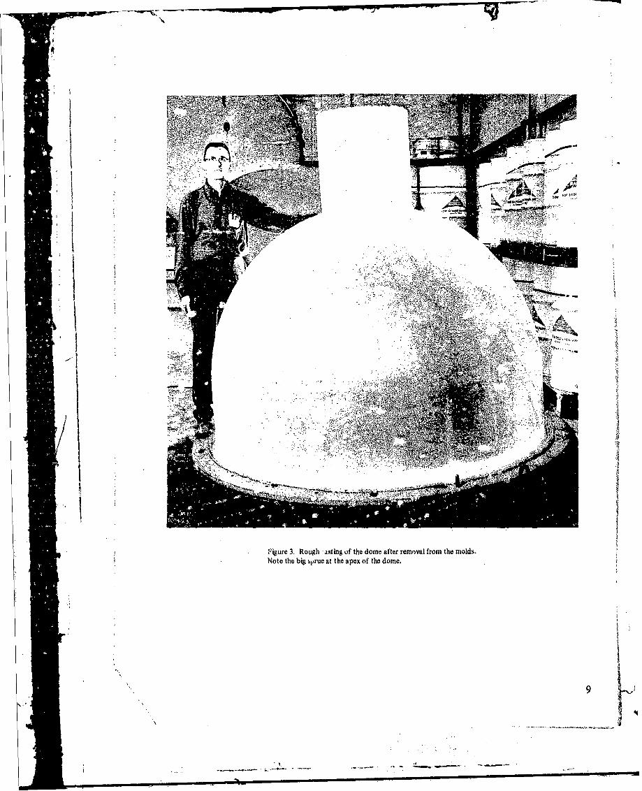
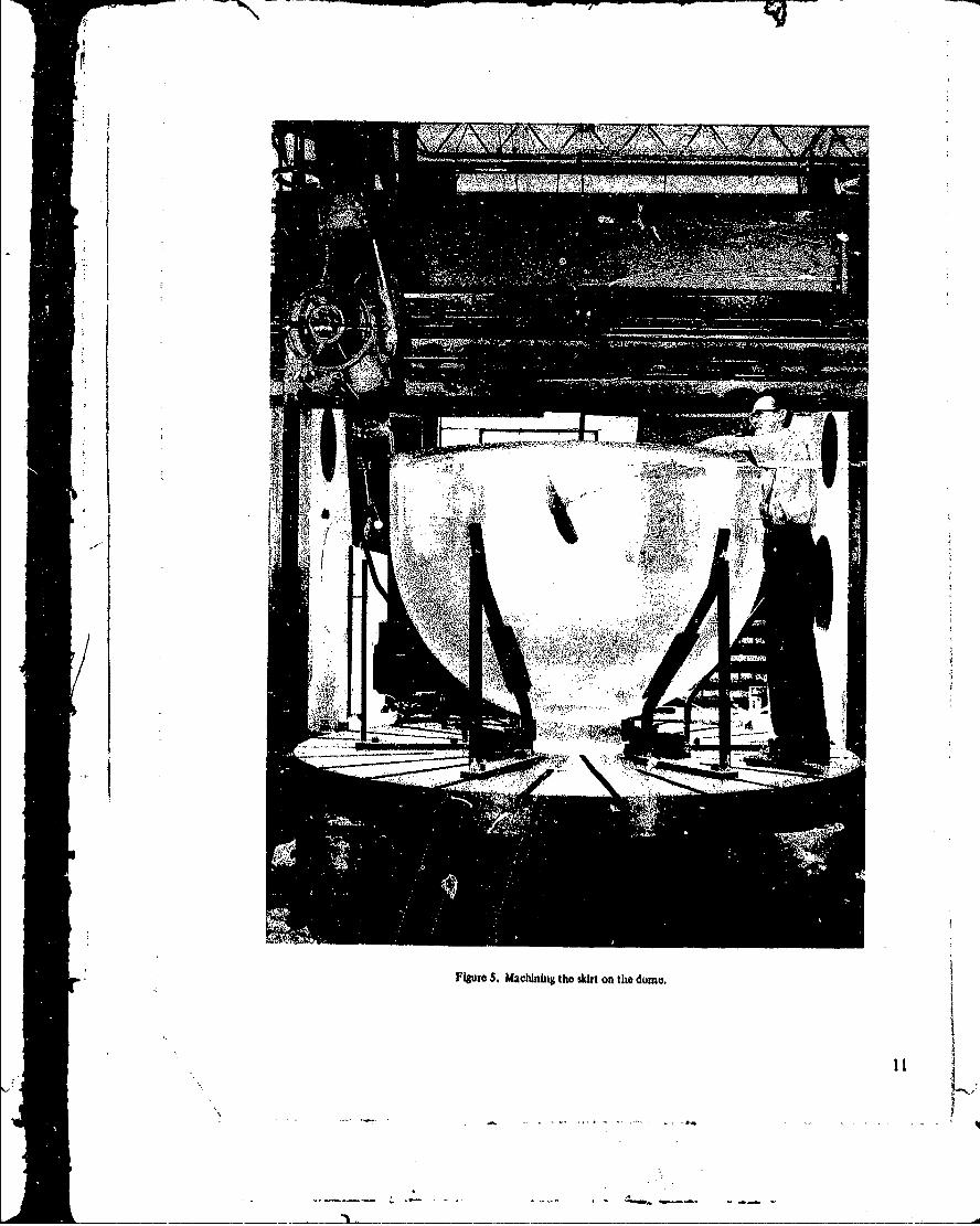
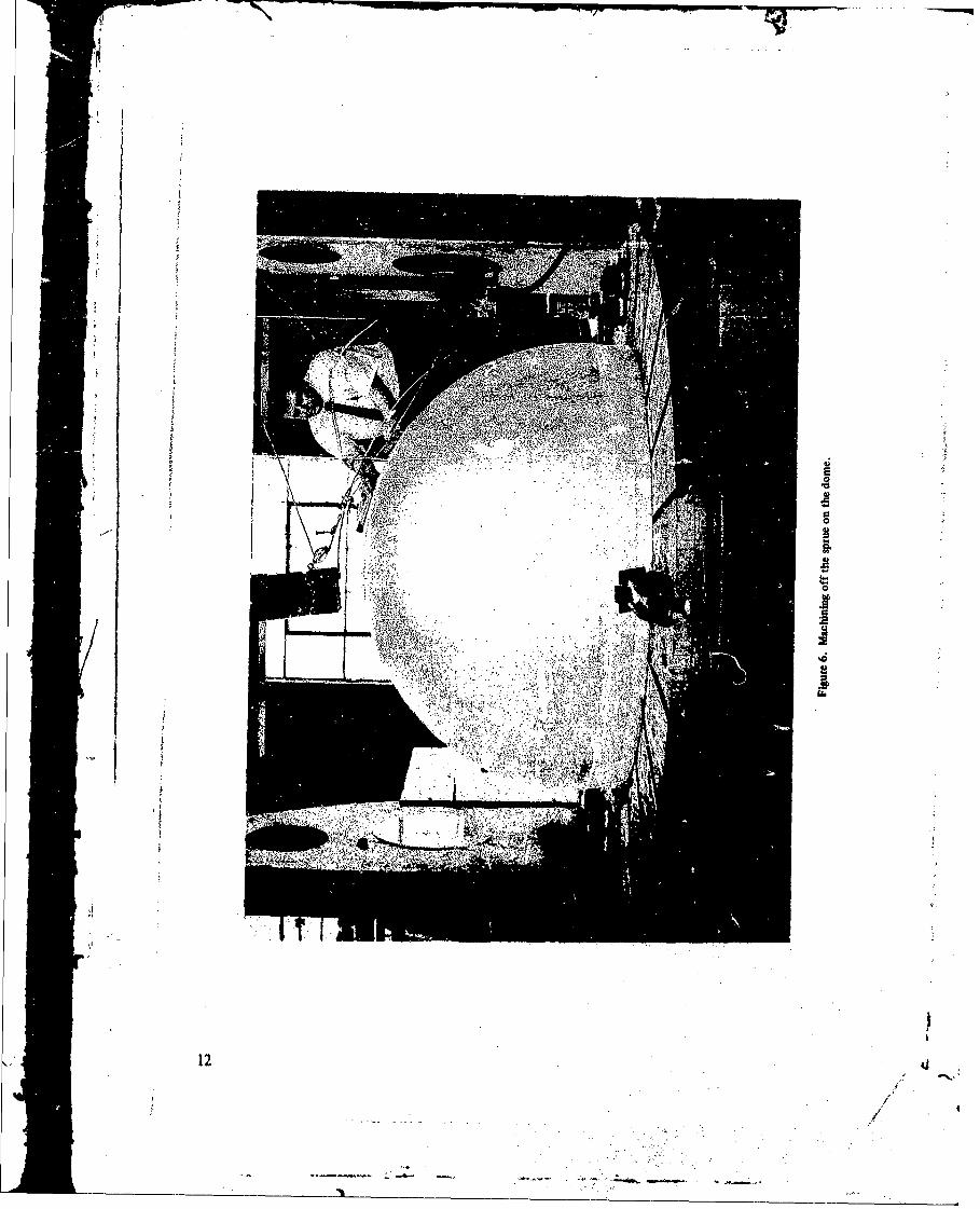
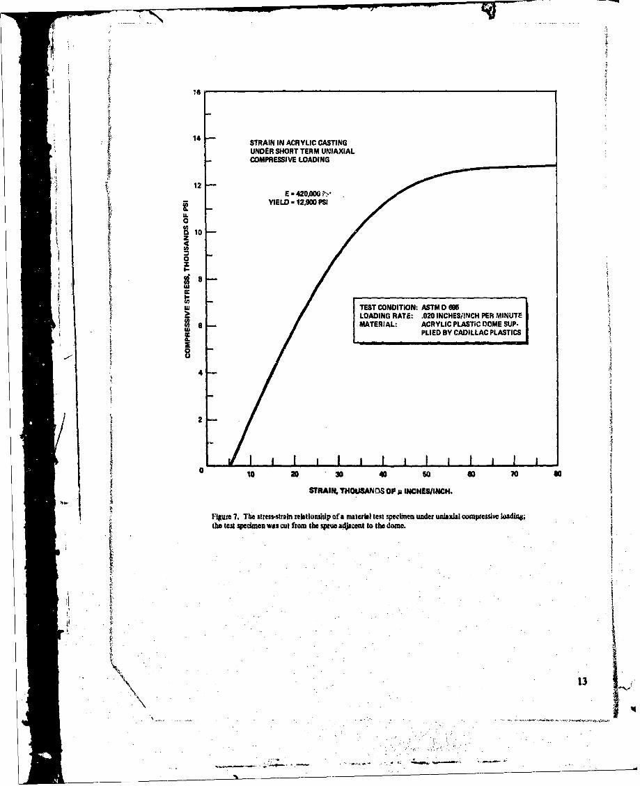
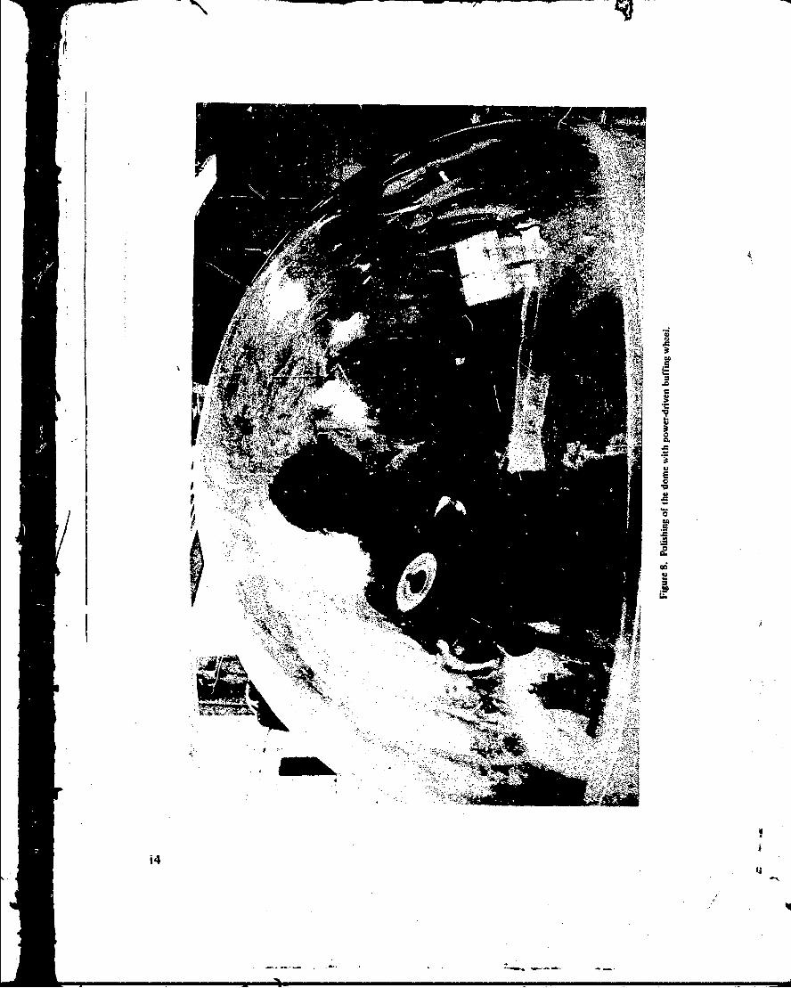
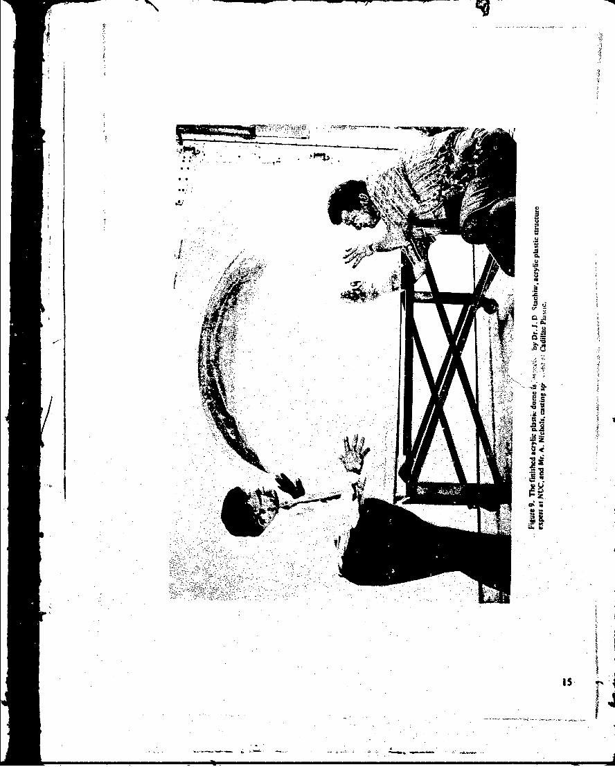
Tie succefully cast dome (figures 3 and 4) contained gas bubbles only in the upper5 inches of the sprue; the dome casting proper was virtually bubble-free. Tile first operationwas to machine the sprue flA.t so that it would serve subsequently as the base for tile domeduring machining of the skirt surfaces (figure 5) in a vertical mill. Next, the sprue was corn-pletely removed and the exterior surface was sanded (figure 6). Material test samples werealso cut from the sorie and used to test the mechanical properties of tile casting (figure 7,table I). Finally, !he intemiwr surface of the dome was sanded and all surfaces were poliblhed(figure 8). The completea dome was then carefully inspected (figure 9) and its dimnensionsrecorded.
FABRICATION OF ATTACiHMENT
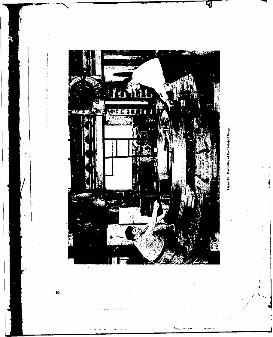
The U-shaped ILinge was fabricated by rolling and welding strips of mild steel. Tilerough U-channel structure was macl ined to final shape on the same vertical mill (figure 10)that was used for machining of the cast dome. Bolt holes for fastening of the flange to thehull and for attachment of the split ring to the flange were drilled with a portable drial heldin a magnetic clamp fixture.
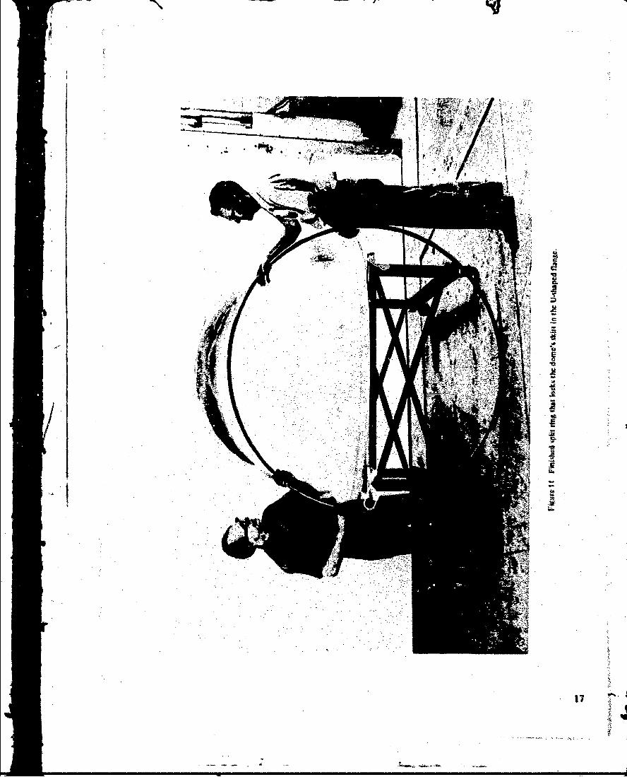
The split ring was fabricated by rolling, weiding and rough grinding of mild S.eelstrip. The ring (figure I1 was cut with a hacksaw in one place just prior to ioating of tileattachment components to tile dome.
MATING OF ATTACILMENT TO THE DOME
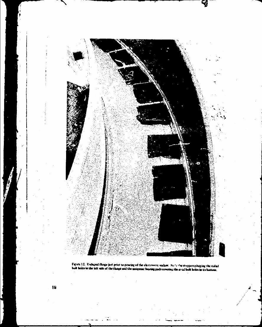
The first step in mating of tihe attachment to tile dome consisted of plugging the*k
holes in the Ushaped flange so thiat the- liquid etastomn-r would 1ot leak out prior to itspolyme.rization (figure 12t. The holt'l in the bask were covercd with 0.2-i4n1d-thick new:prene patches that not only covered the bolt holes but alwo wrvd a glacers between thedomle zwd the bol tom of the U.shapet! fh-f nge, Without the prlesce- of the neoprite space-rthe heavy dome would displ.cv tile hquid ctlto"Ver compktply mid the hasw of the *ifrtW-ouki bottom ninst the steel srufftce.
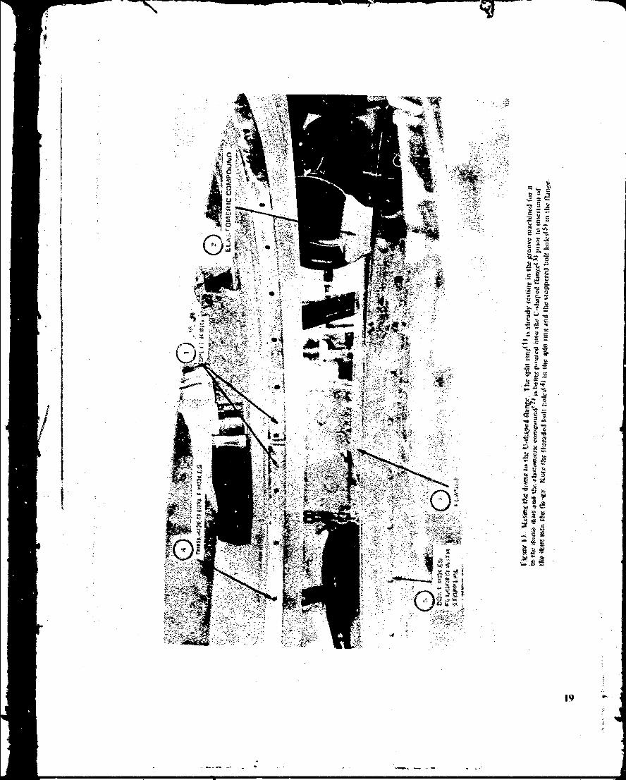
-The s-cout; Sp in the Inating pro "-- Ut Was to Qoanpfims amul insert the Spii riint h - the casting skirt ifng11 10"), NAI tht rtom w13)- Nady fot twa-
.- ~W With tihe US - -a fu % -•,1"1to thad Stcp wu; fi. lip of the* UM•|ii-W Mtqnc with the liýtovtt .•*-nipo~uftd
tfoCornbomw Two,4'1at Room Tcntjvtnum- Polyfuctit 3110RTV compaui) Au imawdi•-ety ke 'u ng the dom• into the flangv until the kwr bottomod on Whcoe M
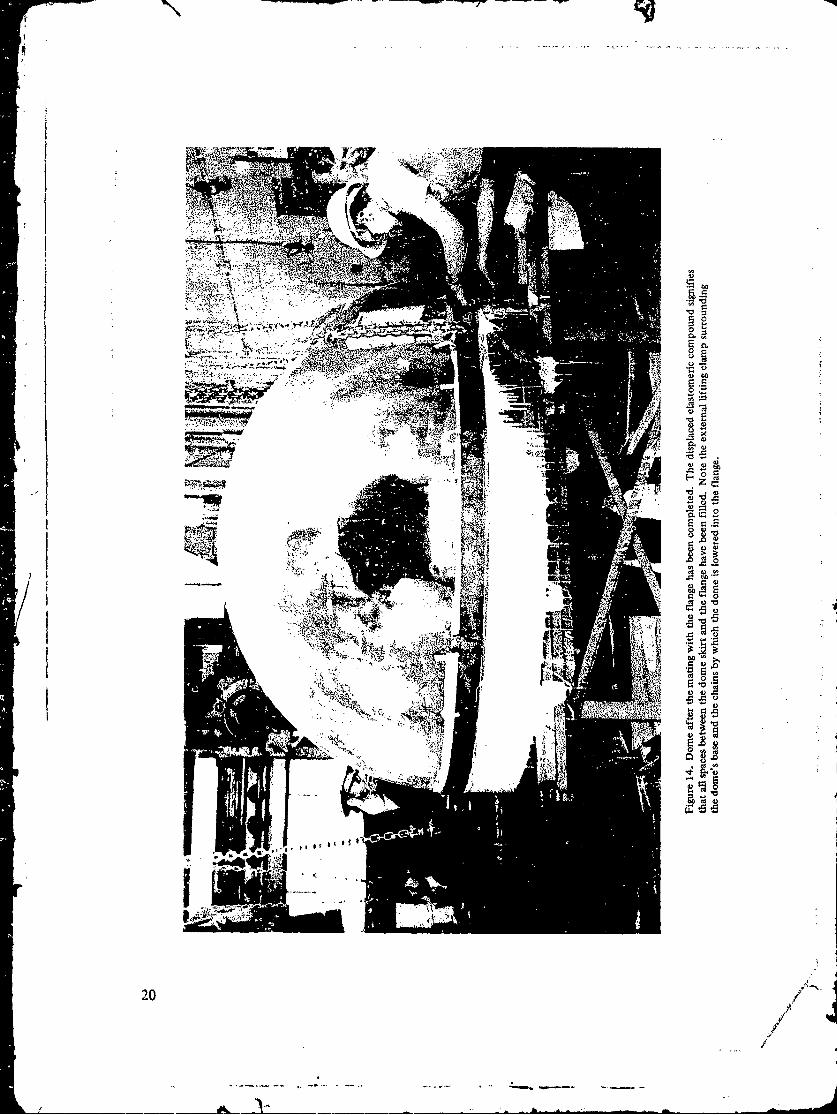
WW hd 'suvpluý 0twomoer woas ýýqwj- out (iutigmr 14).The fourth and fioul m.ep of the mitiv, 4•e•ut e gfir the dtwc ,,lidilie was
to dr4w tip i he Vplit firng apgtts the -Io ite4 flaw-g W1th I 1e0p of .-tai-ly 060i1t.0 boltt,kcmyn-al of thle ekt-md' ewltowr AW Oveialoe litic e'* damp ,slet4j t1W awtiqof the 414 ehlasert to the 44Wte.
4
~~~-- 0 I -lN il -_.
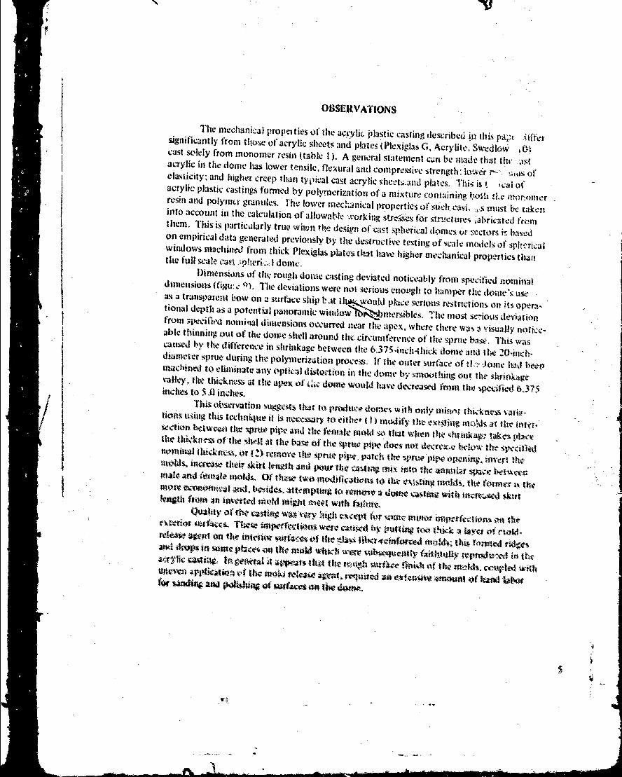
OBSERvATINS
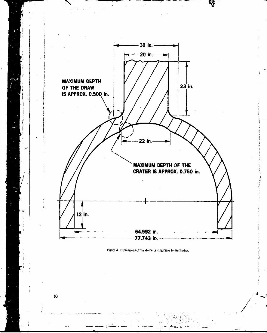
sgiiathe frmechanisa pofarlics If thle aCTRyli plastic castingi, dmesribeU inti aidesigniicanly fom thse o acr lcseets and plates (Plexiglas G, Acrylite, Swe-kdlowcast -olely from monomer resin (table I ). A general statement can bie niadv that 11w, .astacrylic in the (ionie has lower tensile, flexural and com~pressive strenigthl; lowur r-> jas otelasticity: and higher creep thian typical cast acrylic sheets-and plates. This is t ical ofacrylic plastic votedn byplmrztinO ixiure containting lysic trt1resin and polymery granullei. lihe lower mnechanfical properties of tscltca.ýi. ".s must Lbe takeninto account in the calculation of allowable -.orkinkg strcseýs for stracttres abricated frmmthem. This is particularly true. wheun the design of cuss sphe-tical domes- or sectors is basedVIOnl empirical data generated previously by the destructive te-sting of sc:ale models of sphe-ricalwindows inachiined from thick Plexiglas Plate&! tint have higher imechanical properties thantilt full scale cast Ipe~ domne.Diinxensons of flhe rough dome casting deviated noticeably from specified nominaldilmensions (Cigu:c: q). 'The deviations were not serious enoLugh to hamper thle dome), utseý
tional depth as a potential panoramic windo$ ý' Ifmersibles. The mlost sev-iotas deviationfrom 3pecil'h'd nomniwl dimensions occurred near rthe aplex, where there wais ý visual-ly nottctxable thinning out of the dome shell around the circumoference of thle spitec base. 'This wascatused by the differenice in shrinkage between thle b.3 l5-i-nch' hck domle and the 20-inch-diameter sprue during thle polymerization procce.s. It' thet outer surface of #L-: ttomnle hud beer
%-lly tieticns at he 'zx~fkldoul would imtt derawdfonte4 iit .7
trhQ mnlot 1Wvil w inch w-cc OWtwiv rt'pvoni c zinvt tluw-IRW.ittirv-ther 4Wt I thi' Pour mix itritg 4trhc manid'Ts.-ý crnpkxl t
wfr~se zf4ur An~ss' mtvti 4i 04n bbot iotwthNlmlity k - ý 0 Ww ilio l the -p dPgtnc.mito t
e ,-I vi o W a v C .- t k -a b y u t~ w u v 1 ." - 1 1 :Y ej O f old
I d ~ w W ~ f o n f fi i n t e 'i i m k tf t ýý m o f i l e ý ft t u -A W '; t m ' r o t d r d pia W- v o r S 1 1 S o e p o it ý o t h o W 4 4 w h 'A W Cm i m t "- t a ll y 6 M A 110 t$
4101kQaw. n o"Al;JW4t"Ott~ oh .mfc -- "o
-I V thcMqwfe'lw sowi vqmiýd g ex
FINDINGS
1. Molds made of plastic reinforced with glass fibers present an economical approachto tooling for the production of large, spherical shell acrylic castings providing that the per-missible tolerafces on thickness, diameter and sphericity are at least ±0.250 inches. Toac&eve tighter dimensional tolerances than ±0.250 inches the dome casting must be madeslightly oversize and subsequently machined down to the desired size.
2. The quality and mechanical properties of the acrylic plastic dome cast in glass-reinforced plastic molds ly Cadillac Plastic is acceptable for hydrospace applications prcvid-ing that the lower mechanical properties of the casting as compared to properties of com-mercially available cast acrylic plate are taken into account.
3. The design developed for the attachment of a hemispherical acrylic plastic dometo the metallic hull of a ship has been found to be economical to fabricate and easy toassemble with the dome.
CONCLUSIONS
It is feasible to cast very large acrylic plastic domes that do not require any subse-quent machining on the viewing surfaces at a reasonable investment in tooling and handlabor for polishing providing that one can accept deviations from nominal dimensions whichexceed those customarily associated with machined domes but are significantly less thanthose associated with vacuum- or pressure-formed domes from flat acrylic sheets.
RECOMMENDATIONS
It is recommended that the casting technique described in this report be utilized forthose hydrospace applications where (1) only one or two very large, thick acrylic plastictdomes of the same size are required and (2) the hydrostatic loading of the dome will be ofsuch magnitude that the dimensional tolerances of ±0.250 inch on the thickness, diameterand sphericity can be readily accepted. If the casting technique is used for the applicationsenumerated above it will provide the hydrospace engineer with very large domes at a rockbottom i, Ace.
6
/]
S"•IL""-.2v
•:=77.0 D0
•:, 76.970
z-- 66..'2s.o DIA ..
66.220
462_0 DIA 39.1_5 R 32.L0 R DETAI, A45.750 38.875 32.500
SEEN
0,5 118 R/ H
-1/2 R 6.000
4.280 5.970
4.2201.7801/R
1.0
\EQUATOR OF
HEMISPHERE
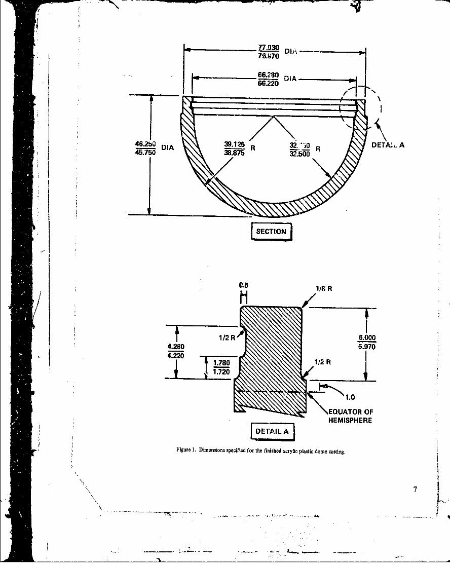
* ;Figure I. Dimensions specified for the finished acrylic plastic dome casting.
* 7II
"".....---~
FLANGE ASSEMBLY SECTION 100- CAST IN PLACER
SILICONE RBE
78.,25 OIA 75.0 "IA77.875 5/8-11NC-72ROD DETAIL A
.ZUZ~OIA V1/2-13NC-1 INCH LONG77*31/5 DIA E ,[3 QUIRED o u
-5.875
66.250 DIA65.000
. ao"*1
1/2 R 121N
2 67.000 DIANOTE: AFTER MACHINING CUT 66060 DIA I
THE RING IN ONE PLACE 66.000
MATERIAL: SOFT CARBON STEEL
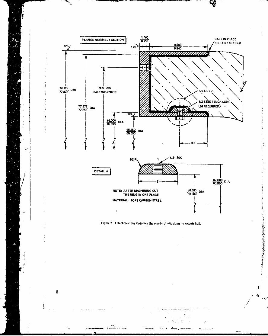
Figure 2. Attachment for fastening the acrylic plastic dome to vehicle hull.
4
)8
/
Il
Noteý% thtitre tteae o h oe
5, .
I P, 9
Figure~~ 3. Rog s goftedm-ftrrmvlfrmtemls
30 in.
[.,--- - 20 in.-----
MAXIMUM DEPTHOF THE DRAW 23 in.
IS APPROX. 0.500 in.
2 -in,
MAXIMUM DEPTH OF THECRATER IS APPROX. 0.750 in.
12 In.
64.992 In.77.743 In.
Figure 4. Dimensions of the dome casting prior to machining.
I0
;'10 / -
/"
- -z
I'
Figuje S. M~ac~nhig the Skis on the dome.
II x - -*--
t~ g
sy"fI~ -- 4Ai.)
I..
12 '
14STRAIN IN ACRYLIC CASTINGUNDER SHORT TERM UNIAXIALCOMPRESSIVE LOADING
4 12E - 420.000 ,',.
YIELD - 12,900 PSI
I.0
z
2
0
SW TEST CONDITION: ASTM D 696-- OAIN RA"•: 020INHE/INH ERMINTEJ •MATERIAL: ACRYLIC PLASTTIC DOME SUP-
4 •wPLIED BY CADILLAC PLASTICS
/ - , 4,
Z,Figutre 7. The stressstlmin rebtionzip ofa materl test specmea under unlaxial comaip vc oaduin;the test sWedmen was cut from the spue a0aent to the dmono.
V. 1
- .--. ".
06
R--
I es
-� w-�y- -r 91 - -�
$ I
'I
I .4
UtI,
7 U
I U
Pt
Ii --CUcr -& 77
.9.ifi. -b
S.
it '
t.I
is
16
N 91
k
U
C
iC
73
In
I
I'7
b
a...� �
tt
R&tIoUA Wbi tk it bit
At
hk - L'St
--. ----- ..
*19
0.-
.~ ~ ~ ~ ~ ... ....
0 4)
AM4
200
in/
20I
* 5S
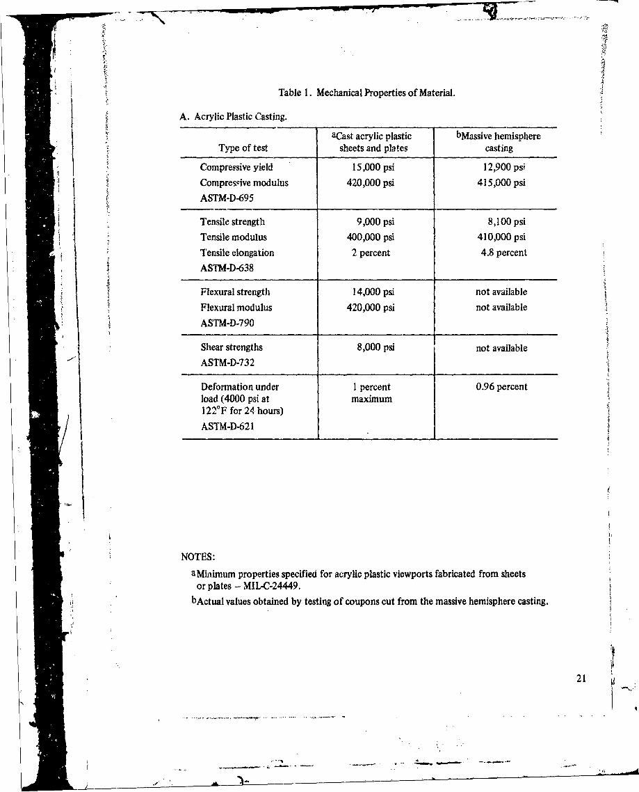
Table 1. Mechanical Properties of Material.
A. Acrylic Plastic Casting.
aCast acrylic plastic bMassive hemisphereType of test sheets and plates casting
Compressive yield 15,000 psi 12,900 psi
Compressive modulus 420,000 psi 415,000 psi
ASTM-D-695
Tensile strength 9,000 psi 8,100 psiTensile modulus 400,000 psi 410,000 psi
Tensile elongation 2 percent 4.8 percent
ASTM-D-638
Flexural strength 14,000 psi not available
Flexural modulus 420,000 psi not available
ASTM-D-790
Shear strengths 8,000 psi not available
"ASTM-D-732
Deformation under 1 percent 0.96 percentload (4000 psi at maximum122°F for 24 hours)
ASTM-D-621
NOTES:
aMhiimum properties specified for acrylic plastic viewports fabricated from sheetsor plates - MIL-C-24449.
bActual values obtained by testing of coupons cut from the massive hemisphere casting.
21- -
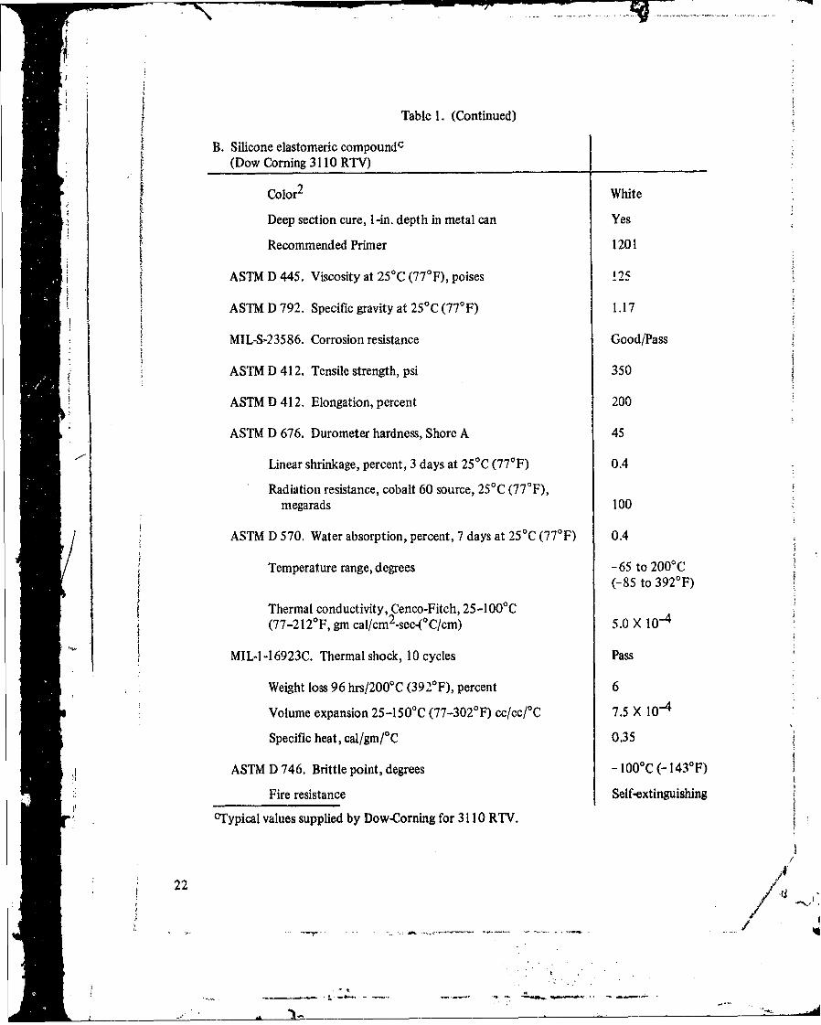
Table 1. (Continued)
B. Silicone elastomeric compoundc(Dow Corning 3110 RTV)
Color 2 White
Deep section cure, 1-in. depth in metal can Yes
"Recommended Primer 1201
ASTM D 445. Viscosity at 25°C (77 0 F), poises 125
ASTM D 792. Specific gravity at 25'C (77*F) 1.17
MIL-S-23586. Corrosion resistance Good/Pass
ASTM D 412. Tensile strength, psi 350
ASTM D 412. Elongation, percent 200
ASTM D 676. Durometer hardness, Shore A 45
"Linear shrinkage, percent, 3 days at 25*C (77°F) 0.4
Radiation resistance, cobalt 60 source, 25'C (77°F),megarads 100
ASTM D 570. Water absorption, percent, 7 days at 25 0C (77°F) 0.4
Temperature range, degrees - 65 to 2000 C(-85 to 392-F)
Thermal conductivity, Cenco-Fitch, 25-100°C(77-212 0 F, gm cal/cm 2 -sec-(0C/cm) 5.0 X 10-
MIL-l-16923C. Thermal shock, 10 cycles Pass
* Weight loss 96 hrs/200°C (392°F), percent 6
Volume expansion 25-150°C (77-3020 F) cc/cc/°C 7.5 X 10-
Specific heat, cal/gm/0 C 0.35
ASTM D 746. Brittle point, degrees - 100I C (- 1430 F)
Fire resistance Self-extinguishing0CTypical values supplied by Dow-Corning for 3110 RTV.
22- / . U
-. ..
* APPENDIX: DESIGN HINTS
For those engineers interested in utilizing the casting technique for acrylic plasticdomes or the design developed for the attachment of these domes to vehicle hulls, somebrief discussion of their limitations is in order.
CAST MATERIAL
Because the mechanical properties of cast massive acrylic plastic domes differ sig-nificantly from those of domes formed and subsequently machined from thick, commer-cially available plastic plates (for example, Plexiglas G, Acrylite or Swedlow 310), lowerstress levels must be utilized in their operation. Appropriate stress levels can be determinedusing the ratio of the mechanical properties of the dome casting to those of flat plates. Forexample, the ratio of the compressive strength of the dome casting to that of flat plate isapproximately 6/7 or 0.85. Therefore, the maximum working stresses in cast domes shouldrelate to the working stresses in domes fabricated from plates by roughly the same factor.
Since the maximum compressive working stress allowed at the present time forspherical Plexiglas manned capsules with a minimum proven 1,000 cycles and 106 hoursstatic fatigue life is only 4,000 psi,* the maximum allowable compressive working stress ina cast dome having the mechanical properties shown in table I should not exceed 3,400 psi(arrived at by multiplying 4,000 psi by 0.85). The maximum allowable tensile workingstress in a cast dome should, by the same token, not exceed 1,800 psi (arrived at by multi-plying the accepted 2,000-psi value for thick plates by a factor of 0.9, the ratio of the ten-sile strength of a cast dome to that of typical flat plate).
In those cases where the casting does not form a dome but has the shape of a spher-ical sector and the design is based on empirical short-term implosion data of scale modelsectors machined from Plexiglas G plates, a different approach must be used. Since the oper-ational depth of spherical sector windows is generally only a known fraction of their short-term implosion pressure, the only modification to their design procedure is to multiply themaximum operational pressure allowed for spherical sector Plexiglas G windows by the samefactor that was used in the previous paragraph to reduce allowable maximum compressiveworking stresses .in domes.
ATTACHMENT
21 The attdchment (figure 2) for affixing the dome to the vehicle hull has been specifi-cally designed for shallow depths of 100 feet or less. A similar attachment could be used fordepths to 1,000 feet, but the clearance between the U-shaped flange and the skirt wouldhave to be increased to allow for greater radial contraction under the larger hydrostaticpressure.
#Based on rihe results of the NEMO hull testhg program at the Naoal Civil Engineering Laboratory, reported Inreferences 11 through 15.
23
4 - -.
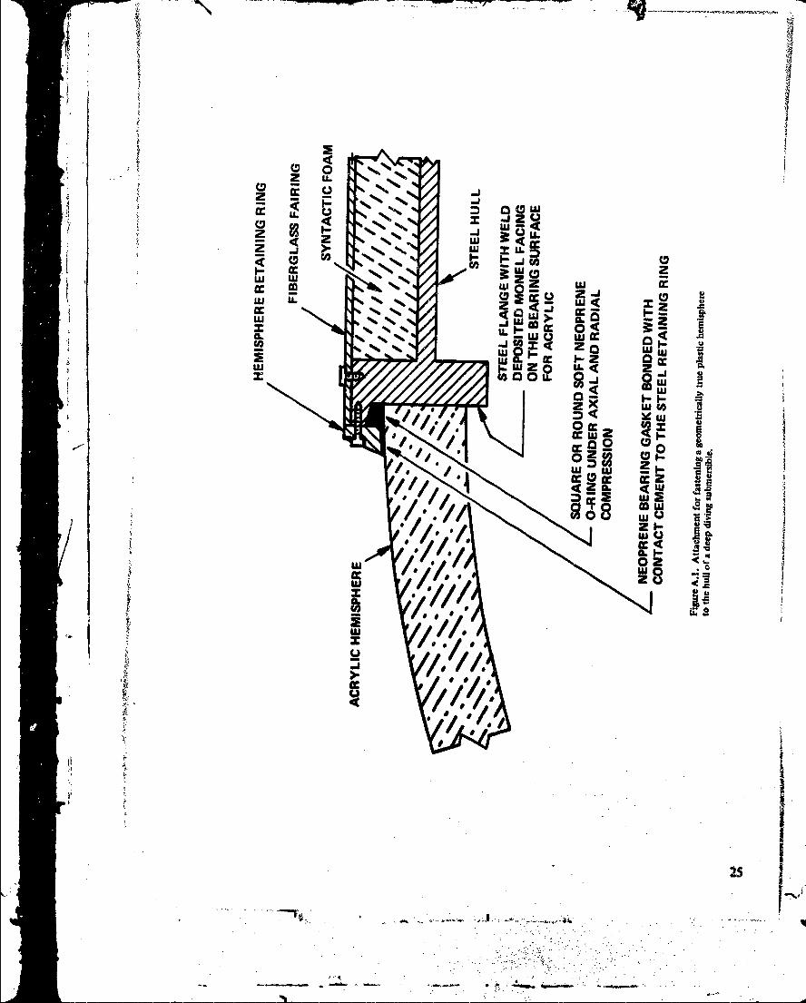
For depths beyond 1,000 feet the cylindrical skirt and the attachment developed forit (figure 2) would have to be eliminated altogether, as the bending stresses at the intersec-tion of the hemisphere and the cylindrical skirt become quite high. By 6limiriating the cylin-drical skirt on the casting its operational depth can be readily increased from 1,000 feet Loabout 2,500 feet. For mating the hemisphere to the hull of an underseas vehicle a different"attachment would have to be devised.
A typical attachment for a hemispherical dome is shown in figure A. 1. Its character-istics are (1) lack of restraint to the radial contraction of the sphere under hydrostatic pres-sure; (2) lack of an O-ring groove under the acrylic bearing surface; (3) presence of a smooth,metallic bearing surface on which the acrylic bearing surface can slide; and (4) an externallylocated rubber sealing gasket.
I I
-424
- 'FI ,
, 1
I/S~/ -
- -' - . '.: . "
7:777
z E U -- w
zU
w z~ -UF
wLU x 2 JS
-cc cc Z
w u >.IE L
Ulm o<
LLt
w- I- C
-- .. Z-. LL q z-.*~~*..
REFERENCES
Naval Civil Engineering laboratory. Technical Report R-5 12, Whindows for E~xternalor Internal Hydrostatic Pressure Vessels, pt. 1. Conical Acrylic Windows UnderShort Term Pressure Application, by J. D. Stach~iw and K. 0. Gray. Port Hueneme,California, January 1967 (AD 646882).
2. _______Technical Report R-527, Windows for External or Internal Hydro-static Pressure Vessels, pt. 2. Flat Acrylic Windows Under Short Term PressureApplication, by J. D. Stachiw, G. M. Dunn and K. 0. Gray. Port Huenemne, Califor-nia, May 1967 (AD 652343).
3. ______Technical Report R-645, Windows for External or Internal Hydro-static Pressure Vessels, pt. 4. Conical Acrylic Windows Under Long Term PressureApplication of 20,000 psi, by 3. D. Stachiw. Port Hueneme, California, October1969 (AD 697272).
4. _______Technical Report R-708, Windows for External or In,.eraal Hydro-static Pressure Vessels, pt. 5. Conical Acrylic Windows Under Long Term PressureApplication of 10,000 psi, by J. D. Stachiw and W. A. Moody. Port Hueneme,California, January 1970 (AD 718812).
5. ______Technical Report R-747, Windows for External or Internal Hydro-static Pressure Vessels, pt. 6. Conical Acrylic Windows Under Long Term PressureApplication of 5,000 psi, by J. D. Stachiw and K. 0. Gray. Port Hueneme, Califor-nia,iJune 1971 (AD 736594).
6. _____ Technical Report R-773, Windows for External or Internal Hydro-static Pressure Vessels, pt. 7. Effect of Temperature and Flange Configuration onCritical Pressure of 90 Degree Conical Acrylic Windows Under Short Term Loading,by J. D. Stachiw and J. R. McKay. Port Huenemie, California, August 1972(AD 748583).
7. ______Technical Report N-I 127, Flat Disc Acrylic Plastic Windows for iMan-Rated Hyperbaric Chambers of the U. S. N. Experimental Diving Unit, byJ. D. Stachiw, Port Hueneme, California, November 1970 (AD 71675 1).
8. ______Technical Report- R-63 1, Windows for External or Internal Hydro-static Pressure Vessels, pt. 3. Critical Pressure of Acryli Speia hl indowUnder Short Term Pressure Application, y3 .SakwadF W, Drier, PontHueneme, California, June 1969 (AD 689789).
9. Naval Undersea Center. NUC TP 315S, Acrylic Plastic Hemispherical Shells for NUC.Undersea Elevator, by J. D. Stadaiw. San Diego, Californiia, Septembe 1972(AD 749029).
ftecat psiem
10. NUC TP 355, Flanged Acrylic Plastic Hemispherical Shells forUndersea Systems by J. D. Stachiw. San Diego. California, August 1973 (AD 769213).
11. Naval Civil Engieering laboratory, Technical Report R-676, Development of aSpherical Acrylic Plastic Pressure Hull for Hydrospace Application, by J. D. Stachiw.
Port Hueneme, California, April 1970 (AD 707363).
12. Technical Note N-I 113, The Spherical Acrylic Pressure Hull ForHydrospace Application, pt. 2. Experimental Stress Evaluation of Prototype NEMOCapsule, by J. D. Stachiw and K. L. Mack. Port Hueneme, California, October 1970(AD 715772).
13. Technical Note N-1 094, The Spherical Acrylic Pressure Hull forHydrospace Application, pt. 3. Comparison of Experimental and Analytical StressEvaluations for Prototype NEMO Capsule by H. Ottsen. Port Hueneme, California,March 1970 (AD 709914).
14. Technical Note N-I 134, The Spherical Acrylic Pressure Hull for
Hydrospace Application, pt. 4. Cyclic Fatigue of NEMO Capsule #3, by J. D.Stachiw. Port Hueneme, California, October 1970 (AD 715345).
15. Naval Undersea Center. NUC TP 305, Effect of Bubble Indusions of the MechanicalProperties of Cast Polymethyl Metacrylat., by J. D. Stachiw. San Diego, California,August 1972 .(AD 746862).
"IA
i
I
iI •
•.I
A